brown low power sdr networked architecture for digital ... · proceedings of the sdr ’09...
TRANSCRIPT

Proceedings of the SDR ’09 Technical Conference and Product Exposition, Copyright © 2009 SDR Forum, Inc. All Rights Reserved
A LOW POWER SOFTWARE DEFINED RADIO NETWORKED
ARCHITECTURE FOR DIGITAL CAMERA IMAGE GEOTAGGING
Alison K. Brown (NAVSYS Corporation, Colorado Springs, Colorado, USA, [email protected]); Bruce G. Johnson (NAVSYS Corporation, Colorado Springs, Colorado, USA, [email protected]); Yan Lu (NAVSYS Corporation, Colorado Springs, Colorado, USA, [email protected]); Peter Brown (NAVSYS Ltd, Edinburgh,
Scotland, UK, [email protected]).
ABSTRACT In this paper, we present the design of a Software Defined Radio (SDR) architecture that is used for geotagging camera images. In this architecture, only the radio frequency (RF) front-end of the SDR is installed on the camera to reduce the power required for collecting Global Positioning System (GPS) geolocation data. A brief snapshot of the GPS signals is collected when a picture is taken and is later uploaded to a central server for processing by an SDR when the camera connects to a network for uploading its digital images. This paper covers the design of this low power digital image geotagging system architecture and the SDR used to perform the Global Navigation Satellite Systems (GNSS) processing. GNSS tracking results are also included showing operation in different environments, including under tree canopy and in urban environments. Test results are presented demonstrating the performance of this geotagging solution compared with conventional GPS chip set approaches.
1. INTRODUCTION There is strong consumer interest in digital camera products that include the capability of geotagging images. With geotagging, the location of the digital photo is recorded when the photo is taken. By adding location data into pictures, photographers are able to search through photo archives on their computers based on where they took their pictures, not just when. Geotags also provide an easy way to identify where a particular photo was taken, which can be useful for consumers when trying to recall where a particular picture was taken; for example, from a previous holiday. Today, software such as Apple's iPhote and Adobe Systems' Photoshop Lightroom can show a map when the user wants to see a photo's location. Photographers can also share and view geotagged photos at websites, such as Google's Picasa and Yahoo's Flickr. Previously, a geotagger needed to carry a separate GPS navigation device and then
transfer its location data to a computer along with the camera's photos using special-purpose software to marry the information in order to geotag images. While some digital camera products are being introduced with a GPS receiver built into the camera, a GPS chipset draws significant power which reduces the battery life time of the current generation GPS-enabled cameras significantly. The low-power, low-cost geotagging solution described in this paper is based on NAVSYS’ patented TIDGET® sensor. The TIDGET utilizes a client/server approach for the GNSS signal processing where the TIDGET sensor operates as only an RF data collection device, capturing a brief snapshot of the L1 GNSS signal spectrum, which is then passed to the LocatorNet server for processing. This has the advantage of reducing the power consumption of the TIDGET sensor while enabling sophisticated signal processing techniques to be employed on the LocatorNet server to allow highly accurate solutions to be generated even in challenging environments.
2. TIDGET GPS SENSOR The TIDGET sensor is built using the RF front-end of a commercial GPS chip (see Figure 1).
RF/IF Correlators CPU
Almanac andlast positionis stored innon-volatile
memory
TCXO
OEM GPS Receiver
LAT, LON
RF/IF Digital DataBuffer
TCXO
TIDGET Sensor
RFSnapshots
Figure 1 TIDGET Sensor
Proceedings of the SDR ’09 Technical Conference and Product Exposition, Copyright © 2009 SDR Forum, Inc. All Rights Reserved
The device is designed to operate with a variety of different types of data links providing a low-power location solution. Instead of performing the GPS signal processing using an internal baseband processor, the TIDGET device only samples and records the GPS snapshots periodically. While this requires more data to be logged than an actual GPS solution, it significantly reduces the overall power drain of the device making this an ideal solution for low-power tracking applications. Previously, the TIDGET has been used for applications such as animal tracking or vehicle tagging. Figure 2 shows the TIDGET TrackTag configuration, which includes a GPS RF front-end, control circuitry, and built-in flash memory for capturing the TIDGET RF snapshots.
TIDGET FlashMemory
USBInterface
Figure 2 TrackTag TIDGET Configuration When the TrackTag unit is recovered and plugged into a USB port, the TIDGET snapshots are uploaded automatically to the server for processing where the TrackTag locations are calculated. A typical small form factor TrackTag unit is shown in Figure 3 which includes a battery capable of powering the device for two years of data logging.
Figure 3 Small Form Factor TrackTag Unit Figure 4 shows a typical TIDGET configuration for the camera geotagging application. In this configuration, the TIDGET is interfaced directly with the camera electronics which are used to trigger a TIDGET snapshot whenever a picture is taken. The TIDGET snapshot is then recorded on the same flash drive as the camera image. Looking at the flash drive memory, a user will see two files for each image. The first is a standard image file. There are three types of digital camera file formats: JPEG, TIFF, and RAW. The most commonly used format is JPEG and is often the only one available on entry level and some intermediate digital cameras. Many higher-end digital cameras let you select between JPEG, TIFF and RAW. Professional photographers
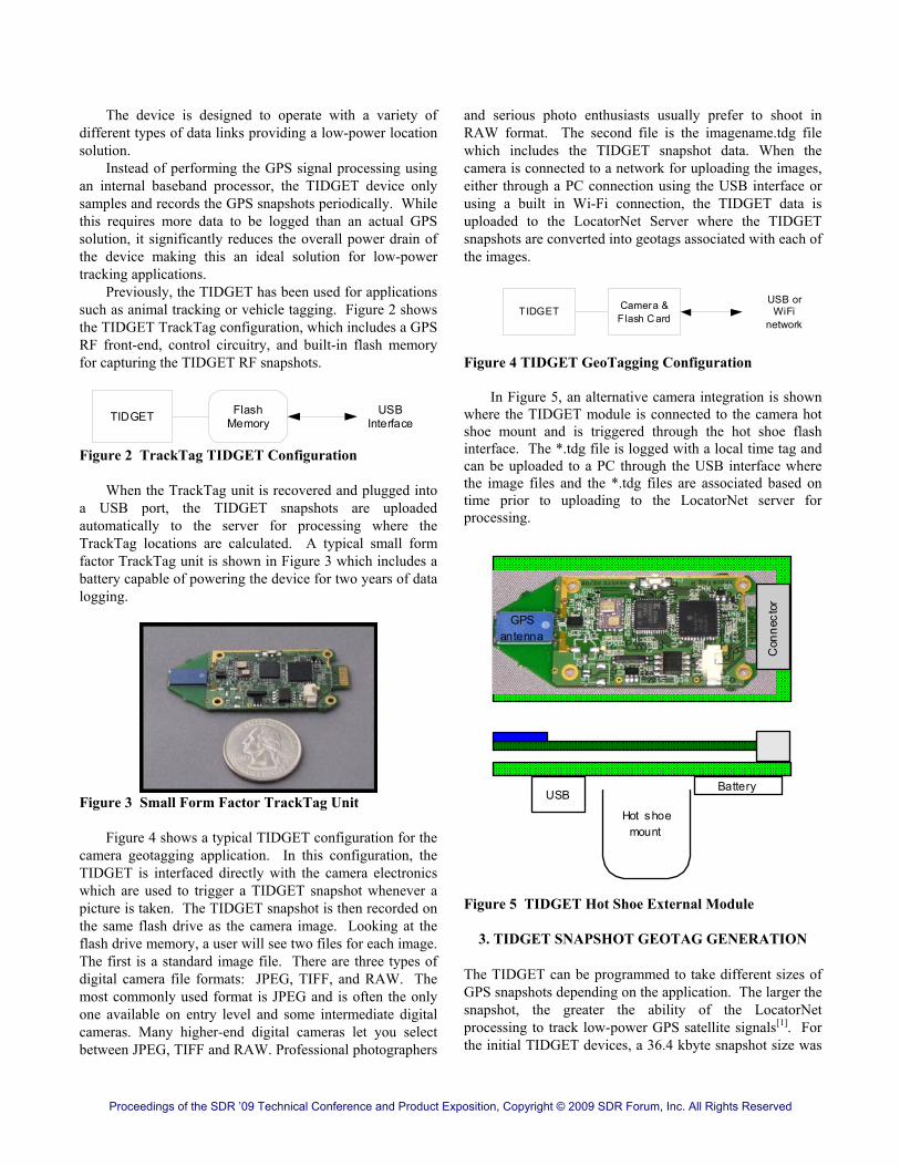
and serious photo enthusiasts usually prefer to shoot in RAW format. The second file is the imagename.tdg file which includes the TIDGET snapshot data. When the camera is connected to a network for uploading the images, either through a PC connection using the USB interface or using a built in Wi-Fi connection, the TIDGET data is uploaded to the LocatorNet Server where the TIDGET snapshots are converted into geotags associated with each of the images.
TIDGET Camera &Flash Card
USB orWiFi
network
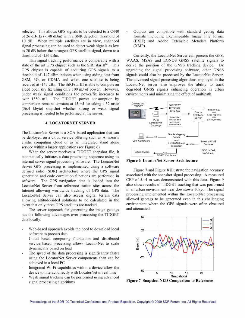
Figure 4 TIDGET GeoTagging Configuration In Figure 5, an alternative camera integration is shown where the TIDGET module is connected to the camera hot shoe mount and is triggered through the hot shoe flash interface. The *.tdg file is logged with a local time tag and can be uploaded to a PC through the USB interface where the image files and the *.tdg files are associated based on time prior to uploading to the LocatorNet server for processing.
Con
nect
or
Hot shoemount
BatteryUSB
GPSantenna
Figure 5 TIDGET Hot Shoe External Module
3. TIDGET SNAPSHOT GEOTAG GENERATION The TIDGET can be programmed to take different sizes of GPS snapshots depending on the application. The larger the snapshot, the greater the ability of the LocatorNet processing to track low-power GPS satellite signals[1]. For the initial TIDGET devices, a 36.4 kbyte snapshot size was
Proceedings of the SDR ’09 Technical Conference and Product Exposition, Copyright © 2009 SDR Forum, Inc. All Rights Reserved
selected. This allows GPS signals to be detected to a C/N0 of 26 dB-Hz (-148 dBm) with a SNR detection threshold of 10 dB. When multiple satellites are in view, enhanced signal processing can be used to detect weak signals as low as 20 dB below the strongest GPS satellite signal, down to a threshold of -156 dBm. This signal tracking performance is comparable with a state of the art GPS chipset such as the SiRFstarIII[2]. This GPS chipset is capable of acquiring GPS signals to a threshold of -147 dBm indoors when using aiding data from GSM, 3G, or CDMA and when one satellite is being received at -147 dBm. The SiRFstarIII is able to compute an aided open sky fix using only 100 mJ of power. However, under weak signal conditions the power/fix increases to over 1350 mJ. The TIDGET power consumption by comparison remains constant at 15 mJ for taking a 52 msec (36.4 kbyte) snapshot whether strong or weak signal processing is needed to be performed at the server.
4. LOCATORNET SERVER The LocatorNet Server is a SOA-based application that can be deployed on a cloud service offering such as Amazon’s elastic computing cloud or as an integrated stand alone service within a larger application (see Figure 6). When the server receives a TIDGET snapshot file, it automatically initiates a data processing sequence using its internal server signal processing software. The LocatorNet Server GPS processing is implemented using a software defined radio (SDR) architecture where the GPS signal generation and code correlation functions are performed in software. The GPS navigation data is loaded into the LocatorNet Server from reference station sites across the Internet allowing worldwide tracking of GPS data. The LocatorNet Server can also access digital terrain data allowing altitude-aided solutions to be calculated in the event that only three GPS satellites are tracked. The server approach for generating the image geotags has the following advantages over processing the TIDGET data locally: - Web-based approach avoids the need to download local
software to process data - Cloud based computing foundation and distributed
service based processing allows LocatorNet to scale dynamically based on load
- The speed of the data processing is significantly faster using the LocatorNet Server components than can be achieved in a local PC
- Integrated Wi-Fi capabilities within a device allow the device to interact directly with LocatorNet in real time
- Weak signal tracking can be performed using advanced signal processing algorithms
- Outputs are compatible with standard geotag data formats including Exchangeable Image File format (EXIF) and Adobe Extensible Metadata Platform (XMP).
Currently, the LocatorNet Server can process the GPS, WAAS, MSAS and EGNOS GNSS satellite signals to derive the position of the GNSS tracking device. By upgrading the signal processing software, other GNSS signals could also be processed by the LocatorNet Server. The advanced signal processing algorithms employed in the LocatorNet server also improves the ability to track degraded GNSS signals enhancing operation in urban environments and minimizing the effect of multipath.
PC orCamera WIFI
Gateways
GATEWAYDriver andJava App
A ssemblesTIDGET dataand inserts
into database
OracleDatabase
Server
Oracle MappingServer
andLocaterNet web
application
User Computers External WMSServices
USGS, NOAA,NASA, etc.
TIDGE T Dataand
Local mappingdata
(i .e. c it y streets)
WAN
External Apps
WAN
WANT IDGE T Web Service
Camera withTIDGET
Figure 6 LocatorNet Server Architecture Figure 7 and Figure 8 illustrate the navigation accuracy associated with the snapshot signal processing. A measured CEP of 5.14 m was demonstrated with this data. Figure 9 also shows results of TIDGET tracking that was performed in an urban environment near downtown Tokyo. The signal processing implemented within the LocatorNet processing allowed geotags to be generated even in this challenging environment where the GPS signals were often obscured and attenuated.
Figure 7 Snapshot NED Comparison to Reference

Proceedings of the SDR ’09 Technical Conference and Product Exposition, Copyright © 2009 SDR Forum, Inc. All Rights Reserved
Figure 8 Snapshot Position Solution
Figure 9 TIDGET TrackTag results in an urban environment
5. LOCATORNET SERVICE ORIENTED ARCHITECTURE (SOA)
The LocatorNet Server provides a secure repository for the TIDGET tracking data and location results preventing unauthorized access. The TIDGET geotag results are returned to the camera as conventional geotags. Geotag information is typically embedded in the meta information as EXIF-data or in some cases XMP-data. A Web-based interface, as shown in Figure 10, is also provided where a user can display the data results overlaid on a map with the associated images.
GeoTag data overlaid on
USGS WMS imagery
Figure 10 LocatorNet Server Web Display
6. TIDGET DEVELOPMENT KIT NAVSYS has developed a Development Kit for customers to evaluate the performance of the TIDGET concept and assist with integration into embedded products. The Development Kit is self-contained in a housing (see Figure 11) that comprises the following:
Figure 11 Camera TIDGET Development Unit
Proceedings of the SDR ’09 Technical Conference and Product Exposition, Copyright © 2009 SDR Forum, Inc. All Rights Reserved
1) Onboard passive mini GPS antenna with LNA, optional H-FL connector for external active antenna
2) GPS RF downconvertor module, with onboard precision TCXO. Output is serial digital data stream.
3) Custom microcontroller/CPLD/Flash interface for logging GPS data
4) USB interface and battery (device initialization, battery charging and data download).
The unit has 4Gbyte of Flash memory (typically 128,000 position fix capability), consumes 50mA for 50 mSecs from the battery per position fix, and draws 2.5 uA when in standby. The unit is initialized and downloaded using a supplied utility via USB to a laptop. The device automatically takes a GPS snapshot synchronous with the flash trigger associated with taking of a picture. The Development Kit is intended as a means for a customer to evaluate the performance of the GPS unit and TIDGET signal processing in a representative environment. The flexibility in the GPS antenna choice permits evaluation of various antenna options prior to any decision being made regarding final integration. The individual components from the Development Kit that would need to be integrated into an eventual customer product may be as simple as the GPS antenna and front-end module, depending on the resources available to the host system microcontroller and non-volatile memory system.
7. CONCLUSION
In summary, the TIDGET solution has the following advantages for geotagging applications that require low power operations, such as an embedded digital camera solution. • Low cost solution using proven COTS RF components • Small form-factor, ultra-low power design • Instant-on data capture (no start-up time required) • All-in-view tracking with multiple GNSS systems • Operation in weak GNSS signal environments • Fast signal processing using LocatorNet Server • Automated geotag meta-data generation through
Internet services • Compatible outputs with major Web-based image
viewing services such as Google's Picasa and Yahoo's Flickr Development.
8. REFERENCES
[1] A. Brown, J. Griesbach, B. Bockius and T. Boult, “GPS Tracking Location-Based Service Using Wristwatch GeoZigBee Sensors,” Proceedings of the ION National Technical Meeting 2007, San Diego, CA, January 2007.
[2] http://www.sirf.com/Downloads/Collateral/GSC3(f)_ 6.20.05.pdf
Copyright Transfer Agreement: The following Copyright Transfer Agreement must be included on the cover sheet for the paper (either email or fax)—not on the paper itself. “The authors represent that the work is original and they are the author or authors of the work, except for material quoted and referenced as text passages. Authors acknowledge that they are willing to transfer the copyright of the abstract and the completed paper to the SDR Forum for purposes of publication in the SDR Forum Conference Proceedings, on associated CD ROMS, on SDR Forum Web pages, and compilations and derivative works related to this conference, should the paper be accepted for the conference. Authors are permitted to reproduce their work, and to reuse material in whole or in part from their work; for derivative works, however, such authors may not grant third party requests for reprints or republishing.” Government employees whose work is not subject to copyright should so certify. For work performed under a U.S. Government contract, the U.S. Government has royalty-free permission to reproduce the author's work for official U.S. Government purposes.