brocade silkworm switches (5092) - ehealth...
TRANSCRIPT

Brocade Silkworm Switches
Device Management
Supports Management Module SM-BRC1000

D e v i c e M a n a g e m e n t Page 2 B r o c a d e S i l k w o r m S w i t c h e s
Copyright NoticeDocument 9035092. Copyright © March 2002 by Aprisma Management Technologies, Inc. All rights reserved worldwide. Use, duplication, or disclosure by the United States government is subject to the restrictions set forth in DFARS 252.227-7013(c)(1)(ii) and FAR 52.227-19.Liability DisclaimerAprisma Management Technologies, Inc. (“Aprisma”) reserves the right to make changes in specifications and other information contained in this document without prior notice. In all cases, the reader should contact Aprisma to inquire if any changes have been made.
The hardware, firmware, or software described in this manual is subject to change without notice.
IN NO EVENT SHALL APRISMA, ITS EMPLOYEES, OFFICERS, DIRECTORS, AGENTS, OR AFFILIATES BE LIABLE FOR ANY INCIDENTAL, INDIRECT, SPECIAL, OR CONSEQUENTIAL DAMAGES WHATSOEVER (INCLUDING BUT NOT LIMITED TO LOST PROFITS) ARISING OUT OF OR RELATED TO THIS MANUAL OR THE INFORMATION CONTAINED IN IT, EVEN IF APRISMA HAS BEEN ADVISED OF, HAS KNOWN, OR SHOULD HAVE KNOWN, THE POSSIBILITY OF SUCH DAMAGES.
Trademark, Service Mark, and Logo InformationSPECTRUM, IMT, and the SPECTRUM IMT/VNM logo are registered trademarks of Aprisma Management Technologies, Inc., or its affiliates. APRISMA, APRISMA MANAGEMENT TECHNOLOGIES, the APRISMA MANAGEMENT TECHNOLOGIES logo, MANAGE WHAT MATTERS, DCM, VNM, SpectroGRAPH, SpectroSERVER, Inductive Modeling Technology, Device Communications Manager, SPECTRUM Security Manager, and Virtual Network Machine are unregistered trademarks of Aprisma Management Technologies, Inc., or its affiliates. For a complete list of Aprisma trademarks, service marks, and trade names, go tohttp://www.aprisma.com/manuals/trademark-list.htm.
All referenced trademarks, service marks, and trade names identified in this document, whether registered or unregistered, are the intellectual property of their respective owners. No rights are granted by Aprisma Management Technologies, Inc., to use such marks, whether by implication, estoppel, or otherwise. If you have comments or concerns
about trademark or copyright references, please send an e-mail to [email protected]; we will do our best to help.
Restricted Rights Notice(Applicable to licenses to the United States government only.)This software and/or user documentation is/are provided with RESTRICTED AND LIMITED RIGHTS. Use, duplication, or disclosure by the government is subject to restrictions as set forth in FAR 52.227-14 (June 1987) Alternate III(g)(3) (June 1987), FAR 52.227-19 (June 1987), or DFARS 52.227-7013(c)(1)(ii) (June 1988), and/or in similar or successor clauses in the FAR or DFARS, or in the DOD or NASA FAR Supplement, as applicable. Contractor/manufacturer is Aprisma Management Technologies, Inc. In the event the government seeks to obtain the software pursuant to standard commercial practice, this software agreement, instead of the noted regulatory clauses, shall control the terms of the government's license.Virus DisclaimerAprisma makes no representations or warranties to the effect that the licensed software is virus-free.
Aprisma has tested its software with current virus-checking technologies. However, because no antivirus system is 100 percent effective, we strongly recommend that you write-protect the licensed software and verify (with an antivirus system in which you have confidence) that the licensed software, prior to installation, is virus-free.
Contact InformationAprisma Management Technologies, Inc.273 Corporate DrivePortsmouth, NH 03801Phone: 603-334-2100U.S. toll-free: 877-468-1448Web site: http://www.aprisma.com

D e v i c e M a n a g e m e n t Page 3 B r o c a d e S i l k w o r m S w i t c h e s
ContentsINTRODUCTION 4
Purpose and Scope ........................................................4Required Reading ...........................................................4Supported Devices..........................................................5The SPECTRUM Model ..................................................5
TASKS 7
DEVICE VIEW 8
Interface Icons ................................................................9Interface Icon Subviews Menu......................................10Secondary Address Panel ............................................11
DEVICE TOPOLOGY VIEW 12
SWITCHING INFORMATION 13
System Information View ..............................................13Environment Information View ......................................17Fabric Information View ................................................17Agent Community Information View..............................18Fibre Channel Port Information View ............................18Name Server Information View .....................................22FW Thresholds Information View..................................23FW Class Area Information View ..................................24Event Information View .................................................25End Devices RLS Information View ..............................25
Bloom Performance Alpa Information View .................. 26Bloom Performance End to End Performance View.....26Bloom Performance Filter Base Information View ........ 27Trunking Information View ............................................ 28Trunk Group Information............................................... 28
APPLICATION VIEWS 29
Main Application View................................................... 29Supported Applications ................................................. 30
Common Applications ............................................... 30Device-Specific MIBs ................................................ 31
PERFORMANCE VIEWS 32
CONFIGURATION VIEWS 33
Device Configuration View............................................ 33
MODEL INFORMATION VIEW 35
TRAPS, EVENTS, AND ALARMS 36
Standard Trap Support ................................................. 36Device-Specific Trap Support ....................................... 36
Proprietary Trap Descriptions.................................... 38
INDEX 39
D e v i c e M a n a g e m e n t Page 4 B r o c a d e S i l k w o r m S w i t c h e s
Introduction
This section introduces the SPECTRUM Device Management documentation for the Brocade Silkworm Switch.
This introduction contains the following topics:
• Purpose and Scope
• Required Reading
• Supported Devices (Page 5)
• The SPECTRUM Model (Page 5)
Purpose and ScopeUse this document as a guide for managing the Brocade Silkworm Switch devices described on Page 5 with SPECTRUM management module SM-BRC1000. This document describes the icons, menus, and views that enable you to remotely monitor, configure, and troubleshoot Brocade Silkworm Switch devices through software models in your SPECTRUM database.
Information specific to SM-BRC1000 is what is primarily included in this document. For general information about device management using SPECTRUM and explanations of SPECTRUM
functionality and navigation techniques, refer to the topics listed under Required Reading.
Required ReadingTo use this documentation effectively, you must be familiar with the information covered by the other SPECTRUM online documents listed below.
• Getting Started with SPECTRUM for Operators
• Getting Started with SPECTRUM for Administrators
• How to Manage Your Network with SPECTRUM
• SPECTRUM Views
• SPECTRUM Menus
• SPECTRUM Icons
• SPECTRUM Software Release Notice

I n t r o d u c t i o n S u p p o r t e d D e v i c e s
D e v i c e M a n a g e m e n t Page 5 B r o c a d e S i l k w o r m S w i t c h e s
Supported DevicesSPECTRUM management module SM-BRC1000 currently lets you model the following Brocade Silkworm Switch.
• SilkWorm 2010 8 port Entry-level Fibre Channel Switch
• SilkWorm 2040 8 port Entry-level Fibre Channel Switch
• SilkWorm 2050 8 port Entry-level Fibre Channel Switch
• SilkWorm 2210 16 port Entry-level Fibre Channel Switch
• SilkWorm 2240 16 port Entry-level Fibre Channel Switch
• SilkWorm 2250 16 port Entry-level Fibre Channel Switch
• SilkWorm 2400 8 port Fibre Channel Switch • SilkWorm 2800 16 port Fibre Channel Switch • SilkWorm 3200 Entry Fabric Switch• SilkWorm 3800 Enterprise Fabric Switch• SilkWorm 3900 Enterprise Fabric Switch• SilkWork 12000 Director
The SPECTRUM ModelThe model type for the Brocade Silkworm Switch devices is SilkwormSw.
Modeling results in the creation of Device icons that represent the devices and Application icons that represent their supported applications.
The Device icons contain double-click zones and provide access to Icon Subviews menus that let you perform device management activities such as those listed in Tasks on Page 7.
As Figure 1 shows, the appearance of the Device icons varies slightly depending on the kind of view it appears in.
Figure 1: Device Icons
Model Name
XYZ_Mxxx
Model Name
XYZ_Mxxx
Small Device icon appears inTopology and Application views
Large Device icon appears inDevice Topology, Location, andDevice Interface views.

I n t r o d u c t i o n T h e S P E C T R U M M o d e l
D e v i c e M a n a g e m e n t Page 6 B r o c a d e S i l k w o r m S w i t c h e s
The device-specific Icon Subviews menu options available from the Device icon are listed below.
The rest of this document covering management module SM-BRC1000 is organized as follows:
• Tasks (Page 7)
• Device View (Page 8)
• Device Topology View (Page 12)
• Application Views (Page 29)
• Performance Views (Page 32)
• Configuration Views (Page 33)
• Model Information View (Page 35).
Option Accesses the...
Fault Management
Fault Management view, which is described in the How to Manage Your Network with SPECTRUM documentation.
Device Device View (Page 8)
Device Topology Device Topology View (Page 12)
Application Application Views (Page 29)
Configuration Configuration Views (Page 33)
Model Information
Model Information View (Page 35)
Primary Application
Menu options that let you select either Gen. Bridge App or MIB-II as the primary application.

D e v i c e M a n a g e m e n t Page 7 B r o c a d e S i l k w o r m S w i t c h e s
Tasks
This section contains an alphabetical list of device management tasks, with each task providing one or more links to views that let you perform the task.
Administrative Information (check)• Model Information View (Page 35)
Alarm Thresholds (set)• Interface Icon Subviews Menu (Page 10)
Configuration Information (check)• Configuration Views (Page 33)
IP Address (find/change)• Device View (Page 8)• Secondary Address Panel (Page 11)
Network Type (check)• Network Type Label (Page 10)
Performance (check)• Device View (Page 8)• Interface Icons (Page 9)• Performance Views (Page 32)
Port Status (check/change)• Secondary Address Panel (Page 11)
Topology (check)• Device Topology View (Page 12)

D e v i c e M a n a g e m e n t Page 8 B r o c a d e S i l k w o r m S w i t c h e s
Device View
This section describes the Device view and subviews available for models of Brocade Silkworm Switch devices in SPECTRUM.
Access: From the Icon Subviews menu for the Device icon, select Device > Interface.
This view (Figure 2) uses icons and labels to represent the device and its components, such as modules, ports, and applications. The view provides dynamic configuration and performance information for each of the device’s serial and network I/O ports, which are represented by Interface icons in the bottom panel of the view. The middle panel of the view displays a Device icon, which lets you monitor the device operation and access other device-specific views.
Figure 2: Device View
SpectroGRAPH: Router Device: Model Name
File View HelpTools
Model NameContactDescriptionLocation
Sys Up TimeManufacturerDevice TypeSerial Number
Network Address
Interface Description
Filter Physical
Interface Options PanelDevice Icon
XYZ_Mxxx
Model Name
1Ethernet
0:0:1D:F:FD:B6
ei0
0.0.0.0
ON
5SFTWARLPBK
0:0:1D:F:FD:B6
lo0
0.0.0.0
ON
9ATM8023
0:0:1D:F:FD:B6
zn1
0.0.0.0
ON
512AAL5
UAAL5
0.0.0.0
ON
2ATMCPU
0.0.0.0
ON
6ATM portCPU.1
0.0.0.0
ON
ATM7A1
0.0.0.0
ON
ATM7B1
0.0.0.0
ON
ATM7B2
0.0.0.0
ON
ATM7B3
0.0.0.0
ON
ATM8B1
0.0.0.0
ON
ATM8B2
0.0.0.0
ON
ATM8B3
0.0.0.0
ON
ATM8B4
0.0.0.0
ON
10
2783905 2783909
11
7
3 4
8
Interface Icons
Bookmarks
Model Name of type XYZ_Mxxx of Landscape node: Primary
Primary Application Gen Bridge App

D e v i c e V i e w I n t e r f a c e I c o n s
D e v i c e M a n a g e m e n t Page 9 B r o c a d e S i l k w o r m S w i t c h e s
Interface IconsFigure 3 shows a close-up of an Interface icon from the Device view. Most of the informational labels on the icon also provide double-click access to other views, as explained in the following label descriptions.
Figure 3: Interface Icon
Interface Number LabelThis label displays the interface (port) number.
IF Status LabelThis label displays the current status of the interface for the primary application selected, e.g., Gen Rtr App or MIB-II App. Table 1 lists the possible label color representations. Note that the color of the label also depends on the interface’s current Administrative Status, which you set in the Interface Configuration view. This view can be accessed by double-clicking the Interface Type label.
Interface Type LabelThis label identifies the interface type (Ethernet, ATM, etc.). Double-click this label to access the Interface Device view, see the SPECTRUM Views documentation.
c
f
b
1ethernet
0:0:1D:F:FD:B6
a
a Interface Number Label
b IF Status Label
c Interface Type Label
d Network Type Label
e Physical Address Label
f IP Address Label
fxp0
0.0.0.0
d
e
ONTable 1: Interface Status Label Colors
ColorOperational
StatusAdministrative
StatusLabelText
Green up up ON
Blue down down OFF
Yellow down up OFF
Red testing testing TEST
D e v i c e V i e w I n t e r f a c e I c o n S u b v i e w s M e n u
D e v i c e M a n a g e m e n t Page 10 B r o c a d e S i l k w o r m S w i t c h e s
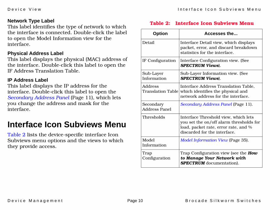
Network Type LabelThis label identifies the type of network to which the interface is connected. Double-click the label to open the Model Information view for the interface.
Physical Address LabelThis label displays the physical (MAC) address of the interface. Double-click this label to open the IF Address Translation Table.
IP Address LabelThis label displays the IP address for the interface. Double-click this label to open the Secondary Address Panel (Page 11), which lets you change the address and mask for the interface.
Interface Icon Subviews MenuTable 2 lists the device-specific interface Icon Subviews menu options and the views to which they provide access.
Table 2: Interface Icon Subviews Menu
Option Accesses the...
Detail Interface Detail view, which displays packet, error, and discard breakdown statistics for the interface.
IF Configuration Interface Configuration view. (See SPECTRUM Views).
Sub-Layer Information
Sub-Layer Information view. (See SPECTRUM Views).
Address Translation Table
Interface Address Translation Table, which identifies the physical and network address for the interface.
Secondary Address Panel
Secondary Address Panel (Page 11).
Thresholds Interface Threshold view, which lets you set the on/off alarm thresholds for load, packet rate, error rate, and % discarded for the interface.
Model Information
Model Information View (Page 35).
Trap Configuration
Trap Configuration view (see the How to Manage Your Network with SPECTRUM documentation).

D e v i c e V i e w S e c o n d a r y A d d r e s s P a n e l
D e v i c e M a n a g e m e n t Page 11 B r o c a d e S i l k w o r m S w i t c h e s
Secondary Address PanelAccess: From the Icon Subviews menu for the Interface icon in the Device view, select Secondary Address Panel.
This panel provides a table of IP addresses and masks obtained from the Address Translation table within the device’s firmware. You can change the current address displayed in the IP Address field by selecting an entry from the table in this panel and clicking the Update button.

D e v i c e M a n a g e m e n t Page 12 B r o c a d e S i l k w o r m S w i t c h e s
Device Topology View
This section describes the Device Topology view available for models of the Brocade Silkworm Switch devices.
Access: From the Icon Subviews menu for the Device icon, select DevTop > interface.
The Device Topology view (Figure 4) shows the connections between a modeled device and other network entities. The lower panel of the view uses Interface icons to represent the device’s serial, network, and I/O ports. These icons provide the same information and menu options as those in the Device View (Page 8). If a device is connected to a particular interface, a Device icon appears on the vertical bar above the Interface icon along with an icon representing the network group that contains the device.
Refer to the SPECTRUM Views documentation for details on Device Topology view.
Figure 4: Device Topology View
File View HelpTools
1Ethernet
0:0:1D:F:FD:B6ei0
0.0.0.0
ON 2ATM
0:0:1D:F:FD:B6A2
0.0.0.0
ON 3ATM
0:0:1D:F:FD:B6CPU
0.0.0.0
ON
XYZ_Mxxx
Model Name
Bookmarks
SpectroGRAPH: Device Topology: Model Name
Graphic of<manufacturer>
Device
Model Name of type Model Type of Landscape node: Primary

D e v i c e M a n a g e m e n t Page 13 B r o c a d e S i l k w o r m S w i t c h e s
Switching Information
This section describes the switching information available for the Brocade Silkworm devices.
The following views provide switching information for the Brocade Silkworm devices:
• System Information View (Page 13)• Environment Information View (Page 17)• Fabric Information View (Page 17)• Agent Community Information View (Page 18)• Fibre Channel Port Information View (Page 18)• Name Server Information View (Page 22)• FW Thresholds Information View (Page 23)• FW Class Area Information View (Page 24)• Event Information View (Page 25)• End Devices RLS Information View (Page 25)• Bloom Performance Alpa Information View
(Page 26)• Bloom Performance End to End Performance
View (Page 26)• Bloom Performance Filter Base Information
View (Page 27)• Trunking Information View (Page 28)• Trunk Group Information (Page 28)
System Information ViewAccess: From the Icon Subviews menu for the Device icon, select Switch Information > System.
This view is divided into four separate sections and provides the following information.
General Information
Firmware Vers.The current version of the firmware.
Soft Ser. Num.The serial number of the software.
Oper StatusThe current operational status of the switch. Table 3 displays the possible states.

S w i t c h i n g I n f o r m a t i o n S y s t e m I n f o r m a t i o n V i e w
D e v i c e M a n a g e m e n t Page 14 B r o c a d e S i l k w o r m S w i t c h e s
Telnet Admin StatusThe desired administrative status of the Telnet shell. By setting it to terminated, the current Telnet shell task is deleted. When this variable is read, it reports the value last set through SNMP.
Admin StatusThe desired administrative status of the switch. A management station may place the switch in a desired state by setting this button accordingly. Table 4 defines the possible states.
.
Track Changes StringDisplays the track changes string. This is for traps only.
Table 3: Possible Operational States
State Definition
Online The switch is accessible by an external Fibre Channel Port.
Offline The switch is not accessible.
Testing The switch is in a built-in test mode and is not accessible.
Faulty The switch is not operational.
Table 4: Admin Status States
Sate Definition
Online This switch is accessible by a an external Fiber Channel Port.
Offline The switch is not accessible.
Testing The switch is in a built-in test mode and is not accessible.
Faulty The switch is not operational.
Reboot Set the switch to reboot in one second.
Fastboot Sets the switch to fastboot in one second. Fast causes the switch to boot but skip over the POST.
S w i t c h i n g I n f o r m a t i o n S y s t e m I n f o r m a t i o n V i e w
D e v i c e M a n a g e m e n t Page 15 B r o c a d e S i l k w o r m S w i t c h e s
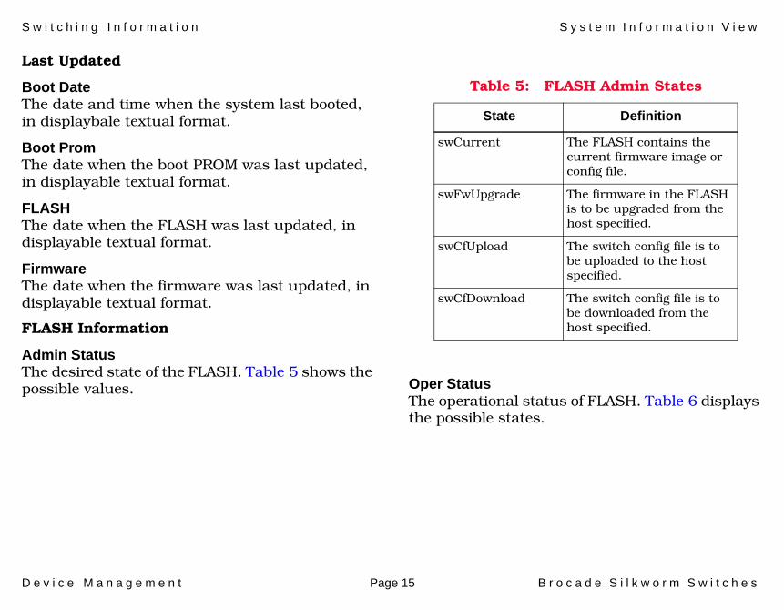
Last Updated
Boot DateThe date and time when the system last booted, in displaybale textual format.
Boot PromThe date when the boot PROM was last updated, in displayable textual format.
FLASHThe date when the FLASH was last updated, in displayable textual format.
FirmwareThe date when the firmware was last updated, in displayable textual format.
FLASH Information
Admin StatusThe desired state of the FLASH. Table 5 shows the possible values. Oper Status
The operational status of FLASH. Table 6 displays the possible states.
Table 5: FLASH Admin States
State Definition
swCurrent The FLASH contains the current firmware image or config file.
swFwUpgrade The firmware in the FLASH is to be upgraded from the host specified.
swCfUpload The switch config file is to be uploaded to the host specified.
swCfDownload The switch config file is to be downloaded from the host specified.

S w i t c h i n g I n f o r m a t i o n S y s t e m I n f o r m a t i o n V i e w
D e v i c e M a n a g e m e n t Page 16 B r o c a d e S i l k w o r m S w i t c h e s
PasswordThe password to be used for FTP transfer of files in the download or upload operation.
UserThe user name on the host to download or upload a relevant file to or from the FLASH.
HostThe name or IP address (in dot notation) of the host to download or upload a relevant file to the FLASH.
FileThe name of the file to be downloaded or uploaded.
Misc Information
POST ResultThe result of the power-on startup (POST) diagnostics.
SensorsThe number of sensors inside the switch.
Beacon Admin StatusThe desired status of the switch beacon. When the beacon is set to on, the LEDs on the front panel of the switch run alternately from left to right and right to left. The color is yellow. When the beacon is set to off, each LED will be in its regular status indicating color and state.
Beacon Oper StatusThe current operational status of the switch beacon. When the beacon is on, the LEDs on the front panel of the switch run alternately from left to right and right to left. The color is yellow. When the beacon is off, each LED will be in their its regular status indicating color and state.
Table 6: FLASH Operational States
State Definition
swCurrent The FLASH contains the current firmware image or config file.
swFwUpgraded Contains the image upgraded from the swFlashDLHost.0.
swCfUploaded The switch configuration file has been uploaded to the host.
swCfDownloaded The switch configuration file has been downloaded from the host.

S w i t c h i n g I n f o r m a t i o n E n v i r o n m e n t I n f o r m a t i o n V i e w
D e v i c e M a n a g e m e n t Page 17 B r o c a d e S i l k w o r m S w i t c h e s
Environment Information ViewAccess: From the Icon Subviews menu for the Device icon, select Switch Information > Environment.
This view provides the Sensor Table and the following information.
Num SensorThe number of sensors inside the switch.
Sensor Table
IndexIdentifies the sensor.
TypeIdentifies the sensor type.
StatusThe current status of the sensor.
ValueThe current value (reading) of the sensor. The value, -2147483648, represents an unknown quantity. It also means that the sensor does not have the capability to measure the actual value. In V2.0, the temperature sensor value will be in Celsius; the fan value will be in RPM (revolution per minute); and the power supply sensor reading will be unknown.
InfoAdditional displayable information on the sensor. In V2.x, it contains the sensor type and number in textual format.
Fabric Information ViewAccess: From the Icon Subviews menu for the Device icon, select Switch Information > Fabric.
This view provides the following information.
Domain IDThe current Fibre Channel domain ID of the switch. To set a new value, the switch (swAdmStatus) must be in offline or testing state.
Principal SwitchIndicates whether the switch is the Principal switch as per FC-SW.
Num NeighborsThe number of Inter-Switch Links in the (immediate) neighborhood.
Neighbor Table
IndexIdentifies the neighbor ISL entry.
Local PortThis is a port that has an ISL to another switch.

S w i t c h i n g I n f o r m a t i o n A g e n t C o m m u n i t y I n f o r m a t i o n V i e w
D e v i c e M a n a g e m e n t Page 18 B r o c a d e S i l k w o r m S w i t c h e s
Remote DomainThe Fibre Channel domain on the other end of the ISL.
Remote PortThe port index on the other end of the ISL.
Baud RateThe baud rate of the ISL.
StateThe current state of the ISL.
CostThe current link cost of the ISL.
Remote NameThe World_wide_Name of the remote port.
Agent Community Information ViewAccess: From the Icon Subviews menu for the Device icon, select Switch Information > Agent Comm.
This view provides the following information.
Agent Community IndexIdentifies the SNMPv1 Community entry.
Agent Community StringThe Community string supported by the agent. If a new value is set successfully, it takes effect immediately.
Agent Trap RecipientThe trap recipient associated with the Community. If a new value is set successfully, it takes effect immediately.
Fibre Channel Port Information ViewAccess: From the Icon Subviews menu for the Device icon, select Switch Information > FC Ports.
This view provides the Port Table defined below:
Port CapacityThe maximum number of Fibre Channel ports on this switch. It includes G_Port, F_Port, FL_Port and any other types of Fibre Channel port.
IndexIdentifies the switch port index. Note that the value of a port index is 1 higher than the port number labeled on the front panel. E.g. port index 1 correspond to port number 0.
S w i t c h i n g I n f o r m a t i o n F i b r e C h a n n e l P o r t I n f o r m a t i o n V i e w
D e v i c e M a n a g e m e n t Page 19 B r o c a d e S i l k w o r m S w i t c h e s
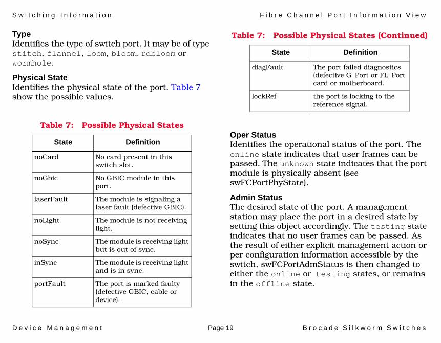
TypeIdentifies the type of switch port. It may be of type stitch, flannel, loom, bloom, rdbloom or wormhole.
Physical StateIdentifies the physical state of the port. Table 7 show the possible values.
Oper StatusIdentifies the operational status of the port. The online state indicates that user frames can be passed. The unknown state indicates that the port module is physically absent (see swFCPortPhyState).
Admin StatusThe desired state of the port. A management station may place the port in a desired state by setting this object accordingly. The testing state indicates that no user frames can be passed. As the result of either explicit management action or per configuration information accessible by the switch, swFCPortAdmStatus is then changed to either the online or testing states, or remains in the offline state.
Table 7: Possible Physical States
State Definition
noCard No card present in this switch slot.
noGbic No GBIC module in this port.
laserFault The module is signaling a laser fault (defective GBIC).
noLight The module is not receiving light.
noSync The module is receiving light but is out of sync.
inSync The module is receiving light and is in sync.
portFault The port is marked faulty (defective GBIC, cable or device).
diagFault The port failed diagnostics (defective G_Port or FL_Port card or motherboard.
lockRef the port is locking to the reference signal.
Table 7: Possible Physical States (Continued)
State Definition

S w i t c h i n g I n f o r m a t i o n F i b r e C h a n n e l P o r t I n f o r m a t i o n V i e w
D e v i c e M a n a g e m e n t Page 20 B r o c a d e S i l k w o r m S w i t c h e s
Link StateThe link state of the port. The possible value are: enabled, disabled, and loopback. The port may transmit frames through an internal path to verify the health of the transmitter and receiver path.
TX TypeThe media transmitter type of the port. Table 8 show the possible values.
TX WordsCounts the number of Fibre Channel words that the port has transmitted.
RX WordsCounts the number of Fibre Channel words that the port has received.
TX FramesCounts the number of (Fibre Channel) frames that the port has transmitted.
RX FramesCounts the number of (Fibre Channel) frames that the port has received.
RX C2 FramesCounts the number of Class 2 frames that the port has received.
RX C3 FramesCounts the number of Class 3 frames that the port has received.
RX LCsCounts the number of Link Control frames that the port has received.
RX McastsCounts the number of Multicast frames that the port has received.
Table 8: Possible TX States
State Definition
unknown Cannot determine the port driver.
lw Long wave laser.
sw Short wave laser.
ld Long wave LED.
cu Copper Electral.
Note:Note:
Not that here is a new type of GBIC which has a serial ID and will be mapped as unknown for the current firmware revision.

S w i t c h i n g I n f o r m a t i o n F i b r e C h a n n e l P o r t I n f o r m a t i o n V i e w
D e v i c e M a n a g e m e n t Page 21 B r o c a d e S i l k w o r m S w i t c h e s
Too Many RDYsCounts the number of times when RDYs exceeds the frames received.
No Tx CreditsCounts the number of times when the transmit credit has reached zero.
RX Enc In FrsCounts the number of encoding error or disparity error inside frames received.
Rx CRCsCounts the number of CRC errors detected for frames received.
RX TruncsCounts the number of truncated frames that the port has received.
RX Too LongsCounts the number of received frames that are too long.
Rx Bad EOFsCounts the number of received frames that have bad EOF delimiter.
RX Enc Out FrsCounts the number of encoding error or disparity error outside frames received
RX Bad OsCounts the number of invalid Ordered Sets received.
C3 DiscardsCounts the number of Class 3 frames that the port has discarded.
Tx McastsCounts the number of Multicast frames that has been transmitted.
Mcasts Time OutsCounts the number of Multicast frames that has been timed out.
Lip InsCounts the number of Loop Initialization that has been initiated by loop devices attached.
Lip OutsCounts the number of Loop Initializations that has been initiated by the port.
Lips Last AlpaThe Physical Address (AL_PA) of the loop device that initiated the last Loop Initialization.
World Wide NameThe World_Wide_Name of the Fibre Channel port. The contents of an instance are in the IEEE extended format as specified in FC-PH; the 12-bit

S w i t c h i n g I n f o r m a t i o n N a m e S e r v e r I n f o r m a t i o n V i e w
D e v i c e M a n a g e m e n t Page 22 B r o c a d e S i l k w o r m S w i t c h e s
port identifier represents the port number within the switch.
Port SpeedThe desired baud rate for the port. It can have the values of 1GB(1), 2GB (2) or Auto-Negotiate (3).
Name Server Information ViewAccess: From the Icon Subviews menu for the Device icon, select Switch Information > Name Server.
This view provides the following information.
IndexThe Name Server database entry.
Port IDThe Fibre Channel port address.
Port TypeThe type of port. N_Port, NL_Port, etc., for this entry. The type is defined in FC-GS-2.
Port NameThe Fibre Channel World_Wide Name of the port entry.
Port SymbolThe contents of a Symbolic Name of the port entry. In FC-GS-2, a Symbolic Name consists of a byte array of 1 through 256 bytes, and the first byte of the array specifies the length of its
contents. This variable corresponds to the 'contents of the Symbolic Name, without the first byte.
Node NameThe Fibre Channel World_Wide Name of the associated node as defined in FC-GS-2.
Node SymbolThe contents of a Symbolic Name of the node associated with the entry. In FC-GS-2, a Symbolic Name consists of a byte array of 1 through 256 bytes, and the first byte of the array specifies the length of its contents. This variable corresponds to the contents of the Symbolic Name, without the first byte (specifying the length).
IPAThe Initial Process Associator of the node for the entry as defined in FC-GS-2.
IP AddressThe IP address of the node for the entry as defined in FC-GS-2. The format of the address is in IPv6.
COSThe class of services supported by the port. The value is a bit-map defined as follows: 0 is class F, 1 is class 1, and 2 is class 2 etc.

S w i t c h i n g I n f o r m a t i o n F W T h r e s h o l d s I n f o r m a t i o n V i e w
D e v i c e M a n a g e m e n t Page 23 B r o c a d e S i l k w o r m S w i t c h e s
FC-4sThe FC-4s supported by the port as defined in FC-GS-2.
IP Nx_PortIpAddress of the Nx_port for the entry.
World Wide NameThe World Wide Name (WWN) of the Fx_port for the entry.
Hard AddressThe 24-bit hard address of the node for the entry.
FW Thresholds Information ViewAccess: From the Icon Subviews menu for the Device icon, select Switch Information > FW Thresholds.
This view provides the following information.
IndexAn entry for each threshold in this table.
StatusIdentifies if a threshold is enabled or disabled
NameThe name of the threshold.
LabelLabel of the threshold.
Current ValA current counter of the threshold.
Last EventThe last event type of the threshold.
Last Event TimeThe last event value of the threshold.
Last StateThe last event time of the threshold
Behavior TypeA behavior of which the thresholds generate events.
Behavior IntAn integer of which the thresholds generate continuous events.

S w i t c h i n g I n f o r m a t i o n F W C l a s s A r e a I n f o r m a t i o n V i e w
D e v i c e M a n a g e m e n t Page 24 B r o c a d e S i l k w o r m S w i t c h e s
FW Class Area Information ViewAccess: From the Icon Subviews menu for the Device icon, select Switch Information > FW Class.
This view provides the following information.
Class Area IndexThe class type.
Write Thresh ValsApplies the value changes.
Default UnitA Default unit string name for a threshold area.
Default TimebaseA Default timebase for the current threshold counter.
Default LowA Default low threshold value.
Default HighA Default high threshold value.
Default Buf SizeA Default buffer size value.
Cust UnitA custom unit string name for a threshold area.
Cust TimebaseA custom timebase for the current threshold counter.
Cust LowA custom low threshold value.
Cust HighA custom high threshold value.
Cust Buf SizeA custom buffer size value.
Thresh LevelA level where all the threshold values are set at.
Write Act ValsSwFwis is set to apply act value changes.
Default Changed ActsDefault action matrix for changed event.
Default Exceed ActsDefault action matrix for exceeded event.
Default Below ActsDefault action matrix for below event.
Default Above ActsDefault action matrix for above event.
Default In Between ActsDefault action matrix for in-between event.

S w i t c h i n g I n f o r m a t i o n E v e n t I n f o r m a t i o n V i e w
D e v i c e M a n a g e m e n t Page 25 B r o c a d e S i l k w o r m S w i t c h e s
Cust Changed ActsCustom action matrix for changed event.
Cust Exceeded ActsCustom action matrix for exceeded event.
Cust Below ActsCustom action matrix for below event.
Cust Above ActsCustom action matrix for above event.
Cust in Between ActsCustom action matrix for in-between event.
Valid ActsMatrix of valid acts for an class/area
Act LevelA level where all the actions are set.
Event Information ViewAccess: From the Icon Subviews menu for the Device icon, select Switch Information > Events.
This view provides the following information.
Number of EntriesThe number of entries in the Event Table.
Event IndexThe event entry.
Event Time InfoThe date and time when this event occurred, in textual format.
Event LevelThe severity level of this event entry.
Event Repeat CountHow many times this particular event has occurred.
Event DescrThe textual description of the event.
End Devices RLS Information ViewAccess: From the Icon Subviews menu for the Device icon, select Switching Information > End Devices.
This view provides the following information.
PortThe port number of the end device.
AlpaThe alpa of the end device.

S w i t c h i n g I n f o r m a t i o n B l o o m P e r f o r m a n c e A l p a I n f o r m a t i o n V i e w
D e v i c e M a n a g e m e n t Page 26 B r o c a d e S i l k w o r m S w i t c h e s
Post IDThe Fibre Channel port address.
Link Fail CountLink failure count for the end device.
Sync Loss CountSync loss count for the end device.
Sig Loss CountSig loss count for the end device.
Proto Error CountProtocol error count for the end device.
Invalid Word CountInvalid word count for the end device.
Invalid CRC CountInvalid CRC count for the end device.
Bloom Performance Alpa Information ViewAccess: From the Icon Subviews menu for the Device icon, select Switch Information > Bloom Perf Alpa.
This view provides the following information.
Alpa PortThe port index of the switch.
Alpa IndexThe ALPA index. There can be 126 ALPA values.
AlpaThe ALPA values. These values range between x01 and x'EF(1 to 239). ALPA value x'00' is reserved for FL_Port If Alpa device is invalid, then it will have -1 value.
Alpa CRC CountGet CRC count for given ALPA and port. This monitoring provides information on the number of CRC errors occurred on the frames destined to each possible ALPA attached to a specific port.
Bloom Performance End to End Performance ViewAccess: From the Icon Subviews menu for the Device icon, select Switch Information > Bloom Perf EE.
The view provides the following information.
EE PortThe port number of the switch.
EE Ref KeyThe reference number of the counter. This reference is assigned when a filter is created.

S w i t c h i n g I n f o r m a t i o n B l o o m P e r f o r m a n c e F i l t e r B a s e I n f o r m a t i o n V i e w
D e v i c e M a n a g e m e n t Page 27 B r o c a d e S i l k w o r m S w i t c h e s
EE CRCEnd to End CRC error for the frames that matched the SID-DID pair.
EE FCW RxEnd to End count of Fibre Channel words (FCW), received by the port, that matched the SID-DID pair.
EE FCW TxEnd to End count of Fibre Channel words (FCW), transmitted by the port, that matched the SID-DID pair.
EE SIDSID info by reference number. SID (Source Identifier) is a 3-byte field in the frame header used to indicate the address identifier of the N-Port from which the frame was sent.
EE DIDDID info by reference number. DID (Destination Identifier) is a 3-byte field in the frame header used to indicate the address identifier of the N-Port to which the frame was sent.
Bloom Performance Filter Base Information ViewAccess: From the Icon Subviews menu Device icon, select Switching Information > Bloom Perf Filter.
This view provides the following information.
Filter PortThe port number of the switch.
Filter Ref KeyThe reference number of the filter. This reference is assigned when a filter is created. In SNMP, Index starts at one instead of 0. Add one to actual ref key.
Filter CountStatistics of filter based monitor. Filter based monitoring provides information about a filter hit count such as Read command, SCSI, IP traffic, and SCSI Read/Write
Filter AliasThe trunking status of the switch - whether the switch supports the trunking feature or not.

S w i t c h i n g I n f o r m a t i o n T r u n k i n g I n f o r m a t i o n V i e w
D e v i c e M a n a g e m e n t Page 28 B r o c a d e S i l k w o r m S w i t c h e s
Trunking Information ViewAccess: From the Icon Subviews menu for the Device icon, select Switch Information > Trunking.
Trunk Port IndexThe switch port index. Note that the value of a port index is 1 higher than the port number labeled on the front panel.
Trunk Group NumberA logical entity which specifies the Group Number to which the port belongs to. If this value is 0 it means the port is not Trunked.
Trunk MasterPort number that is the trunk master of the group. The trunk master implicitly defines the group. All ports with the same master are considered to be part of the same group.
Port TrunkedThe current state of trunking for a member port.
Trunk Group InformationAccess: From the Icon Subviews menu for the Device icon, select Switch Information > Trunking Group.
Trunk Group NumberA logical entity which specifies the Group Number to which port the belongs.
Trunk Group MasterThe master port id for the TrunkGroup.
Trunk Group TxThe aggregate value of the transmitted words by this TrunkGroup.
Trunk Group RxThe aggregate value of the received words by this TrunkGroup.

D e v i c e M a n a g e m e n t Page 29 B r o c a d e S i l k w o r m S w i t c h e s
Application Views
This section describes the main Application view and the associated application-specific subviews available for models of Brocade Silkworm Switch devices in SPECTRUM.
Access: From the Icon Subviews menu for the Device icon, select Application.
Main Application ViewWhen a device model is created, SPECTRUM automatically creates models for each of the major and minor applications supported by the device. The main Application view identifies all of these application models, shows their current condition status, and provides access to application-specific subviews. Figure 5 shows this view in the Icon mode. If you prefer the List mode, which displays applications as text labels, select View > Mode > List.
For more information on this view, refer to the MIBs and the Application View document.
Figure 5: Main Application View
SpectroGRAPH: Application: Model Name
Model Name
Contact
Description
Location
Network Address System Up Time
Manufacturer
Device Type
Serial Number
Model Name
6E132_25
Model Name
Model Type
File View Tools Bookmarks
Model Name of type <model type> of Landscape node: Primary
Help

A p p l i c a t i o n V i e w s S u p p o r t e d A p p l i c a t i o n s
D e v i c e M a n a g e m e n t Page 30 B r o c a d e S i l k w o r m S w i t c h e s
Supported ApplicationsSPECTRUM’s applications can be grouped within two general categories as follows:
• Applications associated with non proprietary.• Device-Specifc Applications.
Common ApplicationsFor the most part, these applications represent the non proprietary MIBs supported by devices. Listed below (beneath the title of the SPECTRUM document that describes them) are some of the common applications currently supported by SPECTRUM. Refer to these documents when your devices support these applications.
• Routing Applications- Generic Routing- Repeater- AppleTalk- DECnet- OSPF- OSPF2
- BGP4- VRRP- RFC 2932
• Bridging Applications- Ethernet Special Database- Spanning Tree- Static- Transparent- PPP Bridging- Source Routing- Translation- QBridge
• MIB II Applications- SNMP- IP- ICMP- TCP- System2- UDP
• Transmission Applications- FDDI- Point to Point- DS1- DS3- RS-232- WAN
Note:Note:
The documents listed below (in bold font) are available for viewing at:
www.aprisma.com/manuals/

A p p l i c a t i o n V i e w s S u p p o r t e d A p p l i c a t i o n s
D e v i c e M a n a g e m e n t Page 31 B r o c a d e S i l k w o r m S w i t c h e s
- Frame Relay- Token Ring- Ethernet- Fast Ethernet- RFC 1317App- RFC 1285App- RFC 1315App- 802.11App- SONET
• Technology Applications- APPN- ATM Client- DHCP- DLSw- PNNI- RFC 1316App- RFC 1514- RFC 2287- RFC 2790- RFC 2925
• DOCSIS Applications- DOCSISCblDvApp - DOCSISQOSApp- DOCSISBPI2App - DOCSISBPIApp - DOCSISIFApp
• Digital Subscriber Line (DSL) Applications- ADSL
Device-Specific MIBsSPECTRUM imports the following device-level proprietary MIBs into its database:
• SW-MibThese MIBs can be used in conjunction with SPECTRUM’s optional customization products (referred to as the Level I Tool Kits) to create application models and views that display the condition of selected MIB objects.
There are no device-specific applications supported for the Brocade Silkworm Switches at this point.
Note:Note:
Aprisma Management Technologies can provide training, technical assistance, and custom engineering support services for creating application models and their associated views.

D e v i c e M a n a g e m e n t Page 32 B r o c a d e S i l k w o r m S w i t c h e s
Performance Views
This section introduces the Performance view. For details concerning this view, refer to the SPECTRUM Views documentation.
Performance views display performance statistics in terms of a set of transmission attributes, e.g., cell rates, frame rates,% error, etc. A typical view is shown in Figure 6. The instantaneous condition of each transmission attribute is recorded in a graph. The statistical information for each attribute is presented in the adjacent table.
Generally, you determine performance at the device level through Performance views accessed from the Device and Application icons. You determine performance at the port/interface level through Performance views accessed from Interface icons.
Figure 6: Performance View
SpectroGRAPH: Type Routing
Model Name
Contact
Description
Location
Network Address System Up Time
Manufacturer
Device Type
Serial Number
Log
100.0
10.00
1.00
0.10
0.01
000:40:0 0:30:0 0:20:0
Value Average Peak Value
* Frame Rate
% Delivered
% Forwarded
% Transmit
% Error
DetailGraph Properties Scroll to Date-Time
File View Tools Bookmarks
% Discarded*Frames per second
type routing of type IP Routing of Landscape node: Primary
Primary Application
D e v i c e M a n a g e m e n t Page 33 B r o c a d e S i l k w o r m S w i t c h e s
Configuration Views
This section describes the various Configuration views available for models of the Brocade Silkworm Switch devices in SPECTRUM.
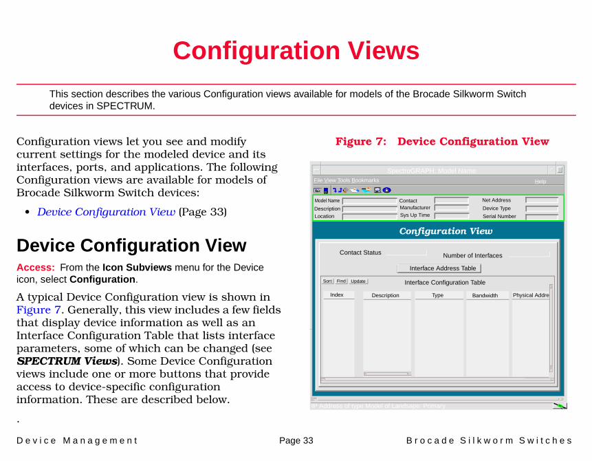
Configuration views let you see and modify current settings for the modeled device and its interfaces, ports, and applications. The following Configuration views are available for models of Brocade Silkworm Switch devices:
• Device Configuration View (Page 33)
Device Configuration ViewAccess: From the Icon Subviews menu for the Device icon, select Configuration.
A typical Device Configuration view is shown in Figure 7. Generally, this view includes a few fields that display device information as well as an Interface Configuration Table that lists interface parameters, some of which can be changed (see SPECTRUM Views). Some Device Configuration views include one or more buttons that provide access to device-specific configuration information. These are described below.
.
Figure 7: Device Configuration View
SpectroGRAPH: Model Name
Model Name
File View Tools Bookmarks Help
DescriptionLocation
ContactManufacturerSys Up Time
Net Address
Device Type
Serial Number
Configuration View
Contact Status Number of Interfaces
Interface Address Table
Sort Interface Configuration Table
Index Description Type Bandwidth Physical Addre
IP Address of type Model of Landsape: Primary
Find Update

C o n f i g u r a t i o n V i e w s D e v i c e C o n f i g u r a t i o n V i e w
D e v i c e M a n a g e m e n t Page 34 B r o c a d e S i l k w o r m S w i t c h e s
Refer to the SPECTRUM Views documentation.
IF Address Translation
D e v i c e M a n a g e m e n t Page 35 B r o c a d e S i l k w o r m S w i t c h e s
Model Information View
This section provides a brief overview of the Model Information view.
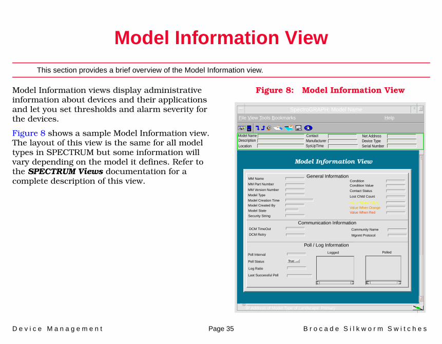
Model Information views display administrative information about devices and their applications and let you set thresholds and alarm severity for the devices.
Figure 8 shows a sample Model Information view. The layout of this view is the same for all model types in SPECTRUM but some information will vary depending on the model it defines. Refer to the SPECTRUM Views documentation for a complete description of this view.
Figure 8: Model Information View
Model Name ContactDescriptionLocation
SpectroGRAPH: Model Name
File View Tools Bookmarks Help
IP Address of Model Type of Landscape: Primary
ManufacturerSysUpTime
Net AddressDevice TypeSerial Number
Model Information View
MM Name
MM Part Number
MM Version Number
Model Type
Model Creation Time
Model Created By
Model State
Security String
Communication Information
Poll / Log Information
Condition Value
Contact Status
DCM TimeOut
DCM Retry
Lost Child Count
Value When Yellow
Value When OrangeValue When Red
Community Name
Mgnmt Protocol
Poll Interval
Poll Status
Log Ratio
Last Successful Poll
Logged Polled
True
General InformationCondition

D e v i c e M a n a g e m e n t Page 36 B r o c a d e S i l k w o r m S w i t c h e s
Traps, Events, and Alarms
This section provides you with an overview of trap, event, and alarm support.
This section describes any device-specific events and alarms supported by the Brocade Silkworm Switches (SM-BRC1000) management module.
• Standard Trap Support• Device-Specific Trap Support
Standard Trap SupportThe following standard traps are supported.
Device-Specific Trap SupportThe supported device-specific traps are listed in Table 10 (Page 37).
Table 9: Standard Trap Support
Standard Trap Name OID
coldStart 0.0
warmStart 1.0
linkDown 2.0
linkUp 3.0
authenticationFailure 4.0
egpNeighborLoss 5.0

T r a p s , E v e n t s , a n d A l a r m s D e v i c e - S p e c i f i c T r a p S u p p o r t
D e v i c e M a n a g e m e n t Page 37 B r o c a d e S i l k w o r m S w i t c h e s
Table 10: BROCADE-SW-TRAP-MIB Traps
Trap Name OID Variable BindingsEvent
GeneratedAlarm
GeneratedAlarm
Severity
swFault (Page 38) 1.3.6.1.4.1.1588.2.1.1.16.1 1.3.6.1.4.1.1588.2.1.1.1.1.20 0x043b0001 0x043b0001 Red
swSensorScn (Page 38)
1.3.6.1.4.1.1588.2.1.1.16.2 1.3.6.1.4.1.1588.2.1.1.1.1.22.1.11.3.6.1.4.1.1588.2.1.1.1.1.22.1.21.3.6.1.4.1.1588.2.1.1.1.1.22.1.3 1.3.6.1.4.1.1588.2.1.1.1.1.22.1.4 1.3.6.1.4.1.1588.2.1.1.1.1.22.1.5
0x043b0002 0x043b0002 Yellow
swScPortScn (Page 38)
1.3.6.1.4.1.1588.2.1.1.16.3 1.3.6.1.4.1.1588.2.1.1.1.6.2.1.11.3.6.1.4.1.1588.2.1.1.1.6.2.1.4
0x043b0003 0x043b0003 Yellow
swEventTrap (Page 38)
1.3.6.1.4.1.1588.2.1.1.16.4 1.3.6.1.4.1.1588.2.1.1.1.8.5.1.11.3.6.1.4.1.1588.2.1.1.1.8.5.1.21.3.6.1.4.1.1588.2.1.1.1.8.5.1.31.3.6.1.4.1.1588.2.1.1.1.8.5.1.41.3.6.1.4.1.1588.2.1.1.1.8.5.1.5
0x043b0004 0x043b0004 Yellow
swFabricWatchTrap (Page 38)
1.3.6.1.4.1.1588.2.1.1.16.5 1.3.6.1.4.1.1588.2.1.1.1.10.2.1.11.3.6.1.4.1.1588.2.1.1.1.10.3.1.11.3.6.1.4.1.1588.2.1.1.1.10.3.1.31.3.6.1.4.1.1588.2.1.1.1.10.3.1.61.3.6.1.4.1.1588.2.1.1.1.10.3.1.71.3.6.1.4.1.1588.2.1.1.1.10.3.1.81.3.6.1.4.1.1588.2.1.1.1.10.3.1.9
0x043b0005 0x043b0005 Yellow
swTrackChangesTrap (Page 38)
1.3.6.1.4.1.1588.2.1.1.16.6 1.3.6.1.4.1.1588.2.1.1.1.1.23 0x043b0006 0x043b0006 Yellow

T r a p s , E v e n t s , a n d A l a r m s D e v i c e - S p e c i f i c T r a p S u p p o r t
D e v i c e M a n a g e m e n t Page 38 B r o c a d e S i l k w o r m S w i t c h e s
Proprietary Trap DescriptionsswFaultA swFault(1) is generated whenever the diagnostics detect a fault with the switch.
swSensorScnA swSensorScn(2) is generated whenever an environment sensor changes its operational state, for example a fan stops working. The VarBind in the Trap Data Unit shall contain the corresponding instance of the sensor status, sensor index, sensor type, sensor value (reading) and sensor information. Note that the sensor information contains the type of sensor and its number in textual format.
swScPortScnA swFCPortScn(3) is generated whenever an FC_Port changes its operational state. For example, the FC_Port goes from on-line to offline. The VarBind in the Trap Data Unit shall contain the corresponding instance of the FC_Port's operational status and index.
swEventTrapThis trap is generated when an event with a level at or below swEventTrapLevel occurs.
swFabricWatchTrapThis is the trap to be sent by Fabric Watch to indicate that an event has occurred.
swTrackChangesTrapThis is the trap to be sent for tracking login/logout/config changes.

D e v i c e M a n a g e m e n t Page 39 B r o c a d e S i l k w o r m S w i t c h e s
Index
AAddress
Interface IP 10Physical (MAC) 10Translation 11
Admin Status 9Agent Trap Recipient 18Alarm Generated 37Alpa 25Alpa CRC Count 26Applications 29
BBaud Rate 18Beacon 16Behavior Int 23Behavior Type 23Boot Prom 15
CConfiguration
Device 33COS 22
Cust Timebase 24
DDevTop Views 12Documentation 4Domain ID 17
EEvent Generated 37
FFC-4s 23Filter Alias 27Filter Count 27Firmware 15FLASH 15
HHard Address 23Hardware 5
IIcons
Device 5Interface 9
InterfaceType, Device 9
IP Address 22IPA 22
LLips Ins 21Lips Last Alpa 21Lips Outs 21
MManagement Tasks 7Mask 11Model
Information 35Types of 5

I n d e x I n d e x
D e v i c e M a n a g e m e n t Page 40 B r o c a d e S i l k w o r m S w i t c h e s
NNeighbor Table 17Network I/O ports 12Network Type 10Node Symbol 22
OOID 37
PPassword 16Performance Statistics 32Port Capacity 18Port Number, Device 9Port Symbol 22Port Table 18Port Trunked 28POST Result 16Principal Switch 17
RRemote Domain 18RX C2 20RX C2 Frames 20RX C3 20
RX LCs 20RX Words 20
SSensor Table 17Serial ports 12Statistics
Routing Frame Transmission 32
TTelnet Admin Status 14Threshold Information 10Track Changes String 14Trap Name 37Trap Support 36Troubleshooting 7Trunk Group Number 28Trunk Group Rx 28Trunk Master 28Trunk Port 28TX Frames 20TX Type 20TX Words 20
VValid Acts 25
WWorld Wide Name 21Write Thresh Vals 24