broadcast transmission dynamic audio processing
DESCRIPTION
RadioTRANSCRIPT

TRANSMISSION AUDIO PROCESSING
by Robert Orban, Chief Engineer
Orban
1 Introduction Transmission audio processing is both an engineering and artistic discipline. The engineering goal is to make most efficient use of the signal-to-noise ratio and audio bandwidth available from the transmission channel while preventing its overmodulation. The organization using audio processing sets the artistic goal. It may be to avoid audibly modifying the original program material at all. Alternatively, it may be to create a distinct “sonic signature” for the broadcast by radically changing the sound of the original. Most broadcasters operate some-where in between these two extremes.
If the transmitted signal meets regulatory requirements for modulation control and RF bandwidth, there is no well defined “right” or “wrong” way to process audio. Like most areas requiring subjective, artistic judgment, processing is highly controversial and likely to provoke thoroughly opinionated arguments amongst its practitioners. Ultimately, the success of a broadcast's audio processing must be judged by its results — if the broadcast gets the desired audience, then the processing must be deemed satisfactory regardless of the opinions of audiophiles, purists, or others who consider processing an unnecessary evil.
One mark of the professionalism of a broadcast engineer is his or her mastery of the techniques of audio processing. The canny practitioner has a bag of tricks that can be used to achieve the processing goal specified by the station's management, whether it is “purist” or “squashed against the wall.”
2 Fundamentals of Audio Processing Compression
Compression reduces dynamic range of program material by reducing the gain of material whose average or rms level exceeds the threshold of compression. The amount by which the gain is reduced is called the gain reduction (abbreviated G/R).

Robert Orban: TRANSMISSION AUDIO PROCESSING Page 2
Above threshold, the slope of the input vs. output curve is the compression ratio. Low ratios provide “loose” control over levels, but generally sound more natural than high ratios, which provide “tight” control.
The knee of the input/output level graph can show an abrupt transition into compression (hard-knee), or a gradual transition, in which the ratio becomes progressively larger as the amount of gain reduction increases (soft-knee).
The attack time is, generally, the time that it takes the compressor to settle to a new gain following a step increase in level. There is no generally agreed upon way to measure attack time. Some measure it as the “time constant” — the time necessary for the gain to achieve 67% of its new value. Others measure it as the time for the gain to reach 90% of its new value for a given amplitude step (often 10dB).
The release time is the time necessary for the gain to recover to within a certain percent of its final value after the level of the input signal to the compressor has declined below the compression threshold. It is sometimes convenient to specify the release time in dB per second if the shape of the release time is a straight line on a dB vs. time graph. However, this shape often is not linear. Multiple time constant (sometimes called “automatic”) release time circuits change the release rate (in dB/second) according to the history of the program, and according to how much gain reduction is in use. For example, the release time will temporarily speed up after an abrupt transient, to prevent a “hole” from being punched in the program by the gain reduction. The release time may slow down as 0dB gain reduction is approached to make compression of wide dynamic range program material less obvious to the ear.
Delayed Release holds the gain constant for a short time (typically less than 20 milliseconds) after gain reduction has occurred. This prevents fast release times from causing modulation of individual cycles in the program waveform, thus reducing the tendency of the compressor to introduce harmonic or intermodulation distortion when operated with fast attack and release.
Figure 1: Input vs. Output Levels for Compressors

Robert Orban: TRANSMISSION AUDIO PROCESSING Page 3
Expansion
Expansion increases the dynamic range of program material by reducing gain when the pro-gram level is lower than the threshold of expansion. The primary purpose of expansion is to reduce noise, either electronic or acoustic. Expanders are often coupled to compressors so that low-level program material is not amplified, thus reducing the noise that would otherwise be exaggerated by the compression. Expanders have attack times, release times, and expansion ratios that are analogous to those for compressors.
Peak Limiting and Clipping
Peak limiting is an extreme form of compression characterized by a very high compression ratio, fast attack time (typically less than 2 milliseconds), and fast release time (typically less than 200 milliseconds). In modern audio processing, a peak limiter, by itself, usually limits the peaks of the envelope of the waveform, as opposed to individual instantaneous peaks in the waveform. Clipping usually controls these. As a matter of good engineering practice, peak limiters are usually adjusted to produce no more than 6dB of gain reduction to prevent offensive audible side effects.
The main purpose of limiting is to protect a subsequent channel from overload, as opposed to compression, whose main purpose is to reduce dynamic range of the program.
Peak clipping is a process that instantaneously chops off any part of the waveform that exceeds the threshold of clipping. This threshold can be either symmetrical or asymmetrical around zero volts. While peak clipping can be very effective, it causes audible distortion when over-used. It also increases the bandwidth of the signal by introducing both harmonic and intermodulation distortion into its output signal. Manufacturers of modern audio processors have therefore developed various forms of overshoot compensation, which is essentially peak clipping that does not introduce significant out-of-band spectral energy into its output.
Figure 2: Input vs. Output Levels for Expanders

Robert Orban: TRANSMISSION AUDIO PROCESSING Page 4
Radio-Frequency clipping (“RF clipping”) is peak clipping applied to a single-sideband RF signal. (A typical carrier frequency is 1MHz). All clipping-induced harmonics fall around harmonics of the carrier (2MHz…). Upon demodulation, these harmonics remain at high frequencies and are removed by a low-pass filter. Thus, RF clipping produces only inter-modulation distortion, and no harmonic distortion. Ordinary (“AF” or audio frequency) clipping produces both. RF clipping is substantially more effective than AF clipping on voice because intermodulation distortion is less objectionable than harmonic distortion in this application. On the other hand, RF clipping is much more objectionable than AF clipping on music.
The Hilbert-Transform clipper1 combines the features of RF and AF clippers. It acts as an RF clipper below 4kHz (the region in which most voice energy is located), and acts as an AF clipper above 4kHz to prevent excessive intermodulation distortion with music.
Unless a limiter has an attack time of less than about 10µs, it will exhibit overshoots at its output. If the goal of the processing is to precisely constrain the instantaneous values of the waveform to a given threshold, it usually sounds best to control these overshoot by a limiter with 2ms attack time followed by a clipper. Attempting to provide all peak control with the limiter does not sound as good, because the clipper affects only the offending overshoot and does not apply gain reduction to the surrounding signal.
When used in this way, clippers can cause audible distortion on certain program material. However, fast-attack limiters will cause audible clipping of the first half-cycle of certain pro-gram, like solo piano, harp, nylon-string acoustic guitar, etc. A delay-line limiter2 can eliminate such distortion. This device consists of two audio paths. The audio is applied to a pilot limiter, which has a very fast attack time. The gain-control signal generated by the pilot limiter is applied to a low-pass filter to smooth its sharp edges, and then to the gain control port of the variable-gain amplifier that passes the actual program signal. To compensate for the group delay in the control-voltage low-pass filter (which delays application of gain control to the audio), the audio is delayed equally by a delay line prior to the variable-gain amplifier's input.
Gating
There are two fundamental types of gates, the noise gate and the compressor gate. The com-pressor gate prevents any change in background noise during pauses or low-level program material by “freezing” the compressor gain when the input level drops below the threshold of gating. Because it produces natural sound, it is very popular in broadcasting.
1 R. Orban: “Increasing Coverage of International Shortwave Broadcast Through Improved Audio Processing Techniques,” J. AES, Vol. 38, Number 6 pp. 419 (June 1990)
2 British Broadcasting Corporation Engineering Division: “The dynamic characteristics of limiters for sound programme circuits,” Research Report No. EL-5, 1967.
Robert Orban: TRANSMISSION AUDIO PROCESSING Page 5
Many compressor gates will, instead of freezing the gain, cause it to move very slowly to a nominal value (typically 10dB of gain reduction) if the gating period is long enough. This prevents the compressor from being stuck with an unusually high or low gain.
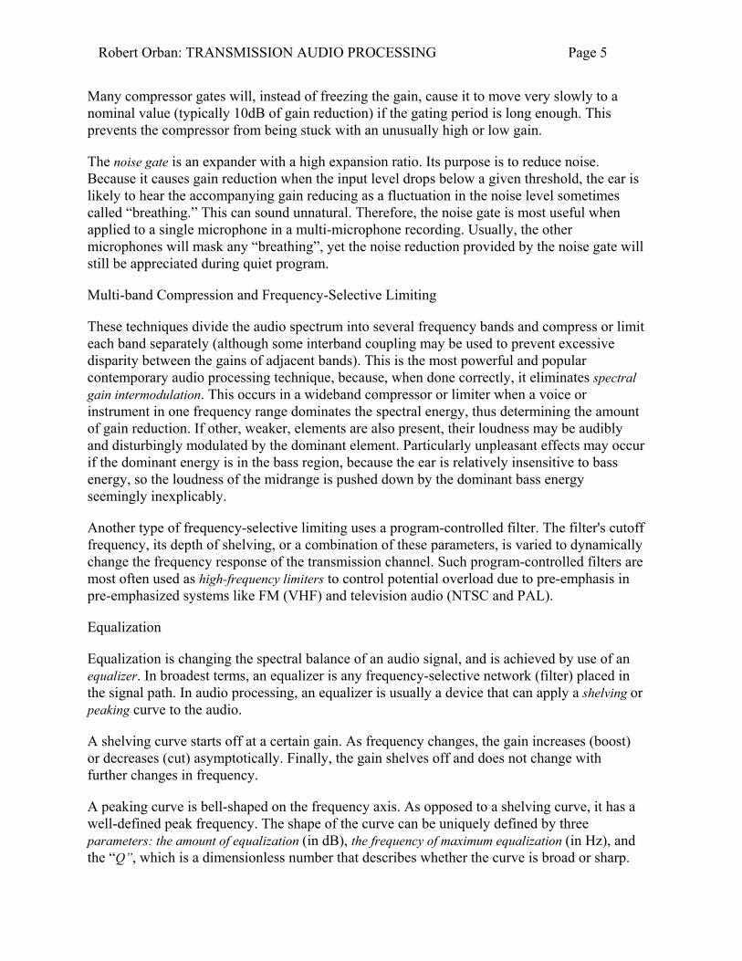
The noise gate is an expander with a high expansion ratio. Its purpose is to reduce noise. Because it causes gain reduction when the input level drops below a given threshold, the ear is likely to hear the accompanying gain reducing as a fluctuation in the noise level sometimes called “breathing.” This can sound unnatural. Therefore, the noise gate is most useful when applied to a single microphone in a multi-microphone recording. Usually, the other microphones will mask any “breathing”, yet the noise reduction provided by the noise gate will still be appreciated during quiet program.
Multi-band Compression and Frequency-Selective Limiting
These techniques divide the audio spectrum into several frequency bands and compress or limit each band separately (although some interband coupling may be used to prevent excessive disparity between the gains of adjacent bands). This is the most powerful and popular contemporary audio processing technique, because, when done correctly, it eliminates spectral gain intermodulation. This occurs in a wideband compressor or limiter when a voice or instrument in one frequency range dominates the spectral energy, thus determining the amount of gain reduction. If other, weaker, elements are also present, their loudness may be audibly and disturbingly modulated by the dominant element. Particularly unpleasant effects may occur if the dominant energy is in the bass region, because the ear is relatively insensitive to bass energy, so the loudness of the midrange is pushed down by the dominant bass energy seemingly inexplicably.
Another type of frequency-selective limiting uses a program-controlled filter. The filter's cutoff frequency, its depth of shelving, or a combination of these parameters, is varied to dynamically change the frequency response of the transmission channel. Such program-controlled filters are most often used as high-frequency limiters to control potential overload due to pre-emphasis in pre-emphasized systems like FM (VHF) and television audio (NTSC and PAL).
Equalization
Equalization is changing the spectral balance of an audio signal, and is achieved by use of an equalizer. In broadest terms, an equalizer is any frequency-selective network (filter) placed in the signal path. In audio processing, an equalizer is usually a device that can apply a shelving or peaking curve to the audio.
A shelving curve starts off at a certain gain. As frequency changes, the gain increases (boost) or decreases (cut) asymptotically. Finally, the gain shelves off and does not change with further changes in frequency.
A peaking curve is bell-shaped on the frequency axis. As opposed to a shelving curve, it has a well-defined peak frequency. The shape of the curve can be uniquely defined by three parameters: the amount of equalization (in dB), the frequency of maximum equalization (in Hz), and the “Q”, which is a dimensionless number that describes whether the curve is broad or sharp.

Robert Orban: TRANSMISSION AUDIO PROCESSING Page 6
A parametric equalizer provides several peaking equalizers, in which the user has control of all three parameters. This type of equalizer is generally considered to be the most flexible and musical-sounding equalizer. Some parametric equalizers can also be used as notch filters.
A graphic equalizer provides a number of peaking equalizers (usually 8 to 31) distributed on spaced frequency centers throughout the audible range. The controls for the amount of equalization are linear-throw faders, and are arranged on the panel in order of frequency. The positions of the controls, when considered together, thus provide a very rough “graphic” display of the amount of equalization provided by the entire equalizer. The advantage of a graphic equalizer is that it is easy to understand and quick to adjust. Its primary disadvantage is lack of flexibility: Usually, only the amount of equalization is adjustable, the “Q” and center frequency being fixed. However, a few manufacturers make parametric equalizers with graphic-style controls. These provide the advantages of both types.
Low-pass and high-pass filters remove spectrum at the top and bottom of the audible range, respectively. They are usually used to remove unwanted high- or low-frequency noise, and can also produce special effects (like telephone simulation).
These filters come with their rate of cutoff fixed in multiples of 6dB/octave. 12dB/octave and 18dB/octave are popular. In addition, the shape of the region around the cutoff frequency has considerable effect on the listening quality of such filters. Bessel (constant-delay) filters have a gentle transition into cutoff, and sound pleasant and musically neutral. Butterworth (maximally-flat magnitude) filters have a sharper transition into cutoff. They are more effective at removing noise than Bessel filters, but have a more colored listening quality.
Equalizers are sometimes used on-line in transmission to create a certain sonic signature for a broadcast. Any of the types above may be used. Commercial audio processors may include equalizers for program coloration, or for correcting the frequency response of subsequent transmission links. Sometimes the various bands of a multi-band compressor or limiter are used as an equalizer by adjusting the gains of the various bands to achieve the desired equalized frequency response.
Loudness
One of the main uses of audio processing is to increase perceived loudness within the peak modulation constraints of a transmission channel. Assessing the effectiveness of audio pro-cessing thus requires a means of measuring loudness. Loudness is subjective: it is the intensity of sound as perceived by the ear/brain system. No simple meter, whether PPM or VU, provides a reading that correlates well to perceived loudness. A meter that purports to measure loudness must agree with a panel of human listeners.
Three important factors correlate to subjective loudness:
1. The spectral distribution of the sound energy (the ear's sensitivity vs. frequency — the ear is most sensitive from 2 to 8kHz. Sensitivity falls off fastest below 200Hz.)

Robert Orban: TRANSMISSION AUDIO PROCESSING Page 7
2. Whether the sound energy is concentrated in a wide or narrow bandwidth. (“Loudness Summation” — for a given total sound power, the sound becomes louder as the power is spread over a larger number of “critical bands” [about 1/3 octave].)
3. The duration of the sound. A given amount of sound power appears progressively louder until its duration exceeds about 200 milliseconds, at which point no further loudness increase will occur.
Torick and Jones have published a paper describing a meter for measuring the loudness of broadcast signals3. The FCC did an informal validation of the results of this meter, and concluded that it was effective in assessing whether commercials in television were noticeably louder than the surrounding entertainment programming.4
Additionally, the independently-developed loudness-measuring methods of Stevens and of Zwicker have both become international standards. Unfortunately, at the time of this writing there are no commercially-available loudness meters using the Jones & Torick, Stevens, or Zwicker methods. Practically, the relative loudness of various program segments must thus be judged subjectively. It is wise to use several auditors when doing this, and to ascertain that they all have normal hearing by conventional audiometric tests.
3 General Performance Requirements for Transmission Audio Processors Peak Modulation Control
The audio processor must control the peak modulation of the RF carrier to the standards required by the governing authority, such as the FCC in the United States. In AM, this usually means that negative carrier pinch-off must not occur at any time because this would cause splatter interference into adjacent channels. In FM and television (NTSC and PAL5), the peak deviation of the carrier must be controlled so that the modulation monitor specified by the governing authority does not indicate overmodulation. Because the rules often permit the modulation monitor to ignore very brief overshoots, the instantaneous peak deviation might exceed the peak modulation as indicated on the modulation monitor.
3 B.L. Jones and E.L. Torick: “A New Loudness Indicator for Use in Broadcasting,” J.SMPTE, Sept. 1981, p. 772
4 R.A. Haller, “An Update on the Technology of Loud Commercial Control,” OST Technical Memorandum FCC/OST TM83-1, February 1983.
5 SECAM customarily uses AM sound, with the usual requirements for preventing carrier pinch-off.

Robert Orban: TRANSMISSION AUDIO PROCESSING Page 8
The requirements for peak control and spectrum control tend to conflict, which is why so-phisticated non-linear filters are required to achieve highest performance. Applying a peak-controlled signal to a linear filter almost always causes the filter to overshoot and ring because of two mechanisms: spectrum truncation and time dispersion. One can build a square wave by summing its Fourier components together with correct amplitude and phase. Analysis shows that the fundamental of the square wave is approximately 2.1dB higher than the amplitude of the square wave itself. As each harmonic is added in turn to the fundamental, a given harmonic's phase is such that the peak amplitude of the resulting waveform decreases by the largest possible amount. Simultaneously, the R.M.S. value increases because of the addition of the power in each harmonic. This is the fundamental theoretical reason why simple clipping is such a powerful tool for improving the peak-to-average ratio of broadcast audio: clipping adds to the audio waveform spectral components whose phase and amplitude are precisely correct to minimize the waveform's peak level while simultaneously increasing the power in the waveform.
If a square wave (or clipped waveform) is applied to a low-pass filter with constant time delay at all frequencies, the higher harmonics that reduce the peak level will be removed, increasing the peak level and with it the peak-to-average ratio. Thus even a perfectly phase-linear6 low-pass filter will cause overshoot. There is no sharp-cutoff linear low-pass filter that is overshoot-free: overshoot-free spectral control to FCC or CCIR standards must be achieved with filters that are embedded within the processing, such that the non-linear peak-controlling elements in the processor can also control the overshoot.
If the sharp-cutoff filter is now allowed to be minimum-phase7, it will exhibit a sharp peak in group delay around its cutoff frequency. Because the filter is no longer phase-linear, it will not only remove the higher harmonics required to minimize peak levels, but will also change the time relationship between the lower harmonics and the fundamental. They become delayed by different amounts of time, causing the shape of the waveform to change. This time dispersion will therefore further increase the peak level.
When a square wave is applied to a linear-phase filter, overshoot and ringing will appear symmetrically on the leading and trailing edge of the waveform. If the filter is minimum-phase, the overshoot will appear on the leading edge and will be about twice as large. In the first case, the “overshoot and ringing” are in fact caused by spectrum truncation which eliminates harmonics necessary to minimize the peak level of the wave at all times; in the second case, the
6 A phase-linear filter has constant delay with frequency.
7 A minimum phase filter has no zeros in the right half of the s-plane. As its name implies, there is no filter with the same magnitude response that can have less phase shift. Given the magnitude response of a minimum-phase filter, its phase shift can be computed (with the Hilbert Transform). This means that if a minimum-phase filter has constant group delay in its passband, this is associated with a certain type of magnitude response which rolls off gently around the filter's cutoff frequency: a minimum phase filter with constant group delay in the passband cannot simultaneously have a highly selective magnitude response. Many textbooks provide the well-known mathematical details. See for example [H.J. Blinchikoff & A.I. Zverev: Filtering in the Time and Frequency Domains. New York, Wiley, 1976, pp. 89-94.]

Robert Orban: TRANSMISSION AUDIO PROCESSING Page 9
overshoot and ringing are caused by spectrum truncation and by distortion of the time relationship between the remaining Fourier components in the wave.
Other Considerations
Except as required to achieve very specific artistic goals (most notably in some major-market high-energy hit-music formats), the processed audio should be free from unnatural subjective side-effects, such as pumping (a sense that the gain is constantly and unnaturally changing — a characteristic side-effect of wideband compressors and limiters when driven heavily), breathing (audible pulling up of background noise, cured by a compressor gate), and hole-punching (a sudden drop in loudness after a program transient, caused by the transient's inducing a large amount of gain reduction which then does not decay quickly, and cured by multiple time-constant release time circuitry.)
The processor must be packaged so that it is easy to operate and maintain, and so that it can work in high RF fields without compromise.
The processor should have setup controls with enough versatility to enable the subjective effect to be readily tuned to the requirements of the broadcasting authority operating it. For mixed-format applications the processor may have several presets, selectable by remote control, that permit the operator to set the amount of compression, limiting, clipping, and other parameters to complement the program material being transmitted.
Ordinarily, the processor should be equipped with sufficient remote control facilities to enable it to be interfaced efficiently with modern, automated plants. Most of the required facilities are specific to the application: MW, HF (shortwave), FM (VHF), or television.
The processor should have sufficient metering to permit it to be easily set up with tones or program material. The metering should also provide diagnostic capabilities. Metering usually includes input level, output level, and “gain reduction” (the amount of limiting or compression) occurring in each variable-gain stage.
Processing for Stereo
Processing for stereophonic transmission is similar to processing for monophonic transmission, except that two audio processing chains are used. To preserve stereo imaging, the gains of the left and right automatic gain control and compression circuitry must be identical. Conversely, experience has shown that fast peak limiting and high-frequency limiting circuits sound best when operated independently (without stereo coupling) because the ear does not perceive channel-imbalance-induced spatial shifts with these fast time constants, yet the ear can perceive the loudness in one channel's being modulated unnaturally by a dominant element in the other channel when the channels are coupled.
The gain of the coupled elements is determined by the requirements of the transmission service. In FM, the channel requiring the greatest amount of limiting determines the gain of both channels. The processor operates by sensing the higher of the left and right channels and

Robert Orban: TRANSMISSION AUDIO PROCESSING Page 10
determining the gain of both channels such that the higher channel does not exceed a given level at the processor's output.
In AM, the gain of both channels is controlled by sensing and controlling the level of their sum (L+R) because the envelope modulation represents the sum of the channels.
4 System Considerations Subjective Audio Processing Concepts
Loudness is increased by reducing the peak-to-average ratio of the audio. If peaks are reduced, the average level can be increased within the permitted modulation limits. The effectiveness with which this can be accomplished without introducing objectionable side effects (like clipping distortion) is the single best measure of audio processing effectiveness.
Density is the extent to which the amplitudes of audio signal peaks are made uniform (at the expense of dynamic range). Programs with large amounts of short-term dynamic range have low density; highly compressed programs have high density.
Compression reduces the difference in level between the soft and loud sounds to make more efficient use of permitted peak level limits, resulting in a subjective increase in the loudness of soft sounds. It cannot make loud sounds seem louder. Compression reduces dynamic range relatively slowly in a manner similar to “riding the gain”; limiting and clipping, on the other hand, reduce the short-term peak-to-average ratio of the audio.
Limiting increases audio density. Increasing density can make loud sounds seem louder, but can also result in an unattractive, busier, and flatter denser sound. It is important to be aware of the many negative subjective side effects of excessive density when setting controls which affect the density of the processed sound.
Clipping sharp peaks does not produce any audible side effects when done moderately. Ex-cessive clipping will be perceived as audible distortion.
Building a System
Combining several audio processors into a good-sounding system is tricky because of headroom and time-constant considerations. You must ensure that the device driving a given processor can drive that processor into full compression or limiting. If the driving device runs out of headroom before full limiting occurs in the driven device, then you cannot use that device to its full capability.
When cascading several processors, beware of interactions between their attack times and release times. It is wise to start the system with the slowest device. This is usually a com-pressor or automatic gain controller with slow attack and release times, and with a compressor gate to prevent noise breathing. Such a processor does not significantly increase the density of

Robert Orban: TRANSMISSION AUDIO PROCESSING Page 11
the audio; it simply does gentle gain-riding to ensure that following stages are driven at the correct level.
The slow AGC is often followed by a multi-band compressor with moderate attack and release time. Correctly-designed multi-band processors have these time constants optimized for each frequency band; the low-frequency bands have slower time constants than the high-frequency bands. This multi-band compressor usually does most the work in increasing program density.
The amount of gain reduction determines how much the loudness of soft passages will be increased (and, therefore, how consistent overall loudness will be). Our hypothetical system reduces gain with the broadband AGC and the multi-band compressor. The broadband AGC is designed to control average levels, and to compensate for a reasonable amount of operator error. It is not designed to substantially increase the short-term program density (the multi-band compressor and peak limiters do that).
Modern audio processing systems usually add other elements to the basic system described above. For example, it is not unusual to incorporate an equalizer to color the audio for artistic effect. The equalizer may be any of the types described on page 0, and is usually found between the slow AGC and the multi-band compressor. The multi-band compressor itself can also be used as an equalizer by adjusting the gains of its various bands.
Various low-pass filters are often included in the system to limit the bandwidth of the output signal to 15kHz (for FM), 10kHz (AM in NRSC countries), 4.5kHz (AM in EBU countries, and shortwave worldwide), or other bandwidths as required by the local regulatory authority. The final low-pass filter in the system is almost always overshoot-compensated to prevent introducing spurious modulation peaks into the output waveform.
High-pass filters may be incorporated to protect the transmitter. This is particularly important in high-power AM and shortwave installations exceeding 100kW carrier power.
A transmitter equalizer that corrects the pulse response of the transmitter is found on high-end AM processors.
Location of System Components
The best location for the processing system is as close as possible to the transmitter, so that the processing system's output can be connected to the transmitter through a circuit path that introduces the least possible change in the shape of the carefully peak-limited waveform at the processing system's output. Sometimes, it is impractical to locate the processing system at the transmitter, and it must instead be located on the studio side of the link connecting the audio plant to the transmitter. (The studio/transmitter link [“STL”] might be telephone or post lines, analog microwave radio, or various types of digital paths.) This situation is not ideal because artifacts that cannot be controlled by the audio processor can be introduced in the link to the transmitter or by additional peak limiters placed at the transmitter. (Such additional peak limiters are common in countries where the transmitter is operated by a different authority than that providing the broadcast program.)
Robert Orban: TRANSMISSION AUDIO PROCESSING Page 12
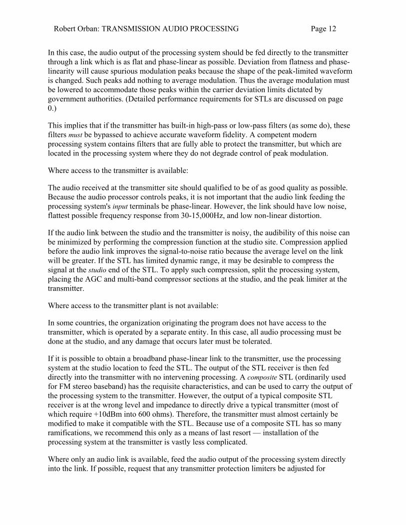
In this case, the audio output of the processing system should be fed directly to the transmitter through a link which is as flat and phase-linear as possible. Deviation from flatness and phase-linearity will cause spurious modulation peaks because the shape of the peak-limited waveform is changed. Such peaks add nothing to average modulation. Thus the average modulation must be lowered to accommodate those peaks within the carrier deviation limits dictated by government authorities. (Detailed performance requirements for STLs are discussed on page 0.)
This implies that if the transmitter has built-in high-pass or low-pass filters (as some do), these filters must be bypassed to achieve accurate waveform fidelity. A competent modern processing system contains filters that are fully able to protect the transmitter, but which are located in the processing system where they do not degrade control of peak modulation.
Where access to the transmitter is available:
The audio received at the transmitter site should qualified to be of as good quality as possible. Because the audio processor controls peaks, it is not important that the audio link feeding the processing system's input terminals be phase-linear. However, the link should have low noise, flattest possible frequency response from 30-15,000Hz, and low non-linear distortion.
If the audio link between the studio and the transmitter is noisy, the audibility of this noise can be minimized by performing the compression function at the studio site. Compression applied before the audio link improves the signal-to-noise ratio because the average level on the link will be greater. If the STL has limited dynamic range, it may be desirable to compress the signal at the studio end of the STL. To apply such compression, split the processing system, placing the AGC and multi-band compressor sections at the studio, and the peak limiter at the transmitter.
Where access to the transmitter plant is not available:
In some countries, the organization originating the program does not have access to the transmitter, which is operated by a separate entity. In this case, all audio processing must be done at the studio, and any damage that occurs later must be tolerated.
If it is possible to obtain a broadband phase-linear link to the transmitter, use the processing system at the studio location to feed the STL. The output of the STL receiver is then fed directly into the transmitter with no intervening processing. A composite STL (ordinarily used for FM stereo baseband) has the requisite characteristics, and can be used to carry the output of the processing system to the transmitter. However, the output of a typical composite STL receiver is at the wrong level and impedance to directly drive a typical transmitter (most of which require +10dBm into 600 ohms). Therefore, the transmitter must almost certainly be modified to make it compatible with the STL. Because use of a composite STL has so many ramifications, we recommend this only as a means of last resort — installation of the processing system at the transmitter is vastly less complicated.
Where only an audio link is available, feed the audio output of the processing system directly into the link. If possible, request that any transmitter protection limiters be adjusted for
Robert Orban: TRANSMISSION AUDIO PROCESSING Page 13
minimum possible action — the processing system does most of that work. Transmitter protection limiters should respond only to signals caused by faults or by spurious peaks in-troduced by imperfections in the link.
Where maximum quality is desired, it is wise to request that all equipment in the signal path after the studio be carefully aligned and qualified to meet the appropriate standards for bandwidth, distortion, group delay and gain stability, and that such equipment is re-qualified at reasonable intervals.
Requirements for Studio-Transmitter Links (“STLs”)
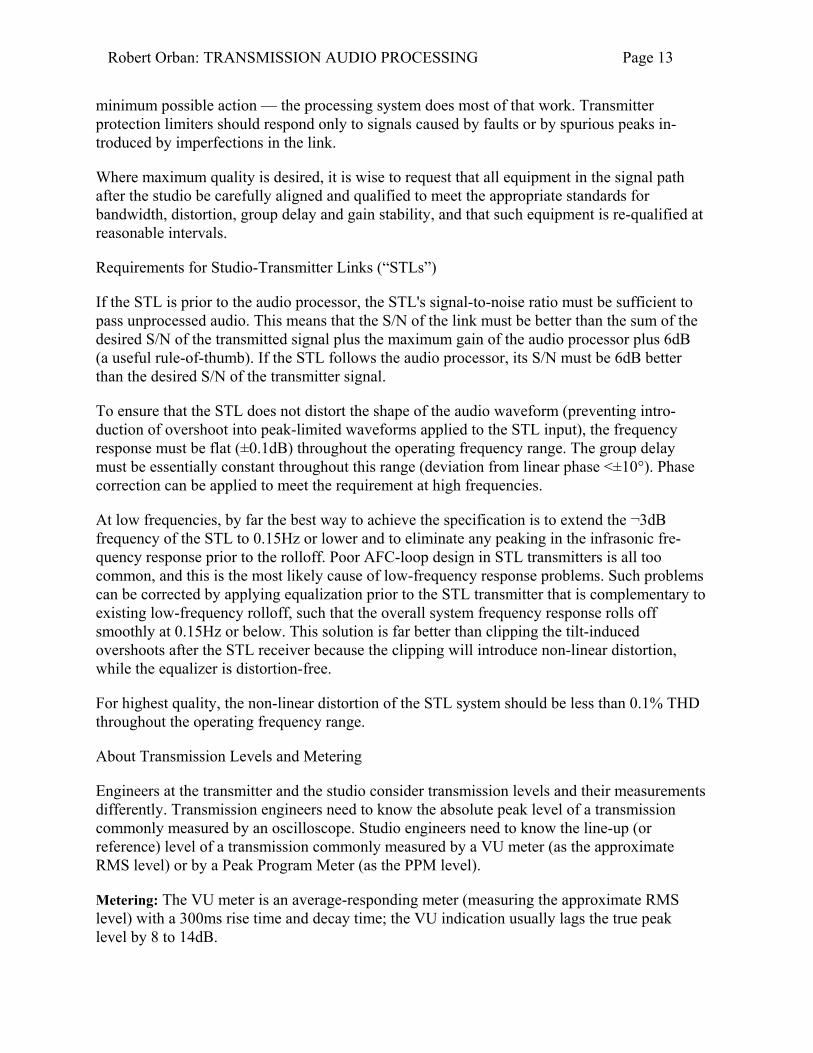
If the STL is prior to the audio processor, the STL's signal-to-noise ratio must be sufficient to pass unprocessed audio. This means that the S/N of the link must be better than the sum of the desired S/N of the transmitted signal plus the maximum gain of the audio processor plus 6dB (a useful rule-of-thumb). If the STL follows the audio processor, its S/N must be 6dB better than the desired S/N of the transmitter signal.
To ensure that the STL does not distort the shape of the audio waveform (preventing intro-duction of overshoot into peak-limited waveforms applied to the STL input), the frequency response must be flat (±0.1dB) throughout the operating frequency range. The group delay must be essentially constant throughout this range (deviation from linear phase <±10°). Phase correction can be applied to meet the requirement at high frequencies.
At low frequencies, by far the best way to achieve the specification is to extend the ¬3dB frequency of the STL to 0.15Hz or lower and to eliminate any peaking in the infrasonic fre-quency response prior to the rolloff. Poor AFC-loop design in STL transmitters is all too common, and this is the most likely cause of low-frequency response problems. Such problems can be corrected by applying equalization prior to the STL transmitter that is complementary to existing low-frequency rolloff, such that the overall system frequency response rolls off smoothly at 0.15Hz or below. This solution is far better than clipping the tilt-induced overshoots after the STL receiver because the clipping will introduce non-linear distortion, while the equalizer is distortion-free.
For highest quality, the non-linear distortion of the STL system should be less than 0.1% THD throughout the operating frequency range.
About Transmission Levels and Metering
Engineers at the transmitter and the studio consider transmission levels and their measurements differently. Transmission engineers need to know the absolute peak level of a transmission commonly measured by an oscilloscope. Studio engineers need to know the line-up (or reference) level of a transmission commonly measured by a VU meter (as the approximate RMS level) or by a Peak Program Meter (as the PPM level).
Metering: The VU meter is an average-responding meter (measuring the approximate RMS level) with a 300ms rise time and decay time; the VU indication usually lags the true peak level by 8 to 14dB.

Robert Orban: TRANSMISSION AUDIO PROCESSING Page 14
PPM indicates a level between RMS and the actual peak. The PPM reading has an attack time of 10ms, slow enough to cause the meter to ignore narrow peaks and lag the true peak level by 5dB or more.
Transmission Levels: The transmission engineer is primarily concerned with the peak overload level of a transmission to prevent overloading. This peak overload level is defined differently, system to system. In tape, it is defined as the level producing the amount of harmonic distortion considered “tolerable” — often 3% THD at 400Hz. In FM, microwave, or satellite links, it is the maximum-permitted RF carrier deviation. In AM, it is negative carrier pinch-off. In analog telephone transmission, it is the level above which serious crosstalk into other channels occurs, or the level at which the amplifiers in the channel overload. In digital, it is the largest possible digital word.
Studio Levels: The studio engineer is primarily concerned with what is commonly called the reference level, operating level or line-up level. This line-up level aids studio engineers in providing adequate headroom between line-up level and the overload level of equipment to allow for the peaks that the meter doesn't indicate. In facilities that use VU meters, line-up level is usually at 0VU, which corresponds to the studio standard level, typically +4 or +8dBu. In systems that use PPM, line-up level may be at PPM 4 (for the BBC standard) or at the studio standard level (often +6dBu).
Transmission-Link Limiting
Transmission-link limiting devices are sometimes used ahead of the transmission link to pro-tect it from overload. (These links might STLs, satellite uplinks, inter-studio digital links, and the like.) These devices are usually used below-threshold (that is, with no gain reduction) as protection limiters to control peak levels. They only produce gain reduction when abnormally high levels are applied to their input due to operator error or unforeseen level variations at the source. This is useful to transmission engineers concerned with overload, and as useful to studio engineers concerned with headroom. For the needs of both engineers, such a limiter's output must be adjusted to be at or slightly below the peak overload level of the transmission channel.
To properly match the studio line-up level to the transmission protection limiter, you must know the desired headroom. For example, assume that the transmission protection limiter produces 0dBu at its output at 100% modulation of the transmission link. Further assume that the line-up level in your organization is designed to allow 8dB of headroom. You would then adjust the input attenuator of the transmission protection limiter so that studio line-up tone produces ¬8dBu at the output of the transmission protection limiter.
This assumes that the amplifier or other link between the studio and the input of the transmission protection limiter has enough headroom to drive the transmission protection limiter into gain reduction without clipping this link. The transmission protection limiter only protects a link connected to its output. In the previous example, if the transmission protection limiter provides 15dB of maximum protection, the system prior to the transmission protection limiter requires 8 + 15 = 23dB of headroom above studio line-up level. If the link is simply an amplifier, this should be achievable without difficulty if the absolute level of the studio line-up
Robert Orban: TRANSMISSION AUDIO PROCESSING Page 15
tone is chosen carefully. In our example, if the amplifiers in the system clip at +21dBu, the absolute level of the studio line-up tone can be no greater than ¬2dBu (i.e., 23dB below +21dBu).
5 Audio Processing Requirements for MW and HF Broadcast Transmission In these amplitude-modulated services, reception is usually compromised by noise and interference and may be further compromised by acoustic noise in the listening environment (like the automobile). Thus the processor must fight this noise (electrical and acoustic) and interference by reducing dynamic range. This is most readily done by multi-band compression and limiting to achieve lowest peak-to-average ratio without processing-induced side-effects.
The processor must provide absolute negative peak control to prevent carrier pinch-off, which would otherwise cause out-of-band emissions. Additionally, the processor must incorporate overshoot-free filtering to control the audio input spectrum to the transmitter, thus preventing out-of-band emissions and interference. The permissible radiated spectrum is usually specified by national or international broadcast authorities (most notably the CCIR) so as to make most efficient use of available radio frequency spectrum.
The processor should optionally provide a receiver equalizer that compensates for the poor frequency response of the typical MW or SW radio due to narrowband RF and IF stages.
Transmitter Equalization
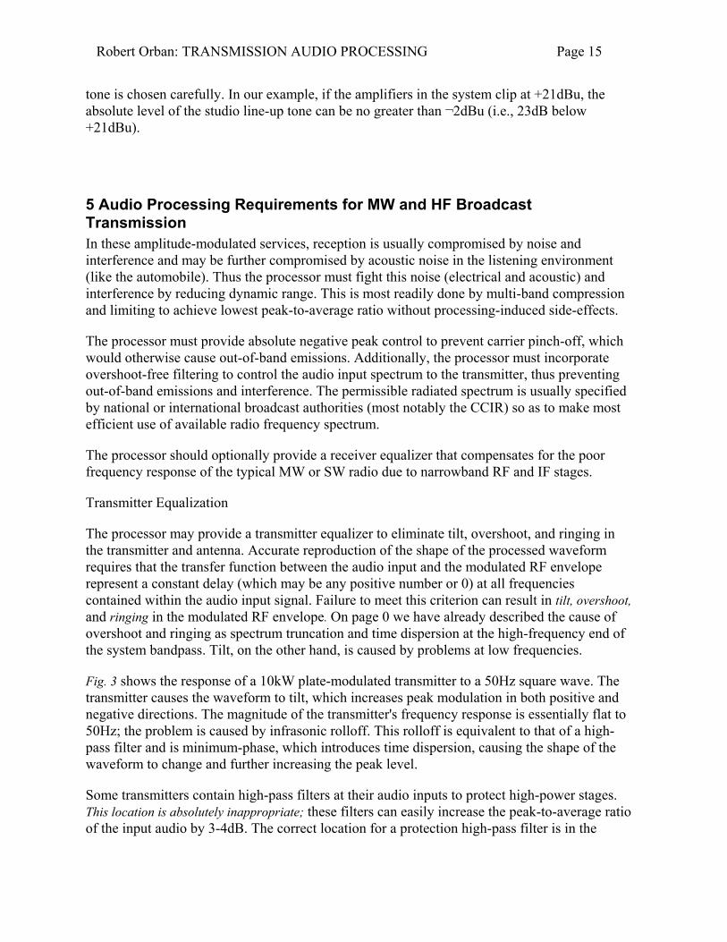
The processor may provide a transmitter equalizer to eliminate tilt, overshoot, and ringing in the transmitter and antenna. Accurate reproduction of the shape of the processed waveform requires that the transfer function between the audio input and the modulated RF envelope represent a constant delay (which may be any positive number or 0) at all frequencies contained within the audio input signal. Failure to meet this criterion can result in tilt, overshoot, and ringing in the modulated RF envelope. On page 0 we have already described the cause of overshoot and ringing as spectrum truncation and time dispersion at the high-frequency end of the system bandpass. Tilt, on the other hand, is caused by problems at low frequencies.
Fig. 3 shows the response of a 10kW plate-modulated transmitter to a 50Hz square wave. The transmitter causes the waveform to tilt, which increases peak modulation in both positive and negative directions. The magnitude of the transmitter's frequency response is essentially flat to 50Hz; the problem is caused by infrasonic rolloff. This rolloff is equivalent to that of a high-pass filter and is minimum-phase, which introduces time dispersion, causing the shape of the waveform to change and further increasing the peak level.
Some transmitters contain high-pass filters at their audio inputs to protect high-power stages. This location is absolutely inappropriate; these filters can easily increase the peak-to-average ratio of the input audio by 3-4dB. The correct location for a protection high-pass filter is in the

Robert Orban: TRANSMISSION AUDIO PROCESSING Page 16
Figure 3: Tilt in Plate-Modulated Transmitter
audio processor where measures can be taken to prevent the high-pass filter from increasing the peak-to-average ratio at the audio processor's output.
Bounce: Linear errors can be equalized by pre-distorting the waveform in the audio processor. However, there is one major non-linear error, commonly called “power supply bounce.” This is caused by resonances in the LC filter elements of the transmitter's high voltage power supply. These resonances superimpose a sub-audible modulation onto the power supply voltage, resulting in a sort of very fast carrier shift that is too quick to be seen on a conventional carrier shift meter. The net result is to compromise the control of modulation peaks, particularly on strong bass transients which cause momentarily large current demands on the power supply, and which excite the resonance.
In the poorest transmitters, bounce has been known to compromise achievable modulation by up to 3dB. Because bounce is not linearly related to the modulation, small-signal equalization cannot cure it. The most successful cure has been the use of a 12-phase power supply in the transmitter. The AC ripple from such a supply is down about 40dB without filtering; a simple filter capacitor is all that is necessary to achieve adequate smoothing. Because there are no chokes in the power supply filter, resonance cannot occur. In all cases, bounce can be minimized by preventing excessive bass energy from being applied to the transmitter.
Slew Rate Limiting (“Transient Intermodulation Distortion”): Transmitters using pulse-duration modulation schemes are prone to problems with slew rate limiting. Because the PDM low-pass filter is located within the audio feedback loop of the transmitter, and because this filter is typically a multi-pole elliptic function filter with a cutoff frequency below 70kHz, it will introduce very substantial delay into the feedback loop. This has two consequences: stability requires the amount of feedback applied around the transmitter to be limited, and it also requires that the open-loop gain of the modulator be rolled-off at a very low frequency. The first makes it difficult to design PDM transmitters with THD below 1%-2% at midrange

Robert Orban: TRANSMISSION AUDIO PROCESSING Page 17
frequencies, while the second renders “transient intermodulation distortion” (non-linear behavior of the amplification stage prior to the frequency compensation stage) probable8. To minimize the probability that TIM will be bothersome, any amplification stage before the frequency compensation stage should be designed to be very linear to its clipping point, and to have sufficiently high headroom to accommodate the maximum rate of change to be expected at the transmitter's audio input9.
A transmitter should be qualified for TIM by one of the various difference-frequency inter-modulation distortion tests; if such tests indicate that the transmitter has a low slew rate, such a transmitter will not respond well to pre-emphasized audio and pre-emphasis will have to be reduced until the first derivative of the processed audio waveform seldom, if ever, exceeds the slew rate limit of the transmitter. Because of the benefits of pre-emphasis at the receiver, it is desirable to modify such transmitters to increase their slew rate, even if this means somewhat compromising harmonic distortion performance at low frequencies.
The NRSC-1 Audio Standard
Over the years, as the North American MW band became more crowded, interference from first and second adjacent stations became more and more of a problem. Receiver manufacturers
8 An astonishing amount of ink was wasted in the learned and popular press over the basically trivial issue of +transient intermodulation distortion+. (An irreverent colleague of ours once defined it as +intermodulation distortion caused by vagrants+.) Simply stated, almost all feedback systems contain a filter that forces the open loop characteristic to be either low-pass (all-pole; +lag compensation+) or low-pass shelving, with poles and zeros (+lead-lag compensation+). Feedback forces the amplifier before this filter to present a pre-emphasized signal to the filter's input such that the total response of the system is flat. If the filter rolls off at 6dB/octave starting at 15Hz (a typical situation in an opamp like the TL072 or the LF353), this pre-emphasis rises at 6dB/octave starting at 15Hz. High frequencies applied to this system will obviously challenge the headroom of the amplifier prior to the filter _ in our example, 20kHz will be up 62.4dB! If high frequencies drive the amplifier prior to the filter into clipping or substantially non-linear operation, +transient intermodulation distortion+ occurs. Because the clipping process is followed by a filter with a low-pass characteristic, harmonics generated by clipping will be de-emphasized, so difference-frequency IM tests are more sensitive than THD tests to this mechanism. And that is all that needs to be said.
9 For a maximum audio bandwidth f, the required slew rate in percent modulation per microsecond is 0.0002pf %/µs. For 4.5kHz, this is 2.827%/µs.

Robert Orban: TRANSMISSION AUDIO PROCESSING Page 18
responded by producing receivers with decreased audio bandwidth, so that the encroachment of an adjacent station's modulation extremes would not be audible as interference.
This truncating of the bandwidth had the effect of diminishing the receiver's high-frequency response, but it was felt that lower fidelity would be less obnoxious than interference. To address these problems, the National Radio Systems Committee (NRSC) in 1987 formalized a standard for pre-emphasis and low-pass filtering for AM broadcast to provide brighter sound at the receiver while minimizing interference.
AM Stereo Introduces a Pre-emphasis Dilemma: Certain AM receivers manufactured since 1984 for sale in North America, particularly those designed for domestic AM stereo reception, have a frequency response that is substantially wider than that of the typical mono AM receiver. The frequency response was widened largely to enhance the sales potential of AM stereo by presenting a dramatic, audible improvement in fidelity in the showroom. As these new receivers became more prevalent, broadcasters had to choose whether the station's pre-emphasis would be optimized for the new AM stereo receivers or for the existing conventional receivers that form the vast majority of the market.
If the choice was for conventional receivers (which implies a relatively extreme pre-emphasis), the newer receivers might sound strident or exceptionally bright. If the choice favored the newer receivers (less pre-emphasis and probably less processing), the majority of receivers would be deprived of much high-end energy and would sound both quieter and duller.
NRSC Standard Pre-emphasis and Low-pass Filtering: In response to this dilemma, the NRSC undertook the difficult task of defining a voluntary recommended pre-emphasis curve for AM radio that would be acceptable to broadcasters (who want the highest quality sound on the majority of their listeners' radios) and to receiver manufacturers (who are primarily concerned with interference from first- and second-adjacent stations).
After a year of deliberation, a “modified 75-microsecond” pre-emphasis/de-emphasis standard was approved (see Fig. 4). This provides a moderate amount of improvement for existing narrowband radios, while optimizing the sound of wideband radios. Most importantly, it generates substantially less first-adjacent interference than do steeper pre-emphasis curves.
The second part of the NRSC standard calls for a sharp upper limit of 10kHz for the audio presented to the transmitter (see Fig. 5). This essentially eliminates interference to second and higher adjacencies. While some have protested that this is inadequate and that 15kHz audio should be permitted, the unfortunate fact is that interference-free 15kHz audio could only be achieved by a complete re-allocation of the AM band! The practical effect of widespread implementation of the 10kHz standard is that 10kHz radios will then be feasible, and the bandwidth perceived by the average consumer (now limited by the receiver to 3kHz, typically) will be dramatically improved. On much mass-market consumer equipment, it will be difficult to tell AM from FM.
On April 27, 1989, The FCC released a Report and Order that amended section 73.44 of the FCC Rules by requiring all U.S. AM stations to comply with the occupied bandwidth specifications of the NRSC-2 standard by June 30, 1990. The NRSC-2 standard is an “RF

Robert Orban: TRANSMISSION AUDIO PROCESSING Page 19
Figure 4: NRSC Pre-Emphasis Curve
mask” which was derived from the NRSC-1 audio standard by the NRSC. The purpose of the NRSC-2 RF mask is to provide a transmitted RF occupied bandwidth standard that any station with a properly-operating transmitter will meet, provided that NRSC-1 audio processing is used prior to the transmitter, and provided that the station is not over-modulating.
The Report and Order provides for “presumptive compliance” with the NRSC-2 occupied bandwidth standard: prior to June 30, 1994, any station whose audio complies with the NRSC-1 standard (an audio standard) is presumed to comply with the NRSC-2 standard (an RF occupied bandwidth standard) unless the station receives an Official Notice of Violation or a Notice of Apparent Liability from the Commission alleging non-compliance with the NRSC-2 occupied bandwidth standard.
The radio manufacturers participating in the NRSC stated emphatically that reduction in in-terference must be demonstrated by broadcasters before receiver manufacturers would be willing to release true wideband (10kHz audio bandwidth) receivers to the mass market. This is rational — the receiver manufacturers can lose millions of dollars if they produce receivers that are rejected as noisy or interference-prone by consumers. In contrast, broadcasters can easily change pre-emphasis and filtering with very little expense.
It would therefore be wise to strictly conform to the standard even if it were not required by the FCC. It is likely that use of this more modest pre-emphasis and sharp 10kHz filtering by broadcasters is the only factor that will eventually induce the receiver manufacturers to build and mass-market the high-fidelity, wideband radios that would allow AM stations to compete with FM in audio quality. The commitment to do so was strongly expressed by the receiver manufacturers involved in the NRSC's deliberations.

Robert Orban: TRANSMISSION AUDIO PROCESSING Page 20
Audio Processing for AM Stereo
In all AM stereo systems, the envelope modulation is forced to a close approximation of the sum of the left and right channels to ensure compatibility with mono radios equipped with envelope detectors. To ensure minimum loudness loss compared to monophonic transmission, it is necessary to process stereo audio in the sum and difference format. This means that the left and right channel audio are passed through matrix circuits to create L+R (sum) and L-R (difference) signals. These signals are then passed separately through those parts of the processing that control modulation.
The C-Quam system and Kahn systems each have special individual requirements. To prevent clipping and distortion in the C-Quam decoder in the receiver, the negative-going modulation in the left and right channels must be no greater than ¬75% modulation (where 100% modulation is carrier pinch-off). Therefore, an audio processor for C-Quam must have both a sum-and-difference processor (which does the main processing) and a safety limiter to protect the left and right channels. This safety limiter is usually inactive, and typically only comes into play when the input program has sections which are momentarily single-channel, such as “ping-pong” stereo.
To generate the independent sideband wave, the Kahn system employs phase-shift networks ahead of its principal circuitry. These phase shift networks will severely distort the shape of peak-limited audio applied to their inputs. It is therefore necessary to split an audio processor for the Kahn system and to place the part of the processor that controls peak modulation after the phase-shift networks.
6 Audio Processing Requirements for FM (VHF) Broadcast Transmission The processor should provide a comfortably-listenable dynamic range in domestic and auto-
Figure 5: NRSC Low-Pass Filter Curve

Robert Orban: TRANSMISSION AUDIO PROCESSING Page 21
motive listening environments by applying subtle compression to the signal. Unless the pro-gram director demands otherwise for competitive reasons, such compression should be unde-tectable to the ear unless the original source is available for comparison.
The processor must provide high-frequency limiting to complement the pre-emphasis em-ployed (50µs or 75µs, depending upon the Region in which the transmission occurs).
The processor must provide accurate peak control (as measured by a modulation monitor meeting the standards of the governing authority) in both the positive and negative directions. To ensure that absolute peak control will be retained at the system output, any system elements following the processor must have flat frequency response (±0.1dB) and constant group delay (deviation from linear phase <±10°). Because the pre-emphasis networks and low-pass filters ordinarily found in stereo encoders do not meet these requirements, these should be bypassed. Thus, the processor should provide pre-emphasis and band-limiting for the transmission system. Its output must contain negligible energy above the bandwidth limit of the transmission system. In FM stereo broadcasting by the world-standard “pilot-tone” method, this bandwidth limit is theoretically 19kHz to prevent aliasing from the stereo sub-channel into the main channel, and vice-versa. To protect the pilot tone itself (ensuring correct operation of the phase-locked-loop subcarrier regeneration circuitry in the receiver's stereo decoder), the bandwidth must be further limited to no greater than 17kHz. In practice, it is customary to begin the HF rolloff at slightly above 15kHz to minimize group delay distortion in the low-pass filters used to affect the bandwidth limit. Non-linear low-pass filters are usually used to prevent overshoot, enabling the processor to control peak deviation absolutely.
The system must be readily adjustable to achieve the subjective effect desired by the broad-casting authority operating it. To achieve a “competitive” sound in markets in which many stations compete for listeners, it may be necessary to add additional multi-band limiting to the basic audio processing system (which usually consists of compressor, HF limiter, and peak limiter/clipper). Adding additional multi-band limiting can create greater program density than the basic processing system alone without introducing spectral gain intermodulation.
7 Audio Processing Requirements for Television Broadcast Transmission The processor must provide a comfortably-listenable dynamic range in domestic listening en-vironments by applying subtle compression to the signal. Such compression should be unde-tectable to the ear unless the original source is available for comparison. Usually an available gain reduction range of 25dB is adequate to handle the level variations encountered in typical operations.
The processor must provide high-frequency limiting to complement the pre-emphasis em-ployed (50µs or 75µs, depending upon the Region in which the transmission occurs).
The processor should provide accurate peak control (as measured by a modulation monitor meeting the standards of the governing authority) in both the positive and negative directions. In general, the comments on page 0 apply here as well.

Robert Orban: TRANSMISSION AUDIO PROCESSING Page 22
The processor should control subjective loudness to prevent unpleasant inconsistencies when transitions occur between various program elements. This is most accurately achieved using technology similar to that developed for loudness measurement (see page 0). In essence, the processor uses a loudness meter in a servo loop to control loudness and ensure consistency of loudness between one program source and the next.
The processor should handle voice cleanly. The Hilbert-Transform clipper and delay-line limiter (see page 0) are effective for this, because either does not create audible clipping distortion on voice, even when the source is narrow-band (like optical film or telephone). Such narrow-band sources are extremely difficult for a conventional audio-frequency clipper to process without introducing some audible harmonic distortion on voice.
Audio Processing for Stereo Television
The general requirements for stereo television processing are not very different from the general requirements enumerated above. As discussed in Processing for Stereo on page 0, the processing elements with slow release time constants must be coupled to preserve the stability of the stereo image. In the North American BTSC system, the peak modulation criteria are complex. However, it can be shown that FM stereo-style processing will always prevent over-modulation in BTSC stereo, although it will not necessarily allow the most L+R modulation theoretically possible in this system. This style of processing is also appropriate for the other international stereo systems10, since it will always prevent over-modulation.
Because of the close proximity between the edge of the audio passband (approximately 15kHz) and the stereo pilot tone (15.734kHz), the BTSC system requires very sharp low-pass filters to prevent aliasing. It is impractical at the current state of the art to apply non-linear overshoot compensation to these filters. These overshoots do not cause interference or problems in television receivers. Thus these overshoots must be accepted as inherent to the BTSC system, and must be ignored by modulation monitors designed as a reference for setting modulation levels. If these overshoots are not ignored, average modulation will be set too low and the viewer will experience annoying increases in loudness when switching from stereophonic to monophonic channels.
8 Technical evaluation of audio processing Common swept frequency response, harmonic distortion, and intermodulation distortion tests are often used to evaluate audio processors. We believe it is useful to discuss why these tests may give highly misleading results.
Definition of Linearity
10 West German (dual-carrier); Japanese (FM subcarrier); English NICAM (block-companded digital).
Robert Orban: TRANSMISSION AUDIO PROCESSING Page 23
A system can be tested for linearity as follows. Apply an input signal A to the system and measure its output. Let X be the output signal caused by input A. Then, remove A from the input and apply another signal B. Let Y be the output signal caused by the input B.
The system is linear if the following things happen: 1) If you multiply the input waveform by a factor k to scale it, the output waveform also becomes scaled by a factor of k, but its shape is not distorted by the process of scaling. 2) If you apply inputs A and B to the system simultaneously, the system's output is X+Y — nothing more or less. ([2] is called superposition.)
It is clear that expanders, compressors and limiters are strongly non-linear. The output of such a device is not scaled proportionally to its input; it is expanded or compressed. Similarly, when two signals are applied to such a device, its output is not the same as the sum of its response to either signal individually — superposition does not hold. Clippers are similarly non-linear.
Sinewave Measurements and Non-Linearity
When you predict a system's response to program material by measuring its response to in-dividual sinewaves, you are making some assumptions. The first assumption is that you can adequately represent program material as a sum of sinewaves (Fourier analysis). The second assumption is that superposition holds, so that the response of the system to single sinewaves also applies when several sinewaves are added together at the system's input. That way, you can extrapolate the sinewave results to program material.
Because dynamic audio processing (compression, limiting, clipping, expansion, gating) is strongly non-linear, the usual assumptions of superposition and scaling, which permit sinewave measurements to be extrapolated to complex program material through Fourier analysis, do not hold. Conventional harmonic and intermodulation distortion measurements, historically designed to measure slight departures from linearity in weakly non-linear systems, are of very limited usefulness. Swept or spot frequency response measurements are almost worthless.
When one makes distortion measurements with tones, their relevance must be assessed psy-choacoustically. Does the system output sound distorted when one listens to the tones? For example, when one measures harmonic distortion using fundamentals in the 50-1000Hz region, the higher harmonics are more significant than the lower harmonics because the higher harmonics are less readily masked by the desired fundamental. However, as the fundamental frequency is increased, the harmonics become less troublesome because the ear becomes less and less sensitive to them. Eventually, their frequency exceeds the passband of the system and they become irrelevant.
Similarly, SMPTE intermodulation distortion measures the level of 50 or 60Hz sidebands around a high-frequency tone induced by system non-linearity. Because these sidebands are within a single “critical band” (approximately 1/3 octave) of the high-frequency tone, they are maximally masked by it. Therefore rather high amounts of measured SMPTE IM distortion are not necessarily cause for concern. On the other hand, CCIF difference-frequency intermodulation distortion measurements measure the low-frequency difference tone caused by two high-frequency tones. Because the difference tone is far removed in frequency from the

Robert Orban: TRANSMISSION AUDIO PROCESSING Page 24
desired tones, it is not well-masked by them, and high amounts of CCIF IM are of some concern.
Subjective Listening Tests
The author does not know any measurement techniques that can adequately predict whether the subjective effect of an audio processor will be satisfactory. Unfortunately, the only effective way to evaluate non-linear broadcast audio processing is by subjective listening tests. These must be done over a long time period, using many different types of program material, because a processor that sounds good on a certain type of program material may sound quite unsatisfactory on other program material having markedly dissimilar spectral balance or dynamics.
Usually, the subjective goal of broadcast processing is to have its action undetectable to the audience. In the case of processing in highly-competitive major market stations, some degradation of the program (as perceived on a high-quality monitor) is often accepted for the sake of maximizing punch and loudness. Moderate quality compromises are usually masked on smaller radios and are noticeable only on higher-quality radios by critical listeners.
In all cases, remember the cardinal principle: It is very dangerous to attempt to extrapolate the results of tone tests to program material, because superposition does not hold.
9 A Short History of Transmission Audio Processing in the United States In the early days of broadcasting, the primary purpose of transmission audio processing was to protect the AM transmitters of the time from damage due to modulator overload. Simple peak limiters using variable-mu tubes in a push-pull configuration were employed. Because the gain-control signal was, in essence, mixed with the audio signal, these early vacuum-tube devices required careful balancing to cancel “thumps” representing feedthrough of the gain-control signal into the audio. Dynamic range control was affected through careful manual gain-riding — in classical music broadcasts, the “compressor” was a skilled operator reading the musical score and using it to anticipate the required level adjustments. To this day, no one has invented a more subtle or effective method of compression!
Later, simple compressors were placed upstream from the limiters in situations where the budget did not permit skilled manual gain-riding. These compressors were not gated and could exaggerate noise objectionably.
In the Region 2 countries, 75µs pre-emphasis is used in FM and television sound transmission. This pre-emphasis is up 17dB at 15kHz and can cause severe over-modulation if its effects are not controlled. The obvious solution — placing a wide-band peak limiter after the pre-emphasis filter — proved unsatisfactory because high-frequency overloads would cause severe spectral gain intermodulation: cymbal crashes would caused the sound to literally collapse. The Fairchild “Conax” (originally designed for disk cutting) was often used to ameliorate the problem. This device divided the audio into two bands with a 1kHz crossover and applied pre-

Robert Orban: TRANSMISSION AUDIO PROCESSING Page 25
emphasis, clipping, and high-pass filtering to the upper band. The high-pass filter reduced the difference-frequency intermodulation caused by the clipper, yielding reasonably acceptable sound.
“Modern audio processing” could be said to derive from the work of the design team at CBS Laboratories in the early 1960s. Their “Audimax” (mispronounced by generations of engineers as “audiomax”!) was a gated wideband compressor that successfully eliminated the noise-breathing problem of earlier compressors. The “Volumax” was a clipper preceded by a limiter with a moderate attack time. The moderate attack time prevented the unit from punching holes in the program, while the clipper controlled the peaks that the preceding limiter did not catch. The “FM Volumax” introduced a high-frequency limiter to control overload due to the pre-emphasis curve. This high-frequency limiter was a program-controlled 6dB/octave shelving filter placed between the limiter and clipper. Once again, a moderate attack time was used and the overshoots were controlled by a final clipper. The “Dynamic Presence Equalizer” measured the ratio of midrange energy to wideband program energy and applied midrange equalization as necessary to correct the midrange spectral balance of the program.
In the early 1970s, Dorrough Electronics introduced the “Discriminate Audio Processor” (“DAP”). There were versions for AM and FM. The DAP divided the audio spectrum into three bands with gentle crossover slopes and compressed each band independently. The bands were recombined and applied to a clipper with a very “soft” transfer characteristic. The DAP greatly reduced spectral gain intermodulation by comparison to its wideband predecessors. Additionally, many engineers adjusted the three bands for different gains, using the device as a dynamic program equalizer as well.
In 1975 Orban Associates introduced “Optimod-FM.” This unit combined compressor, limiter, high-frequency limiter, clipper, 15kHz low-pass filters, and stereo multiplex encoder into one box. This greatly reduced the possibility of misadjustment of the processing chain. The unit's 15kHz low-pass filters were non-linear filters without significant overshoot, and therefore permitted higher average modulation by comparison to the linear low-pass filters used in the stand-alone stereo encoders of the time.
In 1977 Orban Associates introduced “Optimod-AM.” This unit contained a high-slope re-ceiver equalizer to pre-compensate for the highly rolled-off radios of the time, and also in-cluded an 11kHz low-pass filter to ensure that the unit complied with the occupied bandwidth requirements of the 1978 FCC Rules. It also introduced the distortion-canceling clipper, which substantially reduced difference-frequency intermodulation distortion caused by clipping.
In the late 1970s, Circuit Research Laboratories introduced a processing system for AM whose most important novel features were a phase rotator prior to processing11 (to make voice more symmetrical, reducing clipping distortion), and a subsonic equalizer after final peak clipping to
11 This technique appears to have been invented by Leonard Kahn and commercialized in his +Symmetra-Peak+ device from the 1950s.
Robert Orban: TRANSMISSION AUDIO PROCESSING Page 26
pre-distort the output waveform of the processor to compensate for low-frequency tilt in the plate-modulated transmitters of the time. Compensating for this waveform tilt enabled the better transmitters to be substantially louder by eliminating a factor that would otherwise increase the peak-to-average ratio of the modulation. Although intuitively inobvious, using a phase rotator to purposely eliminate the asymmetry in voice proved to be far more effective than the older “polarity follower” circuit. The older circuit preserved any natural waveform asymmetry and switched its output polarity such that the side of the waveform with the higher peak level modulates the carrier in the positive direction.
In the late 1970s, a number of manufacturers made “composite clippers” designed to be placed between the output of the stereo encoder and the input of the transmitter. These controlled the peak modulation of the composite stereo signal unambiguously at the expense of introducing harmonic and intermodulation distortion throughout the stereo baseband. Many “hit-format” broadcasters thought that the increased loudness achieved by these devices justified compromising the spectral purity of the baseband. Eventually, the FCC judged these devices to be in violation of the FCC Rules of the time if they caused the instantaneous 19kHz stereo pilot tone injection to be less than 8% modulation. In essence, this meant that the pilot could not be clipped and must be injected after the clipper. In 1982, Modulation Sciences introduced a “composite processor” that did this, thereby performing to the letter of the FCC Rules.
In 1982, Orban Associates introduced the “Hilbert-Transform Clipper” as part of its “Optimod-TV” processor for stereo television. The “Hilbert-Transform Clipper” was later adapted for use in shortwave as well.
In general, transmission audio processing in the 1980s refined and built upon the revolutionary developments of the 1970s without introducing any radical novelties. Each manufacturer, for example, has a proprietary technique for producing non-linear overshoot-free low-pass filters for FM and television applications. Several manufacturers (including Inovonics and Circuit Research Laboratories) introduced programmable processors whose subjective setup controls can be changed by remote control to match the programming of the moment.
In the 1990s, the field must be considered “mature.” As in every other area of audio, digital signal processing (DSP) is likely to eventually supplant analog circuitry. As of this writing, Orban, Valley International, Gentner Electronics, and Audio Animation have introduced transmission processors in which all processing is done in the digital domain. If properly designed, such a processor can be readily reconfigured in milliseconds to change almost any aspect of its topology, such as the number of bands in its multi-band compressor. Subjective setup control settings can be stored and later recalled by local clock, remote control, or computer to daypart processing. The processor can readily generate test and signaling tones, facilitating tests of the transmission system and the generation of EBS alert tones.
In a digital processor, achieving sound quality equal to or better than its analog counterparts requires a marriage of art and mathematical design more rigorous than anything in the genesis of its analog ancestors. Many common analog processing functions (such as clipping) are much more difficult to do competently in the digital domain. However, digital also presents the opportunity to do things unachievable in analog, and digital's overwhelming advantages will

Robert Orban: TRANSMISSION AUDIO PROCESSING Page 27
ultimately manifest themselves as clearly here as they have elsewhere in the audio processing arena.
Index
AFC-loop
in STL TX 13
Aliasing
in FM stereo 20
AM stereo
and pre-emphasis 17
audio processing for 19
Artifacts
breathing 9
hole-punching 9
induced by additional peak limiting at TX 11
pumping 8
Attack time 2
effect of in multi-processor systems 10
of limiter 4
Audio Animation
DSP transmission processor 25
Audio processing
building a system 10
effectiveness of 10
requirements
for FM (VHF) 20
for MW and HF 14
for television broadcast transmission 21
technical evaluation of 22
Automatic release 2
Bandwidth
increase caused by clipping 3
limit of in FM stereo 20
Bessel filter 6
Bounce
power supply in AM TX 15
Breathing 9
Butterworth filter 6
C-Quam AM stereo system
audio processing for 19
Carrier pinch-off
in AM 13
CBS Laboratories 24
Audimax 24
Dynamic Presence Equalizer 24
FM Volumax 24
Volumax 24
CCIR
RF occupied bandwidth specification of 15
Circuit Research Laboratories 25
programmable audio processor 25
Clipper

Robert Orban: TRANSMISSION AUDIO PROCESSING Page 28
composite 25
Hilbert-Transform 4, 25
applied to television processing 21
in FM 20
Clipping
peak 3
radio-frequency 4
subjective effect of 10
theoretical advantages of 8
threshold of 3
Competitive sound 20
Composite clipper 25
Compressing at studio site 12
Compression 1
in FM 20
in television audio processing 21
knee of 2
multi-band 5
ratio 2
subjective effect of 10
Compressor
in FM 20
multi-band
placement in processing system 10
Compressor gate 4
Crosstalk
in telephone transmission 14
Delay-line limiter 4
Delayed release 2
Density 10
Digital link
as STL 11
overload in 14
protection limiting for 14
Digital signal processing
for transmission audio processing 25
Discriminate Audio Processor (DAP) 24
Distortion 3
CCIF difference-frequency IM
applicability to measuring processors 23
clipping-induced 4, 10
difference-frequency intermodulation in AM TX 17
harmonic
misleading results when testing processors 22
SMPTE IM
applicability to measuring processors 23
Dorrough Electronics 24
Dynamic range
control of in television 21
reducing in AM processor 15
relationship to density 10
EBS tones
generated by DSP 26
EBU countries
Robert Orban: TRANSMISSION AUDIO PROCESSING Page 29
MW transmission bandwidth in 11
Equalization 5
Equalizer 5
application in transmission 6
graphic 6
parametric 6
placement in processor system 11
receiver 15
transmitter 11, 15
Expander 5
Expansion 3
threshold of 3
FCC 7
legality of composite clipping 25
Rules
section 73.44 amended for NRSC 18
Filter
Bessel 6
Butterworth 6
high-pass 6
transmitter protection 11, 12
correct location of in system 15
low-pass 6
in FM stereo encoder 20
placement in processing system 11
transmitter protection 12
minimum-phase 8
non-linear 7
low-pass
in FM stereo encoder 20
NRSC low-pass 17
overshoot-free in AM processing 15
phase-linear 8
transmitter protection 15
Frequency response
misleading results when testing processors 22
of AM stereo radio 17
Frequency-selective limiting 5
Gain reduction 1
metering 9
relationship to loudness 11
Gate
compressor 4
noise 4
Gentner Electronics
DSP transmission processor 25
Graphic equalizer 6
Group delay
distortion in FM stereo encoder 20
of sharp-cutoff low-pass filter 8
Hard-knee 2
Headroom
amount required in transmission system 14
in amplifier prior to limiter 14

Robert Orban: TRANSMISSION AUDIO PROCESSING Page 30
in audio processing system 10
High-frequency limiting 5
in FM 20
High-pass filter 6
History of transmission audio processing in the U.S. 23
Hole-punching 9
Inovonics
programmable audio processor 25
Interband coupling 5
Interference
in AM 14
Intermodulation distortion
misleading results when testing processors 22
Jones, Bronwyn 7
Kahn, Leonard
AM stereo system
audio processing for 20
Symmetra-Peak 25
Limiter
delay-line 4
applied to television audio processing 21
high-frequency 5
in FM 20
protection 14
transmitter protection 12
Limiting
definition of 3
frequency-selective 5
high-frequency
in FM 20
in television audio processing 21
subjective effect of 10
Transmission-link 14
Line-up level
definition of 13
in studio 14
Linearity
definition of 22
Link
microwave 13
satellite 13
Loudness 6, 10
control of in television processing 21
increasing by audio processing 6
measuring 6
relationship to gain reduction 11
Low-pass filter 6
Metering
in audio processor 9
Microwave
as STL 11
Minimum-phase
TX low-frequency rolloff characterized as 15
Modulation monitor

Robert Orban: TRANSMISSION AUDIO PROCESSING Page 31
FM 20
Modulation monitors
for BTSC stereo television 22
Modulation Sciences, Inc.
composite processor 25
Multi-band compressor 5
used as equalizer 6
Multi-band limiting
in FM 20
Narrowband RF and IF stages
in AM receiver 15
Noise 6
at AM receiver 14
reduction by gate 5
Noise gate 4
NRSC
low-pass filter for 11
NRSC-1 audio standard 17
NRSC-2
presumptive compliance with 18
RF occupied bandwidth standard 18
NTSC
audio processing in 7
Operating level
in studio 14
Orban Associates 24
DSP transmission processor 25
Optimod-AM 25
Optimod-FM 24
Optimod-TV 25
Overshoot 7
in AM TX 15
in FM stereo encoder 20
in low-pass filter 8
in modulation monitors 7
Overshoot compensation 3
location and function in processing system 11
Overshoots
in BTSC stereo television 22
in peak limiter 4
PAL
audio processing in 7
Parametric equalizer 6
PDM modulator
in AM TX 16
Peak control
in AM 15
in television audio processing 21
Peak Modulation Control 7
degradation by filters in TX 12
in AM TX 15
Peak Program Meter (PPM)
relationship to line-up level 14
specification of 13

Robert Orban: TRANSMISSION AUDIO PROCESSING Page 32
Peak-to-average ratio 10
undesired increase due to filter 15
Peaking curve 5
Phase correction
in STL system 13
Phase rotator 25
Phase-linear
performance requirement for STL 11
Phase-linear filter 8
Pilot tone
protecting FM stereo 20
Polarity follower
in AM processing 25
Post line
as STL 11
Power supply
12-phase 16
in AM TX 15
Pre-emphasis 5
in FM 20
modified 75-microsecond NRSC for AM 18
NRSC 17
relationship to slew-rate limiting in AM TX 17
Processing
subjective side-effects in 8
Processing system
location for 11
Protection limiter 14
Pulse-duration modulation
in AM TX 16
Pumping 8
Reference level
in studio 14
Release time 2
effect of in multi-processor systems 10
Remote control
of subjective processor setup controls 9
Ringing 7
in AM TX 15
in low-pass filter 8
Satellite uplink
protection limiting for 14
Shelving curve 5
Sinewave measurements
applicability to audio processors 22
Slew rate limiting
in AM TX 16
Slow AGC
placement in processing system 10
Soft-knee 2
Spectral gain intermodulation 5
in FM audio processor 21
Spectrum control 7
Spectrum truncation 7

Robert Orban: TRANSMISSION AUDIO PROCESSING Page 33
Splatter interference 7
Square wave
AM TX response to low frequency 15
Stereo
AM
processing for 19
FM
processing for 20
processing for 9
television
audio processing for 21
Stevens 7
STL 11
AFC loop design in 13
composite 12
limited dynamic range in 12
non-linear distortion in 13
performance requirements 13
phase-linear 12
protection limiting for 14
waveform tilt induced by 13
Studio line-up level, matching to TX 14
Subjective listening tests
applicability to evaluating processors 23
Superposition
definition of 22
Technical evaluation of audio processing 22
Telephone line
as STL 11
Telephone simulation 6
Threshold
of gating 4
Threshold of compression 1
Tilt
in AM TX 15
theoretical cause of 15
Time dispersion 7
causing tilt in AM TX 15
Torick, Emil 7
Transient intermodulation distortion
in AM TX 16
Transmission Levels 13
choosing 13
Valley International
DSP transmission processor 25
Voice
distortion of in television audio processors 21
VU meter
relationship to line-up level 14
specification of 13
Zwicker 7