broadband complex permittivity radim zaj‡cek and jan vrba
TRANSCRIPT
Broadband Complex Permittivity Determination for Biomedical Applications 365
Broadband Complex Permittivity Determination for Biomedical Applications
Radim Zajíˇcek and Jan Vrba
0
Broadband Complex Permittivity
Determination for Biomedical Applications
Radim Zajícek and Jan VrbaCzech Technical University in Prague, Dept. of Electromagnetic Field, FEE
Czech Republic
1. Introduction
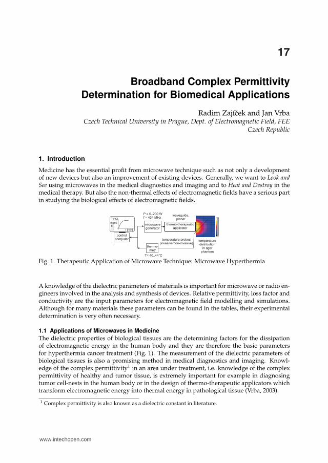
Medicine has the essential profit from microwave technique such as not only a developmentof new devices but also an improvement of existing devices. Generally, we want to Look andSee using microwaves in the medical diagnostics and imaging and to Heat and Destroy in themedical therapy. But also the non-thermal effects of electromagnetic fields have a serious partin studying the biological effects of electromagnetic fields.
Fig. 1. Therapeutic Application of Microwave Technique: Microwave Hyperthermia
A knowledge of the dielectric parameters of materials is important for microwave or radio en-gineers involved in the analysis and synthesis of devices. Relative permittivity, loss factor andconductivity are the input parameters for electromagnetic field modelling and simulations.Although for many materials these parameters can be found in the tables, their experimentaldetermination is very often necessary.
1.1 Applications of Microwaves in Medicine
The dielectric properties of biological tissues are the determining factors for the dissipationof electromagnetic energy in the human body and they are therefore the basic parametersfor hyperthermia cancer treatment (Fig. 1). The measurement of the dielectric parameters ofbiological tissues is also a promising method in medical diagnostics and imaging. Knowl-edge of the complex permittivity1 in an area under treatment, i.e. knowledge of the complexpermittivity of healthy and tumor tissue, is extremely important for example in diagnosingtumor cell-nests in the human body or in the design of thermo-therapeutic applicators whichtransform electromagnetic energy into thermal energy in pathological tissue (Vrba, 2003).
1 Complex permittivity is also known as a dielectric constant in literature.
17
www.intechopen.com

Advanced Microwave Circuits and Systems366
Let’s summarize the basic characteristics of microwaves, their advantages and limitations, andapplications in the medicine:
General characteristic:
• from 100 MHz to 30 GHz frequency range
• diagnostic applications: a tumor detection based on differences in the tissue electricalproperties
• therapeutic applications: a treatment based on the local heating or the regional (whole-body) heating - hyperthermia integrated with MRI, prostate hyperplasia, heart andother tissue ablation, angioplasty
• other applications: radiometry, telemetry, motion detection
Advantages of microwaves:
• offer a wide frequency range
• an ability to focus the energy
• a variety of simulation tools (methods for field solving2)
• a relatively low cost of microwave components and devices
• a low if any health risk
Limitations of microwaves:
• a spatial resolution
• penetration depth of electromagnetic waves
• electromagnetic interferences
Summary of the human characteristics from microwave view point:
• differences in tissue properties (normal/tumor tissue, low/high water content)
• scattering of complex patterns of fields in the body
• individual anatomical differences
1.2 Complex permittivity
The complex permittivity is a quantity which desribes the electrical properties of materials. Incase of non-conductors, dielectrics, the complex permittivity describes an interaction betweenthe dielectric and the applied external electric field.
Polarization
The interaction of an electric field with a biological tissue has the origin in the response ofthe charge particles to the applied field. The displacement of these charge particles fromtheir equilibrium positions gives rise to induced dipoles which respond to the applied field.Such induced polarization arises mainly from the displacement of electrons around nuclei(electronic polarization) or due to the relative displacement of atomic nuclei because of the
2 FEM - Finite Element Method is utilized mostly in frequency domain, body parts are represented bysurfaces and volumes are divided into tetrahedrons. FDTD - Finite Difference in Time Domain utilizedvoxel representation of body tissues.
www.intechopen.com

Broadband Complex Permittivity Determination for Biomedical Applications 367
unequal distribution of charge in molecule formation (atomic polarization). In addition toinduced dipoles some dielectrics, known as polar dielectrics, contain permanent dipoles dueto the asymmetric charge distribution of unlike charge partners in a molecule which tend toreorientation under the influence of a changing electric field, thus giving rise to orientationpolarization. Finally, another source of polarization arises from charge build-up in interfaces
Fig. 2. Polarization effects at a broad frequency range
between components in heterogeneous systems, termed interfacial, space charge or Maxwell-Wagner polarization. The Maxwell-Wagner polarization and orientation polarization due toan alternating electric field together with d.c. conductivity are the basic of thermal effect ofmicrowaves (Kittel, 1966).Permittivity is known from the physics or theory of electromagnetic field as
ε = ε0εc (1)
where ε0 is free space permittivity and εc is complex relative permittivity (dielectrics are veryoften lossy). Complex relative permittivity can be given in turn as
εc = εr − jεrtan δ (2)
where εr is a real part of complex relative permittivity3 and tan δ is the loss factor. For purelyconductive losses
tan δ =σ
ωε0εr(3)
applies, where σ is the medium conductivity.
Derivation of Complex Permittivity
It would be helpful if, through some elementary analysis, the complex nature of permittivity isdemonstrated without having to assume this premise from the start. Amper’s circuital law inits elementary form contains all the necessary components needed for this analysis. Maxwellmodified Ampere’s law by including a displacement current density term for sinusoidal elec-tric field variations
rotH = J + jωD (4)
3 The real part of complex relative permittivity is very often called only relative permittivity. One mustcarefully consider where it is possible (for example for the simplification of terms) to reduce complexrelative permittivity to only relative permittivity.
www.intechopen.com

Advanced Microwave Circuits and Systems368
where H is magnetic field strength, J is current density, D is electric flux density and t is time.The conduction current density is a function of the electric field vector (Ohm’s law)
J = σE (5)
where σ is medium conductivity. Using material formula D = εE and ε = ε0εr is
rotH = σE + jωε0εrE = jωε0E
(
εr +σ
jωε0
)
= jωε0E
(
εr − jσ
ωε0
)
(6)
Complex relative permittivity is finally expressed
εc = ε
′
r − jε′′
r = εr − jσ
ωε0(7)
1.3 Complex permittivity determinaton
A more or less extensive tabulation of the dielectric properties of materials selected to illustratethe theoretical deliberations provided by the authors is common to all papers in the fieldof complex permittivity measurement. Nowadays, papers are instigated for example by theneed for such information for electromagnetic dosimetry. To date there is no consensus on thedielectric data (Gabriel, 1996).Systems using complex permittivity measurement exist, and some are even commerciallyavailable (e.g. the Agilent Technologies 85070 analyzer) but the Czech Technical Universityin Prague is not equipped with this type of material measurement system. Our work is moti-vated by the need for cheap4 but accurate determination of the complex permittivity with themeasurement technique which is also easy to manufacture and therefore would be interestingfor many researchers.
Fig. 3. This illustrates the principle of the reflection method - a medical diagnostics and imag-ing concept using microwaves. The different equivalent penetration depths of microwaves atdifferent frequencies enable us to diagnose the tissues (layers) in the area under treatment.
2. Materials and Methods
There are several methods for measuring the complex permittivity - the resonance method,measurement in free space and the transmission line method (Fig. 4). If we want to usea broadband measurement method that is non-destructive and non-invasive, we shouldchoose a reflection method on an open-ended coaxial line-a method based on the reflectioncoefficient measurement of an open-ended coaxial line attached to the sample of the measureddielectric.
4 The cost of mentioned Agilent system is $5000 approximately, http://www.agilent.com.
www.intechopen.com

Broadband Complex Permittivity Determination for Biomedical Applications 369
Fig. 4. Complex permittivity determination in a broad frequency band
2.1 Reflection Coefficient
Reflection coefficient relates the tangential components of the incident and the reflected elec-tric fields and is a frequency dependent and complex quantity5
Γ =Er
Ei
(8)
where Er is the reflected wave and Ei is the incident wave (Novotný, 2005).
Fig. 5. Frequency behavior of the reflection coefficient
In case of interface between two materials with different impedances, the reflection coefficientis defined
Γ =Z1 − Z0
Z1 + Z0(9)
5 It is important to note the reflection coefficient is a voltage quantity and it is related to a power quantitywith the term ΓP ≈ Γ
2. It is possible to find the reflection coefficient as R, Γ or S11 in technical literature.
www.intechopen.com

Advanced Microwave Circuits and Systems370
where Z0 and Z1 are impedances of materials-in described measurement technique theimpedance of coaxial line is Z0 = 50 Ω and the impedance of a MUT sample is Z1 (gener-ally complex impedance).
2.2 Relation between Reflection and Permittivity
The reflection method entails the measurement of the reflection coefficient on the interfacebetween two materials, on the open end of the coaxial line (as a detector) and the materialbeing tested (MUT, Fig. 6). It is a well-known method for determining dielectric parameters
Fig. 6. Dielectric measurement from the viewpoint of electromagnetic field theory and wavepropagation on the interface between the coaxial probe and the MUT
(Stuchly et al., 1982). This method is based on the fact that the reflection coefficient of an open-ended coaxial line depends on the dielectric parameters of the MUT that is attached to it. Tocalculate the complex permittivity from the measured reflection coefficient, it is useful to usean equivalent circuit of an open-ended coaxial line. Fig. 6 shows the complex permittivitymeasurement from the point of view of electromagnetic field theory and the propagation ofthe electromagnetic wave on the interface between two materials with different impedances(Novotný, 2001). The probe translates changes in the permittivity of a MUT into changes inthe input reflection coefficient of the probe.
Fig. 7. Reflection coefficient versus relative permittivity
The reflection coefficient is varying a lot for the small values of relative permittivity (approx-imately less then 20, Fig. 7). Complex permittivity measurement is more sensitive and henceprecise. Conversely, for high values of relative permittivity (for example between 70 and 90)there is a little change of the reflection coefficient and the measurement has more uncertainties.
www.intechopen.com

Broadband Complex Permittivity Determination for Biomedical Applications 371
The interface between the measurement probe and a MUT sample represents an impedancejump because of biological tissues have extremely high permittivity values. At low frequen-cies their permittivity can be more than 100 and the value of the loss factor more than 0.1. Anaccurate evaluation is very difficult because the reflection coefficient is close to 1 (Fig. 5). Thismeans that only a very small part of the incident energy penetrates into the sample.The surface of the sample of MUT must be in perfect contact with the probe. The thickness ofa measured sample must be at least twice an equivalent penetration depth of the electromag-netic wave d. This ensures that the waves reflected from the far MUT interface are attenuatedby approximately -35 dB, which assures that their effect on the measured reflection coefficientis insignificant.
d =
√
2
ωµσ=
1
ω
√
2
µε0εrtan δ(10)
The dependence of equivalent penetration depth d on dielectric parameters εr and tan δ andalso frequency f denotes Eq. 10. Typical values of d for distilled water and biological muscletissue at different frequencies are summarized in Tab. 1.
Materials f (MHz) 2d (mm)
distilled water434 71.2915 34.02450 12.8
muscle tissue434 25.9915 24.22450 15.6
Table 1. Equivalent penetration depth of the electromagnetic wave into different materials:distilled water and muscle tissue
2.3 Coaxial Probes
When a wave has only transverse field components for both the electric and magnetic fieldand no longitudinal components (Ez = 0 and Hz = 0), the wave is transverse electromagnetic(TEM). Transverse electromagnetic waves are very much appreciated in practice because they
Fig. 8. Coaxial transmission line.
www.intechopen.com

Advanced Microwave Circuits and Systems372
have only four components, with no longitudinal components. On the other hand, uniformplane waves also characterize a very simple structure. As an example, the very well knowncoaxial cable has a TEM wave as the main propagating mode (Fig. 8). The surface of constantphase is indeed a plane, perpendicular to the direction of propagation, hence the wave isplanar. The field, however, is not constant over the plane because it varies between the twoconductors according to a 1/r law. Hence, the TEM wave in a coaxial cable is a nonuniformplane wave.
N&SMA Connector Type Probe
N type coaxial connectors are medium size units which have constant 50 Ω impedance andprovide radio frequency performance up to 11 GHz. SMA (SubMiniature, version A) connec-tors are coaxial RF connectors developed as a minimal connector interface for coaxial cablewith a screw type coupling mechanism. The connector has a 50 Ω impedance. It offers excel-lent electrical performance from DC to 18 GHz.
Fig. 9. Measurement coaxial probe: description and dimensions - inner/outer diameter:N connector type probe 3/7 mm, SMA connector type probe 1.3/4 mm
We have adapted the standard N and SMA connectors for this measurement method fromwhich the parts for connecting to a panel were removed (Fig. 9). The measurement probecan be described by the equivalent circuit consisting of fringing capacitance between innerand outer conductor out of the coaxial structure and radiating conductance which representspropagation losses (Fig. 10). The capacitance and conductance are frequency and permittivitydependent and are also dependent on the dimensions (inner and outer diameters) of the probe.
Fig. 10. An equivalent circuit of the open end of coaxial line: admittance of the probe Y hastwo components - fringing capacitance C and radiating conductance G
A measurement probe can be described as an antenna with the input admittance (Y = G + jB,where G is conductance and B is susceptance) expressed as
Y0 = G0 (εc, ω) + jωC0 (εc, ω) (11)
www.intechopen.com
Broadband Complex Permittivity Determination for Biomedical Applications 373
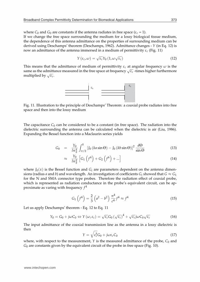
where C0 and G0 are constants if the antenna radiates in free space (εc = 1).If we change the free space surrounding the medium for a lossy biological tissue medium,the dependence of this antenna admittance on the properties of surrounding medium can bederived using Deschamps’ theorem (Deschamps, 1962). Admittance changes - Y (in Eq. 12) isnow an admittance of the antenna immersed in a medium of permittivity εc (Fig. 11)
Y (εc, ω) =√
εcY0 (1, ω
√εc) (12)
This means that the admittance of medium of permittivity εc at angular frequency ω is thesame as the admittance measured in the free space at frequency
√εc -times higher furthermore
multiplied by√
εc.
Fig. 11. Illustration to the principle of Deschamps’ Theorem: a coaxial probe radiates into freespace and then into the lossy medium
The capacitance C0 can be considered to be a constant (in free space). The radiation into thedielectric surrounding the antenna can be calculated when the dielectric is air (Liu, 1986).Expanding the Bessel function into a Maclaurin series yields
G0 =Y0
ln ab
∫ 0
π/2[J0 (ka sin Θ)− J0 (kb sin Θ)]2
dΘ
sin Θ(13)
≈Y0
ln ab
[
G1
(
f 4)
+ G2
(
f 6)
+ ...]
(14)
where J0(x) is the Bessel function and Gi are parameters dependent on the antenna dimen-sions (radius a and b) and wavelength. An investigation of coefficients Gi showed that G ≈ G1
for the N and SMA connector type probes. Therefore the radiation effect of coaxial probe,which is represented as radiation conductance in the probe’s equivalent circuit, can be ap-proximate as varing with frequency f 4
G1
(
f 4)
=2
3
(
a2 − b2)
π4
c4f 4 ≈ f 4 (15)
Let us apply Deschamps’ theorem - Eq. 12 to Eq. 11
Y0 = G0 + jωC0 ⇔ Y (ω, εc) =√
εcG0 (√
εc)4 +
√εc jωC0
√εc (16)
The input admittance of the coaxial transmission line as the antenna in a lossy dielectric isthen
Y =√
ε5cG0 + jωεcC0 (17)
where, with respect to the measurement, Y is the measured admittance of the probe, C0 andG0 are constants given by the equivalent circuit of the probe in free space (Fig. 10).
www.intechopen.com

Advanced Microwave Circuits and Systems374
Admittance Y is related to the measured reflection coefficient S11
Y = Y01 − S11
1 + S11(18)
where Y0 = 1/(50) Ω = 0.02 S is the characteristic admittance of the probe.The usable frequency range of the Eq. 17 results from the theory of wave propagation on themicrowave transmission line. The incident wave is in TEM mode. The equivalent circuit ofthe probe consisting of the fringing capacitor is useful for a low frequency range. The higherorder modes excited at the discontinuity can be various TM0n modes. The equivalent circuitof the probe consisting of fringing capacitance and radiating conductance is useful in the fre-quency range above approximately 1 GHz. The range of the operation can be better definedand extended by a field analysis summing a series of TM modes needed to meet boundaryconditions at the probe face. TM01 is the lowest circular symmetric mode which sharply in-creases the loss by radiation. Measurement probes are under investigation in the frequencyrange from 300 kHz (TEM, fringing field) to 3 GHz (TM01, also radiating conductance).The equivalent circuit has an imperfectly defined range of frequency and permittivity in whicha specified uncertainty can be achieved. Equivalent circuits of the probe never take accountof the finite MUT sample and finite ground plane flange which give rise to resonances in theresponse.The method of solving the complex Eq. 17 consists of splitting it into real and imaginary parts,thereby obtaining a set of two real nonlinear equations for the two real unknowns, which areeither C0 and G0 (when calibrating the probe) or the real and imaginary part of the complexpermittivity εc of the MUT. To break this down into stages:
• splitting of Eq. 17 into real and imaginary parts
• to obtain C0 and G0, admittance Y for a material with a known complex permittivityεc (e.g. distilled water) is measured and the set of two equations is solved for the un-knowns C0 and G0
• to measure of complex permittivity, the admittance Y of a MUT is measured and the setof the two equations in solved for the unknown real and imaginary parts of the εc
2.4 Modeling and Simulations
An evaluation of this measurement method involves numerical calculation and modeling(Fig. 13). A numerical simulation based on a Finite Integration Technique (FIT, (CST, 2009)) isused to calculate the reflection coefficient on the interface between the probe and the sampleof a MUT (Hudlicka, 2006). The system that we modeled consists of two parts, i.e. the sensorand the sample of MUT. The modeling is focused on a model with distilled water - the Debyemodel of distilled water is implemented (Eq. 19). This model was also used for the evaluationof measurement uncertainty.
Choice of Reference Liquid
The material model of distilled water was recognized by Debye in 1926 and describes thecomplex permittivity of distilled water as a function of frequency.
εc = ε
′
r − jε′′
r = ε∞ +εs − ε∞
1 + jωτ
(19)
108 1010 10120
10
20
30
40
50
60
70
80
f (Hz)
com
plex
per
mitt
ivity
distilledwaterhuman
blood
real part ofcomplex
permittivity
imaginary partof complexpermittivity
www.intechopen.com

Broadband Complex Permittivity Determination for Biomedical Applications 375
where ε∞ is optical permittivity at high field frequencies, εs is static permittivity at low fieldfrequencies and τ is electrical relaxation time (a measure of molecules and dipoles mobility).The values of these parameters for distilled water are: ε∞= 4.6, εs = 78.3 and τ = 8.07 ps.The condition that a reference material should have similar dielectric properties as the MUT-Ubiological tissue, could not be totally fulfilled because of the very high values of the realpart of complex permittivity of biological tissues and their lossy character.
108 1010 10120
10
20
30
40
50
60
70
80
f (Hz)
com
plex
per
mitt
ivity
distilledwaterhuman
blood
real part ofcomplex
permittivity
imaginary partof complexpermittivity
Fig. 12. Dielectric behavior of distilled water and human blood
Fig. 12 shows dielectric properties of the distilled water and the human blood. Distilled waterhas high values of the real part of complex permittivity and very low values of the imaginarypart. Therefore the distilled water is useful reference liquid mainly for the determination ofthe real part of complex permittvity but neither this condition cannot be satisfied in the wholeexpected frequency range. Another used reference liquids are alcohols for the dielectric mea-surements. Unfortunately, an alcohol as a hygroscopic liquid is a time unsteady caliber. Ad-ditionaly, the dielectric parameters are known from the tables for only 100 % virgin alcohols.Their use in the calibration makes measurements not very precise.
De-embedding the Measurement System
EM field simulation provides information about the reflection coefficient Γ at a reference planeof the excitation port but in order to calculate complex permittivity, the measurement tech-nique needs to obtain the reflection coefficient (Γx = S11) on the interface between the probeand the MUT sample (Fig. 13). In addition, the measurement probe represents an inhomoge-
Fig. 13. A model of a reflection coefficient measurement: one-port network (reflection mea-surement) and the de-embedding of the measurement system
neous transmission line. It is not possible to shift simply the reference plane because of the
www.intechopen.com

Advanced Microwave Circuits and Systems376
different dielectric materials (air and teflon) inside the N connector. It is therefore necessary toperform a de-embedding procedure for the measurement system in order to obtain the correctphase information of the reflection coefficient. Fig. 14 shows the comparison of original datafrom the numerical modelling and also the measurement with the de-embedded data in theSmith chart. The difference is obvious.
Fig. 14. Comparison of original and de-embedded data: values valid for the agar phantommaterial
2.5 Measurement System
A typical measurement system using the reflection method on an open-ended coaxial lineconsists of the network analyzer, the coaxial probe and software. Our measurements (Zajícek,2009) were done with the aid of an Agilent 6052 network analyzer in the 300 kHz to 3 GHzfrequency range. The coaxial probe is placed in contact with a MUT (Fig. 15). Complex per-mittivity measurement is very fast and proceeds through the three stages. First the calibrationof vector network analyzer (VNA) is performed. Then the calibration is carried out using a ref-erence material (with the known dielectric constant εc). And, finally, the reflection coefficientof MUT is measured. The complex permittivity of MUT is evaluated with the aid of a PC (inour case using MatLab).
2.6 Calibration Kit for Vector Measurement
A calibration kit is a set of physical devices called standards. Each standard has a preciselyknown or predictable magnitude and phase response as a function of frequency. To be able to
www.intechopen.com
Broadband Complex Permittivity Determination for Biomedical Applications 377
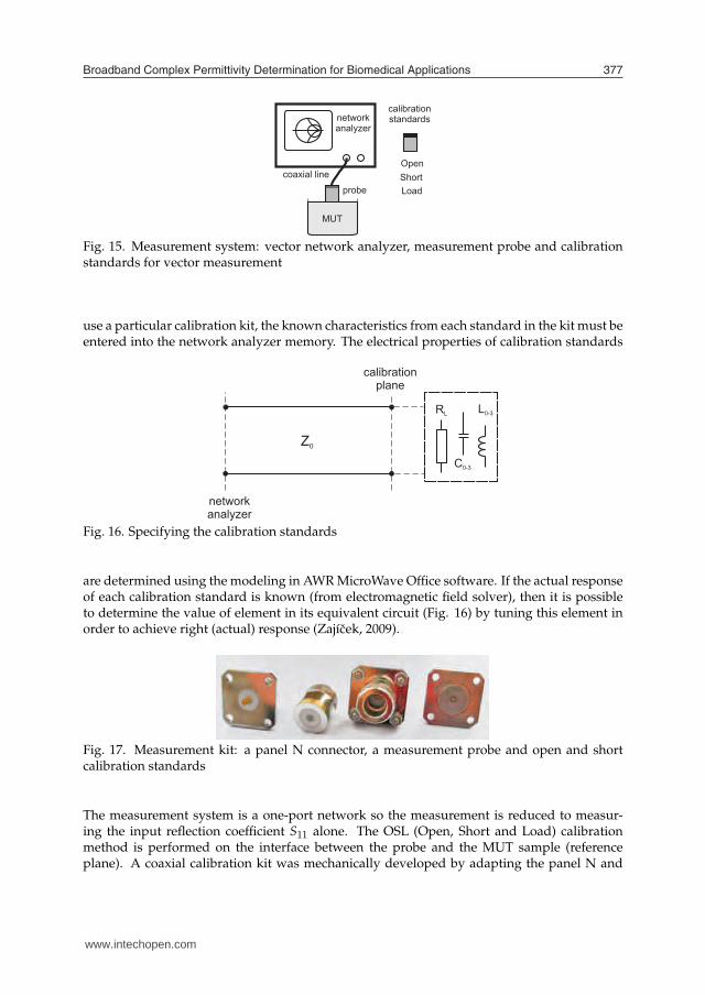
Fig. 15. Measurement system: vector network analyzer, measurement probe and calibrationstandards for vector measurement
use a particular calibration kit, the known characteristics from each standard in the kit must beentered into the network analyzer memory. The electrical properties of calibration standards
Fig. 16. Specifying the calibration standards
are determined using the modeling in AWR MicroWave Office software. If the actual responseof each calibration standard is known (from electromagnetic field solver), then it is possibleto determine the value of element in its equivalent circuit (Fig. 16) by tuning this element inorder to achieve right (actual) response (Zajícek, 2009).
Fig. 17. Measurement kit: a panel N connector, a measurement probe and open and shortcalibration standards
The measurement system is a one-port network so the measurement is reduced to measur-ing the input reflection coefficient S11 alone. The OSL (Open, Short and Load) calibrationmethod is performed on the interface between the probe and the MUT sample (referenceplane). A coaxial calibration kit was mechanically developed by adapting the panel N and
www.intechopen.com

Advanced Microwave Circuits and Systems378
Fig. 18. Measurement kit: a panel SMA connector, a measurement probe, open, short andmatched (50 Ω) load calibration standards
SMA connectors in the same way as the measurement probe (Fig. 17 and Fig. 18). The shortstandard is made by the connector which is shorted in the measurement plane by a metalplate. The coaxial open standard is created by two connectors (second one represents the aircavity) and the load standard is a commonly used 50 Ω termination.
3. Step-by-Step Measurement Procedure
The measurement stages for the MUT are:
• to calibrate the network analyzer
• to measure S11 for a substance with a known εc (distilled water), to compute Y usingEq. 18 and, solving Eq. 17 as outlined above, to determine the constants C0 and G0
• to measure S11 for any desired MUT, to compute Y (Eq. 18) and to solve Eq. 17 for theunknown real and imaginary part of complex permittivity εc. Since the equations areof 5th order in terms of εc, care must be taken to select the physically correct solution(positive real part and negative imaginary part of the εc)
• if needed, to derive any quantities of interest, such as relative permittivity εr, loss factortan δ or conductivity σ from the εc
4. Uncertainty Analysis
The result of dielectric measurement is only an approximation or estimate of the value ofthe complex permittivity and thus the result is only complete when it is accompanied bya quantitative statement of its uncertainty.If the measurement device taken to include measurement standards and reference materialsis tested through a comparison with a known reference standard and the uncertainties asso-ciated with the standard are assumed to be negligible relatively to the required uncertaintyof the test, the comparison is viewed as determining the error of the device. The referencestandard is the Debye model of distilled water and the standard and combined standarduncertainty of the complex permittivity determination of distilled water is evaluated in thefollowing section.Sources of an uncertainty are distinguished from the view point of measurement technique.The measurement technique is based on the measurement of the reflection coefficient withthe aid of a vector network analyzer. Generally, the calibration of network analyzer and thecalibration of measurement probe by means of reference liquid is considered. Last but notleast, the condition as a location of coaxial cable which connects the network analyzer withthe probe is assumed as a possible contribution to the uncertainty.
www.intechopen.com

Broadband Complex Permittivity Determination for Biomedical Applications 379
This uncertainty evaluation is also the verification of self-consistency of the developed relationbetween the measured reflection coefficient and the calculated complex permittivity (Eq. 17).Uncertainty evaluation is based on the relevant information available from previous mea-surement data and experience and knowledge of the behavior and property of the distilledwater, and the measurement instruments used (referred to as Type B uncertainty evaluation).Sources of uncertainties and related standard and combined standard uncertainties (Tab. 2and 3) are evaluated with the aid of guidelines (NIST, 1999).
source of uncertainty f (MHz) standard uncertainty (%)
repeated observations30 0.26
434 0.29915 0.34
random effects30 4.93
434 2.16915 3.67
systematic effects30 1.01
434 0.58915 4.50
combined standard uncertainty30 5.12
434 2.29915 5.90
Table 2. The uncertainty budget, N-type probe: sources of measurement uncertainty are eval-uated at important frequencies from a medical point of view
source of uncertainty f (MHz) standard uncertainty (%)
repeated observations
434 0.33915 0.291800 0.192450 0.37
random effects
434 3.06915 2.931800 2.812450 2.14
systematic effects
434 0.58915 0.671800 3.692450 20.9
combined standard uncertainty
434 3.19915 3.071800 4.722450 21.3
Table 3. The uncertainty budget, SMA-type probe: sources of measurement uncertainty areevaluated at important frequencies from a medical point of view
www.intechopen.com

Advanced Microwave Circuits and Systems380
The applied recommendations given in (NIST, 1999) and mentioned also above are following:
• RepeatabilityThe measurement procedure was performed twenty times over a short period of time(minutes) in a single location with the one-off application of measuring instruments inorder to observe the same results.
• Random EffectsThe measurement procedure was performed ten times over a long period of time (daysand months) at a single location with the different application of measuring instrumentsin order to observe different results. The conditions are generally changed by locatingthe coaxial cable in a different position between the measurement probe and the net-work analyzer. The calibration of the network analyzer was performed before eachmeasurement as well as the calibration of the measurement probe by means of distilledwater.
It is important to note that complex permittivity is a variable quantity - it changes with fre-quency, temperature, mixture, pressure and the molecular structure of the MUT. Frequencyhas a significant influence on changes in the complex permittivity of biological substances.This is the reason for evaluating the uncertainties separately at each frequency of interest formicrowave applications.
5. Results
The relative permittivity of lossy materials is a heavily frequency-dependent quantity. Be-cause of the decreasing ability of particles to follow rapid changes of electrical field, the rela-tive permittivity decreases with increasing frequency. The frequencies in the following tableshave been selected because of their interest from an industrial, scientific and medical point ofview.
5.1 Home-made phantom material
Human tissues can be classified into those with high water content such as muscle, brain,and the internal organs and those with low water content such as fat and bone. The presentbiological tissue-equivalent phantom6 simulates the characteristics of the high-water-contenttissues.
ingredients weight (g)
de-ionized water 3375agar gelatine 104.6solidum chloride (NaCl) 37.60sodium azide (NaN3) 2.000TX-151 84.40polyethylene powder 337.5
Table 4. The composition of the agar phantom - ingredients for developing a biological muscletissue-equivalent
6 This phantom material was manufactured by Tomáš Dríždal at the Department of Radiation Oncology,Erasmus MC - Daniel den Hoed Cancer Center, Rotterdam.
www.intechopen.com

Broadband Complex Permittivity Determination for Biomedical Applications 381
The tissue-equivalent phantom can be made of agar, deionized water, polyethylene powder,sodium chloride (NaCl), TX-151, and sodium azide (NaN3) (Tab. 4). The polyethylene pow-der is used to adjust the relative permittivity while the conductivity is mainly adjusted by thesodium chloride concentration. Since the agar solution and the polyethylene powder cannotbe mixed directly, TX-151 is used to increase the viscosity. Sodium azide is added as a preser-vative. The advantages of this particular phantom are the ease of use of the original materialsand the possibility of manual processing with no need for special production equipment. Itis also easy to machine and to cut into arbitrary shapes. The phantom maintains its shapeand is mechanically strong. By manipulating the agar, a certain amount of adjustment of themechanical strength is possible. Hence, this phantom is useful for splitting the phantoms.
f (MHz) εr (-) tan δ (-) σ (S/m)
434 60.9 0.86 1.26915 58.6 0.54 1.601800 53.1 0.47 2.502450 48.5 0.48 3.14
Table 5. Dielectric parameters of a home-made muscle tissue phantom
The electrical parameters of the muscle tissue equivalent are described in Tab. 5. Differentvalues of these biological parameters may be required for experimental work. For this reason,it is desirable that the electrical characteristics of the phantom be adjustable within a certainrange. In this phantom, the electrical characteristics can be adjusted to a certain extent bymodifying the composition shown in Tab. 4. Hence, phantoms are fabricated with varyingamounts of polyethylene powder and sodium chloride in order to adjust their permittivitycharacteristics. To facilitate mixing the polyethylene powder into the agar solution in orderto enable the smooth fabrication of the phantom, the amount of TX-151 is dependent on theamount of polyethylene powder. The conductivity is affected by both the polyethylene andsodium chloride whereas the relative permittivity is mainly determined by the polyethylene.Hence, the composition of the phantom with a desired characteristic can be determined firstby deriving the amount of polyethylene needed for the desired relative permittivity and thenadjusting the conductivity by means of sodium chloride. More details can be found in (Koichi,2001).
5.2 Commercially available phantom material
This phantom is a tissue-equivalent material, in this case an equivalent of biological muscletissue. An agar phantom (agar gelatine) is the most commonly used phantom in the testing ofthermotherapy applicators, and the use of the phantoms is significant in the measurement ofimpedance matching and Specific Absorption Rate (SAR).
www.intechopen.com
Advanced Microwave Circuits and Systems382
f (MHz) εr (-) tan δ (-) σ (S/m)
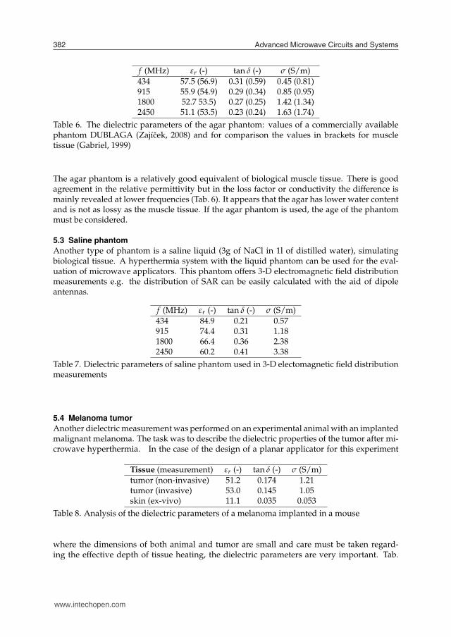
434 57.5 (56.9) 0.31 (0.59) 0.45 (0.81)915 55.9 (54.9) 0.29 (0.34) 0.85 (0.95)1800 52.7 53.5) 0.27 (0.25) 1.42 (1.34)2450 51.1 (53.5) 0.23 (0.24) 1.63 (1.74)
Table 6. The dielectric parameters of the agar phantom: values of a commercially availablephantom DUBLAGA (Zajícek, 2008) and for comparison the values in brackets for muscletissue (Gabriel, 1999)
The agar phantom is a relatively good equivalent of biological muscle tissue. There is goodagreement in the relative permittivity but in the loss factor or conductivity the difference ismainly revealed at lower frequencies (Tab. 6). It appears that the agar has lower water contentand is not as lossy as the muscle tissue. If the agar phantom is used, the age of the phantommust be considered.
5.3 Saline phantom
Another type of phantom is a saline liquid (3g of NaCl in 1l of distilled water), simulatingbiological tissue. A hyperthermia system with the liquid phantom can be used for the eval-uation of microwave applicators. This phantom offers 3-D electromagnetic field distributionmeasurements e.g. the distribution of SAR can be easily calculated with the aid of dipoleantennas.
f (MHz) εr (-) tan δ (-) σ (S/m)
434 84.9 0.21 0.57915 74.4 0.31 1.181800 66.4 0.36 2.382450 60.2 0.41 3.38
Table 7. Dielectric parameters of saline phantom used in 3-D electomagnetic field distributionmeasurements
5.4 Melanoma tumor
Another dielectric measurement was performed on an experimental animal with an implantedmalignant melanoma. The task was to describe the dielectric properties of the tumor after mi-crowave hyperthermia. In the case of the design of a planar applicator for this experiment
Tissue (measurement) εr (-) tan δ (-) σ (S/m)
tumor (non-invasive) 51.2 0.174 1.21tumor (invasive) 53.0 0.145 1.05skin (ex-vivo) 11.1 0.035 0.053
Table 8. Analysis of the dielectric parameters of a melanoma implanted in a mouse
where the dimensions of both animal and tumor are small and care must be taken regard-ing the effective depth of tissue heating, the dielectric parameters are very important. Tab.
www.intechopen.com

Broadband Complex Permittivity Determination for Biomedical Applications 383
Fig. 19. Microwave hyperthermia: experimental therapy on a laboratory mouse, measurementof the dielectric parameters of an implanted tumor
8 summarizes results measured at a frequency f = 2.45 GHz. The tumor dimensions were30x18 mm. Hyperthermia was applied for a period of 15 minutes with a continual power of30 W and the achieved temperature in the tumor was 45 oC.
5.5 Biological tissue
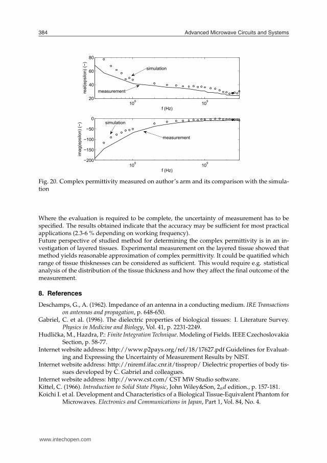
Fig. 20 summarizes the values measured on the author’s arm and values modeled usinga four-layered model of biological tissue. The simulation and the measurement values arebased on a model and in vivo sample respectively, these being inhomogeneous (layered). Mi-crowave applicators are usually designed and tested on the agar phantom described in thesection below as a homogeneous equivalent of biological muscle tissue. This disparity mayaffect the impedance matching of microwave applicators. If the complex permittivity of thelayered treated area is considered in the design of applicators, a more realistic impedancematching could be achieved.
6. Limitations
Complex relative permittivity is used in calculations of electromagnetic field distribution andis inversely related to the square root in these calculations. This means that the measurementuncertainties from Tab. 2 and 3 are further suppressed. No evaluation of the measurementuncertainties in the case of determining the imaginary part of complex permittivity is pre-sented. For distilled water, this imaginary part has extremely low values (lower than 1) andany evaluation is difficult - there is a high level of uncertainty when is only a small differencebetween the measured and Debye values.
7. Conclusion
The complex permittivity determination based on reflection coefficient measurement is suit-able for the determination of the dielectric parameters of materials in wide bands. Thismethod was described from the viewpoint of electromagnetic field theory and the coaxialprobes were described with the equivalent circuit as an antenna in a lossy medium respectingradiation effects at higher frequencies. Some materials were measured and where possiblethe comparison between measurement (modeling) and values from tables was carried out.
www.intechopen.com
Advanced Microwave Circuits and Systems384
108 10920
40
60
80
f (Hz)
real
(eps
ilon)
(−)
108 109−200
−150
−100
−50
0
f (Hz)
imag
(eps
ilon)
(−)
measurement
simulation
simulation
measurement
Fig. 20. Complex permittivity measured on author’s arm and its comparison with the simula-tion
Where the evaluation is required to be complete, the uncertainty of measurement has to bespecified. The results obtained indicate that the accuracy may be sufficient for most practicalapplications (2.3-6 % depending on working frequency).Future perspective of studied method for determining the complex permittivity is in an in-vestigation of layered tissues. Experimental measurement on the layered tissue showed thatmethod yields reasonable approximation of complex permittivity. It could be quatified whichrange of tissue thisknesses can be considered as sufficient. This would require e.g. statisticalanalysis of the distribution of the tissue thickness and how they affect the final outcome of themeasurement.
8. References
Deschamps, G., A. (1962). Impedance of an antenna in a conducting medium. IRE Transactionson antennas and propagation, p. 648-650.
Gabriel, C. et al. (1996). The dielectric properties of biological tissues: I. Literature Survey.Physics in Medicine and Biology, Vol. 41, p. 2231-2249.
Hudlicka, M., Hazdra, P.: Finite Integration Technique. Modeling of Fields. IEEE CzechoslovakiaSection, p. 58-77.
Internet website address: http://www.p2pays.org/ref/18/17627.pdf Guidelines for Evaluat-ing and Expressing the Uncertainty of Measurement Results by NIST.
Internet website address: http://niremf.ifac.cnr.it/tissprop/ Dielectric properties of body tis-sues developed by C. Gabriel and colleagues.
Internet website address: http://www.cst.com/ CST MW Studio software.Kittel, C. (1966). Introduction to Solid State Physic, John Wiley&Son, 2nd edition., p. 157-181.Koichi I. et al. Development and Characteristics of a Biological Tissue-Equivalent Phantom for
Microwaves. Electronics and Communications in Japan, Part 1, Vol. 84, No. 4.
www.intechopen.com
Broadband Complex Permittivity Determination for Biomedical Applications 385
108 10920
40
60
80
f (Hz)
real
(eps
ilon)
(−)
108 109−200
−150
−100
−50
0
f (Hz)
imag
(eps
ilon)
(−)
measurement
simulation
simulation
measurement
Liu L., X. et al. (1986). Improvement in Dielectric Measurement Technique of Open-endedCoaxial Line Resonator Method. Electronics Letters, Vol. 22, No. 7, p. 373-375.
Novotný, K. (2005). Theory of Electromagnetic Field, Press CTU in Prague.Novotný, K. (2001). Theory of Electromagnetic Field II: Field and Waves, Press CTU in Prague.Stuchly M., A. et al. (1982). Measurement of RF permittivity of biological tissue with an opend-
ended coaxial line: Part II-Experimental results. IEEE transactions on MTT, Vol. 30,no.1, p. 82-92.
Vrba, J. (2003). Medical applications of microwave technique, Press CTU in Prague, p. 46-61.Zajícek, R. et al. (2008). Broadband Measurement of Complex Permittivity Using Reflection
Method and Coaxial Probes. Radioengineering, Vol. 17, No. 1, p. 14-19, ISSN 1210-2512.Zajícek, R. (2009). Application of Complex Permittivity in Medical Diagnostics and Imaging, Doc-
toral Thesis, CTU in Prague.
www.intechopen.com

Advanced Microwave Circuits and Systems386
www.intechopen.com
Advanced Microwave Circuits and SystemsEdited by Vitaliy Zhurbenko
ISBN 978-953-307-087-2Hard cover, 490 pagesPublisher InTechPublished online 01, April, 2010Published in print edition April, 2010
InTech EuropeUniversity Campus STeP Ri Slavka Krautzeka 83/A 51000 Rijeka, Croatia Phone: +385 (51) 770 447 Fax: +385 (51) 686 166www.intechopen.com
InTech ChinaUnit 405, Office Block, Hotel Equatorial Shanghai No.65, Yan An Road (West), Shanghai, 200040, China
Phone: +86-21-62489820 Fax: +86-21-62489821
This book is based on recent research work conducted by the authors dealing with the design anddevelopment of active and passive microwave components, integrated circuits and systems. It is divided intoseven parts. In the first part comprising the first two chapters, alternative concepts and equations for multiportnetwork analysis and characterization are provided. A thru-only de-embedding technique for accurate on-wafer characterization is introduced. The second part of the book corresponds to the analysis and design ofultra-wideband low- noise amplifiers (LNA).
How to referenceIn order to correctly reference this scholarly work, feel free to copy and paste the following:
Radim Zajicek and Jan Vrba (2010). Broadband Complex Permittivity Determination for BiomedicalApplications, Advanced Microwave Circuits and Systems, Vitaliy Zhurbenko (Ed.), ISBN: 978-953-307-087-2,InTech, Available from: http://www.intechopen.com/books/advanced-microwave-circuits-and-systems/broadband-complex-permittivity-determination-for-biomedical-applications

© 2010 The Author(s). Licensee IntechOpen. This chapter is distributedunder the terms of the Creative Commons Attribution-NonCommercial-ShareAlike-3.0 License, which permits use, distribution and reproduction fornon-commercial purposes, provided the original is properly cited andderivative works building on this content are distributed under the samelicense.