british geological survey mineralogy petrology group ... · 2. feldspar 2.1. introduction feldspar...
TRANSCRIPT
BRITISH GEOLOGICAL SURVEY
Mineralogy & Petrology Group
Technical Report No. WG/94/33R
EVALUATION OF LABORATORY METHODOLOGIES FOR
FROTH FLOTATION OF FELDSPAR AND KAOLIN
Date
16th September 1994
Classification
Geographical index
Scotland, Thailand, Zambia
Subject index
Feldspar, Kaolin, Froth flotation,
Mineral processing
Bibliographic reference
Mitchell, CJ (1994)
Evaluation of methodologies for
froth flotation of feldspar and kaolin
British Geological Survey
Technical Report WGI94133R
C J Mitchell
©NERC 1994 British Geological Survey, Keyworth, Nottingham NG12 5GG, UK

This report has been generated from a scanned image of the document with any blank pages removed at the scanning stage. Please be aware that the pagination and scales of diagrams or maps in the resulting report may not appear as in the original

BRITISH GEOLOGICAL SURVEY
Mineralogy & Petrology Group
Technical Report WG/94/33R
Evaluation of methodologies for froth flotation of feldspar and kaolin
CJ Mitchell
1. INTRODUCTION
1.1. Aims
This report describes work carried out to establish and evaluate methodologies for the
laboratory froth flotation of feldspar and kaolin. One of the main aims was to ascertain the
feasibility of separating glass-grade feldspar from granite quarry dust and [meso As part of this,
a method for HF-free froth flotation of feldspar was evaluated. This work was carried out as
part of the ongoing 'Maintenance of capability in Mineral Sciences' project, 75CB
1.2. Background
Since the 1920s, froth flotation has been widely used in the processing of minerals.
Approximately 2000 million tonnes of solids are treated every year by flotation. The reasons
for its popularity include the capability for high throughput on a continuous basis, relatively
low operating and capital costs, and a wide variety of readily available and proven equipment
and reagents. Also it is a very robust process to operate and control (Klimpel, 1993). Froth
flotation is commonly used in the processing of industrial minerals, especially barite, feldspar,
fluorite, graphite, kaolin, phosphate, potash, silica sand and talc. Unlike metallic minerals,
industrial minerals have low concentration ratios (waste:valuable mineral) in the order of 2 to
3: 1. This encourages the use of gravity, electrostatic, magnetic and heavy media separation, as
well as froth flotation (Crozier, 1990).
Minerals with hydrophobic surfaces attach to air bubbles and float to the top of a pulp (mineral
suspension) to form a mineral froth (Figure 1). This basic principle of froth flotation is known
as coursing bubble or bubble capture flotation (Crozier, 1990). The target mineral is generally
recovered from the froth (direct flotation) although the waste minerals can be removed this way
leaving the valuable minerals to sink (reverse flotation). Chemical reagents, such as collectors,
frothers and modifiers, are used to float specific minerals. Some industrial minerals, such as
talc and graphite, have naturally hydrophobic surfaces and therefore require little in the way of
chemical treatment to make them float. Other industrial minerals, such as feldspar, fluorite and
calcite, have hydrophillic surfaces and therefore do require chemical treatment. Collectors are
used to treat the surfaces of these minerals, these displacing the adsorbed water layers and
forming hydrophobic coatings. Commonly used collectors include low-cost soaps, fatty acids,
amines, quaternary ammonium compounds, sulphonates and petroleum oils. Frothers are
surface active (surfactants) reagents added to the pulp to reduce the surface tension of air
bubbles and help stabilise the mineral froth. Commonly used frothers include pine oil, alcohols
(eg methyl isobutyl carbinol), polyethers, and amines. Many industrial mineral collectors are
surface active and can therefore double as collector and frother. Modifiers are reagents added to
control pH (including lime, sodium carbonate and sulphuric acid), enhance flotation of certain
minerals (activators such as HF), or prevent the flotation of certain minerals (depressants such
as sodium silicate).
Froth flotation is becoming more popular, especially as the economics of mineral extraction
demands the exploitation of lower-grade, fmer-grained deposits. To partly accommodate this,
flotation cells have increased in size (1000+ cubic feet in capacity) which offers reductions in
the cost per tonne of ore processed. Also high capacity, non.,.mechanical flotation devices, such
as columns are being used, generally in scavenger and cleaner operations (Crozier, 1990).
Conventional mechanical flotation machines consist of a square cell with a central impeller,
which simultaneously stirs and draws air into the pulp. Mechanical agitation is required to keep
particles in suspension and promote bubble:particle contact. A relatively undisturbed zone is
also required in order for efficient separation of the mineral froth from the pulp (Figure 1). The
practical outcome is a compromise between the two. In an industrial plant the cells are arranged
in rows, with adjustable weirs between them to allow the passage of mineral froth between
cells. The feed is progressively 'cleaned' as it passes from one cell to the next, progressing
from rougher, scavenger, cleaner and finally to recleaner cells. This is effective in producing
high mineral grade, although inevitably results in a reduction of mineral recovery. Column
flotation machines consist of columns up to 10 metres in height with no mechanical agitation.
The process relies on the counter-current produced between rising air bubbles and downward
moving feed material/wash water. A single column has the capacity of a whole row of
conventional cells. Improved mineral recovery and fines separation are attained due to the
greater residence time and relatively undisturbed nature of the separation.

2. FELDSPAR
2.1. Introduction
Feldspar is a common rock fonning mineral that occurs as Na-, K- and Ca-rich varieties. Na
and K-feldspars (also known as the alkali feldspars) are exploited as raw materials for use in
glass and ceramics as a source of alkalis, alumina and silica. Alkali feldspars are major
constituents of granite (which contain between 50 and 70% feldspar) related rocks, although
these rocks are not normally exploited for their feldspar content. Feldspar of commercial
significance generally occurs as relatively large crystals (>3 cm) free of iron-bearing impurities
and is easily separated from other minerals. These can be found in coarsely-crystalline igneous
rocks such as pegmatite and alaskite.
Industrial-scale processing of feldspar involves the removal of quartz, mica and other iron
bearing impurities. Coarse material may be hand- or photometrically-sorted. Finer material may
be processed by a combination of gravity separation, magnetic separation andlor froth flotation.
Froth flotation of feldspar is carried out under acidic conditions, using amine-based collectors.
HF is generally used as an activator in this process, although the mechanism(s) by which it
enhances flotation are poorly understood. HF may remove weathered material andlor coatings
and form complex silicofluoride andlor alumino fluoride compounds on the clean surface of
feldspar (Manser, 1975). Fluoride salts, such as sodium fluoride, may be used as an alternative
to HF. The use of HF is hazardous, requiring careful handling of reagents and management of
the flotation process. One of the aims of this study was to evaluate a non-HF flotation route
developed by Akzo Nobel, using a specially formulated fatty acid collector.
2.2. Samples
The samples examined as part of this investigation were granite quarry fines from Scotland and
feldspar pegmatite fmes from Takua Pit Thong mine in Thailand. The Scottish granite contains
about 55% alkali feldspar, with the remainder being mainly quartz and a small amount of biotite
mica and other ferromagnesian minerals. Production of glass-grade feldspar from the
stockpiled quarry fines would have a cost advantage over other commercial feldspar products,
as the mining and primary crushing for aggregate production have already been carried out
(Mitchell, CJ & Henney, PJ, 1994; Mitchell, CJ and Evans, EJ, 1995).
The Thai feldspar fines result from the production of ceramic-grade feldspar from granite
pegmatite. The fines consist of dominant microcline feldspar, with major quartz, minor
muscovite mica and trace amounts of tourmaline. The raw material is hand-sorted and material
fmer than 2 cm is being stockpiled. These fmes contain a significant amount of muscovite mica
( -10%) which is too fme to remove by hand. Air classification trials were carried out by BGS
in 1990 and ceramic-grade feldspar concentrates were produced (Mitchell et al., 1990).
However, <500 /lm material cannot be processed using this technique. The effectiveness of
HF-free feldspar flotation in producing a ceramic-grade feldspar concentrate from this material
was tested.
2.3. Methods
A sample of the Scottish granite was examined using both petrological microscope and electron
microprobe to determine the liberation characteristics and chemistry of the feldspar. The
mineralogy, including feldspar liberation size, of the granite was determined by examination of
a polished thin section using a petrological microscope. The modal proportions and size range
of the minerals present were also determined. The major element chemistry of the feldspar was
determined by CAMECA SX50 automated electron microprobe using wavelength dispersive
methods to enhance detection limits.
The mineralogy of the Thai feldspar was determined by X-ray diffraction analysis. The modal
proportions of the minerals present were determined by examination of the products using a
binocular microscope.
The samples were prepared for processing by a combination of screening and/or grinding of
oversize material. The granite fines were split into two processing routes, one using material
sized to 600 to 106 /lm and the other material sized to 300 to 106/lm (Figure 2). Magnetically
susceptible material was removed from the samples by processing using a Carpco high
intensity induced-roll magnetic separator. The non-magnetic products formed the feed material
for froth flotation. The Thai feldspar fines were sized to 500 to 106/lm (Figure 3).
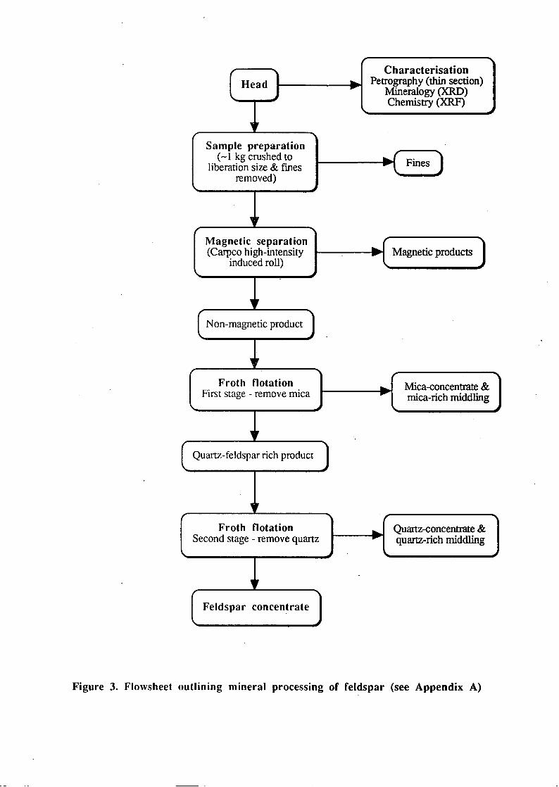
Froth flotation was carried out to produce feldspar concentrates using a two-stage process to
remove the mica and quartz present in the samples (Appendix A). The flotation was carried out
in a pyrex cell using a Denver D12 Laboratory flotation machine. Deionised water was used to
prepare mineral suspensions. The pH was controlled with weak solutions of sulphuric acid and
sodium hydroxide. Excessive frothing during flotation was controlled with heavy distillate
(which partially neutralizes the effect of the surfactant). In the first stage mica was floated away
from the quartz and feldspar. The reagents used were alkylamine acetate (,Arrnoflote 64' from
Akzo Nobel) as collector and methyl isobutyl carbinol (MIBC) as frother. In the second stage
feldspar was floated away from quartz. The reagents used were a fatty acid derivativelButan-2-
01 collector (' Arrnoflote 543', and 'Lilaflot OT 36' in later trials, from Akzo Nobel) and MIBC
as frother. Flotation was repeated several times in order to maximise the amount of separation.
Prior to each repeated flotation the samples were washed in hot water and detergent in order to
remove reagent residues.
The major element chemistry of the feldspar concentrates was determined using a Phillips PW
1480 X-ray fluorescence (XRF) spectrophotometer.
2.4. Results and discussion
2.4.1. Granite feldspar
The froth flotation trials were successful in producing feldspar concentrates from the granite
fines. The 600 to 106 J.1m concentrate contained at least 95% feldspar and 0.19% Fe203. The
300 to 106 J.1m concentrate also contained at least 95% feldspar and 0.26% Fe203. High-grade
by-products were also produced. The 600 to 106J.1m route produced a concentrate grading
about 95% mica. The 300 to 106 J.1m route produced a quartz concentrate containing 99.35%
Si02 and 0.02% Fe203 (Table 1).
The combined magnetic separation / froth flotation route produced feldspar concentrates from
the granite fines with Fe203 contents approaching the specifications of glass-grade feldspar.
Although Fez03 contents of <0.1 % are generally quoted for glass-grade material, levels as high
as 0.2% can be tolerated if the iron content of other raw materials allows. Although initial spot
analyses by EPMA of the granite feldspar suggested a very low iron content, the presence of
fme-grained biotite inclusions appears to be responsible for the slightly higher levels of iron in
the concentrate. Further grinding to liberate this mica would probably produce a concentrate
with a lower iron content, although this would then fall outside the particle-size specifications
for glass-grade feldspar.
Quartz-rich by-products were also produced from the feldspar flotation. The 300 to 106 J.1m
material produced a quartz by-product containing 99.35% Si02, 0.02% Fe203 and 0.01 % Ti02
(Table 1). This is suitable for use in glass making and in the manufacture of sodium silicate.
2.4.2. Thai feldspar
The froth flotation trial was successful in producing a feldspar concentrate from the Thai
feldspar fines which meets the published specifications for ceramic-grade feldspar (Table 2).
The feldspar concentrate contained at least 95% feldspar with 0.09% Fe203. High grade by
products were also produced, including a concentrate grading about 95% mica and a quartz
concentrate containing 97.21 % Si02 and 0.04% Fez03 (Table 2).

2.4.3. Best practice for laboratory flotation of feldspar
It was observed that addition of collector reagent to the sample suspensions (worked on in this
report) invariably caused vigorous 'flocculation', with large aggregates forming, even during
intense stirring of the pulp. This aggregation could be caused by electrostatic attraction between
particles. This is known as "charge patch attraction" (Cyanamid, 1989). Collector reagent will
often only partially coat the surface of a mineral. This results in a positive charge on those
patches of the mineral surface to which the polymer is adsorbed and a negative charge on the
uncoated parts, hence the electrostatic attraction between particles. The addition of hydrogen
ions (in the form of acid) neutralises the negative surface charge remaining on the mineral
surface and eliminates the electrostatic attraction between minerals. Thus, the addition of acid
gradually breaks down the aggregates until, at an optimum point (in this case below pH 2), the
suspension is fully dispersed. This ensures that when the suspension is aerated that all mineral
grain surfaces are available to the bubbles, not just the surfaces of aggregates. This will avoid
the flotation of unwanted minerals that would inevitably be entrained in aggregates of the target
mineral.
Frother reagent is generally added after the mineral pulp has been fully conditioned with the
collector and immediately before aeration. The collector requires time to disperse and coat
mineral grains. The frother however disperses quickly, and if added at the same time as the
collector might prevent it from coating all the grains.
3. KAOLIN
3.1. Introduction
Kaolin is a white clay consisting predominantly of kaolinite. It is mainly used in the fIlling and
coating of paper, as a ceramic raw material, as a fIller in paint, rubber and plastic and many
other applications (Bloodworth et al., 1994). Kaolin occurs as primary deposits, formed by in
situ alteration of feldspathic rocks such as granite, and secondary deposits, formed by erosion
of existing deposits and redeposition. The primary kaolins of SW England are extracted by
hydraulic mining. The kaolin suspensions are processed by classifiers to remove the coarse
sand, hydrocyclones to remove the fIne sand and hydroseparators (settling tanks) to remove
coarse silt. The <15 Jlm material is suitable for use as paper filler. Further processing by
centrifuges produces very fine material, typically 75% <2 Jlm, which is suitable for use in
paper coating (ECC!).
Kaolinite concentrates in the <2 Jlm fraction, but it also occurs in coarser size fractions, such
as the residue from the settling tanks and the underflows from hydrocyclone separations. Froth

flotation can be used to recover the kaolinite previously lost in these products (often stored in
mica tailings lagoons). Low-solids sand grinding of kaolin followed by froth flotation can be
used to recover kaolinite for filler or coating grade applications (depending upon the amount of
grinding). This involves the attrition of a clay slurry with highly spherical sand in polyurethane
lined vessels. Kaolin contaminated with anatase (Ti02) can be upgraded by 'ultraflotation'. A
carrier mineral, usually ground limestone, is added to the pulp and this scavenges out the
anatase. The limestone:anatase mixture is removed by flotation using limestone reagents
producing a kaolin product with significantly enhanced whiteness (Bloodworth et al., 1993).
3.2. Samples
The kaolin-bearing samples used in this investigation are derived from a pegmatite near
Chilulwe in the Central Province of Zambia. The head material consists mainly of K-feldspar,
with a small amount of kaolinite and muscovite mica. A previous investigation successfully
produced ceramic-grade kaolin products from this material (Mitchell, 1994). Wet screening and
hydrocycloning were used to remove sand and silt. The kaolin overflow products contained }9-
87% kaolinite, with 55-58% <2 !lm in size. However, only 20 to 30% of the total kaolinite
present in the head sample was recovered in this overflow product. Upwards of 60% of the
kaolinite was retained in the hydrocyclone underflow products, and between 10 and 20% in the
sieve residues. In order to improve the kaolinite recovery from this material, sieve residues and
hydrocyclone underflow products retained from the previous investigation were reprocessed
using froth flotation.
3.3. Methods
Most of the sieve residues and hydrocyclone underflow samples required no preparation prior
to froth flotation. A sub-sample taken from the 1 inch hydrocyclone underflow material was
subjected to a form of 'sand grinding' in order to liberate kaolinite from feldspar. This
involved shaking the sample with sand (graded to remove <106 !lm particles) and water in a
Turbula mixer mill for 1 hour. The suspension was wet screened to remove the sand, and <63
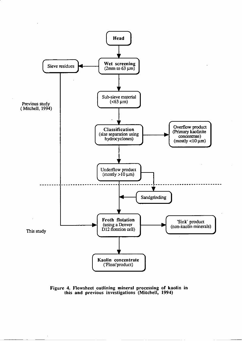
!lm material was dried and used for processing. The processing flow sheet linking techniques
used in the previous investigations and this study is shown in Figure 4.
Froth flotation was carried out to produce kaolinite concentrates (Appendix B). The flotation
was carried out in a pyrex cell using a Denver D12 Laboratory flotation machine. Deionised
water was used to prepare mineral suspensions. The pH was controlled with weak solutions of
sulphuric acid and sodium hydroxide. Excessive frothing during flotation was controlled with
heavy distillate (which partially neutralizes the effect of the surfactant). The collector used was
alkylamine (,Armoflote 13' from Akzo Nobel). This collector also acts as a frother. During
flotation kaolinite is floated away from the other minerals. Flotation was repeated several times
. in order to maximise the amount of separation. Prior to each repeated flotation the samples
were washed in hot water and detergent in order to remove reagent residues.
The proportions of kaolinite present in the processing products were determined by
thermogravimetry (TO) using a Stanton Redcroft 770 thermobalance. The weight losses of the
samples heated to 1000°C were recorded and interpreted as mineral percentages. The
mineralogy of the kaolinite concentrates was determined by X-ray diffraction (XRD). The
samples were loaded into· aluminium holders and scanned over the angular range 3 to 50° 28
using a Phillips PW 1700 X-ray diffractometer. The XRD traces were interpreted with
reference to the JCPDS dataset.
3.4. Results
3.4.1. Underflow products, Chilulwe kaolin
The froth flotation trials produced only a marginal increase in the kaolinite content of the
underflow products. The kaolinite content of the 30 mm underflow was increased from 64% to
71 % and the 1 inch underflow from 63 to 75%. No appreciable improvement in the grade of
the kaolin was produced by the sand-grinding trial (Table 3).
3.4.2. Sieve residues, Chilulwe kaolin
The froth flotation trials resulted in a modest increase in the kaolinite content of the sieve
residues. The kaolinite content of the 250 to 125 J.1m fraction was increased from 7% to 12%
and the 125 to 63 J.1m fraction from 20% to 26% (Table 3).
3.4. Discussion
The current investigation has shown that froth flotation can be used to separate kaolin from
other minerals. However, despite reasonable kaolinite recoveries (70 to 80%) the grades of the
kaolinite concentrates were low. Examination of these concentrates by XRD reveals that an
appreciable amount of feldspar and mica is still present. Also the middling and sink products
s~ have relatively high kaolinite contents. This indicates that the sand-grinding carried out in
this investigation was not aggressive enough to produce complete liberation of the kaolinite.
Future laboratory trials might focus on 'stirred media milling' of the wet processing residues.
This would involve the use of a silica sand with highly spherical grains, a suspension with a

low solids content and a high torque stirrer / attrition scrubber. This would hopefully liberate
the kaolinite present and enable the production of high-grade kaolinite concentrates by froth
flotation.
4. REFERENCES
Bloodworth, AJ, Highley, DE and Mitchell, CJ (1993) Kaolin - Industrial Minerals Laboratory
Manual. British Geological Survey, Tech. Rept WG/93/l.
Bloodworth, AJ (1994) Minerals for Development. British Geological Survey, Tech. Rept.
WG/94/13.
Crozier, RD (1990) Non-metallic mineral flotation. Industrial Minerals 269 pp.55-65.
Cyanamid (1989). Mining Chemicals Handbook. 184 pp.
ECC!. China clay production, Echo. 24 pp.
Harben, PW (1992) The Industrial Minerals Handybook. Metal Bulletin, p.29.
Klimpel, RR (1993) Froth flotation - an old process with a new outlook. Mining Magazine,
May, pp.266-276.
Mauser, RM (1975) Handbook of Silicate Flotation. Warren Spring Laboratory, pp.162-167.
Mitchell, CJ (1994) Laboratory evaluation of kaolin: A case study from Zambia. In Whateley
MKG & Harvey, PK (eds). Mineral Resource Evaluation II: Methods and Case
Histories, Geol. Soc. Spec. Pub. No. 79 pp. 241-247.
Mitchell, CJ and Henney, PJ (1994) Processing of Glensanda granite to produce glass-grade
feldspar. British Geological Survey MPSRl94/22C, 15 pp.
Mitchell, CJ and Evans, EJ (1995) Mineral procesing of granite fmes for Anglo Pacific
Resources Ltd. British Geological Survey, MPSRl95/65C, 11 pp.
Skillen, A (1993) Froth flotation. Industrial Minerals, 305, pp.47-59
Wills, BA (1992) Mineral Processing Technology. 5th edition. Pergamon Press. 855 pp.
5. BIBLIOGRAPHY
Akzo Nobel (1990). Mineral Processing Chemicals Handbook. 84 pp.
Finch, JA & Dobby, GS (1990) Column Flotation. Pergamon Press. 180 pp.
Gaudin, AM (1957) Flotation. McGraw-Hill. 573 pp.
Jones, MH & Woodcock, JT (eds.) (1984) Principles of Mineral Flotation. Australian IMM.
320 pp.
Sutherland, KL & Wark, IW (1955) Principles of Flotation. Australian IMM. 489 pp.
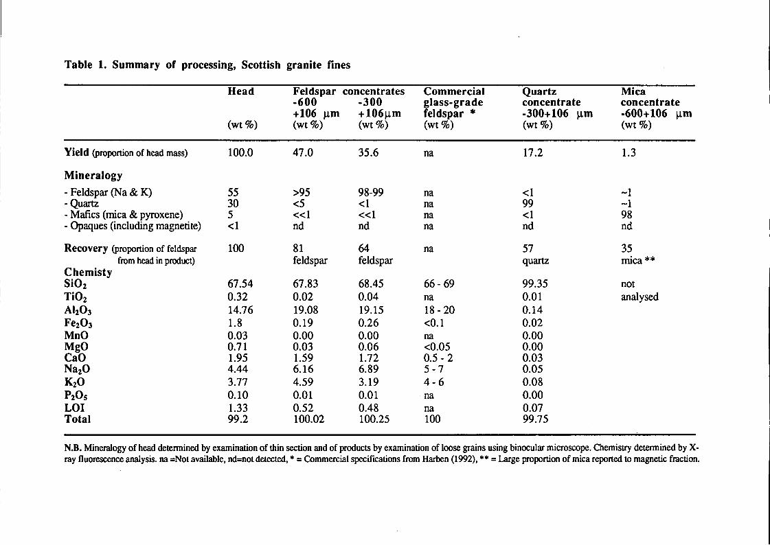
Table 1. Summary of processing, Scottish granite fines
Head Feldspar concentrates Commercial Quartz Mica -600 -300 glass-grade concentrate concentrate +106 )lm +106)lm feldspar * -300+106 )lm -600+106 )lm
(wt %) (wt%) (wt %) (wt%) (wt %) (wt %)
Yield (proportion of head mass) 100.0 47.0 35.6 na 17.2 1.3
Mineralogy
- Feldspar (Na & K) 55 >95 98-99 na <1 -1 - Quartz 30 <5 <1 na 99 -1 - Mafics (mica & pyroxene) 5 «1 «1 na <1 98 - Opaques (including magnetite) <1 nd nd na nd nd
Recovery (proportion of feldspar 100 81 64 na 57 35 from head in product) feldspar feldspar quartz mica **
Chemisty Si02 67.54 67.83 68.45 66 - 69 99.35 not Ti02 0.32 0.02 0.04 na 0.01 analysed AhOJ 14.76 19.08 19.15 18 - 20 0.14 Fe20J 1.8 0.19 0.26 <0.1 0.02 MnO 0.03 0.00 0.00 na 0.00 MgO 0.71 0.03 0.06 <0.05 0.00 CaO 1.95 1.59 1.72 0.5 - 2 0.03 Na20 4.44 6.16 6.89 5-7 0.05 K20 3.77 4.59 3.19 4-6 0.08 P20S 0.10 0.01 0.01 . na 0.00 LOI 1.33 0.52 0.48 na 0.07 Total 99.2 100.02 100.25 100 99.75
N.B. Mineralogy of head determined by examination of thin section and of products by examination of loose grains using binocular microscope. Chemistry determined by x-ray fluorescence analysis. na =Not available, nd=not detected, • = Commercial specifications from Harhen (1992), •• = Large proportion of mica reported to magnetic fraction.
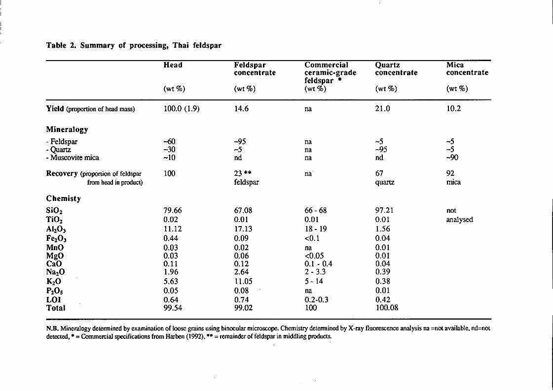
Table 2. Summary of processing, Thai feldspar
Head Feldspar Commercial Quartz Mica concentrate ceramic-grade concentrate concentrate
feldspar • (wt %) (wt%) (wt %) (wt %) (wt %)
Yield (proportion of head mass) 100.0 (1.9) 14.6 na 21.0 10.2
Mineralogy
- Feldspar -60 -95 na -5 -5 - Quartz -30 -5 na -95 -5 - Muscovite mica -10 nd na nd -90
Recovery (proportion of feldspar 100 23 *'Ie na 67 92 from head in product) feldspar quartz mica
Chemisty
Si02 79.66 67.08 66 - 68 97.21 not Ti02 0.02 0.01 0.01 0.01 analysed AI20 J 11.12 17.13 18 - 19 1.56 Fe203 0.44 0.09 <0.1 0.04 MnO 0.03 0.02 na 0.01 MgO 0.03 0.06 <0.05 0.01 CaO 0.11 0.12 0.1 - 0.4 0.04 Na20 1.96 2.64 2-3.3 0.39 K20 5.63 11.05 5 - 14 0.38 P20S 0.05 0.08 na 0.01 LOI 0.64 0.74 0.2-0.3 0.42 Total 99.54 99.02 100 100.08
N.B. Mineralogy detennined by examination of loose grains using binocular microscope. Chemistry detennined by X-ray fluorescence analysis na =not available, nd=not detected, • = Commercial specifications from Harben (l992), •• = remainder of feldspar in middling products.
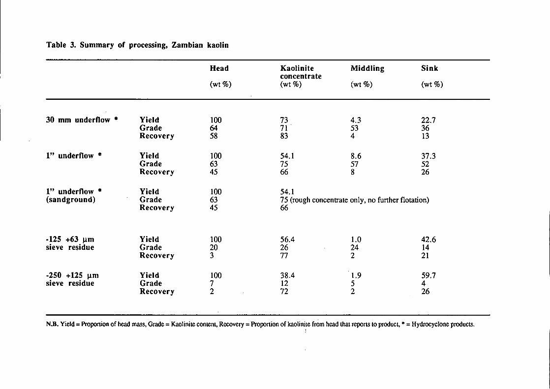
Table 3. Summary of processing, Zambian kaolin
Head
(wt%)
30 mm underflow * Yield 100 Grade 64 Recovery 58
I" underflow * Yield 100 Grade 63 Recovery 45
I" underflow * Yield 100 (sandground) Grade 63
Recovery 45
·125 +63 J.1m Yield 100 sieve residue Grade 20
Recovery 3
·250 +125 J.1m Yield 100 sieve residue Grade 7
Recovery 2
Kaolinite concentrate (wt %)
73 71 83
54.1 75 66
54.1
Middling
(wt %)
4.3 53 4
8.6 57 8
Sink
(wt %)
22.7 36 13
37.3 52 26
75 (rough concentrate only, no further flotation) 66
56.4 1.0 42.6 26 24 14 77 2 21
38.4 1.9 59.7 12 5 4 72 2 26
N.B. Yield = Proportion of head mass, Grade = Kaolinite content, Recovery = Proportion of kaolinite from head that reports to product, ... = Hydrocyclone products. , ,

· , , " t , , " t , , " t , , " t , , " t , , " t , , " t , , " t , , " t , , " t , , " t , , " t , , " t , , " t , , " t , , " t , ,
~o
e
0
N) '0'
~o ~
~
0 ~o
~O
0 0
Collection weir - mineral froth 'scooped' across to form 'float' product
/
Quiescent zone - allowing separation of mineral from
pulp and formation of stable froth
-- Agitated zone - forcing particles into suspension and forging
bubble:particle contact
Air bubble - stabilised by a surfactant (frother
reagent)
t" 0
" t , , t , , " t ,
" ,
o 0
o
~ o
o
o
o Target mineral surface rendered hydrophobic (by selective
coating with collector reagent) and therefore attractive to air
bubbles
o __ -J~----I--- Gangue mineral surface not affected by collector
o reagent and therefore drops to the bottom
forming a 'sink' product
Sink product (in reverse flotation this would represent the target mineral and the float product would be the gangue)
Figure 1. Cut-away diagram illustrating the theory of froth flotation

Granite fines «4 mm)
Crushing/grinding to <600 J.1.I11 & splitting
into sub-samples
" Grinding to I
<300 J.lm
Screening to remove <106
J.1.I11 material I-----~.. <106 J.lm ........ _-----1 .. fines ......
Screening to remove <106
J.1.I11 material
" Magnetic separation and froth flotation to
produce feldspar preconcentrate
Funher magnetic separation to produce feldspar concentrate
Magnetic fractions, quartz-rich and
mica-rich by-products
Magnetic separation and froth flotation to
produce feldspar preconcentrate
Funher froth flotation to produce feldspar
concentrate
Figure 2. Flowsheet outlining the mineral processing of the Scottish granite fines
Characterisation
I Head 1 ... Petrography (thin section) J ~ Mineralogy (XRD)
Chemistry (XRF)
~,
Sample preparation (~1 kg crushed to ~
Fines J liberation size & fines .. \ removed)
~,
Magnetic separation ... 1 Magnetic products (Carpco high-intensity ... l induced roll)
,r ( Non-magnetic product )
,Ir Froth notation ... Mica-concentrate &
First stage - remove mica .. mica-rich middling
" ( Quartz-feldspar rich product )
,r Froth notation ... Quartz-concentrate &
Second stage - remove quartz .. quartz-rich middling
" Feldspar concentrate
Figure 3. Flowsheet outlining mineral processing of feldspar (see Appendix A)
( Sieve residues }111~------1
Previous study ( Mitchell, 1994)
I Head
Wet screening (2mm to 63 ~)
Sub-sieve material «63 ~m)
• , IF
Classification (size separation using
hyclrocyclones)
" Underflow product (mostly> 10 ~m)
Overflow product ..... ___ ~.... (Primary kaolinite
.. concentrate) (mostly <10 ~m)
------- ------------------------ -------------- --------------------------
This study
... ..
" 14~1----f( Sandgrinding
Froth flotation (using a Denver
D12 flotation cell)
Kaolin concentrate ('Float'product)
.... 'Sink' product I------..~ (non-kaolin minerals)
Figure 4. Flowsheet outlining mineral processing of kaolin in this and previous investigations (Mitchell, 1994)
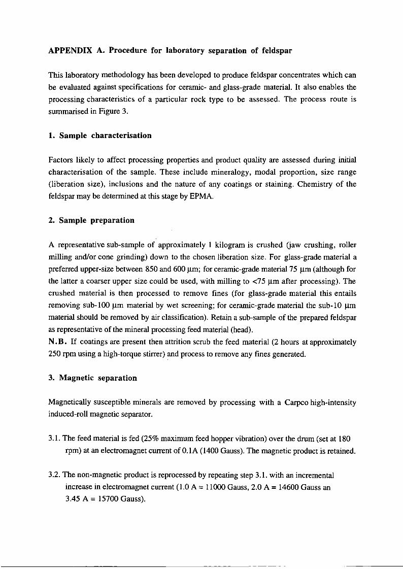
APPENDIX A. Procedure for laboratory separation of feldspar
This laboratory methodology has been developed to produce feldspar concentrates which can
be evaluated against specifications for ceramic- and glass-grade material. It also enables the
processing characteristics of a particular rock type to be assessed. The process route is
summarised in Figure 3.
1. Sample characterisation
Factors likely to affect processing properties and product quality are assessed during initial
characterisation of the sample. These include mineralogy, modal proportion, size range
(liberation size), inclusions and the nature of any coatings or staining. Chemistry of the
feldspar may be determined at this stage by EPMA.
2. Sample preparation
A representative sub-sample of approximately 1 kilogram is crushed (jaw crushing, roller
milling and/or cone grinding) down to the chosen liberation size. For glass-grade material a
preferred upper-size between 850 and 600 Jlm; for ceramic-grade material 75 Jlm (although for
the latter a coarser upper size could be used, with milling to <75 Jlm after processing). The
crushed material is then processed to remove fines (for glass-grade material this entails
removing sub-l00 Jlm material by wet screening; for ceramic-grade material the sub-l0 Jlm
material should be removed by air classification). Retain a sub-sample of the prepared feldspar
as representative of the mineral processing feed material (head).
N • B. If coatings are present then attrition scrub the feed material (2 hours at approximately
250 rpm using a high-torque stirrer) and process to remove any fmes generated.
3. Magnetic separation
Magnetically susceptible minerals are removed by processing with a Carpco high-intensity
induced-roll magnetic separator.
3.1. The feed material is fed (25% maximum feed hopper vibration) over the drum (set at 180
rpm) at an electromagnet current of O.IA (1400 Gauss). The magnetic product is retained.
3.2. The non-magnetic product is reprocessed by repeating step 3.1. with an incremental
increase in electromagnet current (1.0 A = 11000 Gauss, 2.0 A = 14600 Gauss an
3.45 A = 15700 Gauss).

3.3. The final non-magnetic product is used as the feed for froth flotation. A sub-sample is
retained as representative of the non-magnetic product.
4. Froth flotation
Mica and quartz are removed from the feldspar by two stage flotation using a Denver D12
Laboratory flotation machine. A maximum of 500 grams of sample should be used for any
single flotation trial. Ideally, the sample should be composed of particles between 100 and 300
11m in size (an upper limit of 500 J.l1I1 and a lower limit of 10 11m are achievable).
4.1. Mica removal
4.1.1. The feed material is placed into a glass cell with 1 litre of deionised water (ideally a
solids concentration of 50 to 60% is required). The pH is adjusted to 2.5 to 2.7 using
weak solutions of sulphuric acid and sodium hydroxide. Add approximately 20 drops of
alkylamine acetate (,Armoflote 64' from Akzo Nobel) as a collector. The mineral
suspension (pulp) is stirred (conditioned) for 4 minutes (the speed at which the pulp
should be stirred, and subsequently floated, depends on the particle size of the feed; 1000
to 1200 rpm for material <100 11m and 1200 to 1500 rpm for material >100 11m).
N.B. During conditioning the water level should be high enough to ensure that all of the
sample is in suspension. Ideally a solids content of 50 to 60% is required however it is
important that all grains are available for coating with collector reagent. Therefore more
deionised water should be added to ensure complete sample suspension.
4.1.2. Add more deionised water to the cell to bring the level of the pulp to approx. 1 to 2 cm
below the weir height (ideally this should be 20 to 30% solids concentration). Adjust the
pH to 3 to 3.3. Add 1 to 2 drops of methyl isobutyl carbinol (MIBC) as a frother.
4.1.3. Commence flotation by reducing the stirrer speed to 1000 rpm and introducing air into
the stirred pulp. Allow the froth to develop, this should be a stable layer of bubbles with a
'firm' looking appearance. (In some instances the bubbles will not be stable, bursting
upon contact with the air above. This is indicative of a lack of collector reagent. If this
occurs add more collector and recondition the pulp. At this stage it is not important to
readjust the pH back to 2.5 to 2.7, but it is important to adjust the pH to 3 to 3.3 prior to
flotation). Start collecting mineralised froth by scooping it across the weir (taking care not
to remove any of the pulp at the same time). Continue collecting froth until no more is
generated from the pulp. In extreme circumstances frothing may become excessive. If this
occurs add heavy distillate (1 drop) to the pulp to control the frothing. However this may
have the effect of eliminating any further flotation response, i.e. no more mica will float.
4.1.4. Add more collector (and more frother if required) and repeat conditioning/flotation.
4.1.5. Repeat step 4.1.4. until no more mineral is recovered from the froth (the pulp may
become murky/dark coloured).
4.1.6. Dewater the pulp (glass-grade material should be screened using a 63 JlIIl sieve; cerarnic
grade material should be dewatered using a Buchner funnel or a filter press). Wash the
sink material in hot water and detergent ('Teepol') to remove the flotation reagents.
Thoroughly wash the sink product using deionised water to remove detergent residues.
Removal of flotation reagents from the products may require repeated washing. However
washing is crucial as any residue of reagent remaining in the sample will adversely affect
further flotation response.
4.1.7. Repeat steps 4.1.1. to 4.1.6. until all the mica is removed from the sample. Thoroughly
wash all the float products in hot water and detergent prior to drying. Examine and
combine appropriate float products into a mica concentrate and a mica-rich middling.
4.1.8. The sink product is used as the feed material for the second stage of flotation (4.2.).
Retain a sub-sample of this as representative of the mica flotation sink product.
4.2. Quartz-feldspar separation
4.2.1. The flotation was carried out as for mica, with the following exceptions: The pH is
adjusted to 1.8 to 2.0. Add approximately 20 drops of fatty acid derivative:Butan-2-o1
(,Armoflote 543' from Akzo Nobel) as a collector. The pulp is conditioned for 4 minutes.
4.2.2. Add more deionised water to the cell to bring the level of the pulp to approx. 1 to 2 cm
below the weir height (ideally this should be 20 to 30% solids concentration). Add 1 to 2
drops of MIBC as a frother. N.B. No pH modification is required after conditioning.
4.2.3. Carry out steps 4.1.3 to 4.1.6. as for the mica removal procedure. The pH should not
be adjusted.
4.2.4. Repeat steps 4.2.1. to 4.2.3. until all the feldspar is removed from the sample.
Thoroughly wash all the float products in hot water and detergent prior to drying.
Examine and combine appropriate float products into a feldspar concentrate and a quartz
rich middling. The sink product is the quartz concentrate.
-------- - ----
5. Further processing
To remove any remaining impurities (such as feldspar with iron-bearing inclusions) further
processing may be considered, including high-intensity magnetic separation (wet or dry), froth
flotation (using reagents tailored to iron-bearing minerals) and chemical treatment (such as acid
leaching).
APPENDIX B. Procedure for the froth flotation of kaolin (Fig 4)
1. This procedure is designed to recover coarse kaolinite from hydrocyclone underflow
products and sieve residues from the wet processing of kaolin (Bloodworth et al., 1994).
Samples to be processed should ideally be composed of particles between 10 and 300 J.1m in
size. A maximum of 500 grams should be used per flotation trial.
2. The sample is placed into a glass cell with 1 litre of deionised water. The pH is adjusted to 2
to 3 (using weak solutions of sulphuric acid and sodium hydroxide). Add approximately 10
drops of alkylamine (,Armoflote 13' from Akzo Nobel) as a collector and condition for 4
minutes. The mineral suspension (pulp) is stirred (conditioned) for 4 minutes (using stirrer
speeds of 1000 to 1200 for material < 1 00 J.1m in particle size and 1200 to 1500 rpm for
material >100 mm in particle size). Through out conditioning the pH should be monitored and
maintained at the required range. N.B. During conditioning the water level should be high
enough to ensure that all of the sample is in suspension. Therefore more deionised water
should be added to ensure complete sample suspension.
3. Add more deionised water to the cell to bring the level of the pulp to approx. 1 to 2 cm
below the weir height. No frother is required.
4. Commence flotation by reducing the stirrer speed to 1000 rpm and introducing air into the
stirred pulp. Allow the froth to develop, this should be a stable layer of bubbles with a 'flrm'
looking appearance. (In some instances the bubbles will not be stable, bursting upon contact
with the air above. This is indicative of a lack of collector reagent. If this occurs add more
collector and recondition the pulp). Start collecting mineralised froth by scooping it across the
weir (taking care not to remove any of the pulp at the same time). Continue collecting froth
until no more is generated from the pulp. In extreme circumstances frothing may become
excessive. If this occurs add heavy distillate (1 drop) to the pulp to control the frothing.
However this may have the effect of eliminating any further flotation response, i.e. no more
kaolin will float.
5. Allow the pulp to settle and decant the clear supernatant. The sink product is dried and
weighed.
6. Dry the float product (retain a sub-sample for assay) and record its weigh. This is the
rougher concentrate and it is the feed for the second flotation stage.
7. Repeat steps 2 to 5. The sink product is known as the middling. The float product (flnal
kaolin concentrate) is dried and weighed.