british columbia specifications and guidelines for geomatics
TRANSCRIPT
British ColumbiaSpecifications and Guidelinesfor Geomatics
Content SeriesVolume 3
Digital Baseline Mapping at 1:20 000
Release 2.0January 1992
Ministry of Environment, Lands and ParksGeographic Data BCProvince of British Columbia
Copyright @ Ministry of Environment, Lands and ParksGeographic Data BCProvince of British Columbia
All rights reserved. No part of this document may be copied or reproduced without the prior written consent of the GeographicData BC, Ministry of Environment, Lands and Parks.
Canadian Cataloguing in Publication Data
Main Entry under title:British Columbia specifications and guidelines for geomatics. Content seriesVolume 3: Digital baseline mapping at 1:20 000.
ISBN 0-7718-9155-5
Digital mapping - Standards.Cartography - British Columbia. I. British Columbia. Geographic Data BC.

1
GA139.B74 1992 526'. 0285 C92-092063-2

2
Foreword
3
ForewordThis report is Volume 3 of a series of documents providing a content reference for the specification and transfer of geomatics data.In the broad field of geomatics, one of the main limiting factors to the wide use of Geographic Information Systems has been thelack of widely applicable data specifications. The current work and its companion volumes describe a set of specificationsappropriate for geomatics data management and data sharing.
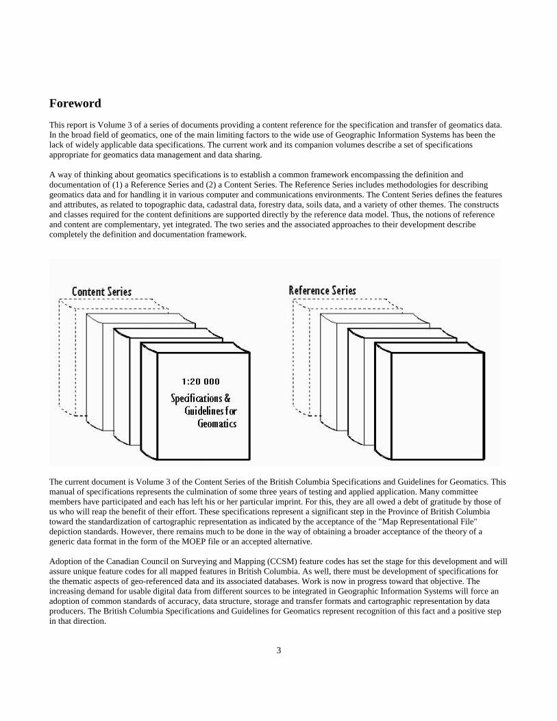
A way of thinking about geomatics specifications is to establish a common framework encompassing the definition anddocumentation of (1) a Reference Series and (2) a Content Series. The Reference Series includes methodologies for describinggeomatics data and for handling it in various computer and communications environments. The Content Series defines the featuresand attributes, as related to topographic data, cadastral data, forestry data, soils data, and a variety of other themes. The constructsand classes required for the content definitions are supported directly by the reference data model. Thus, the notions of referenceand content are complementary, yet integrated. The two series and the associated approaches to their development describecompletely the definition and documentation framework.
The current document is Volume 3 of the Content Series of the British Columbia Specifications and Guidelines for Geomatics. Thismanual of specifications represents the culmination of some three years of testing and applied application. Many committeemembers have participated and each has left his or her particular imprint. For this, they are all owed a debt of gratitude by those ofus who will reap the benefit of their effort. These specifications represent a significant step in the Province of British Columbiatoward the standardization of cartographic representation as indicated by the acceptance of the "Map Representational File"depiction standards. However, there remains much to be done in the way of obtaining a broader acceptance of the theory of ageneric data format in the form of the MOEP file or an accepted alternative.
Adoption of the Canadian Council on Surveying and Mapping (CCSM) feature codes has set the stage for this development and willassure unique feature codes for all mapped features in British Columbia. As well, there must be development of specifications forthe thematic aspects of geo-referenced data and its associated databases. Work is now in progress toward that objective. Theincreasing demand for usable digital data from different sources to be integrated in Geographic Information Systems will force anadoption of common standards of accuracy, data structure, storage and transfer formats and cartographic representation by dataproducers. The British Columbia Specifications and Guidelines for Geomatics represent recognition of this fact and a positive stepin that direction.

4

5
Introduction

6
IntroductionObjective
The Surveys and Resources mapping Branch of the Ministry of Environment and Parks is coordinating the development of aCorporate Land Information Strategic Plan for the government of British Columbia. The requirements of such a plan will include acommon digital map framework for the various land information retrieval systems. This will be provided by the Ministry ofEnvironment, Lands and Parks. The Geographic Data BC is currently developing a Provincial Digital Atlas based principally onthree distinct data sets at various scales; (1) 1:2 000 (one map covering the entire province), (2) 1:250 000 (84 map sheets coveringthe province), (3) the 1:20 000 TRIM product (7,000 map sheets for all of B.C.).
This volume relates directly to (3), the 1:20 000 product. In particular, these specifications relate to the generation of topographicdata at the scale of 1:20 000 (1:10 000/1:50 000 derived) in hard copy and digital form. Contractors, Provincial GovernmentMinistries and other agencies can obtain copies of these specifications from the Geographic Data BC, Ministry of Environment,Lands and Parks (Herein referred to as the Branch).
Format
This manual consists of four parts
Part I General SpecificationsPart II Detailed Geographic Object SpecificationsPart III Detailed Business Object SpecificationsPart IV Appendices

7
Table of Contents
FOREWORD ............................................................................................................................. 2
Foreword.................................................................................................................................................................................... 3
INTRODUCTION ....................................................................................................................... 5
Introduction............................................................................................................................................................................... 6Objective ................................................................................................................................................................................ 6Format.................................................................................................................................................................................... 6
PART I GENERAL SPECIFICATIONS.................................................................................... 10
Section 1 - System of Mapping ............................................................................................................................................... 111.1 British Columbia Geographic System ......................................................................................................... 11
Section 2 - Cartographic Framework.................................................................................................................................... 13
Section 3 - Digital Data Files .................................................................................................................................................. 143.1 General ........................................................................................................................................................... 143.2 Digital Data Format ...................................................................................................................................... 143.3 Positional Files ............................................................................................................................................... 143.4 Representational Files................................................................................................................................... 15
Section 4 – Data Accuracy...................................................................................................................................................... 164.1 Topographic Mapping .................................................................................................................................. 174.2 Graphical Data Accuracy ............................................................................................................................. 194.3 Published Map Accuracy.............................................................................................................................. 19
SECTION 5 DATA STRUCTURE............................................................................................ 21
Section 5 - Capture Rules for Specific Data Type ................................................................................................................ 225.1 Feature Types ................................................................................................................................................ 225.1.1 Point Features (Type 01)............................................................................................................................... 225.1.2 Line Features (Type 02 and Type 12) .......................................................................................................... 235.1.3 Curvilinear Features (Type 03 and Type 13) .............................................................................................. 245.1.4 Text Features (Type 06) ................................................................................................................................ 245.2 Digitizing Guidelines ..................................................................................................................................... 255.2.1 Right Hand Rule............................................................................................................................................ 255.2.2 Downstream Rule .......................................................................................................................................... 265.2.3 Continuity Rule ............................................................................................................................................. 275.2.4 Polygon Rule .................................................................................................................................................. 275.2.5 Connectivity and Network Rule ................................................................................................................... 285.2.6 Data Collection 3-D ....................................................................................................................................... 29
SECTION 6 DIGITAL ELEVATION MODELS......................................................................... 31
Section 6 - Digital Elevation Models ...................................................................................................................................... 32

8
6.1 DEM Definitions............................................................................................................................................ 326.2 DEM Specifications ....................................................................................................................................... 326.2.1 Gridded DEM Data Capture........................................................................................................................ 336.2.2 Random DEM Data Capture........................................................................................................................ 336.2.3 Supplimentary DEM Data Resolution......................................................................................................... 336.2.4 Data to be Excluded from DEM................................................................................................................... 336.2.5 Breakline Interpretation............................................................................................................................... 33
SECTION 7 TRANSFER FORMAT ......................................................................................... 34
Section 7 - Transfer File Format............................................................................................................................................ 357.1 Magnetic Tape Format .................................................................................................................................. 357.2 MOEP ASCII Format .................................................................................................................................... 367.2.1 ASCII Record Format.................................................................................................................................... 367.2.2 MOEP Feature Types .................................................................................................................................... 377.2.3 MOEP Feature Type Definition .................................................................................................................... 377.2.4 Sample MOEP ASCII Format File ............................................................................................................... 417.3 MOEP Binary Format ................................................................................................................................... 427.3.1 ASCII to Binary Comparison........................................................................................................................ 427.3.2 MOEP Binary Format Description............................................................................................................... 447.3.3 MOEP Binary Examples................................................................................................................................ 46
PART II DETAILED GEOGRAPHIC OBJECT SPECIFICATIONS ......................................... 49
Section 1 Feature Name / Feature Code Correlation ........................................................................................................... 501.1 Feature Class / Feature Code Listing by Class ............................................................................................ 511.2 Feature Code / Feature Name Index............................................................................................................. 611.3 Feature Name / Feature Code Index............................................................................................................. 68
SECTION 2 DETAILED GEOGRAPHIC OBJECT SPECIFICATIONS ................................... 76
SECTION 2 - DETAILED GEOGRAPHIC OBJECT SPECIFICATIONS ................................. 772.1 General Notes....................................................................................................................................................... 772.2 Instructions on Use of Detailed Specifications Tables...................................................................................... 782.3 Notes on Detailed Specifications......................................................................................................................... 792.3.1 Remarks - Aerial Triangulation and Related Features.............................................................................. 802.3.2 Remarks - Hydrographic and Related Features......................................................................................... 802.3.3 Remarks - Hypsographic, Landform, and Related Features..................................................................... 912.3.5 Remarks - Landmark and Related Features............................................................................................... 962.3.6 Remarks - Text Features ............................................................................................................................ 1002.3.7 Remarks - Transportation and Related Features..................................................................................... 1012.4 - Detailed Specifications.............................................................................................................................................. 103
PART III DETAILED BUSINESS OBJECT SPECIFICATIONS............................................. 246
PART IV APPENDICES ........................................................................................................ 248
Appendix A - Deliverables.................................................................................................................................................... 249A.1 Data Capture Deliverables ............................................................................................................................... 249

9
A.2 Cartographic Enhancement Deliverables ....................................................................................................... 249A.3 Edit Notations .................................................................................................................................................... 250A.4 Procedures for Marking Contractor Toponymy Submissions ...................................................................... 250A.5 General Deliverables ......................................................................................................................................... 251
Appendix B Representation File Editing Guidelines (Cartographic Enhancement)....................................................... 252
Appendix B - Cartographic Enhancement.......................................................................................................................... 253B.1 General ............................................................................................................................................................... 253B.2 Hierarchical Order for Feature Positioning ................................................................................................... 253B.3 Specific Editing Situations................................................................................................................................ 253B.4 Representational Hierarchy ............................................................................................................................. 253B.5 Basic Lettering Standards ................................................................................................................................ 254B.6 Guidelines Regarding Text Placement ............................................................................................................ 255
Appendix C Geographical Nomenclature (Toponymy) ..................................................................................................... 256
Appendix C - Geographical Nomenclature (Toponymy)................................................................................................... 257C.1 Range of Text Sizes to be Used (Toponymy)................................................................................................... 257C.2 Guidelines for Land Features........................................................................................................................... 260C.3 Guidelines for Nomenclature of Water Features............................................................................................ 261
Appendix D Surround Information..................................................................................................................................... 264
Appendix D - Surround Information................................................................................................................................... 265D.1 Cartographic Separations................................................................................................................................. 265D.2 Master Surround............................................................................................................................................... 265D.3 Legend ................................................................................................................................................................ 266
Appendix E Dictionary of Abbreviations............................................................................................................................ 267E.1 - Feature/Map Element Abbreviations ..................................................................................................................... 268
Appendix F IGDS Level/Colour Guidelines........................................................................................................................ 271
Appendix F – IGDS Level/Colour Guidelines..................................................................................................................... 272F.1 Feature Code - Feature Name - Level/Colour Correlation............................................................................ 272F.2 Feature Name - Feature Code - Level/Colour Correlation............................................................................ 281F.3 Level/Colour Correlation - Feature Name - Feature Code ........................................................................... 289
Appendix G Feature Name / Positional File Correlation................................................................................................... 296Appendix G - Feature Name / Positional File Correlation ............................................................................................ 297

10
Part I GENERAL SPECIFICATIONS

11
Section 1 - System of MappingAll mapping produced using these specifications for the Ministry of Lands conforms to the British Columbia Geographic System ofMapping (B.C.G.S) as defined in the Ministry of Environment publication entitled British Columbia Standards System of Mapping,1976 Edition.
1.1 British Columbia Geographic System
The British Columbia Geographic System is a geographic system in which the coverage in minutes and seconds of longitude isdouble the coverage in minutes and seconds of latitude for sheets at all scales. The smallest scale in the system is 1:20 000 derivedfrom a breakdown of the N.T.S. 1:250 000 sheet into 100 parts. Larger scales are obtained by successive quartering or furtherdivision into 100 parts. A map number consists of the appropriate N.T.S. 1:250 000 map number followed by the numbers of eachsuccessive breakdown, each separated by a period. See Table 1.1 and Figure 1.
Table 1.1
B.C.G.S. Scales, Map Numbers and Coverage
Scale Map Number Longitude Latitude1:20 000 82F.035 12' 6'1:10 000 82F.035.1 6' 3'

12
Figure 1
Note: Unless specified otherwise, all 1:10 000 scale mapping shall be derived from mapping compiled at 1:20 000 scale.

13
Section 2 - Cartographic Framework
All mapping is presented on the Universal Transverse Mercator Coordinate System (based on the 1983 North American Datum).The following points define more closely the map coverage as projected onto this datum.
a. The trimmed size of the sheet shall be 969 millimetres by 600 millimetres. The neat line shall be defined in Latitude by straight-line segments joining the geographic sheet corners and calculated at each six seconds of Longitude. The neat line shall be defined inLongitude by the straight line joining the geographic sheet corners.
b. For 1:500 scale mapping the neat line is defined in latitude by the straight-line segments joining the geographic sheet cornersand calculated at each three seconds of longitude. The neat line is defined in longitude by a straight line joining the geographic sheetcorners.
c. The plane reference grid will be the Universal Transverse Mercator Coordinate System depicted at ten centimetre intervals atmap scale. The datum used is the North American Datum defined in 1983 (NAD 83).
d. The vertical datum will be mean sea level as established by the Geodetic Survey of Canada.
e. For datasets that have a sheet boundary coincident with the 490 or 600 parallel, the 490 or 600 parallel is defined and labelled atthe corners but the sheet neatline is either the parallel or the surveyed B.C. boundary or a combination of both such that maximumarea is covered. The B.C. boundary is a surveyed line and is not always consistent with the line of latitude. The surveyed line isapparent at times north of the parallel, at times it will cross or be coincident with the parallel, and at other times it is evident south ofthe parallel.

14
Section 3 - Digital Data Files
3.1 General
a. The following data files will be available for each map sheet
Positional Files:
Data File 1 - Digital Elevation Model Data File 2 - Raw Contour File Data File 3 - Non-Positional Data File 4 - Planimetric Positional File Data File 5 - Toponymy File
Representational Files: Data File 1 -Planimetric Representational File (Section 3.4) Data File 2 -Contour Representational File (Section 3.4) Data File 3 - Master surround (Optional)
b. Digital planimetric raw contour data shall be "clipped" to the neat line as defined in Part I, Section 2a. Digital Elevation modeldata verification plot shall extend beyond the 1:20 000 map sheet neat line by 200 mtres.
c. All planimetric and elevation data shall be submitted in continuous 3-D form (i.e. easting, northing and elevation).
d. Digital data shall be feature coded according to the feratures given in section 3 (National Standards codes as adopted by theCCSM).
e. The positional toponymy file contains all toponymic information present in the planimetric representational file. NOTE: Thetoponymy file is extracted from the planimetric representational file and so is not available until representational file completion.
f. The master surround is the non-variable surround information as described in Appendix D. This file is available upon request.
3.2 Digital Data Format
The digital data files specified for the project shall be in the following formats:
Positional Files - Interchange format as per Part I, Section 7.
Representational File - Intergraph Design File (IGDS)
3.3 Positional Files
Each Positional file shall contain positionally correct, complete edited map data for one 1:20 000 map sheet. The data shall consistof all digital planimetric data compiled directly by stereo compilation. The digital data contained in the Positional files shall beaccording to those map features given in the detailed specifications in Part II of this manual, and shall be collected in accordancewith the guidelines set out in Appendix "B". No positional adjustments of data to eliminate conflicts shall be performed on this file.
All 1: 20 000 map sheet data files will be completed to the full map sheet boundary regardless of provincial, municipal or districtboundary conflicts, where the aerial triangulation and/or control survey permits.
15
Map data shall be edited as outlined in Part I Section 5 to the extent that all stereo model edge ties have been performed. Ties toadjacent map sheets have been performed. Linear features have connectivity and continuity, areal features have been explicitlyclosed, redundant data have been eliminated, and data have been coded according to the detailed specifications in Section 3.
Computer-assisted verification plots, produced from the Positional Files at a scale of 1:20 000, are required for each positional filesubmitted. (refer to Appendix "A")
The verification plots shall contain an identification title. Data which describes symbology or patterning construction elements usedto produce the hard copy plot should not be included in the Planimetric Positional File, it should be placed in a separate Non-Positional File.
Digital Elevation Models shall contain all DEM points collected directly by stereo compilation, breaklines (sharp and rounded), andsupplementary data indicated in Part II that has been filtered to the specifications outlined in Part I Section 6.2.3. This data willextend beyond the 1:20 000 neat line by 200 metres, as specified in Part I Section 3.1(b). The new contours generated from theDEM shall be a separate file on the tape containing the positional information.
Any changes made to the Positional Files as a result of quality control, e.g. missing data, incorrect coding, etc., must be correctedand the appropriate data file re-submitted in its corrected form.
3.4 Representational Files
Each Representational File shall contain cartographically correct, complete edited map data for one 1:20 000 map sheet.
All positional offsets (cartographic enhancement/generalization) of map data for the purposes of feature clarity or cartographicsymbolization shall be performed on this file, which initially shall be a copy of the Planimetric Positional File and the Raw ContourFile. Where offsets are required they shall abe made in accordance with the hierarchy described in Appendix "B".
These files shall be used to produce the final hard copy separations of the 1:20 000 base map as outlined in Appendix "D".

16
Section 4 – Data Accuracy
The accuracy requirements stated in these specifications will reflect those standards set under the North American TreatyOrganization (NATO) Standard Agreement (STANAG) for the evaluation of Land Maps.
The following information will provide a common understanding of the requirements and the statistical probabilities involved.
NATO accuracy standards are referenced to the Linear Map Accuracy Standard in Z and the Circular Map Accuracy Standard in X,Y at the ninety percent confidence intervals. In mapping there are two major types of distribution:
A. Univariate.B. Bivariate.
a. Univariate
The univariate case is one dimensional and in mapping refers to the Z value or elevation (height). It is referred to as the StandardError or the Mean Square Error in Height (MSEH).
Standard Error:
Standard Error =1.00σZ =68.27% probabilityLinear Map Accuracy Standard =1.64σZ =90.00% probabilityNear Certainty Error =3.00σZ =99.73% probability(Rejection level) =2.57σZ =99.00% probability
17
b. Bivariate
There are two methods of considering the bivariate case, those being the Mean Square Error (MSE) or Mean Square Error ofPosition (MSEP) and the Circular Standard Error (CSE).The MSE or MSEP can be unreliable in probability if the elipticity deviates significantly from a circle.
Mean Square Error (MSE) or Mean Square Error of Position (MSEP):
σXY = (σX2+ σY
2)1/2
Mean Square Error = 1.000σXY = 63.21% probabilityMean Square Error = 1.520σXY = 90.00% probabilityMean Square Error = 2.470σXY = 99.78% probability(Rejection level) = 2.140σXY = 99.00% probability
Circular Standard Error:σC = 0.7071(σX
2+ σY2)1/2
Circular Standard Error = 1.000σC = 39.35% probabilityCircular Map Accuracy Standard = 2.146σC = 90.00% probabilityCircular Near Certainty Error = 3.500σC = 99.78% probability(Rejection level) = 3.035σC = 99.00% probability
4.1 Topographic Mapping
4.1.1 Photogrammetric Instrument Accuracy
The instrument to be used in stereo compilation shall be of sufficient accuracy to produce data conforming to the accuracies statedbelow.
An instrument manufacturer's written calibration report recent to within 1 year shall be available for inspection prior to compilationand shall be prepared annually.
The optical-mechanical train of all instruments shall be tested for accuracy immediately prior to project compilation and every threemonths during project compilation. These reports shall be submitted, as required by the Branch.
4.1.2 Absolute Orientation Accuracy
The stereo models will be physically oriented by the operator prior to data capture. The orientation will be absolute. This will allowthe operator to read true values in the model and thus better interpret the model.
Earth curvature and atmospheric refraction correction will be applied where applicable.

18
Scaling:
At least six (6) ground/photogrammetric control points located at the Von Gruber points of the model shall be positioned such thatall control points fit to within 4 metres of the adjusted coordinates. Control points not meeting this specification shall be "flagged"on model set-up records and brought to the attention of the Client.
Leveling:
At least six (6) ground/photogrammetric control points located at the Von Gruber points of the model shall be levelled such that allcontrol points fit to within 4 metres. Control points not meeting this specification shall be "flagged" on model set-up records andbrought to the attention of the Client.
4.1.3 Map Positional File Accuracy
a. Ninety percent of all well defined planimetric features shall be coordinated to within 10 metres (0.5mm x 20,000) of their trueposition. This corresponds to the following:
Bivariate:
CMAS = 2.146σC ≤ 10.00 metres (90.00%)CSE = 1.000σC ≤ 4.66 metres (39.35%)MSEP = 1.000σXY ≤ 6.60 metres (63.21%)MSEP = 1.520σXY ≤ 10.03 metres (90.00%)
Rejection (blunders):
MSEP = 2.47σXY ≤ 16.31 metres (99.78%)CMAS = 3.5σC ≤ 16.31 metres (99.78%)
b. Ninety percent of all discrete spot elevations and DEM points shall be accurate towithin 5 metres of their true elevation. This corresponds to the following:
Univariate:
LMAS = 1.640σZ ≤ 5.00 metres (90%) probabilityLSE = 1.000σZ ≤ 3.00 metres (68.27%) probabilityNOTE: Linear Standard Error ≤ Mean Standard Error in Height LSE = MSEH
Rejection (blunders):Univariate = 3.0σZ ≤ 9.00 metres (99.73%) probability
c. Ninety percent of all points interpolated from the DEM (including contour data) shall be accurate to within 10 meters of theirtrue elevation. This corresponds to the following:
Univariate:
LMAS = 1.64σZ ≤ 10.00 metres (90%) probabilityLSE = 1.00σZ ≤ 6.10 metres (68.27%) probability
Rejection (blunder):Univariate = 3.0σZ ≤ 18.30 metres (99.73%) probability
19
d. True position/elevation is defined as the coordinates, which would be obtained from positioning with high order groundmethods.
e. Accuracies relating to elevations refer to ground not sufficiently obscured by vegetation or other features to cause significanterror.
4.2 Graphical Data AccuracyHard copy, computer generated graphical products shall be produced on equipment meeting or exceeding the followingspecifications:
Positional File | Map Representational File PlotVerification Plot | (Cartographic Separations)Accuracy + 1.5 mm | + 0.15 mm
The plotter used to produce the final cartographic separations (refer to Part IV, Appendix "D") shall have sufficient resolution (i.e.step size) to ensure that all map features (including text) are fair drawn in accordance with good cartographic practice.
Accuracy of the plotter shall be measured by checking map grids. Grids shall be checked with reference to a standard grid whichhas been plotted to a + 0.1mm tolerance. A best fit of check grid and plotted grid shall be achieved and discrepancies at gridintersections evaluated.
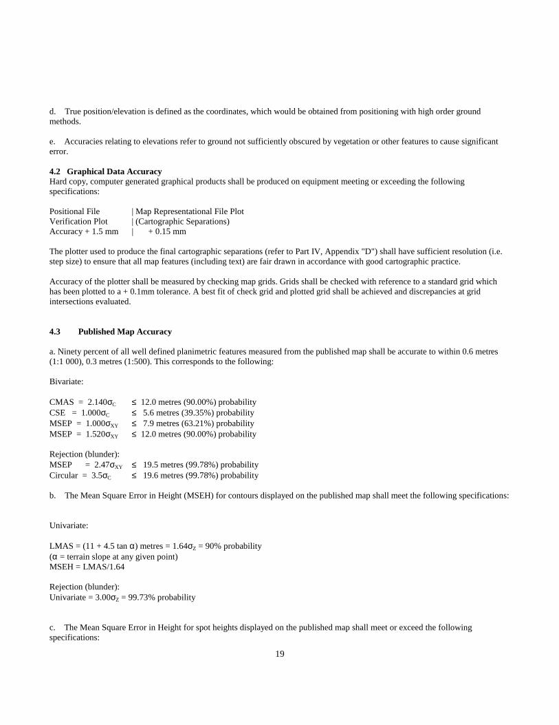
4.3 Published Map Accuracy
a. Ninety percent of all well defined planimetric features measured from the published map shall be accurate to within 0.6 metres(1:1 000), 0.3 metres (1:500). This corresponds to the following:
Bivariate:
CMAS = 2.140σC ≤ 12.0 metres (90.00%) probabilityCSE = 1.000σC ≤ 5.6 metres (39.35%) probabilityMSEP = 1.000σXY ≤ 7.9 metres (63.21%) probabilityMSEP = 1.520σXY ≤ 12.0 metres (90.00%) probability
Rejection (blunder):MSEP = 2.47σXY ≤ 19.5 metres (99.78%) probabilityCircular = 3.5σC ≤ 19.6 metres (99.78%) probability
b. The Mean Square Error in Height (MSEH) for contours displayed on the published map shall meet the following specifications:
Univariate:
LMAS = (11 + 4.5 tan α) metres = 1.64σZ = 90% probability(α = terrain slope at any given point)MSEH = LMAS/1.64
Rejection (blunder):Univariate = 3.00σZ = 99.73% probability
c. The Mean Square Error in Height for spot heights displayed on the published map shall meet or exceed the followingspecifications:

20
Spot Heights:LMAS = (5.5 + 4.5 tan α) metres = 1.64σZ = 90% probability(α = terrain slope at any given point)MSEH = LMAS/1.64
Rejection (blunder):Linear = 3.00σZ = 99.73% probability
d. The above accuracies are relative to the true position of the features as definedby the coordinates which would be obtained from positioning with higher orderground methods.
e. Relief stated in "b" and "c" above relate to ground not sufficiently obscured byvegetation or other features to cause significant error.

21
Section 5 Data Structure

22
Section 5 - Capture Rules for Specific Data Type
5.1 Feature Types
5.1.1 Point Features (Type 01)

23
5.1.2 Line Features (Type 02 and Type 12)
Each point on the feature defines an exact beginning or end point, or a point of deflection and the line joining the points defines thetrue position of the feature being plotted (within project accuracies).
When features are collinear, the features having lesser hierarchical order will be coded as a construction line (Type 12). They canthen be eliminated in the Representational file.

24
5.1.3 Curvilinear Features (Type 03 and Type 13)
Each point lies on the feature, however, the line joining the points may or may not define the true position of the features beingplotted, depending on the scale used to depict the feature. The number of points on the feature will be such as to cartographicallyrepresent it at 1:1 000/1:500 with a minimum of three points.
This type of line may be Asmoothed@ by interpolating a curve through the data points.
When features are collinear, the features having lesser hierarchical order will be coded as a curvilinear construction line (Type 13).They can thus be eliminated in the Representational file.
All curvilinear line strings (Type 03) features when clipped on sheet edges must contain three or more unique points or be changedto line (Type 02) feature.
5.1.4 Text Features (Type 06)

25
5.2 Digitizing Guidelines
5.2.1 Right Hand Rule
Feature boundaries will be digitized such that the feature being bounded is kept to the right hand side relative to the forward motionof the stereoplotter floating mark.
NOTE: Right Hand Rule is superseded by the Downstream Rule for double<196>sided Hydrographic features.

26
5.2.2 Downstream Rule
Hydrographic features having a gradient will be digitized in a downstream direction.
NOTE: Right Hand Rule is superseded by the Downstream Rule for double-sided hydrographic features.

27
5.2.3 Continuity Rule
Hydrographic features will not be broken for other feature groups; i.e. rivers will be digitized continuously across roads, throughdams, etc.
5.2.4 Polygon Rule
All areal features such as wooded areas, built<196>up areas, designated areas, reservoirs, etc. will be explicitly closed polygonalareas, with Right Hand or Downstream rules applied, except where an areal feature meets the map sheet boundary. Exactduplication of data will be done to close all polygonal features, and these duplicated line segments will be represented as eithervisible or non-visible as per Appendix B ARepresentational Hierarchy@.
e.g. Reservoirs will be completed along dams.

28
5.2.5 Connectivity and Network Rule
All lines of like and unlike feature groups, which intersect or close on themselves will do so at numerically and mathematicallyexact coordinated junction points or nodes. These nodes divide continuous features into discrete elements which begin and end atnodes.
All features which intersect planimetrically (X,Y) but not vertically (Z), will do so at numerically exact X,Y coordinate positions,but will not connect numerically in Z.
Wooded areas, cutlines, and seismic lines are exempt from the normal 0.25 and 0.12 metre vertical accuracy requirement. Thesefeatures must be snapped to other intersecting features at ground elevation (x,y,z) (1 metre vertical accuracy).
NOTE: An X, Y or Z jog is acceptable, provided the 0.5 metre planimetric, and 0.25 metre Z accuracy standards (tree line excepted)are met, and the jog is not noticeable at published map scale. (See below)
x point on riverο point on treeline• Start point of treeline with coordinates lying on line connecting points A and B on river
The line connecting N1, N2, N3 and N6 is a continuous feature which has been broken into 3 discrete, separately identifiableelements between the nodes N1-N2, N2-N3, N3-N6. (This may be done interactively or in batch mode.)

29
5.2.6 Data Collection 3-D
a) Features that intersect in 3 dimensions will have an x,y,z node. Features that intersect in x,y but do not intersect vertically willbe captured with a x,y node.
b) Linear planimetric positional data will be captured to create consistent data sets. The sampling will conform to the followingresolution at map scale:
delta x of 0.35 millimetres, delta y of 0.35 millimetres, delta z of 0.25 millimetres
Linear planimetric positional data may be filtered to the following resolution:
delta x of 1.25 millimetres, delta y of 1.25 millimetres, delta z of 0.5 millimetres

30
Provided the resulting filtered line does not deviate from the sampled line by more than 0.05 metres.
c) The following linear planimetric positional features may be exempt from the above spacing requirements when they can berepresented by straight lines that comply with positional accuracy and cartographic representation requirements.
AerialCableway Airfield AirPort / Airstrip (Abandoned)Airport AmmunitionDump AutoWreckerBarn Breakwater BridgeBuilding Builtup Area CableCampGround/Campsite Cemetery ChurchCityHall College Contour(all types)Conveyor Courthouse CustomsOfficeCutlineSeismicLine Dam(all types) DEMPoint.type"Check"DesignatedArea DriveinTheatre DrivingRangeDryDock DumpElectricalSubstationComplex ExhibitionGrounds FallsFence FerryDock FerryRouteFerryTerminal FireStation FishHatcheryFlume FootBridge GolfCourseGreenHouse Hospital LibraryLumberYard MarinaYachtClub MilitaryEstablishmentNursery Orchard Park/PicnicAreaPenitentiary PhotoCentre Pier/WharfPipeline PoliceStation PostOfficeRaceTrack RailLine(all types) RapidsRoad(all types) School ScreeSewageTreatmentArea SkiJump SkiLiftSnowshed SportsField SportTrackStockYard Tank TollGateTransmissionLine(all types) TrailerPark TrestleTunnel University VineyardWoodedArea Yard Zoo
NOTE:These exemptions refer to point spacing requirements only. They are not exemptions to the accuracy requirements.

31
Section 6 Digital Elevation Models

32
Section 6 - Digital Elevation Models
6.1 DEM Definitions
In order that communication of ideologies and concepts pertaining to Digital Elevation Models (DEM) is clearly understood, thefollowing will serve as a list of definitions:
DEM - A DEM is a file of points captured specifically to represent the topographic surface shape in explicit Z values and X,Yvalues. It is composed of a series of spot elevations read using either a gridded or random method.
It also contains other supplementary vertical information. This supplementary data will take the form of data digitized forplanimetric detail representation which is of a suitable accuracy for the DEM, break lines both sharp and rounded and spotelevations. The DEM is the basis for the mathematical representation of the surface.
Supplementary DEM Data - These are data, which have been digitized for planimetric representation of detail and are also used inthe DEM. These data can take the form of streams, railways, roads and other features as detailed in Part II. These data will befiltered, to the specified density for inclusion in the DEM. All points in the DEM file will carry a DEM feature code.
Break lines extracted from the planimetric file will have a DEM feature code which will indicate the source of the breakline eg.Transportation, Hydrographic, Hypsographic. (See Part II).
Break line - A breakline is a natural or man made occurrence in the topography where there is a definite and obvious change incontour direction. There is a definite change in deflection along a breakline, and elevations are captured along its entirety. Anexample would be a stream or a vertical bluff.
I. Sharp Breakline: A sharp breakline causes a definite pointed character to the interpolated contour.
ii. Rounded Breakline: A rounded breakline causes a smoother but still well defined deflection to the contour.
Areas of Indefinite Contours - These are areas which are outlined in the DEM in such a manner that contours which are interpolatedwithin its boundary will be depicted as indefinite. They may be explicitly digitized or defined by copying actual feature outlines.
Indefinite Contours - These contours are coded where the ground cannot be accurately interpreted, i.e. glaciers, icefields, shadowsareas and stereo dead zones (DEM spacing may be increased to 200 metres if necessary).Areas of Exclusion - These are areas, which are outlined in the DEM in such a manner that contours will not be interpolated withinthe enclosing polygon. Examples would be man made features such as dam faces or active pits. They may be explicitly digitized ordefined by copying actual feature outlines.
6.2 DEM Specifications
The DEM data in the file will extend ten millimetres (map scale) beyond the sheet corners. This will provide for proper contourinterpolation on the sheet boundary. Data will be common to the adjacent sheet.
In order that the DEM data be of a sufficiently dense nature to meet the vertical accuracy requirements, and generate interpolatedcontours with character representative of the terrain, the data capture specifications for DEM in gridded or random method will befollowed. All point to point linear features captured as stream digitized that are included in DEM must meet specifications.
33
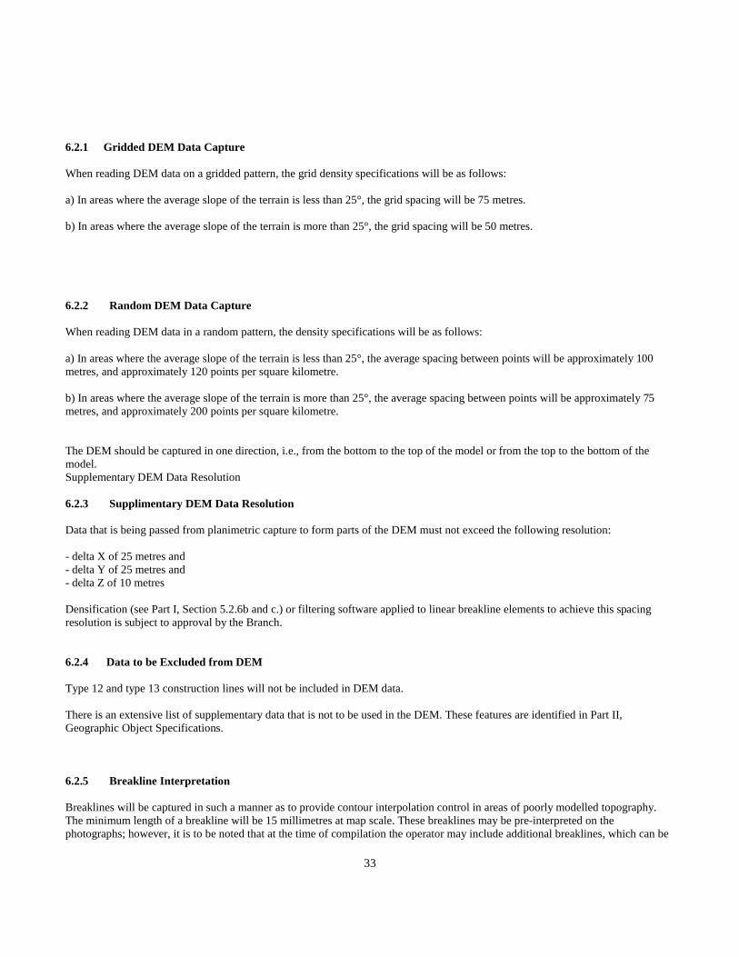
6.2.1 Gridded DEM Data Capture
When reading DEM data on a gridded pattern, the grid density specifications will be as follows:
a) In areas where the average slope of the terrain is less than 25°, the grid spacing will be 75 metres.
b) In areas where the average slope of the terrain is more than 25°, the grid spacing will be 50 metres.
6.2.2 Random DEM Data Capture
When reading DEM data in a random pattern, the density specifications will be as follows:
a) In areas where the average slope of the terrain is less than 25°, the average spacing between points will be approximately 100metres, and approximately 120 points per square kilometre.
b) In areas where the average slope of the terrain is more than 25°, the average spacing between points will be approximately 75metres, and approximately 200 points per square kilometre.
The DEM should be captured in one direction, i.e., from the bottom to the top of the model or from the top to the bottom of themodel.Supplementary DEM Data Resolution
6.2.3 Supplimentary DEM Data Resolution
Data that is being passed from planimetric capture to form parts of the DEM must not exceed the following resolution:
- delta X of 25 metres and- delta Y of 25 metres and- delta Z of 10 metres
Densification (see Part I, Section 5.2.6b and c.) or filtering software applied to linear breakline elements to achieve this spacingresolution is subject to approval by the Branch.
6.2.4 Data to be Excluded from DEM
Type 12 and type 13 construction lines will not be included in DEM data.
There is an extensive list of supplementary data that is not to be used in the DEM. These features are identified in Part II,Geographic Object Specifications.
6.2.5 Breakline Interpretation
Breaklines will be captured in such a manner as to provide contour interpolation control in areas of poorly modelled topography.The minimum length of a breakline will be 15 millimetres at map scale. These breaklines may be pre-interpreted on thephotographs; however, it is to be noted that at the time of compilation the operator may include additional breaklines, which can be

34
more easily interpreted in the stereo model. The operator may also capture breaklines of less than the minimum length where thefeature is of landmark importance, such as in a land slide area.
Section 7 Transfer Format

35
Section 7 - Transfer File Format
MOEP is now the format in use by the Branch. Users of this manual may wish to use different data formats based on their softwareand hardware. This will not affect data integration between GIS users as long as data is captured according to this specification. Allpositional data must be supplied in the following format:
7.1 Magnetic Tape Format
1. Half inch (1/2) wide industry standard magnetic tape;
2. 2400 foot reels;
3. 9 track recording;
4. 1600 bpi density;
5. No standard labelling;
6. MOEP format data must consist of ASCII characters only;
7. Each block will consist of 50 records, 80 characters in length, for a total of 4,000 characters of data. The last block may beshorter as required.
8. Each tape will be clearly labelled as to density, content, source, and numbers of records in each file.
SHEET: 000P.000 SUBMISSION: 1FORMAT: MOEPFILE TYPE: PositionalFile 1 - DEMFile 2 - ContoursFile 3 – Non-Positional DataFile 4 - PlanimetricCONTRACTOR: DATE: 92-00-00
Band label should read:
SHEET: 000P.000 SUBMISSION:FORMAT: MOEP FILE TYPE: PositionalCONTRACTOR: DATE: 92-00-00
36
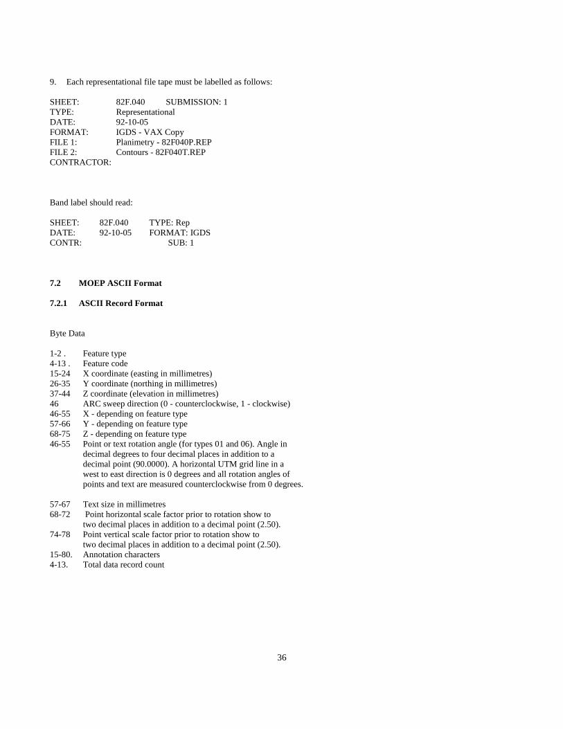
9. Each representational file tape must be labelled as follows:
SHEET: 82F.040 SUBMISSION: 1TYPE: RepresentationalDATE: 92-10-05FORMAT: IGDS - VAX CopyFILE 1: Planimetry - 82F040P.REPFILE 2: Contours - 82F040T.REPCONTRACTOR:
Band label should read:
SHEET: 82F.040 TYPE: RepDATE: 92-10-05 FORMAT: IGDSCONTR: SUB: 1
7.2 MOEP ASCII Format
7.2.1 ASCII Record Format
Byte Data
1-2 . Feature type4-13 . Feature code15-24 X coordinate (easting in millimetres)26-35 Y coordinate (northing in millimetres)37-44 Z coordinate (elevation in millimetres)46 ARC sweep direction (0 - counterclockwise, 1 - clockwise)46-55 X - depending on feature type57-66 Y - depending on feature type68-75 Z - depending on feature type46-55 Point or text rotation angle (for types 01 and 06). Angle in
decimal degrees to four decimal places in addition to adecimal point (90.0000). A horizontal UTM grid line in awest to east direction is 0 degrees and all rotation angles ofpoints and text are measured counterclockwise from 0 degrees.
57-67 Text size in millimetres68-72 Point horizontal scale factor prior to rotation show to
two decimal places in addition to a decimal point (2.50).74-78 Point vertical scale factor prior to rotation show to
two decimal places in addition to a decimal point (2.50).15-80. Annotation characters4-13. Total data record count
37
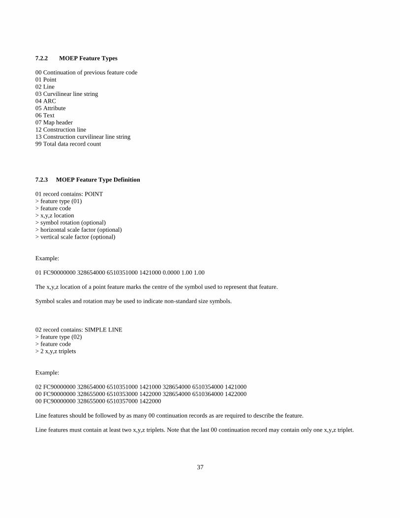
7.2.2 MOEP Feature Types
00 Continuation of previous feature code01 Point02 Line03 Curvilinear line string04 ARC05 Attribute06 Text07 Map header12 Construction line13 Construction curvilinear line string99 Total data record count
7.2.3 MOEP Feature Type Definition
01 record contains: POINT> feature type (01)> feature code> x,y,z location> symbol rotation (optional)> horizontal scale factor (optional)> vertical scale factor (optional)
Example:
01 FC90000000 328654000 6510351000 1421000 0.0000 1.00 1.00
The x,y,z location of a point feature marks the centre of the symbol used to represent that feature.
Symbol scales and rotation may be used to indicate non-standard size symbols.
02 record contains: SIMPLE LINE> feature type (02)> feature code> 2 x,y,z triplets
Example:
02 FC90000000 328654000 6510351000 1421000 328654000 6510354000 142100000 FC90000000 328655000 6510353000 1422000 328654000 6510364000 142200000 FC90000000 328655000 6510357000 1422000
Line features should be followed by as many 00 continuation records as are required to describe the feature.
Line features must contain at least two x,y,z triplets. Note that the last 00 continuation record may contain only one x,y,z triplet.

38
03 record contains: COMPLEX LINE> feature type (03)> feature code> 2 x,y,z triplets
Example:
03 FC90000000 328654000 6510351000 1421000 328654000 6510354000 142100000 FC90000000 328655000 6510353000 1422000 328654000 6510364000 142200000 FC90000000 328655000 6510357000 1422000
Curvilinear features should be followed by as many 00 continuation records as are required to describe the feature. Curvilinearfeatures must contain at least three x,y,z triplets. Note that the last 00 continuation record may contain only one x,y,z triplet.
04 record contains: ARC
Line 1> feature type (04)> feature code> x, y, z ARC start location> x, y, z ARC end location
Line 2> feature type (00)> feature code> x, y, z, ARC origin> ARC sweep direction (0 - counterclockwise, 1 - clockwise)
Example:
04 FC90000000 328654000 6510351000 1421000 328654000 6510354000 142100000 FC90000000 328655000 6510353000 1422000 0
05 record contains: ATTRIBUTE> feature type (05)> feature code> attribute - maximum 66 characters
Example:
05 FC90000000 Attribute
Attribute features appear as the first record preceding every planimetric feature. They may contain such information as watershedcodes and tower heights or be blank. Attribute data will begin at byte position 15 and be left justified. DEM points, contours andtext do not require an 05 (attribute) record.
06 record contains: TEXT> feature type (06)> feature code> x,y,z location> text rotation angle

39
> size of annotation in millimetres at ground scale
The x,y,z triplet denotes the bottom left corner of the first character of the text string. The 06 record is followed by one or more 00records containing the annotation characters. Toponymic text elements require a preceding type 05 attribute record. This recordcontains the font, weight, and unique group number (for text strings that require more than one origin).
The type 05 element is organized as follows:
Byte Data
1-2 feature type4-13 feature code15-17 font number19-20 weight value22-26 unique text group identifier
Example:
05 FC90000000 31 2 210006 FC90000000 328654000 6510351000 1421000 0.0000 10000000 FC90000000 Text Sting
07 record contains: MAP HEADER> feature type (07)> file type - byte position 4 contains a 1 character code specifying file type. 1. DEM, 2. RAW contours,> 3. Non- Positional, 4. Planimetric Positional> map name - byte positions 15-44 contain a 1:1000 BCGS map sheet number (i.e. 82F.035.45.1) left justified> submission date year month day (numeric) (921005) byte positions 45-50.
Example:
07 4 94K.071.45.1 900812
12 record contains: CONSTRUCTION SIMPLE LINE> feature type (12)> feature code> 2 x,y,z triplets
Example:
12 FC90000000 328654000 6510351000 1421000 328654000 6510354000 142100000 FC90000000 328655000 6510353000 1422000 328654000 6510364000 142200000 FC90000000 328655000 6510357000 1422000
Identifies lines that are duplicates. Lines must contain two or more x,y,z triplets.
Note this data is not to be included in the DEM Data Set.
13 record contains: CONSTRUCTION COMPLEX LINE

40
> feature type (13)> feature code> 2 x,y,z triplets
Example:
13 FC90000000 328654000 6510351000 1421000 328654000 6510354000 142100000 FC90000000 328655000 6510353000 1422000 328654000 6510364000 142200000 FC90000000 328655000 6510357000 1422000
Identifies splines that are duplicates. Splines must contain three or more x,y,z triplets.
Note this data is not to be included in the DEM Data Set.99 record contains:> feature type (99)> total data record count
Example:
99 67890
This value is the total data record count excluding itself.

41
7.2.4 Sample MOEP ASCII Format File
42
7.3 MOEP Binary Format
7.3.1 ASCII to Binary Comparison
a) Type 07 Header
In the MOEP ASCII format the first record of every file is a type 07 record containing the file type, map sheet number, andsubmission date plus enough blanks to pad out to 80 characters.
This is replaced in the compressed format by the first 26 bytes of the file. These bytes contain the file type, map sheet number, thesubmission date, and the x and y offsets.
b) Feature Coordinates
In the MOEP ASCII format every feature is described by one or more sets of x,y,z coordinates. The x and y coordinates are UTMvalues that can be precise to the nearest millimetre. Similarly the z value is a height above sea level with possible millimetreprecision. Submissions under the 1:250 000 and 1:20 000 mapping programs supply all coordinates to the nearest metre whichconforms to published accuracy requirements. This results in all feature coordinates having three trailing zeroes that are a constantfor all 1:20 000 and 1:250 000 scale topographic submissions and so are eliminated from the compressed version.
Feature x and y grid values are stored in the MOEP ASCII format as UTM coordinates. To reduce the grid value size, allcoordinates are redefined to a new grid with the 0,0 point at the centre of the map sheet. Map sheet centre coordinates can becalculated for 1:500 000, 1:250 000, 1:100 000, 1:50 000, 1:20 000, 1:10 000, 1:5 000, 1:2 500, 1:1 000 and 1:500 map sheets. Forscales at 1:50 000 and larger, the new coordinates are stored as two byte integers. For scales smaller than 1:50 000, four byteintegers are used to represent the x and y coordinates. Elevations are stored as two byte integers in all cases.
i.e. For the map sheet 82F.050, the UTM coordinates at the centre of the map sheet are E 565233 N 5477871. If the first feature islocated at UTM coordinates 570273000 5474622000 z-1645000 the redefined coordinates for this feature would be -5040 32491645.
c) Feature Code
Feature codes are currently stored as the second field of every feature. The compressed format would store a feature code only oncefor a feature and only if the feature code was different than that of the previous feature.
i.e. If ten river features occur in sequence then the feature code GA 24850 000 is stored only for the first feature.
d) Type 05 Attribute
Currently most features carry a type 05 attribute record. This record is most often blank but even when it contains data it is paddedout to the full 80 characters. In the compressed format, the attribute data is truncated and the number of attribute characters is savedfollowed by the characters themselves. If no type 05 is present for the feature then the number of characters is set to -1.
i.e. If a type 05 contains a tower height 55 plus 54 blanks, the compressed format would contain the number of characters (2) andthe tower height.
e) Scale and Rotation Factors
The ASCII format contains scale and rotation values for all point and text features. In the compressed format these values are storedas integers only if they are not 1.0 for the scaling factors and 0.0 for the rotation factor.

43
i.e. If a point symbol feature contains the vertical and horizontal scale factors 1.50 2.00 and a rotation value of 45.0000, thecompressed feature stores them as 150 200 and 450000.
f) Continuation Records
In line features the 00 continuation type is not maintained in the compressed format. A byte count takes their place as the first oneor two bytes preceding the coordinate list. (see i)iv) below)
g) Text Records
In the compressed format the text record is truncated and preceded by a character count. This eliminated the storage of paddedblanks. Note that in the compressed format a maximum of 66 characters of annotation are stored.
h) Field Separators
In the ASCII format blanks are required to separate all fields for legibility. In the binary format these blanks are not required and soare eliminated.
i) Feature Type
The compressed format carries a much more descriptive feature type. This feature type describes the following:a) What type of feature is it? (point, line, or text)b) Is a feature code present or is this feature the same code as the preceding one?
c) If this is a linear feature is it planimetric data or contour data?d) If this is a linear feature how many coordinates are present?e) If this is a point or text feature is a rotation stored, are scaling factors stored, are both scale and rotation stored, or are neitherpresent?
j) Type 99
The MOEP ASCII file contains as the last record a total data record count. This is eliminated in the compressed format. The finalbyte in the compressed format is a -1 to signal the end of file.
44
7.3.2 MOEP Binary Format Description
VAX Environment - Fixed length unformatted 512 byte records Each compressed record contains several MOEP compressedfeatures. Note that features will cross record boundaries.
The first 26 bytes of the file contain header information as follows:
byte 1 - file type (1-DEM, 2-contour, 4-plan, 5-Cadastre).
this byte value is increased by 100 if the map scale is smaller then 1:50 000 to indicate that an I*4 coordinate system has been used.
- bytes 2-12 - BCGS/NTS map number (ASCII).
- bytes 13-18 - submission date (ASCII year month day - e.g 921005).
- Bytes 19-22 - I*4 Easting offset (UTM centre of map sheet).
- bytes 23-26 - I*4 Northing offset (UTM centre of map sheet).
The first byte of a feature is the feature key.
Range 1-146
100's range 0-1- 0 - feature code is the same as the last feature code and so is not stored. <%0>
- 1 - feature code is different than the last feature code and so is<R>stored in the next ten bytes.
10's range 0-4
- 0 - no coordinate byte count, rotation, or scale stored
- 1 - a one byte coordinate count is stored if line, a rotation only is stored if point or text
- 2 - a two byte coordinate count is stored if line, scale only is stored if point
- 3 - a one byte coordinate count is stored (contour data) scale and rotation is stored if point
- 4 - a two byte coordinate count is stored (contour data)
1's range 1-7
1 - feature type 01 (point)2 - feature type 02 (line)3 - feature type 03 (line)4 - feature type 12 (line)5 - feature type 13 (line)6 - feature type 06 (text)7 - feature type 04 (arc)

45
The feature code if present fills the next 10 bytes.
The next byte either following the feature key or following the feature code if present is the type 05 key.
range -1 - 66
- 1 - no feature type 05 present
- 0-66 - number of feature type 05 bytes to follow
The next one or two bytes either following the type 05 key or following the type 05 bytes if present is the number of featurecoordinates to follow. If the feature is a type 01 (point), type 06 (text), or type 04 (arc) then this byte is not present.
The next bytes are the feature coordinates. If the feature is a point or text then a single x,y,z triplet is represented by 6 bytes (x-I*2,y-I*2, z-I*2) for scales larger than 1:50 000 or 10 bytes (x-I*4, y-I*4, z-I*2) for scales smaller than 1:50 000. If the feature is an arcthen three x,y,z triplets are used to represent the start, end, and origin of the arc. These triplets take up 18 bytes for scales of 1:50000 or larger or 30 bytes for scales smaller than 1:50 000. If the feature is a line type then the number of bytes is one of thefollowing.
for scales 1:50 000 and larger (x-I*2, y-I*2, z-I*2)
- non-contour data - number of coordinates times 6- contour data - 2 bytes z value plus number of coordinates times 4
for scales smaller than 1:50 000 (x-I*4, y-I*4, z-I*2)
- non-contour data - number of coordinates times 10- contour data - 2 bytes z value plus number of coordinates times 8
Line feature - complete
Arc feature - next byte contains the sweep direction indicator -- 0 - counterclockwise- 1 - clockwise
Point feature - next 4 bytes contain rotation angle if not 0.0 - I*4- next 4 bytes contain horizontal and vertical scale factors if not 1.0 - 2 I*2
Text feature - next 4 bytes contain rotation angle if not 0.0 - I*4- next 2 bytes contain text size in metres I*2- next byte contains number of text characters - maximum 66- next bytes contain text data
The last byte of the file is a -1 to signal the end of file.
46
7.3.3 MOEP Binary Examples
NOTE - The following examples use 570000 and 5470000 as offsets
1 - Point feature with type 05, scale factors and rotation present, and feature code different than the previous feature
MOEP ASCII format
05 HA90100000 ATTRIBUTE01 HA90100000 570273000 5474622000 1645000 5.6100 5.00 1.75
Compressed format (fields separated for clarity)131 HA90100000 9 ATTRIBUTE 273 4622 1645 56100 500 175
2 - Point feature with a blank type 05, default scale factors and rotation, and a feature code the same as the previous feature
MOEP ASCII format
05 HA9010000001 HA90100000 570273000 5474622000 1645000 0.0000 1.00 1.00
Compressed format (fields separated for clarity)1 0 273 4622 1645
3 - Text feature with type 05 attribute, rotation present, and a feature code different than the last feature.
MOEP ASCII format05 KC90000000 Text Feature06 KC90000000 570273000 5474622000 1645000 5.6100 50000000 KC90000000 Annotation
Compressed format (fields separated for clarity)116 KC90000000 12 Text Feature 273 4622 1645 56100 500 10 Annotation
4 - Text feature with blank type 05, no rotation present, and a feature code the same as the last feature.
MOEP ASCII format
05 KC90000000
06 KC90000000 570273000 5474622000 1645000 0.0000 50000000 KC90000000 Annotation
Compressed format (fields separated for clarity)6 0 273 4622 1645 500 10 Annotation
5 - Linear planimetric feature with 9 points, a type 05 attribute, and a feature code different than the last feature.
47
MOEP ASCII format
05 GA94850000 ATTRIBUTE02 GA94850000 570273000 5474622000 1645000 570373000 5473622000 154500000 GA94850000 570473000 5472622000 1625000 570573000 5471622000 152500000 GA94850000 570673000 5470622000 1605000 570773000 5469622000 150500000 GA94850000 570873000 5468622000 1585000 570973000 5467622000 148500000 GA94850000 571073000 5466622000 1565000
Compressed format (fields separated for clarity)112 GA94850000 9 ATTRIBUTE 9 273 4622 1645 373 3622 1545 473 2622 1625 573 1622 1525 673 622 1605 773 -378 1505873 -1378 1585 973 -2378 1485 1073 -3378 1565
6 - Linear planimetric feature with 9 points, no type 05 attribute, and a feature code not different than the last feature.
MOEP ASCII format
12 GA94850000 570273000 5474622000 1645000 570373000 5473622000 154500000 GA94850000 570473000 5472622000 1625000 570573000 5471622000 152500000 GA94850000 570673000 5470622000 1605000 570773000 5469622000 150500000 GA94850000 570873000 5468622000 1585000 570973000 5467622000 148500000 GA94850000 571073000 5466622000 1565000
Compressed format (fields separated for clarity)14 -1 9 273 4622 1645 373 3622 1545 473 2622 1625 573 1622 1525 673 622 1605 773 -378 1505 873 -1378 1585 973 -2378 14851073 -3378 1565
7 - Linear contour feature with 9 points, a type 05 attribute, and a feature code different than the last feature.
MOEP ASCII format
5 HA90001000 ATTRIBUTE3 HA90001000 570273000 5474622000 1600000 570373000 5473622000 160000000 HA90001000 570473000 5472622000 1600000 570573000 5471622000 160000000 HA90001000 570673000 5470622000 1600000 570773000 5469622000 160000000 HA90001000 570873000 5468622000 1600000 570973000 5467622000 160000000 HA90001000 571073000 5466622000 1600000
Compressed format (fields separated for clarity)133 HA90001000 9 ATTRIBUTE 9 1600 273 4622 373 3622 473 2622 573 1622 673 622 773 -378 873 -1378 973 -2378 1073 -3378
8 - Linear contour feature with 9 points, no type 05 attribute, and a feature code not different than the last feature.
MOEP ASCII format
13 HA90001000 570273000 5474622000 1600000 570373000 5473622000 160000000 HA90001000 570473000 5472622000 1600000 570573000 5471622000 160000000 HA90001000 570673000 5470622000 1600000 570773000 5469622000 160000000 HA90001000 570873000 5468622000 1600000 570973000 5467622000 160000000 HA90001000 571073000 5466622000 1600000
Compressed format (fields separated for clarity)

48
35 -1 9 1600 273 4622 373 3622 473 2622 573 1622 673 622 773 -378 873 -1378 973 -2378 1073 -3378
9 - Sample MOEP ASCII file - 2720 bytes
07 1 TESTFILE 92042305 HA90100000 ATTRIBUTE01 HA90100000 570273000 5474622000 1645000 5.6100 5.00 1.7505 HA9010000001 HA90100000 570273000 5474622000 1645000 0.0000 1.00 1.0005 KC90000000 Text Feature06 KC90000000 570273000 5474622000 1645000 5.6100 50000000 KC90000000 Annotation05 KC9000000006 KC90000000 570273000 5474622000 1645000 0.0000 50000000 KC90000000 Annotation05 GA94850000 ATTRIBUTE02 GA94850000 570273000 5474622000 1645000 570373000 5473622000 154500000 GA94850000 570473000 5472622000 1625000 570573000 5471622000 152500000 GA94850000 570673000 5470622000 1605000 570773000 5469622000 150500000 GA94850000 570873000 5468622000 1585000 570973000 5467622000 148500000 GA94850000 571073000 5466622000 156500012 GA94850000 570273000 5474622000 1645000 570373000 5473622000 154500000 GA94850000 570473000 5472622000 1625000 570573000 5471622000 152500000 GA94850000 570673000 5470622000 1605000 570773000 5469622000 150500000 GA94850000 570873000 5468622000 1585000 570973000 5467622000 148500000 GA94850000 571073000 5466622000 156500005 HA90001000 ATTRIBUTE03 HA90001000 570273000 5474622000 1600000 570373000 5473622000 160000000 HA90001000 570473000 5472622000 1600000 570573000 5471622000 160000000 HA90001000 570673000 5470622000 1600000 570773000 5469622000 160000000 HA90001000 570873000 5468622000 1600000 570973000 5467622000 160000000 HA90001000 571073000 5466622000 160000013 HA90001000 570273000 5474622000 1600000 570373000 5473622000 160000000 HA90001000 570473000 5472622000 1600000 570573000 5471622000 160000000 HA90001000 570673000 5470622000 1600000 570773000 5469622000 160000000 HA90001000 570873000 5468622000 1600000 570973000 5467622000 160000000 HA90001000 571073000 5466622000 160000099 33
Sample Compressed MOEP file (fields separated for clarity) - 367 bytes
1 TESTFILE 920423 570000 5470000 131 HA90100000 9 ATTRIBUTE 273 4622 1645 56100 500 175 1 0 273 4622 1645 116KC90000000 12 Text Feature 273 4622 1645 56100 500 10 Annotation 6 0 273 4622 1645 500 10 Annotation 112 GA94850000 9ATTRIBUTE 9 273 4622 1645 373 3622 1545 473 2622 1625 573 1622 1525 673 622 1605 773 -378 1505 873 -1378 1585 973 -2378 1485 1073 -3378 1565 14 -1 9 273 4622 1645 373 3622 1545 473 2622 1625 573 1622 1525 673 622 1605 773 -378 1505 873-1378 1585 973 -2378 1485 1073 -3378 1565 133 HA90001000 9 ATTRIBUTE 9 1600 273 4622 373 3622 473 2622 573 1622 673622 773 -378 873 -1378 973 -2378 1073 -3378 35 -1 9 1600 273 4622 373 3622 473 2622 573 1622 673 622 773 -378 873 -1378973 -2378 1073 -3378 -1

49
Part II Detailed Geographic Object Specifications

50
Section 1 Feature Name / Feature Code Correlation

51
Section 1 - Feature Name / Feature Code Correlation
1.1 Feature Class / Feature Code Listing by Class
Although numerous combinations of feature class and attribute are possible, only a subset of those combinations are relevant to thescale and discipline of the data specified in this document. This section provides the user with a feature name and code listing of therelevant combinations by class.

52
Aerial Triangulation Feature Class CadastralPoint.status"PermanentlyMarked" (symbol) FD90500000 ControlPoint.type"Vertical".status"PermanentlyMarked" (symbol) FB18650000
ControlPoint.type"Horizontal".status"PermanentlyMarked" (symbol) FB18450000Photo Centre FD21100000

53
Hydrographic Feature Class Coastline Geometric Rep Qualifier: Definite GG05800000 Coastline Geometric Rep Qualifier: Indefinite GG95800130
Hydro Structure Breakwater (to scale) GE03050110
(symbolized) GE03050120 Dam
Beaver (to scale) GA08450110
Dam.section"Base" GA98450100 Dam.section"Spillway/Penstock" (to scale) GA28550000 Dam.section"Top" (to scale) GA08450000
(symbol) GA98450000 Dyke GE09400000 Falls (to scale) GA10450000 Falls (symbol) GA90002110
Island Geometric Rep Qualifier: Position Approximate GE94850100 Island (to scale) GE14850000 Island Geometric Rep Qualifier:Definite (symbol) GE94850000
Rapids (to scale) GA23500000 Rapids (symbol) GA23500110 Sand/GravelBar (area outline) GE25850000 Sand/GravelBar (area symbol) GE90100000 SeaWall GE26250000
Water Body
FloodedLand.type"Inundated" (area outline) GB11350110 FloodedLand.type"Inundated" (area symbol) GB90000000
IceMass Glacier GD12300000IceField GD14450000
Lake Geometric Rep Qualifier: Definite GB15300000 Lake Geometric Rep Qualifier: Indefinite GB15300130 Lake.type"Intermittent" GB15300140 Marsh (area outline) GC17100000 Marsh (area symbol) GC90100000
Reservoir Geometric Rep Qualifier: Definite GB24300000 Reservoir Geometric Rep Qualifier: Indefinite GB90100000
Reservoir.type"Intermittent" GB90100110 Reservoir.type"ProposedMaxResLevel" GB90100120 Swamp (area outline) GC30050000 Swamp (area symbol) GC90200000 Water Course Arrowhead (symbol) GE90200110 Canal GA03950000 Canal.type"LeftBank" GA90001110 Canal.type"RightBank" GA90001120 Ditch GA08800110 Flume GA11500000 River/Stream Geometric Rep Qualifier: Definite GA24850000 River/Stream Geometric Rep Qualifier: Indefinite GA24850140 River/Stream.type"Dry" GA24850130

54
River/Stream.type"Intermittent" GA24850150 River/Stream.type"LeftBank" GA90000110 River/Stream.type"RightBank" GA90000120
Sinkhole HB27550000 Spring (symbol) GF28750000
Hypsographic Feature PhotoCentre (symbol) FD21100000
AreaofExclusion HC90000000 AreaofIndefiniteContours HC90000100 BreakLine.type"Hydrographic" HA90200130 BreakLine.type"Hypsographic" HA90200120 BreakLine.type"Round" HA90200110 BreakLine.type"Sharp" HA90200000 BreakLine.type"TransportationandOtherManMade" HA90200140
Contour.type"Index" HA90000000 Contour.type"Index".option"Depression" HA90000130 Contour.type"Index".option"DepressionIndefinite" HA90000140 Contour.type"Index".option"Indefinite" HA90000110 Contour.type"Intermediate" HA90001000 Contour.type"Intermediate".option"Depression" HA90001130 Contour.type"Intermediate".option"DepressionIndefinite" HA90001140 Contour.type"Intermediate".option"Indefinite" HA90001110
DEMPoint.type"Definite" (symbol) HA90100000 DEMPoint.type"Check" (symbol) HA90400000 DEMPoint.type"Indefinite" (symbol) HA90100110 DEMPoint.type"Interpolated" (symbol) HA90300000 MountainPeak HB18800000 SpotHeight (symbol) HA28700000 WaterLevel(DateofPhotography) (symbol) HA33100000
Land Cover Feature Class
Nursery JB19150000 Orchard JB19650000 Vineyard JB32800000 WoodedArea JA33750000

55
Land Form Feature Class
CliffScarp HB05650000 Esker HB10200000 ForeshoreFlats (area symbol) GE90850100 LavaBed HB15850000 Moraine HB18700000 Scree HB26150000 Slide (area outline) HB27900000 Slide (area symbol) HB90000000 VolcanicCrater HB07650130

56
Land Mark Feature Class
Beacon (symbol) CQ01850000Building BR90000000 Building (symbol) BR90000110 Barn BA01450000 Church (to scale) BM05300000 (symbolized) BM91100000 CityHall (to scale) BF05550000 CityHall (symbolized) BF91200000 College (to scale) BE90800000 College (symbolized) BE05900000 CommunicationsBuilding (symbol) BC29250000 Courthouse (to scale) BF07550000 Courthouse (symbolized) BF91300000 CustomsOffice (to scale) BF01850000 CustomsOffice (symbolized) BF90100000 FireStation (to scale) BF11000000 FireStation (symbolized) BF90200000 Greenhouse (to scale) BA12800000 Greenhouse (symbol) BA90100000 Hospital (to scale) BH13950000 Hospital (symbol) BH90300000 Library (to scale) BE16200000 Library (symbol) BE90700000 Lighthouse (symbol) CQ16350100 Penitentiary (to scale) BF20950000 Penitentiary (symbol) BF90400000 PoliceStation (to scale) BF22000000 PoliceStation (symbol) BF90500000 PostOffice (to scale) BF22250000 PostOffice (symbol) BF90600000 School (to scale) BE26000000 School (symbol) BE90900000 Silo (symbol) BA90000110 University (to scale) BE32400000 University (symbol) BE91000000
BuiltupArea AR03400000 Burner (symbol) CG03550000 Cable EA03800000 Conveyor CQ06400000
57
Designated Area AS90000000 AmmunitionDump AJ00650000 AutoWrecker AB33850110 CampgroundCampsite AL03900000 Cemetery AM04560000 DriveinTheatre AL09000000 DrivingRange AL23300120 Dump AP09200000 ElectricalSubstationComplex AG09850000 ExhibitionGrounds AL10250000 FishHatchery AF11150000 GolfCourse AL12350000 LumberYard AB33850140 MilitaryEstablishment AJ01650000 Mine AG17750000 Mine.type"OpenPit" AG17600000 Park/PicnicArea AL20150000 Pit.type"Abandoned" AG21550001 Pit.type"GravelSand" AG21550000 RaceTrack AL22650000 RifleRange AL23300140 SettlingPond EA26700100 SewageTreatmentArea AP26750000 SportTrack AL22650110 SportsField AL21900000 StockYard AB33850150 TailingArea AP30300000 TailingPond AP90300100 TrailerPark AN31950000 Yard AB33850000 Zoo AL33900000DryDock CG09100000Fence CR10750000FerryDock CQ08850130FerryTerminal(to scale) BQ30750140FerryTerminal(symbolized) BQ90750140FireLookoutTower BF10950120GasWell CG12150000Marina / Dock CQ08850160OilWell CG19600000Pier/Wharf(to scale CQ21250000Pier/Wharf (symbolized) CQ90000120Pile AG21275000Pipeline EA21400000Quarry GB22500000SkiJump CL27750000SkiLift CL27800000SmokestackChimney CG28300000Tank (to scale) EA30400000 (symbolized) EA90000000TollGate (to scale) DD31000000 (symbolized) DD91000000Tower.type"Microwave" CC31150110Tower.type"Transmission" CC90000000Tower.type"Unspecified" CC31150000TransmissionLine EA16400120WeighScale (to scale) CG33250000

58
(symbolized) CG33250100
Text Feature Class AerialTriangulation KC90000000 Generic KC91000000 Hydrographic KB14250000 HypsographicContourNumbers KC14300130 HypsographicExcludingContourNumbers KC14300000 LandCover KC14300310 LandForm KC90500000 Landmark KC90200000 Toponymy KC90300000 Transportation KC90100000
Transportation Feature Class
Air Feature AirField AQ00450000 Airport AQ00500000 Airstrip AQ00550000 Helipad AQ13451000 AirFeature.type”Abandoned” AirField/Airstrip AQ00550001 CutlineSeismicLine JA08400000 FerryRoute AQ10800000 HighwayID.type"Numbers" UNDEFINED HighwayID.type"SymbolCircle" UNDEFINED HighwayID.type"SymbolOval" UNDEFINED
Rail Feature RailLine.type"AbandonedTrack" DE22950001 RailLine.type"DoubleTrack" DE22850000 RailLine.type"MultipleTrack" DE22900000 RailLine.type"SingleTrack" DE22950000 RailLine.type"Spur" DF28850000 Turntable DD32300000 Road.surface"Loose".lanes"1".type"Undivided" DA25000110 Road.surface"Loose".lanes"1".type"Undivided".status"U/C" DA25000160 Road.surface"Loose".lanes"2".type"Undivided" DA25000120 Road.surface"Loose".lanes"2".type"Undivided".status"U/C" DA25000170 Road.surface"Paved".lanes"1".type"Undivided" DA25100180 Road.surface"Paved".lanes"1".type"Undivided".status"U/C" DA25100320 Road.surface"Paved".lanes"2".type"Divided" DA25050180 Road.surface"Paved".lanes"2".type"Divided".status"U/C' DA25050310 Road.surface"Paved".lanes"2".lanedir"OneWay" DA25100190 Road.surface"Paved".lanes"2".lanedir"OneWay".status"U/C" DA25100330 Road.surface"Paved".lanes"3".type"Undivided" DA25100200 Road.surface"Paved".lanes"3".type"Undivided".status"U/C" DA25100340 Road.surface"Paved".lanes"4".type"Divided" DA25050190 Road.surface"Paved".lanes"4".type"Divided.status"U/C" DA25050320 Road.surface"Paved".lanes"4".type"Undivided" DA25100210 Road.surface"Paved".lanes"4".type"Undivided".status"U/C" DA25100350 Road.surface"Paved".lanes"6".type"Divided" DA25050200 Road.surface"Paved".lanes"6".type"Divided".status"U/C" DA25050330 Road.surface"Paved".lanes"6".type"Undivided" DA25100220

59
Road.surface"Paved".lanes"6".type"Undivided".status"U/C" DA25100360 Road.surface"Rough" DA25150000

60
Transportation Structure AerialCableway CQ00300000 Bridge DD93250000 CutEarthwork DD08350000 FillEmbankment DD09950000 FootBridge DD93100000 Snowshed DD28350000 Trestle DD93200000 Tunnel DD93220000 Trail DD31700000

61
1.2 Feature Code / Feature Name Index
This section provides the data user with a listing of feature names and their correlated feature codes sorted alphabetically by featurecode.

62
Feature Code Feature Name
AAB33850000 YardAB33850110 AutoWreckerAB33850140 LumberYardAB33850150 StockYardAF11150000 FishHatcheryAG09850000 ElectricalSubstationComplexAG17600000 Mine.type"OpenPit"AG17750000 MineAG21275000 PileAG21550000 Pit.type"GravelSand"AG21550001 Pit.type"Abandoned"AJ00650000 AmmunitionDumpAJ01650000 MilitaryEstablishmentAL03900000 CampgroundCampsiteAL09000000 DriveinTheatreAL10250000 ExhibitionGroundsAL12350000 GolfCourseAL20150000 Park/PicnicAreaAL21900000 SportsFieldAL22650000 RaceTrackAL22650110 SportTrackAL23300120 DrivingRangeAL33900000 ZooAM04560000 CemeteryAN31950000 TrailerParkAP09200000 DumpAP26750000 SewageTreatmentAreaAP30300000 TailingAreaAP90300100 TailingPondAQ00450000 AirFieldAQ00500000 AirportAQ00550000 AirstripAQ00550001 Airport.status"Abandoned"AQ10800000 FerryRouteAQ13450000 HelipadAR03400000 BiultupAreaAS90000000 DesignatedArea
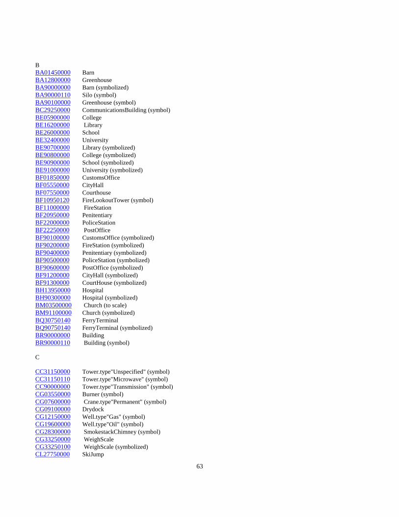
63
BBA01450000 BarnBA12800000 GreenhouseBA90000000 Barn (symbolized)BA90000110 Silo (symbol)BA90100000 Greenhouse (symbol)BC29250000 CommunicationsBuilding (symbol)BE05900000 CollegeBE16200000 LibraryBE26000000 SchoolBE32400000 UniversityBE90700000 Library (symbolized)BE90800000 College (symbolized)BE90900000 School (symbolized)BE91000000 University (symbolized)BF01850000 CustomsOfficeBF05550000 CityHallBF07550000 CourthouseBF10950120 FireLookoutTower (symbol)BF11000000 FireStationBF20950000 PenitentiaryBF22000000 PoliceStationBF22250000 PostOfficeBF90100000 CustomsOffice (symbolized)BF90200000 FireStation (symbolized)BF90400000 Penitentiary (symbolized)BF90500000 PoliceStation (symbolized)BF90600000 PostOffice (symbolized)BF91200000 CityHall (symbolized)BF91300000 CourtHouse (symbolized)BH13950000 HospitalBH90300000 Hospital (symbolized)BM03500000 Church (to scale)BM91100000 Church (symbolized)BQ30750140 FerryTerminalBQ90750140 FerryTerminal (symbolized)BR90000000 BuildingBR90000110 Building (symbol)
C
CC31150000 Tower.type"Unspecified" (symbol)CC31150110 Tower.type"Microwave" (symbol)CC90000000 Tower.type"Transmission" (symbol)CG03550000 Burner (symbol)CG07600000 Crane.type"Permanent" (symbol)CG09100000 DrydockCG12150000 Well.type"Gas" (symbol)CG19600000 Well.type"Oil" (symbol)CG28300000 SmokestackChimney (symbol)CG33250000 WeighScaleCG33250100 WeighScale (symbolized)CL27750000 SkiJump

64
CL27800000 SkiLiftCQ00300000 AerialCablewayCQ01850000 Beacon (symbol)CQ06400000 ConveyorCQ08850130 FerryDockCQ08850160 Dock/MarinaCQ16350000 Lighthouse (symbolized)CQ21250000 Pier/Wharf (to scale)CQ90000120 Pier/Wharf (symbolized)CR10750000 Fence
D
DA25000110 Road.surface"Loose".lanes"1".type"Undivided"DA25000120 Road.surface"Loose".lanes"2".type"Undivided"DA25000160 Road.surface"Loose".lanes"1".type"Undivided".status"U/C"DA25000170 Road.surface"Loose".lanes"2".type"Undivided".status"U/C"DA25050180 Road.surface"Paved".lanes"2".type"Divided"DA25050190 Road.surface"Paved".lanes"4".type"Divided"DA25050200 Road.surface"Paved".lanes"6".type"Divided"DA25050310 Road.surface"Paved".lanes"2".type"Divided".status"U/C'DA25050320 Road.surface"Paved".lanes"4".type"Divided.status"U/C"DA25050330 Road.surface"Paved".lanes"6".type"Divided".status"U/C"DA25100180 Road.surface"Paved".lanes"1".type"Undivided"DA25100190 Road.surface"Paved".lanes"2".lanedir"OneWay"DA25100200 Road.surface"Paved".lanes"3".type"Undivided"DA25100210 Road.surface"Paved".lanes"4".type"Undivided"DA25100220 Road.surface"Paved".lanes"6".type"Undivided"DA25100320 Road.surface"Paved".lanes"1".type"Undivided".status"U/C"DA25100330 Road.surface"Paved".lanes"2".lanedir"OneWay".status"U/C"DA25100340 Road.surface"Paved".lanes"3".type"Undivided".status"U/C"DA25100350 Road.surface"Paved".lanes"4".type"Undivided".status"U/C"DA25100360 Road.surface"Paved".lanes"6".type"Undivided".status"U/C"DA25150000 Road.surface"Rough"DD08350000 CutEarthworkDD09950000 FillEmbankmentDD24600000 Wall.type"Retaining"DD28350000 SnowshedDD31000000 TollGateDD31700000 TrailDD32300000 RailwayTurntableDD91000000 TollGate (symbolized)DD93100000 FootBridgeDD93200000 TrestleDD93220000 TunnelDD93250000 BridgeDE22850000 RailLine.type"DoubleTrack"DE22900000 RailLine.type"MultipleTrack"DE22950000 RailLine.type"SingleTrack"DE22950001 RailLine.type"AbandonedTrack"DF28850000 RailLine.type"Spur"

65
EEA03800000 Cable.type"Insulated"EA16400120 TransmissionLine.type"Hydro"EA21400000 PipelineEA26700100 SettlingPondEA30400000 TankEA90000000 Tank (symbol)
F
FB18450000 ControlPoint.type"Horizontal".status"PermanentlyMarked" (symbol)FB18650000 ControlPoint.type"Vertical".status"PermanentlyMarked" (symbol)FD21100000 PhotoCentre (symbol)FD90500000 CadastralPoint.status"PermanentlyMarked" (symbol)
GGA03950000 CanalGA08450000 Dam.section"Top"GA08450110 BeaverDamGA08800110 DitchGA10450000 FallsGA11500000 FlumeGA23500000 RapidsGA23500110 Rapids (symbol)GA24850000 River/Stream Geometric Rep QualifierDefiniteGA24850130 River/Stream.type"Dry"GA24850140 River/Stream Geometric Rep QualifierIndefiniteGA24850150 River/Stream.type"Intermittent"GA28550000 Dam.section"Spillway"GA90000110 River/Stream.type"LeftBank"GA90000120 River/Stream.type"RightBank"GA90001110 Canal.type"LeftBank"GA90001120 Canal.type"RightBank"GA90002110 Falls (symbol)GA98450000 Dam (symbol)GA98450100 Dam.section"Base"GB11350110 FloodedLand.type"Inundated" (area outline)GB15300000 Lake Geometric Rep Qualifier DefiniteGB15300130 Lake Geometric Rep Qualifier IndefiniteGB15300140 Lake.type"Intermittent"GB22500000 QuarryGB24300000 Reservoir Geometric Rep Qualifier DefiniteGB90000000 FloodedLand.type"Inundated" (area symbol)GB90100000 Reservoir Geometric Rep Qualifier IndefiniteGB90100110 Reservoir.type"Intermittent"GB90100120 Reservoir.type"ProposedMaxResLevel"GC17100000 Marsh (area outline)GC30050000 Swamp (area outline)GC90100000 Marsh (area symbol)GC90200000 Swamp (area symbol)

66
GD12300000 GlacierGD14450000 Icemass.type"PermanentSnow&Ice"GE03050110 BreakwaterGE03050120 Breakwater (symbolized)GE09400000 DykeGE14850000 Island Geometric Rep Qualifier: Position ApproximateGE25850000 Sand/GravelBar (area outline)GE26250000 SeaWallGE90100000 Sand/GravelBar (area symbol)GE90200000 FlowArrowGE90200110 Arrowhead (symbol)GE94850000 Island Geometric Rep Qualifier:Definite (symbol)GE94850100 Island Geometric Rep Qualifier: Position ApproximateGF28750000 Spring (symbol)GG05800000 Coastline Geometric Rep Qualifier: DefiniteGG95800130 Coastline Geometric Rep Qualifier: Indefinite
HHA28700000 SpotHeight (symbol)HA33100000 WaterLevel(DateofPhotography) (symbol)HA90000000 Contour.type"Index"HA90000110 Contour.type"Index".option"Indefinite"HA90000130 Contour.type"Index".option"Depression"HA90000140 Contour.type"Index".option"DepressionIndefinite"HA90001000 Contour.type"Intermediate"HA90001110 Contour.type"Intermediate".option"Indefinite"HA90001130 Contour.type"Intermediate".option"Depression"HA90001140 Contour.type"Intermediate".option"DepressionIndefinite"HA90100000 DEMPoint.type"Definite" (symbol)HA90100110 DEMPoint.type"Indefinite" (symbol)HA90200000 BreakLine.type"Sharp"HA90200110 BreakLine.type"Round"HA90200120 BreakLine.type"Hypsographic"HA90200130 BreakLine.type"Hydrographic"HA90200140 BreakLine.type"TransportationandOtherManMade"HA90300000 DEMPoint.type"Interpolated"HA90400000 DEMPoint.type"Check"HB05650000 CliffScarpHB07650130 VolcanicCraterHB10200000 EskerHB15850000 LavaBedHB18700000 MoraineHB18800000 MountainPeak (symbol)HB26150000 ScreeHB27550000 Sinkhole (symbol)HB27900000 Slide (area outline)HB90000000 Slide (area symbol)HC90000000 AreaofExclusionHC90000100 AreaofIndefiniteContours

67
JJA08400000 CutlineSeismicLineJA33750000 WoodedAreaJB19150000 NurseryJB19650000 OrchardJB32800000 Vineyard
KKB14250000 Text.type"Hydrographic"KC14300000 Text.type"HypsographicExcludingContourNumbers"KC14300130 Text.type"HypsographicContourNumbers"KC14300310 Text.type"LandCover"KC14300320 Text.type”LandForm”KC90000000 Text.type"AerialTriangulation"KC90100000 Text.type"Transportation"KC90200000 Text.type"Landmark"KC90300000 Text.type"Toponymy"KC91000000 Text.type"Generic"
U
UNDEFINED HighwayID.type"Numbers"UNDEFINED HighwayID.type"SymbolOval"UNDEFINED HighwayID.type"SymbolCircle"

68
1.3 Feature Name / Feature Code Index
This section provides the data user with a listing of feature names and their correlated feature codes sorted alphabetically by featurename. The location of a feature within this list corresponds to the position of the feature within the detailed specification Section 2.

69
Feature Name Section 1.3 Feature Code
AAerialCableway CQ00300000Airport.status"Abandoned" AQ00550001AirField AQ00450000Airport AQ00500000Airstrip AQ00550000AmmunitionDump AJ00650000AreaofExclusion HC90000000AreaofIndefiniteContours HC90000100Arrowhead (symbol) GE90200110AutoWrecker AB33850110
BBarn BA01450000Barn (symbolized) BA90000000Beacon (symbol) CQ01850000BeaverDam GA08450110BreakLine.type"Hydrographic" HA90200130BreakLine.type"Hypsographic" HA90200120BreakLine.type"Round" HA90200110BreakLine.type"Sharp" HA90200000BreakLine.type"TransportationandOtherManMade" HA90200140Breakwater GE03050110Breakwater (symbolized) GE03050120Bridge DD93250000Building BR90000000Building (symbol) BR90000110BuiltupArea AR03400000Burner (symbol) CG03550000
CCable EA03800000CadastralPoint.status"PermanentlyMarked" (symbol) FD90500000CampgroundCampsite AL03900000Canal GA03950000Canal.type"LeftBank" GA90001110Canal.type"RightBank" GA90001120Cemetery AM04560000Church (to scale) BM05300000Church (symbolized) BM91100000CityHall BF05550000CityHall (symbolized) BF91200000CliffScarp HB05650000Coastline Geometric Rep Qualifier:Definite GG05800000Coastline Geometric Rep Qualifier:Indefinite GG95800130College BE05900000College (symbolized) BE90800000CommunicationsBuilding (symbol) BC29250000
Contour.type"Index" HA90000000Contour.type"Index".option"Depression" HA90000130Contour.type"Index".option"DepressionIndefinite" HA90000140
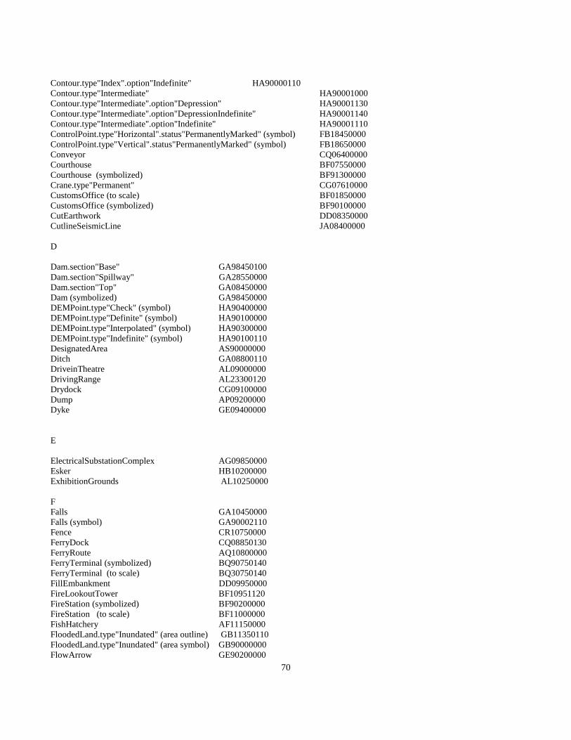
70
Contour.type"Index".option"Indefinite" HA90000110Contour.type"Intermediate" HA90001000Contour.type"Intermediate".option"Depression" HA90001130Contour.type"Intermediate".option"DepressionIndefinite" HA90001140Contour.type"Intermediate".option"Indefinite" HA90001110ControlPoint.type"Horizontal".status"PermanentlyMarked" (symbol) FB18450000ControlPoint.type"Vertical".status"PermanentlyMarked" (symbol) FB18650000Conveyor CQ06400000Courthouse BF07550000Courthouse (symbolized) BF91300000Crane.type"Permanent" CG07610000CustomsOffice (to scale) BF01850000CustomsOffice (symbolized) BF90100000CutEarthwork DD08350000CutlineSeismicLine JA08400000
D
Dam.section"Base" GA98450100Dam.section"Spillway" GA28550000Dam.section"Top" GA08450000Dam (symbolized) GA98450000DEMPoint.type"Check" (symbol) HA90400000DEMPoint.type"Definite" (symbol) HA90100000DEMPoint.type"Interpolated" (symbol) HA90300000DEMPoint.type"Indefinite" (symbol) HA90100110DesignatedArea AS90000000Ditch GA08800110DriveinTheatre AL09000000DrivingRange AL23300120Drydock CG09100000Dump AP09200000Dyke GE09400000
E
ElectricalSubstationComplex AG09850000Esker HB10200000ExhibitionGrounds AL10250000
FFalls GA10450000Falls (symbol) GA90002110Fence CR10750000FerryDock CQ08850130FerryRoute AQ10800000FerryTerminal (symbolized) BQ90750140FerryTerminal (to scale) BQ30750140FillEmbankment DD09950000FireLookoutTower BF10951120FireStation (symbolized) BF90200000FireStation (to scale) BF11000000FishHatchery AF11150000FloodedLand.type"Inundated" (area outline) GB11350110FloodedLand.type"Inundated" (area symbol) GB90000000FlowArrow GE90200000
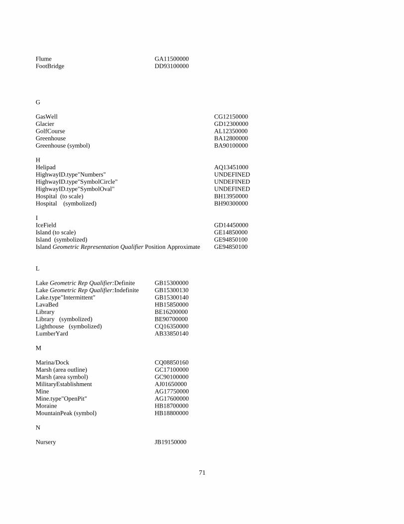
71
Flume GA11500000FootBridge DD93100000
G
GasWell CG12150000Glacier GD12300000GolfCourse AL12350000Greenhouse BA12800000Greenhouse (symbol) BA90100000
HHelipad AQ13451000HighwayID.type"Numbers" UNDEFINEDHighwayID.type"SymbolCircle" UNDEFINEDHighwayID.type"SymbolOval" UNDEFINEDHospital (to scale) BH13950000Hospital (symbolized) BH90300000
IIceField GD14450000Island (to scale) GE14850000Island (symbolized) GE94850100Island Geometric Representation Qualifier Position Approximate GE94850100
L
Lake Geometric Rep Qualifier:Definite GB15300000Lake Geometric Rep Qualifier:Indefinite GB15300130Lake.type"Intermittent" GB15300140LavaBed HB15850000Library BE16200000Library (symbolized) BE90700000Lighthouse (symbolized) CQ16350000LumberYard AB33850140
M
Marina/Dock CQ08850160Marsh (area outline) GC17100000Marsh (area symbol) GC90100000MilitaryEstablishment AJ01650000Mine AG17750000Mine.type"OpenPit" AG17600000Moraine HB18700000MountainPeak (symbol) HB18800000
N
Nursery JB19150000

72
O
OilWell CG19600000Orchard JB19650000

73
PPark/PicnicArea AL20150000Penitentiary BF20950000Penitentiary (symbolized BF90400000PhotoCentre (symbol) FD21100000Pier/Wharf (to scale) CQ21250000Pier/Wharf (symbolized) CQ90000120Pile AG21275000Pipeline EA21400000Pit.type"Abandoned" AG21550001Pit.type"GravelSand" AG21550000PoliceStation BF22000000PoliceStation (symbolized) BF90500000PostOffice BF22250000PostOffice (symbolized) BF90600000
QQuarry.type"WaterFilled" GB22500000
RRaceTrack AL22650000RailLine.type"AbandonedTrack" DE22950001RailLine.type"DoubleTrack" DE22850000RailLine.type"MultipleTrack" DE22900000RailLine.type"SingleTrack" DE22950000RailLine.type"Spur" DF28850000Rapids GA23500000Rapids (symbol) GA23500110Reservoir Geometric Rep Qualifier: Definite GB24300000Reservoir Geometric Rep Qualifier :Indefinite GB90100000Reservoir.type"Intermittent" GB90100110Reservoir.type"ProposedMaxResLevel" GB90100120RifleRange AL23300140 River/Stream Geometric Rep Qualifier: Definite GA24850000River/Stream Geometric Rep Qualifier: Indefinite GA24850140River/Stream.type"Dry" GA24850130River/Stream.type"Intermittent" GA24850150River/Stream.type"LeftBank" GA90000110River/Stream.type"RightBank" GA90000120Road.surface"Loose".lanes"1".type"Undivided" DA25000110Road.surface"Loose".lanes"1".type"Undivided".status"U/C" DA25000160Road.surface"Loose".lanes"2".type"Undivided" DA25000120Road.surface"Loose".lanes"2".type"Undivided".status"U/C" DA25000170Road.surface"Paved".lanes"1".type"Undivided" DA25100180Road.surface"Paved".lanes"1".type"Undivided".status"U/C" DA25100320Road.surface"Paved".lanes"2".type"Divided" DA25050180Road.surface"Paved".lanes"2".type"Divided".status"U/C' DA25050310Road.surface"Paved".lanes"2".type"Undivided" DA25300190Road.surface"Paved".lanes"2".type"Undivided".status"U/C" DA25300330Road.surface"Paved".lanes"3".type"Undivided" DA25100200Road.surface"Paved".lanes"3".type"Undivided".status"U/C" DA25100340Road.surface"Paved".lanes"4".type"Divided" DA25050190Road.surface"Paved".lanes"4".type"Divided.status"U/C" DA25050320Road.surface"Paved".lanes"4".type"Undivided" DA25100210Road.surface"Paved".lanes"4".type"Undivided".status"U/C" DA25100350Road.surface"Paved".lanes"6".type"Divided" DA25050200Road.surface"Paved".lanes"6".type"Divided".status"U/C" DA25050330

74
Road.surface"Paved".lanes"6".type"Undivided" DA25100220Road.surface"Paved".lanes"6".type"Undivided".status"U/C" DA25100360Road.surface"Rough" DA25150000
SSand/GravelBar (area outline) GE25850000Sand/GravelBar (area symbol) GE90100000School BE26000000School (symbolized) BE90900000Scree HB26150000SeaWall GE26250000SettlingPond EA26700100SewageTreatmentArea AP26750000Silo CA27500000Silo (symbol) BA90000110Sinkhole (symbol) HB27550000SkiJump CL27750000SkiLift CL27800000Slide (area outline) HB27900000Slide (area symbol) HB90000000SmokestackChimney CG28300100SmokestackChimney (symbol) CG28300000Snowshed DD28350000SportTrack AL22650110SportsField AL21900000SpotHeight (symbol) HA28700000Spring (symbol) GF28750000StockYard AB33850150Swamp (area outline) GC30050000Swamp (area symbol) GC90200000
TTailingArea AP30300000TailingPond AP90300100Tank EA30400000Tank (symbol) EA90000000Text.type"AerialTriangulation" KC90000000Text.type”Generic” KC91000000Text.type"Hydrographic" KB14250000Text.type"HypsographicContourNumbers" KC14300130Text.type"HypsographicExcludingContourNumbers" KC14300000Text.type"LandCover" KC14300310Text.type"LandForm" KC90500000Text.type"Landmark" KC90200000Text.type"Toponymy" KC90300000Text.type"Transportation" KC90100000TollGate DD31000000TollGate (symbol) DD91000000Tower.type"Microwave" CC31152110Tower.type"Transmission" CC90000000Tower.type"Unspecified" (symbol) CC31150000Trail DD31700000TrailerPark AN31950000TransmissionLine.type"Hydro" EA16400120Trestle DD93200000Tunnel DD93220000Turntable DD32300000
75
UUniversity BE32400000
VVineyard JB32800000VolcanicCrater HB07650130
WWall.type"Retaining" DD24600000WaterLevel(DateofPhotography) (symbol) HA33100000WaterTower (symbol) EA31050110WeighScale CG33250000WoodedArea JA33750000
YYard AB33850000
ZZoo AL33900000

76
Section 2 Detailed Geographic Object Specifications

77
Section 2 - Detailed Geographic Object Specifications
2.1 General Notes
The following section will provide the user or supplier of 1:20 000 digital baseline data with a detailed specification of eachpossible feature that is relevant to this discipline at this scale. The intention is to provide specifications in a vendor and programindependent way. In this release, codes are included that are necessary to support existing contractual programs, but future releasesmay only contain code references as correlation tables found in the appendices. All measurements and display parameter guidelinesrequired to generate verification plots and to interpret representational products are explicitly included in each feature table. Themeasurements in the detailed section are stated in millimetres at map scale. All display guidelines are stated in vendor independentterms, e.g. colour is given as BLUE rather than a vendor dependent parameter such as “002". To facilitate updating of feature tables,this section is alphabetically arranged without page numbering. This will allow for the insertion of addenda when required withoutthe need for section reprinting and index generation.
All digital data shall be digitized and edited in accordance with the guidelines provided in Part I Section 5.
All digital data files shall be coded (i.e. feature code and feature type) in accordance with the detailed specifications provided inPart II Section 2.
Contours will be generated by computer interpolation from the Digital Elevation Model compiled in stereo compilation.
Contour interpolation will be achieved using computer software previously approved by the Branch.
Part II Section 1 contains indices to map features found in the detailed specification section.
Part II Section 2.2 contains instructions on the use of the detailed specification section.
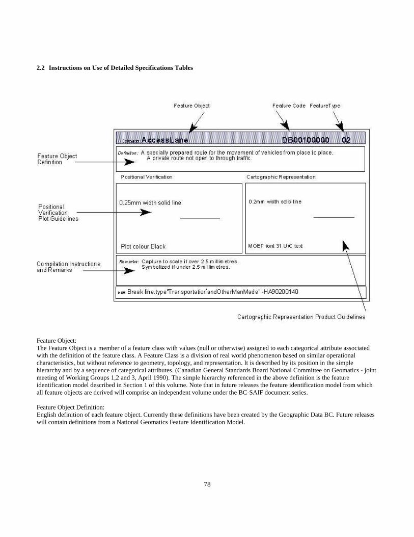
78
2.2 Instructions on Use of Detailed Specifications Tables
Feature Object:The Feature Object is a member of a feature class with values (null or otherwise) assigned to each categorical attribute associatedwith the definition of the feature class. A Feature Class is a division of real world phenomenon based on similar operationalcharacteristics, but without reference to geometry, topology, and representation. It is described by its position in the simplehierarchy and by a sequence of categorical attributes. (Canadian General Standards Board National Committee on Geomatics - jointmeeting of Working Groups 1,2 and 3, April 1990). The simple hierarchy referenced in the above definition is the featureidentification model described in Section 1 of this volume. Note that in future releases the feature identification model from whichall feature objects are derived will comprise an independent volume under the BC-SAIF document series.
Feature Object Definition:English definition of each feature object. Currently these definitions have been created by the Geographic Data BC. Future releaseswill contain definitions from a National Geomatics Feature Identification Model.
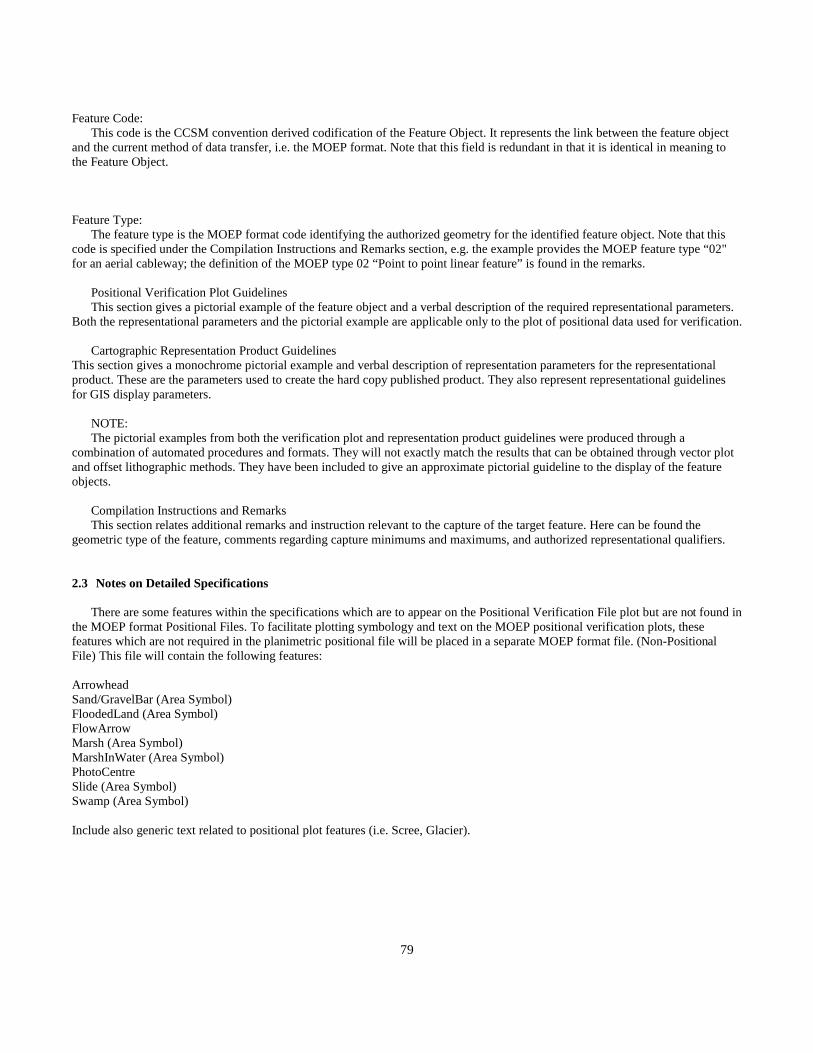
79
Feature Code: This code is the CCSM convention derived codification of the Feature Object. It represents the link between the feature objectand the current method of data transfer, i.e. the MOEP format. Note that this field is redundant in that it is identical in meaning tothe Feature Object.
Feature Type: The feature type is the MOEP format code identifying the authorized geometry for the identified feature object. Note that thiscode is specified under the Compilation Instructions and Remarks section, e.g. the example provides the MOEP feature type “02"for an aerial cableway; the definition of the MOEP type 02 “Point to point linear feature” is found in the remarks.
Positional Verification Plot Guidelines This section gives a pictorial example of the feature object and a verbal description of the required representational parameters.Both the representational parameters and the pictorial example are applicable only to the plot of positional data used for verification.
Cartographic Representation Product GuidelinesThis section gives a monochrome pictorial example and verbal description of representation parameters for the representationalproduct. These are the parameters used to create the hard copy published product. They also represent representational guidelinesfor GIS display parameters.
NOTE: The pictorial examples from both the verification plot and representation product guidelines were produced through acombination of automated procedures and formats. They will not exactly match the results that can be obtained through vector plotand offset lithographic methods. They have been included to give an approximate pictorial guideline to the display of the featureobjects.
Compilation Instructions and Remarks This section relates additional remarks and instruction relevant to the capture of the target feature. Here can be found thegeometric type of the feature, comments regarding capture minimums and maximums, and authorized representational qualifiers.
2.3 Notes on Detailed Specifications
There are some features within the specifications which are to appear on the Positional Verification File plot but are not found inthe MOEP format Positional Files. To facilitate plotting symbology and text on the MOEP positional verification plots, thesefeatures which are not required in the planimetric positional file will be placed in a separate MOEP format file. (Non-PositionalFile) This file will contain the following features:
Arrowhead Sand/GravelBar (Area Symbol) FloodedLand (Area Symbol) FlowArrow Marsh (Area Symbol) MarshInWater (Area Symbol)PhotoCentre Slide (Area Symbol) Swamp (Area Symbol)
Include also generic text related to positional plot features (i.e. Scree, Glacier).
80
2.3.1 Remarks - Aerial Triangulation and Related Features
Photo centres and permanently marked control points are the only aerial triangulation features to be contained in the MapRepresentational Data Files.
2.3.2 Remarks - Hydrographic and Related Features
See Figure II.2.1 for a graphic illustration of the following remarks.All distances, unless other specified are at map scale, not ground scale.
For the purpose of these specifications, drainage related features have been divided into two distinct classifications:
i. Tidalii. Non-tidalThe point at which tidal water features change to non-tidal water features will be specified for each project.
The intention is to show natural and manmade hydrographic features that are continuous for a distance of over 10 millimetres inlength.
All graphic elements depicting hydrographic features having a discernible gradient must be digitized in a downstream direction, e.g.rivers, streams, canals, ditches.
Where hydrographic features pass under roads or other linear features, the continuity of the digital data must be retained in the mapposition file (e.g. Do not break the feature for bridges or dams, etc. There will be a node placed at point of intersection.).
Culverts shall not be captured.
Rivers/streams shall be shown as continuous, even though flowing through lake features that are below the minimum sizespecification, or through swamp or marsh areas. (Hanging drainage will be avoided when possible.)
Ditches shall only be captured if they form part of the main drainage system.
The apparent high water mark of any lake, or other body of water is where the presence and action of the water are so common andusual as to mark on the soil of the bed of the body of water a character distinct from that of its banks, in vegetation, as well as in thenature of the soil itself.
NOTE: For purpose of these specifications, the following are all defined by their apparent high water marks:- Coastline (Tidal)- River Double Line- Lake- Reservoir

81
Island features in rivers/streams and lakes which are not covered by water and are greater than 1 millimetre (map scale) in length onlongest side will be captured to scale. Sand/gravel in rivers/streams and lakes which are not covered by water (date of photography)and are greater than 1 millimetres (map scale) in width and 5 millimetres (map scale) in length will be captured to scale.
Sand / gravel in rivers / streams and lakes which are not covered by water (date of photography) and are greater than 20 metres inwidth and 75 metres in length will be captured to scale.
The lake feature code will be used for any natural, permanent body of water having a longest side greater than 25 metres.
The reservoir feature code will be used for any body of water having a longest side greater than 25 metres.
Ministry of Environment, Lands and Parks official toponymy sheets will be used to ensure that all named creeks are captured.
Feature ArrowHead. For clarification, the arrow head is to be placed where split streams occur (on the lesser stream).
Feature Sinkhole. For clarification, this arrow head is to be attached to hanging drainage to show the direction of flow and to clarifythe stream's termination.
When lake polygons, coastline, double sided rivers are closed with a double sided river, node the left and right river banks to thelake, coastline, and double sided river. To close double sided rivers flowing into a lake or ocean continue the left bank and code as aconstruction line.To close double sided rivers flowing out of a lake continue the right bank and code as a construction line. When a double sidedriver meets another double sided river, close the lesser feature as left bank; show the closing line of the lesser feature and thecorresponding major river line as construction (similar to a double sided river flowing into lake).When a double sided river branches into two or more double sided rivers forming a delta as it joins a lake or an ocean, the landmasses between the branches are coded as islands.The island line which is coincident with the lake will be primary and the lake and river-left bank will be construction.
Duplicate swamps as trees when next to clearing. Do not duplicate swamp as trees when next to trees. See fig.II.2.6
Major dams will be captured by showing a dam top and a dam base when visible. Both the dam top and the dam base will becaptured as closed polygons with the dam top taking precedence. In the event that the dam base is partially visible the dam topoutline will be duplicated at the appropriate water level to provide a closed polygon for the dam base. Roads that traverse the damtop will be captured as road (gravel - 1 lane) at all times.
Spillways - Roads crossing spillways will be shown as a bridge to scale. Spillway bridges are not shown on the representational file.
Coastal (Tidal) – When a tidal situation occurs, the apparent high water mark will be captured as “Coastline”. Only named features,i.e., islands, beaches, will be captured below the high water mark. The intent is to capture only the apparent high water mark intidal areas.
When a dry river bed/oxbow which is not subject to annual flooding joins a double line river, the junction is to be closed using asolid visible line (left or right bank). The dry river bed is to captured as a closed polygon.
If an oxbow has water in it and not joined to a double sided river then capture as a lake. If the oxbow has water in it and is joined toa double side river at one end, capture as part of the river. If the oxbow is dry then capture as a dry river bed.
Either definite or intermittent drainage may have portions classified as indefinite in limited situations when the water course isobscured by vegetation, shadow, etc. A definite stream cannot flow into an intermittent stream.
When there is a series of lakes separated by beaver dams, code each lake separately creating closed polygons by duplicating thebeaver dam only if the lake elevation is differences are greater than 5 metres. If the lake elevation is less than 5 metres code theentire body of water as one lake. In this case the beaver dam will run across the lake. This is probably the more common case sincethe beaver dams are seldom more than 1 to 2 metres high. For beaver dams across rivers the left and right river banks are shown.

82
Beaver dams as well as other dams are to be digitized as the primary feature over lake edges. The right side of the dam is to be thedownstream side.
When a dam has a coincident side to the hydrographic feature such as a lake or coastline, the construction lake or coastline is to bemanually added to the DEM as a hydrographic breakline to ensure the breakline polygon closes.
Vancouver Island and the Queen Charlotte Islands (2 main islands) are to be coded as coastline. All other islands are to be coded asislands.
Dugouts are not a valid feature for data capture. If a dugout has a longest dimension over 25 metres than capture it as a lake.
Sand is not captured on glaciers even if the NTS 1:50 000 shows sand on them.
For large icefields that have a number of glaciers coming off them, capture the whole feature as a glacier if possible. If the plotteroperator sees it as more than one distinct feature than it may be captured as such. The glacier would than be the main feature withthe icefield as construction with the dividing line determined by the operator.
Marshes can occur above and below the high water mark or both. Capture each as separate features duplicating the lake line asmarsh when they are coincident.
Swamps cannot occur inside lakes. This would imply trees inside the lake. This condition can only occur in inundated land.
Rapids to scale are to be noded to the left and right river bank. When there is a sandbar along one side of the bank, the rapids are togo through the sandbar (noded) and end at the bank.
Intermittent rivers can flow out of intermittent lakes.
Sinkholes are not to be used at the ends of river / stream features when they enter glaciers or icefields. The stream should terminatewith a node at the glacier / icefield edge. If a major stream or named stream flows through a glacier, the stream must be shown tobe continuous, with a construction line.
Snow that is intermittent (melts at some point during the year) should not be captured. Creeks and rivers should be connectedthrough these areas as definite features.

83
Figure II.2.1Sample Diagram Illustrating Digitizing Conventions as Applied to the Mica Dam
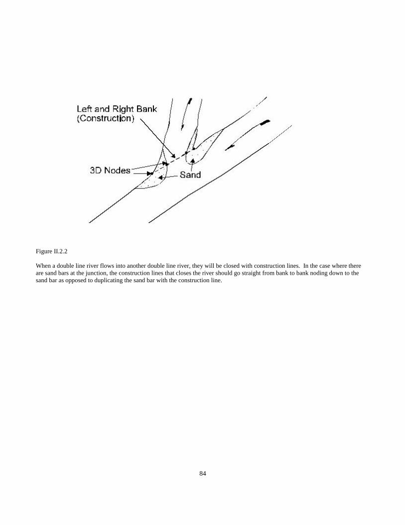
84
Figure II.2.2
When a double line river flows into another double line river, they will be closed with construction lines. In the case where thereare sand bars at the junction, the construction lines that closes the river should go straight from bank to bank noding down to thesand bar as opposed to duplicating the sand bar with the construction line.

85
Figure II.2.3
When a double line river branches into two or more double line rivers forming a delta as it joins a lake or an ocean, code the landmass between the branches as islands. This will simplify the procedure of closing the branches. In this case, the island line whichis coincident with the lake will be primary and the lake and left bank will be construction.
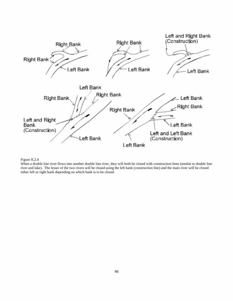
86
Figure II.2.4When a double line river flows into another double line river, they will both be closed with construction lines (similar to double lineriver and lake). The lesser of the two rivers will be closed using the left bank (construction line) and the main river will be closedeither left or right bank depending on which bank is to be closed.
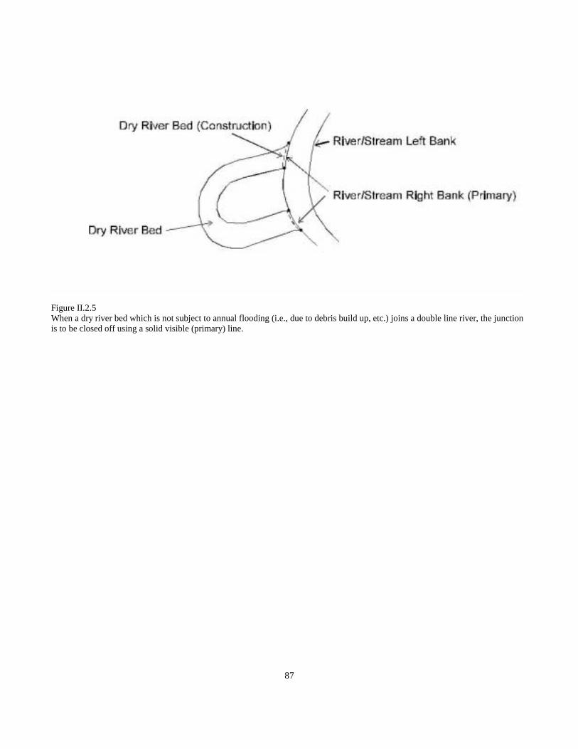
87
Figure II.2.5When a dry river bed which is not subject to annual flooding (i.e., due to debris build up, etc.) joins a double line river, the junctionis to be closed off using a solid visible (primary) line.
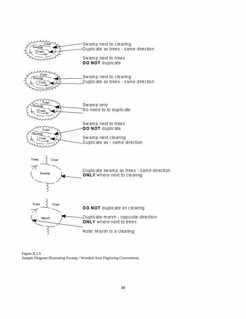
88
Figure II.2.6Sample Diagram Illustrating Swamp / Wooded Area Digitizing Conventions.

89
Figure II.2.7Sample Diagram Illustrating Digitizing Conventions for Hydrographic and Related Features

90
Figure II.2.8Lakes that fall inside a designated area are not to be duplicated as construction line designated areas.

91
2.3.3 Remarks - Hypsographic, Landform, and Related Features
Positional File
(a) Map relief will be collected in the form of a Digital Elevation Model of sufficient quality and quantity to meet the accuracystandards as laid out in this manual.
Piles will be outlined and labelled if they meet minimum size criteria. DEM data will not be collected and they will not becontoured. They will be treated as a DEM area of exclusion.
Active pits, open pit mines, and quarries will be outlined and labelled if they meet minimum size criteria. DEM data, exceptingbreaklines, will be collected, but they will not be contoured. They will be treated as a DEM area of exclusion.
Pits or quarries that are obviously abandoned will be collected in the DEM and contoured.
DEM points will be collected over swamps and marshes but not over lakes.
Unless specified otherwise, map relief will be shown by a 1 metre and 0.5 metre contour interval interpolated from Digital ElevationModel data using interpolation software approved by the Branch.
Depression contours are to be shown in both the Positional (POS) and the Representational (REP) files. Depressions falling on asheet edge will continue to be shown as depressions if the DEM which extends beyond the map sheet boundary can confirm this.
Areas obscured by cloud will be captured from alternate photography.
The DEM should be captured in one direction only, i.e., from the bottom to the top of the model.
Spot heights are distinct points of measured height. In flat areas a minimum of one spot height every 1000m is required. Spotheights shall be displayed to the closest metre. Spot heights are not required on bridges; however, they may be shown at road andcutline intersections.
DEM points are not captured on dam faces.
DEM points in non permanent snow reflect the true ground elevation.
Out-wash plains which are formed at the bottom of moraines are included as part of the moraine.
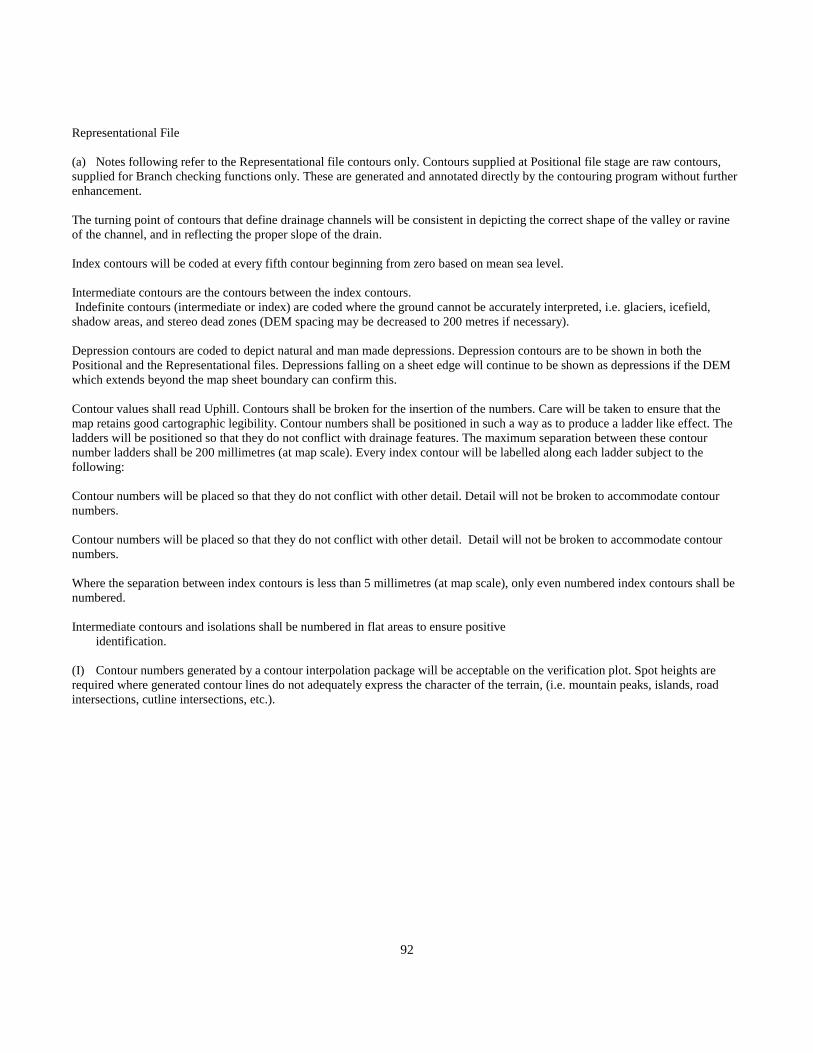
92
Representational File
(a) Notes following refer to the Representational file contours only. Contours supplied at Positional file stage are raw contours,supplied for Branch checking functions only. These are generated and annotated directly by the contouring program without furtherenhancement.
The turning point of contours that define drainage channels will be consistent in depicting the correct shape of the valley or ravineof the channel, and in reflecting the proper slope of the drain.
Index contours will be coded at every fifth contour beginning from zero based on mean sea level.
Intermediate contours are the contours between the index contours. Indefinite contours (intermediate or index) are coded where the ground cannot be accurately interpreted, i.e. glaciers, icefield,shadow areas, and stereo dead zones (DEM spacing may be decreased to 200 metres if necessary).
Depression contours are coded to depict natural and man made depressions. Depression contours are to be shown in both thePositional and the Representational files. Depressions falling on a sheet edge will continue to be shown as depressions if the DEMwhich extends beyond the map sheet boundary can confirm this.
Contour values shall read Uphill. Contours shall be broken for the insertion of the numbers. Care will be taken to ensure that themap retains good cartographic legibility. Contour numbers shall be positioned in such a way as to produce a ladder like effect. Theladders will be positioned so that they do not conflict with drainage features. The maximum separation between these contournumber ladders shall be 200 millimetres (at map scale). Every index contour will be labelled along each ladder subject to thefollowing:
Contour numbers will be placed so that they do not conflict with other detail. Detail will not be broken to accommodate contournumbers.
Contour numbers will be placed so that they do not conflict with other detail. Detail will not be broken to accommodate contournumbers.
Where the separation between index contours is less than 5 millimetres (at map scale), only even numbered index contours shall benumbered.
Intermediate contours and isolations shall be numbered in flat areas to ensure positiveidentification.
(I) Contour numbers generated by a contour interpolation package will be acceptable on the verification plot. Spot heights arerequired where generated contour lines do not adequately express the character of the terrain, (i.e. mountain peaks, islands, roadintersections, cutline intersections, etc.).

93
Figure II.2.2
Sample Diagram Illustrating Digitizing Conventions for Hypsographic, Landform, and Related Features.

94
2.3.4 Remarks - Land Cover and Related Features
The intent is to show all areas of wood areas that have a crown closure of 6% or greater and cover an area greater than 1.0 hectare.Areas that are evenly distributed with wooded area polygons may be grouped together if they cover 60% of the total area inquestion.Wooded area boundaries along rightofways (i.e., Roads, Transmission lines, etc.) will not be captured unless the rightofway is 40mor greater in width.Naturally occurring or man-made clearings of 1.0 hectares or greater that are enclosed within wooded area as defined above will beshown as “holes” in the wooded area polygon, i.e., the lines bounding the non-wooded area are coded as wooded area features withthe forest to the right of the line and the clearing to the left of the line.
Particular care will be taken to show the true shape of non-wooded areas in extensive wooded areas.
Forestry cut blocks which do not show obvious signs of substantial regeneration (2 metres or more) will be shown as non-woodedareas. Scrub and sparse trees of less than 6% coverage will be shown as non-wooded areas.
Where land cover features and any other features are contiguous, the land cover feature will not be shown in the RepresentationalFile. The land cover polygon will be closed in the Positional file by exact numeric copy of the contiguous feature. The Right Handrule must be adhered to.
Areas of standing dead trees (burnt or diseased) are captured as wooded areas. Areas of fallen dead trees are captured as non-wooded areas.
Wooded areas that meet the above requirements are shown in lava beds.
Nurseries, orchards and vineyards are not captures as wooded areas. When they fall within or beside a wooded area they are treatedas sepatate polygons.
The intent is to show all wooded areas that are greater than 1 hectare in size and more than 60% crown closure. Treed areas thatsatisfy the above criteria are considered significant land cover and must be shown even within built up areas.
When pit and orchard lines are coincident, the pit is compiled as the primary feature and the orchard as a secondary constructionfeature.

95
Figure II.2.3Sample Diagram Illustrating Digitizing Conventions for Land Cover and Related Features.

96
2.3.5 Remarks - Landmark and Related Features
All buildings with one side greater than 30m or an area larger than 900 square metres shall be captured to scale using the right handrule. Buildings less than 900 square metres in area shall be symbolized and will be oriented to their true ground position. Buildingdimensions shall be determined by the outline of their roofs, including attached garages, and multilevel parking.
Only major transmission lines shall be captured. This feature shall be captured as a set of connecting points, captured at individualtowers, if visible. Transmission towers will not be plotted at representational stage. Height of towers will be recorded as anattribute if they are over 30 metres and can be measured.
Area outlines shall be captured as a set of connecting points along the perimeter of the feature.
All area features must be closed explicitly with right hand rule.
The duplicate lines generated by closing features must be identical for processing MOEP format data. Only the highest in therepresentational display hierarchy will be coded as visible, all other duplicate lines will be coded as invisible (in the MOEP transferformat use the constructions feature types 12 and 13).
Area features need not be closed at map sheet boundaries, but where a feature meets a sheet edge, the node describing the end ofthat feature on the boundary must be numerically identical to the starting point of that feature on the adjoining sheet. This rule willapply to all features.
Non-permanent features such as lumber, cranes, etc. will not be shown in areas identified by an area outline.
Schools, churches, hospitals and refinery buildings that are obvious landmark features shall be captured, even if they are within anarea outline or built-up area.
An area will be designated as built-up if it consists of an area approximately equal to 10 full city blocks, or 25 hectares.
(g) Homes in a Trailer Park will be captured at Pos stage but only an approximate number will be shown in the Rep file. WhenTrailer Parks are part of a built-up area the homes will not be captured.Use the pier/wharf classification with the generic text “Sea Plane Base” to capture seaplane bases.
The hierarchy of coincident designated areas will be alphabetic as listed in the specification.
Abandoned open pit mines should be captured using the abandoned pit feature code. DEM points should be collected in this areaand contours should be shown.
For pipelines that use bridges to cross rivers or gullies, stop the pipeline and join to the bridge, start the pipeline again at the end ofthe bridge. Do not duplicate the bridge for the pipeline. The bridge becomes part of the pipeline network.
Fences are captured on the ground and are noded either 2D or 3D with crossing features. Fences are captured similar totransmission lines, i.e., if the fence is straight, a point at the beginning and a point at the end is sufficient. Fences are only capturedwhen they are clearly visible. Fences along roads may not be captured.
Placer mines are captured using the same feature code as Mine.”OpenPit”. Placer mine text is placed in the toponymy overlay asreferenced by the 1:50 000 map sheet.
Borrow pits are coded as Pit”Abandoned”. Note: borrow pits may contain lakes.
Pipelines are captured as continuous features across a map sheet. Pipelines are coded as construction when they are coincident withother features such as roads and streams. Pipelines are coded as primary when they are coincident with wooded areas or otherdesignated areas. Pipelines may not be continuous when crossing areas such as built-up areas where exact position is determined.

97
Residential complexes greater than 900 square metres in area that are 15 metres or less in height (e.g., town house complexes. Rowhousing, small apartment complexes) are not considered significant landmark features. Consequently, they need not be capturedwithin built-up areas. However, residential complexes greater than 900 square metres in area that are more than 15 metres heightare to be considered significant landmark features and so must be captured within built-up areas.
The intent is to show all wooded areas that are greater than 1 hectare in size and more than 60% crown closure. Treed areas thatsatisfy the above criteria are considered significant land cover features and must be shown even within built-up areas.
When pit and orchard lines are coincident, the pit is compiled as the primary feature and the orchard as a secondary constructionfeature.

98
Figure II.2.4Sample Diagram Illustrating Digitizing Conventions for Landmark and Related Features

99

100
2.3.6 Remarks - Text Features
Text information shall be positioned to ensure clarity of feature presentation on the final cartographic separations and to enhanceclarity of feature recognition.
Text information shall be positioned in such a way that it does not conflict with any other map features.
Generic names only will be added at the data capture stage. All text used to clarify the verification plots will be placed in thenon-positional file and will not appear in the positional file (i.e. Scree, Glacier).
Additional information concerning Toponymy is provided in the appendices.

101
2.3.7 Remarks - Transportation and Related Features
The intention is to show all roads, access roads and railways.
These features shall be captured as a single line defining the apparent centreline of the feature and will reflect all horizontal andvertical deflections required to meet the horizontal and vertical accuracy specifications.
All 6 lane roads and divided roads separated by more than 50 metres (centreline to centreline) shall be captured as single linesdefining the apparent centre line of each roadway. Thus the two roadways will be digitized separately.
Bridges, trestles, tunnels and snowsheds will be captured to scale, regardless of size, as single lines defining the apparent centreline.The width of bridges and trestles will be recorded in the 05 record for that feature. Do not duplicate these features as roads orrailways.
The line which defines a cut or fill is not a closed polygon. This line is captured on the high side of the feature and must follow theright hand rule. The digitizing direction of the line is important because the ticks that are patterned at the representational plot stageare on the right side of the line and must point to the low side of the feature.
Cutlines are not duplicated when they are coincident with roads or streams.
When a cutline continues through a wooded area into anon-wooded area it is shown as a continuous feature when it is clearly visiblein the non-wooded area and cannot be identified as another feature.
The Prince Rupert to Port Hardy and the Prince Rupert to Skagway ferry routes are not captured.
Driveways and lanes that are over 400m in length are captured as either a gravel road or a rough road.
When roads occur on dykes, capture the dyke as the primary feature and the road as the secondary construction feature.
One lane on / off ramps on major highways and freeways are coded as Road.”Paved”.”1”.”Undivided” DA25100180.
Where major highways are divided and opposing lanes of traffic are separated by less than 50 metres but are at different elevations,the opposing lanes of traffic must be captured as separate features to properly capture the difference in elevation. (e.g., for a 4 lanedivided highway capture as two 2 lane one way road features).

102
Figure II.2.5Sample Diagram Illustrating Digitizing Conventions for Transportation and Related Features

103
2.4 - Detailed Specifications

104
A
Subclass: AerialCableway CQ00300000 02Definition: A transportation device for freight or passangers consisting of a carrier and a cablesupported by towers.
Positional Verification Cartographic Representation0.25mm width line 0.35mm width solid line
plot colour BLACK MOEP font 31 UPPER CASE textRemarks:
• Captured to scale in the positional file.• Identification coded as Text.type"Transportation" in the non-positional file.
DEM N
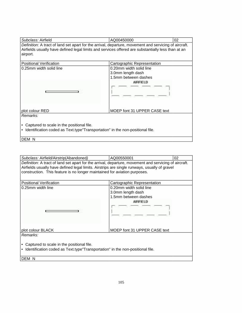
105
Subclass: Airfield AQ00450000 02Definition: A tract of land set apart for the arrival, departure, movement and servicing of aircraft.Airfields usually have defined legal limits and services offered are substantially less than at anairport.
Positional Verification Cartographic Representation0.25mm width solid line 0.20mm width solid line
3.0mm length dash1.5mm between dashes
plot colour RED MOEP font 31 UPPER CASE textRemarks:
• Captured to scale in the positional file.• Identification coded as Text.type"Transportation" in the non-positional file.
DEM N
Subclass: Airfield/Airstrip(Abandoned) AQ00550001 02Definition: A tract of land set apart for the arrival, departure, movement and servicing of aircraft.Airfields usually have defined legal limits. Airstrips are single runways, usually of gravelconstruction. This feature is no longer maintained for aviation purposes.
Positional Verification Cartographic Representation0.25mm width line 0.20mm width solid line
3.0mm length dash1.5mm between dashes
plot colour BLACK MOEP font 31 UPPER CASE textRemarks:
• Captured to scale in the positional file.• Identification coded as Text.type"Transportation" in the non-positional file.
DEM N

106
Subclass: Airport AQ00500000 02Definition: A tract of land set apart for the arrival, departure, movement and servicing of aircraft:licensed by Transport Canada, having paved and lighted runways, and operationg a controltower.
Positional Verification Cartographic Representation0.25mm width line 0.25mm width line
plot colour REDRemarks:
• Capture to scale in the positional file.
DEM N
Subclass: Airstrip AQ00550000 02Definition: A tract of land, consisting of a single runway, usually of gravel construction, set apartfor the arrival, departure and movement of aircraft.
Positional Verification Cartographic Representation0.25mm width line 0.20mm width solid line
3.0mm length dash
1.5mm between dashes
plot colour RED MOEP font 31 UPPER CASE textRemarks:
• Captured to scale in the positional file.• Identification coded as Text.type"Landmark" in the non-positional file.
DEM N

107
Subclass: AmmunitionDump AJ00650000 02/03Definition: A military installation used for the storage of explosives and other volatile materials,normally fenced and having a legal boundary.
Positional Verification Cartographic Representation0.20mm width solid line 0.20mm width solid line
3.0mm length dash 3.0mm length dash
1.5mm between dashes 1.5mm between dashes
plot colour BLACK MOEP font 31 UPPER CASE textRemarks:
• 1 hectare minimum• Capture to scale in the positional file• Identification coded as Text.type"Landmark" in the non-positional file
DEM N
Subclass: AreaofExclusion HC900000000 02/03Definition: An area outline in the DEM within which contours will not be interpolated.
Positional Verification Cartographic Representationapprox. 0.5mm dots
centre to centre - 1.5mm
plot colour REDRemarks:
• Area exempt from contour interpolation• Capture to scale in the positional file.• Not included in the representational file.
DEM Y

108
Subclass: AreaofIndefiniteContours HC90000100 02/03Definition: An area in the DEM which is outlined in such a manner that contours which areinterpolated within its boundary will be depicted as indefinite.
Positional Verification Cartographic Representationapprox. 0.5mm dots
centre to centre - 1.5mm
plot colour REDRemarks:
• Captured in the DEM file.• Not included in the representational file.
DEM Y
Subclass: Arrowhead GE90200110 01Definition: Hydrographic directional symbol
Positional Verification Cartographic Representation0.25mm width solid line 0.25mm width solid lineeach leg of arrowhead 1.5mm in length each leg of arrowhead 1.5mm in
length
45º Angle 45º Angle
> >
plot colour BLUERemarks:
• For clarification, the arrowhead is to be placed where split streams occur (on the lesserstream).• Although depicted on the varification plot this feature is not included in the positional data file• Capture in the non-positional file
DEM N

109
Subclass: AutoWrecker AB33850110 02/03Definition: An area set aside for the disposal of recycling of derelict automobiles.
Positional Verification Cartographic Representation0.25mm width line 0.25mm width line
3.9mm dash 3.9mm dash
1.5mm between dashes 1.5mm between dashes
plot colour BLACK MOEP font 31 UPPER CASE textRemarks:
• 1 hectare minimum• Capture to scale in the positionnal file• Identification coded as Text.type"Landmark" in the non-positional file
DEM N

110
B
Subclass: Barn (to scale) BA01540000 02
(Symbolized) BA90000000 01Definition: A large utility building on afearm complex.
Positional Verification CartographicRepresentation
To Scale Symbolized To Scale Symbolized
0.25mm width solid line 0.25mm width solid line 0.25mm width solid line 0.25mm width solidline
0.8mm open square 0.8mm filled square
plot colour BLACK
Remarks:
• Capture to scale in the positional file using the right hand rule when one side is > 30m. orthe total area is > 900 sq. m.• Capture as a point in the positional file oriented to the true ground position when total areais < 900 sq. m. with no sides > 30m.• Determine building dimensions by the outline of the roofs, including attached garages andmultilevel parking.DEM N
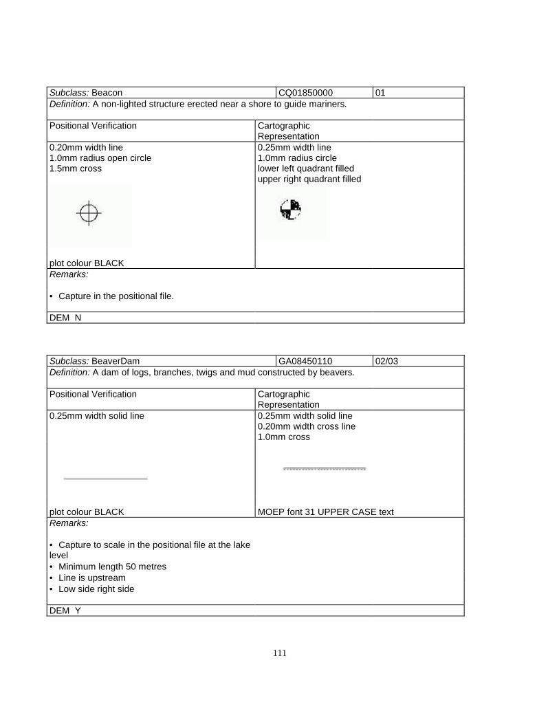
111
Subclass: Beacon CQ01850000 01Definition: A non-lighted structure erected near a shore to guide mariners.
Positional Verification CartographicRepresentation
0.20mm width line 0.25mm width line1.0mm radius open circle 1.0mm radius circle1.5mm cross lower left quadrant filled
upper right quadrant filled
plot colour BLACKRemarks:
• Capture in the positional file.
DEM N
Subclass: BeaverDam GA08450110 02/03Definition: A dam of logs, branches, twigs and mud constructed by beavers.
Positional Verification CartographicRepresentation
0.25mm width solid line 0.25mm width solid line0.20mm width cross line1.0mm cross
plot colour BLACK MOEP font 31 UPPER CASE textRemarks:
• Capture to scale in the positional file at the lakelevel• Minimum length 50 metres• Line is upstream• Low side right side
DEM Y
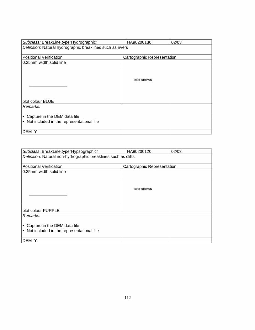
112
Subclass: BreakLine.type"Hydrographic" HA90200130 02/03Definition: Natural hydrographic breaklines such as rivers
Positional Verification Cartographic Representation0.25mm width solid line
plot colour BLUERemarks:
• Capture in the DEM data file• Not included in the representational file
DEM Y
Subclass: BreakLine.type"Hypsographic" HA90200120 02/03Definition: Natural non-hydrographic breaklines such as cliffs
Positional Verification Cartographic Representation0.25mm width solid line
plot colour PURPLERemarks:
• Capture in the DEM data file• Not included in the representational file
DEM Y

113
Subclass: BreakLine.type"Round" HA90200110 02/03Definition: A rounded breakline causes a smoother but still well defined deflection to the interpolatedcontour
Positional Verification Cartographic Representation0.25mm width solid line
plot colour BROWNRemarks:
• Captured in the DEM data file.• Not included in the representational file
DEM Y
Subclass: BreakLine.type"Sharp" HA90200000 02/03Definition: A sharp breakline causes a definite pointed character to the interpolated contour
Positional Verification Cartographic Representation0.25mm width solid line
plot colour BLACKRemarks:
• Captured in the DEM data file.• Not included in the representational file
DEM Y
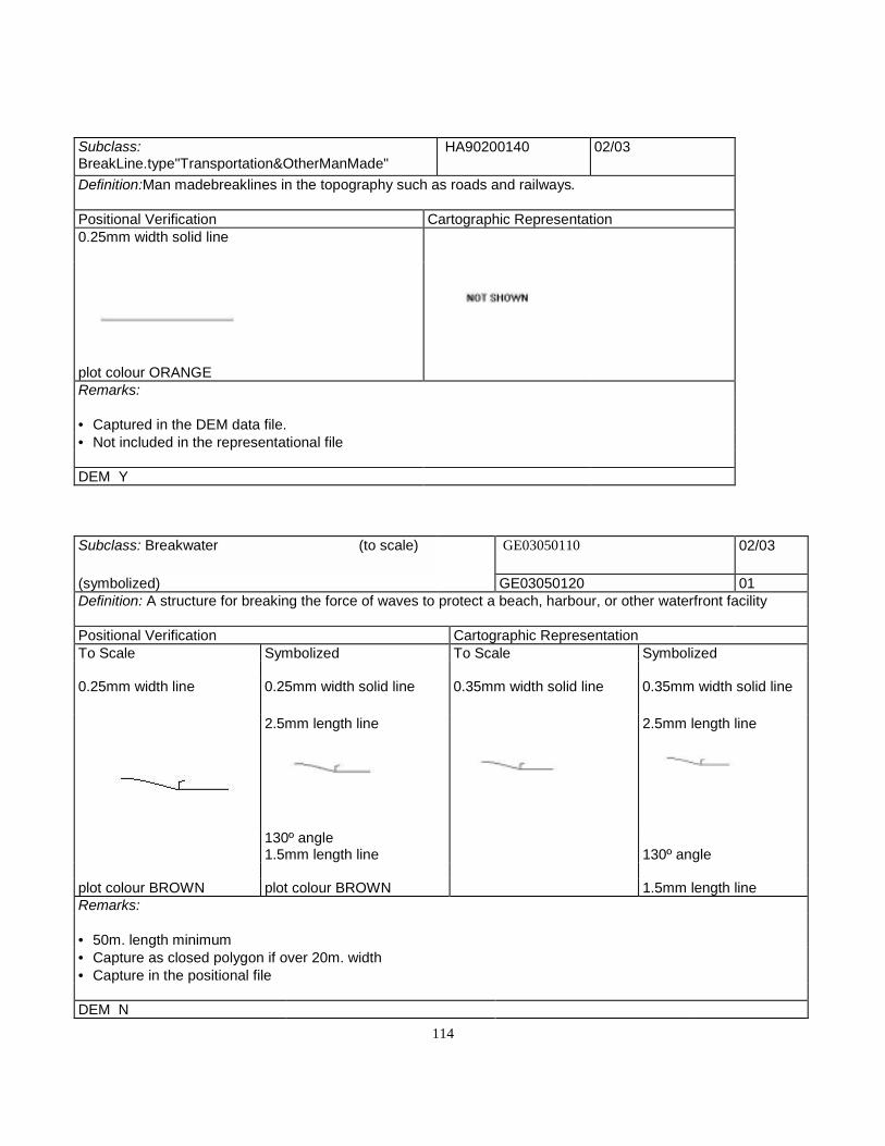
114
Subclass:BreakLine.type"Transportation&OtherManMade"
HA90200140 02/03
Definition:Man madebreaklines in the topography such as roads and railways.
Positional Verification Cartographic Representation0.25mm width solid line
plot colour ORANGERemarks:
• Captured in the DEM data file.• Not included in the representational file
DEM Y
Subclass: Breakwater (to scale) GE03050110 02/03
(symbolized) GE03050120 01Definition: A structure for breaking the force of waves to protect a beach, harbour, or other waterfront facility
Positional Verification Cartographic RepresentationTo Scale Symbolized To Scale Symbolized
0.25mm width line 0.25mm width solid line 0.35mm width solid line 0.35mm width solid line
2.5mm length line 2.5mm length line
130º angle1.5mm length line 130º angle
plot colour BROWN plot colour BROWN 1.5mm length lineRemarks:
• 50m. length minimum• Capture as closed polygon if over 20m. width• Capture in the positional file
DEM N

115
Subclass: Bridge DD93250000 03Definition: A structure erected along a travelled route to span a depression or obstacle
Positional Verification Cartographic Representation0.25mm width solid line BRIDGE DECK
1.6mm minimum width0.8mm wide0.35mm width solid line
LINE TERMINATOR
0.7mm length0.35mm line width45º angle
plot colour BLACKRemarks:
• Capture to scale in the positional file as a single line defining the apparent centre line• More than 40m. in length plot to scale• Capture width as type 05• Do not duplicate this feature as a road or railway
DEM N

116
Subclass: Building (to scale) BR90000000 02
(symbolized) BR90000110 01Definition: A generic term for any permanent walled and roofed construction
Positional Verification Cartographic RepresentationTO SCALE SYMBOLIZED TO SCALE SYMBOLIZED
0.25mm width line 0.25mm width line 0.25mm width solid line 0.25mm width line
0.8mm open square 0.8mm filled square
plot colour BLACK MOEP font 31 UPPER CASE textMOEP font 31 UPPER CASE textRemarks:
• Capture to scale in the positional file using the right hand rule when one side is > 30m. or the total area is > 900sq. m.• Capture as a point in the positional file oriented to the true ground position when total area is < 900 sq. m. with nosides > 30m.• Determine building dimensions by the outline of the roofs, including attached garages and multilevel parking.
DEM N
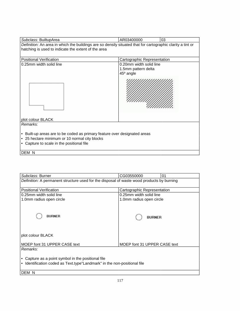
117
Subclass: BuiltupArea AR03400000 03Definition: An area in which the buildings are so densily situated that for cartographic clarity a tint orhatching is used to indicate the extent of the area
Positional Verification Cartographic Representation0.25mm width solid line 0.20mm width solid line
1.5mm pattern delta45º angle
plot colour BLACKRemarks:
• Built-up areas are to be coded as primary feature over designated areas• 25 hectare minimum or 10 normal city blocks• Capture to scale in the positional file
DEM N
Subclass: Burner CG03550000 01Definition: A permanent structure used for the disposal of waste wood products by burning
Positional Verification Cartographic Representation0.25mm width solid line 0.25mm width solid line1.0mm radius open circle 1.0mm radius open circle
plot colour BLACK
MOEP font 31 UPPER CASE text MOEP font 31 UPPER CASE textRemarks:
• Capture as a point symbol in the positional file• Identification coded as Text.type"Landmark" in the non-positional file
DEM N

118

119
C
Subclass: Cable EA03800000 02Definition: An insulated wire used for conducting an electrical current, e.g., television, telephone, orsubmarine telegraph or telephone
Positional Verification Cartographic Representation0.25mm width line 0.20mm width solid line
3.0mm dash 5.0mm dash
1.5mm between dashes 1.0mm between dashes
plot colour BLACK MOEP font 31 UPPER CASE textRemarks:
• 100m. minimum• Captured to scale in the positional file• Identification coded as Text.type"Landmark" in the non-positional file
DEM N

120
Subclass: CadastralPoint.status"PermanentlyMarked" FD90500000 01Definition: A marked point, surveyed or derived, of known geographic coordinates.
Positional Verification Cartographic Representation0.25mm width solid line 0.35mm width solid line
2.0mm line length each side of diamond
0.25mm diameter dot
plot colour BLACK MOEP font 31 UPPER CASE textRemarks:
• Placed in the non-positional file
DEM N
Subclass: CampgroundCampsite AL03900000 02/03Definition: A parcel or tract of land developed for tents and/or trailers to serve as temporary residencesfor the public.
Positional Verification Cartographic Representation3.0mm dash 3.0mm dash1.5mm between dashes 1.5mm between dashes
plot colour BLACK MOEP font 31 UPPER CASE textRemarks:
• 1 hectare minimum• Capture to scale in the opsitional file• Identification coded as Text.type "Landmark" in the non-positional file
DEM N
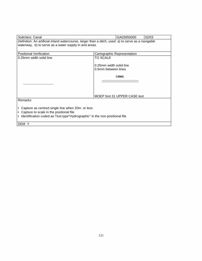
121
Subclass: Canal GA03950000 02/03Definition: An artificial inland watercourse, larger than a ditch, used: a) to serve as a navigablewaterway, b) to serve as a water supply in arid areas.
Positional Verification Cartographic Representation0.25mm width solid line TO SCALE
0.25mm width solid line0.5mm between lines
MOEP font 31 UPPER CASE textRemarks:
• Capture as centred single line when 20m. or less• Capture to scale in the positional file• Identification coded as Text.type"Hydrographic" in the non-positional file
DEM Y
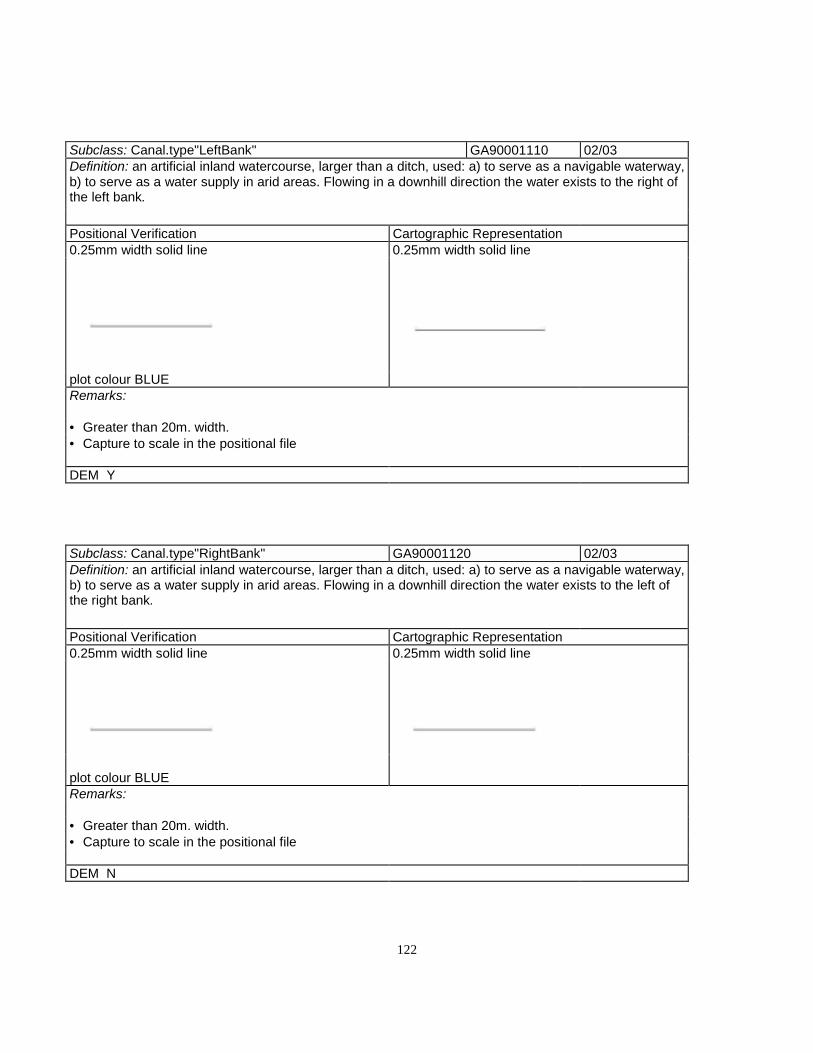
122
Subclass: Canal.type"LeftBank" GA90001110 02/03Definition: an artificial inland watercourse, larger than a ditch, used: a) to serve as a navigable waterway,b) to serve as a water supply in arid areas. Flowing in a downhill direction the water exists to the right ofthe left bank.
Positional Verification Cartographic Representation0.25mm width solid line 0.25mm width solid line
plot colour BLUERemarks:
• Greater than 20m. width.• Capture to scale in the positional file
DEM Y
Subclass: Canal.type"RightBank" GA90001120 02/03Definition: an artificial inland watercourse, larger than a ditch, used: a) to serve as a navigable waterway,b) to serve as a water supply in arid areas. Flowing in a downhill direction the water exists to the left ofthe right bank.
Positional Verification Cartographic Representation0.25mm width solid line 0.25mm width solid line
plot colour BLUERemarks:
• Greater than 20m. width.• Capture to scale in the positional file
DEM N

123
Subclass: Cemetary AM04560000 02/03Definition: A burial place or burial ground
Positional Verification Cartographic Representation0.25mm width line 0.35mm width solid line
plot colour BLACK MOEP font 31 UPPER CASE textRemarks:
• 1 hectare minimum• Capture to scale in the opsitional file• Identification coded as Text.type "Landmark" in the non-positional file
DEM N

124
Subclass: Church (to scale) BM05300000 02
(symbolized) BM91100000 01Definition: Church, Mosque, Synagogue, Temple - A building of worship.
Positional Verification Cartographic RepresentationTO SCALE SYMBOLIZED TO SCALE SYMBOLIZED
0.25mm width solid line 0.25mm width solid line 0.25mm width solid line 0.25mm width solid line
0.8mm open square 0.8mm filled square
plot colour BLACK MOEP font 31 UPPERCASE text
MOEP font 31 UPPER CASEtextRemarks:
• Capture to scale in the positional file using the right hand rule when one side is > 30m. or the total area is >900 sq. m.• Capture as a point in the positional file oriented to the true ground position when total area is < 900 sq. m.with no sides > 30m.• Determine building dimensions by the outline of the roofs, including attached garages and multilevel parking.Place building type identification as generic text, size determined by building size.
DEM N

125
Subclass: CityHall (to scale) BF05550000 02
(symbolized) BF91200000 01Definition: The chief administrative building of a city.
Positional Verification Cartographic RepresentationTO SCALE SYMBOLIZED TO SCALE SYMBOLIZED
0.25mm width solid line 0.25mm width solid line 0.25mm width solid line 0.25mm width solidline
0.8mm open square 0.8mm filled square
plot colour BLACK
Remarks:
• Capture to scale in the positional file using the right hand rule when one side is > 30m. or the total area is >900 sq. m.• Capture as a point in the positional file oriented to the true ground position when total area is < 900 sq. m. withno sides > 30m.• Determine building dimensions by the outline of the roofs, including attached garages and multilevel parking.
DEM N

126
Subclass: Cliff/Scarp HB05650000 03Definition: 1) A cliff is a perpindicular or nearly perpindicular rock face 2) A scarp is a line of cliffsPositional Verification Cartographic Representation0.25mm width solid line 0.25mm width solid line
variable tick length1.5mm between ticks
plot colour PURPLE MOEP font 31 UPPER CASE textRemarks:
• Capture only sterio dead zones due to vertical relief• Capture to scale in the positional file• Identification coded as Text.type"Landform" in the non-positional file
DEM Y
Subclass: CoastlineGeometric representation Qualifier: Definite
GG05800000 03
Definition: The shoreline of an ocean at high water mark.
Positional Verification Cartographic Representation0.25mm width solid line 0.35mm width solid line
plot colour PURPLERemarks:
• Capture in the positional file with land to the right• Tidal high water mark that is visible on the aerial photography• The apparent high water mark of body of water is where the presence and action of the water are socommon odn usual as to mark on the soil of the bed of the body of water a character distinct from that ofits banks, in vegetation and in the nature of the soil itself.
DEM Y
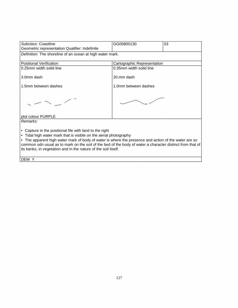
127
Subclass: CoastlineGeometric representation Qualifier: Indefinite
GG05800130 03
Definition: The shoreline of an ocean at high water mark.
Positional Verification Cartographic Representation0.25mm width solid line 0.35mm width solid line
3.0mm dash 20.mm dash
1.5mm between dashes 1.0mm between dashes
plot colour PURPLERemarks:
• Capture in the positional file with land to the right• Tidal high water mark that is visible on the aerial photography• The apparent high water mark of body of water is where the presence and action of the water are socommon odn usual as to mark on the soil of the bed of the body of water a character distinct from that ofits banks, in vegetation and in the nature of the soil itself.
DEM Y

128
Subclass: College (to scale) BE05900000 02
(symbolized) BE90800000 03Definition: An institution for post-secondary instruction in a professional, vocational, or technical field.
Positional Verification CartographicRepresentation
TO SCALE SYMBOLIZED TO SCALE SYMBOLIZED
0.25mm width solid line 0.25mm width solid line 0.25mm width solid line 0.25mm width solidline
0.8mm open square 0.8mm filled square
plot colour BLACK MOEP font 31 UPPERCASE text
MOEP font 31 UPPER CASE textRemarks:
• Capture to scale in the positional file using the right hand rule when one side is > 30m. or the total area is >900 sq. m.• Capture as a point in the positional file oriented to the true ground position when total area is < 900 sq. m.with no sides > 30m.• Determine building dimensions by the outline of the roofs, including attached garages and multilevel parking.Place building type identification as Text.type"Landmark", size determined by building size.
DEM N
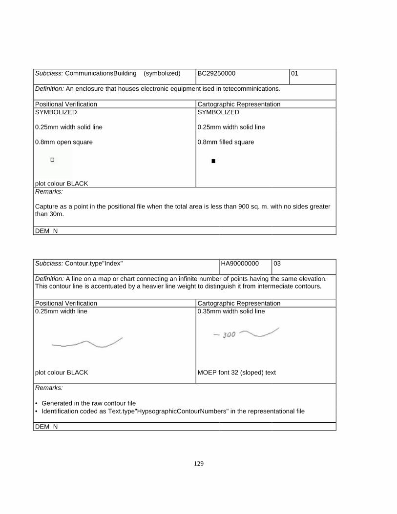
129
Subclass: CommunicationsBuilding (symbolized) BC29250000 01
Definition: An enclosure that houses electronic equipment ised in tetecomminications.
Positional Verification Cartographic RepresentationSYMBOLIZED SYMBOLIZED
0.25mm width solid line 0.25mm width solid line
0.8mm open square 0.8mm filled square
plot colour BLACKRemarks:
Capture as a point in the positional file when the total area is less than 900 sq. m. with no sides greaterthan 30m.
DEM N
Subclass: Contour.type"Index" HA90000000 03
Definition: A line on a map or chart connecting an infinite number of points having the same elevation.This contour line is accentuated by a heavier line weight to distinguish it from intermediate contours.
Positional Verification Cartographic Representation0.25mm width line 0.35mm width solid line
plot colour BLACK MOEP font 32 (sloped) text
Remarks:
• Generated in the raw contour file• Identification coded as Text.type"HypsographicContourNumbers" in the representational file
DEM N
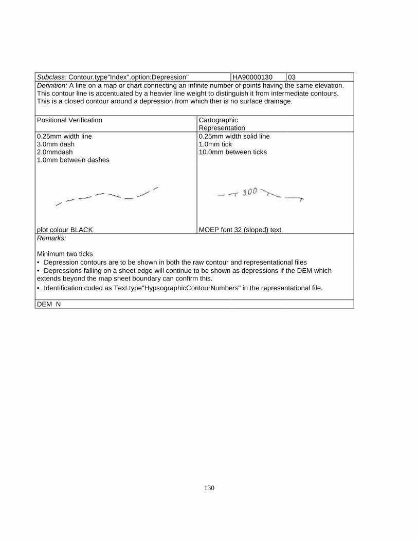
130
Subclass: Contour.type"Index".option:Depression" HA90000130 03Definition: A line on a map or chart connecting an infinite number of points having the same elevation.This contour line is accentuated by a heavier line weight to distinguish it from intermediate contours.This is a closed contour around a depression from which ther is no surface drainage.
Positional Verification CartographicRepresentation
0.25mm width line 0.25mm width solid line3.0mm dash 1.0mm tick2.0mmdash 10.0mm between ticks1.0mm between dashes
plot colour BLACK MOEP font 32 (sloped) textRemarks:
Minimum two ticks• Depression contours are to be shown in both the raw contour and representational files• Depressions falling on a sheet edge will continue to be shown as depressions if the DEM whichextends beyond the map sheet boundary can confirm this.• Identification coded as Text.type"HypsographicContourNumbers" in the representational file.
DEM N
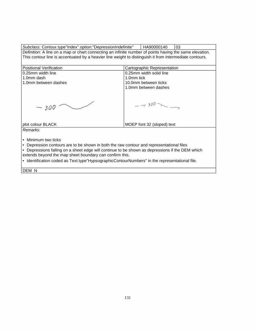
131
Subclass: Contour.type"Index".option:"DepressionIndefinite" HA90000140 03Definition: A line on a map or chart connecting an infinite number of points having the same elevation.This contour line is accentuated by a heavier line weight to distinguish it from intermediate contours.
Positional Verification Cartographic Representation0.25mm width line 0.25mm width solid line1.0mm dash 1.0mm tick1.0mm between dashes 10.0mm between ticks
1.0mm between dashes
plot colour BLACK MOEP font 32 (sloped) textRemarks:
• Minimum two ticks• Depression contours are to be shown in both the raw contour and representational files• Depressions falling on a sheet edge will continue to be shown as depressions if the DEM whichextends beyond the map sheet boundary can confirm this.• Identification coded as Text.type"HypsographicContourNumbers" in the representational file.
DEM N

132
Subclass: Contour.type"Index".option:"Indefinite" HA90000110 03Definition: A line on a map or chart connecting an infinite number of points having the same elevation.This contour line is accentuated by a heavier line weight to distinguish it from intermediate contours.
Positional Verification CartographicRepresentation
0.25mm width line 0.25mm width line3.0mm dash 20.0mm dash1.5mm between dashes 10.0mm between dashes
plot colour BLACK MOEP font 32 (sloped) textRemarks:
• Generated in the raw contour file• Identification coded as Text.type"HypsographicContourNumbers" in the representational file
DEM N
Subclass: Contour.type"Intermediate" HA90001000 03Definition: A line on a map or chart connecting an infinite number of points having the same elevation.This contour is drawn between index contours.
Positional Verification Cartographic Representation0.25mm width solid line 0.20mm width solid line
plot colour BROWNRemarks:
• Generated in the raw contour file
DEM N

133
Subclass:Contour.type"Intermediate".option:"Depression"
HA90001130 03
Definition: A line on a map or chart connecting an infinite number of points having the same elevation.This contour is drawn between index contours.
Positional Verification Cartographic Representation0.25mm width line 0.20mm width solid line3.0mm dash 1.0mm tick2.0mm dash 10.0mm between ticks1.0mm between dashes
plot colour BROWNRemarks:
• Minimum two ticks• Depression contours are to be shown in both the raw contour and representational files• Depressions falling on a sheet edge will continue to be shown as depressions if the DEM whichextends beyond the map sheet boundary can confirm this.
DEM N
Subclass:Contour.type"Intermediate".option:"DepressionIndefinite"
HA90001140 03
Definition: A line on a map or chart connecting an infinite number of points having the same elevation.This contour is drawn between index contours.
Positional Verification Cartographic Representation0.25mm width line 0.20mm width solid line1.0mm dash 1.0mm tick1.0mm between dashes 10.0mm between ticks
20.0mm dash
plot colour BROWN 1.0mm between dashesRemarks:
• Minimum two ticks• Depression contours are to be shown in both the raw contour and representational files• Depressions falling on a sheet edge will continue to be shown as depressions if the DEM whichextends beyond the map sheet boundary can confirm this.
DEM N

134
Subclass: Contour.type"Intermediate".option:"Indefinite" HA90001110 03Definition: A line on a map or chart connecting an infinite number of points having the same elevation.This contour is drawn between index contours.
Positional Verification Cartographic Representation0.25mm width line 0.20mm width solid line3.0mm dash 20.0mm between ticks1.5mm between dashes 1.0mm between dashes
plot colour BROWNRemarks:
• Generated in the raw contour file
DEM N
Subclass:ControlPoint.type"Horizontal".status"PerminanentlyMarked"
FB18450000 01
Definition: A surveyed and marked point of known latitudes and longitude. (may include elevation)
Positional Verification Cartographic Representation0.25mm width line 0.25mm width lineTriangle 4.0mm on each side Triangle 2.0mm on each side0.5mm dot in centre 0.5mm dot in centre
plot colour BLACK
1.8mm MOEP font 31 UPPER CASE text MOEP font 31 UPPER CASE textRemarks:
• Capture in the positional file• Identification coded as Text.type"AerialTriangulation" in the non-positional file
DEM Y

135
Subclass:ControlPoint.type"Vertical".status"PerminanentlyMarked"
FB18650000 01
Definition: A surveyed and marked point of known elevation.
Positional Verification Cartographic Representation0.25mm width line 0.25mm width line2.5mm diameter open circle 2.5mm diameter open circle0.5mm dot 0.5mm dot
plot colour BLACK MOEP font 31 text
1.5mm MOEP font 31 textRemarks:
• Capture in the positional file• Identification coded as Text.type"AerialTriangulation" in the non-positional file
DEM Y
Subclass:Conveyor CQ06400000 02/03
Definition: A mechanical apparatus used to carry materials by means of a moving belt.
Positional Verification Cartographic Representation0.25mm width solidline 0.35mm width solid line
plot colour BLACK MOEP font 31 UPPER CASE textRemarks:
• Capture to scale in the positional file• Identification coded as Text.type"Landmark" in the non-positional file
DEM N

136
Subclass: Courthouse (to scale) BF07550000 02
(symbolized) BF91300000 01Definition: A building in which courts of law are regularly convened.
Positional Verification Cartographic RepresentationTO SCALE SYMBOLIZED TO SCALE SYMBOLIZED
0.25mm width solid line 0.25mm width solid line 0.25mm width solid line 0.25mm width solid line
0.8mm open square 0.8mm filled square
plot colour BLACK
Remarks:
• Capture to scale in the positional file using the right hand rule when any one side is >30m or the total area is>900 sq. m.• Capture as a point in the positional file oriented to the true ground position when total area is<900 sq. m. with nosides >30m• Determine building dimension by the outline of their roofs, including attached garages and multilevel larking.
DEM N
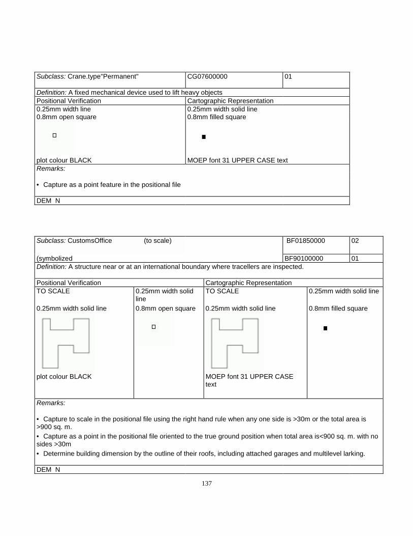
137
Subclass: Crane.type"Permanent" CG07600000 01
Definition: A fixed mechanical device used to lift heavy objectsPositional Verification Cartographic Representation0.25mm width line 0.25mm width solid line0.8mm open square 0.8mm filled square
plot colour BLACK MOEP font 31 UPPER CASE textRemarks:
• Capture as a point feature in the positional file
DEM N
Subclass: CustomsOffice (to scale) BF01850000 02
(symbolized BF90100000 01Definition: A structure near or at an international boundary where tracellers are inspected.
Positional Verification Cartographic RepresentationTO SCALE 0.25mm width solid
lineTO SCALE 0.25mm width solid line
0.25mm width solid line 0.8mm open square 0.25mm width solid line 0.8mm filled square
plot colour BLACK MOEP font 31 UPPER CASEtext
Remarks:
• Capture to scale in the positional file using the right hand rule when any one side is >30m or the total area is>900 sq. m.• Capture as a point in the positional file oriented to the true ground position when total area is<900 sq. m. with nosides >30m• Determine building dimension by the outline of their roofs, including attached garages and multilevel larking.
DEM N

138
Subclass: CutEarthwork DD08350000 02/03Definition: A surface excavation made so that a uniform grade can be maintained on a road or railway.
Positional Verification Cartographic Representation0.25mm width solid line 0.20mm width solid line
1.25mm ticks 1.5mm between ticks
plot colour REDRemarks:
• 400m. minimum• 20m. vertical accuracy• Capture in the positional file
DEM Y
Subclass: CutLineSeismicLine JA08400000 02/03Definition: A line cut through a forest area to facilitate a cadastral or seismic survey or to create afirebreak
Positional Verification Cartographic Representation0.25mm width line 0.25mm width solid line
1.0mm dash 2.0mm dash
1.0mm between dashes
1.0mm between dashesplot colour BLACKRemarks:
• 400m. minimum• 20m. vertical accuracy• Capture in the positional file
DEM N

139
D
Subclass: Dam (symbolized) GA98450000 01Definition: A barrier built across a watercourse or waterbody to control the water flow.
Positional Verification Cartographic RepresentationSYMBOLIZED SYMBOLIZED
0.25mm width solid line 0.50mm width solid line
6.0mm line
0.5mm tick
plot colour BLACK MOEP font 31 UPPER CASE text
Remarks:
• 100m. length maximum data point captured at centre of dam in positional file• see Part II 2.3.2 Additional Remarks - Hydrographic and Related Features• Identification coded as Text.type"Hydrographic" in the non-positional file
DEM N

140
Subclass: DamSection"Base" GA98450100 02/03Definition: A barrier built across watercourse or waterbody to control water flow. The base is the lowerpart, bottom, or foundation of the dam.
Positional Verification Cartographic Representation0.25mm width solid line 0.25mm width solid line
plot colour BLACK MOEP font 31 UPPER CASE textRemarks:
• Major dams only• Capture dam base when visible• Capture as closed polygon in the positional file• Include the coincident lake construction line in the DEM as a primary hydrographic breakline• see Part II 2.3.2 Additional Remarks - Hydrographic and Related Features• Identification coded as Text.type"Hydrographic" in the non-positional file
DEM N

141
Subclass:Dam.section"Spillway/Penstock" GA28550000 02/03Definition: A barrier built across watercourse or waterbody to control water flow. A spillway is a passageallowing surplus water to run over or around an obstruction such as a dam. A penstock is a conduit thatcarries water to the turbine in a power generating station.
Positional Verification Cartographic Representation0.25mm width solid line 0.50mm width solid line
plot colour BLACK MOEP font 31 UPPER CASE textRemarks:
• 100m. minimum length• If under 20m. width capture as single line in the positional file• If over 20m. in width capture as closed polygon in the positional file• see Part II 2.3.2 Additional Remarks - Hydrographic and Related Features• Identification coded as Text.type"Hydrographic" in the non-positional file
DEM N

142
Subclass: Dam.section"Top" GA08450000 02/03Definition: A barrier built across watercourse or waterbody to control water flow. When captured toscale, the area located at the top of the dam.
Positional Verification Cartographic RepresentationTO SCALE TO SCALE
0.25mm width solid line 0.50mm width solid line
plot colour BLACK MOEP font 31 UPPER CASE textRemarks:
• 100m. length minimum closed polygon captured in the positional file• see Part II 2.3.2 Additional Remarks - Hydrographic and Related Features• Identification coded as Text.type"Hydrographic" in the non-positional file
DEM N
Subclass: DEMPoint.type"Definite" HA90100000 01Definition: A point collected photogrammetrically from a stationary measuring device and capturedspecifically to represent the topographic surface shape in explicit x, y and z values.
Positional Verification Cartographic Representation0.25mm width solid line
^
plot colour BLACKRemarks:
• Capture as a point feature in the DEM file• Not included in the representational file
DEM Y
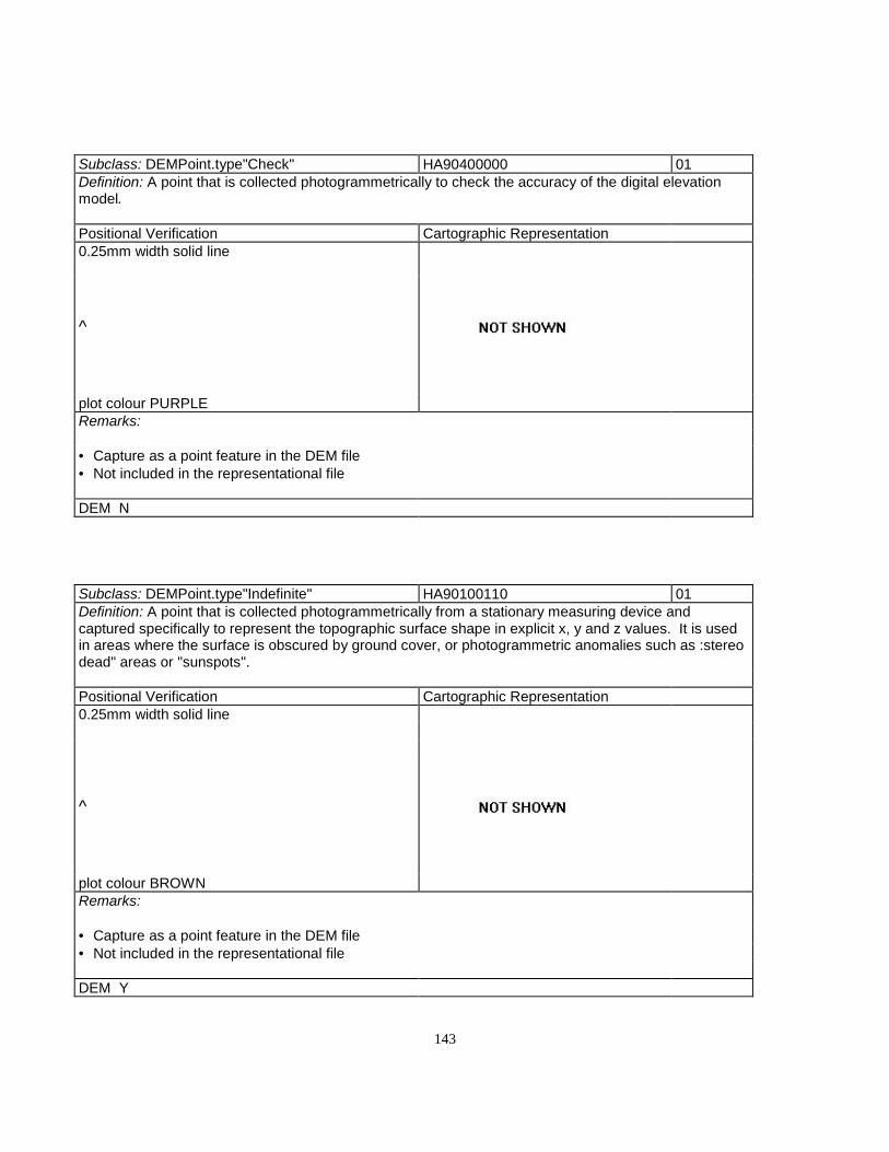
143
Subclass: DEMPoint.type"Check" HA90400000 01Definition: A point that is collected photogrammetrically to check the accuracy of the digital elevationmodel.
Positional Verification Cartographic Representation0.25mm width solid line
^
plot colour PURPLERemarks:
• Capture as a point feature in the DEM file• Not included in the representational file
DEM N
Subclass: DEMPoint.type"Indefinite" HA90100110 01Definition: A point that is collected photogrammetrically from a stationary measuring device andcaptured specifically to represent the topographic surface shape in explicit x, y and z values. It is usedin areas where the surface is obscured by ground cover, or photogrammetric anomalies such as :stereodead" areas or "sunspots".
Positional Verification Cartographic Representation0.25mm width solid line
^
plot colour BROWNRemarks:
• Capture as a point feature in the DEM file• Not included in the representational file
DEM Y

144
Subclass: DEMPoint.type"Interpolated" HA90300000 01Definition: An unsampled spotheight, explicit in x, y and z, generated arithmetically from the values ofsurrounding directly sampled points.
Positional Verification Cartographic Representation0.25mm width solid line
^
plot colour REDRemarks:
• Capture as a point feature in the DEM file
• Not included in the representational file
DEM Y
Subclass: DesignatedArea AS90000000 02/03Definition: An area dedicated to a particular use or purpose.
Positional Verification Cartographic Representation0.25mm width line 0.25mm width line3.0mm dash 3.0mm dash1.5mm between dashes 1.5mm between dashes
plot colour BLACK MOEP font 31 UPPER CASE textRemarks:
• 1 hectare minimum• Captured to scale in the positional file• Identification coded as Text.type"Landmark" in the non-positional file• For hierarchy see Part II Section 2.3.5(j)
DEM N

145
Subclass: Ditch GA08800110 02/03Definition: A man-made trench in the earth used for drainage or irrigation.
Positional Verification Cartographic Representation0.25mm width solid line 0.25mm width solid line
plot colour BLUERemarks:
• This feature must be continuous over 200m• Ditches shall be captured if they form part of the main drainage system• Captured in the positional file
DEM Y
Subclass: DriveinTheatre AL09000000 02/03Definition: An open air facility which allows patrons to view motion pictures while seated in vehicles
Positional Verification Cartographic Representation0.25mm width line 0.25mm width line
3.0mm dash 3.0mm dash
1.5mm between dashes 1.5mm between dashes
plot colour BLACK MOEP font 31 UPPER CASE textRemarks:
1 hectare minimumCaptured to scale in the positional fileIdentification coded as Text.type"Landmark" in the non-positional file
DEM N

146
Subclass: DrivingRange AL23300120 02/03Definition: A facility for practising the driving of golfballs.
Positional Verification Cartographic Representation0.25mm width line 0.25mm width line
3.0mm dash 3.0mm dash
1.5mm between dashes 1.5mm between dashes
plot colour BLACK MOEP font 31 UPPER CASE textRemarks:
• 1 hectare minimum• Captured to scale in the positional file• Identification coded as Text.type"Landmark" in the non-positional file
DEM N
Subclass: DryDock CG09100000 02/03Definition: An enclosure from which the water can be removed to facilitate the repair and maintenanceof ships
Positional Verification Cartographic Representation0.25mm width solid line 0.25mm width solid line
plot colour BLACKRemarks:
• Minimum length 50 metres• Captured in the opsitional file as a closed polygon when over 20 metres in width
DEM N

147

148
Subclass: Dump AP09200000 02/03Definition: An area set aside for the disposal of garbage and other refuse.
Positional Verification Cartographic Representation0.25mm width line 0.25mm width line3.0mm dash 3.0mm dash1.5mm between dashes 1.5mm between dashes
plot colour BLACK MOEP font 31 UPPER CASE textRemarks:
• 1 hectare minimum• Captured to scale in the opsitional file• Identification coded as Text.type"Landmark" in the non-positional file
DEM N
Subclass: Dyke GE09400000 02/03Definition: An embankment built to restrict the flowof water or other liquids.
Positional Verification Cartographic Representation0.25mm width solid line 0.25mm width solid line
1.0mm ticks
1.5mm between ticks
plot colour BROWN MOEP font 31 UPPER CASE textRemarks:
• 100m minimum• Line - high side• Ticks - low side• Low side is right side• Width 50m. or greater, capture in the positional file to scale as closed polygon and show symbol onboth sides• Identification coded as Text.type"Hydrographic" in the non-positional file
DEM Y
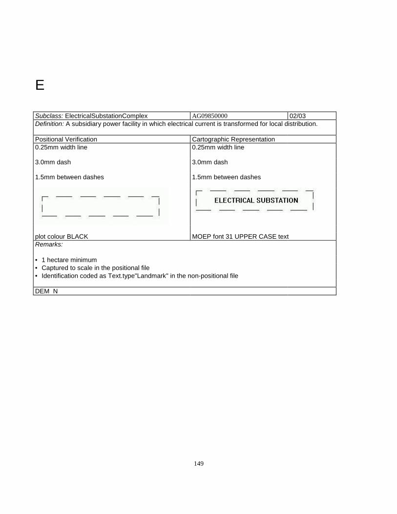
149
E
Subclass: ElectricalSubstationComplex AG09850000 02/03Definition: A subsidiary power facility in which electrical current is transformed for local distribution.
Positional Verification Cartographic Representation0.25mm width line 0.25mm width line
3.0mm dash 3.0mm dash
1.5mm between dashes 1.5mm between dashes
plot colour BLACK MOEP font 31 UPPER CASE textRemarks:
• 1 hectare minimum• Captured to scale in the positional file• Identification coded as Text.type"Landmark" in the non-positional file
DEM N
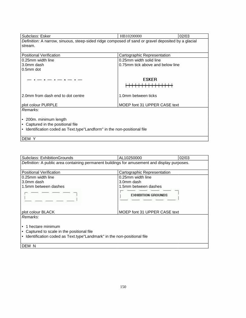
150
Subclass: Esker HB10200000 02/03Definition: A narrow, sinuous, steep-sided ridge composed of sand or gravel deposited by a glacialstream.
Positional Verification Cartographic Representation0.25mm width line 0.25mm width solid line3.0mm dash 0.75mm tick above and below line0.5mm dot
2.0mm from dash end to dot centre 1.0mm between ticks
plot colour PURPLE MOEP font 31 UPPER CASE textRemarks:
• 200m. minimum length• Captured in the positional file• Identification coded as Text.type"Landform" in the non-positional file
DEM Y
Subclass: ExhibitionGrounds AL10250000 02/03Definition: A public area containing permanent buildings for amusement and display purposes.
Positional Verification Cartographic Representation0.25mm width line 0.25mm width line3.0mm dash 3.0mm dash1.5mm between dashes 1.5mm between dashes
plot colour BLACK MOEP font 31 UPPER CASE textRemarks:
• 1 hectare minimum• Captured to scale in the positional file• Identification coded as Text.type"Landmark" in the non-positional file
DEM N
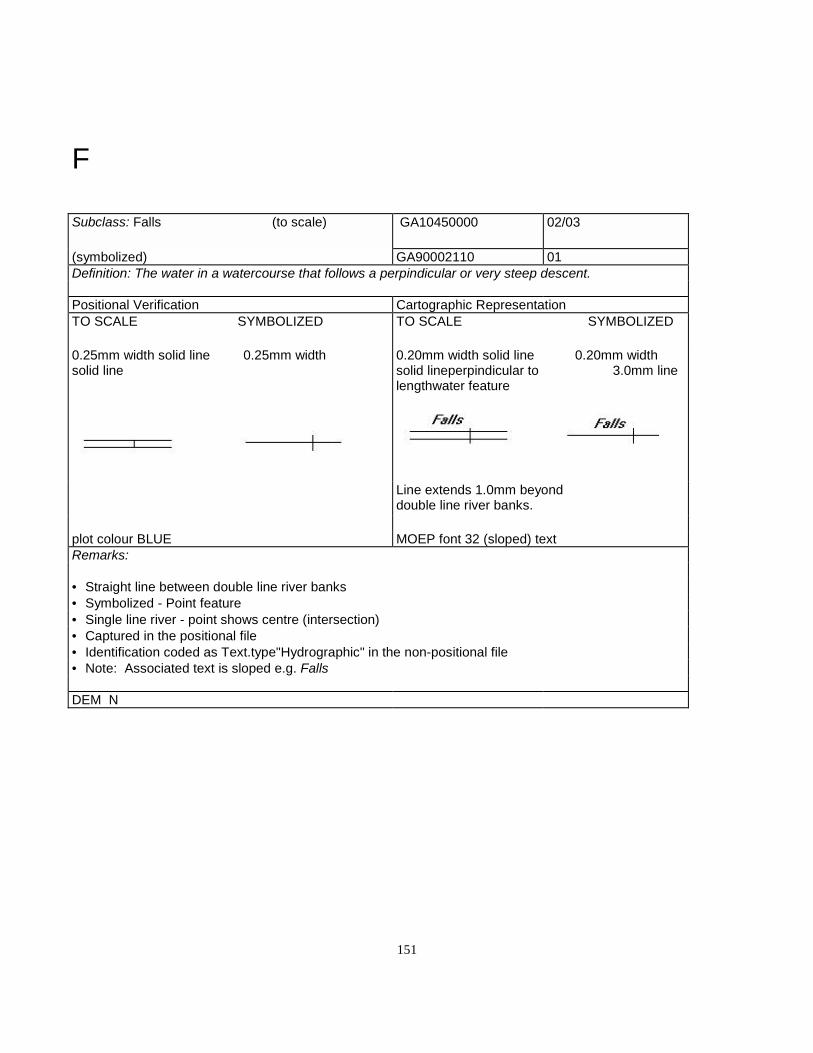
151
F
Subclass: Falls (to scale) GA10450000 02/03
(symbolized) GA90002110 01Definition: The water in a watercourse that follows a perpindicular or very steep descent.
Positional Verification Cartographic RepresentationTO SCALE SYMBOLIZED TO SCALE SYMBOLIZED
0.25mm width solid line 0.25mm widthsolid line
0.20mm width solid line 0.20mm widthsolid lineperpindicular to 3.0mm linelengthwater feature
Line extends 1.0mm beyonddouble line river banks.
plot colour BLUE MOEP font 32 (sloped) textRemarks:
• Straight line between double line river banks• Symbolized - Point feature• Single line river - point shows centre (intersection)• Captured in the positional file• Identification coded as Text.type"Hydrographic" in the non-positional file• Note: Associated text is sloped e.g. Falls
DEM N
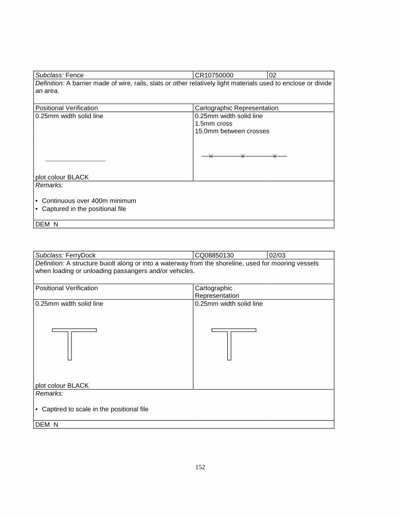
152
Subclass: Fence CR10750000 02Definition: A barrier made of wire, rails, slats or other relatively light materials used to enclose or dividean area.
Positional Verification Cartographic Representation0.25mm width solid line 0.25mm width solid line
1.5mm cross15.0mm between crosses
plot colour BLACKRemarks:
• Continuous over 400m minimum• Captured in the positional file
DEM N
Subclass: FerryDock CQ08850130 02/03Definition: A structure buiolt along or into a waterway from the shoreline, used for mooring vesselswhen loading or unloading passangers and/or vehicles.
Positional Verification CartographicRepresentation
0.25mm width solid line 0.25mm width solid line
plot colour BLACKRemarks:
• Captired to scale in the positional file
DEM N

153
Subclass: FerryRoute AQ10800000 02Definition: The water route a ferry follows when transporting vehicles and /or passangers.
Positional Verification CartographicRepresentation
0.25mm width line 0.25mm width line0.3mm dash1.5mm between dashes
plot colour RED MOEP font 31 UPPER CASE textRemarks:
• Captured to scale in the positional file• minimum distance 10km.• Identification cided as Text.type"Transportation" in the non-positional file
DEM N
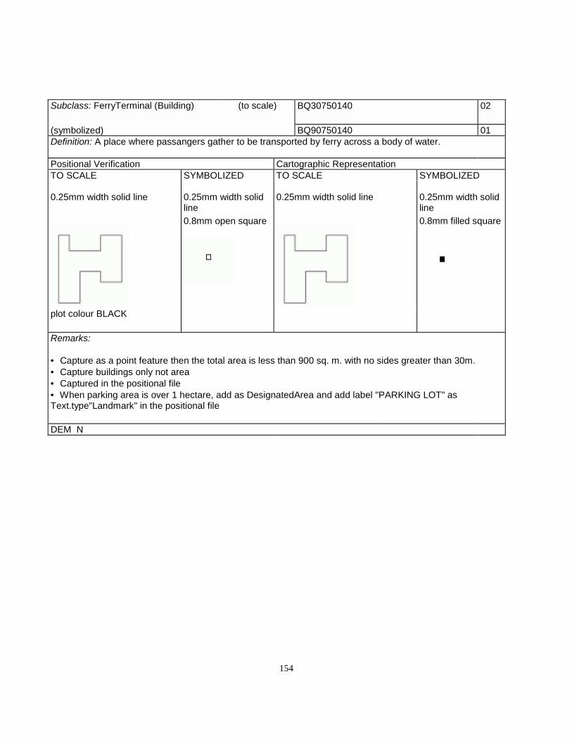
154
Subclass: FerryTerminal (Building) (to scale) BQ30750140 02
(symbolized) BQ90750140 01Definition: A place where passangers gather to be transported by ferry across a body of water.
Positional Verification Cartographic RepresentationTO SCALE SYMBOLIZED TO SCALE SYMBOLIZED
0.25mm width solid line 0.25mm width solidline
0.25mm width solid line 0.25mm width solidline
0.8mm open square 0.8mm filled square
plot colour BLACK
Remarks:
• Capture as a point feature then the total area is less than 900 sq. m. with no sides greater than 30m.• Capture buildings only not area• Captured in the positional file• When parking area is over 1 hectare, add as DesignatedArea and add label "PARKING LOT" asText.type"Landmark" in the positional file
DEM N

155
Subclass: FillEmbankment DD09950000 02/03Definition: A portion of a road or railway that has been built-up with earth or other materials to maintaina uniform grade.
Positional Verification Cartographic Representation0.25mm width solid line 0.25mm width solid line
1.25mm width solid line1.5mm between ticks
plot colour BROWN
Remarks:
• 100m. length minimum• Not a closed polygon• Line-high side• Ticks-low side (right side)• Captured in the positional file
DEM Y
Subclass: FireLookoutTower BF10950120 01Definition: A high structure from which the outbreak of forest fires can be detected and reported.
Positional Verification Cartographic Representation0.25mm width line 0.25mm width line2.0mm square 2.0mm square
plot colour BLACKRemarks:
• When over 30 metres tall, height is captured as an attribute (MOEP type 05)• Captured as a point feature in the positional file• Identification coded as Text.type"Landmark" in the non-positional file
DEM N
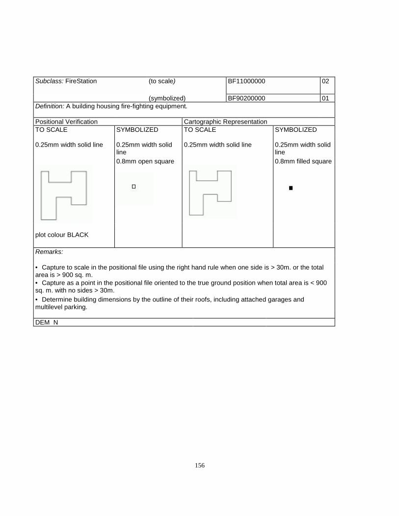
156
Subclass: FireStation (to scale) BF11000000 02
(symbolized) BF90200000 01Definition: A building housing fire-fighting equipment.
Positional Verification Cartographic RepresentationTO SCALE SYMBOLIZED TO SCALE SYMBOLIZED
0.25mm width solid line 0.25mm width solidline
0.25mm width solid line 0.25mm width solidline
0.8mm open square 0.8mm filled square
plot colour BLACK
Remarks:
• Capture to scale in the positional file using the right hand rule when one side is > 30m. or the totalarea is > 900 sq. m.• Capture as a point in the positional file oriented to the true ground position when total area is < 900sq. m. with no sides > 30m.• Determine building dimensions by the outline of their roofs, including attached garages andmultilevel parking.
DEM N

157
Subclass: FishHatchery AF11150000 02/03Definition: A facility used for the spawning of fish.
Positional Verification Cartographic Representation0.25mm width line 0.20mm width line3.0mm dash 3.0mm dash1.5mm between dashes 1.5mm between dashes
plot colour BLACK MOEP font 31 UPPER CASE textRemarks:
• 1 hectare minimum• Captured to scale in the positional file• Identification coded as Text.type"Landmark" in the non-positional file
DEM N
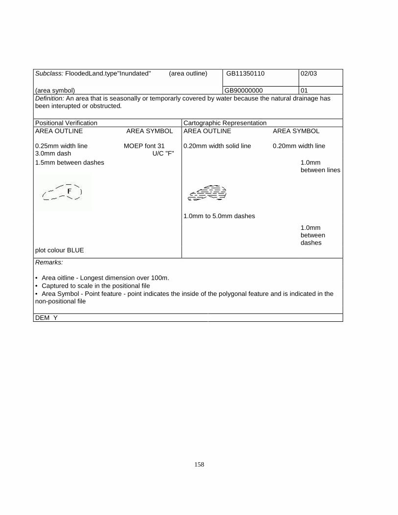
158
Subclass: FloodedLand.type"Inundated" (area outline) GB11350110 02/03
(area symbol) GB90000000 01Definition: An area that is seasonally or temporarly covered by water because the natural drainage hasbeen interupted or obstructed.
Positional Verification Cartographic RepresentationAREA OUTLINE AREA SYMBOL AREA OUTLINE AREA SYMBOL
0.25mm width line MOEP font 313.0mm dash U/C "F"
0.20mm width solid line 0.20mm width line
1.5mm between dashes 1.0mmbetween lines
1.0mm to 5.0mm dashes
1.0mmbetweendashes
plot colour BLUE
Remarks:
• Area oitline - Longest dimension over 100m.• Captured to scale in the positional file• Area Symbol - Point feature - point indicates the inside of the polygonal feature and is indicated in thenon-positional file
DEM Y

159
Subclass: FlowArrow GE90200000 01/02Definition: A symbol used to clarify the direction of flow on a double line stream when the information isnot evident from the map relief.
Positional Verification Cartographic Representation0.25mm width solid line 0.25mm width solid line
3.0mm filled head and tail
plot colour BLUE MOEP font 31 UPPER CASE textRemarks:
• Used to clarify flow direction on rivers• NOTE: This feature is shown on the verification plot and representational hard copy onlyIt is coded in the non-positional file• Although depicted on the verification plot this feature is NOT INCLUDED in the positional file
DEM N
Subclass: Flume GA11500000 02/03Definition: An inclined, man-made, open channel used to convey water for other than drainagepurposes.
Positional Verification Cartographic Representation0.25mm width solid line 0.25mm width solid line
2.0mm symbol15.0mm between symbols
symbol is made up of a 0.6mm straight line with a0.7mm 45º angled line at each end
plot colour BLACKRemarks:
• Minimum length 100 metres• Captured in the positional file
DEM N
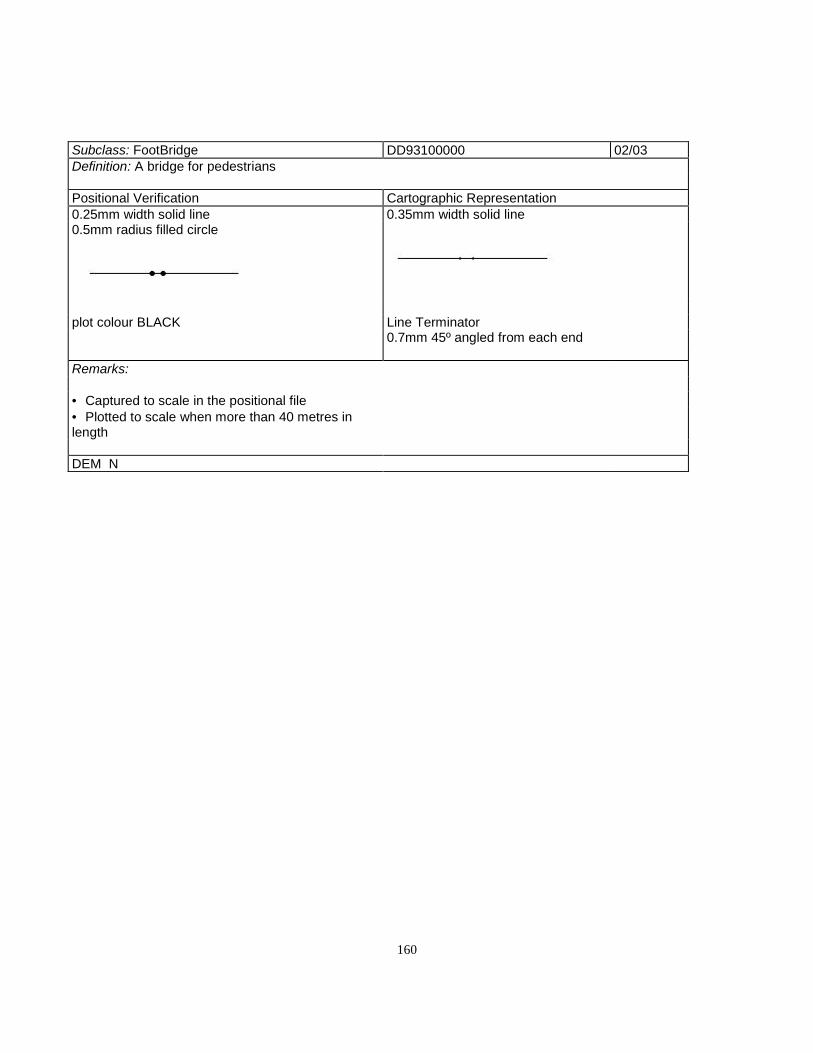
160
Subclass: FootBridge DD93100000 02/03Definition: A bridge for pedestrians
Positional Verification Cartographic Representation0.25mm width solid line 0.35mm width solid line0.5mm radius filled circle
plot colour BLACK Line Terminator0.7mm 45º angled from each end
Remarks:
• Captured to scale in the positional file• Plotted to scale when more than 40 metres inlength
DEM N
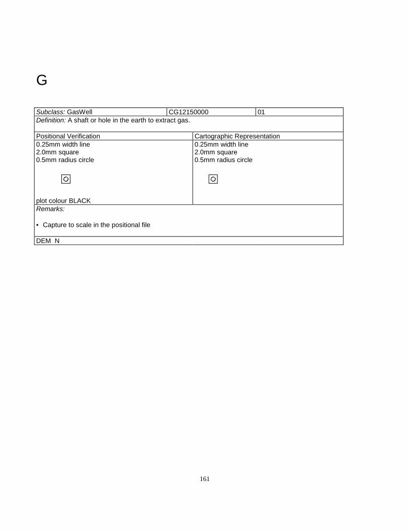
161
G
Subclass: GasWell CG12150000 01Definition: A shaft or hole in the earth to extract gas.
Positional Verification Cartographic Representation0.25mm width line 0.25mm width line2.0mm square 2.0mm square0.5mm radius circle 0.5mm radius circle
plot colour BLACKRemarks:
• Capture to scale in the positional file
DEM N

162
Subclass: Glacier GD12300000 02/03Definition: A mass of perminant snow and ice defined by literal limits which is typicallyflowing in a particular direction.
Positional Verification Cartographic RepresentationSYMBOLIZED SYMBOLIZED
0.25mm width line 0.25mm width line1.0mm dash 3.0mm dash1.0mm between dashes 1.5mm between
dashes
plot colour BLUE MOEP font 32(sloped) text
Remarks:
• Minimum 100 hectares unless named• Capture to scale in the positional file• Identification coded as Text.type"Hydrographic" in the non-positional file• Glacier in DEM as AreaofIndefiniteContour only (not as a breakline).
DEM Y
Subclass: GolfCourse AL12350000 02/03Definition: An area designated for the game of golf.
Positional Verification Cartographic Representation0.25mm width line 0.25mm width line3.0mm dash 3.0mm dash1.5mm between dashes 1.5mm between
dashes
plot colour BLACK MOEP font 31 UPPER CASE textRemarks:
• 1 hectare minimum• Captured to scale in the positional file• dentification coded as Text.type"Landmark" in the non-positional file
DEM N

163
Subclass: Greenhouse (to Scale) BA12800000 02
(symbolized) BA90100000 01Definition: A tranparent or opaque enclosure used for the cultivation or protection of plants
Positional Verification Cartographic RepresentationTO SCALE SYMBOLIZED TO SCALE SYMBOLIZED
0.25mm width solid line 0.25mm widthsolid line
0.25mm width solid line 0.25mm width solidline
0.8mm opensquare
0.8mm filled square
plot colour BLACK
Remarks:
• Capture to scale in the positional file using the right hand rule when one side is > 30m. or the totalarea is > 900 sq. m.• Capture as a point in the positional file oriented to the true ground position when total area is < 900sq. m. with no sides > 30m.• Determine building dimensions by the outline of their roofs, including attached garages and multilevelparking.
DEM N

164
H
Subclass: Helipad AQ13450000 01Definition: A land aerodrome designed to be used by helicopters.
Positional Verification Cartographic Representation0.25mm width solid line 0.35mm width solid line
3.5mm circle radius3.5mm circle radius 2.5mm "H" height
plot colour REDRemarks:
• Captured as a point feature in the positional file
DEM N

165
Subclass:HighwayID.type"Number"
Undefined
HighwayID.type"SymbolCircle" UndefinedHighwayID.type"SumbolOval” UndefinedDefinition:
Positional Verification Cartographic Representation0.25mm width solid line3.5mm circle radius2.5mm text height
MOEP font 31 UPPER CASE textRemarks:
• This feature is added at the representational file creation stage
DEM N

166
Subclass: Hospital (to scale) BH13950000 02
(symbolized) BH90300000 01Definition: A facility providing medical care.
Positional Verification Cartographic RepresentationTO SCALE 0.25mm width solid
line0.25mm width solid line 0.25mm width solid
line0.25mm width solid line 0.8mm open square 0.8mm filled square
MOEP font 31 UPPER CASEtext
MOEP font 31 UPPERCASE text
plot colour BLACKRemarks:
• Capture to scale in the positional file using the right hand rule when one side is > 30m. or the total areais > 900 sq. m.• Capture as a point in the positional file oriented to the true ground position when total area is < 900 sq.m. with no sides > 30m.• Determine building dimensions by the outline of their roofs, including attached garages and multilevelparking.
DEM N
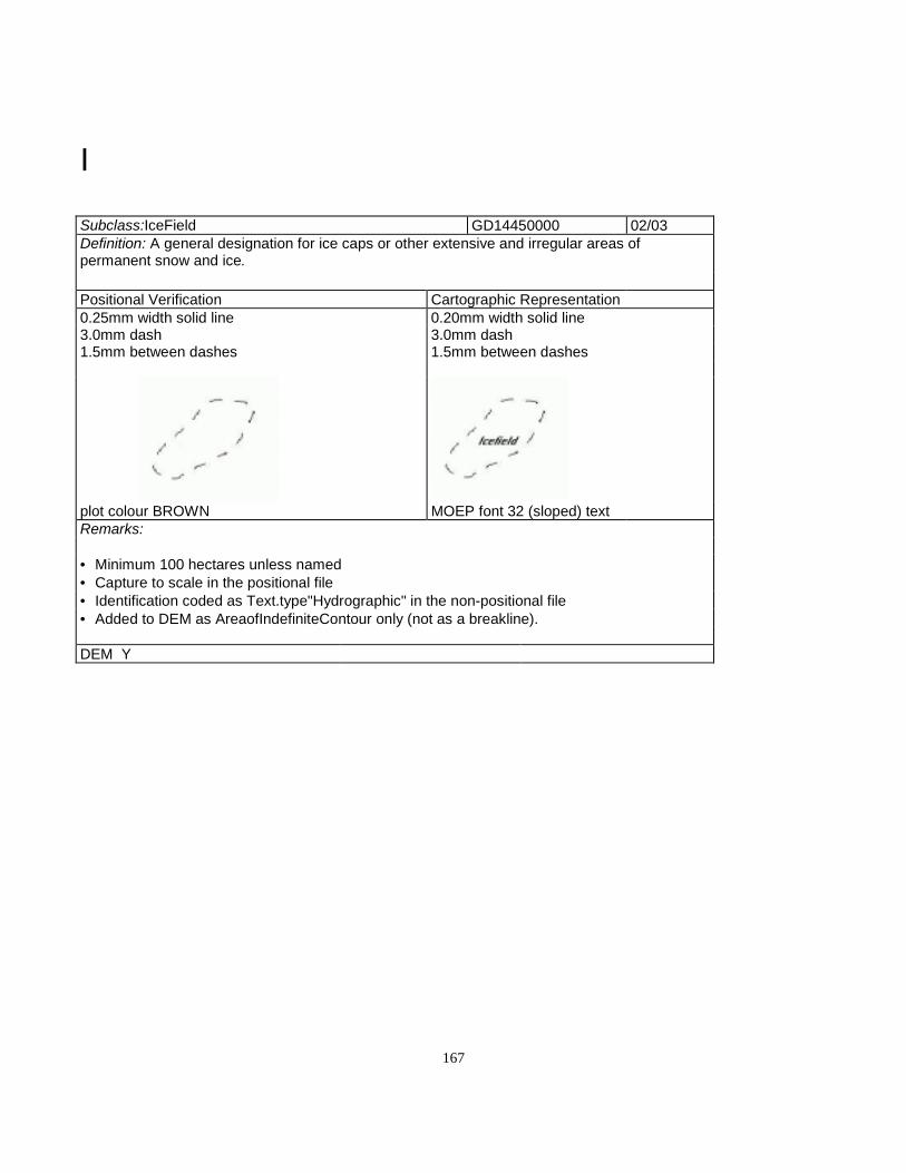
167
I
Subclass:IceField GD14450000 02/03Definition: A general designation for ice caps or other extensive and irregular areas ofpermanent snow and ice.
Positional Verification Cartographic Representation0.25mm width solid line 0.20mm width solid line3.0mm dash 3.0mm dash1.5mm between dashes 1.5mm between dashes
plot colour BROWN MOEP font 32 (sloped) textRemarks:
• Minimum 100 hectares unless named• Capture to scale in the positional file• Identification coded as Text.type"Hydrographic" in the non-positional file• Added to DEM as AreaofIndefiniteContour only (not as a breakline).
DEM Y

168
Subclass:Island (to scale) GE14850000 02/03
(symbolized) GE94850000 01Definition: A land mass completely surrounded by water
Positional Verification Cartographic RepresentationTO SCALE SYMBOLIZED TO SCALE SYMBOLIZED
0.25mm width solid line 0.25mm width solid line 0.25mm width solid line 0.25mm width solidline
2.0mm tick length 2.0mm tick length
+ +
plot colour BLUERemarks:
• To scale - Longest dimension is over 200 metres• This feature feature is not duplicated as a lake boundary• Symbolized - Point feature• No dimension over 200 metres• The cross is aligned with the sheet edge and captured at a 0º angle• All named islands and rocks will be captured• If not visible on the photograph, enter as Island - Position approximate• Captured in the positional file
DEM Y

169
Subclass:IslandGeometric.Representational.Qualifier: Positionapproximate
GE94850100 01
Definition: A land mass completely surrounded by water. Named islands and rocks not visibleon the photograph.
Positional Verification Cartographic Representation0.25mm width solid line 0.25mm width solid line2.0mm cross 2.0mm cross
+POSITION APPROXIMATE
+POSITION APPROXIMATE
plot colour PURPLE MOEP font 31 UPPER CASE textRemarks:
• Approximate position to be established from 1:50 000 NTS published hardcopy andconverted to NAD83,• Captured as a point feature in the positional file• Identification coded as Text.type"Hydrographic" in the non-positional file
DEM N

170
L
Subclass:LakeGeometric.Representational.Qualifier:Definite
GB15300000 02/03
Definition: A body of fresh water that is completely surrounded by land.
Positional Verification Cartographic Representation0.25mm width solid line 0.50mm width solid line
plot colour BLUERemarks:
• Longest dimension is over 25 metres.• The apparent high water mark of the bodt of water is where the presence and action of the water isso common and usual as to mark the soil of the bed of the body of water a character distinct from thatof its banks, in vegetation and in the nature of the soil itself• Captured to scale in the positional file
DEM Y

171
Subclass:LakeGeometric.Representational.Qualifier:Indefinite
GB15300130 02/03
Definition: A body of fresh water that is completely surrounded by land
Positional Verification Cartographic Representation0.25mm width line 0.35mm width line
20.0mm dash1.0mm between dashes
plot colour BLACKRemarks:
• Longest dimension is over 25 metres.• "Indefinite" - Obscured on the aerial photography• The apparent high water mark of the bodt of water is where the presence and action of the water isso common and usual as to mark the soil of the bed of the body of water a character distinct from thatof its banks, in vegetation and in the nature of the soil itself• Captured to scale in the positional file
DEM Y
Subclass:Lake.type"Intermittent" GB15300140 02/03Definition: A fresh waterbody that is normally dry at sometime during the year.
Positional Verification CartographicRepresentation
0.25mm width line 0.25mm width line3.0mm dash 20.0mm dash1.5mm between dashes 1.0mm between dashes
plot colour PURPLERemarks:
• Longest dimension is over 25 metres.• The apparent high water mark of the bodt of water is where the presence and action of the water isso common and usual as to mark the soil of the bed of the body of water a character distinct from thatof its banks, in vegetation and in the nature of the soil itself• Captured to scale in the positional file
DEM Y

172
Subclass:LavaBed HB15850000 02/03Definition: An area where molten rock has flowed from a volcano or fissure and cooled to formsolidified rock.
Positional Verification CartographicRepresentation
0.25mm width line 0.25mm width line3.0mm dash 1.5mm dash0.5mm dot 1.5mm between dashes
plot colour PURPLE MOEP font 31 UPPER CASE textRemarks:
• Longest dimension greater than 200 metres• Captured to scale in the positional file• Identification coded as Text.type"Landform" in the non-positional file
DEM Y

173
Subclass:Library (to scale) BE16200000 02
(symbolized) BE90700000 01Definition: A facility in which literary, musical, artistic, or reference materials as books, manuscripts, recordings, orfilms are kept for use but not for sale.
Positional Verification Cartographic RepresentationTO SCALE SYMBOLIZED TO SCALE SYMBOLIZED
0.25mm width solid line 0.25mm width solid line 0.25mm width solid line 0.25mm widthsolid line
0.8mm open square 0.8mm filledsquare
plot colour BLACK
Remarks:
• Capture to scale in the positional file using the right hand rule when one side is > 30m. or the total area is > 900sq. m.• Capture as a point in the positional file oriented to the true ground position when total area is < 900 sq. m. withno sides > 30m.• Determine building dimensions by the outline of their roofs, including attached garages and multilevel parking.
DEM N
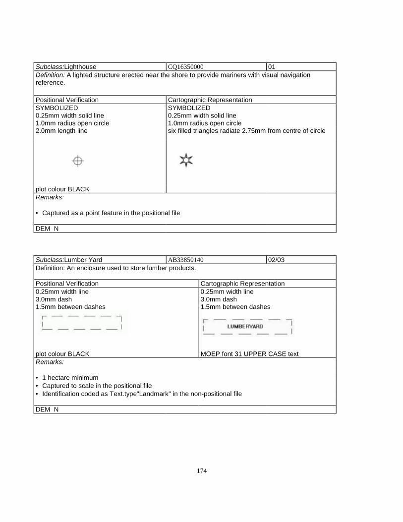
174
Subclass:Lighthouse CQ16350000 01Definition: A lighted structure erected near the shore to provide mariners with visual navigationreference.
Positional Verification Cartographic RepresentationSYMBOLIZED SYMBOLIZED0.25mm width solid line 0.25mm width solid line1.0mm radius open circle 1.0mm radius open circle2.0mm length line six filled triangles radiate 2.75mm from centre of circle
plot colour BLACKRemarks:
• Captured as a point feature in the positional file
DEM N
Subclass:Lumber Yard AB33850140 02/03Definition: An enclosure used to store lumber products.
Positional Verification Cartographic Representation0.25mm width line 0.25mm width line3.0mm dash 3.0mm dash1.5mm between dashes 1.5mm between dashes
plot colour BLACK MOEP font 31 UPPER CASE textRemarks:
• 1 hectare minimum• Captured to scale in the positional file• Identification coded as Text.type"Landmark" in the non-positional file
DEM N

175
MSubclass: MarinaDock CQ08850160 02/03Definition: A marina is a complex for mooring and servicing pleasure boats.
Positional Verification Cartographic Representation0.25mm width solid line 0.25mm width solid line
plot colour BLACK MOEP font 31 UPPER CASE textRemarks:
• Capture main dick as MarinaDock if 50 metres minimum length• Capture as closed polygon if 20 metres in width or greater• May have Piers/Wharfs attached to main dock• Captured to scale in the positional file• Identification coded as Text.type"Landmark"in the non-positional file
DEM N
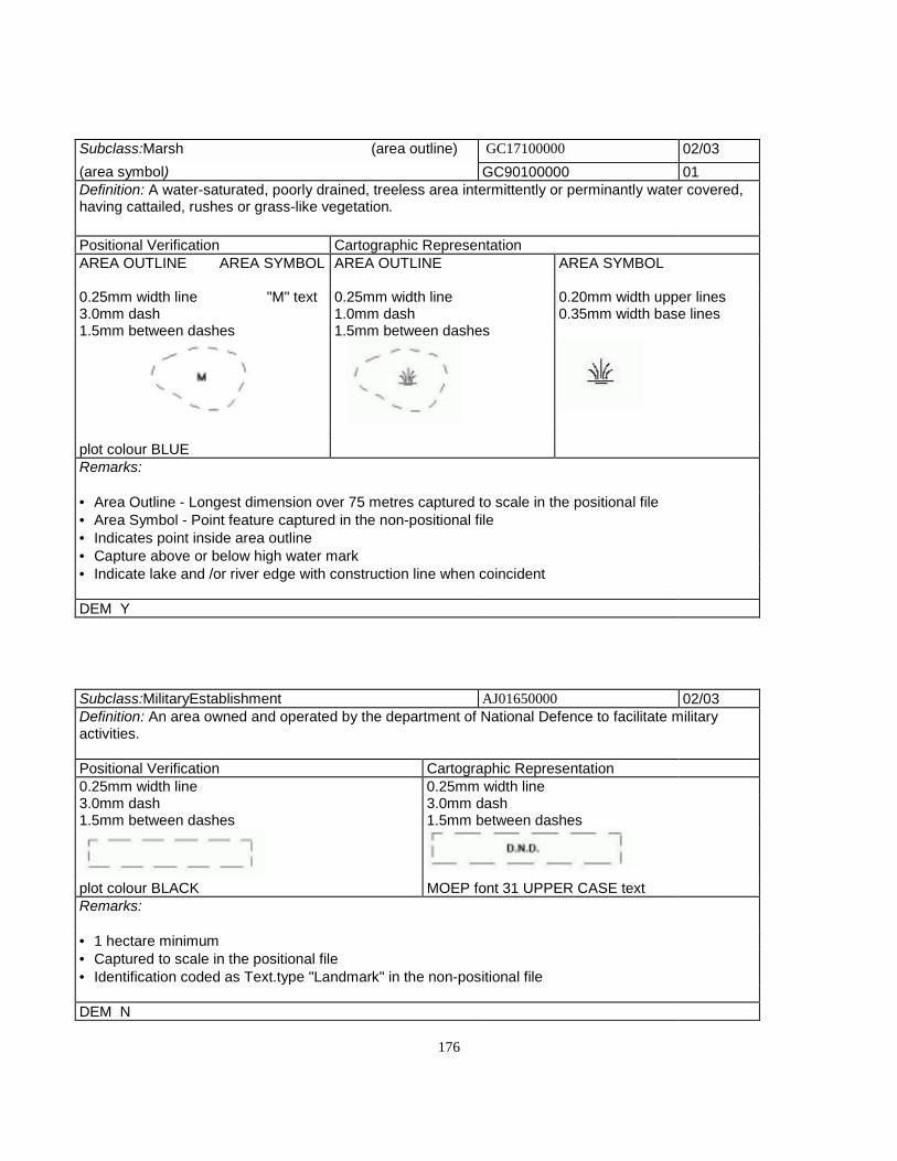
176
Subclass:Marsh (area outline) GC17100000 02/03(area symbol) GC90100000 01Definition: A water-saturated, poorly drained, treeless area intermittently or perminantly water covered,having cattailed, rushes or grass-like vegetation.
Positional Verification Cartographic RepresentationAREA OUTLINE AREA SYMBOL AREA OUTLINE AREA SYMBOL
0.25mm width line "M" text 0.25mm width line 0.20mm width upper lines3.0mm dash 1.0mm dash 0.35mm width base lines1.5mm between dashes 1.5mm between dashes
plot colour BLUERemarks:
• Area Outline - Longest dimension over 75 metres captured to scale in the positional file• Area Symbol - Point feature captured in the non-positional file• Indicates point inside area outline• Capture above or below high water mark• Indicate lake and /or river edge with construction line when coincident
DEM Y
Subclass:MilitaryEstablishment AJ01650000 02/03Definition: An area owned and operated by the department of National Defence to facilitate militaryactivities.
Positional Verification Cartographic Representation0.25mm width line 0.25mm width line3.0mm dash 3.0mm dash1.5mm between dashes 1.5mm between dashes
plot colour BLACK MOEP font 31 UPPER CASE textRemarks:
• 1 hectare minimum• Captured to scale in the positional file• Identification coded as Text.type "Landmark" in the non-positional file
DEM N

177
Subclass:Mine AG17750000 02/03Definition: An excavation, tunnel or area from which mineral substances are extracted.
Positional Verification Cartographic Representation0.25mm width line 0.25mm width line3.0mm dash 3.0mm dash1.5mm between dashes 1.5mm between dashes
plot colour BLACK MOEP font 31 UPPER CASE textRemarks:
• 1 hectare minimum• Captured to scale in the positional file• Identification coded as Text.type "Landmark" in the non-positional file• A dashed box 1 hectare in size will be shown when below minimum size
DEM N
Subclass:Mine.type"OpenPit" AG17600000 02/03Definition: An excavation from which mineral substances are taken. Generally larger than a quarry.
Positional Verification Cartographic Representation0.25mm width line 0.25mm width line3.0mm dash 1.0mm tick length1.5mm between dashes 0.20mm tick width
1.5mm between dashes
plot colour BLACK MOEP font 31 UPPER CASE textRemarks:
• 1 hectare minimum• Captured to scale in the positional file• Identification coded as Text.type "Landmark" in the non-positional file• Feature included in the DEM as AreaofExclusion
DEM Y

178
Subclass:Moraine HB18700000 02/03Definition: A mound, ridge or other accumulation of glacial debris appearing in a variety of topographiclandforms, deposited by direct action of glacial ice.
Positional Verification Cartographic Representation0.25mm width line 0.25mm width line3.0mm dash 1.5mmdash.05mm dot 1.5mm between dashes2.0mm from dash end to dot centre
plot colour PURPLE MOEP font 31 UPPER CASE textRemarks:
• Longest dimension greater than 200 metres• Captured to scale in the positional file• Identification coded as Text.type"Landform" in the non-positional file
DEM Y
Subclass:MountainPeak HB18800000 01Definition: The summit (highest point) of a mountain: especially the summit of a conspicuouslyprecipitous mountain.
Positional Verification Cartographic Representation0.25mm width line 0.25mm width line3.0mm cross 3.0mm cross+ 2353 + 2353
plot colour RED 1.4mm textMOEP font 31 text
Remarks:
• Named mountain peaks only• Captured as a point feature in the positional file• Elevation coded as Text.typ"Hypsographic" in the non-positional file
DEM Y

179
N
Subclass:Nursery JB19150000 02/03Definition: A place where shrubs, flowers, trees etc. are propogated for transplanting or for sesding andgrafting.
Positional Verification Cartographic Representation0.25mm width line 0.20mm width line3.0mm dash 3.0mm dash1.0mm between dashes 1.5mm between dashes
plot colour GREEN MOEP font 31 UPPER CASE textRemarks:
• 1 hectare minimum• Captured to scale in the positional file• Identification coded as Text.type"Landmark" in the non-positional file
DEM N

180
O
Subclass:OilWell CG19600000 01Definition: A shaft or hole sunk into the earth to extract oil.
Positional Verification Cartographic Representation0.25mm width line 0.25mm width line2.0mm open square 2.0mm open square0.5mm radius circle 0.5mm radius circle
plot colour BLACKRemarks:
• Capture as a point feature in the positional file
DEM N

181
Subclass:Orchard JB19650000 02/03Definition: A plantation of fruit or nut bearing trees.
Positional Verification Cartographic Representation0.25mm width solid line 0.25mm width solid line3/0mm dash 3.0mm dash1.5mm between dashes 1.5mm between dashes
plot colour BLACK MOEP font 31 UPPER CASE textRemarks:
• 1 hectare minimum• Captured to scale in the positional file• Identification coded as Text.type"Landmark" in the non-positional file
DEM N
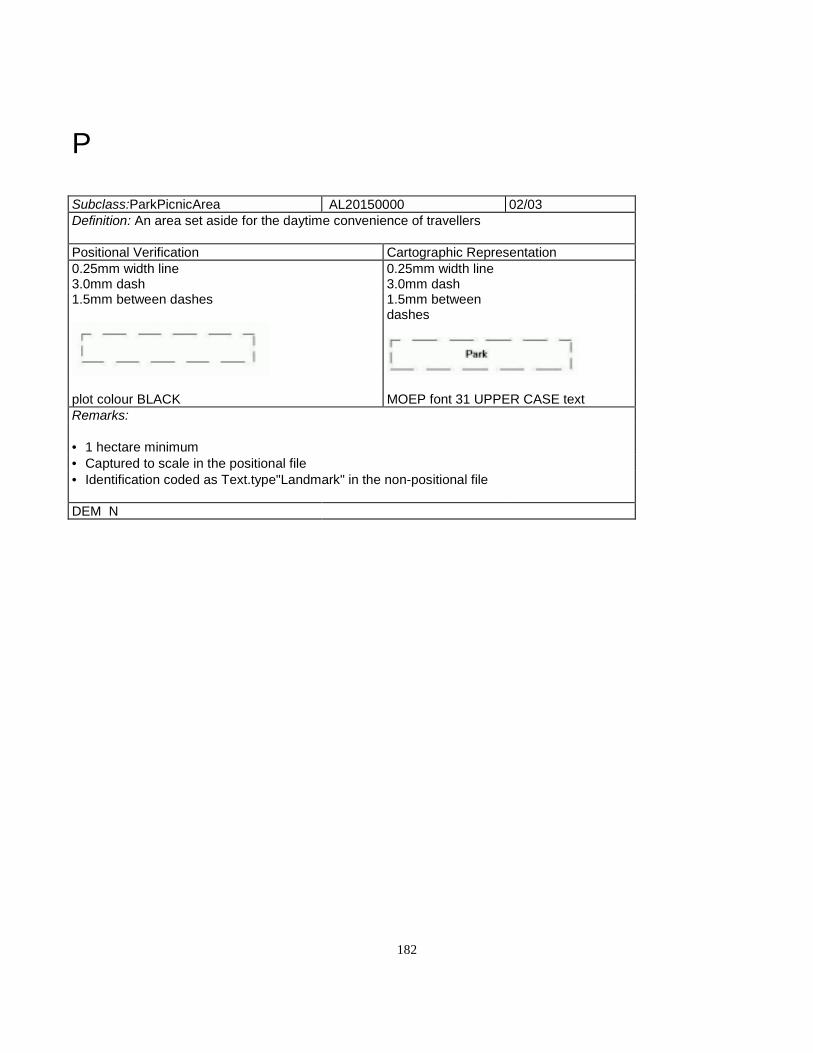
182
P
Subclass:ParkPicnicArea AL20150000 02/03Definition: An area set aside for the daytime convenience of travellers
Positional Verification Cartographic Representation0.25mm width line 0.25mm width line3.0mm dash 3.0mm dash1.5mm between dashes 1.5mm between
dashes
plot colour BLACK MOEP font 31 UPPER CASE textRemarks:
• 1 hectare minimum• Captured to scale in the positional file• Identification coded as Text.type"Landmark" in the non-positional file
DEM N

183
Subclass:Penitentiary (to scale) BF20950000 02
(symbolized) BF90400000 01Definition: A facility in which offenders against the law are confined.
Positional Verification Cartographic Representation0.25mm width solid line 0.25mm width solid line 0.25mm width solid line 0.25mm width solid
line0.8mm open square 0.8mm filled square
plot colour BLACK MOEP font 31 UPPERCASE text
MOEP font 31 UPPERCASE textRemarks:
• Capture to scale in the positional file using the right hand rule when one side is > 30m. or the totalarea is > 900 sq. m.• Capture as a point in the positional file oriented to the true ground position when total area is < 900sq. m. with no sides > 30m.• Determine building dimensions by the outline of their roofs, including attached garages and multilevelparking.• Place building identification as Text.type"Landmark" in the non-positional file, size determined bybuilding size
DEM N
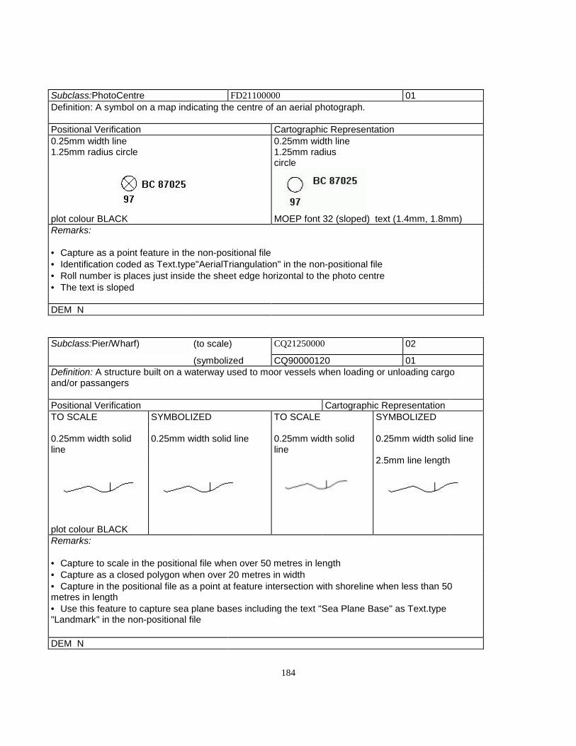
184
Subclass:PhotoCentre FD21100000 01Definition: A symbol on a map indicating the centre of an aerial photograph.
Positional Verification Cartographic Representation0.25mm width line 0.25mm width line1.25mm radius circle 1.25mm radius
circle
plot colour BLACK MOEP font 32 (sloped) text (1.4mm, 1.8mm)Remarks:
• Capture as a point feature in the non-positional file• Identification coded as Text.type"AerialTriangulation" in the non-positional file• Roll number is places just inside the sheet edge horizontal to the photo centre• The text is sloped
DEM N
Subclass:Pier/Wharf) (to scale) CQ21250000 02
(symbolized CQ90000120 01Definition: A structure built on a waterway used to moor vessels when loading or unloading cargoand/or passangers
Positional Verification Cartographic RepresentationTO SCALE SYMBOLIZED TO SCALE SYMBOLIZED
0.25mm width solidline
0.25mm width solid line 0.25mm width solidline
0.25mm width solid line
2.5mm line length
plot colour BLACKRemarks:
• Capture to scale in the positional file when over 50 metres in length• Capture as a closed polygon when over 20 metres in width• Capture in the positional file as a point at feature intersection with shoreline when less than 50metres in length• Use this feature to capture sea plane bases including the text "Sea Plane Base" as Text.type"Landmark" in the non-positional file
DEM N

185
Subclass:Pile AG21275000 02/03Definition: A quantity of things heaped together into a mound.
Positional Verification Cartographic Representation0.25mm width line 0.20mm width line3.0mm dash 3.0mm dash1.5mm between dashes 1.5mm between
dashes
plot colour BLACK MOEP font 31 UPPER CASE textRemarks:
• Minimum area 1 hectare• Captured to scale in the positional file• Identification coded as Text.type"Landmark" in the non-positional file• In the DEM as AreaofExclusion only (not as a man-made breakline)
DEM Y

186
Subclass:Pipeline EA21400000 02Definition: A cylindrical conduit used to convey liquids or gasses
Positional Verification Cartographic Representation0.25mm width line 0.25mm width line1.0mm dash 1.5mm "P" height1.0mm between dashes 30.0mm between
"P"s
plot colour BLACK MOEP font 31 UPPER CASE textRemarks:
• Continuous over 4 kilometres minimum• Symbol "P" is not placed over tower• Captured in the positional file
DEM N

187
Subclass:Pit.type"Abandoned" AG21550001 02/03Definition: An excavation from which sand or gravel has been removed (e.g., borrow pit) No longerused for original purpose.
Positional Verification Cartographic Representation0.25mm width line 0.25mm width line3.0mm dash 3.0mm dash1.5mm between dashes 1.5mm between dashes
1.0mm tick length0.20mm tick width1.5mm betweeen ticks
plot colour BLACK MOEP font 31 UPPER CASE textRemarks:
• 1 hectare minimum• Captured to scale in the positional file• Identification coded as Text.type"Landmark" in the non-positional file• Designated area and associated buildings to be shown as individual features• Included in the DEM as Areaof Exclusion
DEM Y

188
Subclass:Pit.type"GravelSand" AG21550000 02/03Definition: An excavation from which sand or gravel has been removed .
Positional Verification Cartographic Representation0.25mm width line 0.25mm width line3.0mm dash 1.0mm tick length1.5mm between dashes 0.20mm tick width
1.5mm betweeen ticks
plot colour BLACK MOEP font 31 UPPER CASE textRemarks:
• 1 hectare minimum• Captured to scale in the positional file• Identification coded as Text.type"Landmark" in the non-positional file• Designated area and associated buildings to be shown as individual features• Included in the DEM as Areaof Exclusion
DEM Y

189
Subclass:PoliceStation) (to scale BF22000000 02
(symbolized) BF90500000 01Definition: A facility housing the law enforcement agencies for a particular jurisdiction.
Positional Verification Cartographic RepresentationTO SCALE SYMBOLIZED TO SCALE SYMBOLIZED
0.25mm width solid line 0.25mm width solid line 0.25mm width solid line 0.25mm width solidline
0.8mm open square 0.8mm filled square
plot colour BLACK
Remarks:
• Capture to scale in the positional file using the right hand rule when one side is > 30m. or the totalarea is > 900 sq. m.• Capture as a point in the positional file oriented to the true ground position when total area is < 900sq. m. with no sides > 30m.• Determine building dimensions by the outline of their roofs, including attached garages and multilevelparking.
DEM N

190
Subclass:PostOffice (to scale) BF22250000 02
(symbolized) BF90600000 01Definition: A local branch of the national postal system which handles the mail for a particular area.
Positional Verification Cartographic RepresentationTO SCALE SYMBOLIZED TO SCALE SYMBOLIZED
0.25mm width solid line 0.25mm width solid line 0.25mm width solid line 0.25mm width solidline
0.8mm open square 0.8mm filled square
plot colour BLACKRemarks:
• Capture to scale in the positional file using the right hand rule when one side is > 30m. or the totalarea is > 900 sq. m.• Capture as a point in the positional file oriented to the true ground position when total area is < 900sq. m. with no sides > 30m.• Determine building dimensions by the outline of their roofs, including attached garages and multilevelparking.
DEM N

191
Q
Subclass:Quarry GB22500000 02/03Definition: An excavation created by removal of stone by blasting or cutting.
Positional Verification Cartographic Representation0.25mm width solid line 0.35mm width solid line
plot colour BLACK MOEP font 31 UPPER CASE textRemarks:
• 1 hectare minimum• Captured to scale in the positional file• Identification coded as Text.type"Landmark" in the non-positional file• Included in the DEM as Areaof Exclusion
DEM Y
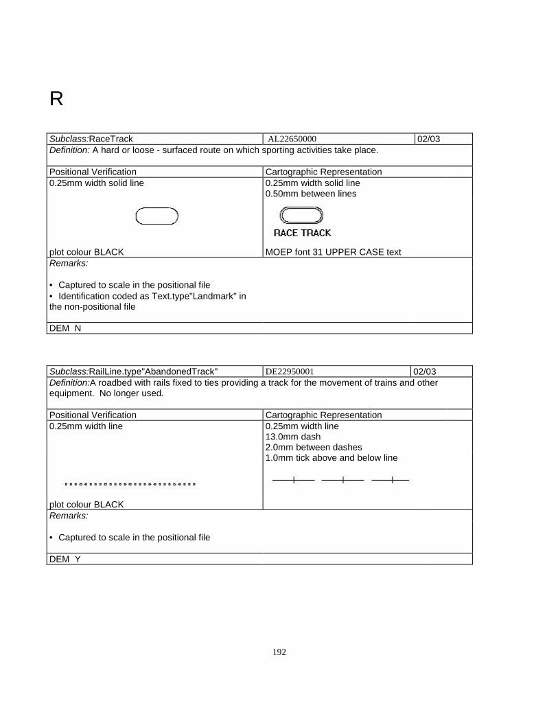
192
R
Subclass:RaceTrack AL22650000 02/03Definition: A hard or loose - surfaced route on which sporting activities take place.
Positional Verification Cartographic Representation0.25mm width solid line 0.25mm width solid line
0.50mm between lines
plot colour BLACK MOEP font 31 UPPER CASE textRemarks:
• Captured to scale in the positional file• Identification coded as Text.type"Landmark" inthe non-positional file
DEM N
Subclass:RailLine.type"AbandonedTrack" DE22950001 02/03Definition:A roadbed with rails fixed to ties providing a track for the movement of trains and otherequipment. No longer used.
Positional Verification Cartographic Representation0.25mm width line 0.25mm width line
13.0mm dash2.0mm between dashes1.0mm tick above and below line
plot colour BLACKRemarks:
• Captured to scale in the positional file
DEM Y
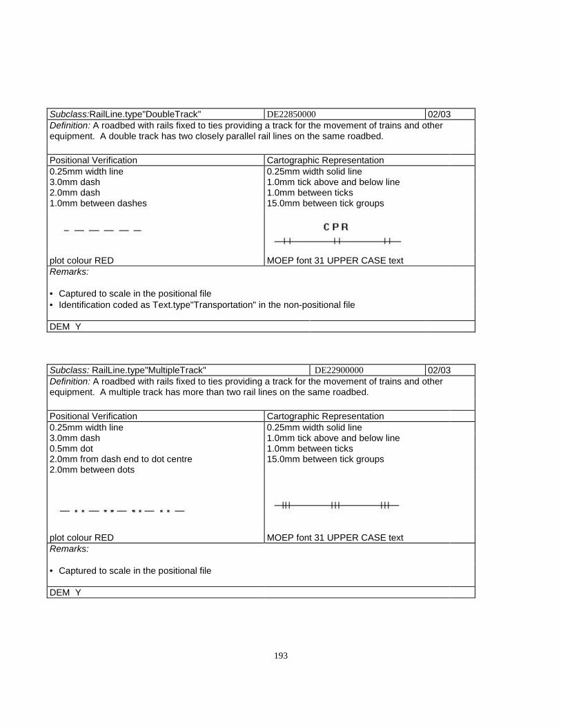
193
Subclass:RailLine.type"DoubleTrack" DE22850000 02/03Definition: A roadbed with rails fixed to ties providing a track for the movement of trains and otherequipment. A double track has two closely parallel rail lines on the same roadbed.
Positional Verification Cartographic Representation0.25mm width line 0.25mm width solid line3.0mm dash 1.0mm tick above and below line2.0mm dash 1.0mm between ticks1.0mm between dashes 15.0mm between tick groups
plot colour RED MOEP font 31 UPPER CASE textRemarks:
• Captured to scale in the positional file• Identification coded as Text.type"Transportation" in the non-positional file
DEM Y
Subclass: RailLine.type"MultipleTrack" DE22900000 02/03Definition: A roadbed with rails fixed to ties providing a track for the movement of trains and otherequipment. A multiple track has more than two rail lines on the same roadbed.
Positional Verification Cartographic Representation0.25mm width line 0.25mm width solid line3.0mm dash 1.0mm tick above and below line0.5mm dot 1.0mm between ticks2.0mm from dash end to dot centre 15.0mm between tick groups2.0mm between dots
plot colour RED MOEP font 31 UPPER CASE textRemarks:
• Captured to scale in the positional file
DEM Y

194
Subclass: RailLine.type"SingleTrack" DE22950000 02/03Definition: A roadbed with rails fixed to ties providing a track for the movement of trains and otherequipment. A single track has one set of rails on the roadbed.
Positional Verification Cartographic Representation0.25mm width line 0.25mm width solid line3.0mm dash 1.0mm tick above and below line0.5mm dot 15.0mm between ticks2.0mm from dash end to dot centre
plot colour RED MOEP font 31 UPPER CASE textRemarks:
• Captured to scale in the positional file• Identification coded as Text.type"Transportation" in the non-positional file
DEM Y
Subclass: RailLine.type"Spur" DE28850000 02/03Definition: A short length of reilway track leading from the main line.
Positional Verification Cartographic Representation0.25mm width solid line .25mm width solid line3.0mm dash 1.0mm tick above and below line0.5mm dot 15.0mm between ticks2.0mm from dash end to dot centre 1.5mm between lines
plot colour REDRemarks:
• Captured to scale in the positional file
DEM Y

195
Subclass: Rapids (to scale) GA23500000 02(symbolized) GA23500110 01Definition: A fast flowing section of a watercourse or waterbody, generally with exposed rocks andboulders.
Positional Verification Cartographic RepresentationTO SCALE SYMBOLIZED TO SCALE SYMBOLIZED
0.25mm width line 0.5mm dots 0.25mm width line 0.25mm width line
Line extends 1.0mm 3.5mm linebeyond stream banks perpindicular to stream
plot colour BLUE MOEP font 32 (sloped) textRemarks:
• To sacle - Captured on double line rivers only• Straight lines are perpindicular to river banks• Symbolized - Point feature Captured on single line rivers only• Point placed at the beginning and end of rapids• Captured in the positional file• Identification coded as Text.type"Hydrographic" in the non-positional file• Note: Associated text is sloped e.g. "Rapids"
DEM N

196
Subclass: ReservoirGeometric Representation Qualifier: Definite
GB24300000 02/03
Definition: An artificial basin where water iscollected and kept.
Positional Verification Cartographic Representation0.25mm width solid line 0.35mm width solid line
plot colour RED MOEP font 32 (sloped) textRemarks:
• Longest dimension over 25 metres• Captured in the positional file• Identification coded as Text.type"Hydrographic" in the non-positional file• NOTE - text is sloped. e.g., "Reservoir"
DEM Y
Subclass: Reservoir Geometric Representation Qualifier: Indefinite
GB90100000 02/03
Definition: An artificial basin where water is collected and kept.
Positional Verification Cartographic Representation0.25mm width solid line 0.35mm width solid line3.0mm dash 20.0mm dash1.5mm between dashes 1.0mm between dashes
plot colour RED MOEP font 32 (sloped) textRemarks:
• Longest dimension over 25 metres• The apparent high water mark of the body of water is where the presence and action of the water areso common and usual as to mark the soil of the bed of the body of water a character distinct from that ofist banks, in vegetation and in the nature of the soil itself.• Captured to scale in the positional file• Identification coded as Text.type"Hydrographic" in the non-positional file
DEM Y
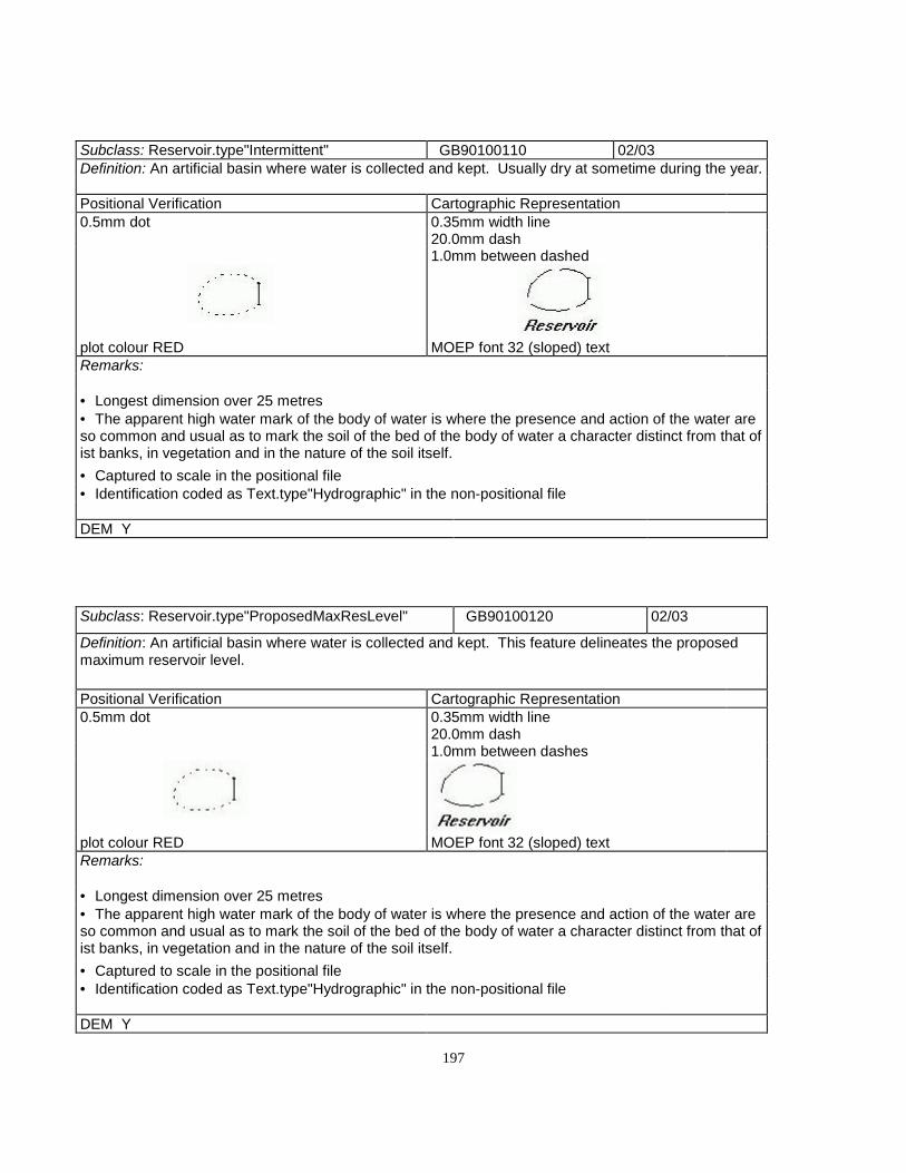
197
Subclass: Reservoir.type"Intermittent" GB90100110 02/03Definition: An artificial basin where water is collected and kept. Usually dry at sometime during the year.
Positional Verification Cartographic Representation0.5mm dot 0.35mm width line
20.0mm dash1.0mm between dashed
plot colour RED MOEP font 32 (sloped) textRemarks:
• Longest dimension over 25 metres• The apparent high water mark of the body of water is where the presence and action of the water areso common and usual as to mark the soil of the bed of the body of water a character distinct from that ofist banks, in vegetation and in the nature of the soil itself.• Captured to scale in the positional file• Identification coded as Text.type"Hydrographic" in the non-positional file
DEM Y
Subclass: Reservoir.type"ProposedMaxResLevel" GB90100120 02/03
Definition: An artificial basin where water is collected and kept. This feature delineates the proposedmaximum reservoir level.
Positional Verification Cartographic Representation0.5mm dot 0.35mm width line
20.0mm dash1.0mm between dashes
plot colour RED MOEP font 32 (sloped) textRemarks:
• Longest dimension over 25 metres• The apparent high water mark of the body of water is where the presence and action of the water areso common and usual as to mark the soil of the bed of the body of water a character distinct from that ofist banks, in vegetation and in the nature of the soil itself.• Captured to scale in the positional file• Identification coded as Text.type"Hydrographic" in the non-positional file
DEM Y

198
Subclass: RifleRange AL23300140 02/03Definition: A facility designed for target shootingwith rifles.
Positional Verification Cartographic Representation0.25mm width line 0.25mm width line3.0mm dash 3.0mm dash1.5mm between dashes 1.5mm between dashes
plot colour BLACK MOEP font 31 UPPER CASE textRemarks:
• 1 hectare minimum• Captured to scale in the positional file• Identification coded as Text.type"Landmark" in the non-positional file
DEM N

199
Subclass: River/Stream GeometricRepresentation Qualifier: Definite
GA24850000 02/03
Definition: The course followed by the natural flow of water on the earth's surface, draining in an area orbody of water.
Positional Verification Cartographic Representation0.25mm width solid line 0.35mm width solid line
plot colour BLUERemarks:
• Captured in the positional file• Line is captured at the centerline of the feature• "Definite" - Not obscured on the aerial photograph• Maximum width 20 metres• If over 20 metres in width capture as River/Stream.type"LeftBank" or River/stream.type"RightBank"• River/Streams shall be shown as continuous, even flowing through lake features that are below theminimum size specifications, or throurh swamp or marsh areas• Hanging drainage will be avoided when possible• Definite or intermittent drainages may have portions classified as definite in limited situations whenthe water course is obscured• A definite stream cannot flow into an intermittent stream• If an oxbow has water in it and not joined to a double sided river then capture as a lake• If an oxbow has water in it and is joined to a double sided river at one end, capture as pert of the river• If the oxbow is dry capture as dry river bed• Definite and internittent drainages may have portions classified as indefinite in limited situationswhere the water course is obscured by vegetation, shadow, etc.• A definite stream cannot flow into an intermittent stream
DEM Y

200
Subclass: River/Stream GeometricRepresentation Qualifier: Indefinite
GA24850140 02/03
Definition: The course followed by the natural flow of water on the earth's surface, draining in an area orbody of water.
Positional Verification Cartographic Representation0.25mm width solid line 0.35mm width line
20.0mm dash1.0mm between dashes
plot colour BLACK MOEP font 31 UPPER CASE textRemarks:
• Captured in the positional file• Line is captured at the centerline of the feature• "Indefinite" - Obscured on the aerial photograph• Maximum width 20 metres• if over 20 metres in width capture as River/Stream.type"LeftBank" or River/stream.type"RightBank"• River/Streams shall be shown as continuous, even flowing through lake features that are below theminimum size specifications, or throurh swamp or marsh areas• Hanging drainage will be avoided when possible• Definite or intermittent drainages may have portions classified as definite in limited situations whenthe water course is obscured• A definite stream cannot flow into an intermittent stream• Definite and internittent drainages may have portions classified as indefinite in limited situationswhere the water course is obscured by vegetation, shadow, etc.• A definite stream cannot flow into an intermittent stream
DEM Y
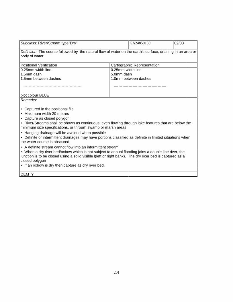
201
Subclass: River/Stream.type"Dry" GA24850130 02/03
Definition: The course followed by the natural flow of water on the earth's surface, draining in an area orbody of water.
Positional Verification Cartographic Representation0.25mm width line 0.25mm width line1.5mm dash 5.0mm dash1.5mm between dashes 1.0mm between dashes
plot colour BLUERemarks:
• Captured in the positional file• Maximum width 20 metres• Capture as closed polygon• River/Streams shall be shown as continuous, even flowing through lake features that are below theminimum size specifications, or throurh swamp or marsh areas• Hanging drainage will be avoided when possible• Definite or intermittent drainages may have portions classified as definite in limited situations whenthe water course is obscured• A definite stream cannot flow into an intermittent stream• When a dry river bed/oxbow which is not subject to annual flooding joins a double line river, thejunction is to be closed using a solid visible l(left or right bank). The dry ricer bed is captured as aclosed polygon• If an oxbow is dry then capture as dry river bed.
DEM Y

202
Subclass: River/Stream.type"LeftBank" GA90000110 02/03
Definition: The course followed by the natural flow of water on the earth's surface, draining in an area orbody of water. A definite watercourse of sufficient width to delineate separate banks. "Left-Bank"indicates the left shoreline heading downstream
Positional Verification Cartographic Representation0.25mm width solid line 0.35mm width solid line
plot colour BLUERemarks:
• Captured in the positional file• Maximum width 20 metres• River/Streams shall be shown as continuous, even flowing through lake features that are below theminimum size specifications, or throurh swamp or marsh areas• Hanging drainage will be avoided when possible• Definite or intermittent drainages may have portions classified as definite in limited situations whenthe water course is obscured• The apparent high water mark of the body of water is where the presence and action of the water areso common and usual as to mark the soil of the bed of the body of water a character distinct from that ofits banks, in vegetation and in the nature of the soil itself.• When a dry river bed/oxbow which is not subject to annual flooding joins a double line river, thejunction is to be closed using a solid visible l(left or right bank).• If an oxbow has water in it and is joined to a double sided river at one end, capture as pert of the river
DEM Y

203
Subclass: River/Stream.type"Intermittent" GA24850150 02/03Definition: The course followed by the natural flow of water on the earth's surface, draining in an area orbody of water. A definite watercourse that is usually dry, depending upon the season and precipitation.
Positional Verification Cartographic Representation0.25mm width line 0.25mm width line3.0mm dash 1.5mm dash1.5mm between dashes 2.0mm short dash
1.0mm between dashes
plot colour BLUERemarks:
• Captured in the positional file• Line is captured at the centerline of the feature• Maximum width 20 metres• If over 20 metres in width capture as River/Stream.type"LeftBank" or River/stream.type"RightBank"• River/Streams shall be shown as continuous, even flowing through lake features that are below theminimum size specifications, or throurh swamp or marsh areas• Hanging drainage will be avoided when possible• Definite or intermittent drainages may have portions classified as definite in limited situations whenthe water course is obscured• A definite stream cannot flow into an intermittent stream• Definite and internittent drainages may have portions classified as indefinite in limited situationswhere the water course is obscured by vegetation, shadow, etc.• A definite stream cannot flow into an intermittent stream
DEM Y

204
Subclass: River/Stream.type"RightBank" GA90000120 02/03Definition: The course followed by the natural flow of water on the earth's surface, draining in an area orbody of water. A definite watercourse of sufficient width to delineate separate banks. "Right-Bank"indicates the right shoreline heading downstream
Positional Verification Cartographic Representation0.25mm width solid line 0.35mm width solid line
plot colour BLUERemarks:
• Captured in the positional file• Maximum width 20 metres• River/Streams shall be shown as continuous, even flowing through lake features that are below theminimum size specifications, or throurh swamp or marsh areas• Hanging drainage will be avoided when possible• Definite or intermittent drainages may have portions classified as definite in limited situations whenthe water course is obscured• The apparent high water mark of the body of water is where the presence and action of the water areso common and usual as to mark the soil of the bed of the body of water a character distinct from that ofits banks, in vegetation and in the nature of the soil itself.• When a dry river bed/oxbow which is not subject to annual flooding joins a double line river, thejunction is to be closed using a solid visible l(left or right bank).• If an oxbow has water in it and is joined to a double sided river at one end, capture as pert of the river
DEM Y

205
Subclass: Road.surface"Loose".lanes"1".type"Undivided" DA25000110 02/03Definition: A specially prepared route on land for the movement of vehicles (other than railway vehicles)from place to place. A 1 lane road with surface of aggrigate, soil or clay.
Positional Verification Cartographic Representation0.25mm width line 0.20mm width line3.0mm dash 5.0mm dash1.5mm between dashes 1.0mm between dashes
0.5mm between lines
plot colour ORANGE MOEP font 31 UPPER CASE textRemarks:
• Cart track, Access road, gravel driveway over 400 metres• Captured in the positional file
DEM Y
Subclass:Road.surface"Loose".lanes"1".type"Undivided".status"U/C"
DA25000160 02/03
Definition: A specially prepared route on land for the movement of vehicles (other than railway vehicles)from place to place. A 1 lane road with surface of aggrigate, soil or clay that is under construction attime of data capture.
Positional Verification Cartographic Representation0.25mm width line 0.20mm width line3.0mm dash 5.0mm dash2.0mm dash 1.0mm between dashes1.0mm between dashes 0.5mm between lines
plot colour ORANGE MOEP font 31 UPPER CASE textRemarks:
• Captured in the positional file
DEM Y
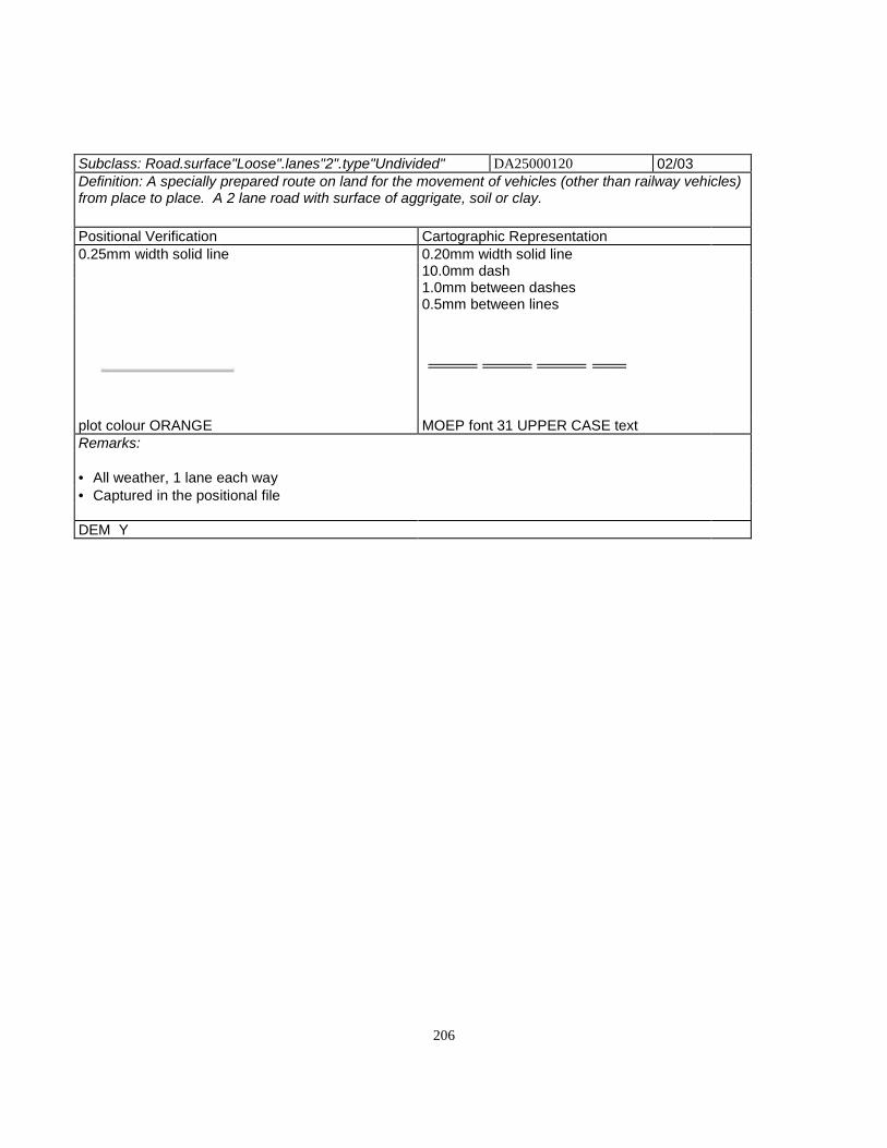
206
Subclass: Road.surface"Loose".lanes"2".type"Undivided" DA25000120 02/03Definition: A specially prepared route on land for the movement of vehicles (other than railway vehicles)from place to place. A 2 lane road with surface of aggrigate, soil or clay.
Positional Verification Cartographic Representation0.25mm width solid line 0.20mm width solid line
10.0mm dash1.0mm between dashes0.5mm between lines
plot colour ORANGE MOEP font 31 UPPER CASE textRemarks:
• All weather, 1 lane each way• Captured in the positional file
DEM Y
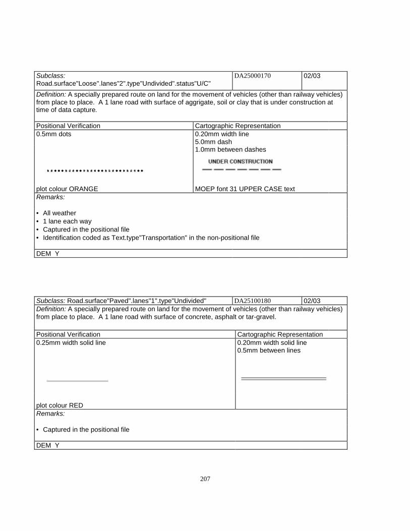
207
Subclass:Road.surface"Loose".lanes"2".type"Undivided".status"U/C"
DA25000170 02/03
Definition: A specially prepared route on land for the movement of vehicles (other than railway vehicles)from place to place. A 1 lane road with surface of aggrigate, soil or clay that is under construction attime of data capture.
Positional Verification Cartographic Representation0.5mm dots 0.20mm width line
5.0mm dash1.0mm between dashes
plot colour ORANGE MOEP font 31 UPPER CASE textRemarks:
• All weather• 1 lane each way• Captured in the positional file• Identification coded as Text.type"Transportation" in the non-positional file
DEM Y
Subclass: Road.surface"Paved".lanes"1".type"Undivided" DA25100180 02/03Definition: A specially prepared route on land for the movement of vehicles (other than railway vehicles)from place to place. A 1 lane road with surface of concrete, asphalt or tar-gravel.
Positional Verification Cartographic Representation0.25mm width solid line 0.20mm width solid line
0.5mm between lines
plot colour REDRemarks:
• Captured in the positional file
DEM Y
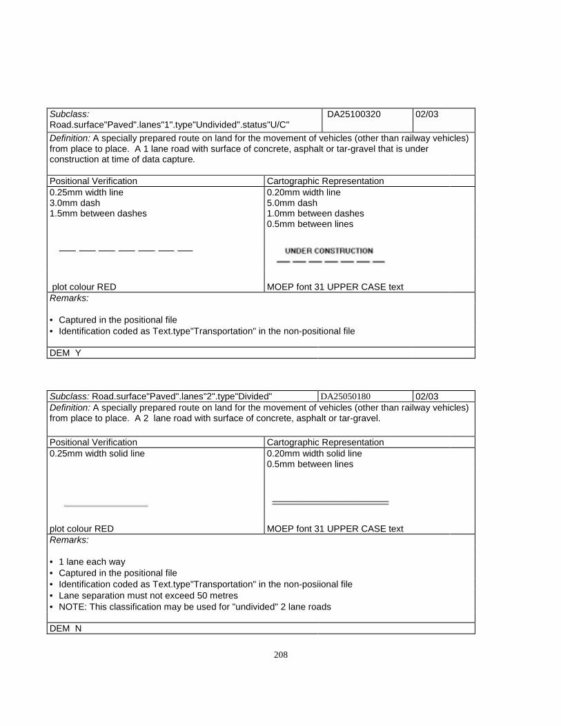
208
Subclass:Road.surface"Paved".lanes"1".type"Undivided".status"U/C"
DA25100320 02/03
Definition: A specially prepared route on land for the movement of vehicles (other than railway vehicles)from place to place. A 1 lane road with surface of concrete, asphalt or tar-gravel that is underconstruction at time of data capture.
Positional Verification Cartographic Representation0.25mm width line 0.20mm width line3.0mm dash 5.0mm dash1.5mm between dashes 1.0mm between dashes
0.5mm between lines
plot colour RED MOEP font 31 UPPER CASE textRemarks:
• Captured in the positional file• Identification coded as Text.type"Transportation" in the non-positional file
DEM Y
Subclass: Road.surface"Paved".lanes"2".type"Divided" DA25050180 02/03Definition: A specially prepared route on land for the movement of vehicles (other than railway vehicles)from place to place. A 2 lane road with surface of concrete, asphalt or tar-gravel.
Positional Verification Cartographic Representation0.25mm width solid line 0.20mm width solid line
0.5mm between lines
plot colour RED MOEP font 31 UPPER CASE textRemarks:
• 1 lane each way• Captured in the positional file• Identification coded as Text.type"Transportation" in the non-posiional file• Lane separation must not exceed 50 metres• NOTE: This classification may be used for "undivided" 2 lane roads
DEM N

209
Subclass:Road.surface"Paved".lanes"2".type"Divided".status"U/C"
DA25050310 02/03
Definition: A specially prepared route on land for the movement of vehicles (other than railway vehicles)from place to place. A 2 lane road with surface of concrete, asphalt or tat-gravel that is underconstruction at time of capture.
Positional Verification Cartographic Representation0.25mm width line 0.20mm width line3.0mm dash 5.0mm dash1.5mm between dashes 1.0mm between dashes
0.5mm between lines
plot colour RED MOEP font 31 UPPER CASE textRemarks:
• 1 lane each way• Captured in the positional file• Identification coded as Text.type"Transportation" in the non-positional file• Lane separation must m=not exceed 50 metres• NOTE: This classification may be used for "undivided" 2 lane roads
DEM Y

210
Subclass: Road.surface"Paved".lanes"2".lanedir"OneWay" DA25100190 02/03Definition: A specially prepared route on land for the movement of vehicles (other than railway vehicles)from place to place. A 2 lane road with surface of concrete, asphalt or tar-gravel.
Positional Verification CartographicRepresentation
0.25mm width line 0.20mm width solidline
3.0mm dash 0.5mm between lines.05mm dot
2.0mm from dash end to dot centre2.0mm between dotsplot colour BROWNRemarks:
• 2 lanes one way• Captured in the positional file
DEM Y
Subclass:Road.surface"Paved".lanes"2".lanedir"OneWay".status"U/C"
DA25100330 02/03
Definition: A specially prepared route on land for the movement of vehicles (other than railway vehicles)from place to place. A 2 lane unidirectional road with a surface of concrete, asphalt or tar-gravel thatis under construction at time of data capture.
Positional Verification Cartographic Representation0.5mm dot 0.20mm width line
5.0mm dash1.0mm between dashes
0.5mm between lines
plot colour BROWN MOEP font 31 UPPER CASE textRemarks:
• 2 lane one way• Captured in the positional file• Identification coded as Text.type"Transportation" in the non-positional file
DEM Y

211
Subclass: Road.surface"Paved".lanes"3".type"Undivided" DA25100200 02/03
Definition: A specially prepared route on land for the movement of vehicles (other than railway vehicles)from place to place. A 3 lane road with surface of concrete, asphalt or tat-gravel.
Positional Verification Cartographic Representation0.25mm width line 0.25mm width solid line3.0mm dash 1.0mm between lines1.5mm between dashes
plot colour PURPLERemarks:
• Typically 3 lanes one way• Captured in the positional file
DEM Y
Subclass:Road.surface"Paved".lanes"3".type"Undivided".status"U/C"
DA25100340 02/03
Definition: A specially prepared route on land for the movement of vehicles (other than railway vehicles)from place to place. A 3 lane road with a surface of concrete, asphalt or tar-gravel that is underconstruction at time of capture.
Positional Verification Cartographic Representation0.25mm width line 0.25mm width line3.0mm dash 5.0mm dash2.0mm dash 1.0mm between dashes
1.0mm between dashes 1.0mm between lines
plot colour PURPLE MOEP font 31 UPPER CASE textRemarks:
• Typically 3 lanes one way• Captured in the positional file• Identification coded as Text.type"Transportation" in the non-positional file
DEM Y
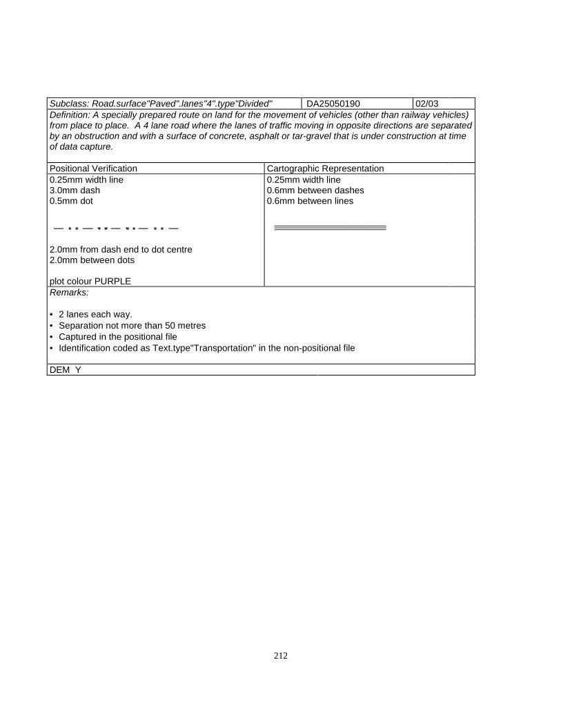
212
Subclass: Road.surface"Paved".lanes"4".type"Divided" DA25050190 02/03Definition: A specially prepared route on land for the movement of vehicles (other than railway vehicles)from place to place. A 4 lane road where the lanes of traffic moving in opposite directions are separatedby an obstruction and with a surface of concrete, asphalt or tar-gravel that is under construction at timeof data capture.
Positional Verification Cartographic Representation0.25mm width line 0.25mm width line3.0mm dash 0.6mm between dashes0.5mm dot 0.6mm between lines
2.0mm from dash end to dot centre2.0mm between dots
plot colour PURPLERemarks:
• 2 lanes each way.• Separation not more than 50 metres• Captured in the positional file• Identification coded as Text.type"Transportation" in the non-positional file
DEM Y

213
Subclass:Road.surface"Paved".lanes"4".type"Divided".statue"U/C"
DA25050320 02/03
Definition: A specially prepared route on land for the movement of vehicles (other than railway vehicles)from place to place. A 4 lane road where the lanes of traffic moving in opposite directions are separatedby an obstruction and with a surface of concrete, asphalt or tar-gravel that is under construction at timeof data capture.
Positional Verification Cartographic Representation0.25mm width line 0.25mm width line3.0mm dash 5.0mm dash2.0mm dot 1.0mm between dashes
1.0mm between dashes 0.6mm between lines
plot colour PURPLE MOEP font 31 UPPER CASE textRemarks:
• 2 lanes each way.• Separation not more than 50 metres• Captured in the positional file• Identification coded as Text.type"Transportation" in the non-positional file
DEM Y
Subclass:Road.surface"Paved".lanes"4".type"Undivided" DA25100210 02/03Definition: A specially prepared route on land for the movement of vehicles (other than railway vehicles)from place to place. A 4 lane road where the lanes of traffic moving in opposite directions are notseparated by an obstruction with a surface of concrete, asphalt or tar-gravel.
Positional Verification Cartographic Representation0.25mm width line 0.25mm width solid line1.5mm dash 1.0mm between lines1.5mm between dashes
plot colour PURPLERemarks:
• 2 lanes each way• Not divided• Captured in the positional file
DEM Y

214
Subclass:Road.surface"Paved".lanes"4".type"Divided".status"U/C"
DA25100350 02/03
Definition: A specially prepared route on land for the movement of vehicles (other than railway vehicles)from place to place. A 4 lane road where the lanes of traffic moving in opposite directions are notseparated by an obstruction with a surface of concrete, asphalt or tar-gravel that is under construction attime of capture.
Positional Verification Cartographic Representation0.5mm dot 0.25mm width line
5.0mm dash1.0mm between dashes
1.0mm between lines
plot colour PURPLE MOEP font 31 UPPER CASE textRemarks:
2 lanes each wayNot dividedCaptured in the positional fileIdentification coded as Text.type"Transportation" in the non-positional file
DEM Y
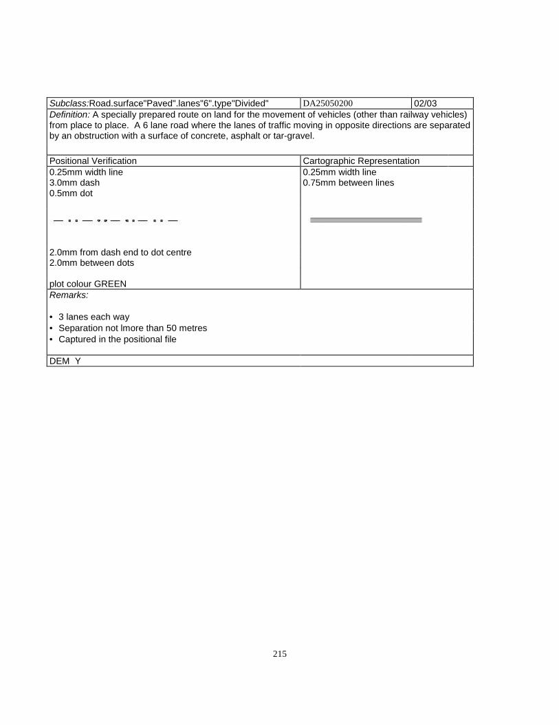
215
Subclass:Road.surface"Paved".lanes"6".type"Divided" DA25050200 02/03Definition: A specially prepared route on land for the movement of vehicles (other than railway vehicles)from place to place. A 6 lane road where the lanes of traffic moving in opposite directions are separatedby an obstruction with a surface of concrete, asphalt or tar-gravel.
Positional Verification Cartographic Representation0.25mm width line 0.25mm width line3.0mm dash 0.75mm between lines0.5mm dot
2.0mm from dash end to dot centre2.0mm between dots
plot colour GREENRemarks:
• 3 lanes each way• Separation not lmore than 50 metres• Captured in the positional file
DEM Y

216
Subclass:Road.surface"Paved".lanes"6".type"Divided".status"U/C"
DA25050330 02/03
Definition: A specially prepared route on land for the movement of vehicles (other than railway vehicles)from place to place. A 6 lane road where the lanes of traffic moving in opposite directions are separatedby an obstruction with a surface of concrete, asphalt or tar-gravel that is under construction at time ofcapture
Positional Verification Cartographic Representation0.25mm width line 0.25mm width line3.0mm dash 5.0mm dash2.0mm dash 1.0mm between dashes
0.75mm between lines
1.0mm between dashes
plot colour GREEN MOEP font 31 UPPER CASE textRemarks:
• 3 lanes each way• Separation not lmore than 50 metres• Captured in the positional file• Identification coded as Text.type "Transportation" in the non-positional file
DEM Y
Subclass:Road.surface"Paved".lanes"6".type"Undivided" DA25100220 02/03
Definition: A specially prepared route on land for the movement of vehicles (other than railway vehicles)from place to place. A 6 lane road where the lanes of traffic moving in opposite directions are notseparated by an obstruction with a surface of concrete, asphalt or tar-gravel.
Positional Verification Cartographic Representation0.25mm width line 0.25mm width solid line1.5mm dash 1.25mm between lines1.5mm between dashes
plot colour GREENRemarks:
• 3 lanes each way• Not divided• Captured in the positional file
DEM Y

217
Subclass:Road.surface"Paved".lanes"6".type"Divided".status"U/C"
DA25100360 02/03
Definition: A specially prepared route on land for the movement of vehicles (other than railway vehicles)from place to place. A 6 lane road where the lanes of traffic moving in opposite directions are notseparated by an obstruction with a surface of concrete, asphalt or tar-gravel that is under construction attime of capture.
Positional Verification Cartographic Representation0.5mm dot 0.25mm width line
5.0mm dash1.0mm between dashes
1.25mm between lines
plot colour GREEN MOEP font 31 UPPER CASE textRemarks:
• 3 lanes each way• Not divided• Captured in the positional file• Identification coded as Text.type"Transportation" in the non-positional file
DEM Y

218
Subclass:Road.surface"Rough" DA25150000 02/03Definition: A specially prepared route on land for the movement of vehicles (other than railway vehicles)from place to place. An unimproved route (logging or secondary road) (4-wheel drive only)
Positional Verification Cartographic Representation0.25mm width line 0.25mm width line1.5mm dash 5.0mm dash1.5mm between dashes 1.0mm between dashes
plot colour ORANGERemarks:
• Logging road (secondary)• 4-wheel drive only• 400 metres minimum• Captured in the positional file
DEM Y
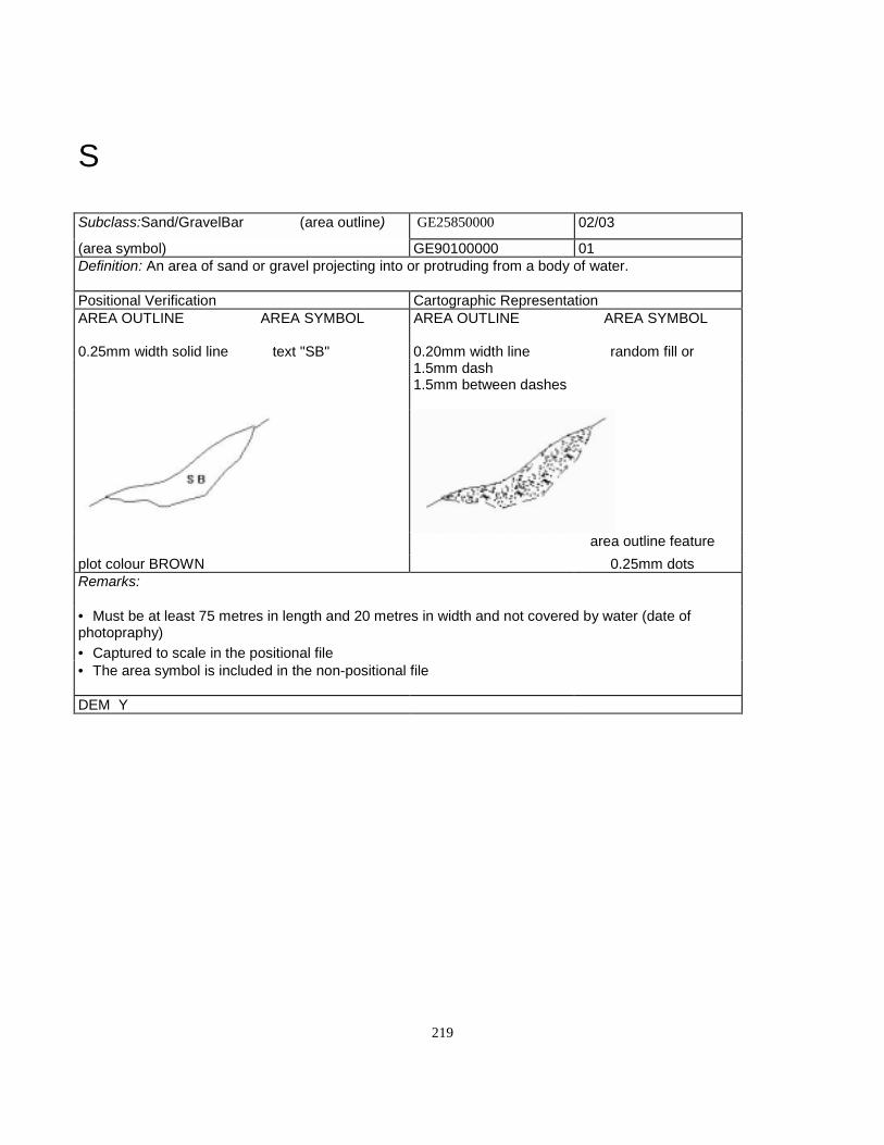
219
S
Subclass:Sand/GravelBar (area outline) GE25850000 02/03
(area symbol) GE90100000 01Definition: An area of sand or gravel projecting into or protruding from a body of water.
Positional Verification Cartographic RepresentationAREA OUTLINE AREA SYMBOL AREA OUTLINE AREA SYMBOL
0.25mm width solid line text "SB" 0.20mm width line random fill or1.5mm dash1.5mm between dashes
area outline featureplot colour BROWN 0.25mm dotsRemarks:
• Must be at least 75 metres in length and 20 metres in width and not covered by water (date ofphotopraphy)• Captured to scale in the positional file• The area symbol is included in the non-positional file
DEM Y

220
Subclass:School (to scale) BE26000000 02
(symbolized) BE90900000 01Definition: An institution for primaty or secondary education.
Positional Verification Cartographic RepresentationTO SCALE SYMBOLIZED TO SCALE SYMBOLIZED
0.25mm width solid line 0.25mm width solid line 0.25mm width solid line 0.25mm widthsolid line
0.8mm open square 0.8mm filledsquare
MOEP font 31 UPPERCASE text
plot colour BLACK MOEP font 31 UPPER CASEtext
Remarks:
• Capture to scale in the positional file using the right hand rule when one side is > 30m. or the totalarea is > 900 sq. m.• Capture as a point in the positional file oriented to the true ground position when total area is < 900sq. m. with no sides > 30m.• Determine building dimensions by the outline of their roofs, including attached garages and multilevelparking.• Place building identification as Text.type"Landmark" in the non-positional file, size determined bybuilding size
DEM N

221
Subclass:Scree HB26150000 02/03Definition: A sloping mass of debris consisting of stones and rock fragments located at the foot of acliff or steep rocky face.
Positional Verification Cartographic Representation0.25mm width line 0.25mm width line3.0mm dash 1.5mm dash0.5mm between dashes 1.5mm between dashes
2.0mm from dash end to dot centre MOEP font 31 UPPER CASE text
plot colour PURPLERemarks:
• Longest dimension 600 metres• Captured to scaler in the positional file• Identification coded as Text.type"Landform" in the non-positional file
DEM N
Subclass:SeaWall GE26250000 02/03Definition: A wall built to prevent toe encroachment of sea water on land.
Positional Verification CartographicRepresentation
0.25mm width solid line 0.25mm width solid line1.25mm filled triangle4.0mm between triangles
plot colour BLACKRemarks:
Minimum length 100 metresLine-low sideTriangles - high side (right side)Captured in the positional file
DEM Y
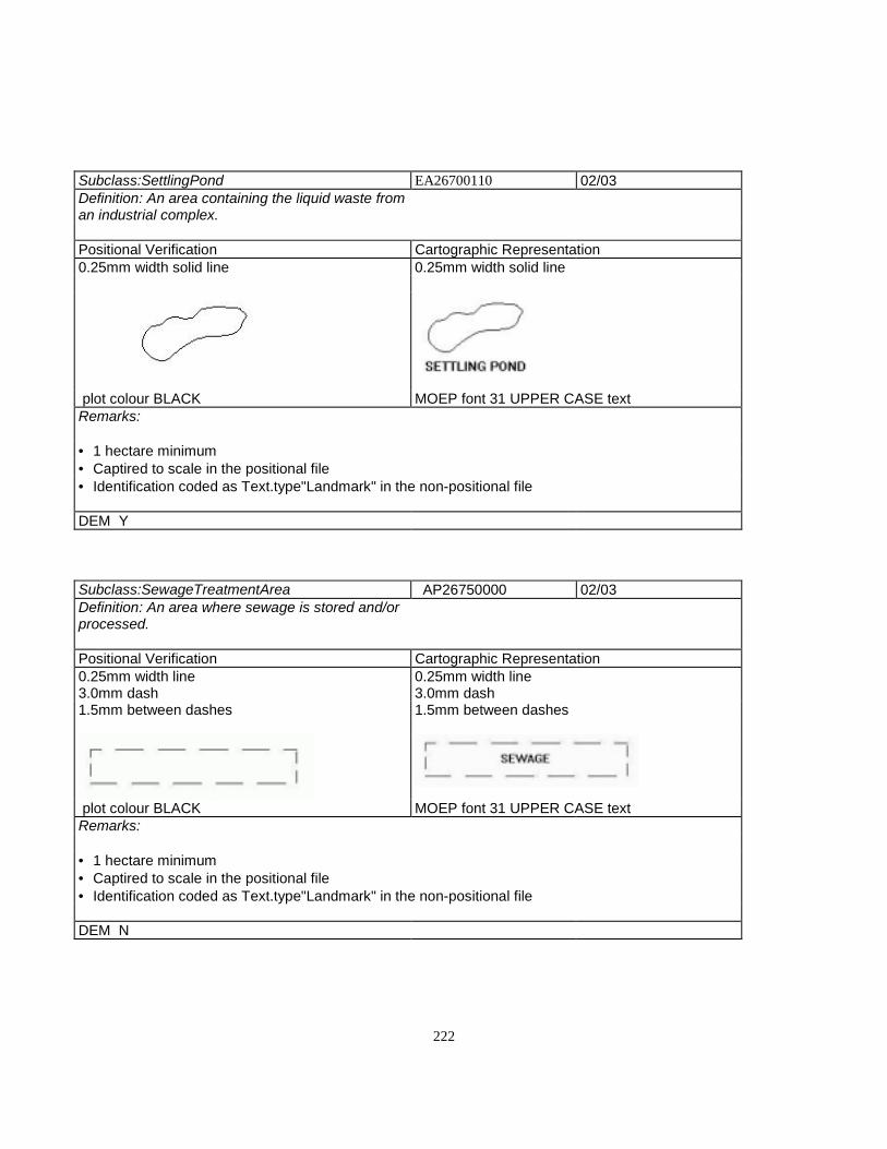
222
Subclass:SettlingPond EA26700110 02/03Definition: An area containing the liquid waste froman industrial complex.
Positional Verification Cartographic Representation0.25mm width solid line 0.25mm width solid line
plot colour BLACK MOEP font 31 UPPER CASE textRemarks:
• 1 hectare minimum• Captired to scale in the positional file• Identification coded as Text.type"Landmark" in the non-positional file
DEM Y
Subclass:SewageTreatmentArea AP26750000 02/03Definition: An area where sewage is stored and/orprocessed.
Positional Verification Cartographic Representation0.25mm width line 0.25mm width line3.0mm dash 3.0mm dash1.5mm between dashes 1.5mm between dashes
plot colour BLACK MOEP font 31 UPPER CASE textRemarks:
• 1 hectare minimum• Captired to scale in the positional file• Identification coded as Text.type"Landmark" in the non-positional file
DEM N
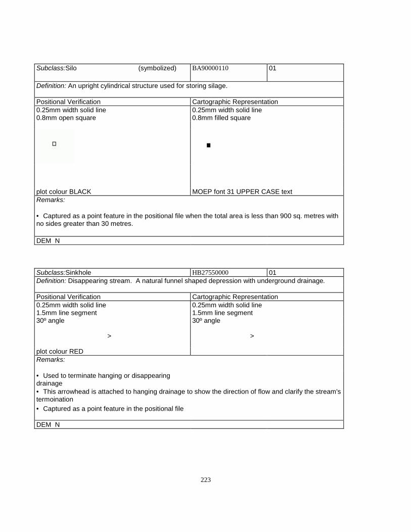
223
Subclass:Silo (symbolized) BA90000110 01
Definition: An upright cylindrical structure used for storing silage.
Positional Verification Cartographic Representation0.25mm width solid line 0.25mm width solid line0.8mm open square 0.8mm filled square
plot colour BLACK MOEP font 31 UPPER CASE textRemarks:
• Captured as a point feature in the positional file when the total area is less than 900 sq. metres withno sides greater than 30 metres.
DEM N
Subclass:Sinkhole HB27550000 01Definition: Disappearing stream. A natural funnel shaped depression with underground drainage.
Positional Verification Cartographic Representation0.25mm width solid line 0.25mm width solid line1.5mm line segment 1.5mm line segment30º angle 30º angle
> >
plot colour REDRemarks:
• Used to terminate hanging or disappearingdrainage• This arrowhead is attached to hanging drainage to show the direction of flow and clarify the stream'stermoination• Captured as a point feature in the positional file
DEM N

224
Subclass:SkiJump CL27750000 02/03
Definition: A ramp-like structure built on the side of a hill or mountain for the sport of ski-jumping.
Positional Verification Cartographic Representation0.25mm width solid line 0.25mm width solid line
MOEP font 31 UPPER CASE text MOEP font 31 UPPER CASE text
plot colour BLACKRemarks:
• Minimum length 50 metres• Captured to scale in the positional file• Identification coded as Text.type"Landform" in the non-positional file
DEM N
Subclass:SkiLift CL27800000 02/03
Definition: A cable device for transporting skiers up a hill.
Positional Verification Cartographic Representation0.25mm width solid line 0.25mm width solid line
0.5mm fadius filled circle30.0mm between circles
MOEP font 31 UPPER CASE textplot colour BLACKRemarks:
• Captured in the positional file• Identification coded as Text.type"Landmark" in the non-positional file
DEM N

225
Subclass:Slide (area outline) HB27900000 02/03
(area symbol) HB90000000 01Definition: A landform feature consisting of debris resulting from a sudden descent of a mass of earthor rock.
Positional Verification Cartographic RepresentationAREA OUTLINE AREA SYMBOL AREA OUTLINE AREA SYMBOL
0.25mm width line 7.0mm arrow 0.20mm width line 7.0mm arrow3.0mm dash 3.0mm "S" height 1.5mm dash 3.0mm "S" height
0.5mm dot 1.5mm between dashes
2.0mm from dash endto dot centre MOEP font 31 UPPER
CASE textMOEP font 31UPPER CASE text
plot colour BLACKRemarks:
• Area Outline - Longest dimension over 200 metres• Captured to scale in the positional file• AreaSymbol - Point feature• Arrow to show slide direction• Area symbol is captured in the non-positional file
DEM Y

226
Subclass:SmokestackChimney CG28300000 01
Definition: An upright flue through which combustion gasses and smoke are discharged into the air.
Positional Verification Cartographic Representation0.25mm width solid line 0.25mm width solid line1.0mm radius circle 1.0mm radius circle
MOEP font 31 UPPER CASE text
plot colour BLACKRemarks:
• When over 30 metres tall the height is captured as an attribute (MOEP type 05)• Captured as a point feature in the positional file• Identification coded as Text.type"Landmark" in the non-positional file
DEM N
Subclass:Snowshed DD283500000 02/03Definition: A roofed structure built over a road or railway in mountainous areas to prevent snowslidesfrom blocking a travelled route.
Positional Verification Cartographic Representation0.25mm width solid line SNOWSHED TERMINATOR
1.5mm filled dot 0.25mm width solid line 0.25mm widthsolid line1.6mm line length 0.7mm line ateach end
1.6mm betweem lines 45º angle
plot colour BLACKRemarks:
• Captured to scale in the positional file as a single line defining the apparent centre line• More than 40 metres in length plot to scale• Do not duplicate this feature as a road or railway
DEM N

227
Subclass:SportsField AL21900000 02/03
Definition: A hard or loose-surfaced area which sporting events take place.
Positional Verification Cartographic Representation0.25mm width line 0.25mm width line3.0mm dash 3.0mm dash1.5mm between dashes 1.5mm between dashes
MOEP font 31 UPPER CASE text plot colour BLACKRemarks:
• 1 hectare minimum• Capture to scale in the positional file• Identification coded as Text.type"Landmark" in the non-positional file
DEM N
Subclass:SportTrack AL22650110 02/03Definition: A track which is used for human competition as opposed to one used for racing horses,automobile, etc.
Positional Verification Cartographic Representation0.25mm width line 0.25mm width line
0.50mm between lines
MOEP font 31 UPPER CASE textplot colour BLACKRemarks:
• Captured to scale in the positional file• Identification coded as Text.type"Landmark" in the non-positional file
DEM N
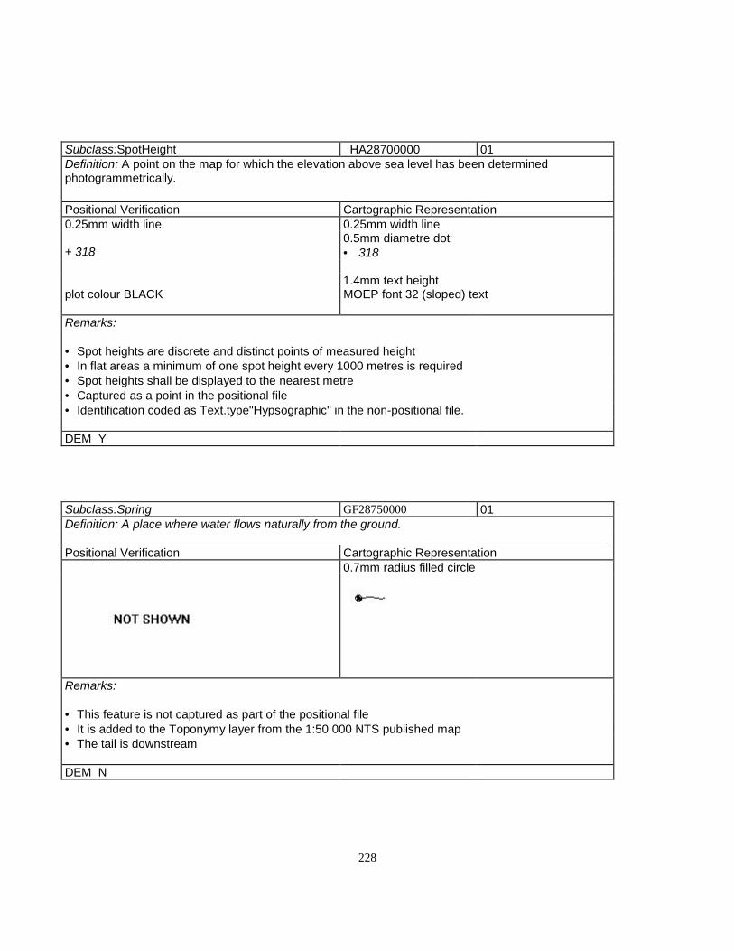
228
Subclass:SpotHeight HA28700000 01Definition: A point on the map for which the elevation above sea level has been determinedphotogrammetrically.
Positional Verification Cartographic Representation0.25mm width line 0.25mm width line
0.5mm diametre dot+ 318 • 318
1.4mm text heightplot colour BLACK MOEP font 32 (sloped) text
Remarks:
• Spot heights are discrete and distinct points of measured height• In flat areas a minimum of one spot height every 1000 metres is required• Spot heights shall be displayed to the nearest metre• Captured as a point in the positional file• Identification coded as Text.type"Hypsographic" in the non-positional file.
DEM Y
Subclass:Spring GF28750000 01Definition: A place where water flows naturally from the ground.
Positional Verification Cartographic Representation0.7mm radius filled circle
Remarks:
• This feature is not captured as part of the positional file• It is added to the Toponymy layer from the 1:50 000 NTS published map• The tail is downstream
DEM N
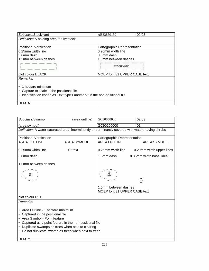
229
Subclass:StockYard AB33850150 02/03Definition: A holding area for livestock.
Positional Verification Cartographic Representation0.25mm width line 0.20mm width line3.0mm dash 3.0mm dash1.5mm between dashes 1.5mm between dashes
plot colour BLACK MOEP font 31 UPPER CASE textRemarks:
• 1 hectare minimum• Capture to scale in the positional file• Identification coded as Text.type"Landmark" in the non-positional file
DEM N
Subclass:Swamp (area outline) GC30050000 02/03
(area symbol) GC90200000 01Definition: A water-saturated area, intermittently or perminantly covered with water, having shrubs
Positional Verification Cartographic RepresentationAREA OUTLINE AREA SYMBOL AREA OUTLINE AREA SYMBOL
0.25mm width line "S" text 0.25mm width line 0.20mm width upper lines
3.0mm dash 1.5mm dash 0.35mm width base lines
1.5mm between dashes
1.5mm between dashesMOEP font 31 UPPER CASE text
plot colour REDRemarks:
• Area Outline - 1 hectare minimum• Captured in the positional file• Area Symbol - Point feature• Captured as a point feature in the non-positional file• Duplicate swamps as trees when next to clearing• Do not duplicate swamp as trees when next to trees
DEM Y

230
T
Subclass:TailingArea AP30300000 02/03Definition: An area containing the solid waste material prodiced in the minimg and milling of ore.
Positional Verification Cartographic Representation0.25mm width line 0.25mm width solid line3.0mm dash 1.0mm tick length1.5mm between dashes 0.20mm tick width
1.5mm between ticks
MOEP font 31 UPPER CASE textplot colour BLACKRemarks:
• 1 hectare minimum• Captured to scale in the positional file• Identification coded as Text.type"Landmark" in the non-positional file• Tailing pile or area are the same
DEM N

231
Subclass:TailingPond AP90300100 02/03Definition: A hydrologic feature used to separate, collect, ir filter waste material from an industrialcomplex.
Positional Verification Cartographic Representation0.25mm width solid line 0.35mm width solid line
plot colour BLACK
Remarks:
• Longest dimension over 25 metres• Captured to scale in the positional file
DEM Y
Subclass:Tank (to scale) EA30400000 02/03(symbolized) EA90000000 01Definition: A cylindrical receptical used for storage.
Positional Verification Cartographic RepresentationTO SCALE SYMBOLIZED TO SCALE SYMBOLIZED
0.25mm width solid line 0.7mm radius filledcircle
0.20mm width solid line 0.7mm radius filledcircle
• •
plot colour BLACK MOEP font 31 UPPERCASE text
Remarks:
• To Scale - Area lerger than 900 sq. metres• Captured in the positional file• Symbolized - Area less than 900 sq. metres• Captured in the positional file• Identification coded as Text.type"Landmark" in the non-positional file
DEM N
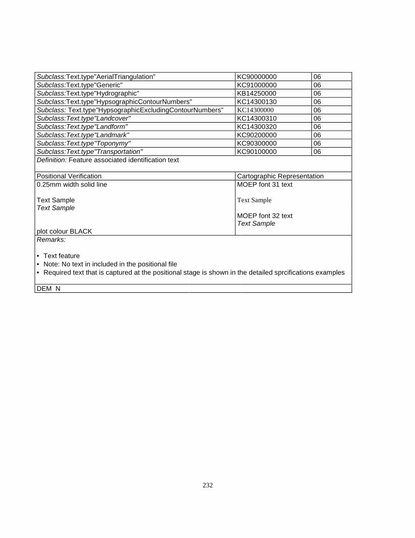
232
Subclass:Text.type"AerialTriangulation" KC90000000 06Subclass:Text.type"Generic" KC91000000 06Subclass:Text.type"Hydrographic" KB14250000 06Subclass:Text.type"HypsographicContourNumbers" KC14300130 06Subclass: Text.type"HypsographicExcludingContourNumbers" KC14300000 06Subclass:Text.type"Landcover" KC14300310 06Subclass:Text.type"Landform" KC14300320 06Subclass:Text.type"Landmark" KC90200000 06Subclass:Text.type"Toponymy" KC90300000 06Subclass:Text.type"Transportation" KC90100000 06Definition: Feature associated identification text
Positional Verification Cartographic Representation0.25mm width solid line MOEP font 31 text
Text Sample Text SampleText Sample
MOEP font 32 textText Sample
plot colour BLACKRemarks:
• Text feature• Note: No text in included in the positional file• Required text that is captured at the positional stage is shown in the detailed sprcifications examples
DEM N

233
Subclass:TollGate (to scale) DD31000000 02/03
(symbolized) DD91000000 01Definition: A barrier and/or booth on a transportation route at which a used fee is charged
Positional Verification Cartographic RepresentationTO SCALE SYMBOLIZED TO SCALE SYMBOLIZED
0.25mm width solid line 0.25mm width solidline
0.25mm width solid line 0.25mm width solidline
0.8mm open square 0.8mm filled square
plot colour BLACK
Remarks:
• Capture to scale in the positional file using the right hand rule when one side is > 30m. or the totalarea is > 900 sq. m.• Capture as a point in the positional file oriented to the true ground position when total area is < 900sq. m. with no sides > 30m.• Determine building dimensions by the outline of their roofs, including attached garages and multilevelparking.
DEM N
Subclass:Tower.type"Microwave" CC31150110 01Definition: A high structure that receives and transmits microwave communication signals.
Positional Verification Cartographic Representation0.25mm width solid line 0.25mm width
solid line2.0mm square 2.0mm square
plot colour BLACK MOEP font 31 UPPER CASE textRemarks:
• When over 30 meters tall, height is captured as an attribute (MOEP type 05)• Captured as a point feature in the positional file• Identification coded as Text.type"Landmarl" in the non-positional file
DEM N

234
Subclass:Tower.type"Transmission" CC90000000 01
Definition: A high structure supporting a transmission line built to provide clearance above thesurrounding objects or features.
Positional Verification Cartographic Representation0.25mm width solid line2.0mm square
plot colour BLACKRemarks:
• When over 30 meters tall, height is captured as an attribute (MOEP type 05)• Transmission towers are not plotted at the representational stage• Captured to scale in the positional file
DEM N
Subclass:Tower.type"Unspecified" CC31150000 01Definition: A high structure built to provide clearance above surrounding objects or features.
Positional Verification Cartographic Representation0.25mm width solid line 0.25mm width solid line2.0mm square 2.0mm square
plot colour BLACK MOEP font 31 UPPER CASE textRemarks:
• When over 30 metres tall, height is captured as an attribute (MOEP type 05)• Captured as a point feature in the positional file.
DEM N

235
Subclass:Trail DD31700000 02/03
Definition: A narrow path or route, not wide enough fot the passage of a four wheeled vehicle, suitablefor hiking or cycling. Park paths and boardwalks are considered trails.
Positional Verification Cartographic Representation0.25mm width line1.5mm dash 0.25mm width line1.5mm between dashes 2.0mm dash
1.0mm between dashes
plot colour BROWNRemarks:
• Minimum length 400 metres• Named features only• Captured in the positional file
DEM Y
Subclass:TrailerPark AN31950000 02/03Definition: An area dedicated to semi-perminant placement of mobile homes.
Positional Verification Cartographic Representation0.25mm width line 0.25mm width line3.0mm dash 3.0mm dash1.5mm between dashes 1.5mm between dashes
plot colour BLACK MOEP font 31 UPPER CASE textRemarks:
• Trailer homes will be shown as symbolized buildings except when part of a built-up area• All homes will be captured and included in the positional file but only an appropriate number will beincluded in the representatyional file• Captured to scale in the positional file• Identification coded as Text.type"Landmark" in the non-positional file
DEM N

236
Subclass:TransmissionLine EA16400120 02Definition: Primary - one or more cables for communications or power transmission.
Positional Verification Cartographic Representation0.25mm width line 0.20mm width line3.0mm dash 0.5mm radius filled circle0.5mm dot 3.0mm between circles2.0mm between dash end and dot centre2.0mm between dots
plot colour BLACKRemarks:
• Continuous over 4 kilometres minimum• Capture transmission line at tower base• No intermediate points captured between tower bases• Captured in the positional file.
DEM N

237
Subclass:Trestle DD93200000 02/03Definition: A braced framework erected along a travelled route to span a depression or opstacle.
Positional Verification Cartographic Representation0.25mm width solid line 0.35mm width line
TRESTLE DECK - 0.8mm between lines
TERMINATORS - 0.7mm line at ends45º angle
plot colour BLACKMOEP font 31 UPPER CASE text
Remarks:
• Captured to scale in the positional file as a single line defining the apparent centre line• More than 40 metres in length plot to scale• Capture width as type 05• Do not duplicate this feature as a road or railway
DEM N
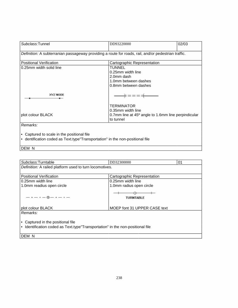
238
Subclass:Tunnel DD93220000 02/03
Definition: A subterranian passageway providing a route for roads, rail, and/or pedestrian traffic.
Positional Verification Cartographic Representation0.25mm width solid line TUNNEL
0.25mm width line2.0mm dash1.0mm between dashes0.8mm between dashes
TERMINATOR0.35mm width line
plot colour BLACK 0.7mm line at 45º angle to 1.6mm line perpindicularto tunnel
Remarks:
• Captured to scale in the positional file• dentification coded as Text.type"Transportation" in the non-positional file
DEM N
Subclass:Turntable DD32300000 01Definition: A railed platform used to turn locomotives.
Positional Verification Cartographic Representation0.25mm width line 0.25mm width line1.0mm readius open circle 1.0mm radius open circle
plot colour BLACK MOEP font 31 UPPER CASE textRemarks:
• Captured in the positional file• Identification coded as Text.type"Transportation" in the non-positional file
DEM N

239
USubclass:University (to scale) BE32400000 02
(symbolized) BE91000000 01Definition: An institution fot the highest level of learning, study, and research, and empowered to grantdegrees.
Positional Verification Cartographic RepresentationTO SCALE SYMBOLIZED TO SCALE SYMBOLIZED
0.25mm width solid line 0.25mm width solidline
0.25mm width solid line 0.25mm width solidline
0.8mm open square 0.8mm filled square
MOEP font 31 UPPERCASE text
MOEP font 31 UPPERCASE text
plot colour BLACKRemarks:
Capture to scale in the positional file using the right hand rule when one side is > 30m. or the total areais > 900 sq. m.Capture as a point in the positional file oriented to the true ground position when total area is < 900 sq.m. with no sides > 30m.Determine building dimensions by the outline of their roofs, including attached garages and multilevelparking.Place buildinf type identification as Text.type "Landmark" in the non-positional file, size determined bybuilding size
DEM N

240
V
Subclass:Vineyard JB32800000 02/03Definition: A plantation of grapevines.
Positional Verification Cartographic Representation0.25mm width solid line 0.25mm width solid line1.5mm dash 3.0mm dash1.5mm between dashes 1.5mm between dashes
plot colour BLACK MOEP font 31 UPPER CASE textRemarks:
• Minimum 1 hectare• Captured to scale in the positional file• Identification coded as Text.type"Landmark" in the non-positional file
DEM N
Subclass:VolcanicCrater HB07650130 02Definition: A bowl - shaped depression at the summit of or around the orifice of a volcano cone, hill.
Positional Verification Cartographic Representation3.0mm dash 0.20mm width tick1.5mm between dashes 1.0mm tick length
1.5mm between dashes
plot colour BLACK MOEP font 31 UPPER CASE textRemarks:
• Minimum 1 hectare• Captured to scale in the positional file• Identification coded as Text.type"Landmark" in the non-positional file
DEM Y

241
W
Subclass:Wall.type"Retaining" DD24600000 02/03Definition: A vertical structure constructed to enclose or divide an area.
Positional Verification Cartographic Representation0.25mm width solid line 0.25mm width solid line
1.25mm filled triangles4.0mm between triangles
plot colour BROWNRemarks:
• Minimum length 100 metres• Line - Low side• Captured to scale in the positional file
DEM Y

242
Subclass:WaterLevel(Dateof Photography) HA33100000 01
Definition: The height above mean sea level of a water surface.
Positional Verification Cartographic Representation0.25mm width solid line 0.25mm width solid line
+ 320 ± 320
plot colour BLACK MOEP font 32 UPPER CASE textRemarks:
• Lakes with shortest side over 300 metres require a water level• Capture as a point feature in the positional file• dentification coded as Text,.type"Hydrographic" in the non-positional file
DEM N
Subclass:WeighScale(building) (to scale) CG33250000 02/03(symbolized) CG33250100 01Definition: A facility dedicated to the weighing of commercial vehicles.
Positional Verification Cartographic RepresentationTO SCALE SYMBOLIZED TO SCALE SYMBOLIZED0.25mm width solid line 0.25mm width solid line 0.25mm width solid line 0.25mm width solid
line0/8mm open square 0.8mm filled square
plot colour BLACK
Remarks:
• Capture to scale in the positional file using the right hand rule when one side is > 30m. or the totalarea is > 900 sq. m.• Capture as a point in the positional file oriented to the true ground position when total area is < 900sq. m. with no sides > 30m.• Determine building dimensions by the outline of their roofs, including attached garages and multilevelparking.
DEM N

243
Subclass:Wooded Area JA33750000 02/03Definition: A land area which is at least six (6) percent covered with trees that are two (2) metres ormore in height.
Positional Verification Cartographic Representation0.25mm width solid line 0.25mm width solid line
1.0mm scallop
plot colour GREEN MOEP font 31 UPPER CASE textRemarks:
• Capture to scale in the positional file• minimum area 1 hectare• Vertical accuracy 20 metres• The intent is to show all wooded areas that have a crown closure of 6% or greater and cover an areagreater than 1.0 hectare• Areas that are evenly distributed with wooded area polygons may be grouped together if they cover60% of the total area in question• Wooded area boundaries along rightofways (i.e., Roads, Transmission lines etc.) will not be capturedunless the rightofway is 40 metrws or greater in width• Naturally occurring or man-made lcearings of 0.1 hectares or greater that are enclosed within woodedareas as defined above will be shown as "holes" in the wooded area polygon, i.e. the lines bounding thenon-wooded area are coded as wooded area features with the forest to the right of the line and theclearing to the left of the line• Particular care will be taken to show the true shape of the non-wooded areas in extensive woodedareas• Forestry cut blocks which do not show obvious signs of substantial regeneration (2 metres or more)will be shown as non-wooded areas• Scrub and sparse trees of less than 6% coverage will be shown as non-wooded areas
DEM N
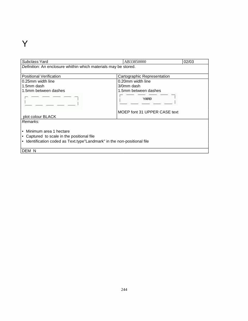
244
Y
Subclass:Yard AB33850000 02/03Definition: An enclosure whithin which materials may be stored.
Positional Verification Cartographic Representation0.25mm width line 0.20mm width line1.5mm dash 3/0mm dash1.5mm between dashes 1.5mm between dashes
MOEP font 31 UPPER CASE text plot colour BLACKRemarks:
• Minimum area 1 hectare• Captured to scale in the positional file• Identification coded as Text.type"Landmark" in the non-positional file
DEM N
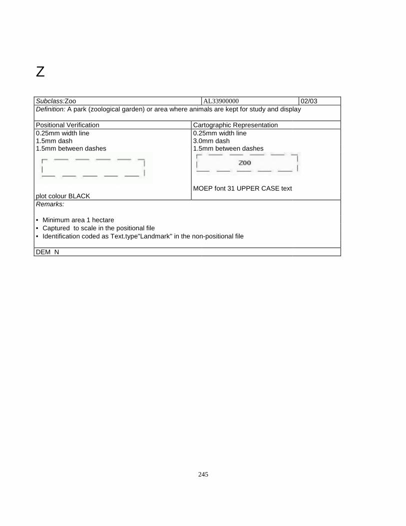
245
Z
Subclass:Zoo AL33900000 02/03Definition: A park (zoological garden) or area where animals are kept for study and display
Positional Verification Cartographic Representation0.25mm width line 0.25mm width line1.5mm dash 3.0mm dash1.5mm between dashes 1.5mm between dashes
MOEP font 31 UPPER CASE textplot colour BLACKRemarks:
• Minimum area 1 hectare• Captured to scale in the positional file• Identification coded as Text.type"Landmark" in the non-positional file
DEM N

246
PART III Detailed Business Object Specifications

247
Detailed Business Object Specifications
The 1: 20 000 Baseline datasets contain spacial and feature aidentification elements only. No associated textual databaseinformation.Appendices

248
PART IV Appendices
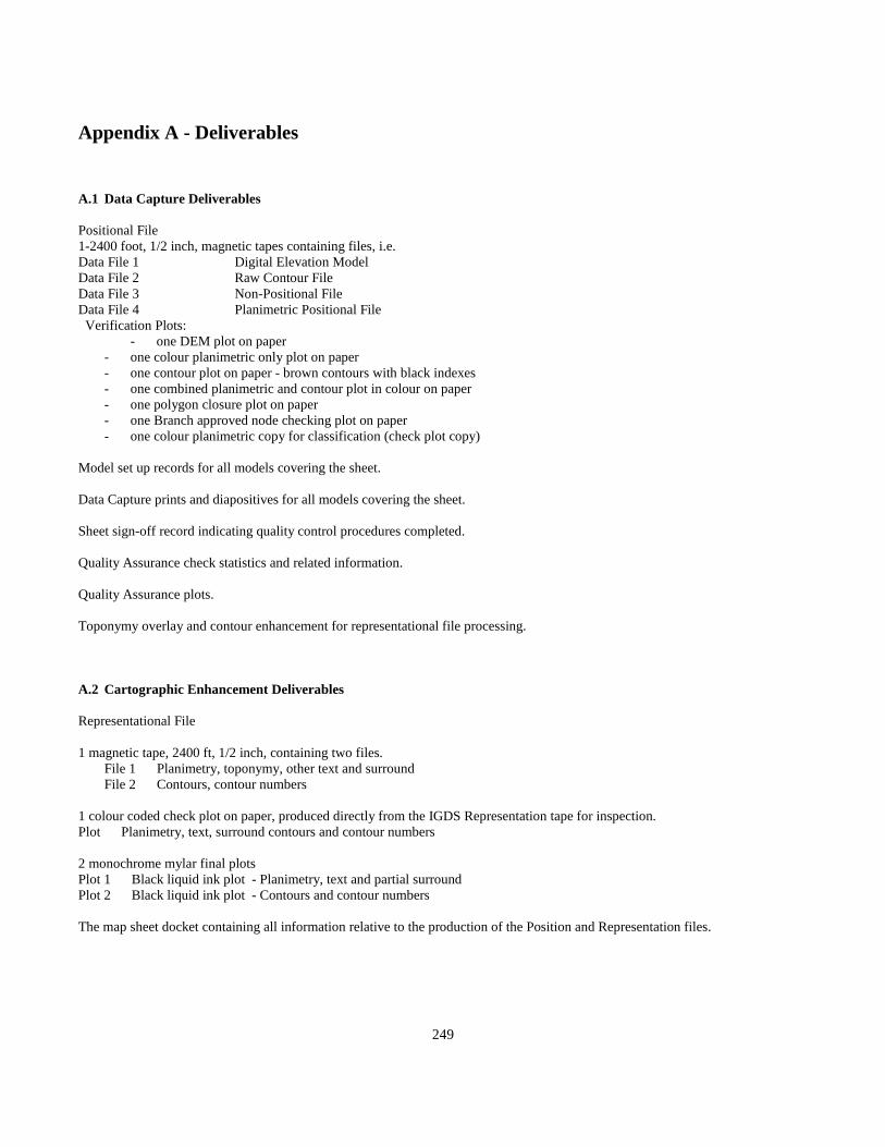
249
Appendix A - Deliverables
A.1 Data Capture Deliverables
Positional File1-2400 foot, 1/2 inch, magnetic tapes containing files, i.e.Data File 1 Digital Elevation ModelData File 2 Raw Contour FileData File 3 Non-Positional FileData File 4 Planimetric Positional File Verification Plots: - one DEM plot on paper
- one colour planimetric only plot on paper- one contour plot on paper - brown contours with black indexes- one combined planimetric and contour plot in colour on paper- one polygon closure plot on paper- one Branch approved node checking plot on paper- one colour planimetric copy for classification (check plot copy)
Model set up records for all models covering the sheet.
Data Capture prints and diapositives for all models covering the sheet.
Sheet sign-off record indicating quality control procedures completed.
Quality Assurance check statistics and related information.
Quality Assurance plots.
Toponymy overlay and contour enhancement for representational file processing.
A.2 Cartographic Enhancement Deliverables
Representational File
1 magnetic tape, 2400 ft, 1/2 inch, containing two files. File 1 Planimetry, toponymy, other text and surround
File 2 Contours, contour numbers
1 colour coded check plot on paper, produced directly from the IGDS Representation tape for inspection.Plot Planimetry, text, surround contours and contour numbers
2 monochrome mylar final plotsPlot 1 Black liquid ink plot - Planimetry, text and partial surroundPlot 2 Black liquid ink plot - Contours and contour numbers
The map sheet docket containing all information relative to the production of the Position and Representation files.

250
A.3 Edit Notations
A standard set of edit notation based on the Federal system will be used based on a combination of colours, symbology and text asshown below. This system will be used by all editors in order that there will be no ambiguity as to the meaning of any edit notation.
Symbology
^ = AddX = deleteAMC = Amend CodeAME = Amend ElevationAMO = Amend OrientationAMP = Amend Position of FeatureAMR = Amend to ReadTu = Touch upColourRED = Positional Contractor Quality CheckORANGE = Representational Contractor Quality CheckPURPLE = Branch Quality Audit
A.4 Procedures for Marking Contractor Toponymy Submissions
1. All Branch markings and corrections will be done in PURPLE as indicated in the edit notation colours.
2. Omitted names will be placed by Branch inspectors, as they should appear in the Representation submission.
3. The placement of names that require moving will be indicated with a line, this line will roughly indicate the beginning and endof a word with ticks.
4. The first letter of words to be placed will generally be bottom left justified. If proper name placement is dependent on theaccurate placement of the end of a word, the last letter of the word will be printed indicating right justification.
5. Name placement in linear lake and wide doubleline river features will be indicated with a line having centre justification.
6. The moving of spot heights for clarity and to avoid conflict will be indicated with a line (see 3 above) and will be arrowed fromthe current position to the new position.
7. Text to be deleted will be crossed out with an X as indicated in the edit notation symbology.
8. Each contour label in a set of contour elevations will be indicated with a pair of ticks.

251
A.5 General Deliverables
Contractors will submit Operating Procedures for Branch approval that will include the following:
- production diagram- resume of all production personnel- photogrammetric equipment annual calibration reports- quality assurance procedures

252
Appendix B Representation File Editing Guidelines (Cartographic Enhancement)

253
Appendix B - Cartographic EnhancementB.1 General
These guidelines apply to the production of the Representational file and the map separations listed in Part I, Section 3.5.
Notwithstanding any instructions given here, all edits of the Representational File will conform to good cartographic practices.
B.2 Hierarchical Order for Feature Positioning
The Representational File will be edited in such a manner that the final product is cartographically acceptable. Every effort will bemade to avoid conflict of data, with the restriction that survey data, survey control monuments, etc., will not be positionally edited.
These features are listed in the hierarchical order that will dictate precedence in feature positioning on the Representational File.(See B.4)
The following general rules for placement of symbology will further clarify this procedure.
B.2.1 Point Symbol (other than survey control)These symbols should not normally be moved, unless there is no other choice
B.2.2 Linear SymbologyMay be moved from the actual location, or if two features at the same level on the hierarchy conflict, they may be moved relative toeach other equally from the actual position.
B.2.3 Area SymbologyThose features which define an area may have one or more sides adjusted for clarity.
B.2.4 Textual InformationText, such as cultural, topographic and hydrographic are the most flexible features for re-positioning.
B.3 Specific Editing Situations
All features including contours will be removed from inside primary and secondary road number symbols.
All features including contours will be removed from inside utility symbols.
Hydrography, and where applicable, roads and railways will be removed from between the two sides of a bridge symbol or feature.
Area symbols such as marsh and swamp may be scaled by a factor of 0.75 to permit placement within the feature boundary. If thescaled symbol cannot be placed inside the feature, it will be placed adjacent to the feature.
B.4 Representational Hierarchy 1. Lakes and intermittent lakes. 2. Major rivers and streams. 3. Other streams. 4. Railroads and roads, cutlines. 5. Other hydrography (marshes, swamps) See B.4.1 other features. 6. Buildings and built-up areas. 7. Other cultural detail. 8. Tree line.

254
B.4.1 Hierarchy of Other Features 1. Glaciers 2. Icefields 3. Moraine 4. Scree 5. Marsh 6. Swamp
B.5 Basic Lettering Standards
B.5.1 Lettering Style LEROY (Font 31,33 = Vertical, Font 32,34 = Italic)
B.5.2 Range of Text Sizes to be Used (Generic text)
These text sizes are to be used with the generic text, such as rapids, falls, scree, moraine, pit, etc.
LEROY 60 WT 0 = 1.4mm80 WT 1 = 1.8mm100 WT 1 = 2.2mm
B.5.3 Basic Lettering Guidelines ! Text associated with symbolized features other than hydrographic features will be capitals only. ! Text associated with natural symbolized hydrographic features will be U/L Italic as Rapids.The type size of labels may vary depending on the size of the area of length of feature. ! Labels will be in full, space permitting. However, abbreviations will be accepted if doing so keeps the labelwithin the feature, when specifications require it.Labels should read from the bottom of the sheet where possible. When the angle of inclination of the linear feature, i.e.conveyor, increases the text will be placed above the feature (when practical) reading from either side of the sheet.Do not place text so that it appears over vertical.

255
B.6 Guidelines Regarding Text Placement
Labels along linear features, i.e. CONVEYOR, will be placed above and parallel to the feature where possible. Labels parallel to theneat line with one end of the word immediately adjacent to the central area of the feature.
Labels inside features, i.e. POOL, will be parallel to the bottom side (relative to the neat line) of the feature.
Labels of large irregular area outlines, i.e. PIT, STORAGE AREA, will be parallel to neat line, and, where practical, within the areaoutline.
Labels outside features, i.e. LOOKOUTS, will be parallel to the neat line.
Railway names will be shown unabbreviated once per map sheet where possible, up to a maximum of 50mm spacing betweenconsecutive words in the name. Abbreviations (e.g. BCR, CPR, etc.) will be used where space does not permit use of the full name,and must be shown twice for railways extending over 250mm on the map sheet.

256
Appendix C Geographical Nomenclature (Toponymy)
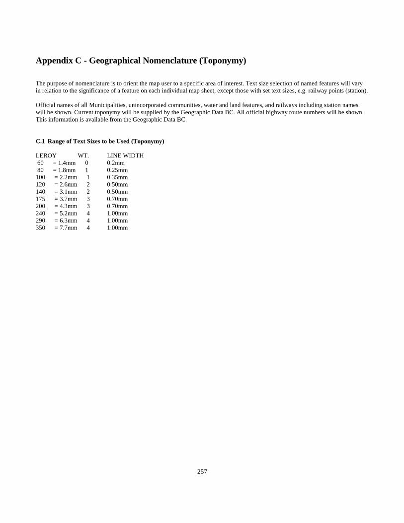
257
Appendix C - Geographical Nomenclature (Toponymy)
The purpose of nomenclature is to orient the map user to a specific area of interest. Text size selection of named features will varyin relation to the significance of a feature on each individual map sheet, except those with set text sizes, e.g. railway points (station).
Official names of all Municipalities, unincorporated communities, water and land features, and railways including station nameswill be shown. Current toponymy will be supplied by the Geographic Data BC. All official highway route numbers will be shown.This information is available from the Geographic Data BC.
C.1 Range of Text Sizes to be Used (Toponymy)
LEROY WT. LINE WIDTH 60 = 1.4mm 0 0.2mm 80 = 1.8mm 1 0.25mm100 = 2.2mm 1 0.35mm120 = 2.6mm 2 0.50mm140 = 3.1mm 2 0.50mm175 = 3.7mm 3 0.70mm200 = 4.3mm 3 0.70mm240 = 5.2mm 4 1.00mm290 = 6.3mm 4 1.00mm350 = 7.7mm 4 1.00mm

258
Toponymy Letter Spacing Guide
(Scale Approximate)

259

260
C.2 - Guidelines for Land Features
C.2.1 Land Features
Lettering of land features will be vertical in capitals unless otherwise specified. All text sizes are shown as Leroy Templatenumbers. (See Section B.5).
Large Area Land Features
RIDGE, GULCH, FLATS, CANYON 120, 140 (LEROY)BLUFF 100, 120 (LEROY)
Mountain Range Names
Area Involved WHOLE SHEET 200 (LEROY) HALF SHEET 175 (LEROY) MINIMUM 140 (LEROY)
Mountains Peaks
MOUNT, MOUNTAIN, PEAK (abbreviate to MT and MTN) 120 (LEROY)
The guidelines for applications for nomenclature to mountain ranges:When a range is generally in ridge or spline form then the name will be placed along the backbone or height of land. Whenmountain range consists of several individual summits over a broad area with no clearly defined centre line, and then nameplacement will be centralized in area involved and parallel to the bottom neat line.
C.2.2 - Cities, Towns, Villages, Settlements, Localities, Railway Points, Post Offices
All of these will be in capitals except for Railway Points, which will be in upper and lower case.
Measured in Square Kilometres:0 - 5, 120 (LEROY) (Railway Points Max 120)
5 - 10, 140 (LEROY) (Localities Max 140) 10 - 15, 175 (LEROY) 15 - 25, 240 (LEROY) 25 - 240 (LEROY)
City, town and village names will be positioned within the populated areas when space permits. The text will be positioned to avoidclash with planimetric map detail. This can usually be accomplished by positioning the label over parks, playing fields, storageareas, and hatched areas where no significant detail will be obstructed.
NOTE: Where the railway point (station), Post Offices name is the same as the Municipality or unincorporated community name inwhich it is situated, the point (station), Post Offices name will not be shown.

261
C.2.3 Airports (Airfields, Airstrips)
Labelled 120 LEROY for single strip (capitals)Labelled 140 LEROY for multiple strips (capitals)
C.2.4 Boundary Names
ALBERTA, ALASKA (USA), WASHINGTON (USA), YUKON TERRITORY (capitals)
Labelled 120 LEROY (capitals)
C.2.5 Land Features Within Water Areas
Large land area features, i.e. islands, peninsulas, etc. use same guide as given for water features, (see C.3.4) Small islands 0 - 10square kilometres use U/L 60, 120 LEROY.
NOTE: Text size will vary depending on density of detail and/or Toponymy in immediate area.
POINT NAMES 120 LEROYROCK, ISLET 100 LEROYISLETS 100, 120 LEROY
C.3 - Guidelines for Nomenclature of Water Features
Water features, i.e. pond, lake, etc., are labelled in sloped (italic) lettering.
C.3.1 Coastal Features
Open ended coastal drainage feature, i.e. passage, channel, strait. When entire feature appears on map, mark each end; create thecentre line through the feature, divide in thirds and place name as per guidelines for creeks and rivers. When only a portion offeature appears on sheet, create centre line from mapped end of feature to neatline and divide this length in thirds.
C.3.2 Closed Ended Water Features
(i.e. COVE, ARM, SOUND, INLET, HARBOUR, BAY)
When length of feature is more than 3 times the width then place name as per guidelines for open ended waterways, i.e. inlets, arms,harbours. When the feature is more regular than the 3 to 1 ratio, then the name will be placed centrally parallel to the bottom neatline.
C.3.3 Guidelines for Application fo Nomenclature to Drainage
1. All named rivers (double-line and single-line) will be capitals.
2. Creeks are labelled in U/L lettering, regardless whether single or double line.
262
C.3.4 Text Size Selection Relative to Water Feature Area
General guidelines for text size selection relative to water features in terms of area involved.
At Map Scale: 1:20 0000 - 100 Hectares 120 LEROY U/L100 - 800 Hectares 140 LEROY CAPS800 - 1/16 SHEET AREA 175 LEROY CAPS1/16 - 1/4 SHEET AREA 200 LEROY CAPS1/4 - 1/2 SHEET AREA 240 LEROY CAPS2 - ENTIRE SHEET AREA 290 LEROY CAPS
Optimum name placement will be within the feature; either straddling the main centre line of an elongated lake or parallel to theneat line centrally located when space permits.
C.3.5 General Guidelines fot Text Size Selection Relative to Water Features in Term of Length Involved
Rivers and creeks length of feature at map scale. 0 - 1000m = 100 LEROY1000 - 2000m = 120 LEROY2000 - 4000m = 140 LEROY4000 - 6000m = 175 LEROY6000 - 8000m = 200 LEROY8000m - m = 240 LEROY
C.3.6 Name Placement Relative to Creek, River and Other Fresh Water Irregular Drainage Patterns
Name placement will be above the feature relative to the bottom of the sheet, unless minimal length of feature appearing on sheetand lettering size required make it prohibitive, or when dense planimetric detail above feature makes name positioning impractical.
Then, placing the name under the feature can be considered.
Measure the length of the feature and divide it in thirds. The name will be placed generally centred over the first third mark, and theRiver (Creek) word will be centred over the second third mark. When planimetric or draining detail conflict at this positioning,attempt to alleviate by moving names closer together, not further apart.
The optimum space between the feature and the bottom of the words is 1/2 to 1 1/2 times the selected text height.
NOTE: Abbreviations will be accepted when length of feature is insufficient to apply label according to specification guidelines.Instances may occur when adherence to specification guidelines may prove unfeasible due to conflict with significant detail. Inthese cases, abbreviations of creek, lake or river should be the first option considered.

263

264
Appendix D Surround Information

265
Appendix D - Surround InformationD.1 Cartographic Separations
Any or all of the following hard copy cartographic separations may be specified for each project. These plotted separations willbe used to produce the map layers and combinations as required.
Separation 1 - Master Surround and Legend Information Separation 2 - Planimetry (Drainage, Cultural, Toponomy) Separation 3 - Contours Separation 7 - Orthophoto
D.2 Master Surround
D.2.1 Master Surround
The Master Surround provides the standard border for 1:1 000/1:500 map sheets produced in accordance with the British ColumbiaGeographic System of Mapping.
Within the surround area, data pertinent to the specific map sheet (variable data) and data specific to the project as a whole(non-variable data) is displayed to assist the map user.
The non-variable data is stored in IGDS Design file format within the Branch's Intergraph environment.
All data is positioned within the file in relation to the fixed origin located beyond the bottom-left corner. This data constitutes theMaster Surround. Copies of the Master Surround data are available through the Branch upon request.
D.2.2 Variable Data includes:
a) Sheet number b) Adjoining sheet number c) Magnetic declination data d) UTM zone number e) Type of data available in digital format f) Photo scale, date flown and year of map production
This data is placed into the respective data field during Representation File Processing. Those items listed at a - e inclusive, areplaced by a software subroutine invoked by keying in the Map sheet Number. Item f is keyed in individually.
All other variable data is to appear in the Planimetric Representation file.

266
D.2.3 Non-Variable Data includes:
I) Standard map sheet border ii) Scale bar and representation fraction iii) Map projection and geodetic datum note iv) B.C. Government logo v) Contour information and note<R>Re: Datum for elevation vi) Legend vii) Data fields at fixed distance from the origin and is an integral part of the Master Surround data file.
D.3 Legend
The legend provides samples of the symbology used to depict those details most commonly occurring on the 1:1 000/1:500 mappingproduced under Municipal GIS initiative.

267
Appendix E Dictionary of Abbreviations
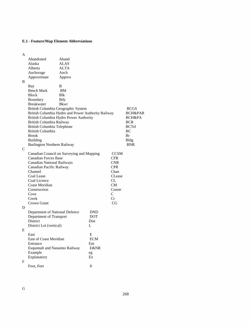
268
E.1 - Feature/Map Element Abbreviations
A Abandoned Aband Alaska ALAS Alberta ALTA Anchorage Anch Approximate ApproxB Bay B Bench Mark BM Block Blk Boundary Bdy Breakwater Bkwr British Columbia Geographic System BCGS British Columbia Hydro and Power Authority Railway BCH&PAR British Columbia Hydro Power Authority BCH&PA British Columbia Railway BCR British Columbia Telephone BCTel British Columbia BC Brook Br Building Bldg Burlington Northern Railway BNRC Canadian Council on Surveying and Mapping CCSM Canadian Forces Base CFB Canadian National Railways CNR Canadian Pacific Railway CPR Channel Chan Coal Lease CLease Coal Licence CL Coast Meridian CM Construction Constr Cove C Creek Cr Crown Grant CGD Department of National Defence DND Department of Transport DOT District Dist District Lot (vertical) LE East E East of Coast Meridian ECM Entrance Ent Esquimalt and Nanaimo Railway E&NR Example eg Explanatory ExF Foot, Feet ft
G

269
Glacier Gl Government Govt Group Gp Gulf GlH Harbour Hr Head, Headland Hd Height Ht High Water HW Highway HwyI Idaho ID Indian Affairs Surveys Records IASR Indian Reserve IR Inlet In International Boundary Int Bdy Islands Is Island I Islet, Islets It, Its InterGraph Display Systems IGDSJ Junction JctK Kilometre kmL Lagoon Lag Lake, Lakes L, Ls Land Title Office LTO Landing Ldg Latitude Lat Longitude Long Low Water LWM Mineral Claim MC Metre m Monument Mon Mount Mt Mountain, Mountains Mtn, Mtns Montana MONT Municipality MunN Narrows Nrs National NAT Natural (gas) Nat North N North American Datum 1927 NAD/27 North American Datum 1983 NAD/83 Northwest Territories NWT Number No
P Passage Pass Peak Pk Peninsula Pen Plan Number (Land Title Office) Pl Point Pt Provincial Prov

270
R Railway Rly Range (Township Range) (vertical) Rg Reef, Reefs Rf, Rfs Reference Ref Regional Surveyor British Columbia RSBC Reserve Res Right of Way R/W River R Road, Roadstead Rd Rock, Rocky Rk Rocks RksS Saint St School Sch Section Sec Sketch Sk Sound Sd South S Sports Field SpFld Station Sta Statutory Right of Way SR/W Strait Str Street St Sub Lot SL Suburban Sub
T Township Tp
U
United States, United States of America USA Universal Transverse Mercator UTMW Washington WASH West W West of Coast Meridian WCMY Yukon Territory YT

271
Appendix F IGDS Level/Colour Guidelines

272
Appendix F – IGDS Level/Colour Guidelines
F.1 Feature Code - Feature Name - Level/Colour Correlation
All digital data provided under this specification is uniquely identified by a feature object name that can be correlated to a featurecode. Graphic display systems such as Intergraph do not allow for the inclusion of a unique alphanumeric code without theattachment of an external database. To provide feature uniqueness within such an environment, features have been assigned acombination of IGDS level (layer) and colour. This table lists the features by feature code and provides guidelines for levelplacement and colour assignment.
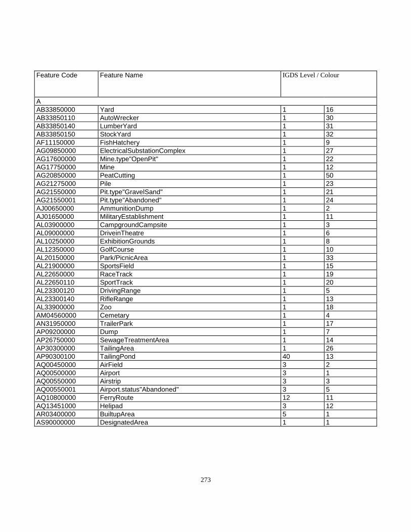
273
Feature Code Feature Name IGDS Level / Colour
AAB33850000 Yard 1 16AB33850110 AutoWrecker 1 30AB33850140 LumberYard 1 31AB33850150 StockYard 1 32AF11150000 FishHatchery 1 9AG09850000 ElectricalSubstationComplex 1 27AG17600000 Mine.type"OpenPit" 1 22AG17750000 Mine 1 12AG20850000 PeatCutting 1 50AG21275000 Pile 1 23AG21550000 Pit.type"GravelSand" 1 21AG21550001 Pit.type"Abandoned" 1 24AJ00650000 AmmunitionDump 1 2AJ01650000 MilitaryEstablishment 1 11AL03900000 CampgroundCampsite 1 3AL09000000 DriveinTheatre 1 6AL10250000 ExhibitionGrounds 1 8AL12350000 GolfCourse 1 10AL20150000 Park/PicnicArea 1 33AL21900000 SportsField 1 15AL22650000 RaceTrack 1 19AL22650110 SportTrack 1 20AL23300120 DrivingRange 1 5AL23300140 RifleRange 1 13AL33900000 Zoo 1 18AM04560000 Cemetary 1 4AN31950000 TrailerPark 1 17AP09200000 Dump 1 7AP26750000 SewageTreatmentArea 1 14AP30300000 TailingArea 1 26AP90300100 TailingPond 40 13AQ00450000 AirField 3 2AQ00500000 Airport 3 1AQ00550000 Airstrip 3 3AQ00550001 Airport.status"Abandoned" 3 5AQ10800000 FerryRoute 12 11AQ13451000 Helipad 3 12AR03400000 BuiltupArea 5 1AS90000000 DesignatedArea 1 1
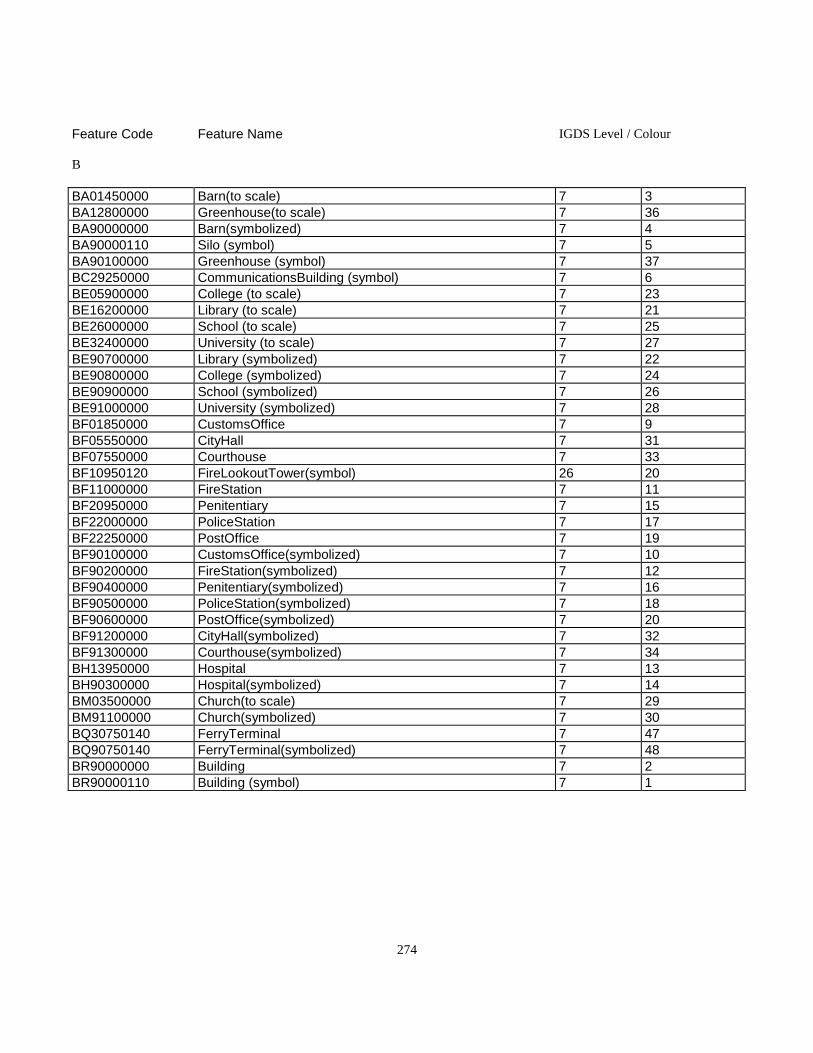
274
Feature Code Feature Name IGDS Level / Colour
B
BA01450000 Barn(to scale) 7 3BA12800000 Greenhouse(to scale) 7 36BA90000000 Barn(symbolized) 7 4BA90000110 Silo (symbol) 7 5BA90100000 Greenhouse (symbol) 7 37BC29250000 CommunicationsBuilding (symbol) 7 6BE05900000 College (to scale) 7 23BE16200000 Library (to scale) 7 21BE26000000 School (to scale) 7 25BE32400000 University (to scale) 7 27BE90700000 Library (symbolized) 7 22BE90800000 College (symbolized) 7 24BE90900000 School (symbolized) 7 26BE91000000 University (symbolized) 7 28BF01850000 CustomsOffice 7 9BF05550000 CityHall 7 31BF07550000 Courthouse 7 33BF10950120 FireLookoutTower(symbol) 26 20BF11000000 FireStation 7 11BF20950000 Penitentiary 7 15BF22000000 PoliceStation 7 17BF22250000 PostOffice 7 19BF90100000 CustomsOffice(symbolized) 7 10BF90200000 FireStation(symbolized) 7 12BF90400000 Penitentiary(symbolized) 7 16BF90500000 PoliceStation(symbolized) 7 18BF90600000 PostOffice(symbolized) 7 20BF91200000 CityHall(symbolized) 7 32BF91300000 Courthouse(symbolized) 7 34BH13950000 Hospital 7 13BH90300000 Hospital(symbolized) 7 14BM03500000 Church(to scale) 7 29BM91100000 Church(symbolized) 7 30BQ30750140 FerryTerminal 7 47BQ90750140 FerryTerminal(symbolized) 7 48BR90000000 Building 7 2BR90000110 Building (symbol) 7 1

275
Feature Code Feature Name IGDS Level / Colour
C
CC31150000 Tower.type"Unspecified" 26 16CC31150110 Tower.type"Microwave" 26 19CC90000000 Tower.type"Transmission" 26 2CG03550000 Burner 7 44CG07600000 Crane.type"Permanent" 7 49CG09100000 Drydock 12 23CG12150000 Well.type"Gas" 26 34CG19600000 Well.type"Oil" 26 3CG28300000 SmokestackChimney 7 43CG33250000 WeighScale 7 50CG33250100 WeighScale(symbolized) 7 51CL27750000 SkiJump 7 45CL27800000 SkiLift 26 7CQ00300000 AerialCableway 19 4CQ01850000 Beacon 12 9CQ06400000 Conveyor 1 28CQ08850130 FerryDock 12 10CQ08850160 MarinaYaghtClub 12 15CQ16350000 Lighthouse 12 8CQ21250000 Pier/Wharf 12 6CQ90000120 Pier/Wharf(symblized) 12 3CR10750000 Fence 26 8
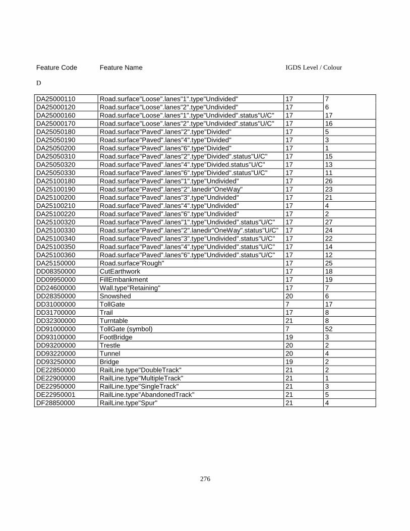
276
Feature Code Feature Name IGDS Level / Colour
D
DA25000110 Road.surface"Loose".lanes"1".type"Undivided" 17 7DA25000120 Road.surface"Loose".lanes"2".type"Undivided" 17 6DA25000160 Road.surface"Loose".lanes"1".type"Undivided".status"U/C" 17 17DA25000170 Road.surface"Loose".lanes"2".type"Undivided".status"U/C" 17 16DA25050180 Road.surface"Paved".lanes"2".type"Divided" 17 5DA25050190 Road.surface"Paved".lanes"4".type"Divided" 17 3DA25050200 Road.surface"Paved".lanes"6".type"Divided" 17 1DA25050310 Road.surface"Paved".lanes"2".type"Divided".status"U/C" 17 15DA25050320 Road.surface"Paved".lanes"4".type"Divided.status"U/C" 17 13DA25050330 Road.surface"Paved".lanes"6".type"Divided".status"U/C" 17 11DA25100180 Road.surface"Paved".lanes"1".type"Undivided" 17 26DA25100190 Road.surface"Paved".lanes"2".lanedir"OneWay" 17 23DA25100200 Road.surface"Paved".lanes"3".type"Undivided" 17 21DA25100210 Road.surface"Paved".lanes"4".type"Undivided" 17 4DA25100220 Road.surface"Paved".lanes"6".type"Undivided" 17 2DA25100320 Road.surface"Paved".lanes"1".type"Undivided".status"U/C" 17 27DA25100330 Road.surface"Paved".lanes"2".lanedir"OneWay".status"U/C” 17 24DA25100340 Road.surface"Paved".lanes"3".type"Undivided".status"U/C" 17 22DA25100350 Road.surface"Paved".lanes"4".type"Undivided".status"U/C" 17 14DA25100360 Road.surface"Paved".lanes"6".type"Undivided".status"U/C" 17 12DA25150000 Road.surface"Rough" 17 25DD08350000 CutEarthwork 17 18DD09950000 FillEmbankment 17 19DD24600000 Wall.type"Retaining" 17 7DD28350000 Snowshed 20 6DD31000000 TollGate 7 17DD31700000 Trail 17 8DD32300000 Turntable 21 8DD91000000 TollGate (symbol) 7 52DD93100000 FootBridge 19 3DD93200000 Trestle 20 2DD93220000 Tunnel 20 4DD93250000 Bridge 19 2DE22850000 RailLine.type"DoubleTrack" 21 2DE22900000 RailLine.type"MultipleTrack" 21 1DE22950000 RailLine.type"SingleTrack" 21 3DE22950001 RailLine.type"AbandonedTrack" 21 5DF28850000 RailLine.type"Spur" 21 4
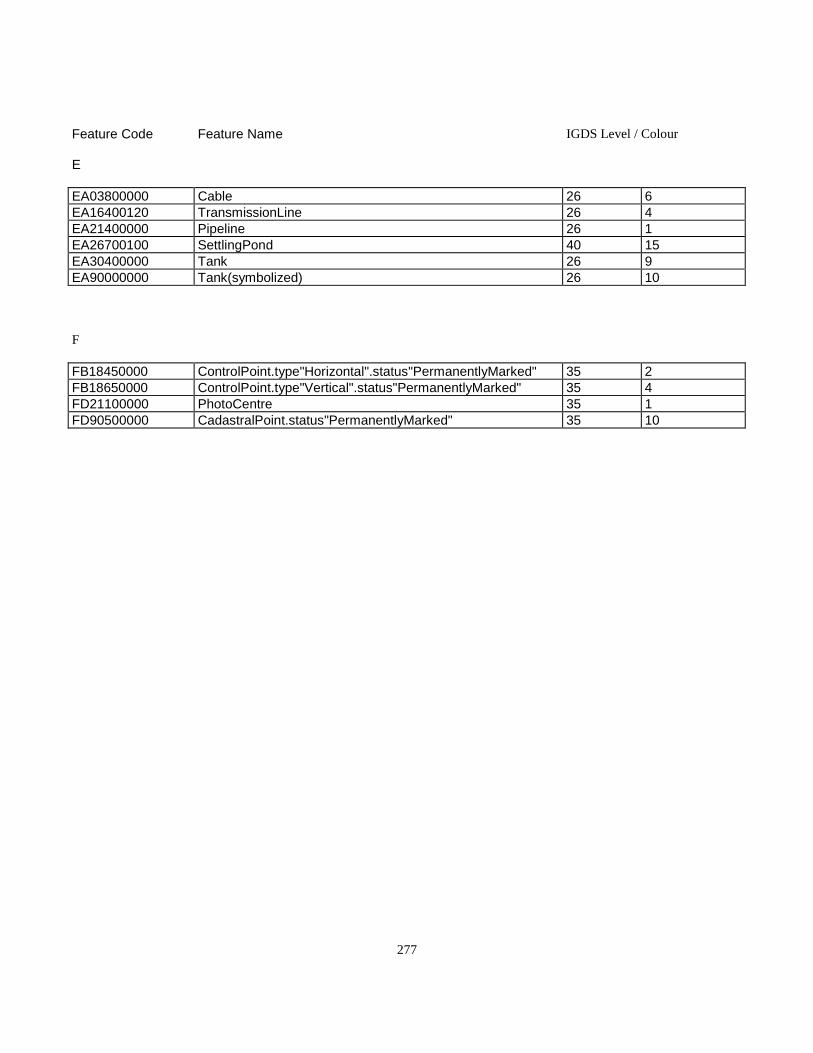
277
Feature Code Feature Name IGDS Level / Colour
E
EA03800000 Cable 26 6EA16400120 TransmissionLine 26 4EA21400000 Pipeline 26 1EA26700100 SettlingPond 40 15EA30400000 Tank 26 9EA90000000 Tank(symbolized) 26 10
F
FB18450000 ControlPoint.type"Horizontal".status"PermanentlyMarked" 35 2FB18650000 ControlPoint.type"Vertical".status"PermanentlyMarked" 35 4FD21100000 PhotoCentre 35 1FD90500000 CadastralPoint.status"PermanentlyMarked" 35 10
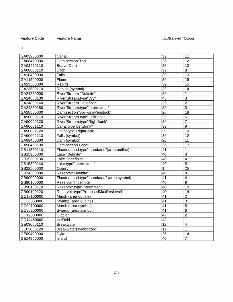
278
Feature Code Feature Name IGDS Level / Colour
G
GA03950000 Canal 39 11GA08450000 Dam.section"Top" 26 12GA08450110 BeaverDam 26 13GA08800110 Ditch 39 8GA10450000 Falls 39 13GA11500000 Flume 39 19GA23500000 Rapids 39 15GA23500110 Rapids (symbol) 39 14GA24850000 River/Stream "Definite" 39 1GA24850130 River/Stream.type"Dry" 43 3GA24850140 River/Stream "Indefinite" 39 2GA24850150 River/Stream.type"Intermittent" 39 3GA28550000 Dam.section"Spillway/Penstock" 26 18GA90000110 River/Stream.type"LeftBank" 39 6GA90000120 River/Stream.type"RightBank" 39 7GA90001110 Canal.type"LeftBank" 39 9GA90001120 Canal.type"RightBank" 39 10GA90002110 Falls (symbol) 39 12GA98450000 Dam (symbol) 26 11GA98450100 Dam.section"Base" 26 17GB11350110 FloodedLand.type"Inundated"(area outline) 41 1GB15300000 Lake "Definite" 40 3GB15300130 Lake "Indefinite" 40 4GB15300140 Lake.type"Intermittent" 40 5GB22500000 Quarry 1 25GB24300000 Reservoir"Definite" 40 8GB90000000 FloodedLand.type"Inundated" (area symbol) 41 4GB90100000 Reservoir"Indefinite" 40 9GB90100110 Reservoir.type"Intermittent" 40 10GB90100120 Reservoir.type"ProposedMaxResLevel" 40 14GC17100000 Marsh (area outline) 41 2GC30050000 Swamp (area outline) 41 3GC90100000 Marsh (area symbol) 41 5GC90200000 Swamp (area symbol) 41 6GD12300000 Glacier 42 2GD14450000 IceField 42 1GE03050110 Breakwater 12 4GE03050120 Breakwater(symbolized) 12 1GE09400000 Dyke 26 14GE14850000 Island 40 7

279
Feature Code Feature Name IGDS Level / Colour
G
GE25850000 Sand/GravelBar (area outline) 43 4GE26250000 SeaWall 12 16GE90100000 Sand/GravelBar (area symbol) 43 5GE90200000 FlowArrow 39 16GE90200110 Arrowhead 39 20GE94850000 Island (symbolized) 40 11GE94850100 Island "Position Approximate" 40 16GF28750000 Spring (symbol) 39 23GG05800000 Coastline"Definite" 43 1GG95800130 Coastline" Indefinite" 43 2
H
HA28700000 SpotHeight 49 1HA33100000 WaterLevel(DateofPhotography) 44 1HA90000000 Contour.type"Index" 47 1HA90000110 Contour.type"Index".option"Indefinite" 47 2HA90000130 Contour.type"Index".option"Depression" 47 3HA90000140 Contour.type"Index".option"DepressionIndefinite" 47 4HA90001000 Contour.type"Intermediate" 47 5HA90001110 Contour.type"Intermediate".option"Indefinite" 47 6HA90001130 Contour.type"Intermediate".option"Depression" 47 7HA90001140 Contour.type"Intermediate".option"DepressionIndefinite" 47 8HA90100000 DEMPoint.type"Definite" 51 1HA90100110 DEMPoint.type"Indefinite" 51 2HA90200000 BreakLine.type"Sharp" 51 5HA90200110 BreakLine.type"Round" 51 6HA90200120 BreakLine.type"Hypsographic" 51 15HA90200130 BreakLine.type"Hydrographic" 51 16HA90200140 BreakLine.type"TransportationandOtherManMade" 51 17HA90300000 DEMPoint.type"Interpolated" 51 3HA90400000 DEMPoint.type"Check" 51 11HB05650000 Cliff/Scarp 48 5HB07650130 VolcanicCrater 48 8HB10200000 Esker 48 3HB15850000 LavaBed 48 9HB18700000 Moraine 48 2HB18800000 MountainPeak 48 7HB26150000 Scree 48 4HB27550000 Sinkhole 39 21HB27900000 Slide (area outline) 48 1HB90000000 Slide (area symbol) 48 6HC90000000 AreaofExclusion 51 10HC90000100 AreaofIndefiniteContours 51 12
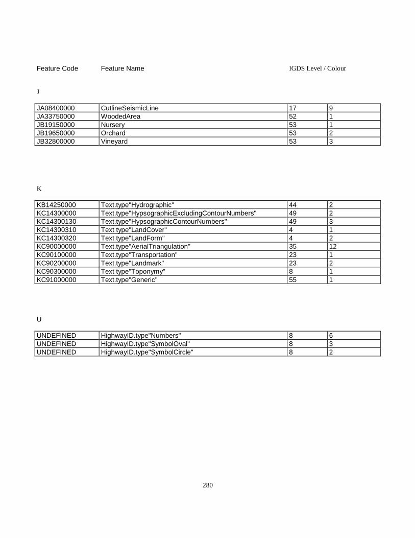
280
Feature Code Feature Name IGDS Level / Colour
J
JA08400000 CutlineSeismicLine 17 9JA33750000 WoodedArea 52 1JB19150000 Nursery 53 1JB19650000 Orchard 53 2JB32800000 Vineyard 53 3
K
KB14250000 Text.type"Hydrographic" 44 2KC14300000 Text.type"HypsographicExcludingContourNumbers" 49 2KC14300130 Text.type"HypsographicContourNumbers" 49 3KC14300310 Text type"LandCover" 4 1KC14300320 Text type"LandForm" 4 2KC90000000 Text.type"AerialTriangulation" 35 12KC90100000 Text.type"Transportation" 23 1KC90200000 Text.type"Landmark" 23 2KC90300000 Text type"Toponymy" 8 1KC91000000 Text.type"Generic" 55 1
U
UNDEFINED HighwayID.type"Numbers" 8 6UNDEFINED HighwayID.type"SymbolOval" 8 3UNDEFINED HighwayID.type"SymbolCircle" 8 2

281
F.2 Feature Name - Feature Code - Level/Colour Correlation
All digital data provided under this specification is uniquely identified by a feature object name that can be correlated to afeature code. Graphic display systems such as Intergraph do not allow for the inclusion of a unique alphanumeric code without theattachment of an external database. To provide feature uniqueness within such an environment, features have been assigned acombination of IGDS level (layer) and colour. This table lists the features by feature name and provides guidelines for levelplacement and colour assignment.
Feature Name Feature Code IGDS Level/ Colour
AAerialCableway CQ00300000 19 4AirField/Airstrip(Abandoned) AQ00550001 3 5AirField AQ00450000 3 2Airport AQ00500000 3 1Airstrip AQ00550000 3 3AmmunitionDump AJ00650000 1 2AreaofExclusion HC90000000 51 10AreaofIndefiniteContours HC90000100 51 12Arrowhead GE90200110 39 20AutoWrecker AB33850110 1 30
BBarn BA01450000 7 3Barn(symbolized) BA90000000 7 4Beacon(symbol) CQ01850000 12 9BeaverDam GA08450110 26 13BreakLine.type"Hydrographic" HA90200130 51 16BreakLine.type"Hypsographic" HA90200120 51 15BreakLine.type"Round" HA90200110 51 6BreakLine.type"Sharp" HA90200000 51 5BreakLine.type"TransportationandOtherManMade" HA90200140 51 17Breakwater GE03050110 12 4Breakwater(symbolized) GE03050120 12 1Bridge DD93250000 19 2Building BR90000000 7 2Building(symbol) BR90000110 7 1
BuiltupArea AR03400000 5 1Burner CG03550000 7 44

282
Feature Name Feature Code IGDS Level/ Colour
CCable.type"Insulated" EA03800000 26 6CadastralPoint.status"PermanentlyMarked"(symbol) FD90500000 35 10CampgroundCampsite AL03900000 1 3Canal.type"LeftBank" GA90001110 39 9Canal.type"RightBank" GA90001120 39 10Canal GA03950000 39 11Cemetery AM04560000 1 4Church BM05300000 7 29Church(symbolized) BM91100000 7 30CityHall(symbolized) BF91200000 7 32CityHall BF05550000 7 31CliffScarp HB05650000 48 5CoastlineGeometricRepQualifier:Definite GG05800000 43 1CoastlineGeometricRepQualifier:Indefinite GG95800130 43 2College BE05900000 7 23College(symbolized) BE90800000 7 24CommunicationsBuilding BC99250000 7 7CommunicationsBuilding(symbol) BC29250000 7 6Contour.type"Index" HA90000000 47 1Contour.type"Index".option"Depression" HA90000130 47 3Contour.type"Index".option"DepressionIndefinite" HA90000140 47 4Contour.type"Index".option"Indefinite" HA90000110 47 2Contour.type"Intermediate" HA90001000 47 5Contour.type"Intermediate".option"Depression" HA90001130 47 7Contour.type"Intermediate".option"DepressionIndefinite" HA90001140 47 8Contour.type"Intermediate".option"Indefinite" HA90001110 47 6ControlPoint.type"Horizontal".status"PermanentlyMarked"(symbol) FB18450000 35 2ControlPoint.type"Vertical".status"PermanentlyMarked"(symbol) FB18650000 35 4Conveyor CQ06400000 1 28Courthouse BF07550000 7 33Courthouse(symbolized) BF91300000 7 34Crane.type"Permanent" CG07610000 1 102CustomsOffice BF01850000 7 9CutEarthwork DD08350000 17 18CustomsOffice(symbolized) BF90100000 7 10CutlineSeismicLine JA08400000 17 9
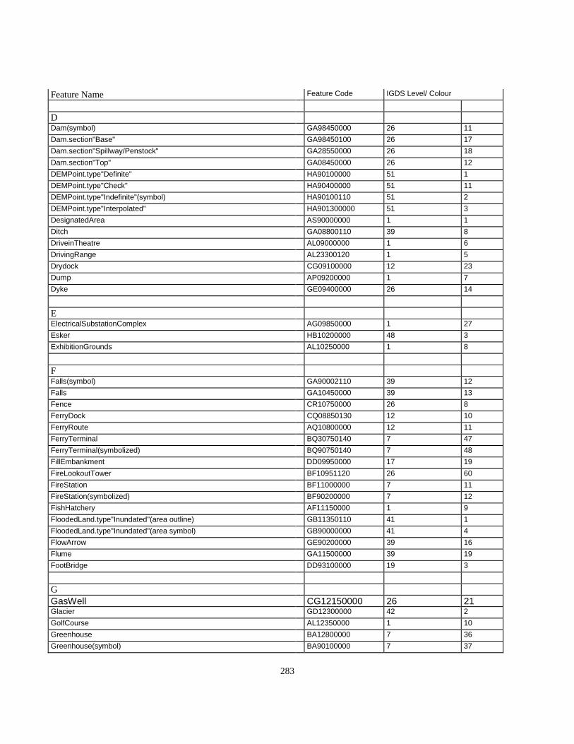
283
Feature Name Feature Code IGDS Level/ Colour
DDam(symbol) GA98450000 26 11Dam.section"Base" GA98450100 26 17Dam.section"Spillway/Penstock" GA28550000 26 18Dam.section"Top" GA08450000 26 12DEMPoint.type"Definite" HA90100000 51 1DEMPoint.type"Check" HA90400000 51 11DEMPoint.type"Indefinite"(symbol) HA90100110 51 2DEMPoint.type"Interpolated" HA901300000 51 3DesignatedArea AS90000000 1 1Ditch GA08800110 39 8DriveinTheatre AL09000000 1 6DrivingRange AL23300120 1 5Drydock CG09100000 12 23Dump AP09200000 1 7Dyke GE09400000 26 14
EElectricalSubstationComplex AG09850000 1 27Esker HB10200000 48 3ExhibitionGrounds AL10250000 1 8
FFalls(symbol) GA90002110 39 12Falls GA10450000 39 13Fence CR10750000 26 8FerryDock CQ08850130 12 10FerryRoute AQ10800000 12 11FerryTerminal BQ30750140 7 47FerryTerminal(symbolized) BQ90750140 7 48FillEmbankment DD09950000 17 19FireLookoutTower BF10951120 26 60FireStation BF11000000 7 11FireStation(symbolized) BF90200000 7 12FishHatchery AF11150000 1 9FloodedLand.type"Inundated"(area outline) GB11350110 41 1FloodedLand.type"Inundated"(area symbol) GB90000000 41 4FlowArrow GE90200000 39 16Flume GA11500000 39 19FootBridge DD93100000 19 3
GGasWell CG12150000 26 21Glacier GD12300000 42 2GolfCourse AL12350000 1 10Greenhouse BA12800000 7 36Greenhouse(symbol) BA90100000 7 37

284
Feature Name Feature Code IGDS Level/ Colour
HHelipad AQ13451000 3 12HighwayID.type"Numbers" UNDEFINED 8 6HighwayID.type"SymbolCircle" UNDEFINED 8 2HighwayID.type"SymbolOval" UNDEFINED 8 3Hospital BH13950000 7 13Hospital(symbolized) BH90300000 7 14
IIceField GD14450000 42 1Island GE14850000 40 7Island(symbolized) GE94850000 40 11Island "Position Approximate" GE94850100 40 16
L
Lake "Definite" GB15300000 40 3Lake "Indefinite" GB15300130 40 4Lake.type"Intermittent" GB15300140 40 5LavaBed HB15850000 48 9Library(symbolized) BE90700000 7 22Library BE16200000 7 21Lighthouse(symbolized) CQ16350000 12 8LumberYard AB33850140 1 31
MMarinaYaghtClub CQ08850160 12 15MarshInWater(area outline) GC17100110 41 9Marsh(area symbol) GC90100000 41 5MilitaryEstablishment AJ01650000 1 11Mine.type"OpenPit" AG17600000 1 22Mine AG17750000 1 12Moraine HB18700000 48 2MountainPeak HB18800000 48 7
NNursery JB19150000 53 1
OOilWell GC19600000 26 3Orchard JB19650000 53 2
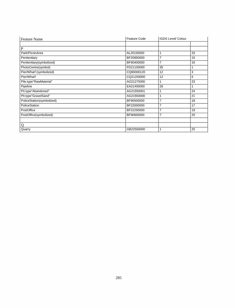
285
Feature Name Feature Code IGDS Level/ Colour
PPark/PicnicArea AL20150000 1 33Penitentiary BF20950000 7 15Penitentiary(symbolized) BF90400000 7 16PhotoCentre(symbol) FD21100000 35 1Pier/Wharf (symbolized) CQ90000120 12 3Pier/Wharf CQ21250000 12 6Pile.type"RawMaterial" AG21275000 1 23Pipeline EA21400000 26 1Pit.type"Abandoned" AG21550001 1 24Pit.type"GravelSand" AG21550000 1 21PoliceStation(symbolized) BF90500000 7 18PoliceStation BF22000000 7 17PostOffice BF22250000 7 19PostOffice(symbolized) BF90600000 7 20
QQuarry GB22500000 1 25
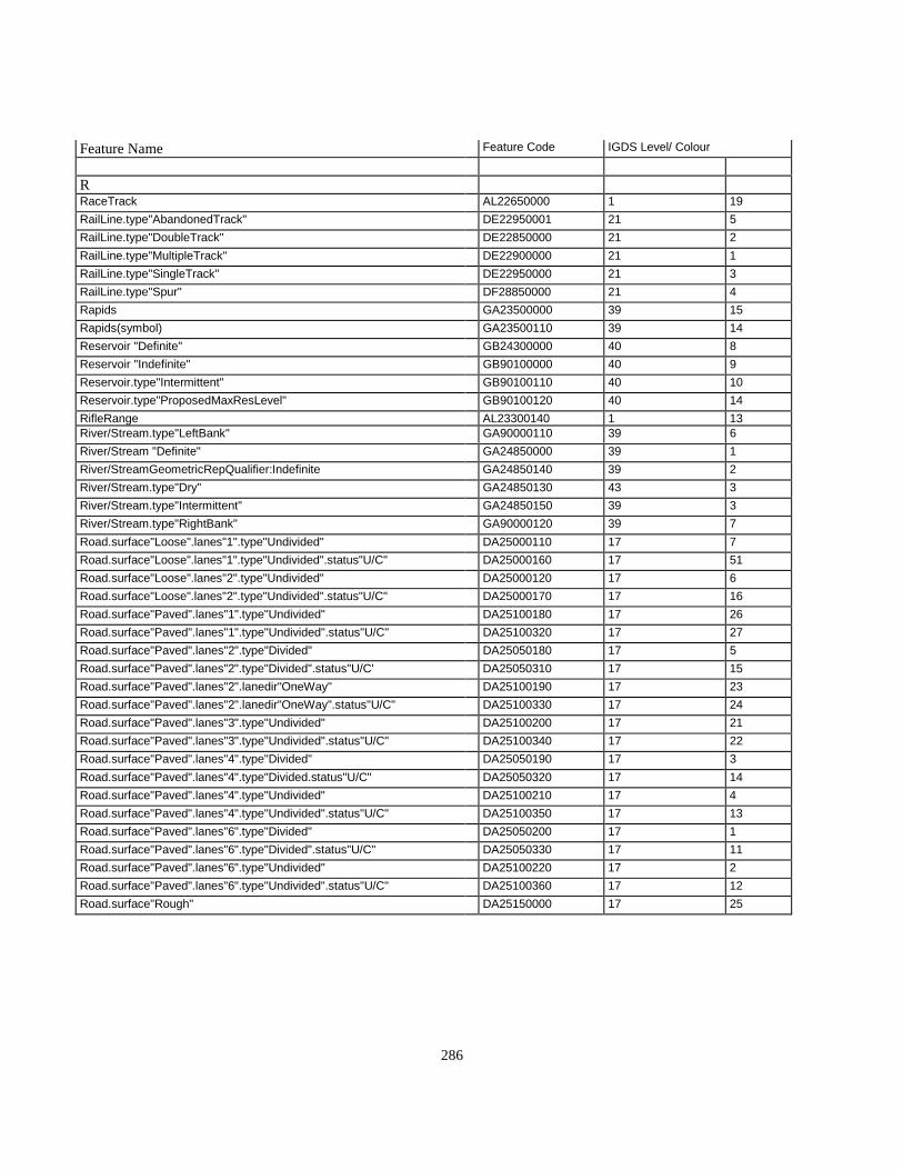
286
Feature Name Feature Code IGDS Level/ Colour
RRaceTrack AL22650000 1 19RailLine.type"AbandonedTrack" DE22950001 21 5RailLine.type"DoubleTrack" DE22850000 21 2RailLine.type"MultipleTrack" DE22900000 21 1RailLine.type"SingleTrack" DE22950000 21 3RailLine.type"Spur" DF28850000 21 4Rapids GA23500000 39 15Rapids(symbol) GA23500110 39 14Reservoir "Definite" GB24300000 40 8Reservoir "Indefinite" GB90100000 40 9Reservoir.type"Intermittent" GB90100110 40 10Reservoir.type"ProposedMaxResLevel" GB90100120 40 14RifleRange AL23300140 1 13River/Stream.type"LeftBank" GA90000110 39 6River/Stream "Definite" GA24850000 39 1River/StreamGeometricRepQualifier:Indefinite GA24850140 39 2River/Stream.type"Dry" GA24850130 43 3River/Stream.type"Intermittent" GA24850150 39 3River/Stream.type"RightBank" GA90000120 39 7Road.surface"Loose".lanes"1".type"Undivided" DA25000110 17 7Road.surface"Loose".lanes"1".type"Undivided".status"U/C" DA25000160 17 51Road.surface"Loose".lanes"2".type"Undivided" DA25000120 17 6Road.surface"Loose".lanes"2".type"Undivided".status"U/C" DA25000170 17 16Road.surface"Paved".lanes"1".type"Undivided" DA25100180 17 26Road.surface"Paved".lanes"1".type"Undivided".status"U/C" DA25100320 17 27Road.surface"Paved".lanes"2".type"Divided" DA25050180 17 5Road.surface"Paved".lanes"2".type"Divided".status"U/C' DA25050310 17 15Road.surface"Paved".lanes"2".lanedir"OneWay" DA25100190 17 23Road.surface"Paved".lanes"2".lanedir"OneWay".status"U/C" DA25100330 17 24Road.surface"Paved".lanes"3".type"Undivided" DA25100200 17 21Road.surface"Paved".lanes"3".type"Undivided".status"U/C" DA25100340 17 22Road.surface"Paved".lanes"4".type"Divided" DA25050190 17 3Road.surface"Paved".lanes"4".type"Divided.status"U/C" DA25050320 17 14Road.surface"Paved".lanes"4".type"Undivided" DA25100210 17 4Road.surface"Paved".lanes"4".type"Undivided".status"U/C" DA25100350 17 13Road.surface"Paved".lanes"6".type"Divided" DA25050200 17 1Road.surface"Paved".lanes"6".type"Divided".status"U/C" DA25050330 17 11Road.surface"Paved".lanes"6".type"Undivided" DA25100220 17 2Road.surface"Paved".lanes"6".type"Undivided".status"U/C" DA25100360 17 12Road.surface"Rough" DA25150000 17 25

287
Feature Name Feature Code IGDS Level/ Colour
SSand/GravelBar(area outline) GE25850000 43 4Sand/GravelBar(area symbol) GE90100000 43 5School BE26000000 7 25School(symbolized) BE90900000 7 26Scree HB26150000 48 4SeaWall GE26250000 12 16SettlingPond EA26700100 40 15SewageTreatmentArea AP26750000 1 14Silo(symbol) BA90000110 7 5Sinkhole HB27550000 39 21SkiJump CL27750000 7 45SkiLift CL27800000 26 7Slide(area outline) HB27900000 48Slide(area symbol) HB90000000 48 6SmokestackChimney CG28300000 7 43Snowshed DD28350000 20 6SportsField AL21900000 1 15SportTrack AL22650110 1 20SpotHeight(symbol) HA28700000 49 1Spring GF28750000 39 23StockYard AB33850150 1 32Swamp(area outline) GC30050000 41 3Swamp(area symbol) GC90200000 41 6

288
Feature Name Feature Code IGDS Level/ Colour
TTailingArea AP30300000 1 26TailingPond AP90300100 40 13Tank EA30400000 26 9Tank(symbol) EA90000000 26 10Text.type"AerialTriangulation" KC90000000 35 12Text.type"Cadastral" KC90400000 35 1Text.type"Generic" KC91000000 55 1Text.type"Hydrographic" KB14250000 44 3Text.type"HypsographicContourNumbers" KC14300130 49 3Text.type"HypsographicExcludingContourNumbers" KC14300000 49 2Text.type"LandCover" KC14300310 4 1Text.type"Landmark" KC90200000 23 2Text.type"Toponymy" KC90300000 8 1Text.type"Transportation" KC90100000 23 1TollGate DD31000000 7 46TollGate(symbol) DD91000000 7 52Tower.type"Microwave" CC31150110 26 19Tower.type"Unspecified" CC31150000 26 16Tower"Transmission" CC90000000 26 2Trail DD31700000 17 8TrailerPark AN31950000 1 17TransmissionLine EA16400120 26 4Trestle DD93200000 20 2Tunnel DD93220000 20 4Turntable DD3230000 21 8
U
University BE32400000 7 27University(symbolized) BE91000000 7 28
VVineyard JB32800000 53 3VolcanicCrater HB07650130 48 8
WWall.type"Retaining" DD24600000 17 20WaterLevel(DateofPhotography)(symbol) HA33100000 44 1WeighScale CG33250000 7 50WeighScale(symbolized) CG33250100 7 51WoodedArea JA33750000 52 1
YYard AB33850000 1 16
ZZoo AL33900000 1 18

289
F.3 - Level/Colour Correlation - Feature Name - Feature Code
All digital data provided under this specification is uniquely identified by a feature object name that can be correlated to afeature code. Graphic display systems such as Intergraph do not allow for the inclusion of a unique alphanumeric codewithout the attachment of an external database. To provide feature uniqueness within such an environment, features havebeen assigned a combination of IGDS level (layer) and colour. This table lists the features by IGDS level and colour for eachfeature name and code.
Level Colour Feature Name Feature Code
1 1 DesignatedArea AS900000001 2 AmmunitionDump AJ006500001 3 CampgroundCampsite AL039000001 4 Cemetery AM045600001 5 DrivingRange AL233001201 6 DriveinTheatre AL090000001 7 Dump AP092000001 8 ExhibitionGrounds AL102500001 9 FishHatchery AF111500001 10 GolfCourse AL123500001 11 MilitaryEstablishment AJ016500001 12 Mine AG177500001 13 RifleRange AL233001401 14 SewageTreatmentArea AP267500001 15 SportsField AL219000001 16 Yard AB338500001 17 TrailerPark AN319500001 18 Zoo AL339000001 19 RaceTrack AL226500001 20 SportTrack AL226501101 21 Pit.type"GravelSand" AG215500001 22 Mine.type"OpenPit" AG176000001 23 Pile.type"RawMaterial" AG212750001 24 Pit.type"Abandoned" AG215500011 25 Quarry GB225000001 26 TailingArea AP303000001 27 ElectricalSubstationComplex AG098500001 28 Conveyor CQ064000001 30 AutoWrecker AB338501101 31 LumberYard AB338501401 32 StockYard AB33850150
33 1 Airport AQ005000003 2 AirField AQ004500003 3 Airstrip AQ005500003 4 Helipad AQ134500003 5 Airport.status"Abandoned" AQ00550001
44 1 Text.type"LandCover" KC143003104 2 Text.type"LandForm" KC14300320

290
Level Colour Feature Name Feature Code
55 1 BuiltupArea AR03400000
77 1 Building(symbol) BR900001107 2 Building BR900000007 3 Barn BA014500007 4 Barn(symbol) BA900000007 5 Silo(symbol) BA900001107 6 CommunicationsBuilding(symbol) BC292500007 9 CustomsOffice BF018500007 11 FireStation BF110000007 12 FireStation(symbol) BF902000007 13 Hospital BH139500007 14 Hospital(symbol) BF903000007 15 Penitentiary BF209500007 16 Penitentiary(symbol) BF904000007 17 PoliceStation BF220000007 18 PoliceStation(symbol) BF905000007 19 PostOffice BF222500007 20 PostOffice(symbol) BF906000007 21 Library BE162000007 22 Library(symbol) BE907000007 23 College BE059000007 24 College(symbolized) BE908000007 25 School BE260000007 26 School(symbolized) BE909000007 27 University BE324000007 28 University(symbolized) BE910000007 29 Church BM035000007 30 Church(symbolized) BM911000007 31 CityHall BF055500007 32 CityHall(symbolized) BF912000007 33 Courthouse BF075500007 34 Courthouse(symbolized) BF913000007 36 Greenhouse BA128000007 37 Greenhouse(symbol) BA901000007 43 SmokestackChimney CG283000007 44 Burner CG035500007 45 SkiJump CL277500007 46 TollGate DD310000007 47 FerryTerminal BQ307501407 48 FerryTerminal(symbolized) BQ907501407 49 Crane.type"Permanent"(symbol) CG076000007 50 WeighScale CG332500007 51 WeighScale(symbolized) CG223501007 52 TollGate(symbol) DD91000000
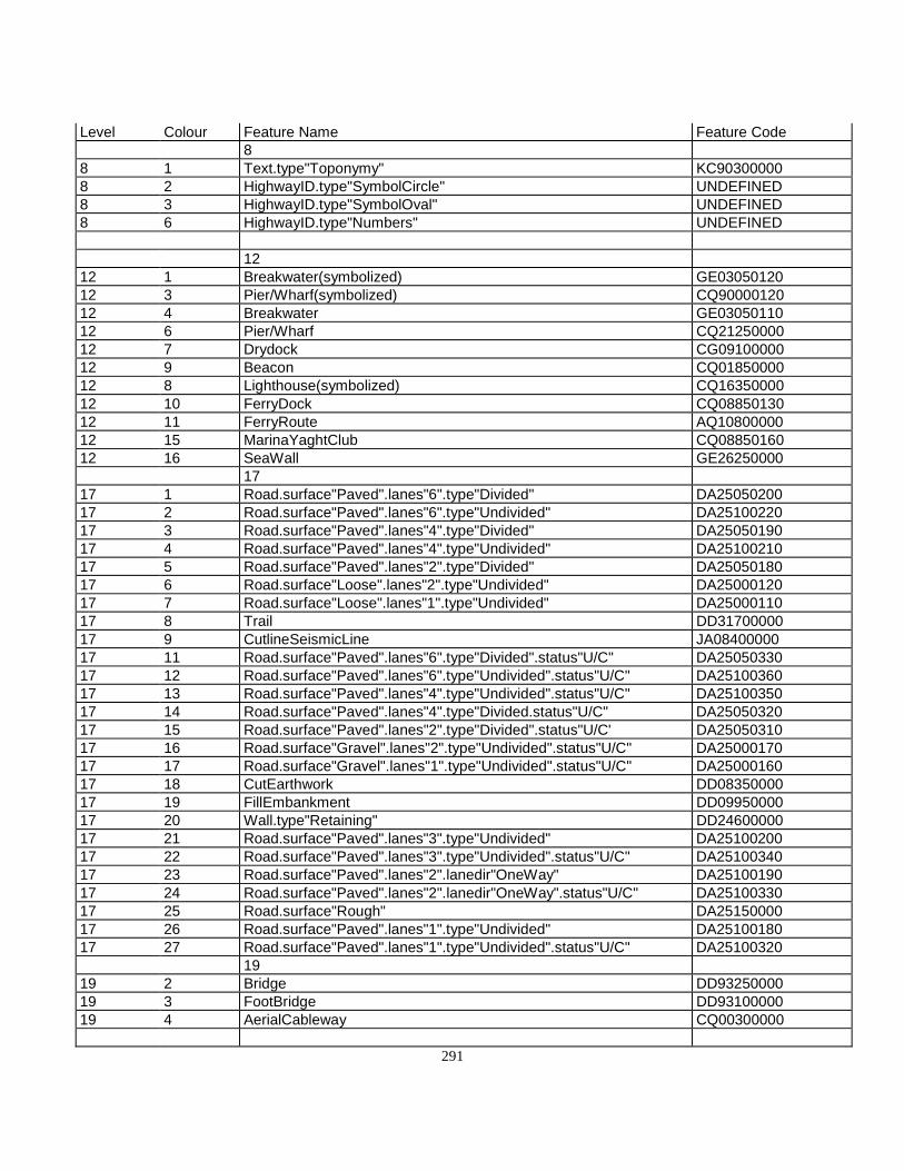
291
Level Colour Feature Name Feature Code8
8 1 Text.type"Toponymy" KC903000008 2 HighwayID.type"SymbolCircle" UNDEFINED8 3 HighwayID.type"SymbolOval" UNDEFINED8 6 HighwayID.type"Numbers" UNDEFINED
1212 1 Breakwater(symbolized) GE0305012012 3 Pier/Wharf(symbolized) CQ9000012012 4 Breakwater GE0305011012 6 Pier/Wharf CQ2125000012 7 Drydock CG0910000012 9 Beacon CQ0185000012 8 Lighthouse(symbolized) CQ1635000012 10 FerryDock CQ0885013012 11 FerryRoute AQ1080000012 15 MarinaYaghtClub CQ0885016012 16 SeaWall GE26250000
1717 1 Road.surface"Paved".lanes"6".type"Divided" DA2505020017 2 Road.surface"Paved".lanes"6".type"Undivided" DA2510022017 3 Road.surface"Paved".lanes"4".type"Divided" DA2505019017 4 Road.surface"Paved".lanes"4".type"Undivided" DA2510021017 5 Road.surface"Paved".lanes"2".type"Divided" DA2505018017 6 Road.surface"Loose".lanes"2".type"Undivided" DA2500012017 7 Road.surface"Loose".lanes"1".type"Undivided" DA2500011017 8 Trail DD3170000017 9 CutlineSeismicLine JA0840000017 11 Road.surface"Paved".lanes"6".type"Divided".status"U/C" DA2505033017 12 Road.surface"Paved".lanes"6".type"Undivided".status"U/C" DA2510036017 13 Road.surface"Paved".lanes"4".type"Undivided".status"U/C" DA2510035017 14 Road.surface"Paved".lanes"4".type"Divided.status"U/C" DA2505032017 15 Road.surface"Paved".lanes"2".type"Divided".status"U/C' DA2505031017 16 Road.surface"Gravel".lanes"2".type"Undivided".status"U/C" DA2500017017 17 Road.surface"Gravel".lanes"1".type"Undivided".status"U/C" DA2500016017 18 CutEarthwork DD0835000017 19 FillEmbankment DD0995000017 20 Wall.type"Retaining" DD2460000017 21 Road.surface"Paved".lanes"3".type"Undivided" DA2510020017 22 Road.surface"Paved".lanes"3".type"Undivided".status"U/C" DA2510034017 23 Road.surface"Paved".lanes"2".lanedir"OneWay" DA2510019017 24 Road.surface"Paved".lanes"2".lanedir"OneWay".status"U/C" DA2510033017 25 Road.surface"Rough" DA2515000017 26 Road.surface"Paved".lanes"1".type"Undivided" DA2510018017 27 Road.surface"Paved".lanes"1".type"Undivided".status"U/C" DA25100320
1919 2 Bridge DD9325000019 3 FootBridge DD9310000019 4 AerialCableway CQ00300000

292
Level Colour Feature Name Feature Code20
20 2 Trestle DD9320000020 4 Tunnel DD9322000020 6 Snowshed DD28350000
2121 1 RailLine.type"MultipleTrack" DE2290000021 2 RailLine.type"DoubleTrack" DE2285000021 3 RailLine.type"SingleTrack" DE2295000021 4 RailLine.type"Spur" DF2885000021 5 RailLine.type"AbandonedTrack" DE2295000121 8 RailwayTurntable DD3230000021 9 RailwayBumper(symbol) DD2565000021 11 RailwayScale(symbol) DD9165000021 12 RailLine.status"StreetCar".type"SingleTrack" DE2295016021 13 RailwaySwitch(symbol) DD30200000
2323 1 Text.type"Transportation" KC9010000023 2 Text.type"Landmark" KC90200000
2626 1 Pipeline EA2140000026 2 Tower.type"Transmission" CC9000000026 3 OilWell CG1960000026 4 TransmissionLine EA1640012026 6 Cable EA0380000026 7 SkiLift CL2780000026 8 Fence CR1075000026 9 Tank EA3040000026 10 Tank(symbol) EA9000000026 11 Dam(symbol) GA9845000026 12 Dam.section"Top" GA0845000026 13 BeaverDam GA0845011026 14 Dyke GE0940000026 16 Tower.type"Unspecified" CC3115000026 17 Dam.section"Base" GA9845010026 18 Dam.section"Spillway/Penstock" GA2855000026 19 Tower.type"Microwave" CC3115011026 20 FireLookoutTower BF1095012026 21 GasWell CG12150000
3535 1 PhotoCentre(symbol) FD2110000035 2 ControlPoint.type"Horizontal".status"PermanentlyMarked"(symbol) FB1845000035 4 ControlPoint.type"Vertical".status"PermanentlyMarked"(symbol) FB1865000035 10 CadastralPoint.status"PermanentlyMarked"(symbol) FD9050000035 12 Text.type"AerialTriangulation" KC90000000
3939 1 River/Stream"Definite" GA2485000039 2 River/Stream"Indefinite" GA2485014039 3 River/Stream.type"Intermittent" GA24850150

293
Level Colour Feature Name Feature Code39 6 River/Stream.type"LeftBank" GA9000011039 7 River/Stream.type"RightBank" GA9000012039 8 Ditch GA0880011039 9 Canal.type"LeftBank" GA9000111039 10 Canal.type"RightBank" GA9000112039 11 Canal GA0395000039 12 Falls(symbol) GA9000211039 13 Falls GA1045000039 14 Rapids(symbol) GA2350011039 15 Rapids GA2350000039 16 FlowArrow GE9020000039 19 Flume GA1150000039 20 Arrowhead(symbol) GE9020011039 21 Sinkhole HB2755000039 23 Spring GF28750000
4040 3 Lake"Definite" GB1530000040 4 Lake"Indefinite" GB1530013040 5 Lake.type"Intermittent" GB1530014040 7 Island GE1485000040 8 Reservoir"Definite" GB2430000040 9 Reservoir"Indefinite" GB9010000040 10 Reservoir.type"Intermittent" GB9010011040 11 Island(symbol) GE9485000040 13 TailingPond AP9030010040 14 Reservoir.type"ProposedMaxResLevel" GB9010012040 15 SettlingPond EA2670010040 16 Island"Position Approximate" GE94850100
4141 1 FloodedLand.type"Inundated"(area outline) GB1135011041 2 Marsh(area outline) GC1710000041 3 Swamp(area outline) GC3005000041 4 FloodedLand.type"Inundated"(area symbol) GB9000000041 5 Marsh(area symbol) GC9010000041 6 Swamp(area symbol) GC90200000
4242 1 IceField GD1445000042 2 Glacier GD12300000
4343 1 Coastline"Definite" GG0580000043 2 Coastline"Indefinite" GG9580013043 3 River/Stream.type"Dry" GA2485013043 4 Sand/GravelBar(area outline) GE2585000043 5 Sand/GravelBar(area symbol) GE90100000
4444 1 WaterLevel(DateofPhotography) HA3310000044 2 Text.type"Hydrographic" KB14250000
4747 1 Contour.type"Index" HA90000000

294
Level Colour Feature Name Feature Code47 2 Contour.type"Index".option"Indefinite" HA9000011047 3 Contour.type"Index".option"Depression" HA9000013047 4 Contour.type"Index".option"DepressionIndefinite" HA9000014047 5 Contour.type"Intermediate" HA9000100047 6 Contour.type"Intermediate".option"Indefinite" HA9000111047 7 Contour.type"Intermediate".option"Depression" HA9000113047 8 Contour.type"Intermediate".option"DepressionIndefinite" HA90001140
4848 1 Slide(area outline) HB2790000048 2 Moraine HB1870000048 3 Esker HB1020000048 4 Scree HB2615000048 5 CliffScarp HB0565000048 6 Slide(area symbol) HB9000000048 7 MountainPeak(symbol) HB1880000048 8 VolcanicCrater HB0765013048 9 LavaBed HB15850000
4949 1 SpotHeight HA2870000049 2 Text.type"HypsographicExcludingContourNumbers" KC1430000049 3 Text.type"HypsographicContourNumbers" KC14300130
5151 1 DEMPoint.type"Definite" HA9010000051 2 DEMPoint.type"Indefinite" HA9010011051 3 DEMPoint.type"Interpolated" HA9030000051 5 BreakLine.type"Sharp" HA9020000051 6 BreakLine.type"Round" HA9020011051 10 AreaofExclusion HC9000000051 11 DEMPoint.type"Check" HA9040000051 12 AreaofIndefiniteContours HC9000010051 15 BreakLine.type"Hypsographic" HA9020012051 16 BreakLine.type"Hydrographic" HA9020013051 17 BreakLine.type"TransportationandOtherManMade" HA90200140
5252 1 WoodedArea JA33750000
5353 1 Nursery JB1915000053 2 Orchard JB1965000053 3 Vineyard JB32800000
5555 1 Text.type"Generic" KC91000000

295

296
Appendix G Feature Name / Positional File Correlation

297
Appendix G - Feature Name / Positional File Correlation
Feature Pos - Planimetric Non - Positional DEM Raw ContourCode Code Code Code
AerialCableway CQ00300000 TextKC90100000
AQ00450000AirField TextKC90100000
AQ00550001 TextAirfield/Airstrip.status“Abandoned” KC90100000Airport AQ00500000Airstrip AQ0550000 Text
KC90100000AmmunitionDump AJ00650000 Text
KC90100000AreaofExclusion HC90000000AreaofIndefiniteContours HC90000100Arrowhead GE90200110AutoWrecker AB33850110 Text
KD90200000Barn BA01450000Barn (symbol) BA90000000Beacon CQ01850000BeaverDam GA08450110 Breakline
HA90200130BreakLine.type”Hydrographic” HA90200130BreakLine.type”Hypsographic” HA90200120BreakLine.type”Round” HA90200110BreakLine.type”Sharp” HA90200000BreakLine.type”TransportationandOtherMandMade”
HA90200140
Breakwater GE03050110Breakwater (symbol) GE03050120Bridge DD93250000Building (symbol) BR90000110Building (to scale) BR90000000BuiltupArea AR03400000Burner CG03550000 text
KC90200000Cable.type”Insulated” EA03800000 text
KC90200000CadastralPoint.status “PermantentlyMarked”
FD90500000
CampgroundCampsite AL03900000 textKC90200000
Canal GA03950000 text BreaklineHA90200130
Canal.type”LeftBank” GA90001110 BreaklineHA90200130
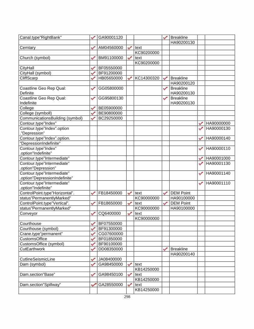
298
Canal.type”RightBank” GA90001120 BreaklineHA90200130
Cemtary AM04560000 textKC90200000
Church (symbol) BM91100000 textKC90200000
CityHall BF05550000CityHall (symbol) BF91200000CliffScarp HB05650000 KC14300320 Breakline
HA90200120Coastline Geo Rep Qual:Definite
GG05800000 BreaklineHA90200130
Coastline Geo Rep Qual:Indefinite
GG95800130 BreaklineHA90200130
College BE05900000College (symboll) BE90800000CommunicationsBuilding (symbol) BC29250000Contour.type”Index” HA90000000Contour.type”Index”.option.”Depression”
HA90000130
Contour.type”Index”.option. HA90000140“DepressionIndefinite”Contour.type”Index”.option”Indefinite”
HA90000110
Contour.type”Intermediate” HA90001000Contour.type”Intermediate”.option”Depression”
HA90001130
Contour.type”Intermediate”.option”DepressionIndefinite”
HA90001140
Contour.type”Intermediate”.option”Indefinite”
HA90001110
ControlPoint.type”Horizontal”. FB18450000 text DEM Pointstatus”PermanentlyMarked” KC90000000 HA90100000ControlPoint.type”Vertical”. FB18650000 text DEM Pointstatus”PermanentlyMarked” KC90000000 HA90100000Conveyor CQ6400000 text
KC90000000Courthouse BF07550000Courthouse (symbol) BF91300000Crane.type”permanent” CG07600000CustomsOffice BF01850000CustomsOffice (symbol) BF90100000CutEarthwork DD08350000 Breakline
HA90200140CutlineSeismicLine JA08400000Dam (symbol) GA98450000 text
KB14250000Dam.section”Base” GA98450100 text
KB14250000Dam.section”Spillway” GA28550000 text
KB14250000
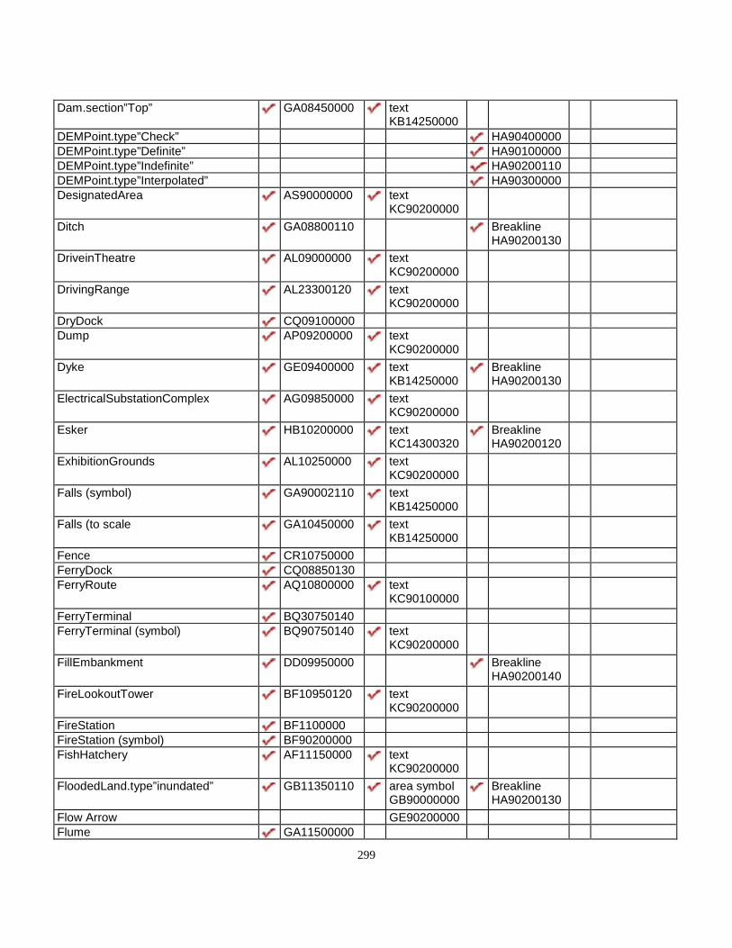
299
Dam.section”Top” GA08450000 textKB14250000
DEMPoint.type”Check” HA90400000DEMPoint.type”Definite” HA90100000DEMPoint.type”Indefinite” HA90200110DEMPoint.type”Interpolated” HA90300000DesignatedArea AS90000000 text
KC90200000Ditch GA08800110 Breakline
HA90200130DriveinTheatre AL09000000 text
KC90200000DrivingRange AL23300120 text
KC90200000DryDock CQ09100000Dump AP09200000 text
KC90200000Dyke GE09400000 text
KB14250000BreaklineHA90200130
ElectricalSubstationComplex AG09850000 textKC90200000
Esker HB10200000 textKC14300320
BreaklineHA90200120
ExhibitionGrounds AL10250000 textKC90200000
Falls (symbol) GA90002110 textKB14250000
Falls (to scale GA10450000 textKB14250000
Fence CR10750000FerryDock CQ08850130FerryRoute AQ10800000 text
KC90100000FerryTerminal BQ30750140FerryTerminal (symbol) BQ90750140 text
KC90200000FillEmbankment DD09950000 Breakline
HA90200140FireLookoutTower BF10950120 text
KC90200000FireStation BF1100000FireStation (symbol) BF90200000FishHatchery AF11150000 text
KC90200000FloodedLand.type”inundated” GB11350110 area symbol
GB90000000BreaklineHA90200130
Flow Arrow GE90200000Flume GA11500000

300
FootBridge DD93100000GaasWell CG12150000Glacier GD12300000 text
KB14250000Area of IndefContHC90000100
GolfCourse AL12350000 textKB14250000
Greenhouse (symbol) BA90100000Greenhouse (to sacle) BA12800000Helipad AQ13450000HighwayID.type”Numbers”HighwayID.type”SymbolCircle”HighwayID.type”SymbolOval”Hospital BH13950000 text
KC90200000Hoslital (symbol) BH90300000 text
KC90200000IceField GD14450000 text
KB14250000Area of IndefContHC90000100
Island Geo Rep Qual:Position Approximate
GE94850100 textKB14250000
Island GE14850000 BreaklineHA90200130
Island (symbol) GE94850000 BreaklineHA90100000
Lake Geo Rep Qual: Definite GB15300000 BreaklineHA90200130
Lake Geo Rep Qual: Indefinite GB15300130 BreaklineHA90200130
Lake type”Intermittent” GB15300140 BreaklineHA90200130
LavaBed HB15850000 textKC14300320
BreaklineHA90200120
Library BE16200000Library (symbol) BE90700000Lighthouse (symbol) CQ16350000LunberYard AB33850140 text
KC90200000Marina/Dock CQ08850160 text
KC90200000Marsh (area outline) GC17100000 area symbol
GC90100000BreaklineHA90200130
MilitaryEstablishment AL01650000 textKC90200000
Mine AG17750000 textKC90200000

301
Mine.type”OpenPit” AG17600000 textKC90200000
Area ofExclusionHC90000000
Moraine HB18700000 textKC90200000
BreaklineHA90200120
MountainPeak HB18800000 DEM PointHA90100000
Nursery JB19150000 textKC90200000
OilWell CG19600000Orchard JB19650000 text
KC90200000Park/PicnicArea AL20150000 text
KC90200000Penitentiary BF20950000 text
KC90200000Penitentiary (symbol) BF90400000PhotoCentre FD21100000 text
KC9000000Pier CQ21250000Pier (symbol) CQ90000120Pile AG21275000 text
KC9020000Area ofExclusionHC90000000
Pipeline EA21400000Pit.type”Abandoned” AG21550001 text
KC9020000BreaklineHA90200140
Pit.type”GravelSand” AG215560000 textKC9020000
Area ofExclusionHC90000000
PoliceStation BF22000000PloiceStation (symbol) BF90500000PostOffice BF22250000PostOffice (symbol) BF90600000Quarry.type”dry” AG22450000 text
KC9020000Area ofExclusionHC90000000
RaceTrack AL22650000 textKC9020000
RailLine.type”AbandonedTrack” DE22950001 BreaklineHA90200140
RailLine.type”DoubleTrack” DE22850000 textKC9010000
BreaklineHA90200140
RailLine.type”MultipleTrack” DE22900000 textKC9010000
BreaklineHA90200140
RailLine.type”SingleTrack” DE22950000 textKC9010000
BreaklineHA90200140

302
RailLine.type”Spur” DF28850000 BreaklineHA90200140
Rapids (symbol) GA23500110 textKB14250000
Rapids (to scale) GA23500000 textKB14250000
Reservoir Geo Rep Qual:Definite
GB24300000 textKB14250000
BreaklineHA90200130
Reservoir Geo Rep Qual:Indefinite
GB90100000 textKB14250000
BreaklineHA90200130
Reservoir.type”Intermittent” GB90100110 textKB14250000
BreaklineHA90200130
Reservoir.type“ProposedMaxResLevel”
GB90100120 textKB14250000
BreaklineHA90200130
RifleRange Al23300140 textKC90200000
River/Stream Geo Rep Qual:Definite
GA24850000 BreaklineHA90200130
River/Stream Geo Rep Qual:Indefinite
GA24850140 BreaklineHA90200130
River/Stream.type”Dry” GA24850130 BreaklineHA90200130
River/Stream.type”Intermittent” GA24850150 BreaklineHA90200130
River/Stream.type”LeftBank” GA90000110 BreaklineHA90200130
River/Stream.type”RightBank” GA90000120 BreaklineHA90200130
Road.surface”Gravel”.lanes”1Lane”
DA25000110 BreaklineHA90200140
Road.surface”Gravel”.lanes”1Lane” .status”U/C”
DA25000160 textKC90100000
BreaklineHA90200140
Road.surface”Gravel”.lanes”2Lane”
DA25000120 BreaklineHA90200140
Road.surface”Paved”.lanes”2Lane” .status”U/C”
DA25000170 textKC90100000
BreaklineHA90200140
Road.surface”Paved”.lanes”2Lane”
DA25050180 BreaklineHA90200140
Road.surface”Paved”.lanes”2Lanes”.lanedir”OneWay”
DA25100190 BreaklineHA90200140
Road.surface”Paved”.lanes”2Lanes”.lanedir”OneWay”.status”U/C”
DA25100330 textKC90100000
BreaklineHA90200140
Road.surface”Paved”.lanes”2Lanes”.lanedir.status”U/C”
DA25050310 textKC90100000
BreaklineHA90200140
Road.surface”Paved”.lanes”3Lanes” DA25100200 BreaklineHA90200140
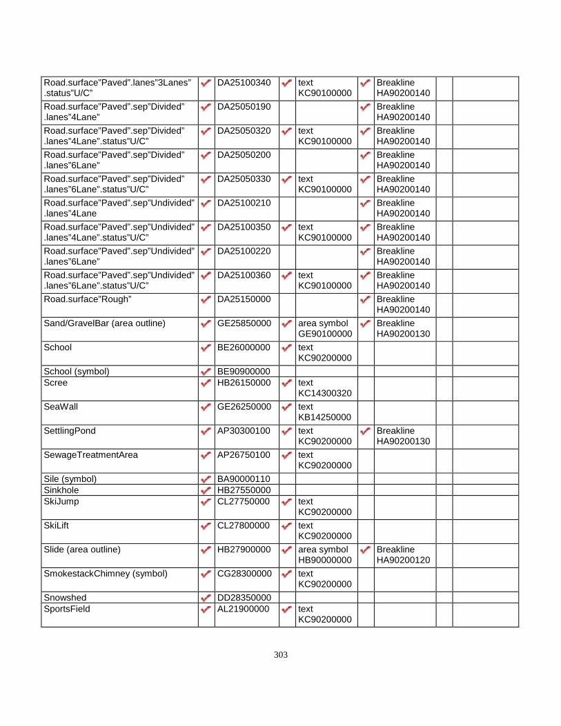
303
Road.surface”Paved”.lanes”3Lanes”.status”U/C”
DA25100340 textKC90100000
BreaklineHA90200140
Road.surface”Paved”.sep”Divided”.lanes”4Lane”
DA25050190 BreaklineHA90200140
Road.surface”Paved”.sep”Divided”.lanes”4Lane”.status”U/C”
DA25050320 textKC90100000
BreaklineHA90200140
Road.surface”Paved”.sep”Divided”.lanes”6Lane”
DA25050200 BreaklineHA90200140
Road.surface”Paved”.sep”Divided”.lanes”6Lane”.status”U/C”
DA25050330 textKC90100000
BreaklineHA90200140
Road.surface”Paved”.sep”Undivided”.lanes”4Lane
DA25100210 BreaklineHA90200140
Road.surface”Paved”.sep”Undivided”.lanes”4Lane”.status”U/C”
DA25100350 textKC90100000
BreaklineHA90200140
Road.surface”Paved”.sep”Undivided”.lanes”6Lane”
DA25100220 BreaklineHA90200140
Road.surface”Paved”.sep”Undivided”.lanes”6Lane”.status”U/C”
DA25100360 textKC90100000
BreaklineHA90200140
Road.surface”Rough” DA25150000 BreaklineHA90200140
Sand/GravelBar (area outline) GE25850000 area symbolGE90100000
BreaklineHA90200130
School BE26000000 textKC90200000
School (symbol) BE90900000Scree HB26150000 text
KC14300320SeaWall GE26250000 text
KB14250000SettlingPond AP30300100 text
KC90200000BreaklineHA90200130
SewageTreatmentArea AP26750100 textKC90200000
Sile (symbol) BA90000110Sinkhole HB27550000SkiJump CL27750000 text
KC90200000SkiLift CL27800000 text
KC90200000Slide (area outline) HB27900000 area symbol
HB90000000BreaklineHA90200120
SmokestackChimney (symbol) CG28300000 textKC90200000
Snowshed DD28350000SportsField AL21900000 text
KC90200000

304
SportTrack AL22650110 textKC90200000
SpotHeight textKC90300000
DEM PointHA90100000
SpringStockYard AB33850150 text
KC90200000Swamp (area outline) GC30030000 text
KC90200000BreaklineHA90200130
TailingArea AP30300000 textKC90200000
TailingPond AP90300100 BreaklineHA90200130
Tank (symbol) EA90000000Tank (to scale) EA30400000 text
KC90200000Text.type”AerialTriangulation” text
KC90000000Text.type”Hydrographic” text
KB14250000Text.type”HypsographicContourNumbers”Text.type”HypsographicExcludingContourNumbers”
textKC14300000
Text.type”LandCover” textKC14300310
Text.type”LandForm” textKC14300320
Text.type”LandMark” textKC90200000
Text.type”Toponymy” textKC90300000
Text.type”Transportation” textKC90100000
TollGate (symbol) DD91000000TollGate (to scale) DD31000000Tower.type”Microwave” CC31150110 text
KC90200000Tower.type”Transmission” CC90000000Tower.type”Unspecified” CC31150000Trail DD31700000 Breakline
HA90200140TrailerPark AN31950000 text
KC90200000TransmissionLine EA16400120Trestle DD93200000Tunnel DD93220000

305
Turntable DD32300000 textKC90100000
University BE32400000 textKC90200000
University (symbol) BE91000000Vineyard JB32800000 text
KC90200000VolcanicCrater HB079650130 text
KC14300320BreaklineHA90200120
Wall.type”Retaining” DD24600000 BreaklineHA90200140
WaterLevel(DateofPhotography) HA33100000 textKB14250000
WeighScale CG33250000WeighScale (symbol) CG33250100WoodedArea JA33750000Yard AB33900000 text
KC90200000Zoo AL33900000 text
KC90200000