brister et al. (45) date of patent: jul. 7, 2015 · 5,868,141 a 2, 1999 elias carvalho et al... an...
TRANSCRIPT

(12) United States Patent Brister et al.
US009072583B2
US 9,072,583 B2 Jul. 7, 2015
(10) Patent No.: (45) Date of Patent:
(54) INTRAGASTRIC VOLUME-OCCUPYING DEVICE AND METHOD FOR FABRICATING SAME
(75) Inventors: Mark C. Brister, Encinitas, CA (US); Kaushik A. Patel, Poway, CA (US); Andrew P. Rasdal, San Diego, CA (US); Nelson Quintana, San Diego, CA (US); Neil R. Drake, San Diego, CA (US); Antonio C. Llevares, Chula Vista, CA (US); Dubravka Markovic, San Diego, CA (US); Amy D. L. VandenBerg, San Diego, CA (US)
(73) Assignee: Obalon Therapeutics, Inc., Carlsbad, CA (US)
(*) Notice: Subject to any disclaimer, the term of this patent is extended or adjusted under 35 U.S.C. 154(b) by 562 days.
(21)
(22)
Appl. No.: 12/580,044
Filed: Oct. 15, 2009
(65) Prior Publication Data
US 2010/O1 OO116A1 Apr. 22, 2010
Related U.S. Application Data Provisional application No. 61/105,932, filed on Oct. 16, 2008.
(60)
Int. C. A6M 29/00 A6DF 5/00
(51) (2006.01) (2006.01)
(Continued) U.S. C. CPC ............... A6IF5/003 (2013.01); A61 F5/0073
(2013.01); A61 B 17/12099 (2013.01);
(52)
(Continued)
247 246 / /
(58) Field of Classification Search CPC. A01B 12/006; A61B 17/1204; A61B 19/54;
A61B 17/12099: A61M 25/1027; A61M 31/002; A61M 29/00; A61F 5/003: A61F
5/0073; A61F 5/0036 USPC ............. 606/1, 151,153, 192, 196, 197, 199;
128/898; 604/270, 506, 539,890.1; 206/522; 424/453; 446/186, 213, 224;
623/2.17, 2.18, 1.26 See application file for complete search history.
(56) References Cited
U.S. PATENT DOCUMENTS
1/1974 Michaels 3, 1974 Place
(Continued)
3,788,322 A 3,797.492. A
FOREIGN PATENT DOCUMENTS
10, 1986 3, 1984
(Continued) OTHER PUBLICATIONS
DE 354O936 C1 EP O103481
Al Kahtani et al., Bio-Enteric Intragastric Balloon in Obese Patients: A Retrospective Analysis of King Faisal Specialist Hospital Experi ence; Obes Surg; Aug 28, 2008.
(Continued)
Primary Examiner — Katherine Dowe Assistant Examiner — Amy R Weisberg (74) Attorney, Agent, or Firm — Knobbe Martens Olson & Bear, LLP (57) ABSTRACT
Intragastric Volume-occupying devices and methods for treat ing obesity are provided. The devices, which are inflated by carbon dioxide, include an aluminum or silicon oxide barrier layer providing carbon dioxide retention and an alkylene vinyl alcohol polymer layer providing structural integrity in V1VO.
19 Claims, 3 Drawing Sheets
A43 A4 g" 44/
g/

US 9,072,583 B2 Page 2
(51) Int. Cl. 2007, 0100208 A1 5/2007 Lewkowicz et al.
A6M 3L/00 (2006.01) 3:23:32: A 32 SER; 9 a. A61B 7/12 (2006.01) 2007. O156248 A1 7/2007 RE al. A61B 9/00 (2006.01) 2007/0207199 A1* 9/2007 Sogin ............................ 424/451 A61M 2.5/10 (2013.01) 2007/0212559 A1 9, 2007 Shah
(52) U.S. Cl. 2007/025O101 A1* 10, 2007 Hornet al. .................... 606, 192
CPC ....... A61B 17/1204 (2013,01); Y10T 156/1051 CES: A 23 Seal irk (2015.01); A61 B 19/54 (2013.01); A61 F5/0036 2008/0306506 A1* 12/2008 Leatherman .................. 606, 192
(2013.01); A61M 25/1027 (2013.01); A61M 2009,0182424 A1 7/2009 Marco et al. 31/002 (2013.01) 2009,0192535 A1 7/2009 Kasic, II et al.
2009/0259246 A1 10, 2009 Eskaros et al. 2010, 01001 17 A1* 4/2010 Brister et al. ................. 606, 192
(56) References Cited 2010.0137897 A1 6, 2010 Brister et al. 2011/0202127 A1* 8, 2011 Mauch et al. ................ 623.2.11
U.S. PATENT DOCUMENTS 2013,0165859 A1* 6, 2013 Imran ...... 604/101.01 2014/0221912 A1* 8, 2014 Imran ... ... 604,66
25. A E. it." et al. 2014/0221927 A1* 8, 2014 Imran et al. ................... 604f131
23:36 A to sung FOREIGN PATENT DOCUMENTS 4.416,267 A 11, 1983 Garren et al. 4,485,805. A 12/1984 Foster, Jr. EP O246.999 11, 1987 4,517,979 A 5, 1985 Pecenka WO WO 87,0.0034 1, 1987 4,560,392 A 12/1985 Basevi WO WO 87,0.0034 A2 1, 1987 4,607,618 A 8/1986 Angelchik WO WO99,25418 5, 1999 4,694,827 A 9, 1987 Weiner et al. WO WOO1? 68007 9, 2001 4,723,547 A 2f1988 Kullas et al. WO WO O2, 16001 2, 2002 4,739,758 A 4, 1988 Lai et al. WO WO O2/40O81 5, 2002 4,812,315 A 3, 1989 Tarabishi WO WO O2/091961 11, 2002 4,813,934. A 3/1989 Engelson et al. WO WOO3,055420 T 2003 4,857,029 A 8, 1989 Diericket al. WO WO 2004/084763 10, 2004 4,899,747 A 2f1990 Garren et al. WO WO 2006/020929 2, 2006 4,917,885 A 4, 1990 Chiba et al. WO WO 2007/136735 11, 2007 4,925,446 A 5/1990 Garay et al. WO WO 2009/055386 A2 4/2009 4929.214 A 5, 1990 Lieberman WO WO 2009/086119 A2 T 2009 5,049,106 A 9, 1991 Kimetal. WO WO 2010.045477 4/2010 5,084,061 A 1/1992 Gau et al. WO WO 2010/045482 4/2010 5,129,915 A 7, 1992 CantenvS et al. 5,234.454 A 8/1993 Bangs y OTHER PUBLICATIONS 5,259,399 A 11/1993 Brown 5,270,086 A * 12/1993 Hamlin ........................ 428, 35.2 Al-Momen et al., Intragastric Balloon for Obesity: A Retrospective 5,308,326 A 5, 1994 Zimmon Evaluation of Tolerance and Efficacy; Obes Surg: 2005:15(1): 101-5. 5.431,917 A 7, 1995 Yamamoto et al. Benjamin et al., Double-Blind Controlled Trial of the Garren sis h 3. A ck 38. SE 606/107 Edwards Gastric Bubble: An Adjunctive Treatment for Exogenous 5,852.889 A 12, 1998 R al. . . . . . . . . . . . . . . . . . . Obesity, Gastroenterology, vol. 95, No. 3, pp. 581-588, Sep. 1988. 5,868,141 A 2, 1999 Elias Carvalho et al... An Improved Intragastric Balloon Procedure Using a 5,897,205 A 4/1999 Sinsteden New Balloon: Preliminary Analysis of Safety and Efficacy, Obes 5,910,128 A 6/1999 Quinn Surg, 2008. 6.427,089 B1 7/2002 Knowlton Coskun et al., Bioenterics Intragastric Balloon: Clinical Outcomes of 6,454,785 B2 9/2002 De Hoyos Garza the First 100 Patients—ATurkish Experience, Obes Surg, Sep. 2008; 8.33 E. S. Real 18(9): 1154-6. published online Jun. 3, 2008. 6753512 B2 5, 2004 McGhan ....... o 606, 192 Dastis et al., Intragastric Balloon for Weight Loss: Results in 100 6,981,980 B2 * 1/2006 Sampson et al. .............. 606, 192 Individuals Followed for at Least 2.5 Years; Endoscopy. Jul. 2009; 6,988,983 B2 1/2006 Connors et al. 41(7):575-80; published online Jul. 8, 2009. 7,192,397 B2 3/2007 Lewkowicz et al. De Waele et al., Endoscopic Volume Adjustment of Intragastric Bal 7.682,306 B2 * 3/2010 Shah ............................. 600,116 loons for Intolerance, Obes Surg; Apr. 2001; 11(2):223-4. 7,699,863 B2 ck 39 Marco et al f Doldiet al., Treatment of Morbid Obesity With Intragastric Balloon 365, '3. E. s A. . . . . . . . . . . . . . . . . 606,196 in Association With Diet; Obes Surg: 2002; 12(4):583-7.
8,282,666 B2 10/2012 Birk .............................. 606, 192 Dumonceau, Evidence-Based Review of the Bioenterics Intragastric 8,562.589 B2 * 10/2013 Imran 604/890.1 Balloon for Weight Loss, Obes Surg. Dec. 2008;18(12):1611-7. pub 8,721,620 B2 * 5/2014 Imran ...... ... 604,503 lished online Jun. 21, 2008. 8,734,429 B2 * 5/2014 Imran etal 604/890.1 Durrans et al., Comparison of Weight Loss With Short Term Dietary 8,764,733 B2 * 7/2014 Imran ...... 604/890.1 and Intragastric Balloon Treatment; Gut 1989, 30, 565-568. 8,809,269 B2* 8/2014 Imran . 514/5.9 Eckhauser et al., Hydrostatic Balloon Dilation for Stomal Stenosis 8,809,271 B2 8, 2014 Imran ............................ 514/72 after Gastric Partitioning, Surgical Gastroenterology, vol. 3, No. 1,
2003/002 1822 A1 1/2003 Lloyd pp. 43-50, 1984. 3.84. A. 3. than Epia, Search Report dated Feb. 21, 2008 for EP App. No. 398-59 A. 23.9 Ra. . . . . . . . . . . . . . . . . 428, 35.7 European Search Report dated Jun. 22, 2010 for EP App. No. 2005/0222329 A1 10, 2005 Shah et al. 10004281.1 filed Mar. 17, 2004. 2005/0266109 A1* 12/2005 Chin et al. ................. 425,133.5 European Search Report dated Sep. 14, 2009 for EP App. No. 2005/0267405 A1 12, 2005 Shah 05786479 filed Aug. 15, 2005. 2006/0058829 A1* 3/2006 Sampson et al. .............. 606, 192 Evans et al., Intragastric Balloon in the Treatment of Patients With 2007/0078476 A1* 4, 2007 Hull et al. ..................... 606, 191 Morbid Obesity, British Journal of Surgery; 2001: 88: 1245-1248.

US 9,072,583 B2 Page 3
(56) References Cited
OTHER PUBLICATIONS
Fernandes et al., Intragastric Balloon for Obesity (Review); Cochrane Review; Jan. 24, 2007; Issue 1. Forestierietal. Heliosphere Bag in the Treatment of Severe Obesity: Preliminary Experience, Obes Surg; May 2006; 16(5):635-7. Gaggiotti et al., Adjustable Totally Implanted Intragastric Prosthesis (ATIIP). Endogast for Treatment of Morbid Obesity. One Year Fol low-Up of a Multicenter Prospective Clinical Survey; Obesity Sur gery. 2007: 17,949-956. Geliebter et al., Gastric balloon to treat obesity: a double-blind study in nondieting Subjects, The American Journal of Clinical Nutrition, vol. 51, pp. 584-588, 1990. Genco et al., Bioenterics Intragastric Balloon (BIB): A Short-Term, Double-Blind, Randomized, Controlled, Crossover Study on Weight Reduction in Morbidly Obese Patients; International Journal of Obe sity (Lond); Jan. 2006:30(1): 129-33; published online Sep. 27, 2005. Genco et al., Bioenterics Intragastric Balloon: The Italian Experience With 2,515 Patients; Obes Surg: 2005: 15(8): 1161-4. Genco et al., Intragastric Balloon or Diet Alone? A Retrospective Evaluation, Obes Surg, Aug. 2008; 18(8):989-92. published online May 16, 2008. Genco et al., Laparoscopic Sleeve Gastrectomy Versus Intragastric Balloon: A Case-Control Study, Surg Endosc. Springer Science & Business Media, published online Jan. 24, 2009. Gottig et al., Analysis of Safety and Efficacy of Intragastric Balloon in Extremely Obese Patients, Obes Surg, Jun. 2009; 19(6):677-83. published online Mar. 17, 2009. Imaz et al., Safety and Effectiveness of the Intragastric Balloon for Obesity. A Meta-Analysis; Obes Surg; Jul. 2008;18(7):841-6; pub lished online May 6, 2008. International Preliminary Report on Patentability dated Dec. 1, 2005 for PCT/US2004/008178 file Mar. 17, 2004. International Preliminary Reporton Patentability dated Jan. 13, 2009 for PCT/US2008/028850 filed Aug. 15, 2005. International Search Report and Written Opinion dated Oct. 15, 2004 for PCT/US2004/08178 filed Mar. 17, 2004. International Search Report dated Jul. 8, 2010 for PCT/US2009/ 060881 filed Oct. 15, 2009. International Search Report dated Jun. 25, 2008 for PCT/US2005/ 28850 filed Aug. 15, 2005. Langer, R., Drug delivery and targeting, Nature, Suuplement to vol. 392, No. 6679, pp. 5-10, Apr. 1998. Malik; Endoluminal and Transluminal Surgery: Current Status and Future Possibilities; Surgical Endoscopy;2006; 20(8): 1179-92. Martin et al., Safety of the Ullorex Oral Intragastric Balloon for the Treatment of Obesity, Journal of Diabetic Science and Technology, vol. 1, Issue 4, pp. 574-581, Jul. 2007. Mathus-Vliegen et al., Intragastric Ballon in the Treatment of Super morbid Obesity Double-Blind, Sham-Controlled, Crossover Evaluation of 500-Milliliter Balloon, Gastroenterology, vol. 99, No. 2, pp. 362-369, Aug. 1990.
Melissas et al., The Intragastric Balloon-Smoothing the Path to Bariatric Surgery, Obes Surg 2006; 16:897-902. Mion et al., Tolerance and Efficacy of an Air-Filled Balloon in Non Morbidly Obese Patients: Results of a Prospective Multicenter Study: Obes Surg; Jul. 2007; 17(7):764-769. Nieben et al., Ingtragastric Balloon as an Artificial BeZoar for Treat ment of Obesity, The Lancet, vol. 1, No. 8265, pp. 198-199, Jan. 1982. Ramhamadany et al. Effect of the Gastric Balloon Versus Sham Procedure on Weight Loss in Obese Subjects; Gut 1989; 30; 1054 1057. Rodriguez-Hermosa et al., Gastric Necrosis: A Possible Complica tion of the Use of the Intragastric Balloon in a Patient Previously Submitted to Nissen Fundoplication; Obes Surg; 19:1456-1459; pub lished online Jun. 9, 2009. Roman et al., Intragastric Balloon for “Non-Morbid” Obesity: A Retrospective Evaluation of Tolerance and Efficacy; Obes Surg; Apr. 2004; 14(4): 539-44. Sallet et al. Brazilian Multicenter Study of the Intragastric Balloon; Obesity Surgery; Aug. 2004; 14(7);991-998. Totte et al., Weight Reduction by Means of Intragastric Device: Experience With the Bioenterics Intragastric Balloon; Obes Surg; Aug. 2001; 11(4):519-23. Trande et al. Efficacy, Tolerance and Safety of New Intragastric Air-Filled Balloon (Heliosphere BAG) for Obesity: The Experience of 17 Cases; Obes Surg; Dec. 10, 2008. Vansonnenberg et al., Percutaneous Gastrostomy: Use of Intragastric Ballon Support, Radiology, vol. 152, No. 2, pp. 531-532, Aug. 1984. Wahlen et al., The Bioenterics Intragastric Balloon (BIB): How to Use It; Obes Surg: 2001; 11(4):524-7. International Search Report issued in corresponding PCT Applica tion No. PCT/US2009/060874, mailed May 26, 2010. DuPont Tie Resin Selector Simplifies Tie Layer Selection, “Newest Online Modeling Tool Simplifies Tie Layer Selection” Web Page at http://www2.dupont.com/Packaging Resins en US/whats new/ article20120618 tie resin tool.html–Jun. 18, 2012. DuPontTM Bynel(R) resins Web page at http://www2.dupont.com/ Bynellen US/ CopyrightC) 2012. LyondellBasell—Selecting a Tie-Layer Adhesive, Webpage at http:// www.lyondellbasell.com/Products/ByCategory/polymers/type? Polyethylene/SpecialtyPolyethylene TieLayerResins/Selecting a Tie layer Adhesive.htm—2012. LyondellBasell Tie-Layer Resins, Web page at http://www. lyondellbasell.com/Products/ByCategory/polymers/process/ TieLayerResins/ 2012. Mitsui Chemicals America, Inc., ADMERTM Adhesive Resin Web page at http://www.mitsuichemicals.com/adm.htm, CopyrightC) 1999-2012. Westlake Chemical, Polyethylene Division, Applications, Tie Layer Web page at http://www.westlake.com/fwil main Tie-Layer 170.html 2012.
* cited by examiner

US 9,072,583 B2 Sheet 1 of 3 Jul. 7, 2015 U.S. Patent
I "OIH

US 9,072,583 B2 Sheet 2 of 3 Jul. 7, 2015 U.S. Patent

U.S. Patent Jul. 7, 2015 Sheet 3 of 3 US 9,072,583 B2
s s & N \ NN
- - - - , , ) A N ------ a Y. . SNs ls 2 W s s

US 9,072,583 B2 1.
INTRAGASTRIC VOLUME-OCCUPYING DEVICE AND METHOD FOR FABRICATING
SAME
CROSS-REFERENCE TO RELATED APPLICATION
This application claims priority under 35 U.S.C. S 119(e) to U.S. Provisional Application No. 61/105,932, filed Oct. 16, 2008, the contents of which is hereby incorporated by refer ence herein in its entirety and is hereby made a portion of this specification.
FIELD OF THE INVENTION
Intragastric Volume-occupying devices and methods for treating obesity are provided. The devices, which are inflated by carbon dioxide, include an aluminum or silicon oxide barrier layer providing carbon dioxide retention and an alky lene vinyl alcohol polymer layer providing structural integ rity in vivo.
BACKGROUND OF THE INVENTION
Obesity is a major health problem in developed countries. Obesity is associated with a greater risk of developing high blood pressure, diabetes and many other serious health prob lems. In the United States, the complications of overweight and obesity are estimated to affect nearly one in three Ameri can adults. Except for rare pathological conditions, weight gain is directly correlated to overeating.
Noninvasive methods for reducing weight include increas ing metabolic activity to burn calories and/or reducing caloric intake, either by modifying behavior or with pharmacological intervention to reduce the desire to eat. Other methods include Surgery to reduce the stomach's Volume, banding to limit the size of the stoma, and intragastric devices that reduce the desire to eat by occupying space in the stomach.
Intragastric Volume-occupying devices provide the patient a feeling of Satiety after having eaten only small amounts of food. Thus, the caloric intake is diminished while the subject is satisfied with a feeling of fullness.
SUMMARY OF THE INVENTION
Currently available intragastric Volume-occupying devices have many shortcomings. These can include the necessity of complex and/or uncomfortable procedures to insert and/or remove the device; insufficient control of timing of inflation and/or deflation; insufficient control of the process of infla tion and/or deflation; and inability to maintain a proper level of inflation in vivo over a desired time period. The intragastric Volume-occupying devices of the preferred embodiments can overcome one of more of these shortcomings. Methods for manufacturing, deploying, inflating, tracking, deflating and retrieving of the intragastric Volume-occupying devices of the preferred embodiments are also provided, as are methods for treating obesity using the Volume-occupying devices of the preferred embodiments.
Invasive procedures for deploying and/or recovering the intragastric Volume-occupying devices of the preferred embodiments are not necessary; instead the devices are sim ply swallowed by a patient. Once in the stomach of the patient, the device increases in Volume. After a predetermined time period has passed, or upon demand, the device decreases in Volume and passes through the remainder of the patients digestive tract. Inflation is achieved through a chemical reac
10
15
25
30
35
40
45
50
55
60
65
2 tion between reactive agents producing an inflation gas, e.g., carbon dioxide. The intragastric Volume-occupying devices of the preferred embodiments comprise a composite film enclosing a space Susceptible to Volume expansion upon gen eration of the inflation gas. The composite film employed in the wall(s) of the intragastric Volume-occupying devices of the preferred embodiments include silicon oxides (SiOx: silica) or aluminum oxides (AlOX; alumina) as a carbon diox ide-retaining component. The composite film also includes alkylene vinyl alcohol polymers which provide improved structural integrity for the wall(s) of the intragastric Volume occupying devices.
In a first aspect, an intragastric balloon system is provided comprising a composite wall structure configured to maintain a CO, leak rate of less than or equal to 40 cc/m/day at 37°C., wherein the composite wall structure comprises: a Supporting film structure having a Young's Modulus of 500 Mpa or greater; a first CO barrier layer configured such that its CO barrier properties are not substantially affected by exposure to humidity levels within the gastric environment or within a central lumen of the balloon; and a second CO, barrier layer configured Such that its CO barrier properties are not Sub stantially affected by mechanical forces during processing, compacting, or application of external gastric pressures.
In an embodiment of the first aspect, the first CO barrier layer comprises a silicon dioxide layer having a thickness of from about 100 A to about 800 A.
In an embodiment of the first aspect, the second CO, bar rier layer comprises an ethylene vinyl alcohol layer having a thickness of at least about 2 microns.
In an embodiment of the first aspect, the first CO barrier layer comprises a silicon dioxide layer having a thickness of from about 100 A to about 800 A and the second CO, barrier layer comprises an ethylene vinyl alcohol layer having a thickness of at least about 2 microns.
In an embodiment of the first aspect, the Supporting film structure comprises a polyethylene terephthalate layer.
In an embodiment of the first aspect, the silicon dioxide layer is provided as a coating on one side of the polyethylene terephthalate layer.
In an embodiment of the first aspect, the ethylene vinyl alcohol layer is situated between two polyethylene layers, wherein the ethylene vinyl alcohol layer and the two polyeth ylene layers are bonded together with tie layers, and wherein the silicon dioxide layer is adhesively bonded to one of the polyethylene layers.
In an embodiment of the first aspect, the ethylene vinyl alcohol layer is extruded.
In an embodiment of the first aspect, the ethylene vinyl alcohol layer is co-extruded with one or more layers of poly ethylene.
In an embodiment of the first aspect, the ethylene vinyl alcohol layer is sandwiched between two polyethylenelayers.
In an embodiment of the first aspect, the intragastric bal loon system is configured to be Swallowable.
In an embodiment of the first aspect, the intragastric bal loon system is configured to be self-inflating.
In an embodiment of the first aspect, the intragastric bal loon system is configured to be swallowable and self-inflat 1ng.
In an embodiment of the first aspect, the intragastric bal loon system further comprises a self-sealing valve system attached to the composite wall of the balloon in a central lumen of the balloon by an adhesive with a shear force greater than about 40N, the self-sealing valve system comprising a septum, a retaining structure, and a continuous ring, wherein the septum has a durometer that is less thana durometer of the
US 9,072,583 B2 3
retaining structure, wherein the continuous ring is configured to exert a compressive force on the septum, wherein the balloon has a weight of less than about 15 g, wherein the balloon is configured to have a shape upon full inflation selected from the group consisting of ellipsoid, spheroid, and oblate spheroid, and wherein the balloon is configured to have a volume of from about 90 cm to about 350 cm upon full inflation.
In an embodiment of the first aspect, the intragastric bal loon system further comprises an inner container within the central lumen of the balloon, the inner container containing from about 0.28 grams to about 4 grams of an inflation agent, wherein up to about 80 wt.% of a total amount of the inflation agentis powdered citric acid, with a remainder of the inflation agent comprising powdered sodium bicarbonate.
In a second aspect, a method is provided for fabricating a composite wall for use in an intragastric balloon system, comprising: providing a polyethylene terephthalate layer coated with a silicon dioxide layer having a thickness of from about 100 A to about 800 A; providing a trilayer system comprising ethylene vinyl alcohol layer sandwiched between polyethylene layers; and adhesively bonding the silicon diox ide layer to one of the polyethylene layers, whereby a com posite wall structure configured to maintain a CO leak rate of less than or equal to 40 cc/m/day at 37° C. is obtained.
In an embodiment of the second aspect, a thickness of the composite wall structure is 2.5 mil or less.
In an embodiment of the second aspect, the ethylene vinyl alcohol layer is bonded to the polyethylene layers via tie layers.
In an embodiment of the second aspect, the method further comprises forming the composite wall into two components, each component having a same shape selected from the group consisting of elliptical, circular, and oval, wherein one of the components further comprises a hole having a Smallest dimension of at least about 0.6 cm, and a largest dimension of no more than about 3.8 cm; bonding the components together to form a wall of a balloon; inverting the wall of the balloon through the hole; and applying a patch of a material to seal the hole, whereby a balloon having a smooth outer Surface is obtained, wherein the balloon is configured to have a volume of from about 90 cm to about 350 cm upon full inflation.
In an embodiment of the second aspect, the method further comprises, before the step of bonding, adhering a self-sealing valve system to one of the components by an adhesive with a shear force greater than about 40 N, the self-sealing valve system comprising a septum, a retaining structure, and a continuous ring, wherein the septum has a durometer that is less than a durometer of the retaining structure, wherein the continuous ring is configured to exert a compressive force on the septum.
In an embodiment of the second aspect, the method further comprises, after the step of inverting and before the step of applying a patch, a step of placing an inner container within the inverted balloon, the inner container containing from about 0.28 grams to about 4 grams of an inflation agent, wherein up to about 80 wt.% of a total amount of the inflation agentis powdered citric acid, with a remainder of the inflation agent comprising powdered sodium bicarbonate, wherein the balloon has a weight of less than about 15 g.
BRIEF DESCRIPTION OF THE DRAWINGS
FIG. 1 is a diagram depicting the process of diffusion of e.g., a gas, through a film.
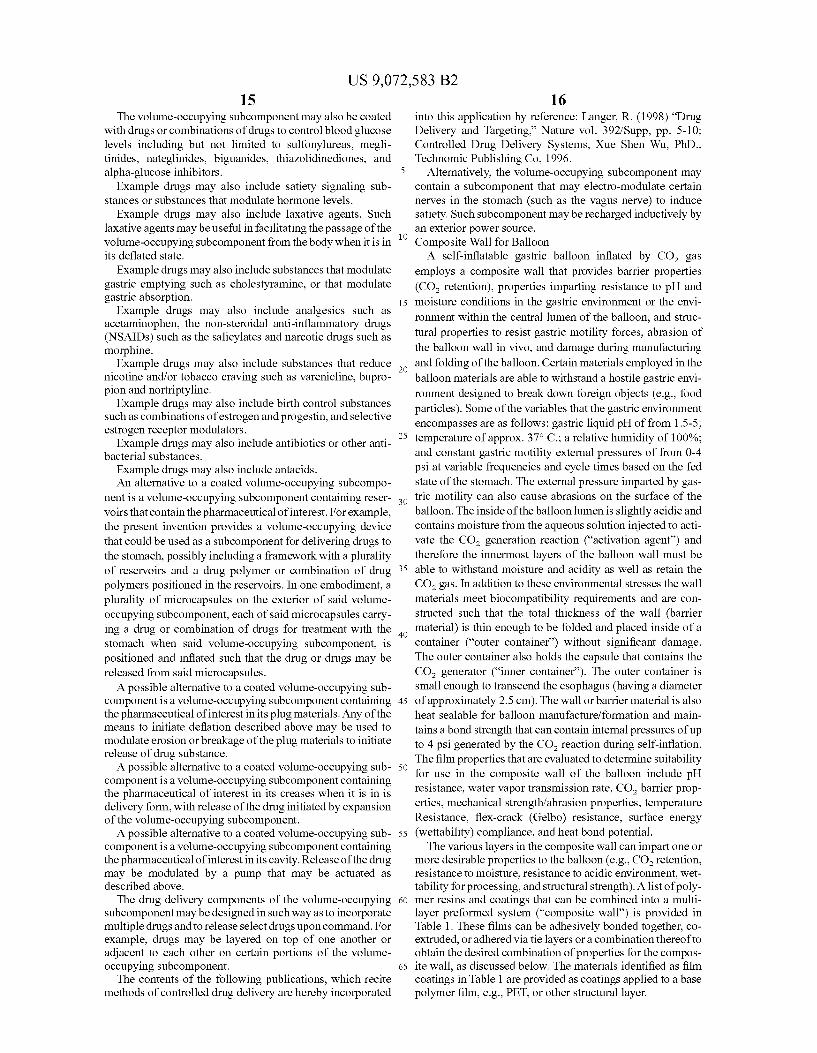
FIGS. 2A and 2B depict components of a swallowable, self-inflating intragastric balloon system. FIG. 2A depicts a
5
10
15
25
30
35
40
45
50
55
60
65
4 silicone head 441 with radioopacity ring 442, trimmed 30 D silicone septum 443, Nylon 6 inoculation spacer 444, folded balloon 445, inner container 446, and outer container 447 as constituents of the system in unassembled form. FIG. 2B depicts a fully assembled outer container 447 including vent hole 448 aligned with septum 449 for puncture to inject liquid activation agent.
DETAILED DESCRIPTION OF THE PREFERRED EMBODIMENT
The following description and examples illustrate a pre ferred embodiment of the present invention in detail. Those of skill in the art will recognize that there are numerous varia tions and modifications of this invention that are encom passed by its scope. Accordingly, the description of a pre ferred embodiment should not be deemed to limit the scope of the present invention. An orally ingestible intragastric Volume-occupying device
that is able to traverse the alimentary canal is provided. In certain preferred embodiments, a system including the
device can include a Volume-occupying Subcomponent, an inflation Subcomponent, a deflation Subcomponent, and a delivery Subcomponent. A tracking Subcomponent and/or a drug delivery Subcomponent can also optionally be employed. The term “degradable' as used herein is a broad term, and
is to be given its ordinary and customary meaning to a person of ordinary skill in the art (and is not to be limited to a special or customized meaning), and refers without limitation to a process by which structural integrity of the balloon is com promised (e.g., by chemical, mechanical, or other means (e.g., light, radiation, heat, etc.) Such that deflation occurs. The degradation process can include erosion, dissolution, separation, digestion, disintegration, delamination, commi nution, and other Such processes. The term 'swallowable' as used herein is abroad term, and
is to be given its ordinary and customary meaning to a person of ordinary skill in the art (and is not to be limited to a special or customized meaning), and refers without limitation to ingestion of a balloon by a patient such that the outer capsule and its constituents are delivered to the stomach via normal peristalsis movement. While the systems of preferred embodiments are swallowable, they are also configured by ingestion by methods other than Swallowing. The Swal lowability of the system is derived, at least in part, by the outer container size, which is sufficient to contain the inner con tainer and its constituents, an amount of activation agent injected prior to administration, the balloon size, and the balloon material thickness. The system is preferably of a size less than the average normal esophagus diameter. Inflation Subcomponents The intragastric Volume-occupying devices of preferred
embodiments are intended for ingestion by a patient and deployment without the need to resort to invasive methods. It is therefore desirable that the device be operable to conform to a compact delivery state which can be swallowed by a patient with minimal discomfort. Typically, in the delivery state, the device is in the form of an ingestible capsule or other similarly sized and shaped package. Once in the stomach, it is desirable for the device to assume a substantially larger deployed state. In order to achieve the transition from a deliv ery state to a deployed State the device is Subjected to an inflation step performed by an inflation Subcomponent. The inflation subcomponent is typically located within the
Volume-occupying Subcomponent or integrated into the wall of the Volume-occupying Subcomponent. The inflation Sub

US 9,072,583 B2 5
component can be self-contained, e.g., all elements necessary for inflation of the Volume-occupying Subcomponent are situ ated on or within the device at the time the patient ingests the device in the delivery state. Alternatively, in order to inflate, the inflation Subcomponent can employ outside inputs such as fluids, activation agents, or externally generated signals or other forms of communication.
Preferably, the inflation subcomponent includes a mixture of Solid sodium bicarbonate and Solid citric acid encased within a gelatin capsule. Inflation is initiated by injecting water, preferably as an aqueous solution of citric acid, into the capsule or other structure encapsulating the gelatin capsule inflation Subcomponent. An acidic aqueous solution is pre ferred to water or an aqueous solution at neutral or basic pH when a gelatin capsule inflation Subcomponent is employed. This is because dissolution of the gelatin capsule inflation Subcomponent is inhibited in acid solution, such that inflation is delayed for a suitable time period. The inflation time can also be slowed by increasing the wall thickness of the gelatin capsule; however, in order to minimize the total volume of the device, it is more desirable to employ a gelatin capsule with a thinner wall and to employ an acidic solution to delay infla tion time.
The relative amounts of sodium bicarbonate and citric acid are selected so as to consume all sodium bicarbonate while minimizing the amount of solid residue after reaction. Excess Sodium bicarbonate remaining in the inflated device is unde sirable in that, after deflation is initiated and the wall of the device is breached, the unreacted Sodium bicarbonate can result in undesirable re-inflation upon contact with acidic stomach contents. Accordingly, it is preferred to have citric acid present in a small excess. For example, the solid sodium bicarbonate and Solid citric acid can be present in the capsule in a stoichiometric amount, with the injected aqueous solu tion of citric acid providing the excess. Alternatively, excess citric acid can be present in dry form in the capsule. It is desirable to have only a minimal excess of citric acid, so as to minimize residue remaining after reaction and to minimize the size of the inflation subcomponent. Preferably, a slight excess of citric acid is employed; however, in certain embodi ments a larger excess of citric acid can be employed. The inflation subcomponent is preferably configured to
inflate while in the stomach (preferably, from about 2 minutes to about 30 minutes after injection of the device with an activating agent such as citric acid). The time to inflation is selected so as to the capsule Sufficient time to pass through the esophagus, but not to enter the pylorus or Small intestine before inflation occurs.
Instead of Sodium bicarbonate and citric acid, other gas generating chemical reactions can alternatively be employed, e.g., combining wax, O, and heat to form CO and H2O: combining NaHCO and acetic acid to form CO and H2O: combining Sugar and yeast to form ethanol and CO, com bining C, H, an XO, and energy to form XCO, and yHO: combining Sulfur and O. to form SO, combining potassium and water to form H and KOH, combining CHO and yeast to form 2CH-OH and 2CO, combining cupric bicar bonate and heat to form CuO, water and CO; combining magnesium and HSO to form H and MgSO, combining NaHCO and HCl to form water, CO, and NaCl; a combus tion reaction; or combining dry ice and heat to form CO.
In Such embodiments it may or may not be necessary to compartmentalize or otherwise separate the components of the chemical reaction while the device is in the delivery state. For example, solid sodium bicarbonate and solid citric acid can be combined to form an inflation Subcomponent mixture without the need for compartmentalization. Such a mixture is
10
15
25
30
35
40
45
50
55
60
65
6 then activated upon contact with water oran aqueous Solution of citric acid. When compartmentalization is employed, one skilled in the art will understand that various methods exist for temporarily separating the components, including but not limited to employing: temperature sensitive barriers, energy sensitive barriers, time sensitive barriers, light sensitive bar riers, other environmentally sensitive barriers, chemically sensitive barriers, and mechanical barriers.
For example, an inflation Subcomponent that includes a liquid and a solid reactant packaged into a two-part capsule can be employed. For example, the Solid reactant may be in the form of a carbonate such as bicarbonate. The liquid and Solid reactants are separated by a mechanical barrier present within the capsule. To initiate the chemical reaction between the liquid and the Solid reactant, a force is applied to the capsule causing the capsule to break and the liquid and solid reactant to mix and react with one another. The resulting reaction produces a gas byproduct which thereby inflates the Volume-occupying Subcomponent with which the inflation Subcomponent is associated.
It may be advantageous to delay the initiation of Such reaction until the device has had sufficient time to reach the stomach. Accordingly, another embodiment of the device may contain an additional soluble barrier positioned between the solid reactant and the mechanical barrier to be broken. Such additional barrier may be, for example, a dissolvable polysaccharide or gelatin barrier that dissolves within several minutes of contact with the liquid Such that inflation agents do not mix and the chemical reaction does not occur until several minutes following the breaking of the capsule. As a further example, the Volume-occupying Subcompo
nent may be formed of a shape-memory or thermo-elastic polymer designed to assume a Volume-occupying shape when in its natural, low energy state. Such a Volume-occupy ing Subcomponent may initially assume a restricted or con strained form, of a size and shape for ingestion by a patient while causing minimal discomfort, through packaging of the subcomponent into a dissolvable or biodegradable material or other container. Once the shape-memory Volume-occupying Subcomponent enters the stomach, the chemical or tempera ture environment of the stomach causes the restrictive ele ment to break or disintegrate, by dissolution, degradation or other means, allowing the Volume-occupying Subcomponent to expand to its natural state. Means for restricting Such shape-memory Volume-occupying Subcomponent include, but are not limited to, a polysaccharide capsule. Devices according to the present embodiment may, but need not nec essarily employ a cover or sheath. When employed. Such cover or sheath may function to create an internal cavity within the device that is isolated from the exterior environ ment and/or contents of the stomach. Thermo-elastic or memory shaped polymers for the above embodiments include latex, silicon, polyurethane, ethylene vinyl acetate (EVA) and ethylene vinyl alcohol (EVOH).
In certain embodiments, it may also be advantageous for the Volume-occupying Subcomponent to inflate gradually or in several steps over time. For example, if gas escapes the Volume-occupying Subcomponent prior to the desired defla tion time, it would be beneficial for the device to reinflate in order to preserve it in its expanded State. To this end, in certain additional embodiments of the present invention, the volume occupying Subcomponent may contain one or more inflation Subcomponents that cause the Volume-occupying Subcompo nent to inflate gradually or in steps over time. For example, the chemical components which react with one another to inflate with the Volume-occupying Subcomponent may be separated in several compartments such that they will react

US 9,072,583 B2 7
gradually or in steps over time. For example, Solid reactants and liquid may be separated by barriers designed to degrade at different times. As a further example, a first barrier may be designed to degrade several minutes following activation of the device while other barriers may be designed to degrade over the course of days, weeks or months. Such degradable barriers may be composed of any biodegradable or dissolv able material Such as polyacetals or polyketals, with the deg radation properties of the barrier determined by altering the composition thereof. The commencement of the barrier deg radation process may be initiated by any of the trigger mecha nisms described herein. Another way to achieve gradual infla tion would be for one of the gas generating reactants to be produced gradually by the degradation of a precursor over time (e.g. over hours, days, weeks or months). For example, a polymer Such as polylactic glycolic acid (PLGA) may be degraded over time to produce acid byproducts that react with another reactant contained in the Volume-occupying Subcom ponent to generate gas. The commencement of the precursor degradation process may be initiated by any of the trigger mechanisms described herein.
In other embodiments, it may be desirable that once the delivered device reaches the stomach, the Volume-occupying Subcomponent inflates quickly to a desired size in order to reduce the danger of the Volume-occupying Subcomponent passing through the pyloric sphincter following delivery. To achieve Such a rapid inflation, one of the inflation agents, e.g. bicarbonate, may be deployed in Such a manner Such as to maximize it Surface area. Accordingly, upon mixing of the inflation agents, a greater amount of gas may be generated at the beginning of the reaction, resulting in a more rapid expan sion of the volume-occupying subcomponent earlier follow ing delivery. Similarly, it may be advantageous for the infla tionary reactants to be engineered such that a reaction between small portions of the reactants occurs initially to help to catalyze a larger reaction between the remaining reactants. Such initial Smaller reaction may also be used to cause an initial expansion of the device to dislocate or move other components within the device into a state necessary or desir able for inflation or for the device's inflated state. For example, the reactants may be constructed Such that, upon initiation of the inflation step, citric acid first comes into contact with a small concentration of carbonate, triggering an initial reaction that helps to mix the remaining reactants to initiate a larger reaction. In one embodiment, the device is designed to provide for an initial Smaller inflationary reaction that helps to catalyze a Subsequent largerinflationary reaction and to initiate the movement of other components within the device to positions necessary or desirable for inflation or the devices inflated State. Alternatively, a reagent may be deployed so as to have an initially rapid rate of reaction and a Subsequently decreasing rate. Such a variable rate of reaction and thereby inflation of the Volume-occupying Subcompo nent may be achieved by deploying, for example, a solid reagent in the form of a compressed ball.
In another embodiment, the device may contain a wicking element in proximity to the gas generating reactants that, once in contact with a liquid reactant, serve as a medium for the liquid reactant to travel on in order to contact the solid reac tant to initiate the inflation reaction. Such an embodiment would be advantageous because it would facilitate the chemi cal reaction by facilitating contact between reactants, and it may also enable a more complete reaction by facilitating contact between a higher proportion of the reactants than could be accomplished in the absence of the wicking element. For example, the wicking element may be composed of a hydrophilic material, such as paper, that allows a liquid reac
10
15
25
30
35
40
45
50
55
60
65
8 tant to travel to a solid reactant by means of capillary action. In another embodiment, the wicking element may contain or be implanted with the solid reactant on all or a part of its Surface. Deflation Subcomponents
According to the preferred embodiments, deflation of the Volume-occupying Subcomponent is achieved without resort to invasive procedures. Deflation Subcomponents may func tion as a programmed time based deflation in which, after a certain period of time has lapsed since deployment ordelivery of the device, the device self-deflates, without external stimu lus. Alternatively, deflation may be externally triggered by a stimulus applied by the physician. Devices according to the preferred embodiments may employ a combination of the deflation Subcomponents to provide greater ease of operation and greater control and safety of the device.
In a preferred embodiment the Volume-occupying Subcom ponent may contain a biodegradable or dissolvable head that upon degradation allows fluid to escape and the Volume occupying Subcomponent to deflate. The head may be con structed in Such a manner that disintegration of the head materials from the Volume-occupying Subcomponent accel erates after a degree of degradation has occurred. For example, a first portion of the head may be designed to degrade faster than a second portion of head with the first portion stabilizing the second portion of the head Such that when the first portion degrades, second portion destabilize and is released from the head, thereby accelerating the defla tion process. Examples of head designs can include outer portions held together by a faster degrading centerpiece, a head with a slower degrading outer half and faster degrading inner half. An inner portion may also be partially held together by a water soluble adhesive that, upon degradation of the outer half of the head, becomes in contact with the con tents of the stomach, resulting in accelerated disintegration of the inner half of the head. The deflation subcomponent may contain more than one head through which fluid is released upon deflation.
In certain preferred embodiments, the degradable head may contain materials that are degraded by enzymes that are normally present in the stomach, such as pepsin or other proteases.
Alternatively, the head may incorporate a tension element, Such as a spring, a degradable link, and one or more plug elements. The degradable link serves to secure the tension element around plug element Such that, upon degradation of the degradable link, tension element releases all or part of plug element from the head, thereby allowing for the escape of fluid from the Volume-occupying Subcomponent.
In certain alternative embodiments of the present inven tion, the deflation Subcomponent utilizes a chemical-based technique. For example, after the device has been deployed for a specific time period within the patient, the patient will ingest a Substance designed to target and degrade the material from which the Volume-occupying Subcomponent is formed or a sealing element incorporated within the Volume-occupy ing Subcomponent. The degrading Substance may be ingested by the patient in the form of a pill, capsule, or liquid. Prefer ably, the degrading Substance is operable to cause deflation within a predictable, short period of time (e.g., less than 24 hours, preferably less than 12 hours, less than 6 hours, less than 3 hours, or less than 1 hour) following administration of the degrading Substance. For example, the all or part of the Volume-occupying Subcomponent wall or head may be com posed of a polymer that is degraded by one or more specific enzymes or bacteria, with the degrading Substance to be administered being the applicable enzyme or bacteria.

US 9,072,583 B2 9
It may be advantageous to design the device in ways that improve the rate of deflation of the Volume-occupying Sub component or cause it to deflate more completely. To this end, all or part of the Volume-occupying Subcomponent may incorporate an elastomeric material (silicon, for example) that forms a sheath or wall that applies a contracting force on the Volume-occupying Subcomponent and facilitates defla tion once the Volume-occupying Subcomponent has been breached. The contraction force applied by sheath or wall may be applied in an asymmetric manner to the Volume occupying Subcomponent. For example, as the contraction force may act primarily along alongitudinal axis such that the deflated Volume-occupying Subcomponent has a first dimen sion that is greater than a second dimension.
It may be advantageous for the Volume-occupying Sub component to contain a duct valve or other type of valve that allows fluid to exit the Volume-occupying Subcomponent upon initiation of the deflation step but that permits little or no fluid to enter or flow back into the subcomponent. Delivery Subcomponents
In the delivery state, devices according to the preferred embodiments employ a configuration that facilitates Swal lowing of the device while producing minimal discomfort to the patient. Preferably, the Volume-occupying Subcomponent is in a compressed configuration and other device Subcompo nents are sized so that the entire device may conform to the general shape of a capsule. In the delivery state, the device may be configured in any number of shapes, including the following: round, oblong, oval, Suppository-shaped, mush room-shaped, finger-shaped, bullet-shaped, or torpedo shaped. A bullet-shaped capsule, for example, may contain the contents of the Volume-occupying Subcomponent more efficiently.
In a preferred embodiment, the device is fitted into a stan dard sized gelatin capsule. The capsule may be formed of a material that has a know rate of degradation Such that the device will not be released from the capsule or otherwise deployed prior to entry into the stomach. For example, the capsule materials may include one or more polysaccharide and/or one or more polyhydric alcohols.
Alternatively, the device, in its delivery state, may be coated in a substance that confines the device in its delivery state while also facilitating Swallowing. The coating may be applied by a dipping, sputtering, vapor deposition, or spray ing process which may be conducted at an ambient or positive pressure.
In certain preferred embodiments, the encapsulated or coated device is lubricated or otherwise treated so as to facili tate Swallowing. For example, the encapsulated or coated device may be wetted, heated, or cooled, prior to Swallowing by the patient. Alternatively, the encapsulated or coated device may be dipped in a viscous substance that will serve to lubricate the device's passage through the esophagus. Examples of possible coatings would be any Substances with lubricious and/or hydrophilic properties and include glycer ine, polyvinylpyrrolidone (PVP), petroleum jelly, aloe Vera, silicon-based materials (e.g. Dow 360) and tetrafluoroethyl ene (TFE). The coating may also be applied by a sputtering, vapor deposition or spraying process.
In additional embodiments the coating or capsule is impregnated or treated with one or more local anesthetics or analgesics to ease Swallowing. Such anesthetics may include anesthetics in the amino amide group. Such as articaine, lidocaine and trimecaine, and anesthetics in the amino ester group, Such as benzocaine, procaine and tetracaine. Such analgesics may include chloraseptic.
10
15
25
30
35
40
45
50
55
60
65
10 In certain embodiments, the capsule may be weighted at a
certain end in order for it to be oriented appropriately when it is administered, as it travels down the esophagus, and/or when it is in the stomach. The weighting components may include polymer materials or inflation reactants.
It may advantageous for an administrator of the device to use a delivery tool for delivering the device to the mouth or facilitating its passage through the esophagus in the optimal orientation. A delivery tool may enable the device adminis trator to inject the device with one or more inflation agents as the device is being administered to the patient. In a preferred embodiment, such injection may be accomplished in the same mechanical action(s) of the administrator that are employed to release the device from the delivery tool into the mouth or esophagus. For example, the delivery tool may include a plunger, a reservoir having a liquid, and an injection needle. The administrator pushes the plunger which, either in sequence or approximately simultaneously, forces the injec tion needle into the device and thereby injects the liquid contained in reservoir into the device. Subsequent application of force to the plunger pushes the device out of the delivery tool and into the desired location within the patient. Further more, the delivery tool may also include a Subcomponent that administers an anesthetic or lubricant into the patient's mouth or esophagus to ease the swallowability of the device. Volume Occupying Subcomponent The Volume-occupying Subcomponent of the present
invention is generally formed of a flexible material forming a wall which defines an exterior surface and an interior cavity. Various of the above-described subcomponents may be either incorporated into the wall or interior cavity of the volume occupying subcomponent. The volume-occupying subcom ponent will vary in size and shape according to the patients internal dimensions and the desired outcome. The Volume occupying Subcomponent may be engineered to be semi compliant, allowing the Volume-occupying Subcomponent to stretch or expand with increases in pressure and/or tempera ture.
It is advantageous for the Volume-occupying Subcompo nent wall to be both high in strength and thin, with excellent CO retention properties. Accordingly, the Volume-occupy ing Subcomponent wall materials may be manufactured with a biaxial orientation that imparts a high modulus value to the Volume-occupying Subcomponent.
In one embodiment, a device according to the preferred embodiments can employ additional films or layers compris ing of a polymeric Substance such as polyurethane, polyeth ylene terephthalate, polyethylene naphthalene, polyvinyl chloride (PVC), Nylon 6, Nylon 12, or polyether block amide (PEBA). The volume-occupying subcomponent may be coated with one or more additional layers of Substances that aid in achieving greater gas-barrier characteristics. Such as a thermoplastic Substance.
Additional gas-barrier layers can also be employed in the device which have a low permeability to carbon dioxide or other fluids or gases. The barrier layers preferably exhibit good adherence to the base material. Such barrier coating materials include biocompatible poly(hydroxyamino ethers), polyethylene naphthalate, polyvinylidene chloride (PVDC), Saran, polyvinyl acetate, acrylonitrile copolymers or copoly mers of terephthalic acid and isophthalic acid with ethylene glycol and at least one diol. Alternative gas-barrier materials may include polyamine-polyepoxides. These materials are commonly acquired as a solvent or aqueous based thermoset ting composition and are generally spray-coated onto a pre form and then heat-cured to form the finished barrier coating. Alternative gas-barrier materials which may be applied as

US 9,072,583 B2 11
coatings to the Volume-occupying Subcomponent include metals such as silver or aluminum. Other materials that may be used to improve the gas impermeability of the volume occupying Subcomponent include, but are not limited to, gold or any noble metal, and PET coated with saran.
In certain preferred embodiments, the Volume-occupying Subcomponent includes films that are injection, blow or rota tional molded. Either immediately following Such molding, or after a period of curing, the gas-barrier coating may be applied.
In another embodiment, the intragastric Volume-occupy ing Subcomponent is formed using a Mylar polyester film with a coating comprising silver, aluminum or kelvalite as a metallicized Surface, to improve the gas impermeability of the Volume-occupying Subcomponent.
In the event that the Volume-occupying Subcomponents wall is composed of multiple layers of materials, it may be desirable to use certain Substances or methods to connect, attach or hold together Such multiple layers. Such substances can include a solvent or an ether-based adhesive. Such mul tiple layers may also be heat-bonded together. Once Such layers are attached together to form (for example) a sheet of material to be made into a Volume-occupying Subcomponent, it may also be necessary to apply additional treatment steps to Such material to allow it to seal together (for example, by application of a certain degree of heat and pressure) in order to be made into a Volume-occupying Subcomponent. Accord ingly, it may be advantageous to include as an additional layer in the Volume-occupying Subcomponent certain materials that seal. For example, a Volume-occupying Subcomponent which imparts favorable mechanical and gas impermeability characteristics to the volume-occupying subcomponent may be sealed by including a layer of sealing material in Such Volume-occupying Subcomponent.
According to another embodiment, the functionality of the Volume-occupying Subcomponent and the deflation compo nent is combined either in part or in whole. For example, the Volume-occupying Subcomponent may be formed of a Sub stance that is degraded within the stomach over a desired period of time. Once the degradation process has formed a breach in the wall of the Volume-occupying Subcomponent, the Volume-occupying Subcomponent deflates, continues to degrade and passes through the remainder of the digestive tract.
Preferably, an automated process is employed that takes a fully constructed Volume-occupying Subcomponent, evacu ates all of the air within the interior cavity and folds or compresses the Volume-occupying Subcomponent into the desired delivery state. For example, the evacuation of air from the Volume-occupying Subcomponent may be actuated by vacuum or mechanical pressure (e.g. rolling the Volume-oc cupying Subcomponent). In certain embodiments, it is desir able to minimize the number of creases produced in the vol ume-occupying Subcomponent when in the delivery state.
In another embodiment, deflation of the volume-occupy ing Subcomponent may be achieved through one or more injection site within the wall of the Volume-occupying Sub component may be used. For example, two self-sealing injec tion sites can be incorporated at opposite sides of the Volume occupying Subcomponent. The Volume-occupying Subcomponent may be positioned within a fixture that employs two small-gauge needles to evacuate the air from the Volume-occupying Subcomponent.
In one embodiment, the self-sealing injection sites may further be used to insert chemical elements of the inflation Subcomponent into the interior of the Volume-occupying Sub component. After injection of the chemical elements into the
10
15
25
30
35
40
45
50
55
60
65
12 Volume-occupying Subcomponent, the same needles may be used to perform evacuation of the Volume-occupying Sub component.
It may be desirable that the Volume-occupying Subcompo nent is packed into the delivery state under, for example, a negative vacuum pressure or under a positive external pres SUC.
The Volume-occupying Subcomponent wall materials may also be engineered to, once they are initially punctured or torn, tear relatively easily from the point of such puncture or tear. Such properties would, for example, be advantageous if deflation of the Volume-occupying Subcomponent were initi ated by a tearing or puncturing of the Volume-occupying Subcomponent wall, since Such initial tear or puncture may then increase in scope, hastening and/or maximizing the deflation process. The Volume-occupying Subcomponent may also be coated
by a lubricious Substance that facilitates its passage out of the body following its deflation. Examples of possible coatings would be any substances with lubricious and/or hydrophilic properties and include glycerine, polyvinylpyrrolidone (PVP), petroleum jelly, aloe Vera, silicon-based materials (e.g., Dow Corning R360 Medical Fluid; polydimethylsilox ane) and tetrafluoroethylene (TFE). The coating may be applied by a dipping, sputtering, vapor deposition or spraying process which may be conducted at an ambient or positive pressure. Tracking and Visualization Subcomponent
It may also be beneficial to implement tracking and visu alization functionality into devices according to the preferred embodiments. Due to the non-invasive nature of the present device, physicians may desire to determine, or confirm, the location and orientation of the device prior to inflation or during the course of treatment.
In one embodiment, the Volume-occupying Subcomponent incorporates a barium Sulfate or other radioopaque marker, e.g., a metal component Such as a metal ring. The marker may be implemented so as to form an identifiable geometric pat tern on the inflated Volume-occupying Subcomponent when imaged or otherwise viewed on X-ray or other visualization equipment. For example, the marker may form a circular stripe at the equator and/or a stripe around each pole of the Volume-occupying Subcomponent. When the markers form expanded circles and are positioned relatively far apart, this indicates that the Volume-occupying Subcomponent is in the deployed or inflated state. When the markers form condensed circles positioned relatively close together, this indicates that the Volume-occupying Subcomponent is in a deflated State. The distance between the markers indicates the degree to which the Volume-occupying Subcomponent is inflated.
Alternatively, the marker may be applied to the volume occupying Subcomponent when the Volume-occupying Sub component is in a creased or folded State Such that when the Volume-occupying Subcomponent is in its deflated State the marker appears concentrated when viewed on visualization equipment, and when the Volume-occupying Subcomponent is inflated the marker appears less concentrated when viewed on visualization equipment. Alternatively, the marker may be applied or incorporated into the Volume-occupying Subcom ponent so as to facilitate identification and location of the various Subcomponents of the device, such as a valve, head, or weight. The marker may be printed or painted onto a surface of the Volume-occupying Subcomponent or between layers of the material forming the Volume-occupying Subcomponent. Alternatively, a metal coating as described below may be used as a marker to identify and/or locate the Volume-occupying Subcomponent. Metal coatings for visualizing the Volume

US 9,072,583 B2 13
occupying Subcomponent may include silver, gold, tantalum or any noble metal. Alternatively, the marker may be applied to an elastomeric sleeve that covers all or part of the volume occupying Subcomponent.
In another embodiment, the Volume-occupying Subcompo nent incorporates a Subcomponent that changes mechanically upon inflation of the Volume-occupying Subcomponent, which mechanical change can be visualized using X-ray or other visualization equipment. For example, a mechanical portion of the Volume-occupying Subcomponent containing a visualization marker may elongate upon an increase in pres Sure in the Volume-occupying Subcomponent.
Alternatively, a marker may be formed using a metalized mesh located between layers of the material from which the Volume-occupying Subcomponent is constructed. The pattern or patterns formed by the imbedded marker will appear when the Volume-occupying Subcomponent is in an inflated, deployed State.
It is envisioned that marker materials may be incorporated into the Volume-occupying Subcomponent to facilitate vari ous visualization techniques such as, for example, MRI, CT and ultrasound. The Volume-occupying Subcomponent may also contain a
dye or marker that is released upon deflation to indicate that the Volume-occupying Subcomponent cavity has been breached. Such dye or marker may, for example, be apparent in the patient’s urine as an indication that the Volume-occu pying Subcomponent has begun to deflate.
In yet further embodiments, mechanical, chemical, visual and other sensors may be included as part of the device to measure, record and/or transmit information relating to the device and/or the patients internal environment. For example, the device may contain a camera or any of the other imaging and transmission components of a Pillcam device. As an additional example, the device may contain sensors that measure, record and/or transmit information relating to stom ach pH, stomach pressure, hormone levels, organ health, and organ safety. Drug Delivery Component
It is also envisioned that the device of the present invention may further achieve the objective of delivering and adminis tering various pharmaceutical therapies and treatments. Phar maceutical Substances may be incorporated into the material forming the Volume-occupying Subcomponent, into degrad able pockets formed on the interior or exterior surfaces of the Volume-occupying Subcomponent, and/or coated on the out side of the Volume-occupying Subcomponent. Alternatively or additionally, pharmaceutical Substances may be incorpo rated into or on one or more of the various other Subcompo nents of the device.
Different drugs may be applied in different regions on the Surface of the Volume-occupying Subcomponent. Alterna tively, the outside of the Volume-occupying Subcomponent may be comprised of a microporous or meshed exterior designed to facilitate deposition and release of drug materials. A Volume-occupying Subcomponent containing a mesh or microsphere like Surface where drugs may be deposited or embedded can be employed.
In certain embodiments, the Volume-occupying Subcom ponent may contain pharmaceutical Substances in an interior cavity which can be Subsequently released. The Volume-oc cupying Subcomponent can contain a drug in a Sub-compart ment of the Volume-occupying Subcomponent that is adjacent to the head. Release of the drug from Sub-compartment may beachieved by any number of means Such as by a pump, Valve or head breakage.
10
15
25
30
35
40
45
50
55
60
65
14 Alternatively, inflation Subcomponent may be configured
to gradually release pharmaceutical Substances as the head component(s) disintegrate or in bulk when the head compo nent separates from the Volume-occupying Subcomponent. For example, a pharmaceutical may be fixed in biodegradable plug materials and released as such materials degrade in the stomach. Such substances may be incorporated or implanted into a polymer (e.g. by means of diffusion or hydrolysis) which can be sprayed, sputter coated, vapor deposited or applied in liquid form onto the outside of the Volume-occu pying Subcomponent.
Furthermore, pharmaceutical Substances may also be incorporated into one or more of the barrier coatings of the Volume-occupying Subcomponent or a lubricious coating applied to the Volume-occupying Subcomponent. Release of the drug may, for example, be modulated by diffusion of the drug from the coating or by degradation of the coating itself. resulting in the release of the drug. The release or diffusion properties of the drug may be influenced by modifying the characteristics of the polymer, Such as by changing the ratio of hydrophobic to hydrophilic molecules in the composition of the polymer. Release of drug may also be modulated by electrophoresis actuated by remotely by an external Source.
It may be advantageous to treat the Volume-occupying Subcomponent such that its outer layer has antimicrobial properties so that it may treat or prevent stomach infections. For example, certain portions of the outer layer of the volume occupying Subcomponent may contain silver. As a further example, the outer layer of the Volume-occupying Subcom ponent may be made of a material (Such as polyurethane) that allows for ion transfer across of it, with silver materials behind such layer such that the silver ions are able to diffuse out of the Volume-occupying Subcomponent or onto its exte rior Surface.
For example, the Volume-occupying Subcomponent may be coated with a drug, or combination of drugs, to control stomach acid and other gastrointestinal conditions such as ulcers and gastroesophageal reflux disease (GERD). The drugs may, but need not be selected from the group of drugs including proton pump inhibitors such as PriloSec (omepra zole). Nexium (esomeprazole), Prevacid (lansoprazole), Pro tonix (pantoprazole) and Aciphex (rabeprazole) or H recep tor antagonists such as Tagamet (cimetidine), Pepcid (famotidine), AXid (nizatidine), Zantac (ranitidine) and Rotane (roXatadine). The Volume-occupying Subcomponent may be treated with
anti-emetics drug or combinations of anti-emetics to control nausea and Vomiting including, but not limited to. 5HT3 antagonists such as compazine, dolasetron, granisetron, ondansetron, tropisetron, palonosetron or dopamine antago nists such as domperidone, droperidol, haloperidol, chlorpro mazine, promethazine, prochlorperazine, metoclopramide, alizapride orantihistamines (H1 receptor antagonists) such as cyclizine, diphenhydramine, dimenhydrinate, meclizine, promethazine, hydroxy Zine or cannabinoids. The Volume-occupying Subcomponent may be coated with
drugs or combinations of drugs to control body weight including serotonin re-uptake inhibitors (e.g., fluoxetine), noradrenergic re-uptake inhibitors (e.g., phentermine), a serotonin and noradrenergic re-uptake inhibitor (Sibutra mine) and an intestinallipase inhibitor (orlistat), Leptin, amy lin, melanocortin-4 receptoragonists, neuropeptide Yantago nists, beta(3) adrenergicagonists and glucagon-like peptide-1 agonists and CB1 endocannabinoid receptor antagonists and CNS modulators that mediate appetite and energy expendi ture.
US 9,072,583 B2 15
The Volume-occupying Subcomponent may also be coated with drugs or combinations of drugs to control blood glucose levels including but not limited to Sulfonylureas, megli tinides, nateglinides, biguanides, thiazolidinediones, and alpha-glucose inhibitors.
Example drugs may also include Satiety signaling Sub stances or Substances that modulate hormone levels.
Example drugs may also include laxative agents. Such laxative agents may be useful in facilitating the passage of the Volume-occupying Subcomponent from the body when it is in its deflated state.
Example drugs may also include Substances that modulate gastric emptying Such as cholestyramine, or that modulate gastric absorption.
Example drugs may also include analgesics such as acetaminophen, the non-steroidal anti-inflammatory drugs (NSAIDs) such as the salicylates and narcotic drugs such as morphine.
Example drugs may also include Substances that reduce nicotine and/or tobacco craving Such as Varenicline, bupro pion and nortriptyline.
Example drugs may also include birth control Substances Such as combinations of estrogen and progestin, and selective estrogen receptor modulators.
Example drugs may also include antibiotics or other anti bacterial Substances.
Example drugs may also include antacids. An alternative to a coated Volume-occupying Subcompo
nent is a Volume-occupying Subcomponent containing reser Voirs that contain the pharmaceutical of interest. For example, the present invention provides a volume-occupying device that could be used as a Subcomponent for delivering drugs to the stomach, possibly including a framework with a plurality of reservoirs and a drug polymer or combination of drug polymers positioned in the reservoirs. In one embodiment, a plurality of microcapsules on the exterior of said Volume occupying Subcomponent, each of said microcapsules carry ing a drug or combination of drugs for treatment with the stomach when said Volume-occupying Subcomponent, is positioned and inflated Such that the drug or drugs may be released from said microcapsules. A possible alternative to a coated Volume-occupying Sub
component is a Volume-occupying Subcomponent containing the pharmaceutical of interest in its plug materials. Any of the means to initiate deflation described above may be used to modulate erosion or breakage of the plug materials to initiate release of drug Substance. A possible alternative to a coated Volume-occupying Sub
component is a Volume-occupying Subcomponent containing the pharmaceutical of interest in its creases when it is in is delivery form, with release of the drug initiated by expansion of the Volume-occupying Subcomponent. A possible alternative to a coated Volume-occupying Sub
component is a Volume-occupying Subcomponent containing the pharmaceutical of interestin its cavity. Release of the drug may be modulated by a pump that may be actuated as described above. The drug delivery components of the Volume-occupying
Subcomponent may be designed in Such way as to incorporate multiple drugs and to release select drugs upon command. For example, drugs may be layered on top of one another or adjacent to each other on certain portions of the Volume occupying Subcomponent. The contents of the following publications, which recite
methods of controlled drug delivery are hereby incorporated
10
15
25
30
35
40
45
50
55
60
65
16 into this application by reference: Langer, R. (1998) “Drug Delivery and Targeting.” Nature vol. 392/Supp. pp. 5-10; Controlled Drug Delivery Systems, Xue Shen Wu, Ph.D., Technomic Publishing Co., 1996.
Alternatively, the Volume-occupying Subcomponent may contain a Subcomponent that may electro-modulate certain nerves in the stomach (such as the vagus nerve) to induce Satiety. Such Subcomponent may be recharged inductively by an exterior power Source. Composite Wall for Balloon A self-inflatable gastric balloon inflated by CO gas
employs a composite wall that provides barrier properties (CO retention), properties imparting resistance to pH and moisture conditions in the gastric environment or the envi ronment within the central lumen of the balloon, and struc tural properties to resist gastric motility forces, abrasion of the balloon wall in vivo, and damage during manufacturing and folding of the balloon. Certain materials employed in the balloon materials are able to withstand a hostile gastric envi ronment designed to break down foreign objects (e.g., food particles). Some of the variables that the gastric environment encompasses are as follows: gastric liquid pH of from 1.5-5. temperature of approx. 37° C.; a relative humidity of 100%: and constant gastric motility external pressures of from 0-4 psi at variable frequencies and cycle times based on the fed state of the stomach. The external pressure imparted by gas tric motility can also cause abrasions on the Surface of the balloon. The inside of the balloon lumen is slightly acidic and contains moisture from the aqueous solution injected to acti vate the CO generation reaction ("activation agent') and therefore the innermost layers of the balloon wall must be able to withstand moisture and acidity as well as retain the CO gas. In addition to these environmental stresses the wall materials meet biocompatibility requirements and are con structed such that the total thickness of the wall (barrier material) is thin enough to be folded and placed inside of a container ("outer container”) without significant damage. The outer container also holds the capsule that contains the CO generator (“inner container). The outer container is Small enough to transcend the esophagus (having a diameter of approximately 2.5 cm). The wall or barrier material is also heat sealable for balloon manufacture/formation and main tains a bond strength that can contain internal pressures of up to 4 psi generated by the CO, reaction during self-inflation. The film properties that are evaluated to determine suitability for use in the composite wall of the balloon include pH resistance, water vapor transmission rate, CO barrier prop erties, mechanical strength/abrasion properties, temperature Resistance, flex-crack (Gelbo) resistance, Surface energy (wettability) compliance, and heat bond potential. The various layers in the composite wall can impart one or
more desirable properties to the balloon (e.g., CO retention, resistance to moisture, resistance to acidic environment, wet tability for processing, and structural strength). A list of poly mer resins and coatings that can be combined into a multi layer preformed system (“composite wall’) is provided in Table 1. These films can be adhesively bonded together, co extruded, or adhered via tie layers or a combination thereof to obtain the desired combination of properties for the compos ite wall, as discussed below. The materials identified as film coatings in Table 1 are provided as coatings applied to a base polymer film, e.g., PET, or other structural layer.

US 9,072,583 B2 17
TABLE 1.
18
Polymer Film and Coating Materials
Characteristics
Good Structural Behavior Mechanical
Strength/Compliance
Good CO2 Barrier
Properties
FILMRESINS
Polyethylene X X Terephthalate (PET) Polytrimethylene Terephthalate (PTT) Liquid Crystal Polymer (LCP) Polytrimethylene naphthalate (PTN) Polyethylene naphthalate (PEN) Polyimide (PI) Linear Low Density Polyethylene (LLDPE) Ethylene Vinyl Alcohol (EVOH) Polyamide: Nylon (PA) and Nylon-6 (PAG)/Nylon 12 High Density Polyethylene (HDPE) Polypropylene (PP) Polyurethane PVDC (Saran) X Polyether Block Amide (Pebax) Polyvinyl Alcohol X (PVOH) Silicone X
FILMCOATINGS
X
X
Silicone Dioxide (SiO2) Aluminum Oxide (Al2O3) Nanopolymers (NanofClay) External Organic Coatings (e.g., epoxy amine) Inorganic Coatings (e.g., Amorphous Carbon) Oxygen Scavengers Parylene C X
CO. Retention Layers In preferred embodiments, a blended polymer resin using
multiple layers is employed to maintain the inflated balloons shape and Volume by retaining CO gas for the duration of the intended use. Certain barrier films, widely used in the food packaging and plastic bottling industries, can advantageously be employed for this purpose in the composite wall of the balloon. Preferably, the CO-barrier materials have a low permeability to carbon dioxide (or other gases, liquids, or fluids that are alternatively or additionally used to inflate the Volume-occupying Subcomponent). These barrier layers pref erably have good adherence to the base material. Preferred barrier coating materials and films include polyethylene terephthalate (PET), linear low density polyethylene (LL DPE), ethylene vinyl alcohol (EVOH), polyamides such as Nylon (PA) and Nylon-6 (PA-6), polyimide (PI), liquid crys tal polymer (LCP), high density polyethylene (HDPE), polypropylene (PP), biocompatible poly(hydroxyamino ethers), polyethylene naphthalate, polyvinylidene chloride
Good Manufacturability/Surface
Energy Properties
50
55
60
65
X
(PVDC), saran, ethylene vinyl alcohol copolymers, polyvinyl acetate, silicon oxide (SiOx), silicon dioxide (SiO), alumi num oxide (AlO4), polyvinyl alcohol (PVOH), nanopoly mers (e.g., nanoclay), polyimide thermoset film, EVALCA EVAL EF-XL, Hostaphan GN, Hostaphan RHBY, RHBMI, Techbarrier HX (SiOx-coated PET), Triad Silver (silver met allized PET), Oxyshield 2454, Bicor 84 AOH, acrylonitrile copolymers, and copolymers of terephthalic acid and isoph thalic acid with ethylene glycol and at least one diol. Alter native gas-barrier materials include polyamine-polyep oxides. These materials are typically provided as a solvent based or aqueous-based thermosetting composition and are typically spray-coated onto a preform and then heat-cured to form the finished barrier coating. Alternative gas barrier materials that can be applied as coatings to the Volume-occu pying Subcomponent include metals such as silver or alumi num. Other materials that may be used to improve the gas impermeability of the Volume occupying Subcomponent include, but are not limited to, gold or any noble metal, PET coated with Saran, and conformal coatings.

US 9,072,583 B2 19
One method that is used in the packaging industry to delay diffusion of CO, is to thicken the materialso as to increase the time between the sorption and desorption phases of CO (see FIG. 1). Increasing the internal pressure of the balloon also delays the mass transfer process. Thickening the material is generally not preferred, as the total composite wall thickness preferably does not exceed 0.0025 inches (0.00635 cm) in order for the balloon to be foldable into the desired delivery container size for Swallowing by a patient. A multilayer polymer film that is able to withstand the
gastric environment over the course of the usable life of the balloon includes linear low density polyethylene (LLDPE) adhesively bonded to a polyethylene terephthalate (PET) coated silicon oxide (SiOx) film. However, the flex-crack resistance of the SiOx-coated film is poor due to the crystal line structure of SiOX, and therefore the film's susceptibility to damage during the manufacturing and compacting process is high. Controlling the thickness of the SiOx applied is a mechanism to enhance CO2 diffusion resistance; however, the thickness of SiOx applied preferably does not exceed 800 angstroms. Alternatively, an additional film layer with CO barrier properties, such as ethylene vinylalcohol-polyethyl ene (EVOH-PE) or PET coated with a CO, barrier layer (e.g., a metal, nanoclay particles, or aluminum oxide) can be added to the composite wall.
The layers providing gas (CO) barrier properties are pref erably situated as inner layers in the composite wall. Structural Layers
Layers such as polyurethane or polyethylene terephthalate (PET) can be added to the composite wall for structural pur poses, and are preferably placed as outermost (proximal to the gastric environment or proximal to the central lumen of the balloon) layers, provided that the pH resistance of such layers can withstand the acidic environment of the stomach or the central lumen of the balloon. Polyethylene Terephthalate (PET)
Polyethylene terephthalate is a thermoplastic polymer resin of the polyester family. Polyethylene terephthalate may exist as an amorphous (transparent) or as a semi-crystalline material. The semi-crystalline material can appear transpar ent (spherulites<500 nm) or opaque and white (spherulites up to a size of some um) depending on its crystal structure and spherulite size. Its monomer (bis-B-hydroxyterephthalate) can be synthesized by the esterification reaction between terephthalic acid and ethylene glycol with water as a byprod uct, or by transesterification reaction between ethylene glycol and dimethyl terephthalate with methanol as a byproduct. Polymerization is through a polycondensation reaction of the monomers (done immediately after esterification/transesteri fication) with ethylene glycol as the byproduct (the ethylene glycol is directly recycled in production). Some of the trade names of PET products are Dacron, Diolen, Tergal, Terylene, and Trevira fibers, Cleartuf, Eastman PET and Polyclear bottle resins, Hostaphan, Melinex, and Mylar films, and Arnite, Ertalyte, Impet, Rynite and Valox injection molding resins. PET consists of polymerized units of the monomer ethyl
ene terephthalate, with repeating CoHO units. PET can be semi-rigid to rigid, depending on its thickness, and is very lightweight. It makes a good gas and fair moisture barrier, as well as a good barrier to alcohol and solvents. It is strong and impact-resistant. It is naturally colorless with high transpar ency. When produced as a thin film (biaxially oriented PET film,
often known by one of its tradenames, “Mylar'), PET can be aluminized by evaporating a thin film of metal onto it to reduce its permeability, and to make it reflective and opaque
10
15
25
30
35
40
45
50
55
60
65
20 (MPET). These properties are useful in many applications, including flexible food packaging. When filled with glass particles or fibers, it becomes significantly stiffer and more durable. This glass-filled plastic, in a semi-crystalline formu lation, is sold under the tradename Rynite, Amite, Hostadur, and Crastin. One of the most important characteristics of PET is intrin
sic viscosity. The intrinsic viscosity of the material, measured in deciliters per gram (dl/g) is dependent upon the length of its polymer chains. The longer the chains, the stiffer the material, and therefore the higher the intrinsic viscosity. The average chain length of a particular batch of resin can be controlled during polymerization. An intrinsic viscosity of about: 0.65 dI/g-0.84 dl/g is preferred for use in a composite wall.
In addition to pure (homopolymer) PET, PET modified by copolymerization is also available. In some cases, the modi fied properties of copolymer are more desirable for a particu lar application. For example, cyclohexane dimethanol (CHDM) can be added to the polymer backbone in place of ethylene glycol. Since this building block is much larger (6 additional carbon atoms) than the ethylene glycol unit it replaces, it does not fit in with the neighboring chains the way an ethylene glycol unit would. This interferes with crystalli Zation and lowers the polymer’s melting temperature. Such PET is generally known as PETG (Eastman Chemical and SK Chemicals are the only two manufacturers). PETG is a clear amorphous thermoplastic that can be injection molded or sheet extruded. It can be colored during processing. Another common modifier is isophthalic acid, replacing some of the 1,4-(para-) linked terephthalate units. The 1.2-(ortho-) or 1,3- (meta-) linkage produces an angle in the chain, which also disturbs crystallinity. Such copolymers are advantageous for certain molding applications, such as thermoforming. On the other hand, crystallization is important in other applications where mechanical and dimensional stability are important. For PET bottles, the use of small amounts of CHDM or other comonomers can be useful: if only small amounts ofcomono mers are used, crystallization is slowed but not prevented entirely. As a result, bottles are obtainable via stretch blow molding (“SBM), which are both clear and crystalline enough to be an adequate barrier to aromas and gases such as carbon dioxide in carbonated beverages.
Crystallization occurs when polymer chains fold up on themselves in a repeating, symmetrical pattern. Long poly merchains tend to become entangled on themselves, which prevents full crystallization in all but the most carefully con trolled circumstances. 60% crystallization is the upper limit for commercial products, with the exception of polyester fibers. PET in its natural state is a crystalline resin. Clear products
can be produced by rapidly cooling molten polymer to form an amorphous Solid. Like glass, amorphous PET forms when its molecules are not given enough time to arrange themselves in an orderly fashion as the melt is cooled. At room tempera ture the molecules are frozen in place, but if enough heat energy is put back into them, they begin to move again, allowing crystals to nucleate and grow. This procedure is known as Solid-state crystallization.
Like most materials, PET tends to produce many small crystallites when crystallized from an amorphous solid, rather than forming one large single crystal. Light tends to scatter as it crosses the boundaries between crystallites and the amorphous regions between them. This scattering means that crystalline PET is opaque and white in most cases. Fiber drawing is among the few industrial processes that produces a nearly single-crystal product.

US 9,072,583 B2 21
Comonomers such as CHDM or isophthalic acid lower the melting temperature and reduces the degree of crystallinity of PET (especially important when the material is used for bottle manufacturing). Thus the resin can be plastically formed at lower temperatures and/or with lower force. This helps to prevent degradation, reducing the acetaldehyde content of the finished product to an acceptable (that is, unnoticeable) level. Other ways to improve the stability of the polymer is by using stabilizers, mainly antioxidants such as phosphites. Recently, molecular level stabilization of the material using nanostruc tured chemicals has also been considered.
Unreinforced PET has the following properties: Bulk Den sity 0.800-0.931 g/cc; Density 1.10-1.20 g/cc (a Temperature 285-285° C.; 1.25-1.91 g/cc: Apparent Bulk Density 0.000850 g/cc; Water Absorption 0.0500-0.800%; Moisture Absorption at Equilibrium 0.200-0.300%; Water Absorption at Saturation 0.400-0.500%; Particle Size 2500 um; Water VaporTransmission 0.490-600 g/m/day: Oxygen Transmis sion 5.10-23.0 cc-mm/mg-24 hr-atm; Viscosity Measure ment 0.550-0.980; Viscosity Test 740-86.0 cm/g. Thickness 250-254 microns; Linear Mold Shrinkage 0.00100-0.0200 cm/cm; Linear Mold Shrinkage, Transverse 0.00200-0.01.10 cm/cm; Hardness, Rockwell M80.0-95.0; Hardness, Rock well R 105-120 105-120: Ball Indentation Hardness 160-170 MPa:Tensile Strength, Ultimate 22.0-207 MPa: Film Tensile Strength at Yield, MD 55.0-59.0 MPa: Film Tensile Strength at Yield, TD 53.0-57.0 MPa: Film Elongation at Break, MD 40.0-600%; Film Elongation at Break, TD200-600%; Film Elongation at Yield, MD 4.00-6.00%; Film Elongation at Yield, TD 400-6.00%; Tensile Strength, Yield 47.0-90.0 MPa: Elongation at Break 1.50-600%; Elongation at Yield 3.50-30.0%; Modulus of Elasticity 1.83-14.0 GPa; Flexural Modulus 1.90-15.2 GPa; Flexural Yield Strength 55.0-240 MPa: Compressive Yield Strength 20.0-123 MPa: Izod Impact, Unnotched 2.67 J/cm-NB: Izod Impact, Unnotched Low Temp (ISO) 160-181 kJ/m; Izod Impact, Notched, Low Temp (ISO)3.10-4.20 kJ/m; Charpy Impact Unnotched3.00 J/cm-NB: Charpy Impact, Notched, Low Temp 0.270-0.500 J/cm; Charpy Impact, Notched 0.200-1.40 J/cm; Impact Test 0.800-8.20 J (a Temperature -40.0° C.: Coefficient of Friction 0.190-0.250; Tear Strength, Total 15.0-120 N: Elmendorf Tear Strength, MD 3.14-4.00 g/micron; Elmen dorf Tear Strength, TD 3.24-5.20 g/micron; Dart Drop 1.08 2.00 g/micron; Taber Abrasion, mg/1000 Cycles; Film Ten sile Strength at Break, MD 13.8-60.0 MPa: Film Tensile Strength at Break, TD 39.0-48.0 MPa: Izod Impact, Notched (a) -40°C. 0.270-0.630J/cm; Izod Impact, Notched 0.139 100J/cm; Izod Impact, Notched (ISO)2.00-10.0 kJ/m; Elec trical Resistivity 5.00e--6-1.00e--16 ohm-cm; Surface Resis tance 1.00e--14-1.00e--16 ohm; Dielectric Constant 2.40-3.90; Dielectric Strength 15.7-60.0 kV/mm; Dissipation Factor 0.00100-0.0250; Arc Resistance 80.0-181 sec; Com parative Tracking Index 175-600 V: Heat of Fusion 56.0-65.0 J/g: CTE, linear 25.0-92.0 um/m- C.: CTE, linear, Trans verse to Flow 48.0-80.0 um/m- C.; Specific Heat Capacity 1.1.0-1.20 J/g-° C.; 1.30-2.30 J/g-° C. (a Temperature 60.0- 280° C.: Thermal Conductivity 0.190-0.290 W/m-K; Melting Point 200-255° C.; Maximum Service Temperature, Air 100 225° C.: Deflection Temperature at 0.46 MPa (66 psi) 66.0- 245° C.: Deflection Temperature at 1.8 MPa (264 psi) 60.0- 240° C.; Vicat Softening Point 74.0-85.0° C.; Minimum Service Temperature, Air-20.0°C.; Glass Temperature 70.0- 78.0° C.; UL RTI, Electrical 75.0-175° C.; Haze 0.300 10.0%; Gloss 108-166%; Transmission, Visible 67.0-99.0%: Gardner Color Number -3.00-85.0: Processing Temperature 120-295°C.; Mold Temperature 10.0-163° C.; Drying Tem perature 700-160° C.; Dry Time 3.00-8.00 hour; Moisture
10
15
25
30
35
40
45
50
55
60
65
22 Content 0.01.00-0.400%; Injection Pressure 68.9-120 MPa: Back Pressure 8.00-18.0 MPa.
Polyethylene terephthalate films are available from Mit subishi Polyester Film of Wiesbaden, Germany under the tradename Hostaphan(r). Hostaphan(r) GN is a glass clear biaxially oriented film, made of polyethylene terephthalate (PET) and is characterized by its high transparency and sur face gloss and its low haZe accompanied by its excellent mechanical strength and dimensional stability. Hostaphan(r) GN is one or two side chemically treated for improved slip and processability as well as for improvement of the adhesion of coatings, printing inks or metallic layers. Hostaphan(r) RHBY is a biaxially oriented film made of polyethylene terephthalate (PET) with a structure optimized to offer pre viously unattainable barrier properties against oxygen, water vapor and other gases as well as aroma Substances after vacuum coating with aluminum, Al-O or SiOX. Linear Low-Density Polyethylene (LLDPE)
Linear low-density polyethylene (LLDPE) is a substan tially linear polymer(polyethylene), with significant numbers of short branches, commonly made by copolymerization of ethylene with longer-chain olefins. Linear low-density poly ethylene differs structurally from conventional low-density polyethylene because of the absence of long chain branching. The linearity of LLDPE results from the different manufac turing processes of LLDPE and LDPE. In general, LLDPE is produced at lower temperatures and pressures by copolymer ization of ethylene and Such higher alpha olefins as butene, hexene, or octene. The copolymerization process produces an LLDPE polymer that has a narrower molecular weight distri bution than conventional LDPE and in combination with the linear structure, significantly different rheological properties. The production of LLDPE is initiated by transition metal
catalysts, particularly Ziegler or Philips type of catalyst. The actual polymerization process can be done in either Solution phase orgas phase reactors. Usually, octene is the copolymer in Solution phase whilebutene and hexene are copolymerized with ethylene in a gas phase reactor. The LLDPE resin pro duced in a gas phase reactor is in granular form and may be sold as granules or processed into pellets. LLDPE has higher tensile strength and higher impact and puncture resistance than LDPE. It is very flexible and elongates under stress. It can be used to make thinner films, with better environmental stress cracking resistance. It has good resistance to chemicals and to ultraviolet radiation. It has good electrical properties. However it is not as easy to process as LDPE, has lower gloss, and narrower range for heat sealing. LDPE and LLDPE have unique theoretical or melt flow
properties. LLDPE is less shear sensitive because of its nar rower molecular weight distribution and shorter chain branching. During a shearing process, such as extrusion, LLDPE remains more viscous, therefore harder to process than an LDPE of equivalent melt index. The lower shear sensitivity of LLDPE allows for a faster stress relaxation of the polymer chains during extrusion and therefore the physi cal properties are susceptible to changes in blow-up ratios. In melt extension, LLDPE has lower viscosity at all strain rates. This means it will not strainharden the way LDPE does when elongated. As the deformation rate of the polyethylene increases, LDPE demonstrates a dramatic rise in Viscosity because of chain entanglement. This phenomena is not observed with LLDPE because of the lack of long-chain branching in LLDPE allows the chains to “slide by one another upon elongation without becoming entangled. This characteristic is important for film applications because LLDPE films can be downgauged easily while maintaining high strength and toughness.

US 9,072,583 B2 23
Properties of film grade LLDPE include: Density 0.902 0.960 g/cc; Moisture Vapor Transmission 0.240-0.470 cc-mm/mg-m-24 hr-atm; Water Vapor Transmission 6.00 8.00 g/m/day: Oxygen Transmission 0.720-236 cc-mm/mg m°-24 hr-atm; Oxygen Transmission Rate 3500-5000 cc/m/ day; Viscosity 37000-79000 cB (a Temperature 190-190° C.: 37000-79000 cP(a)Shear Rate 300-50001/s: 37000-79000 cp (a Shear Rate 300-5000 1/s; Thickness 12.7-76.2 microns: Melt Flow 0.200-40.0 g/10 min: Base Resin Melt Index 0.700-3.50 g/10 min: Antiblock Level 3500-9000 ppm; Slip Level 0.000-1700 ppm. Tensile Strength, Ultimate 9.80-26.2 MPa: Film Tensile Strength at Yield, MD 7.38-74.0 MPa: Film Tensile StrengthatYield, TD 6.90-77.0 MPa: Film Elon gation at Break, MD 80.0-1460%: Film Elongation at Break, TD 460-1710%; Film Elongation at Yield, MD 435-640%: Film Elongation at Yield, TD 670-890%; Tensile Strength, Yield 9.70-22.1 MPa: Elongation at Break 8.00-1000%; Modulus of Elasticity 0.01.10-0.413 GPa; Secant Modulus, MD 0.0103-0.717 GPa; Secant Modulus, TD 0.01.06-0.869 GPa; Impact 48.0-65.0: Impact Test 0.452-5.00 J: Coefficient of Friction 0.100-2.00; Coefficient of Friction, Static 0.170 1.00; ElmendorfTear Strength MD 25.0-1080g 2: Elmendorf Tear Strength TD 180-1470 g. Elmendorf Tear Strength, MD 0.0750-20.9 g/micron; Elmendorf Tear Strength, TD 0.275 37.8 g/micron; Dart Drop 1.57-42.5 g/micron: Dart DropTest 30.0-1350g: Seal Strength 1800-2400 g/25 mm; Film Tensile Strength at Break, MD 9.65-82.7 MPa: Film Tensile Strength at Break, TD 7.24-55.1 MPa: Heat Seal Strength Initiation Temperature 72.0-100° C.; Melting Point 120-128°C.: Crys tallization Temperature 104-115° C.; Vicat Softening Point 93.0-123° C.; Haze 0.700-80.0%; Gloss 3.00-140%; Process ing Temperature 90.0-310° C.; Die Opening 0.0810-0.254 cm; Blow-up Ratio (BUR) 1.50-4.00. Ethylene Vinyl Alcohol (EVOH)
Ethylene Vinyl Alcohol is a formal copolymer of ethylene and vinyl alcohol. Because the latter monomer mainly exists as its tautomer acetaldehyde, the copolymer is prepared by polymerization of ethylene and vinyl acetate followed by hydrolysis. The plastic resin is commonly used in food appli cations, and in plastic gasoline tanks for automobiles. Its primary purpose is to provide barrier properties, primarily as an oxygen barrier for improved food packaging shelflife and as a hydrocarbon barrier for fuel tanks. EVOH is typically coextruded or laminated as a thin layer between cardboard, foil, or other plastics. EVOH copolymer is defined by the mole % ethylene content: lower ethylene content grades have higher barrier properties; higher ethylene content grades have lower temperatures for extrusion.
Ethylene Vinyl Alcohol (EVOH) is one of the most com mon clear high barrier films used today. It is applied as a discrete layer in a coextrusion. EVOH provides excellent oxygen barrier properties (0.006-0.12 cc-mil/100 in-day). The barrier that a particular EVOH film provides is dependent upon a number of factors: mole percent—as the ethylene mole percent increases, the barrier decreases; degree of crys tallinity—as the degree of crystallinity increases, the barrier properties improve; thickness—as with all films, as the thick ness increases, the barrier increases; temperature—as the temperature increases, the barrier decreases; humidity—at high humidity levels, the barrier provided by EVOH drops rapidly (it is the humidity level at the EVOH interface rather than ambient humidity that is critical). In addition to provid ing an excellent oxygen barrier, EVOH is also an excellent odor and aroma barrier. It has the added advantage of being thermoformable making it popular for 3D applications. EVALCA EVAL(R) EF-XL Ethylene Vinyl Alcohol
Copolymer Film has the following properties: Moisture
5
10
15
25
30
35
40
45
50
55
60
65
24 Vapor Transmission 0.600 cc-mm/mg-m-24 hr-atm 40°C., 90% RH. Oxygen Transmission 0.00400 cc-mm/mg-m-24 hr-atm 20°C.: 65% RH (permeability increases significantly at higher moisture content); thickness 15.2 microns; Film Elongation at Break, MD 100% 10%/min.; ASTM D638 Film Elongation at Break, TD 100% 10%/min.; ASTM D638 Secant Modulus, MD 3.50 GPa; Youngs Modulus, ASTM D638, 10%/min. Secant Modulus, TD 3.50 GPa; Youngs Modulus, ASTM D638, 10%/min. Elmendorf Tear Strength MD 260 g; ASTM D638 Elmendorf Tear Strength TD 330g: ASTM D638 Elmendorf Tear Strength, MD 17.0 g/micron: ASTM D638 Elmendorf Tear Strength, TD 21.7 g/micron: ASTM D638 Film Tensile Strength at Break, MD 205 MPa 10%/min.; ASTM D638 Film Tensile Strength at Break, TD 195 MPa 10%/min. Surface Resistance 2.70e--15 ohm: Dielectric Constant 5.00; Dissipation Factor 0.220; Specific Heat Capacity 2.40 J/g-° C.: Thermal Conductivity 0.340 W/m-K; Melting Point 181° C. DSC: Haze 0.500% 65% RH: Gloss 95.0% 65% RH. EVAL(R) ethylene vinyl alcohol films are available from Kuraray America, Inc. of Houston, Tex. Nylon
Nylon is a generic designation for a family of synthetic polymers known generically as polyamides. Nylon is a ther moplastic silky material. There are two common methods of making nylon for fiber applications. In one approach, mol ecules with an acid (COOH) group on each end are reacted with molecules containing amine (NH2) groups on each end. The resulting nylon is named on the basis of the number of carbon atoms separating the two acid groups and the two amines. These are formed into monomers of intermediate molecular weight, which are then reacted to form long poly merchains.
Solid nylon is used for mechanical parts Such as machine screws, gears and other low- to medium-stress components previously cast in metal. Engineering-grade nylon is pro cessed by extrusion, casting, and injection molding. Solid nylon is used in hair combs. Type 6/6 Nylon 101 is the most common commercial grade of nylon, and Nylon 6 is the most common commercial grade of molded nylon. Nylon is avail able in glass-filled variants which increase structural and impact strength and rigidity, and molybdenum sulfide-filled variants which increase lubricity.
Aramids are another type of polyamide with quite different chain structures which include aromatic groups in the main chain. Such polymers make excellent ballistic fibers.
Nylons are condensation copolymers formed by reacting equal parts of a diamine and a dicarboxylic acid, so that peptide bonds format both ends of each monomer in a process analogous to polypeptide biopolymers. The numerical Suffix specifies the numbers of carbons donated by the monomers; the diamine first and the diacid second. The most common variant is nylon 6-6 which refers to the fact that the diamine (hexamethylene diamine) and the diacid (adipic acid) each donate 6 carbons to the polymer chain. As with other regular copolymers like polyesters and polyurethanes, the “repeating unit consists of one of each monomer, so that they alternate in the chain. Since each monomer in this copolymer has the same reactive group on both ends, the direction of the amide bond reverses between each monomer, unlike natural polya mide proteins which have overall directionality. In the labo ratory, nylon 6-6 can also be made using adipoyl chloride instead of adipic. It is difficult to get the proportions exactly correct, and deviations can lead to chain termination at molecular weights less than a desirable 10,000 daltons. To overcome this problem, a crystalline, solid “nylon salt’ can be formed at room temperature, using an exact 1:1 ratio of the acid and the base to neutralize each other. Heated to 285°C.,
US 9,072,583 B2 25
the salt reacts to form nylon polymer. Above 20,000 daltons, it is impossible to spin the chains into yarn, so to combat this Some acetic acid is added to react with a free amine end group during polymer elongation to limit the molecular weight. In practice, and especially for 6.6, the monomers are often com bined in a water solution. The water used to make the solution is evaporated under controlled conditions, and the increasing concentration of “salt' is polymerized to the final molecular weight.
Homopolymer nylon 6, or polycaprolactam, is not a con densation polymer, but formed by a ring-opening polymer ization (alternatively made by polymerizing aminocaproic acid). The peptide bond within the caprolactam is broken with the exposed active groups on each side being incorporated into two new bonds as the monomer becomes part of the polymer backbone. In this case, all amide bonds lie in the same direction, but the properties of nylon 6 are sometimes indistinguishable from those of nylon 6,6—except for melt temperature (N6 is lower) and some fiber properties in prod ucts like carpets and textiles. There is also nylon 9.
Nylon 5,10, made from pentamethylene diamine and seba cic acid has Superior properties, but is more expensive to make. In keeping with this naming convention, “nylon 6,12 (N-6,12) or “PA-6,12' is a copolymer of a 6C diamine and a 12C diacid. Similarly for N-5,10 N-6,11; N-10,12, etc. Other nylons include copolymerized dicarboxylic acid/diamine products that are not based upon the monomers listed above. For example, some aromatic nylons are polymerized with the addition of diacids like terephthalic acid (Kevlar) or isoph thalic acid (Nomex), more commonly associated with poly esters. There are copolymers of N-6.6/N6; copolymers of N-6.6/N-6/N-12; and others. Because of the way polyamides are formed, nylon would seem to be limited to unbranched, straight chains. But “star branched nylon can be produced by the condensation of dicarboxylic acids with polyamines hav ing three or more amino groups. Above their melting temperatures, Tm, thermoplastics like
nylon are amorphous solids or viscous fluids in which the chains approximate random coils. Below Tm, amorphous regions alternate with regions which are lamellar crystals. The amorphous regions contribute elasticity and the crystal line regions contribute strength and rigidity. The planaramide (—CO—NH-) groups are very polar, so nylon forms mul tiple hydrogen bonds among adjacent Strands. Because the nylon backbone is so regular and symmetrical, especially if all the amide bonds are in the trans configuration, nylons often have high crystallinity and make excellent fibers. The amount of crystallinity depends on the details of formation, as well as on the kind of nylon. Apparently it can never be quenched from a melt as a completely amorphous Solid.
Nylon 6.6 can have multiple parallel strands aligned with their neighboring peptide bonds at coordinated separations of exactly 6 and 4 carbons for considerable lengths, so the car bonyl oxygens and amide hydrogens can line up to form interchain hydrogen bonds repeatedly, without interruption. Nylon 5,10 can have coordinated runs of 5 and 8 carbons. Thus parallel (but not antiparallel) Strands can participate in extended, unbroken, multi-chain B-pleated sheets, a strong and tough Supermolecular structure similar to that found in natural silk fibroin and the f-keratins in feathers. (Proteins have only an amino acid a-carbon separating sequential —CO. NH groups.) Nylon 6 will form uninterrupted H-bonded sheets with mixed directionalities, but the B-sheet wrinkling is somewhat different. The three-dimensional dis position of each alkane hydrocarbon chain depends on rota tions about the 109.47° tetrahedral bonds of singly-bonded carbon atoms.
5
10
15
25
30
35
40
45
50
55
60
65
26 Block nylon tends to be less crystalline, except near the
Surfaces due to shearing stresses during formation. Nylon is clear and colorless, or milky, but is easily dyed. Multistranded nylon cord and rope is slippery and tends to unravel. The ends can be melted and fused with a heat source Such as a flame or electrode to prevent this. When dry, polyamide is a good electrical insulator. How
ever, polyamide is hygroscopic. The absorption of water will change some of the materials properties such as its electrical resistance. Nylon is less absorbent than wool or cotton. Nylon can be used as the matrix material in composite
materials, with reinforcing fibers like glass or carbon fiber, and has a higher density than pure nylon. Such thermoplastic composites (25% glass fiber) are frequently used in car com ponents next to the engine, Such as intake manifolds, where the good heat resistance of Such materials makes them fea sible competitors to metals.
All nylons are Susceptible to hydrolysis, especially by strong acids, a reaction essentially the reverse of the synthetic reaction shown above. The molecular weight of nylon prod ucts so attacked drops fast, and cracks form quickly at the affected Zones. Lower members of the nylons (such as nylon 6) are affected more than higher members such as nylon 12. This means that nylon parts cannot be used in contact with Sulfuric acid for example, Such as the electrolyte used in lead-acid batteries. When being molded, nylon must be dried to prevent hydrolysis in the molding machine barrel since water at high temperatures can also degrade the polymer. Polyimide (PI)
Polyimide is a polymer of imide monomers. Thermosetting polyimides are commercially available as uncured resins, stock shapes, thin sheets, laminates and machines parts. Ther moplastic polyimides are very often called pseudothermo plastic. There are two general types of polyimides. One type, so-called linear polyimides, is made by combining imides into long chains. Aromatic heterocyclic polyimides are the other usual kind. Examples of polyimide films include Api cal, Kapton, UPILEX, VTEC PI, Norton TH and Kaptrex. Polyimide parts and shapes include VTECPI, Meldin, Vespel and typical monomers include pyromellitic dianhydride and 4,4'-oxydianiline.
Thermosetting polyimides are known for thermal stability, good chemical resistance, excellent mechanical properties, and characteristic orange/yellow color. Polyimides com pounded with graphite or glass fiber reinforcements have flexural strengths of up to 50,000 psi and flexural moduli of 3,000,000 psi. Thermoset polyimides exhibit very low creep and high tensile strength. These properties are maintained during continuous use to temperatures of 232° C. and for short excursions, as high as 482°C. Molded polyimide parts and laminates have very good heat resistance. Normal oper ating temperatures for Such parts and laminates range from cryogenic to those exceeding 260° C. Polyimides are also inherently resistant to flame combustion and do not usually need to be mixed with flame retardants. Most carry a UL rating of VTM-0. Polyimide laminates have a flexural strength half life at 249° C. of 400 hours.
Typical polyimide parts are not affected by commonly used Solvents and oils including hydrocarbons, esters, ethers, alco hols and freons. They also resist weak acids but are not recommended for use in environments that contain alkalis or inorganic acids. Some polyimides, such as CP1 and CORIN XLS, are solvent-soluble and exhibit high optical clarity. The solubility properties lend them towards spray and low tem perature cure applications. The polyimide materials are lightweight, flexible, resistant
to heat and chemicals. Therefore, they are used in the elec

US 9,072,583 B2 27
tronics industry for flexible cables, as an insulating film on magnet wire and for medical tubing. For example, in a laptop computer, the cable that connects the main logic board to the display (which must flex every time the laptop is opened or closed) is often a polyimide base with copper conductors. The semiconductor industry uses polyimide as a high-tempera ture adhesive; it is also used as a mechanical stress buffer. Some polyimide can be used like a photoresist; both “posi tive' and “negative” types of photoresist-like polyimide exist in the market.
Thermoset film polyimide has the following properties: Density 1.40-1.67 g/cc; Water Absorption 1.40-3.00%; Mois ture Absorption at Equilibrium 0.400-1.80%; Water Absorp tion at Saturation 1.20-2.50%; Moisture Vapor Transmission 2.40-17.5 cc-mm/mg-m-24 hr-atm; Oxygen Transmission 9.90 cc-mm/m-24 hr-atm; Thickness 22.0-187 microns; Film Tensile Strength at Yield, MD 49.0-255 MPa: Film Tensile Strength at Yield, TD 100-160 MPa: Film Elongation at Break, MD 10.0-85.0%; Film Elongation at Yield, MD 40.0-50.0%; Film Elongation at Yield, TD 45.0-55.0%; Ten sile Strength, Yield 73.3-160 MPa: Elongation at Yield 10.0- 45.0%; Poissons Ratio 0.340; Secant Modulus 2.28-5.20 GPa; Secant Modulus, MD 1.76-9.12 GPa; Impact Test 0.686-1.56J: Coefficient of Friction 0.400-0.480: Coefficient of Friction, Static 0.630; Tear Strength Test 7.20-430; Peel Strength 0.240 kN/m; ElmendorfTear Strength MD 8.20-270 g: Film Tensile Strength at Break, MD 98.1-736 MPa: Elec trical Resistivity 1.00e--10-2.30e--17 ohm-cm; 1.00e--15 1.00e--16 ohm-cm (a Temperature 200° C.; Surface Resis tance 10000-100e--17 ohm: 1.00e--15-1.00e--15 ohm (a Temperature 200° C.; Dielectric Constant 2.70-4.00; Dielectric Strength 48.0-272 kV/mm (a Temperature 200° C.: Dissipation Factor 0.00130-0.0100: CTE, linear 12.0-200 um/m- C.; 32.0-40.0 um/m- C. (a Temperature 100-300° C.; Specific Heat Capacity 1.09-1. 13 J/g-°C.: Thermal Con ductivity 0.120-0.289 W/m-K; Maximum Service Tempera ture, Air 180-400° C.; Minimum Service Temperature, Air -269° C. Glass Temperature 360-500° C.: Oxygen Index 37.0-66.0%; Shrinkage 0.01.00-0.200%; Refractive Index 17O. Liquid Crystal Polymer (LCP)
Liquid-crystal polymers (LCPs) are a class of aromatic polyester polymers. They are extremely unreactive and inert, and highly resistant to fire. Liquid crystallinity in polymers may occur either by dissolving a polymer in a solvent (lyo tropic liquid-crystal polymers) or by heating a polymer above its glass or melting transition point (thermotropic liquid-crys tal polymers). Liquid-crystal polymers are present in melted/ liquid or Solid form. In liquid form liquid-crystal polymers have primarily applications in liquid-crystal displays (LCDs). In solid form the main example of lyotropic LCPs is the commercial aramid known as Kevlar. The chemical structure of this aramid consists of linearly Substituted aromatic rings linked by amide groups. In a similar way, several series of thermotropic LCPs have been commercially produced by several companies (e.g., Vectra). A high number of LCPs, produced in the 1980s, displayed order in the melt phase analogous to that exhibited by nonpolymeric liquid crystals. Processing of LCPs from liquid-crystal phases (or mesophases) gives rise to fibers and injected materials having high mechanical properties as a consequence of the self reinforcing properties derived from the macromolecular ori entation in the mesophase. Today, LCPS can be melt-pro cessed on conventional equipment at high speeds with excellent replication of mold details. A unique class of partially crystalline aromatic polyesters
based on p-hydroxybenzoic acid and related monomers, liq
10
15
25
30
35
40
45
50
55
60
65
28 uid-crystal polymers is capable of forming regions of highly ordered structure while in the liquid phase. However, the degree of order is somewhat less than that of a regular solid crystal. Typically LCPs have a high mechanical strength at high temperatures, extreme chemical resistance, inherent flame retardancy, and good weatherability. Liquid-crystal polymers come in a variety of forms from sinterable high temperature to injection moldable compounds. LCP can be welded, though the lines created by welding area weak point in the resulting product. LCP has a high Z-axis coefficient of thermal expansion. LCPs are exceptionally inert. They resist stress cracking in
the presence of most chemicals at elevated temperatures, including aromatic or halogenated hydrocarbons, strong acids, bases, ketones, and other aggressive industrial Sub stances. Hydrolytic stability in boiling water is excellent. Environments that deteriorate the polymers are high-tem perature steam, concentrated Sulfuric acid, and boiling caus tic materials. Because of their various properties, LCPs are useful for electrical and mechanical parts, food containers, and any other applications requiring chemical inertness and high strength. High-Density Polyethylene (HDPE)
High-density polyethylene (HDPE) or polyethylene high density (PEHD) is a polyethylene thermoplastic made from petroleum. HDPE has little branching, giving it stronger intermolecular forces and tensile strength than lower-density polyethylene. It is also harder and more opaque and can withstand somewhat higher temperatures (120° C. for short periods, 110° C. continuously). High-density polyethylene, unlike polypropylene, cannot withstand normally-required autoclaving conditions. The lack of branching is ensured by an appropriate choice of catalyst (e.g., Ziegler-Natta cata lysts) and reaction conditions. HDPE contains the chemical elements carbon and hydrogen. Hollow goods manufactured through blow molding are the most common application area for HDPE. Polypropylene (PP)
Polypropylene or polypropene (PP) is a thermoplastic polymer, made by the chemical industry and used in a wide variety of applications, including packaging, textiles (e.g. ropes, thermal underwear and carpets), stationery, plastic parts and reusable containers of various types, laboratory equipment, loudspeakers, automotive components, and poly merbanknotes. An addition polymer made from the monomer propylene, it is rugged and unusually resistant to many chemical solvents, bases and acids. Most commercial polypropylene is isotactic and has an
intermediate level of crystallinity between that of low density polyethylene (LDPE) and high density polyethylene (HDPE); its Young's modulus is also intermediate. PP is normally tough and flexible, especially when copolymerized with ethylene. This allows polypropylene to be used as an engineering plastic, competing with materials such as ABS. Polypropylene is reasonably economical, and can be made translucent when uncolored but is not as readily made trans parent as polystyrene, acrylic or certain other plastics. It is often opaque and/or colored using pigments. Polypropylene has good resistance to fatigue.
Polypropylene has a melting point of ~160° C. (320°F), as determined by Differential scanning calorimetry (DSC). The MFR (Melt Flow Rate) or MFI (Melt Flow Index) is a mea sure of PP's molecular weight. This helps to determine how easily the molten raw material will flow during processing. Higher MFRPPs fill the plastic mold more easily during the injection or blow molding production process. As the melt

US 9,072,583 B2 29
flow increases, however, some physical properties, like impact strength, will decrease.
There are three general types of PP: homopolymer, random copolymer and block copolymer. The comonomer used is typically ethylene. Ethylene-propylene rubber or EPDM 5 added to PP homopolymer increases its low temperature impact strength. Randomly polymerized ethylene monomer added to PP homopolymer decreases the polymer crystallin ity and makes the polymer more transparent.
Polypropylene is liable to chain degradation from exposure 10 to UV radiation such as that present in sunlight. For external applications, UV-absorbing additives must be used. Carbon black also provides some protection from UV attack. The polymer can also be oxidized at high temperatures, a common problem during molding operations. Anti-oxidants are nor- 15 mally added to prevent polymer degradation. The relative orientation of each methyl group (CH3 in the
figure at left) relative to the methyl groups on neighboring monomers has a strong effect on the finished polymers abil ity to form crystals, because each methyl group takes up space 20 and constrains backbone bending.
Like most other vinyl polymers, useful polypropylene can not be made by radical polymerization due to the higher reactivity of the allylic hydrogen (leading to dimerization) during polymerization. Moreover, the material that would 25 result from Such a process would have methyl groups arranged randomly, so called atactic PP. The lack of long range order prevents any crystallinity in Such a material, giving an amorphous material with very little strength and only specialized qualities Suitable for niche end uses. 30 A Ziegler-Natta catalyst is able to limit incoming mono
mers to a specific orientation, only adding them to the poly merchain if they face the right direction. Most commercially available polypropylene is made with such Ziegler-Natta catalysts, which produce mostly isotactic polypropylene (the 35 upper chain in the figure above). With the methyl group consistently on one side. Such molecules tend to coil into a helical shape; these helices then line up next to one another to form the crystals that give commercial polypropylene many of its desirable properties. 40 More precisely engineered Kaminsky catalysts have been
made, which offer a much greater level of control. Based on metallocene molecules, these catalysts use organic groups to control the monomers being added, so that a proper choice of catalyst can produce isotactic, syndiotactic, or atactic 45 polypropylene, or even a combination of these. Aside from this qualitative control, they allow better quantitative control, with a much greater ratio of the desired tacticity than previous Ziegler-Natta techniques. They also produce narrower molecular weight distributions than traditional Ziegler-Natta 50 catalysts, which can further improve properties.
To produce a rubbery polypropylene, a catalyst can be made which yields isotactic polypropylene, but with the organic groups that influence tacticity held in place by a relatively weak bond. After the catalyst has produced a short 55 length of polymer which is capable of crystallization, light of the proper frequency is used to break this weak bond, and remove the selectivity of the catalyst So that the remaining length of the chain is atactic. The result is a mostly amorphous material with small crystals embedded in it. Since each chain 60 has one end in a crystal but most of its length in the Soft, amorphous bulk, the crystalline regions serve the same pur pose as Vulcanization.
Melt processing of polypropylene can be achieved via extrusion and molding. Common extrusion methods include 65 production of melt blown and spun bond fibers to form long rolls for future conversion into a wide range of useful prod
30 ucts Such as face masks, filters, nappies and wipes. The most common shaping technique is injection molding, which is used for parts such as cups, cutlery, vials, caps, containers, housewares and automotive parts Such as batteries. The related techniques of blow molding and injection-stretch blow molding are also used, which involve both extrusion and molding. The large number of end use applications for PP is often
possible because of the ability to tailor grades with specific molecular properties and additives during its manufacture. For example, antistatic additives can be added to help PP Surfaces resist dust and dirt. Many physical finishing tech niques can also be used on PP. Such as machining. Surface treatments can be applied to PP parts in order to promote adhesion of printing ink and paints.
Since polypropylene is resistant to fatigue, most plastic living hinges, such as those on flip-top bottles, are made from this material. However, it is important to ensure that chain molecules are oriented across the hinge to maximize strength. Very thin sheets of polypropylene are used as a dielectric within certain high performance pulse and low loss RF capacitors.
High-purity piping systems are built using polypropylene. Stronger, more rigid piping systems, intended for use in potable plumbing, hydronic heating and cooling, and reclaimed water applications, are also manufactured using polypropylene. This material is often chosen for its resistance to corrosion and chemical leaching, its resilience against most forms of physical damage, including impact and freezing, and its ability to be joined by heat fusion rather than gluing. Many plastic items for medical or laboratory use can be
made from polypropylene because it can withstand the heatin an autoclave. Its heat resistance also enables it to be used as the manufacturing material of consumer-grade kettles. Food containers made from it will not melt in the dishwasher, and do not melt during industrial hot filling processes. For this reason, most plastic tubs for dairy products are polypropylene sealed with aluminum foil (both heat-resistant materials). After the product has cooled, the tubs are often given lids made of a less heat-resistant material, such as LDPE or poly styrene. Such containers provide a good hands-on example of the difference in modulus, since the rubbery (softer, more flexible) feeling of LDPE with respect to PP of the same thickness is readily apparent. Rugged, translucent, reusable plastic containers made in a wide variety of shapes and sizes for consumers from various companies such as Rubbermaid and Sterilite are commonly made of polypropylene, although the lids are often made of somewhat more flexible LDPE so they can Snap on to the container to close it. Polypropylene can also be made into disposable bottles to contain liquid, powdered or similar consumer products, although HDPE and polyethylene terephthalate are commonly also used to make bottles. Plastic pails, car batteries, wastebaskets, cooler con tainers, dishes and pitchers are often made of polypropylene or HDPE, both of which commonly have rather similar appearance, feel, and properties at ambient temperature.
Polypropylene is a major polymer used in nonwovens, with over 50% used for diapers or sanitary products where it is treated to absorb water (hydrophilic) rather than naturally repelling water (hydrophobic). Other interesting non woven uses include filters for air, gas and liquids where the fibers can be formed into sheets or webs that can be pleated to form cartridges or layers that filter in various efficiencies in the 0.5 to 30 micron range. Such applications could be seen in the house as water filters or air conditioning type filters. The high Surface area and naturally hydrophobic polypropylene non
US 9,072,583 B2 31
wovens are ideal absorbers of oil spills with the familiar floating barriers near oil spills on rivers. A common application for polypropylene is as Biaxially
Oriented polypropylene (BOPP). These BOPP sheets are used to make a wide variety of materials including clear bags. When polypropylene is biaxially oriented, it becomes crystal clear and serves as an excellent packaging material for artistic and retail products.
Polypropylene's most common medical use is in the syn thetic, nonabsorbable suture Prolene, manufactured by Ethi con Inc.
Polypropylene is most commonly used for plastic mold ings where it is injected into a mold while molten, forming complex shapes at relatively low cost and high Volume, examples include bottle tops, bottles and fittings.
Recently it has been produced in sheet form and this has been widely used for the production of stationary folders, packaging and storage boxes. The wide color range, durabil ity and resistance to dirt make it ideal as a protective cover for papers and other materials. It is used in Rubik’s cube stickers because of these characteristics.
Expanded Polypropylene (EPP) is a foam form of polypro pylene. EPP has very good impact characteristics due to its low stiffness; this allows EPP to resume its shape after impacts. EPP is extensively used in model aircraft and other radio controlled vehicles by hobbyists. This is mainly due to its ability to absorb impacts, making this an ideal material for RC aircraft for beginners and amateurs. Silicon Dioxide (SiO) The chemical compound silicon dioxide, also known as
silica, is an oxide of silicon with a chemical formula of SiO. Oxides of silicon, commonly referred to as “SiOx’, include silicon dioxide. Silica is most commonly found in nature as sand or quartz, as well as in the cell walls of diatoms. It is a principal component of most types of glass and Substances Such as concrete. Silica is the most abundant mineral in the Earth's crust. SiO has a number of distinct crystalline forms in addition
to amorphous forms. With the exception of stishovite and fibrous silica, all of the crystalline forms involve tetrahedral SiO units linked together by shared vertices in different arrangements. Silicon-oxygenbond lengths vary between the different crystal forms. In a-quartz, the Si-O-Siangle is 144°. The only stable form under normal conditions is a-quartz and this is the form in which crystalline silicon dioxide is usually encountered.
Silicon dioxide is formed when silicon is exposed to oxy gen (or air). A verythin layer (approximately 1 nm or 10 A) of so-called native oxide is formed on the surface when silicon is exposed to air under ambient conditions. Higher temperatures and alternative environments are used to grow well-controlled layers of silicon dioxide on silicon, for example attemperatures between 600 and 1200°C., using the so-called “dry” or “wet' oxidation with O, or HO, respec tively. The thickness of the layer of silicon replaced by the dioxide is 44% of the thickness of the silicon dioxide layer produced. Alternative methods used to deposit a layer of SiO2 include: Low temperature oxidation (400-450° C.) of silane; Decomposition of tetraethyl orthosilicate (TEOS) at 680 730° C.; Plasma enhanced chemical vapor deposition using TEOS at about 400° C.; Polymerization of tetraethyl ortho silicate (TEOS) at below 100° C. using amino acid as catalyst.
Pyrogenic silica (sometimes called fumed silica or silica fume), which is a very fine particulate form of silicon dioxide, is prepared by burning SiCl4 in an oxygen rich hydrocarbon flame to produce a “smoke of SiO. Amorphous silica, silica gel, is produced by the acidification of Solutions of sodium
10
15
25
30
35
40
45
50
55
60
65
32 silicate to produce agelatinous precipitate that is then washed and then dehydrated to produce colorless microporous silica. Aluminum Oxide (AlO) Aluminum oxide is an amphoteric oxide of aluminum with
the chemical formula Al-O. It is also commonly referred to as alumina, corundum, Sapphire, ruby or aloxite. Aluminum oxide is an electrical insulator but has a relatively high ther mal conductivity (40 Wm'K') for a ceramic material. In its most commonly occurring crystalline form, called corundum ora-aluminum oxide, its hardness makes it suitable for use as an abrasive and as a component in cutting tools. Aluminum oxide is responsible for resistance of metallic aluminum to weathering. Metallic aluminum is very reactive with atmo spheric oxygen, and a thin passivation layer of alumina (4 nm thickness) forms in about 100 picoseconds on any exposed aluminum surface. This layer protects the metal from further oxidation. The thickness and properties of this oxide layer can be enhanced using a process called anodizing. A number of alloys, Such as aluminum bronzes, exploit this property by including a proportion of aluminum in the alloy to enhance corrosion resistance. The alumina generated by anodizing is typically amorphous, but discharge assisted oxidation pro cesses such as plasma electrolytic oxidation result in a sig nificant proportion of crystalline alumina in the coating, enhancing its hardness. The most common form of crystalline alumina, a-aluminum oxide, is known as corundum. Alumina also exists in other phases. Each has a unique crystal structure and properties. Aluminum hydroxide minerals are the main component of bauxite, the principal ore of aluminum. Alu mina tends to be multi-phase; e.g., constituting several of the alumina phases rather than solely corundum. Polyvinyl Alcohol (PVOH PVA, or PVAL)
Polyvinyl alcohol (PVOH, PVA, or PVAL) is a water soluble synthetic polymer. Polyvinyl alcohol has excellent film forming, emulsifying, and adhesive properties. It is also resistant to oil, grease and solvent. It is odorless and nontoxic. It has high tensile strength and flexibility, as well as high oxygen and aroma barrier properties. However these proper ties are dependent on humidity, in other words, with higher humidity more water is absorbed. The water, which acts as a plasticizer, will then reduce its tensile strength, but increase its elongation and tear strength. PVA is fully degradable and is a quick dissolver. PVA has a melting point of 230° C. and 180-190° C. for the fully hydrolyzed and partially hydrolyzed grades, respectively. It decomposes rapidly above 200° C. as it can undergo pyrolysis at high temperatures. PVA is an atactic material but exhibits crystallinity as the
hydroxyl groups are small enough to fit into the lattice with out disrupting it. Unlike most vinyl polymers, PVA is not prepared by polymerization of the corresponding monomer. The monomer, vinyl alcohol, almost exclusively exists as the tautomeric form, acetaldehyde. PVA instead is prepared by partial or complete hydrolysis of polyvinyl acetate to remove acetate groups. Nanopolymers
Polymer nanocomposite (PNC) is a polymer or copolymer having dispersed in its nanoparticles. These may be of differ ent shape (e.g., platelets, fibers, spheroids), but at least one dimension is in the range of 1 to 50 nm. The transition from micro- to nano-particles leads to changes in physical as well as chemical properties. Two of the major factors in this are the increase in the ratio of the Surface area to Volume, and the size of the particle. The increase in Surface area-to-volume ratio, which increases as the particles get Smaller, leads to an increasing dominance of the behavior of atoms on the Surface area of particle over that of those interior of the particle. This affects the properties of the particles when they are reacting
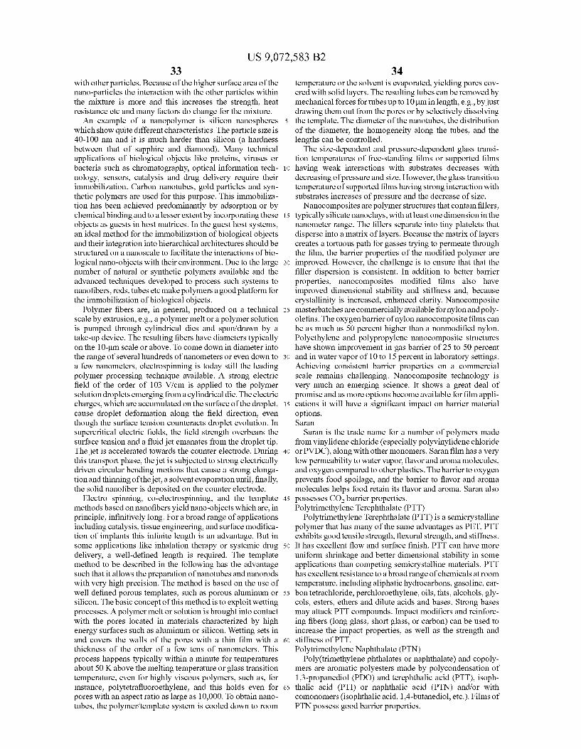
US 9,072,583 B2 33
with other particles. Because of the higher surface area of the nano-particles the interaction with the other particles within the mixture is more and this increases the strength, heat resistance etc and many factors do change for the mixture. An example of a nanopolymer is silicon nanospheres
which show quite different characteristics. The particle size is 40-100 nm and it is much harder than silicon (a hardness between that of sapphire and diamond). Many technical applications of biological objects like proteins, viruses or bacteria Such as chromatography, optical information tech nology, sensors, catalysis and drug delivery require their immobilization. Carbon nanotubes, gold particles and Syn thetic polymers are used for this purpose. This immobiliza tion has been achieved predominantly by adsorption or by chemical binding and to a lesser extent by incorporating these objects as guests in host matrices. In the guest host systems, an ideal method for the immobilization of biological objects and their integration into hierarchical architectures should be structured on a nanoscale to facilitate the interactions of bio logical nano-objects with their environment. Due to the large number of natural or synthetic polymers available and the advanced techniques developed to process Such systems to nanofibers, rods, tubes etc make polymers a good platform for the immobilization of biological objects.
Polymer fibers are, in general, produced on a technical scale by extrusion, e.g., a polymer melt or a polymer Solution is pumped through cylindrical dies and spun/drawn by a take-up device. The resulting fibers have diameters typically on the 10-um scale or above. To come down in diameter into the range of several hundreds of nanometers or even down to a few nanometers, electrospinning is today still the leading polymer processing technique available. A strong electric field of the order of 103 V/cm is applied to the polymer Solution droplets emerging from a cylindrical die. The electric charges, which are accumulated on the Surface of the droplet, cause droplet deformation along the field direction, even though the Surface tension counteracts droplet evolution. In supercritical electric fields, the field strength overbears the Surface tension and a fluid jet emanates from the droplet tip. The jet is accelerated towards the counter electrode. During this transport phase, the jet is subjected to strong electrically driven circular bending motions that cause a strong elonga tion and thinning of the jet, a solvent evaporation until, finally, the solid nanofiber is deposited on the counter electrode.
Electro spinning, co-electrospinning, and the template methods based on nanofibers yield nano-objects which are, in principle, infinitively long. For a broad range of applications including catalysis, tissue engineering, and Surface modifica tion of implants this infinite length is an advantage. But in Some applications like inhalation therapy or systemic drug delivery, a well-defined length is required. The template method to be described in the following has the advantage Such that it allows the preparation of nanotubes and nanorods with very high precision. The method is based on the use of well defined porous templates, such as porous aluminum or silicon. The basic concept of this method is to exploit wetting processes. A polymer melt or solution is brought into contact with the pores located in materials characterized by high energy Surfaces such as aluminum or silicon. Wetting sets in and covers the walls of the pores with a thin film with a thickness of the order of a few tens of nanometers. This process happens typically within a minute for temperatures about 50 K above the melting temperature or glass transition temperature, even for highly viscous polymers, such as, for instance, polytetrafluoroethylene, and this holds even for pores with an aspect ratio as large as 10,000. To obtain nano tubes, the polymer/template system is cooled down to room
10
15
25
30
35
40
45
50
55
60
65
34 temperature or the solvent is evaporated, yielding pores cov ered with solid layers. The resulting tubes can be removed by mechanical forces for tubes up to 10um in length, e.g., by just drawing them out from the pores or by selectively dissolving the template. The diameter of the nanotubes, the distribution of the diameter, the homogeneity along the tubes, and the lengths can be controlled. The size-dependent and pressure-dependent glass transi
tion temperatures of free-standing films or Supported films having weak interactions with Substrates decreases with decreasing of pressure and size. However, the glass transition temperature of supported films having strong interaction with Substrates increases of pressure and the decrease of size.
Nanocomposites are polymer structures that contain fillers, typically silicate nanoclays, with at least one dimension in the nanometer range. The fillers separate into tiny platelets that disperse into a matrix of layers. Because the matrix of layers creates a tortuous path for gasses trying to permeate through the film, the barrier properties of the modified polymer are improved. However, the challenge is to ensure that that the filler dispersion is consistent. In addition to better barrier properties, nanocomposites modified films also have improved dimensional stability and stiffness and, because crystallinity is increased, enhanced clarity. Nanocomposite masterbatches are commercially available for nylon and poly olefins. The oxygenbarrier of nylon nanocomposite films can be as much as 50 percent higher than a nonmodified nylon. Polyethylene and polypropylene nanocomposite structures have shown improvement in gas barrier of 25 to 50 percent and in water vapor of 10 to 15 percent in laboratory settings. Achieving consistent barrier properties on a commercial scale remains challenging. Nanocomposite technology is very much an emerging science. It shows a great deal of promise and as more options become available for film appli cations it will have a significant impact on barrier material options. Saran
Saran is the trade name for a number of polymers made from vinylidene chloride (especially polyvinylidene chloride or PVDC), along with other monomers. Saran film has a very low permeability to water vapor, flavor and aroma molecules, and oxygen compared to other plastics. The barrier to oxygen prevents food spoilage, and the barrier to flavor and aroma molecules helps food retain its flavor and aroma. Saran also possesses CO barrier properties. Polytrimethylene Terephthalate (PTT)
Polytrimethylene Terephthalate (PTT) is a semicrystalline polymer that has many of the same advantages as PET. PTT exhibits good tensile strength, flexural strength, and stiffness. It has excellent flow and surface finish. PTT can have more uniform shrinkage and better dimensional stability in some applications than competing semicrystalline materials. PTT has excellent resistance to a broad range of chemicals at room temperature, including aliphatic hydrocarbons, gasoline, car bon tetrachloride, perchloroethylene, oils, fats, alcohols, gly cols, esters, ethers and dilute acids and bases. Strong bases may attack PTT compounds. Impact modifiers and reinforc ing fibers (long glass, short glass, or carbon) can be used to increase the impact properties, as well as the strength and Stiffness of PTT. Polytrimethylene Naphthalate (PTN)
Poly(trimethylene phthalates or naphthalate) and copoly mers are aromatic polyesters made by polycondensation of 1,3-propanediol (PDO) and terephthalic acid (PTT), isoph thalic acid (PTI) or naphthalic acid (PTN) and/or with comonomers (isophthalic acid, 1,4-butanediol, etc.). Films of PTN possess good barrier properties.

US 9,072,583 B2 35
Polyethylene Naphthalate (PEN) Polyethylene naphthalate (PEN) is a polyester with good
barrier properties (even better than polyethylene terephtha late). Because it provides a very good oxygen barrier, it is particularly well-suited for bottling beverages that are sus ceptible to oxidation, such as beer. It is prepared from ethyl ene glycol and one or more naphthalenedicarboxylic acids by condensation polymerization. Polyurethane A polyurethane is any polymer consisting of a chain of
organic units joined by urethane(carbamate) links. Polyure thane polymers are formed through step-growth polymeriza tion by reacting a monomer containing at least two isocyanate functional groups with another monomer containing at least two hydroxyl(alcohol) groups in the presence of a catalyst. Polyurethane formulations cover an extremely wide range of stiffness, hardness, and densities. Though the properties of the polyurethane are determined mainly by the choice of polyol, the diisocyanate exerts some influence, and must be suited to the application. The cure rate is influenced by the functional group reactivity and the number of functional iso cyanate groups. The mechanical properties are influenced by the functionality and the molecular shape. The choice of diisocyanate also affects the stability of the polyurethane upon exposure to light. Polyurethanes made with aromatic diisocyanates yellow with exposure to light, whereas those made with aliphatic diisocyanates are stable. Softer, elastic, and more flexible polyurethanes result when linear difunc tional polyethylene glycol segments, commonly called poly ether polyols, are used to create the urethane links. This strategy is used to make spandex elastomeric fibers and soft rubber parts, as well as foam rubber. More rigid products result if polyfunctional polyols are used, as these create a three-dimensional cross-linked structure which, again, can be in the form of a low-density foam. Polyether Block Amide (Pebax(R)
Polyether block amide is a thermoplastic elastomer or a flexible polyamide without plasticizer consisting of a regular linear chain of rigid polyamide segments and flexible poly ether segments. Parylene C
Parylene is the tradename for a variety of chemical vapor deposited poly(p-xylylene)polymers used as moisture barri ers and electrical insulators. Among them, Parylene C is the most popular due to its combination of barrier properties, cost, and other manufacturing advantages. Silicone
Silicones, also referred to as polymerized siloxanes or pol ysiloxanes, are mixed inorganic-organic polymers with the chemical formula R2SiO, where R is an organic group Such as methyl, ethyl, or phenyl. These materials consist of an inorganic silicon-oxygenbackbone (... —Si-O-Si-O- Si-O-...) with organic side groups attached to the silicon atoms, which are four-coordinate. In some cases organic side groups can be used to link two or more of these —Si-O- backbones together. By varying the —Si-O- chain lengths, side groups, and crosslinking, silicones can be Syn thesized with a wide variety of properties and compositions. They can vary in consistency from liquid to gel to rubber to hard plastic. The most common siloxane is linear polydim ethylsiloxane (PDMS), a silicone oil. The second largest group of silicone materials is based on silicone resins, which are formed by branched and cage-like oligosiloxanes. Fabrication of the Composite Wall The various layers of the composite wall, including the
CO barrier layers, need not be situated in any particular order, but those of Superior resistance to acidity, temperature,
10
15
25
30
35
40
45
50
55
60
65
36 mechanical abrasion, and Superior biocompatibility profile are preferably employed as layers contacting the gastric envi ronment. Those with Superior resistance to, e.g., acidity and temperature, are preferably employed as layers contacting the central lumen of the balloon. The various layers of the wall can include a single layer or
up to 10 or more different monolayers; however, a film thick ness of from 0.001 inches (0.00254 cm) to 0.0025 inches (0.00635 cm) thick is desirable such that the resulting balloon compacted to fit into a Swallowable capsule. The resulting composite wall preferably has good performance specifica tions with respect to each category listed in Table 1.
Films that are co-extruded are advantageously employed, as some adhesives may contain leachables that are undesir able from a biocompatibility perspective. In addition, coex trusion allows for better blending such that the materials maintain their original properties when combined in this fash ion and are less likely to be subject to delamination when exposed to gastric motility forces. Combining films with similar properties, e.g., two film
layers with excellent CO, barrier properties, in a composite wall is advantageous for use in a gastric balloon containing CO as the inflation gas. A primary advantage of such com posite films is that restrictions on film thickness can be observed without sacrifice of CO retention properties. Such a configuration also contributes to reducing the effects of processing damage (e.g., manufacturing and compacting) and damage due to exposure to in vivo conditions (e.g., gas tric motility forces).
In a particularly preferred embodiment, the composite wall includes a plurality of layers. The first layer is an outer pro tective layer that is configured for exposure to the gastric environment. This layer is resistant to mechanical forces, exposure to water (vapor), abrasion, and high acidity levels. Polyethylene terephthalate is particularly preferred for the layer exposed to the gastric environment, and is especially resistant to water and humidity. The underside of the PET layer is provided with a coating of SiOx as a CO barrier. The SiOx barrier is typically about 100 A thick to about 800 A thick, preferably about 200 A to about 500 A thick. SiOx layers that exceed 800 A are found to be less advantageous; however, in certain embodiments they may be acceptable. A layer of EVOH sandwiched between two layers of LLDPE can be extrusion laminated, co-extruded, or adhesively bonded to the PET-SiOx layer. The EVOH layer is preferably at least 2 microns thick; however, in certain embodiments a thinner layer may be acceptable. Between the PET-SiOx lay ers and the EVOH layer is an adhesive layer, e.g., a dry polyurethane or polyurethane in Solvent, or a low density polyethylene tie layer can be provided to increase the surface activity. Alternatively, corona treatment can be employed. Laminating or adhesive bonding can be employed to prepare a flat sheet composite wall. This preferred design is advanta geous as the EVOH layer can compensate for CO, barrier properties lost in the SiOX application during processing: however, the EVOH layer may not be sufficient when used alone (without SiOx or another CO barrier layer) since the EVOH layer loses CO barrier properties due to water ingress and humidity. The EVOH and SiOx barrier layers are there fore complimentary to each other in maintaining a CO loss of less than 40 cc/m/day.
In a particularly preferred embodiment, the EVOH layer is sanwiched between layers of PE, so as to protect the EVOH layer from ambient water, humidity, or other conditions that can be detrimental to its structural integrity.
In an alternative embodiment, polyurethane is RF welded to saran to yield a 6-7 mil thick composite wall. In another
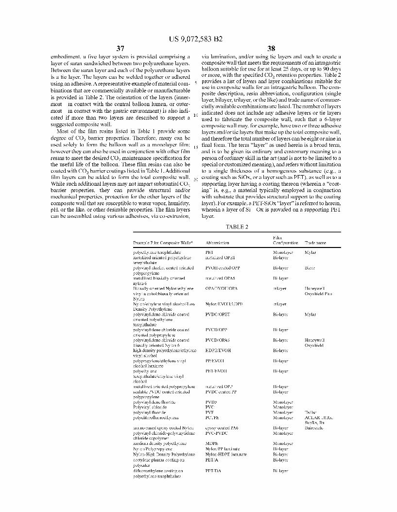
US 9,072,583 B2 37
embodiment, a five layer system is provided comprising a layer of Saran Sandwiched between two polyurethane layers. Between the saran layer and each of the polyurethane layers is a tie layer. The layers can be welded together or adhered using an adhesive. A representative example of material com binations that are commercially available or manufacturable is provided in Table 2. The orientation of the layers (inner most—in contact with the central balloon lumen, or outer most—in contact with the gastric environment) is also indi cated if more than two layers are described to support a Suggested composite wall. Most of the film resins listed in Table 1 provide some
degree of CO barrier properties. Therefore, many can be used solely to form the balloon wall as a monolayer film; however they can also be used in conjunction with other film resins to meet the desired CO maintenance specification for the useful life of the balloon. These film resins can also be coated with CO barrier coatings listed in Table 1. Additional film layers can be added to form the total composite wall. While such additional layers may not impart substantial CO barrier properties, they can provide structural and/or mechanical properties, protection for the other layers of the composite wall that are Susceptible to water vapor, humidity, pH, or the like, or other desirable properties. The film layers can be assembled using various adhesives, via co-extrusion,
5
10
15
38 via lamination, and/or using tie layers and Such to create a composite wall that meets the requirements of an intragastric balloon suitable for use for at least 25 days, or up to 90 days or more, with the specified CO, retention properties. Table 2 provides a list of layers and layer combinations suitable for use in composite walls for an intragastric balloon. The com posite description, resin abbreviation, configuration (single layer, bilayer, trilayer, or the like) and trade name of commer cially available combinations are listed. The number of layers indicated does not include any adhesive layers or tie layers used to fabricate the composite wall, such that a 6-layer composite wall may, for example, have two or three adhesive layers and/or tie layers that make up the total composite wall, and therefore the total number of layers can be eight or nine in final form. The term “layer” as used herein is a broad term, and is to be given its ordinary and customary meaning to a person of ordinary skill in the art (and is not to be limited to a special or customized meaning), and refers without limitation to a single thickness of a homogenous Substance (e.g., a coating Such as SiOX, or a layer Such as PET), as well as to a Supporting layer having a coating thereon (wherein a "coat ing' is, e.g., a material typically employed in conjunction with Substrate that provides structural Support to the coating layer). For example, a PET-SiOx “layer is referred to herein, wherein a layer of Si-Ox is provided on a supporting PET layer.
TABLE 2
Film Example Film Composite Walls* Abbreviation Configuration Trade name
polyethylene terephthalate PET Monolayer Mylar metalized oriented polyethylene metalized OPET Bi-layer erephthalate polyvinyl alcohol coated oriented PWOH coated OPP Bi-layer Bicor polypropylene metallized biaxially oriented metalized OPA6 Bi-layer nylon 6 Biaxally oriented Nyloniethylene OPAfEVOHAOPA rilayer Honeywell vinyl alcohol/biaxially oriented Oxyshield Plus Nylon Nyloniethylene vinyl alcohol/Low Nylon/EVOHILDPE rilayer Density Polyethylene polyvinylidene chloride coated PVDCOPET Bi-layer Mylar oriented polyethylene erephthalate polyvinylidene chloride coated PVCD, OPP Bi-layer oriented polypropylene polyvinylidene chloride coated PVCD, OPA6 Bi-layer Honeywell biaxally oriented Nylon 6 Oxyshield high density polyethylene ethylene HDPEEVOH Bi-layer vinyl alcohol polypropylene/ethylene vinyl PPEVOH Bi-layer alcohol laminate polyethylene PETEVOH Bi-layer erephthalate? ethylene vinyl alcohol metallized oriented polypropylene metalized OPP Bi-layer sealable PVDC coated oriented PVDC coated PP Bi-layer polypropylene polyvinylidene fluoride PVDF Monolayer Polyvinyl chloride PVC Monolayer polyvinyl fluoride PVF Monolayer Tedlar polychlorofluoroethylene PCTFE Monolayer ACLARUltRx,
SupRX, RX amine-based epoxy coated Nylon epoxy coated PA6 Bi-layer Bairocade polyvinyl chloride-polyvinylidene PVC-PVDC Monolayer chloride copolymer medium density polyethylene MDPE Monolayer Nylon/Polypropylene Nylon/PP laminate Bi-layer Nylon-High Density Polyethylene Nylon-HDPE laminate Bi-layer acetylene plasma coating on PETA Bi-layer polyester difluoroethylene coating on PETDA Bi-layer polyethylene terephthalate
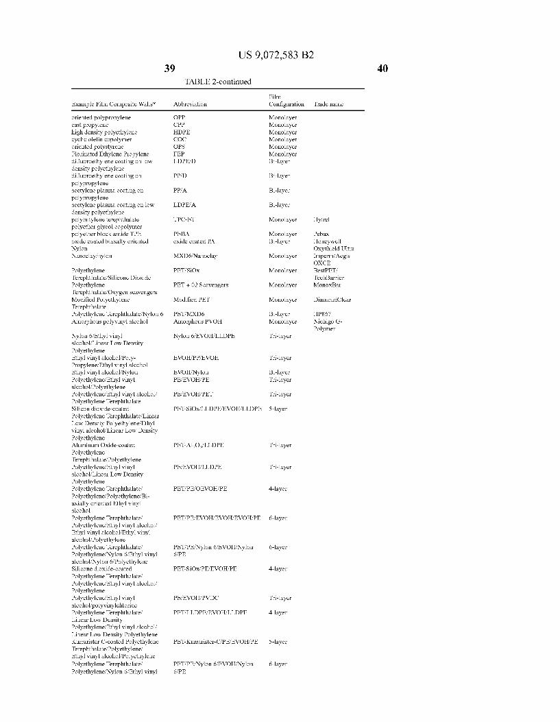
Example Film Composite Walls*
oriented polypropylene cast propylene high density polyethylene cyclic olefin copolymer oriented polystyrene Florinated Ethylene Propylene difluoroethylene coating on low density polyethylene difluoroethylene coating on polypropylene acetylene plasma coating on polypropylene acetylene plasma coating on low density polyethylene polybutylene terephthalate polyether glycol copolymer polyether block amide TPE oxide coated biaxally oriented Nylon Nanoclay nylon
Polyethylene Terephthalate/Silicone Dioxide Polyethylene Terephthalate. Oxygen scavengers Modified Polyethylene Terephthalate Polyethylene Terephthalate/Nylon 6 Amorphous polyvinyl alcohol
Nylon 6/Ethyl vinyl alcohol/Linear Low Density Polyethylene Ethyl vinyl alcohol/Poly Propylene/Ethyl vinyl alcohol Ethyl vinyl alcohol/Nylon Polyethylene/Ethyl vinyl alcohol/Polyethylene Polyethylene/Ethyl vinyl alcohol/ Polyethylene Terephthalate Silicon dioxide-coated Polyethylene Terephthalate/Linear Low Density Polyethylene/Ethyl vinyl alcohol/Linear Low Density Polyethylene Aluminum Oxide-coated Polyethylene Terephthalate/Polyethylene Polyethylene/Ethyl vinyl
ohol/Linear Low Density Polyethylene
yethylene Terephthalate? Polyethylene? Polyethylene/Bi axially oriented Ethyl vinyl alcohol Polyethylene Terephthalate? Polyethylene/Ethyl vinyl alcohol/ Ethyl vinyl alcohol/Ethyl vinyl alcohol/Polyethylene Polyethylene Terephthalate? Polyethylene, Nylon 6/Ethyl vinyl alcohol/Nylon 6/Polyethylene Silicone dioxide-coated Polyethylene Terephthalate? Polyethylene/Ethyl vinyl alcohol/ Polyethylene Polyethylene/Ethyl vinyl alcohol/polyvinylchloride Polyethylene Terephthalate? Linear Low Density Polyethylene/Ethyl vinyl alcohol/ Linear Low Density Polyethylene Kurrarister C-coated Polyethylene Terephthalate/Polyethylene? Ethyl vinyl alcohol/Polyethylene Polyethylene Terephthalate? Polyethylene, Nylon 6/Ethyl vinyl
US 9,072,583 B2 39
TABLE 2-continued
bbreviation
PP PP DPE
E DPED
PPD
PPA
LDPEA
TPC-ET
PEBA oxide coated PA
MXD6/Nanoclay
PETSiOx
PET + 02 Scavengers
Modified PET
PETMXD6 Amorphous PVOH
Nylon 6/EVOHILLDPE
EVOHAPPEVOH
EVOHNylon PEEVOHPE
PEEVOHPET
PETSiOxLLDPEEWOHRLLDPE
PETAl-O/LLDPE
PEEVOHLLDPE
PETAPEOEVOHPE
PETAPEEVOHEVOHEVOHPE
PET/PE/Nylon 6/EVOHNylon 6PE
PETSiOxPEEVOHPE
PEEVOHPVDC
PETLLDPEEVOHNLLDPE
PET-Kurrarister-CPEEVOHAPE
PET/PE/Nylon 6/EVOHNylon 6PE
Film Configuration
Monolayer Monolayer Monolayer Monolayer Monolayer Monolayer Bi-layer
Bi-layer
Bi-layer
Bi-layer
Monolayer
Monolayer Bi-layer
Monolayer
Monolayer
Monolayer
Monolayer
Bi-layer Monolayer
Tri-layer
Tri-layer
Bi-layer Tri-layer
Tri-layer
5-layer
Tri-layer
Tri-layer
4-layer
6-layer
6-layer
4-layer
Tri-layer
4-layer
5-layer
6-layer
Trade name
Hytrel
Pebax Honeywell Oxyshield Ultra mperm Aegis OXCE BestPET, TechBarrier MonoxBar
DiamondClear
HP867 Nichigo G Polymer
40

US 9,072,583 B2 41
TABLE 2-continued
Example Film Composite Walls* Abbreviation
alcohol/Nylon 6/Polyethylene Nylon 6/Ethyl vinyl alcohol Nylon 6/EVOH/PVDC/Nylon Polyvinylchloride/Low Density 6.LDPE Polyethylene Polyimide PI Polyimide/Linear Low Density PILLDPE Polyethylene Polyimide/Polyvinylchloride PIPVdC Polyimide/Polyvinylchloride? PIPVdCLLDPE Linear Low Density Polyethylene
For all combinations where LLDPE, P (LDPE), High Density Polyethylene (H
In particularly preferred embodiments, the composite wall has a thickness of 0.0025 inches or less (2.5 mill or less); however, in certain embodiments a thicker composite wall may be acceptable. Generally it is preferred that the compos ite wall have a thickness of up to 0.002 inches (2 mil), or up to 0.0021 inches (2.1 mil). Swallowable, Self-Inflating, Intragastric Balloon System A Swallowable, self-inflating intragastric balloon system
according to selected preferred embodiments includes the following components: a balloon in a deflated and compacted state (“balloon'); an inner capsule or other container (“inner container) that contains one or more CO2 generating com ponents and that is present inside the lumen of the balloon; and an outer capsule, container, or coating ("outer container) that contains the balloon. The balloon further comprises a self-sealing valve system, preferably attached to the inner Surface of the balloon by an adhesive or other means (e.g., welding), and an inoculation spacer to prevent puncture of the wall of the balloon and inner container by a needle or other means for injecting an liquid activation agent into the lumen of the balloon via the self-sealing valve. The outer container preferably incorporates the balloonina compacted State (e.g., folded and rolled) with sufficient space to allow for activation liquid to be injected into the balloon. The liquid activation agent initiates separation, erosion, degradation, and/or disso lution of the inner container and generation of CO upon contact with the inflation agent contained within the inner container, which Subsequently causes outer container separa tion, erosion, degradation, and/or dissolution due to CO gas pressure.
FIG. 2A depicts selected components of a swallowable, self-inflating intragastric balloon system of a preferred embodiment, including a silicone head 441 with radioopacity ring 442, trimmed 30 D silicone septum 443, Nylon 6 inocu lation spacer 444, compacted balloon 445, inner container 446, and outer container 447 as constituents of the system in unassembled form. FIG. 2B depicts a fully assembled outer container 447 including vent hole 448 aligned with septum 449 for puncture to inject liquid activation agent. As dis cussed further below, the components of particularly pre ferred systems possess the attributes described herein; how ever, in certain embodiments systems can be employed which utilize components having other attributes and/or values.
Balloon The balloon is fully sealed 360 degrees around with no
external opening or orifice to the central lumen. The balloon has an “inverted configuration. The term “inverted as used herein is a broad term, and is to be given its ordinary and customary meaning to a person of ordinary skill in the art (and is not to be limited to a special or customized meaning), and refers without limitation to a balloon having a smooth exter
Film Configuration
42
Trade name
5-layer
Monolayer Bi-layer
Bi-layer Bi-layer
25
30
35
40
45
50
55
60
65
DPE, or LDPE is suggested, the polyethylene can alternatively be Low Density Polyethylene E), or Linear Low Density Polyethylene (LLDPE), Particularly preferred is LLDPE.
nal surface with seams, welds, or the inside the balloon. In order to create a balloon with an inverted configuration, e.g., a balloon with no external seam allowance (no wall material between the edge of the balloon and the weld, seam, or other feature joining the sides together), two balloon halves are joined together in some fashion (e.g., adhered using adhesive or heat or the like based on the balloon material used). One of the balloon halves encompasses an opening to allow for the balloon to be pulled through itself after adherence of the two halves and to have the seams of the balloon on the inside. The opening created is preferably circular but can be any similar shape, and the diameter of the opening preferably does not exceed 3.8 cm; however, in certain embodiments a larger diameter may be acceptable. A patch of material is adhered (adhesively, heat welded, or the like, based on the material used) to cover the original balloon-half opening. The inver sion hole thus created that is Subsequently patched is Small enough that the forces exerted during inflation do not com promise the material used to maintain CO gas in the balloon. The preferred shape for the inflated balloon in final assembly is ellipsoid, preferably spheroid or oblate spheroid, with nominal radii of from 1 inch (2.5 cm) to 3 inches (7.6 cm), a nominal height of from 0.25 inches (0.6 cm) to 3 inches (7.6 cm), a volume of from 90 cm to 350 cm (at 37° C. and at internal nominal pressure and/or full inflation), an internal nominal pressure (at 37°C.) of 0 psi (0 Pa) to 15 psi (103421 Pa), and a weight of less than 15 g. The balloon is configured for self-inflation with CO and is configured to retain more than 75% of the original nominal volume for at least 25 days, preferably for at least 90 days when residing in the stomach. A self-sealing valve system is attached to the balloon (e.g.,
on its inside Surface) without the use of an opening, orifice, or other conduit in the wall of the balloon. The valve system utilizes a septum with a durometer of 20 Shore A to 60 Shore D. The valve is inserted or otherwise fabricated into a retain ing structure that has a higher durometer, e.g., 40 Shore D to 70 Shore D or more. The retaining structure is fabricated from a silicone, rubber, Soft plastic or any suitable non-metallic polymeric material Such as an acrylic, an epoxy, a thermo plastic elastomer, or thermoplastic polyurethane. Preferably, a structure. Such as a ring, that is metallic or non-metallic but radioopaque (e.g., barium) and visible under X-ray, is embed ded in the retaining structure. Using a mechanical fit mecha nism of two structures of different durometers, one softer (septum) with a large diameter, is inserted into a Snug, more rigid durometer structure creates compressive forces in the once open orifice to enable CO, retention and reduce suscep tibility for CO gas leaks. The metallic ring for radio-opacity also helps to create compressive forces on the septum. The self-sealing septum allows air to be evacuated from the bal loon for processing/compacting and inserting in the outer

US 9,072,583 B2 43
container, and also allows for the inflation agent to be injected into the outer container for inflation initiation. Additional septums can be provided, if desired; however, it is generally preferred to employ a single septum So as to maintain the volume of the deflated/folded balloon (and thus the outer capsule) as Small as possible. The valve system is preferably attached to the inner surface of the balloon such that a shear force greater than 9 lbs (40N) is required to dislodge the valve system. The septum can be wedge-shaped.
Inner Container The inner container is contained within the lumen of the
balloon and contains the CO generator for balloon self-in flation. The CO generator comprises an inflation agent mix ture housed within the container. Preferably, from about 10% to about 80% of the total inflation agent used comprises powdered citric acid, with the remainder comprising pow dered sodium bicarbonate. Sufficient inflation agent is pro vided such that upon completion of the CO generating reac tion, the balloon achieves inflation at the nominal inflation pressure described above. Preferably, a total of from about 0.28 to 4 grams inflation agent mixture is employed, depend ing upon the balloon size to be inflated; preferably up to 1.15 grams of Sodium bicarbonate is used with the remainder being powdered citric acid to generate 300 cm of CO., at nominal pressure. The inflation agent is compressed, formed or otherwise
held in a shape which provides good Surface area availability for the reactants for CO generation, while minimizing the space and/or Volume Sufficient to hold the inner container. Preferably, the inner container has a length (longest dimen sion) of from about 0.748 inches (1.9 cm) to 1.06 inches (2.7 cm) and a diameter or width of from about 0.239 inches (0.6 cm) to about 0.376 inches (1 cm). The volume of the inner container is preferably from about 0.41 ml to about 1.37 ml. The inner container is preferably in the form of a standard gelatin capsule but a gelatin tape may be used in lieu of a push fit capsule. The container is preferably relied upon for con taining the inflation agent; however, additional sealing or other encapsulation can be employed to control timing of inflation. Gelatin is particularly preferred for use as the inner container; however other materials can also be suitable for use, e.g., cellulose. In order to minimize the internal Volume of the system, it is generally preferred to include only a single inner container; however, in certain embodiments two or more internal containers can advantageously be employed. Timing of self-inflation is selected based on a normal esoph ageal transit time and a normal time of gastric emptying of large food particles, such that the balloon does not inflate to a size that would block the esophageal passageway or prema turely pass through the pyloric sphincter. Timing is also derived by compacting the balloon Such that the activation agentis Substantially localized in the balloon next to the inner capsule, creating an efficient CO Self-inflation method. I was able to get through the body this evening and attached are a few edits (very minor). Balloon inflation is initiated by the liquid activation agent causing degradation of the inner con tainer, such that the inflation agent in the inner container contacts the liquid activation agent, thereby initiating the gas generation reaction. An inoculation spacer is preferably incorporated to guide a
needle into the self-sealing valve for injection of liquid acti vation agent into the lumen of the balloon and to prevent the needle from penetrating the wall of the deflated/folded bal loon elsewhere such that pressure within the lumen of the balloon cannot be maintained. The inoculation spacer also facilitates preventing liquid activation agent from penetrating the inner container or the folded balloon material, thereby
10
15
25
30
35
40
45
50
55
60
65
44 focusing the activation agent in an appropriate manner to properly mix the reactants for CO generation according to the criteria described above. The inoculation spacer is gener ally in the form of a tube or cylinder. The inoculation spacer is preferably attached to the inner container and/or the self sealing valve system with an adhesive or other fixing means; however, in certain embodiments the inoculation spacer can be “free-floating and maintained in position by the folding or rolling of the walls of the balloon. The inoculation spacer can comprise any Suitable material that can be passed after sepa ration, erosion, degradation, digestion, and/or dissolution of the outer container; however, preferable materials include non-metallic materials with a minimum Shore D durometer of 40 or more, any metallic material, or a combination thereof. A cupped needle stop (inoculation spacer) can advanta geously be employed.
Outer Container The balloon is preferably provided in a deflated and folded
state in a capsule or other retaining, containing or coating structure (“outer container). The outer container is prefer ably in the form of a standard push-fit gelatin capsule, with the push-fit relied upon for containing the deflated/folded balloon; however, a gelatin wrap can advantageously be employed in certain embodiments. Gelatin is particularly pre ferred for use as the outer container; however other materials can also be suitable for use, e.g., cellulose, collagen, and the like. Preferably, the outer container has a length (longest dimension) of from about 0.95 inches (2.4 cm) to 2.5 inches (6.3 cm) and a diameter or width of from about 0.35 inches (0.9 cm) to about 0.9 inches (2.4 cm). The volume of the inner container is preferably from about 1.2 ml to about 8.25 ml. The outer container is preferably configured with one or more holes, slits, passageways or otheregresses, preferably on each end, which act as vents such that any gas created due to inflation agent exposure to condensation or other ambient moisture present during processing does not cause premature separation or degradation of the inner container prior to 30 seconds after inoculation of the liquid activation agent, which may have an undesirable effect on reaction efficiency. The outer capsule degrades (e.g., separates, dissolves, or other wise opens) due to pressure buildup caused by inflation of the balloon.
Inflation The Swallowable, self-inflating intragastric balloon is pro
vided with mechanisms to reliably control timing of self inflation Such that premature inflation while in the esophagus during Swallowing is avoided and Sufficient inflation once in the stomach so as to prevent passage through the pyloric sphincter is ensured. Normal esophageal transit time for large food particles has been documented as 4-8 seconds, and gas tric emptying of large food particles through the pylorus does not occur for at least 15-20 minutes. The outer container is preferably configured to separate, dissolve, degrade, erode, and/or otherwise allow the deflated/folded balloon to begin unfolding not less than 60 seconds but not more than 15 minutes after inoculation with liquid activation agent. The inner container is preferably configured chemically, mechanically or a combination thereof to retard the initial CO generating chemical reaction Such that Sufficient CO to begin inflating the balloon is not available earlier than 30 seconds after inoculation with the liquid activation agent, but to permit generation of sufficient CO such that at least 10% of the occupyable volume of the balloon is filled within 30 minutes, at least 60% of the occupyable volume of the balloon is filled within 12 hours, and at least 90% of the occupyable volume of the balloon is filled within 24 hours. This timing allows for injection of the activation agent into the outer

US 9,072,583 B2 45
container by the medical professional, passing the device to the patient, and Swallowing by normal peristaltic means by the patient. This timing also prohibits potential passing of an uninflated balloon into the duodenum by the balloon being inflated to a Sufficient size such that gastric emptying of the balloon would not be easy, as objects more than 7 mm in diameter do not readily pass. The activation agent is preferably injected using a Syringe
having a needle with a gauge diameter of from 25 to 32. The needle length is preferably from about 0.25 inches (0.6 cm) to 1 inches (2.54 cm) in length so as to create a flow rate that allows for delivery of the full volume of inflation agent within 30 seconds, but in a manner/stream/flow that does not physi cally damage the inner container, thereby causing premature CO generation and inflation. The activation agent is prefer ably pure water, or a solution containing up to 50% concen tration of anhydrous citric acid at 20° C., or the equivalent thereof at varying solution temperatures based on Solubility of anhydrous citric acid. Preferably, the system is configured to have an occupyable Void space in the central lumen of the balloon when in compacted form in the outer container of from about 0.3 ml to about 4.5 ml, such that a corresponding Volume of activation agent can be injected into the Void space.
Prior to placement in the outer container of the balloon containing the inner container, the balloon is deflated and folded. In a deflated state, the balloon is flat, with the inverted seam extending around the perimeter of the balloon. The self-sealing valve system is affixed to the inner wall of the lumen close to the center of the deflated balloon, with the inner container positioned adjacent to the self-sealing valve system. The walls of the balloon are then folded. As part of the balloon design, the self-sealing valve system is manufactured in a manner such that it is placed “off center to minimize the number of folds upon themselves (e.g., doubling or tripling up) required to fit the balloon in the outer container. For example, the self-sealing valve system can advantageously be placed /2 rit/4 r from the center of the balloon, wherein ris the radius of the balloon along a line extending from the center of the balloon through the septum.
Prior to folding, the free-floating inner container with infla tion agent for CO2 generation is preferably vertically aligned with the self-sealing valve system Such that the septum/in oculation spacer is placed directly above the tip of the cap Sule. The balloon contains an inner container. A self-sealing valve system is adhesively adhered to the interior of the wall of the balloon, and the inverted configuration of the balloon is provided by inversion through a hole sealed with a patch. The top approximate 4 of the balloon wall is folded over the inner capsule, and the pleats where the capsule is are creased simi lar to the pleats formed in the second step of making a paper airplane, then folded over to the left or to the right. The bottom approximate 34 of the sphere is then accordioned using no more than 2 creases and folded over the capsule. The left half is then folded over the right half of the capsule or vice versa so that the wings touch. Then the material is rolled over until it creates a tight roll. The device is then placed in the outer container. The balloon is folded so as to form a pocket around the
inner capsule is formed to insure that the liquid injected through the self-sealing valve system is contained in an area less than 10% of the entire balloon surface area. The balloon is folded such that the number of total folds is minimized so as to minimize possible damage to the outer material or com promise of CO barrier properties. The number of total folds is preferably less than 10 folds. The balloon material is rolled when at all possible such that the number of creases required to fit the balloon in an outer container is minimized. This is
5
10
15
25
30
35
40
45
50
55
60
65
46 done in effort to also to prevent lumen material damage. The self-sealing valve is also preferably constructed off-center of the balloon so as to minimize the number offolds that layer on top of each other. The material forming the wall of the balloon is processed
and folded to maximize reaction efficiency by localizing the initiation agent injected into the balloon so that it is main tained proximal to the reactants within the inner container. The balloon is folded such that once the reaction initiates and the outer container separates, the balloon unfolds in a manner that creates the largest possible Surface area, which prohibits the balloon from readily passing through the pyloric sphinc ter. The ratio of reactants in the inflation agent and activation agent are selected Such that the pH of any remnant liquid inside the lumen of the balloon is acidic, with a pH of less than 6. Such that any balloon leakage or breach that allows stomach acid to enter does not cause additional CO generation and resulting unintentional re-inflation.
Deflation The Swallowable, self-inflating intragastric balloon is pro
vided with mechanisms to reliably control timing of deflation. In preferred embodiments, the balloon auto-deflates and passes through the stomach, through the lower gastrointesti nal tract, and out of the body. In the preferred embodiments described below, the timing of deflation can be accomplished via the external gastric environment (by conditions of tem perature, humidity, Solubility, and/or pH, for example) or via the environment within the lumen of the inflated balloon.
In other embodiments, the patch applied to allow for inverted seams as described above and/or one or more addi tional patches or other structures added to the balloon con struction are made out of an erodible, degradable, or dissolv able material (natural or synthetic) and are incorporated into the wall of the balloon. The patch(s) are of sufficient size to ensure opening of a Sufficient Surface area to cause rapid deflation, and to prevent re-inflation by seepage of stomach fluid into the balloon. The balloon patch(s) comprise materi als that can be applied to the balloon such that a substantially Smooth Surface is maintained, and preferably comprise a single layer or multi-layered material. The patch(s) are con structed using an erodible, disintegrable, degradable or other Such material that is preferably tissue-compatible and degrades into non-toxic products or is a material that slowly hydrolyzes and/or dissolves over time (e.g., poly(lactic-co glycolic acid) (PLGA), polyvinyl alcohol (PVOH), polylactic acid (PLA), poly-L-lactic acid PLAA, Pullulan, Polyethylene Glycol (PEG), polyanhydrides, polyorthoesters, pol yaryletherketones (PEEK), multi-block polyetheresters, poliglecaprone, polydioxanone, polytrimethylene carbonate, and other similar materials). These erodible, disintegrable, or degradable materials can be used alone, or in combination with other materials, or can be cast into/co-extruded, lami nated, and/or dip coated in conjunction with non-erodible polymers (e.g., PET or the like) and employed in the con struction of the balloon. Degradation/erosion occurs, is initi ated by, and/or is controlled by the gastric environment (e.g., by conditions oftemperature, humidity, solubility, and/or pH, for example), or is controlled within the lumen of the balloon (e.g., by conditions of humidity and/or derived pH, for example) based on what the patch is exposed to. Thickness of the polymeras well as environment which affects degradation and time of exposure can also facilitate degradation timing. Degradation/erosion are timed Such that they occur once the pre-determined balloon useful life is completed (e.g., infla tion is maintained for from 25 to 90 days in vivo in the stomach before degradation/erosion results information of an opening permitting deflation). As an alternative to (or in con

US 9,072,583 B2 47
nection with) using an degradable material for the patch, the patch can comprise a similar CO barrier film or the same film as the remaining wall of the balloon which is adhered to the balloon using a weak adhesive, or welded or adhered such that after a specified amount of time the patch delaminates from the applied area and allows for an opening for CO release for deflation. The mechanism of using an erodible material, or a material that mechanically fails after a pre-specified time is be similar for all embodiments for deflation mechanisms described below as well. The timing of degradation or erosion can be controlled using the external gastric environment (e.g., by conditions oftemperature, humidity, solubility, and/or pH, for example) and/or can be controlled by conditions within the lumen of the balloon (e.g., by conditions of humidity and/or pH of residual liquid in the balloon).
In other embodiments, a plug or plugs (optionally in con junction another degradable retaining structure) can be incor porated into the balloon construction and can consist, all or in part, of an erodible, disintegrable, or otherwise degradable synthetic or natural polymer similar to those described above (e.g., PLGA, PLAA, PEG, or the like). The plug can be formed into various shapes (e.g., cylinder shape) to achieve various Surface-to-volume ratios So as to provide a prese lected and predictable bulk degradation pattern for the erod ible polymer. The plug can incorporate a releasing mecha nism that can be chemically initiated after degradation/ erosion begins, such that the septum or plug material pops out of the balloon or falls inside of the balloon, thereby creating a passageway for CO gas release and subsequent deflation of the balloon. Mechanical additions that can be used in con junction with a plug include a compressed spring housed within the retaining structure or plug structure, or a degrad able? erodible/disintegrable material that holds a plug (e.g., of a nondegradable or degradable material) in place. Once the material degrades, the spring is released and/or the plug/ septum is pulled into the balloon or pushed out of the balloon, thus releasing CO gas once an orifice has been created by release of the spring mechanism and pushing out or pulling in of the plug.
In certain embodiments, the balloon can incorporate one or more plugs in the wall of the balloon that contain a com pressed pellet or gas releasing pellet. The pellet can be com prised of any combination of constituents that, when acti vated, emit CO gas (e.g., sodium bicarbonate and citric acid, or potassium bicarbonate and citric acid, or the like). The pellet can be in tablet or rod form protected by an erodible, disintegrable, or degradable material that is preferably tissue compatible and degrades into non-toxic products or that slowly hydrolyzes and/or dissolves similarly to the plugs and patches described above (e.g., poly(lactic-co-glycolic acid) (PLGA), polyvinyl alcohol (PVOH), polylactic acid (PLA), poly-L-lactic acid PLAA, Pullulan, Polyethylene Glycol, polyanhydrides, polyorthoesters, polyaryletherketones (PEEK), multi-block polyetheresters, poliglecaprone, poly dioxanone, polytrimethylene carbonate, and other like mate rials). Degradation/erosion of the plug initiates the reaction of the two chemicals in the pellet and Subsequently leads to formation of gas (e.g., CO). As sufficient gas is trapped or built up, Sufficient pressure is eventually generated to push out the softened polymer material and create a larger channel for the CO gas in the balloon to escape. External pressure applied by the stomach to the balloon (e.g., Squeezing) can contribute to the process of creating a larger channel. Dimen sions and properties of the plug (diameter, thickness, compo sition, molecular weight, etc.) comprised of the polymer drives the timing of degradation.
5
10
15
25
30
35
40
45
50
55
60
65
48 In other embodiments, plugs or patches of different shapes
or sizes similar to those of the plugs described above can be employed within the balloon lumen in a multi-layer configu ration including a semi-permeable membrane to facilitate balloon deflation. The plug or patch is made of similar degradable/erodible/dissolvable material as described above (e.g., poly(lactic-co-glycolic acid) (PLGA), polyvinyl alco hol (PVOH), polylactic acid (PLA), PLAA, pullulan, and other like materials) and contains a compartment enclosed by a semi-permeable membrane (impermeable to an osmolyte) that contains a concentrated Solution of a solute or osmolyte (such as glucose, Sucrose, other Sugars, salts, or combination thereof). Once the plug or patch begins to degrade or erode, the water molecules move by osmosis down the water gradi ent from the region of greater water concentration to the region of lower water concentration across the semi-perme able membrane into the hypertonic solution in the compart ment. The compartment containing the osmolyte Swells and eventually bursts, pushing the membranes and the degraded plug or patch out, thereby allowing rapid gas loss through the newly created channels or areas.
Another mechanism for self-deflation is to create a forced de-lamination scheme, which can provide a larger Surface area to ensure rapid deflation. In, e.g., a balloon having a tri-layer wall, the outermost layer is substantially strong enough to hold CO (e.g., polyethylene terephthalate (PET) or the like), the middle layer is comprised entirely of an erodible material (e.g., PVOH or the like) while the inner layer is comprised of a weaker material (e.g., polyethylene (PE) or the like). The PET or outermost layer is “scored” or hatched with erodible material to create small channels that erode over time. This creates channels such that the gastric fluid seeps into the balloon layers and starts degrading the fully erodible material. When the erodible layer degrades or dissolves, the material that composes the innermost layer also erodes, degrades or dissolves since it is not strong enough to withstand the gastric forces/environment on its own. The balloon then collapses on itself and eventually passes through the lower gastrointestinal tract. Having an erodible layer sandwiched between a strong and weak layer facilitates tim ing of erosion by creating a longer path length than an erod ible plug or patch affected by the gastric environment. The distance between scores or openings can also be selected so as to provide a desired deflation rate. A mechanism to facilitate passing involves an erosion
mechanism that allows for the balloon to be broken down into a size that has a higher probability of predictably passing through the lower gastrointestinal system. Preferably, the size of the balloon as deflated is less than 5 cm long and 2 cm thick (similar to various foreign objects of similar size that have been shown to pass predictably and easily through the pyloric sphincter). This can be accomplished by providing the bal loon with "erodible seams'. One seam that breaks the balloon open into (at a minimum) two halves, or more seams are provided so that a plurality of smaller balloon pieces is pro duced in the dissociation reaction. The number of seams used can be selected based on the original Surface area of the balloon and what is required to dissociate the balloon into pieces that are of a size that can predictably pass through the gastrointestinal tract more easily. The rate of seam erosion can be controlled by using a material affected by, e.g., the external gastric environment pH, liquid, humidity, tempera ture, or a combination thereof Seams can be single layer consisting of only erodible material, or multi-layer. The tim ing of self-deflation can be further controlled by the design of the seam layers, e.g., making the reaction and/or degradation of the seam material dependent on the internal environment of
US 9,072,583 B2 49
the balloon instead of the external environment. By manipu lating the reaction Such that erosion or degradation is initiated by the internal environment (e.g., the balloons internal pH, humidity, or other factors), any impact of person-to-person gastric variability (pH, etc.) that could affect erosion timing is minimized. The internal balloon environment can be manipu lated by adding excess water at injection to create a more humid internal environment, or the amount of constituents added can be varied to manipulate the pH, etc. The present invention has been described above with ref
erence to specific embodiments. However, other embodi ments than the above described are equally possible within the scope of the invention. Different method steps than those described above, performing the method by hardware or soft ware, may be provided within the scope of the invention. The different features and steps of the invention may be combined in other combinations than those described. The scope of the invention is only limited by the appended patent claims.
All references cited herein are incorporated herein by ref erence in their entirety. To the extent publications and patents or patent applications incorporated by reference contradict the disclosure contained in the specification, the specification is intended to Supersede and/or take precedence over any Such contradictory material.
To the extent publications and patents or patent applica tions incorporated by reference herein contradict the disclo Sure contained in the specification, the specification is intended to Supersede and/or take precedence over any Such contradictory material.
Unless otherwise defined, all terms (including technical and scientific terms) are to be given their ordinary and cus tomary meaning to a person of ordinary skill in the art, and are not to be limited to a special or customized meaning unless expressly so defined herein.
Terms and phrases used in this application, and variations thereof, unless otherwise expressly stated, should be con Strued as open ended as opposed to limiting. As examples of the foregoing, the term including should be read to mean including, without limitation or the like; the term compris ing as used herein is synonymous with including, contain ing, or characterized by, and is inclusive or open-ended and does not exclude additional, unrecited elements or method steps; the term example is used to provide exemplary instances of the item in discussion, not an exhaustive or limiting list thereof adjectives such as known, normal, standard, and terms of similar meaning should not be con Strued as limiting the item described to a given time period or to an item available as of a given time, but instead should be read to encompass known, normal, or standard technologies that may be available or known now or at any time in the future; and use of terms like preferably, preferred. desired, or desirable, and words of similar meaning should not be understood as implying that certain features are criti cal, essential, or even important to the structure or function of the invention, but instead as merely intended to highlight alternative or additional features that may or may not be utilized in a particular embodiment of the invention. Like wise, a group of items linked with the conjunction and should not be read as requiring that each and every one of those items be present in the grouping, but rather should be read as and/or unless expressly stated otherwise. Similarly, a group of items linked with the conjunction or should not be read as requiring mutual exclusivity among that group, but rather should be read as and/or unless expressly stated oth erwise. In addition, as used in this application, the articles a and an should be construed as referring to one or more than
10
15
25
30
35
40
45
50
55
60
65
50 one (i.e., to at least one) of the grammatical objects of the article. By way of example, an element means one element or more than one element. The presence in some instances of broadening words and
phrases such as one or more, at least, but not limited to’, or other like phrases shall not be read to mean that the nar rower case is intended or required in instances where Such broadening phrases may be absent.
All numbers expressing quantities of ingredients, reaction conditions, and so forth used in the specification are to be understood as being modified in all instances by the term about. Accordingly, unless indicated to the contrary, the numerical parameters set forth herein are approximations that may vary depending upon the desired properties sought to be obtained. At the very least, and not as an attempt to limit the application of the doctrine of equivalents to the scope of any claims in any application claiming priority to the present application, each numerical parameter should be construed in light of the number of significant digits and ordinary rounding approaches.
Furthermore, although the foregoing has been described in Some detail by way of illustrations and examples for purposes of clarity and understanding, it is apparent to those skilled in the art that certain changes and modifications may be prac ticed. Therefore, the description and examples should not be construed as limiting the scope of the invention to the specific embodiments and examples described herein, but rather to also cover all modification and alternatives coming with the true scope and spirit of the invention.
What is claimed is: 1. An intragastric balloon system comprising a volume
occupying Subcomponent and a deflation Subcomponent, wherein the deflation subcomponent is configured to deflate the intragastric balloon system after a preselected period of time has lapsed since deployment of the system in Vivo, wherein the deflation Subcomponent comprises a biodegrad able or dissolvable head that is configured to, upon degrada tion, allow fluid to escape from the Volume-occupying Sub component, wherein a first portion of the head is configured to degrade faster than a second portion of the head, wherein the first portion of the head is configured to stabilize the second portion of the head such that, in vivo, when the first portion of the head degrades, the second portion of the head destabilizes and is released from the head, thereby accelerating a process of deflation of the Volume occupying Subcomponent, wherein the Volume occupying Subcomponent comprises a composite wall configured to maintain a CO leak rate of less than or equal to 40 cc/m/day at 37°C., wherein the composite wall comprises multiple layers of materials, the multiple layers of materials including:
a polyethylene outer Supporting layer having a Young's Modulus of 500 Mpa or greater and configured to be proximal to the gastric environment or the central lumen of the balloon;
an ethylene vinyl alcohol inner CO barrier layer config ured to not be directly exposed to the gastric environ ment or a central lumen of the balloon, such that its CO barrier properties are not substantially affected by expo sure to humidity levels within the gastric environment or within a central lumen of the balloon;
a nylon inner CO barrier layer configured to not be directly exposed to the gastric environment or a central lumen of the balloon, such that its CO barrier properties are not Substantially affected by mechanical forces during pro cessing, compacting, or application of external gastric pressures; and
US 9,072,583 B2 51
an outer layer on an opposite side of the composite wall from the polyethylene outer Supporting layer,
wherein the intragastric balloon system is configured to retain more than 75% of an original nominal volume in the gastric environment for at least 25 days.
2. The intragastric balloon system of claim 1, wherein the ethylene vinyl alcohol inner CO, barrier layer has a thickness of at least about 2 microns.
3. The intragastric balloon system of claim 1, wherein the ethylene vinyl alcohol inner CO barrier layer is situated between two polyethylene layers, and wherein the ethylene vinyl alcohol inner CO barrier layer and the two polyethyl ene layers are bonded together with tie layers.
4. The intragastric balloon system of claim 1, wherein the intragastric balloon system is configured to be Swallowable, the system further comprising a self-sealing valve system attached to the composite wall of the balloon in a central lumen of the balloon by an adhesive with a shear force greater than about 40N, the self-sealing valve system comprising a septum, a retaining structure, and a continuous ring, wherein the septum has a durometer that is less thana durometer of the retaining structure, wherein the continuous ring is configured to exert a compressive force on the septum, wherein the balloon has a weight of less than about 15 g, wherein the balloon is configured to have a shape upon full inflation selected from the group consisting of ellipsoid, spheroid, and oblate spheroid, and wherein the balloon is configured to have a volume of from about 90 cm to about 350 cm upon full inflation.
5. The intragastric balloon system of claim 1, wherein the head comprises an outer portion held together by a faster degrading centerpiece.
6. The intragastric balloon system of claim 1, wherein the head comprises a slower degrading outer half and faster degrading inner half.
7. The intragastric balloon system of claim 1, wherein the head comprises an inner portion partially held together by a water Soluble adhesive configured to, in vivo and upon deg radation of the outer half of the head, come in contact with contents of the stomach, resulting in accelerated disintegra tion of the inner portion of the head.
8. The intragastric balloon system of claim 1, comprising a plurality of heads.
9. The intragastric balloon system of claim 1, wherein the head contains materials configured to be degraded by enzymes that are normally present in a stomach.
10. The intragastric balloon system of claim 9, wherein the head contains materials configured to be degraded by pepsin or other proteases.
11. The intragastric balloon system of claim 1, wherein the head incorporates a tension element.
12. The intragastric balloon system of claim 11, wherein the tension element is selected from the group consisting of a spring, a degradable link, and one or more plugs.
13. The intragastric balloon system of claim 1, wherein the deflation Subcomponent comprises a material configured to degrade upon contact with a Substance ingested by a patient.
14. The intragastric balloon system of claim 13, wherein the material forms a portion of the Volume-occupying Sub component or a sealing element incorporated within the Vol ume-occupying Subcomponent.
15. The intragastric balloon system of claim 14, wherein the material is a polymer that is degraded by one or more
10
15
25
30
35
40
45
50
55
60
52 preselected enzymes or bacteria, wherein the Substance is the one or more preselected enzymes or bacteria.
16. The intragastric balloon system of claim 1, wherein the Volume-occupying Subcomponent incorporates an elasto meric material that forms a sheath or wall configured to apply a contracting force on the Volume-occupying Subcomponent and facilitate deflation once the Volume-occupying Subcom ponent has been breached.
17. The intragastric balloon system of claim 16, wherein the contracting force applied by sheath or wall is applied primarily along a longitudinal axis Such that the deflated Volume-occupying Subcomponent has a first dimension that is greater than a second dimension.
18. The intragastric balloon system of claim 1, wherein the deflation component comprises a duct valve or other type of valve configured to allow fluid to exit the Volume-occupying Subcomponent upon initiation of deflation but that permits little or no fluid to enter or flow back into the volume-occu pying Subcomponent.
19. An intragastric balloon system comprising a Volume occupying Subcomponent and a deflation Subcomponent, wherein the deflation subcomponent is configured to deflate the intragastric balloon system after a preselected period of time has lapsed since deployment of the system in Vivo, wherein the deflation Subcomponent comprises a biodegrad able or dissolvable head that is configured to, upon degrada tion, allow fluid to escape from the Volume-occupying Sub component, wherein a first portion of the head is configured to degrade faster than a second portion of the head, wherein the head incorporates a tension element comprising a plug. wherein a degradable link is configured to secure the tension element around the plug Such that, upon degradation of the degradable link, the tension element releases all or part of the plug from the head, thereby allowing for the escape of fluid from the Volume-occupying Subcomponent, wherein the Vol ume occupying Subcomponent comprises a composite wall configured to maintain a CO leak rate of less than or equal to 40 cc/m/day at 37° C., wherein the composite wall com prises multiple layers of materials, the multiple layers of materials including:
a polyethylene outer supporting Young's Modulus of 500 Mpa or greater and configured to be proximal to the gastric environment or the central lumen of the balloon;
an ethylene vinyl alcohol inner CO barrier layer config ured to not be directly exposed to the gastric environ ment or a central lumen of the balloon, such that its CO, barrier properties are not substantially affected by expo sure to humidity levels within the gastric environment or within a central lumen of the balloon;
a nylon inner CO, barrier layer configured to not be directly exposed to the gastric environment or a central lumen of the balloon, such that its CO barrier properties are not Substantially affected by mechanical forces during pro cessing, compacting, or application of external gastric pressures; and
an outer layer on an opposite side of the composite wall from the polyethylene outer Supporting layer,
wherein the intragastric balloon system is configured to retain more than 75% of an original nominal volume in the gastric environment for at least 25 days.
k k k k k
UNITED STATES PATENT AND TRADEMARK OFFICE
CERTIFICATE OF CORRECTION
PATENT NO. : 9,072,583 B2 Page 1 of 1 APPLICATIONNO. : 12/580.044 DATED : July 7, 2015 INVENTOR(S) : Mark C. Brister et al.
It is certified that error appears in the above-identified patent and that said Letters Patent is hereby corrected as shown below:
In the specification In column 21 at line 19, Change “cc-mm/mg-24 hr-atm;” to -cc-mm/m-24 hr-atm;--. In column 23 at line 3, Change “cc-mm/mg-m-24 hr-atm;” to -cc-mm/m-24 hr-atm;--. In column 23 at lines 4-5, Change “cc-mm/mg-m-24 hr-atm; to-cc-mm/m-24 hr-atm;--. In column 24 at line 1, Change “cc-mm/mg-m-24 hr-atm' to -cc-mm/m-24 hr-atm-- In column 24 at lines 2-3, Change “cc-mm/mg-m-24 hr-atm” to -cc-mm/m-24 hr-atm-- In column 27 at line 15, Change “cc-mm/mg-m-24 hr-atm;” to -cc-mm/m-24 hr-atm;--.
In the claims
In column 52 at line 42, In Claim 19, change “supporting Youngs to -supporting layer having a Youngs--.
Signed and Sealed this Eighth Day of March, 2016
74.4.4.2% 4 Michelle K. Lee
Director of the United States Patent and Trademark Office