bridging your innovations to...
TRANSCRIPT

Bridging Your Innovations to Realities
Bridging Your Innovations to Realities Midas Civil
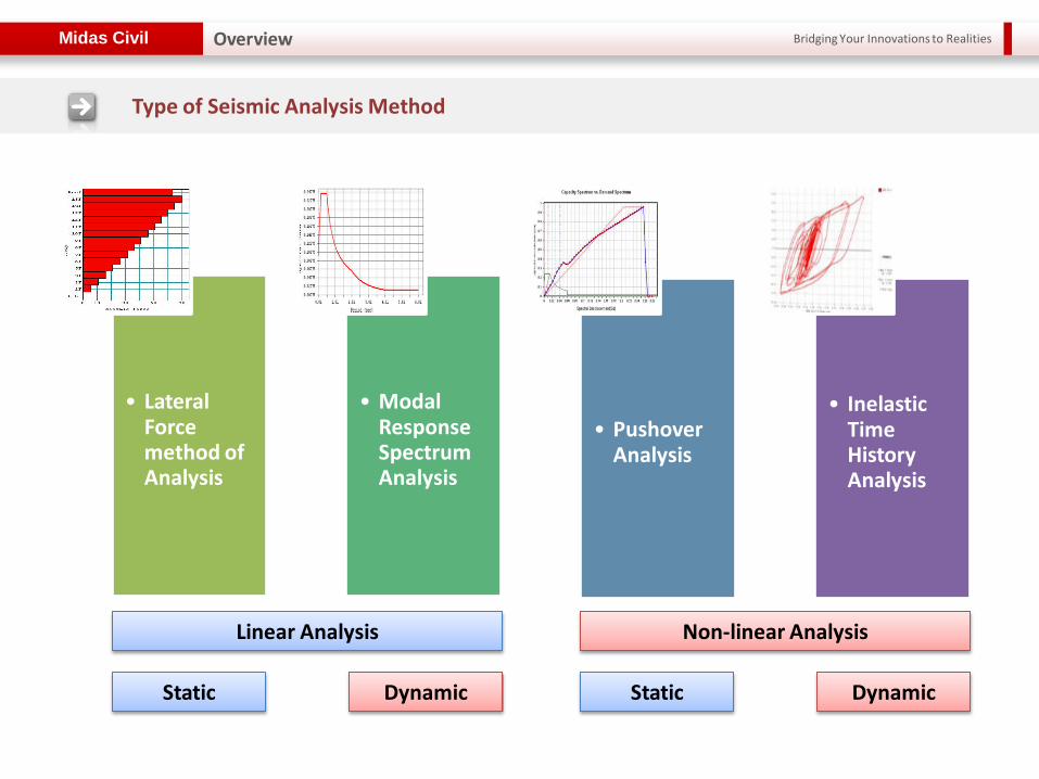
• Lateral Force method of Analysis
• Modal Response Spectrum Analysis
• Pushover Analysis
• Inelastic Time History Analysis
Overview
Type of Seismic Analysis Method
Linear Analysis Non-linear Analysis
Static Dynamic Static Dynamic
Bridging Your Innovations to Realities Midas Civil
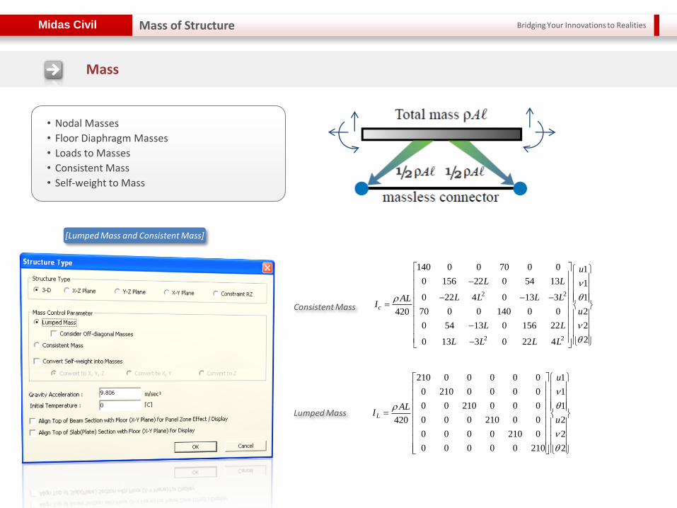
Mass
• Nodal Masses
• Floor Diaphragm Masses
• Loads to Masses
• Consistent Mass
• Self-weight to Mass
[Lumped Mass and Consistent Mass]
Lumped Mass
Consistent Mass
Mass of Structure
210 0 0 0 0 0 1
0 210 0 0 0 0 1
0 0 210 0 0 0 1
0 0 0 210 0 0 2420
0 0 0 0 210 0 2
0 0 0 0 0 210 2
L
u
ALI
u
2 2
2 2
140 0 0 70 0 0 1
0 156 22 0 54 13 1
0 22 4 0 13 3 1
70 0 0 140 0 0 2420
0 54 13 0 156 22 2
20 13 3 0 22 4
c
u
L L
L L L LALI
u
L L
L L L L
ν1 ν2
u1 u2
θ1 θ2
1 2
Bridging Your Innovations to Realities Midas Civil
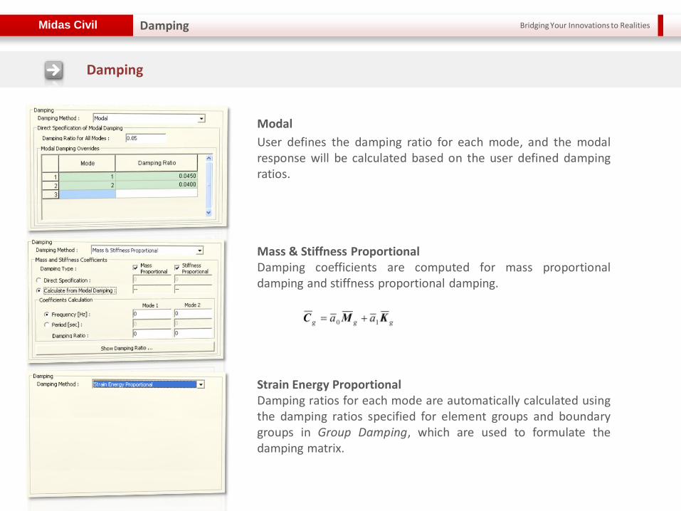
Damping
Modal
User defines the damping ratio for each mode, and the modal response will be calculated based on the user defined damping ratios.
Mass & Stiffness Proportional Damping coefficients are computed for mass proportional damping and stiffness proportional damping.
Strain Energy Proportional Damping ratios for each mode are automatically calculated using the damping ratios specified for element groups and boundary groups in Group Damping, which are used to formulate the damping matrix.
Damping
Bridging Your Innovations to Realities Midas Civil
Modal Analysis
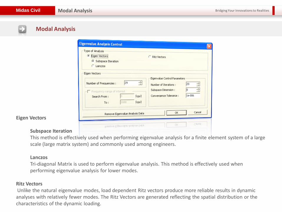
Modal Analysis
Eigen Vectors
Subspace Iteration This method is effectively used when performing eigenvalue analysis for a finite element system of a large scale (large matrix system) and commonly used among engineers.
Lanczos Tri-diagonal Matrix is used to perform eigenvalue analysis. This method is effectively used when performing eigenvalue analysis for lower modes.
Ritz Vectors Unlike the natural eigenvalue modes, load dependent Ritz vectors produce more reliable results in dynamic analyses with relatively fewer modes. The Ritz Vectors are generated reflecting the spatial distribution or the characteristics of the dynamic loading.

Bridging Your Innovations to Realities Midas Civil Modal Analysis
Construction Stage Analysis Control for Structural Stiffness in Post CS
The member forces of the last step of the last construction stage in a construction stage analysis
are converted into Initial Force for Geometric Stiffness to reflect the forces into the geometric stiffness of the structure at the post construction (Post CS) stage.
Load > Initial Forces > Small Displacement
> Initial Element Forces(CS)
Bridging Your Innovations to Realities Midas Civil
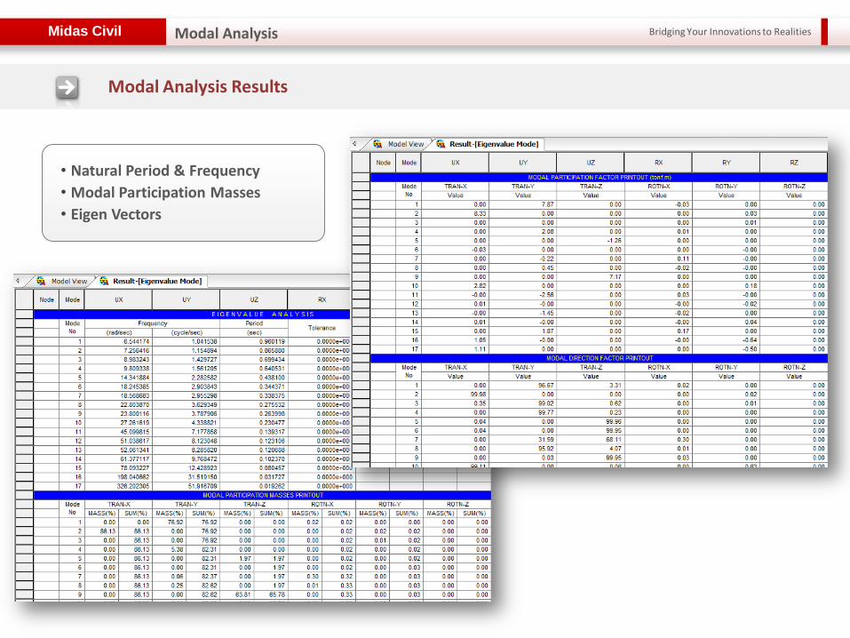
Modal Analysis Results
Modal Analysis
• Natural Period & Frequency
• Modal Participation Masses
• Eigen Vectors
Bridging Your Innovations to Realities Midas Civil
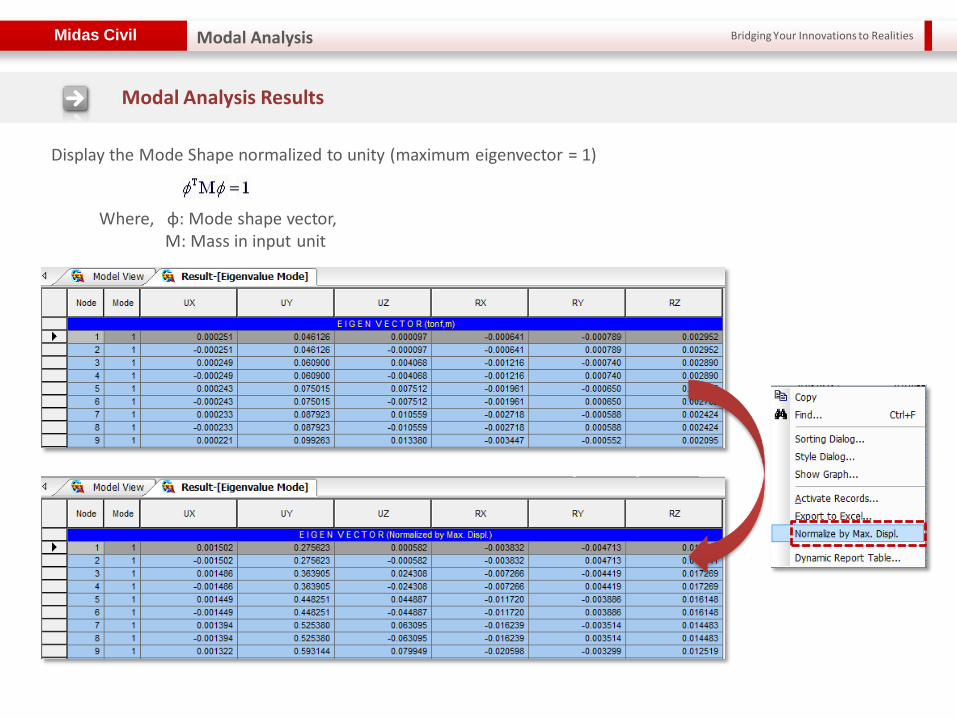
Modal Analysis Results
Modal Analysis
Display the Mode Shape normalized to unity (maximum eigenvector = 1)
Where, φ: Mode shape vector, M: Mass in input unit

Bridging Your Innovations to Realities Midas Civil
Implemented RS functions
such as IBC 2000, Eurocode8, NBC, Canada, China, Taiwan, India..etc.
IBC 2012 & 2009 will be available in the new version (2012 June).
Excitation Angle for considering the major axis of the structure
Various Damping Method
(Model, Mass & Stiffness Proportional, Strain Energy Proportional)
Response Spectrum Function & Cases
Response Spectrum Analysis
Bridging Your Innovations to Realities Midas Civil
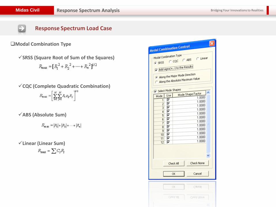
SRSS (Square Root of Sum of the Squares)
CQC (Complete Quadratic Combination)
ABS (Absolute Sum)
Linear (Linear Sum)
Modal Combination Type
Response Spectrum Load Case
Response Spectrum Analysis
Bridging Your Innovations to Realities Midas Civil
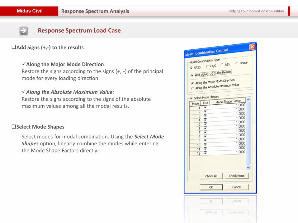
Along the Major Mode Direction: Restore the signs according to the signs (+, -) of the principal mode for every loading direction. Along the Absolute Maximum Value: Restore the signs according to the signs of the absolute maximum values among all the modal results.
Response Spectrum Load Case
Response Spectrum Analysis
Add Signs (+,-) to the results
Select Mode Shapes
Select modes for modal combination. Using the Select Mode Shapes option, linearly combine the modes while entering the Mode Shape Factors directly.
Bridging Your Innovations to Realities Midas Civil Response Spectrum Analysis
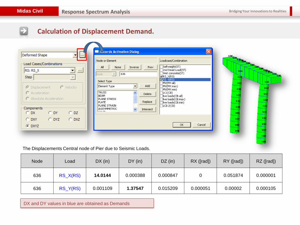
Calculation of Displacement Demand.
The Displacements Central node of Pier due to Seismic Loads.
Node Load DX (in) DY (in) DZ (in) RX ([rad]) RY ([rad]) RZ ([rad])
636 RS_X(RS) 14.0144 0.000388 0.000847 0 0.051874 0.000001
636 RS_Y(RS) 0.001109 1.37547 0.015209 0.000051 0.00002 0.000105
DX and DY values in blue are obtained as Demands
Bridging Your Innovations to Realities Midas Civil
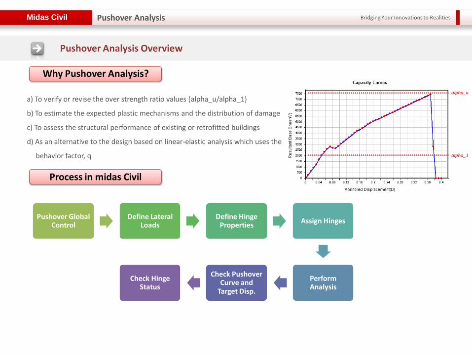
Why Pushover Analysis?
a) To verify or revise the over strength ratio values (alpha_u/alpha_1)
b) To estimate the expected plastic mechanisms and the distribution of damage
c) To assess the structural performance of existing or retrofitted buildings
d) As an alternative to the design based on linear-elastic analysis which uses the
behavior factor, q
Pushover Global Control
Define Lateral Loads
Define Hinge Properties
Assign Hinges
Perform Analysis
Check Pushover Curve and
Target Disp.
Check Hinge Status
Process in midas Civil
alpha_u
alpha_1
Pushover Analysis Overview
Pushover Analysis
Bridging Your Innovations to Realities Midas Civil
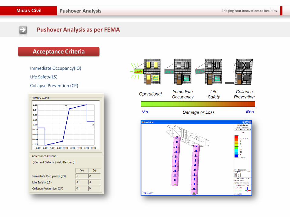
Acceptance Criteria
Immediate Occupancy(IO)
Life Safety(LS)
Collapse Prevention (CP)
Pushover Analysis as per FEMA
Pushover Analysis

Bridging Your Innovations to Realities Midas Civil
Pushover Global Control
Pushover Analysis
• Initial Load: Enter the initial load (in general, the gravity loads) for pushover analysis.
• Convergence Criteria: Specify the maximum number of (iterations) sub-iterations and a tolerance limit for convergence criterion.
• Stiffness Reduction Ratio: Specify stiffness reduction ratios after the 1st and 2nd yielding points (1st yielding for bilinear curve, 1st and 2nd yielding for trilinear curve) relative to the elastic stiffness.
• Reference location for distributed hinges: Specify the reference location for calculating yield strength of beam elements which distributed hinge is assigned.
Bridging Your Innovations to Realities Midas Civil
Load
Pushover Analysis
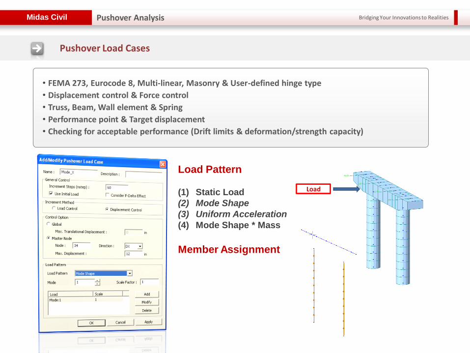
Pushover Load Cases
• FEMA 273, Eurocode 8, Multi-linear, Masonry & User-defined hinge type
• Displacement control & Force control
• Truss, Beam, Wall element & Spring
• Performance point & Target displacement
• Checking for acceptable performance (Drift limits & deformation/strength capacity)
Load Pattern
(1) Static Load
(2) Mode Shape
(3) Uniform Acceleration
(4) Mode Shape * Mass
Member Assignment
Bridging Your Innovations to Realities Midas Civil
Pushover Analysis
Pushover Analysis
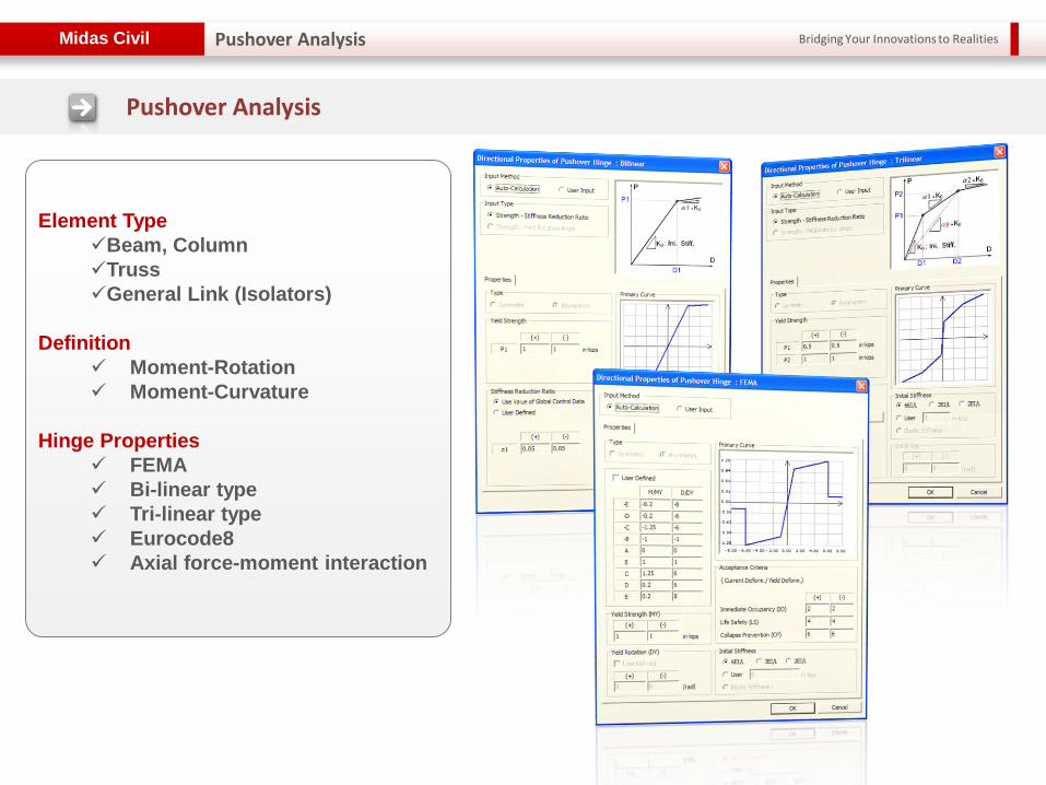
Element Type
Beam, Column
Truss
General Link (Isolators)
Definition
Moment-Rotation
Moment-Curvature
Hinge Properties
FEMA
Bi-linear type
Tri-linear type
Eurocode8
Axial force-moment interaction
Bridging Your Innovations to Realities Midas Civil
Pushover Curve
Pushover Analysis
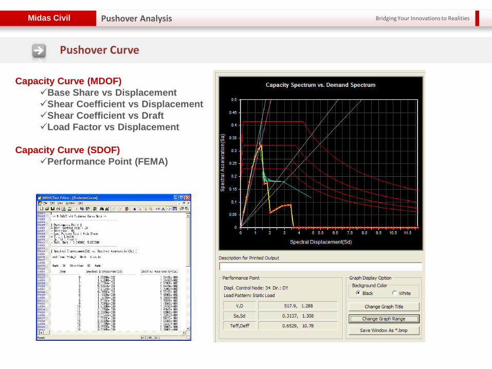
Capacity Curve (MDOF)
Base Share vs Displacement
Shear Coefficient vs Displacement
Shear Coefficient vs Draft
Load Factor vs Displacement
Capacity Curve (SDOF)
Performance Point (FEMA)
Bridging Your Innovations to Realities Midas Civil
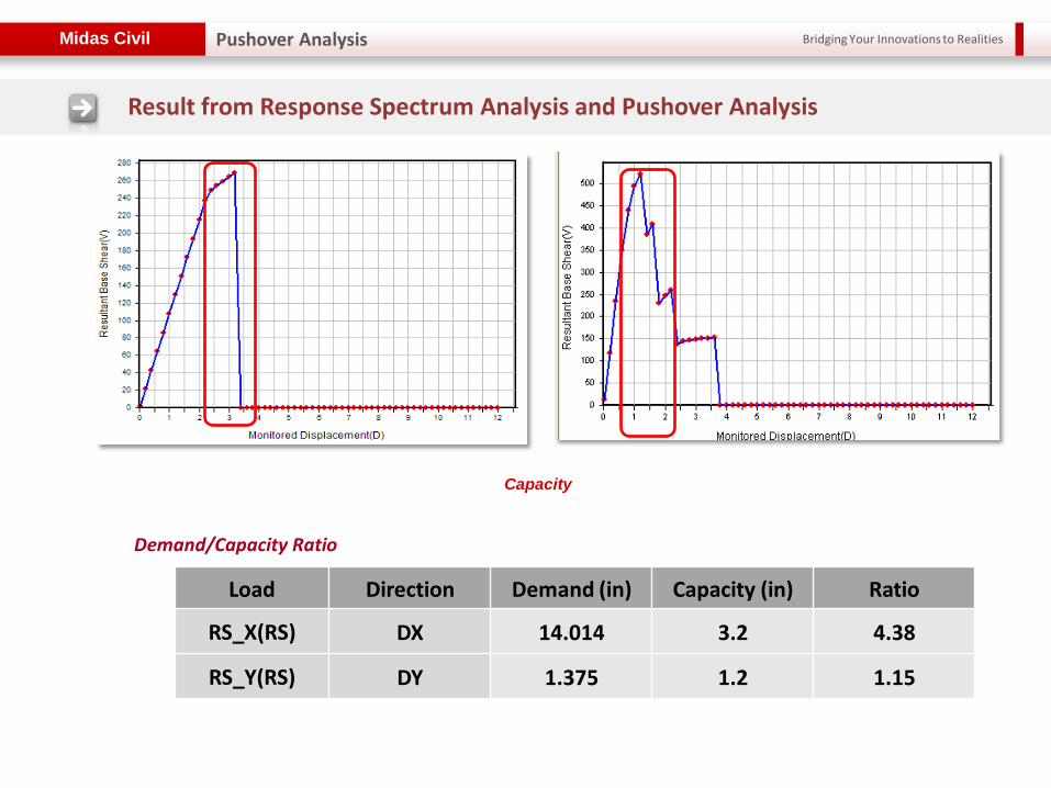
Load Direction Demand (in) Capacity (in) Ratio
RS_X(RS) DX 14.014 3.2 4.38
RS_Y(RS) DY 1.375 1.2 1.15
Demand/Capacity Ratio
Result from Response Spectrum Analysis and Pushover Analysis
Capacity
Pushover Analysis

Bridging Your Innovations to Realities Midas Civil
Time History Analysis Overview
Time History Analysis
Enter Mass Data Define Eigen value
Analysis Control Enter Inelastic Hinges
or General Links
Time Forcing Function Time History Load
Cases (optional)Time
Varying Static Load
-Dynamic Nodal Load -Ground Acceleration
-Multiple Support Excitation
Perform Analysis Verify Analysis Results
Process in midas Civil
Bridging Your Innovations to Realities Midas Civil
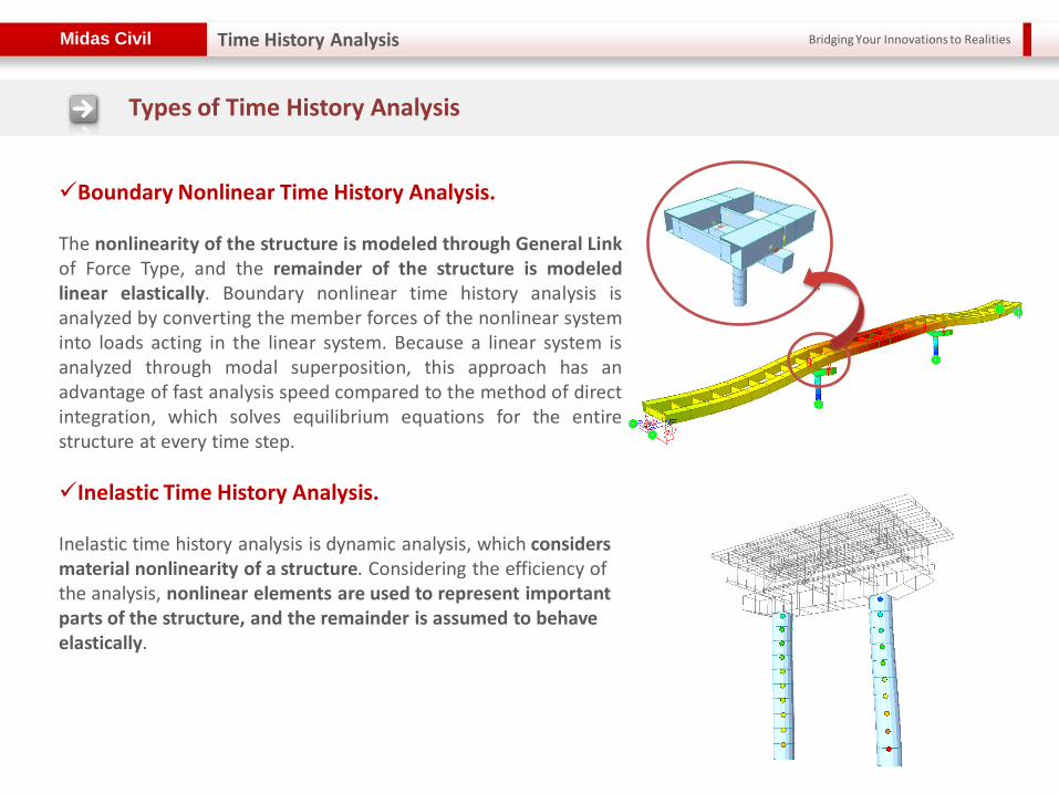
Boundary Nonlinear Time History Analysis. The nonlinearity of the structure is modeled through General Link of Force Type, and the remainder of the structure is modeled linear elastically. Boundary nonlinear time history analysis is analyzed by converting the member forces of the nonlinear system into loads acting in the linear system. Because a linear system is analyzed through modal superposition, this approach has an advantage of fast analysis speed compared to the method of direct integration, which solves equilibrium equations for the entire structure at every time step.
Inelastic Time History Analysis. Inelastic time history analysis is dynamic analysis, which considers material nonlinearity of a structure. Considering the efficiency of the analysis, nonlinear elements are used to represent important parts of the structure, and the remainder is assumed to behave elastically.
Types of Time History Analysis
Time History Analysis
Bridging Your Innovations to Realities Midas Civil
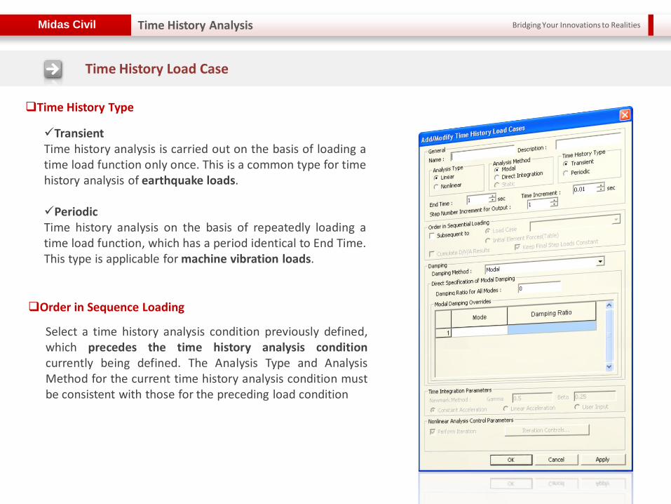
Transient Time history analysis is carried out on the basis of loading a time load function only once. This is a common type for time history analysis of earthquake loads. Periodic Time history analysis on the basis of repeatedly loading a time load function, which has a period identical to End Time. This type is applicable for machine vibration loads.
Select a time history analysis condition previously defined, which precedes the time history analysis condition currently being defined. The Analysis Type and Analysis Method for the current time history analysis condition must be consistent with those for the preceding load condition
Time History Type
Order in Sequence Loading
Time History Load Case
Time History Analysis
Bridging Your Innovations to Realities Midas Civil
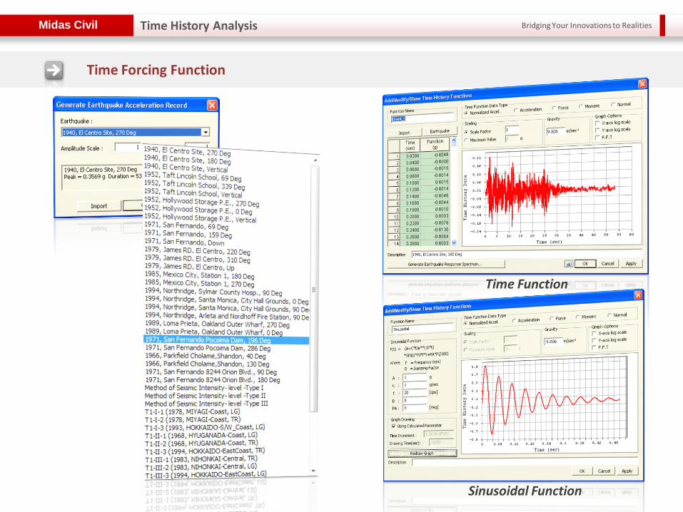
Time Function
Time Forcing Function
Time History Analysis
Sinusoidal Function
Bridging Your Innovations to Realities Midas Civil
Ground Acceleration & Dynamic Nodal Load
Time History Analysis
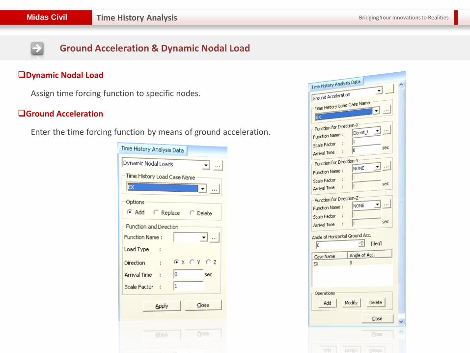
Assign time forcing function to specific nodes.
Dynamic Nodal Load
Enter the time forcing function by means of ground acceleration.
Ground Acceleration

Bridging Your Innovations to Realities Midas Civil
Define a dynamic load case by multiplying static load cases already entered by time functions, which should be defined as a Normal type in the "Time Forcing Functions". This function is used to reflect the effect of the self-weight in the time history analysis due to seismic loads.
Time Varying Static Load
Time History Analysis
Define self weight as a static load
Define time forcing function for self weigh
Make a link between the static load case, time history load case, and time forcing function in Time Varying Static Load
Select the pre-defined time history load case as an “Sequential Loading” in Time History Load Case

Bridging Your Innovations to Realities Midas Civil
Base Isolators and Dampers
Objectives of Seismic Isolation Systems
Enhance performance of structures at all hazard levels by:
Minimizing interruption of use of facility
Reducing damaging deformations in structural and nonstructural components
Reducing acceleration response to minimize contents related damage
Characteristics of Well-Designed Seismic Isolation Systems
Flexibility to increase period of vibration and thus reduce force response
Energy dissipation to control the isolation system displacement
Rigidity under low load levels such as wind and minor earthquakes
Time History Analysis
Bridging Your Innovations to Realities Midas Civil Time History Analysis
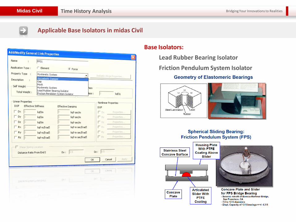
Base Isolators:
Lead Rubber Bearing Isolator
Friction Pendulum System Isolator
Applicable Base Isolators in midas Civil
Bridging Your Innovations to Realities Midas Civil
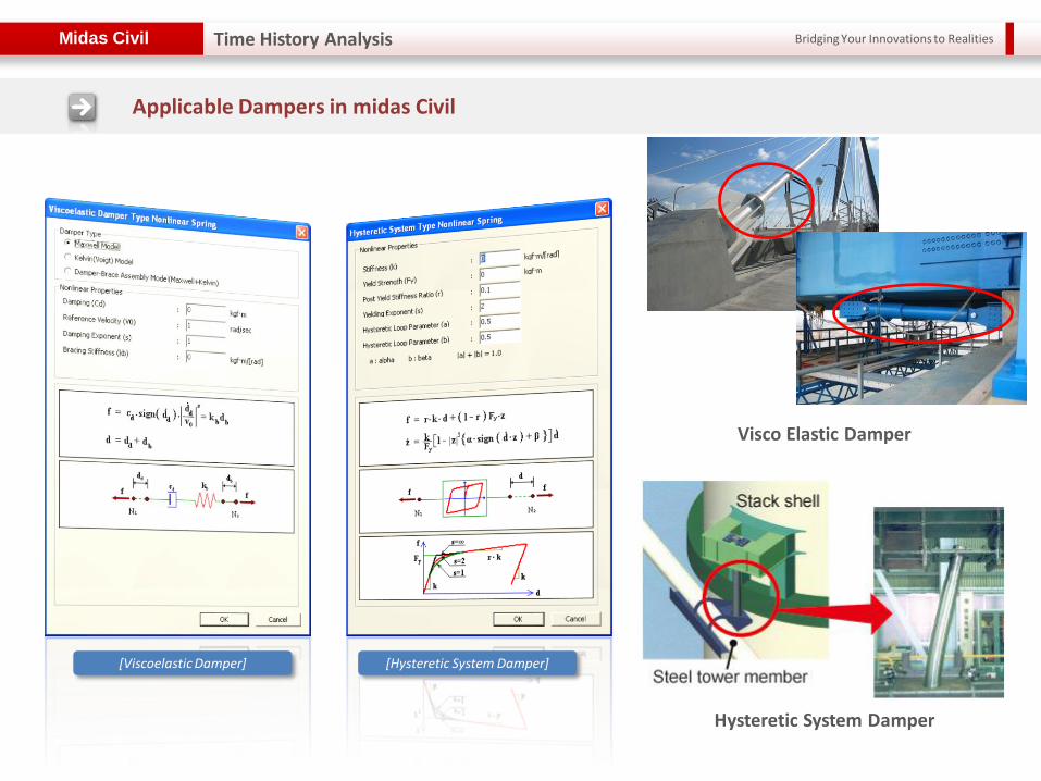
[Viscoelastic Damper] [Hysteretic System Damper]
Applicable Dampers in midas Civil
Visco Elastic Damper
Hysteretic System Damper
Time History Analysis
Bridging Your Innovations to Realities Midas Civil
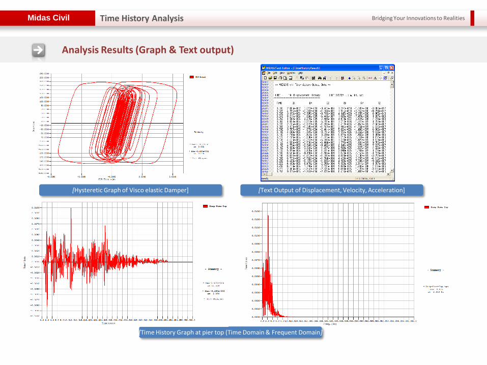
Analysis Results (Graph & Text output)
[Hysteretic Graph of Visco elastic Damper]
[Time History Graph at pier top (Time Domain & Frequent Domain]
[Time History Text Output]
[Text Output of Displacement, Velocity, Acceleration]
Time History Analysis

Bridging Your Innovations to Realities Midas Civil
Inelastic Time History Analysis
Time History Analysis
Hysteresis Curve (Rz-Mz) [Ductility Factor] [Status of Yielding]
Inelastic Hinge
Ground Acceleration
Inelastic Time History Analysis of Extradosed Bridge

Bridging Your Innovations to Realities Midas Civil
Arrival time : t = 0 sec
Arrival time, : t = 2 seconds
Ground Acceleration
Multiple Support Excitation
Time History Analysis

Bridging Your Innovations to Realities Midas Civil
General Spring Support with 6x6 Coupled Matrix for Damping and Mass
Time History Analysis

Bridging Your Innovations to Realities Midas Civil Time History Analysis
Multi-Linear Kinematic and Takeda Hinge Model
Takeda Hinge Model
Kinematic Hinge Model

Bridging Your Innovations to Realities
Thank You! Thank You!