bridgelux gen 7 v13 thrive array - farnell
TRANSCRIPT

1
BXRE-27S|30S|35S|40S|50S|57S|65S
Bridgelux® Gen 7 V13 Thrive™ Array Product Data Sheet DS321

Introduction
Bridgelux Thrive™ combines unique chip, phosphor and packaging technology to closely match the spectra of natural
light over the visible wavelength range. Thrive can be used in constant color point luminaires to bring full spectrum
natural light indoors or in tunable white luminaires to incorporate circadian elements that may impact human well-being.
The high fidelity spectral output of Thrive creates stunning environments with excellent color rendering and outstanding
TM30 metrics. Thrive is available in both SMD components and LED arrays to enable a broad range of lighting
applications including retail, hospitality, office, education, architectural, museums, healthcare and residential lighting.
Features
• Engineered spectrum to closely match natural light
• CRI >95, R1-R15 >90, high Rf and Rg values
• High efficacy full spectrum solution
• No violet chip augmentation
• Hot color targeted
• Form factor consistent with existing Bridgelux COB arrays
• Broad product platform availability (SMDs and COBs)
Benefits
• Full consistent spectrum with fewer spectral spikes
• Natural and vivid color rendering
• Greater energy savings, lower utility costs
• Economical, high efficiency solution
• Uniform and consistent white light at application conditions
• Ease of design and rapid go-to-market
• Enables greater design flexibility and platform color consistency
V13
Thr
ive

1
Contents
Product Feature Map 2
Product Nomenclature 2
Product Selection Guide 3
Spectrum Characteristics 5
Electrical Characteristics 8
Absolute Maximum Ratings 9
Eye Safety 10
Product Bin Definitions 11
Performance Curves 12
Typical Radiation Pattern 13
Mechanical Dimensions 14
Packaging and Labeling 15
Design Resources 17
Precautions 17
Disclaimers 17
About Bridgelux 18
2
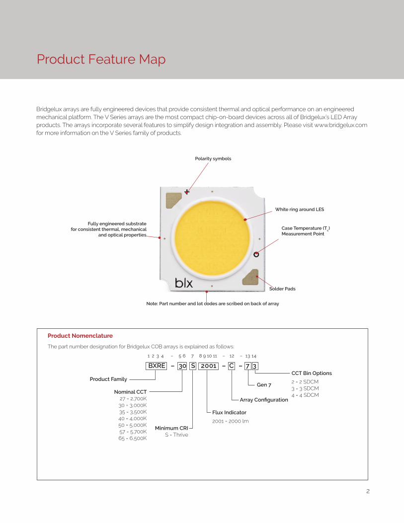
Product Feature Map
Product Nomenclature
The part number designation for Bridgelux COB arrays is explained as follows:
Bridgelux arrays are fully engineered devices that provide consistent thermal and optical performance on an engineered mechanical platform. The V Series arrays are the most compact chip-on-board devices across all of Bridgelux’s LED Array products. The arrays incorporate several features to simplify design integration and assembly. Please visit www.bridgelux.com for more information on the V Series family of products.
Polarity symbols
Fully engineered substrate for consistent thermal, mechanical
and optical properties
Note: Part number and lot codes are scribed on back of array
Solder Pads
Case Temperature (Tc) Measurement Point
White ring around LES
BXRE – 30 S 2001 – C – 7 3
1 2 3 4 – 5 6 7 8 9 10 11 – 12 – 13 14
Product FamilyCCT Bin Options
2 = 2 SDCM3 = 3 SDCM4 = 4 SDCM
Flux Indicator
2001 = 2000 lmMinimum CRI
S = Thrive
Array Configuration
Nominal CCT27 = 2,700K30 = 3,000K35 = 3,500K40 = 4,000K50 = 5,000K57 = 5,700K65 = 6,500K
Gen 7

3
Product Selection Guide
The following product configurations are available:
Table 1: Selection Guide, Pulsed Measurement Data (Tc= 25°C)
Part Number1,6
Nominal CCT1
(K)CRI2
Nominal Drive
Current3 (mA)
Typical Vf (V)
Typical Pulsed Flux4,5,6,7
Tc = 25ºC(lm)
Minimum Pulsed Flux6,7,8
Tc = 25ºC(lm)
Typical Power
(W)
Typical Efficacy (lm/W)
TypicalPhotosynthetic
Photon Flux (PPF)
Typical Photon
Efficiency(µmol/J)
BXRE-27S2001-C-73 2700 95 630 34.4 2330 2050 21.7 108 40.66 2.06
BXRE-30S2001-C-73 3000 95 630 34.4 2520 2218 21.7 116 43.05 2.16
BXRE-35S2001-C-73 3500 95 630 34.4 2612 2299 21.7 121 43.23 2.15
BXRE-40S2001-C-73 4000 95 630 34.4 2661 2342 21.7 123 43.31 2.14
BXRE-50S2001-C-74 5000 95 630 34.4 2774 2441 21.7 128 45.47 2.22
BXRE-57S2001-C-74 5700 95 630 34.4 2810 2473 21.7 130 46.20 2.24
BXRE-65S2001-C-74 6500 95 630 34.4 2782 2448 21.7 128 45.74 2.22
Table 2: Selection Guide, Stabilized DC Test Performance (Tc= 85°C)4,5,6
Part Number1,6
Nominal CCT1
(K)CRI2
Nominal Drive
Current3 (mA)
Typical Vf (V)
Typical DC Flux4,5,6,7
Tc = 85ºC(lm)
Minimum DC
Flux6,7,8,9
Tc = 85ºC(lm)
Typical Power
(W)
Typical Efficacy (lm/W)
TypicalPhotosynthetic
Photon Flux (PPF)
Typical Photon
Efficiency(µmol/J)
BXRE-27S2001-C-73 2700 95 630 33.7 2120 1866 21.2 100 36.99 1.91
BXRE-30S2001-C-73 3000 95 630 33.7 2293 2018 21.2 108 39.18 2.01
BXRE-35S2001-C-73 3500 95 630 33.7 2377 2092 21.2 112 39.34 2.00
BXRE-40S2001-C-73 4000 95 630 33.7 2421 2131 21.2 114 39.40 1.99
BXRE-50S2001-C-74 5000 95 630 33.7 2524 2221 21.2 119 41.67 2.08
BXRE-57S2001-C-74 5700 95 630 33.7 2557 2250 21.2 120 42.04 2.09
BXRE-65S2001-C-74 6500 95 630 33.7 2532 2228 21.2 119 41.63 2.06
Notes for Table 1 & 2:1. Product CCT is hot targeted at Tj= 85°C. Nominal CCT as defined by ANSI C78.377-2011.2. All CRI values are measured at Tj = Tc = 25°C. CRI values are minimums. Bridgelux maintains a ± 3 tolerance on CRI values. 3. Drive current is referred to as nominal drive current. 4. Products tested under pulsed condition (10ms pulse width) at nominal test current where Tj (junction temperature) = Tc (case temperature) = 25°C. Typical stabilized DC
performance values are provided as reference only and are not a guarantee of performance. 5. Typical performance values are provided as a reference only and are not a guarantee of performance.6. Typical performance is estimated based on operation under DC (direct current) with LED array mounted onto a heat sink with thermal interface
material and the case temperature maintained at 85°C. Based on Bridgelux test setup, values may vary depending on the thermal design of the luminaire and/or the exposed environment to which the product is subjected.
7. Bridgelux maintains a ±7% tolerance on flux measurements. 8. Minimum flux values at the nominal test current are guaranteed by 100% test. 9. Minimum flux values at elevated temperatures are provided for reference only and are not guaranteed by 100% production testing. Based on Bridgelux test setup,
values may vary depending on the thermal design of the luminaire and/or the exposed environment to which the product is subjected.

4
Performance at Commonly Used Drive Currents
V Series Thrive LED arrays are tested to the specifications shown using the nominal drive currents in Table 1. V Series
Thrive LED Arrays may also be driven at other drive currents dependent on specific application design requirements. The
performance at any drive current can be derived from the current vs. voltage characteristics shown in Figure 10 and the
flux vs. current characteristics shown in Figure 11. The performance at commonly used drive currents is summarized in
Table 3.
Table 3: Product Performance at Commonly Used Drive Currents
Part Number CRIDrive
Current1
(mA)
Typical Vf Tc = 25ºC
(V)
Typical Power
Tc = 25ºC(W)
Typical Flux2
Tc = 25ºC(lm)
Typical DC Flux3 Tc = 85ºC
(lm)
Typical Efficacy Tc = 25ºC(lm/W)
BXRE-27S2001-C-73 95
315 32.2 10.1 1202 1117 119
420 33.6 14.1 1600 1464 113
630 34.4 21.7 2330 2120 108
945 35.2 33.3 3329 3017 100
1260 35.7 45.0 4332 3815 96
BXRE-30S2001-C-73 95
315 32.2 10.1 1301 1208 128
420 33.6 14.1 1730 1583 123
630 34.4 21.7 2520 2293 116
945 35.2 33.3 3601 3263 108
1260 35.7 45.0 4685 4126 104
BXRE-35S2001-C-73 95
315 32.2 10.1 1348 1252 133
420 33.6 14.1 1793 1641 127
630 34.4 21.7 2612 2377 121
945 35.2 33.3 3732 3382 112
1260 35.7 45.0 4857 4276 108
BXRE-40S2001-C-73 95
315 32.2 10.1 1373 1275 135
420 33.6 14.1 1827 1672 129
630 34.4 21.7 2661 2421 123
945 35.2 33.3 3802 3446 114
1260 35.7 45.0 4947 4356 110
BXRE-50S2001-C-73 95
315 32.2 10.1 1432 1329 141
420 33.6 14.1 1905 1743 135
630 34.4 21.7 2774 2524 128
945 35.2 33.3 3964 3592 119
1260 35.7 45.0 5158 4542 115
BXRE-57S2001-C-73 95
315 32.2 10.1 1450 1347 143
420 33.6 14.1 1929 1765 137
630 34.4 21.7 2810 2557 130
945 35.2 33.3 4015 3639 121
1260 35.7 45.0 5224 4600 116
BXRE-65S2001-C-73 95
315 32.2 10.1 1436 1333 142
420 33.6 14.1 1910 1748 135
630 34.4 21.7 2782 2532 128
945 35.2 33.3 3975 3603 120
1260 35.7 45.0 5173 4555 115
Notes for Table 3:1. Alternate drive currents are provided for reference only and are not a guarantee of performance.2. Bridgelux maintains a ± 7% tolerance on flux measurements.3. Typical stabilized DC performance values are provided as reference only and are not a guarantee of performance.

5
Spectrum Characteristics
Table 4: Typical Color Rendering Index and TM-30 Values at, Tc=85°C
Nominal CCT1
Rf Rg R1 R2 R3 R4 R5 R6 R7 R8 R9 R10 R11 R12 R13 R14 R15
2700K 95 103 97 99 94 94 97 98 97 98 99 97 91 98 98 95 98
3000K 95 104 98 99 93 94 97 98 96 96 97 96 92 95 98 95 97
3500K 95 98 98 98 97 98 98 98 98 97 93 97 97 95 98 97 98
4000K 97 100 99 99 97 99 99 99 99 98 94 97 99 96 99 98 98
5000K 97 100 98 99 98 98 98 98 99 98 95 98 98 98 98 98 97
5700K 94 98 98 98 97 95 98 97 96 95 92 97 96 96 98 98 97
6500K 95 98 98 98 97 96 98 98 96 96 93 97 96 97 98 98 97
Note for Table 4:
1. Bridgelux maintains a tolerance of ± 3 on Color Rendering Index R1-R15 measurements and TM-30 measurements.
Figure 1: 2700K Thrive TM-30 Graphs
Figure 2: 3000K Thrive TM-30 Graphs
Figure 3: 3500K Thrive TM-30 Graphs

6
Spectrum Characteristics
Figure 4: 4000K Thrive TM-30 Graphs
Figure 5: 5000K Thrive TM-30 Graphs
Figure 6: 5700K Thrive TM30 Graphs
Figure 7: 6500K Thrive TM-30 Graphs

7
Figure 8: Typical Color Spectrum
Note for Figure 8:
1. Color spectra measured at nominal current for Tj = 85°C.
Spectral Matching to Natural LightThe lighting market is in the early stages of adoption of human-centric lighting (HCL). HCL encompasses the effects of lighting on the physical and emotional
health and well-being of people. Throughout evolution, the human visual system has evolved under the natural light of sun and fire. These light sources have
standardized industry spectral power definitions that describe the state of natural light. However, conventional metrics such as CCT, CRI, and TM-30 fail to
adequately quantify the naturalness, or closeness of these light sources to the standardized natural spectra. Due to a lack of an industry standard metric to
quantitatively measure the naturalness of a light source, Bridgelux has pioneered a new metric that takes the guesswork out of comparing LED light sources
to natural light.
Average Spectral Difference, or ASD, is calculated by measuring the absolute difference between two spectra at discrete wavelengths. These values are aver-aged across a wavelength range derived from the photopic response curve, or V(λ); a luminous efficiency function describing the average spectral sensitivity
of human perception of brightness. The range of 425nm to 690nm was selected to remove the tails of the V(λ) gaussian distribution below 1% of the peak value
at 555nm, covering 99.9% of the area under the photopic response curve. Natural light is defined following the approach of IES TM-30; black body curves for
light sources of ≤4000K and the CIE standard illuminant D for light sources of ≥ 5000K.
Natural light has an ASD of 0%; lower ASD values indicate a closer match to natural light. Thrive is engineered to provide the closest match to natural light
available using proprietary chip, phosphor and packaging technology, resulting in an ASD between 8% to 10% for all CCTs. By comparison, standard 80, 90,
and 98 CRI light sources have ASD values that are 100% to 300% larger than Thrive. To learn more about the ASD metric, please contact your Bridgelux sales
representative. Bridgelux will publish a white paper to further educate the market about the benefits of the ASD metric in Q2 2020.
Spectrum Characteristics
0%
20%
40%
60%
80%
100%
350 400 450 500 550 600 650 700 750 800
Re
lati
ve R
adia
nt
Po
we
r(%
)
Wavelength(nm)
2700K
3000K
3500K
4000K
0%
20%
40%
60%
80%
100%
350 400 450 500 550 600 650 700 750 800R
ela
tive
Rad
ian
t P
ow
er(
%)
Wavelength(nm)
5000K5700K6500K

8
Electrical Characteristics
Table 5: Electrical Characteristics
Part NumberDrive Current
(mA)
Forward VoltagePulsed, Tc = 25ºC (V) 1, 2, 3, 8 Typical
Coefficient of Forward
Voltage4 ∆Vf/∆Tc
(mV/ºC)
Typical Thermal
Resistance Junction to Case5,6
Rj-c (ºC/W)
Driver Selection Voltages7
(V)
Minimum Typical MaximumVf Min.
Hot Tc = 105ºC
(V)
Vf Max. Cold
Tc = -40ºC (V)
BXRE-xxx2001-C-7x630 32.2 34.4 37.4 -14.1 0.20 31.0 38.3
1260 33.4 35.7 38.8 -14.1 0.24 33.4 41.0
Notes for Table 5:
1. Parts are tested in pulsed conditions, Tc = 25°C. Pulse width is 10ms.
2. Voltage minimum and maximum are provided for reference only and are not a guarantee of performance.
3. Bridgelux maintains a tester tolerance of ± 0.10V on forward voltage measurements.
4. Typical coefficient of forward voltage tolerance is ± 0.1mV for nominal current.
5. Thermal resistance values are based from test data of a 3000K 80 CRI product.
6. Thermal resistance value was calculated using total electrical input power; optical power was not subtracted from input power. The thermal interface
material used during testing is not included in the thermal resistance value.
7. Vf min hot and max cold values are provided as reference only and are not guaranteed by test. These values are provided to aid in driver design and
selection over the operating range of the product.
8. This product has been designed and manufactured per IEC 62031:2014. This product has passed dielectric withstand voltage testing at 1160 V. The working
voltage designated for the insulation is 80V d.c. The maximum allowable voltage across the array must be determined in the end product application.

9
Absolute Maximum Ratings
Table 6: Maximum Ratings
Parameter Maximum Rating
LED Junction Temperature (Tj) 150°C
Storage Temperature -40°C to +105°C
Operating Case Temperature1 (Tc) 105°C
Soldering Temperature2 300°C or lower for a maximum of 6 seconds
Maximum Drive Current3 1260mA
Maximum Peak Pulsed Drive Current4 1800mA
Maximum Reverse Voltage5 -60V
Notes for Table 6:
1. For IEC 62717 requirement, please consult your Bridgelux sales representative.
2. Refer to Bridgelux Application Note AN101: Handling and Assembly of Bridgelux V Series LED Arrays.
3. Arrays may be driven at higher currents however lumen maintenance may be reduced.
4. Bridgelux recommends a maximum duty cycle of 10% and pulse width of 20 ms when operating LED Arrays at maximum peak pulsed current specified. Maximum peak pulsed currents indicate values where LED Arrays can be driven without catastrophic failures.
5. Light emitting diodes are not designed to be driven in reverse voltage and will not produce light under this condition. Maximum rating provided for reference only.
10
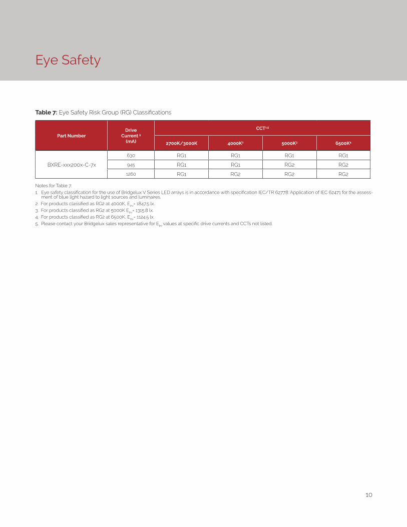
Table 7: Eye Safety Risk Group (RG) Classifications
Part NumberDrive
Current 5
(mA)
CCT1,5
2700K/3000K 4000K2 5000K3 6500K4
BXRE-xxx200x-C-7x
630 RG1 RG1 RG1 RG1
945 RG1 RG1 RG2 RG2
1260 RG1 RG2 RG2 RG2
Notes for Table 7:1. Eye safety classification for the use of Bridgelux V Series LED arrays is in accordance with specification IEC/TR 62778: Application of IEC 62471 for the assess-
ment of blue light hazard to light sources and luminaires.2. For products classified as RG2 at 4000K, Ethr= 1847.5 lx.3. For products classified as RG2 at 5000K Ethr= 1315.8 lx.4. For products classified as RG2 at 6500K, Ethr= 1124.5 lx.5. Please contact your Bridgelux sales representative for Ethr values at specific drive currents and CCTs not listed.
Eye Safety

11
Product Bin Definitions
Table 8: 2-, 3- and 4-step MacAdam Ellipse Color Bin Definitions
CCT
Center Point Degree 2-step 3-step 4-step
x y λ(°) a b a b a b
2700K 0.4578 0.4101 53.700 0.00540 0.00280 0.0081 0.0042 N/A N/A
3000K 0.4338 0.403 53.217 0.00556 0.00272 0.0083 0.0041 N/A N/A
4000K 0.3818 0.3797 53.717 0.00626 0.00268 0.0094 0.0040 N/A N/A
5000K 0.3447 0.3553 59.617 N/A N/A 0.0082 0.0035 0.0110 0.0047
5700K 0.3287 0.3417 59.060 N/A N/A 0.0074 0.0032 0.0099 0.0042
6500K 0.3123 0.3282 58.567 N/A N/A 0.0066 0.0028 0.0090 0.0038
Notes for Table 8:
1. Color binning at Tc=85°C
2. Bridgelux maintains a tolerance of ± 0.007 on x and y color coordinates in the CIE 1931 color space.
Figure 9: C.I.E. 1931 Chromaticity Diagram (Color targeted at Tc=85°C)
0.34
0.36
0.38
0.4
0.42
0.44
0.36 0.39 0.42 0.45 0.48
Y
X
3 SDCM
2 SDCM
3500K
2700K
3000K
4000K
0.3
0.31
0.32
0.33
0.34
0.35
0.36
0.37
0.38
0.39
0.3 0.31 0.32 0.33 0.34 0.35 0.36 0.37
Y
X
4 SDCM
3 SDCM
6500K
5700K
5000K

12
Performance Curves
Figure 10: V13C Drive Current vs. Voltage (Tc=25°C) Figure 11: V13C Typical Relative Flux vs. Current (Tc=25°C)
Figure 12: Typical DC Flux vs. Case Temperature Figure 13: Typical ccx Shift vs. Case Temperature
Figure 14: Typical ccy Shift vs. Case Temperature Notes for Figures 12-14:
1. Bridgelux does not recommend driving high power LEDs at low currents. Doing so may produce unpredictable results. Pulse width modulation (PWM) is recommended for dimming effects.
2. Characteristics shown for warm white based on 3000K Thrive
3. Characteristics shown for neutral white based on 4000K Thrive
4. Characteristics shown for cool white based on 5700K Thrive
5. For other color SKUs, the shift in color will vary. Please contact your Bridgelux Sales Representative for more information.
0%
50%
100%
150%
200%
250%
0 200 400 600 800 1000 1200
Re
lati
ve L
um
inu
s Fl
ux
Forward Current (mA)
0
200
400
600
800
1000
1200
32.0 33.0 34.0 35.0 36.0 37.0 38.0 39.0
Forw
ard
Cu
rre
nt
(mA
)
Forward Voltage (V)
80%
85%
90%
95%
100%
105%
0 20 40 60 80 100 120
Re
lati
ve L
um
inu
s Fl
ux
Case Temperature (°C)
Warm White
Neutral White
Cool White
-0.0020
-0.0010
0.0000
0.0010
0.0020
0.0030
0 25 50 75 100
ccx
Sh
ift
Case Temperature (°C)
Warm White
Neutral White
Cool White
-0.005
-0.004
-0.003
-0.002
-0.001
0.000
0 25 50 75 100 125
ccy
Sh
ift
Case Temperature (°C)
Warm White
Neutral White
Cool White

13
Typical Radiation Pattern
Figure 15: Typical Spatial Radiation Pattern
Figure 16: Typical Polar Radiation Pattern
Notes for Figure 15:
1. Typical viewing angle is 120⁰.
2. The viewing angle is defined as the off axis angle from the centerline where intensity is ½ of the peak value.

14
Mechanical Dimensions
Figure 17: V13 LED Array
Notes for Figure 17:
1. Drawings are not to scale.
2. Drawing dimensions are in millimeters.
3. Unless otherwise specified, tolerances are ±0.1mm.
4. Mounting locations (2X) are for M2.5 screws.
5. Screws with flat shoulders (pan, dome, button, round, truss, mushroom) provide optimal torque control. Do NOT use flat, countersink, or raised head screws.
6. The optical center of the LED Array is nominally defined by the mechanical center of the array to a tolerance of ± 0.2mm.
7. Bridgelux maintains a flatness of 0.10mm across the mounting surface of the array.

15
Packaging and Labeling
Figure 18: V13 Packaging
Notes for Figure 18:
1. Each tube holds 30 V13 COB arrays.
2. One tube is sealed in an anti-static bag. Four bags are placed in a shipping box. Depending on quantities ordered, a bigger shipping box, containing four boxes may be used to ship products.
3. Each bag and box is to be labeled as shown above.
4. Dimensions for each tube are 8.3 (W) x 15.4 (H) x 430 (L). Dimensions for the anti-static bag are 75 (W) x 615 (L) x 3.1 (T) mm. Dimensions for the shipping box are 58.7 x 13.3 x 7.9 cm

16
Packaging and Labeling
Figure 19: Gen. 7 Product Labeling
Bridgelux COB arrays have laser markings on the back side of the substrate to help with product identification. In
addition to the product identification markings, Bridgelux COB arrays also contain markings for internal Bridgelux
manufacturing use only. The image below shows which markings are for customer use and which ones are for
Bridgelux internal use only. The Bridgelux internal manufacturing markings are subject to change without notice,
however these will not impact the form, function or performance of the COB array.
Customer Use- 2D Barcode Scannable barcode provides product part number and other Bridgelux internal production information.
Customer Use- Product part number 30S2001C 73 2F Customer Use- Vf Bin Code included to enable greater luminaire design flexibility. Refer to AN92 for bin code definitions.
14

17
Design Resources
Disclaimers
Precautions
Application Notes
Bridgelux has developed a comprehensive set of application notes and design resources to assist customers in successfully designing with the V Series product family of LED array products. For all available application notes visit www.bridgelux.com.
Optical Source Models
Optical source models and ray set files are available for all Bridgelux products. For a list of available formats, visit www.bridgelux.com.
MINOR PRODUCT CHANGE POLICY
The rigorous qualification testing on products offered by Bridgelux provides performance assurance. Slight cos-metic changes that do not affect form, fit, or function may occur as Bridgelux continues product optimization.
CAUTION: CHEMICAL EXPOSURE HAZARD
Exposure to some chemicals commonly used in luminaire manufacturing and assembly can cause damage to the LED array. Please consult Bridgelux Application Note AN101 for additional information.
CAUTION: RISK OF BURN
Do not touch the V Series LED array during operation. Allow the array to cool for a sufficient period of time before handling. The V Series LED array may reach elevated temperatures such that could burn skin when touched.
3D CAD Models
Three dimensional CAD models depicting the product outline of all Bridgelux V Series LED arrays are available in both IGS and STEP formats. Please contact your Bridgelux sales representative for assistance.
LM80
LM80 testing has been completed and the LM80 report is now available. Please contact your Bridgelux sales representative for LM-80 report.
STANDARD TEST CONDITIONS
Unless otherwise stated, array testing is performed at the nominal drive current.
CAUTION
CONTACT WITH LIGHT EMITTING SURFACE (LES)
Avoid any contact with the LES. Do not touch the LES of the LED array or apply stress to the LES (yellow phosphor resin area). Contact may cause damage to the LED array.
Optics and reflectors must not be mounted in contact with the LES (yellow phosphor resin area).

18
About Bridgelux: Bridging Light and Life™
© 2019 Bridgelux, Inc. Product specifications are subject to change without notice. Bridgelux and the Bridgelux stylized logo design are registered trademarks of Bridgelux, Inc. All other trademarks are the property of their respective owners.
Bridgelux Gen 7 V13 Thrive Array Product Data Sheet DS321 Rev. A (12/2019)
46430 Fremont Boulevard
Fremont, CA 94538 USA
Tel (925) 583-8400
www.bridgelux.com
At Bridgelux, we help companies, industries and people experience the power and possibility of light. Since 2002, we’ve designed LED solutions that are high performing, energy efficient, cost effective and easy to integrate. Our focus is on light’s impact on human behavior, delivering products that create better environments, experiences and returns—both experiential and financial. And our patented technology drives new platforms for commercial and industrial luminaires.
For more information about the company, please visit bridgelux.comtwitter.com/Bridgeluxfacebook.com/Bridgeluxlinkedin.com/company/bridgelux-inc-_2youtube.com/user/BridgeluxWeChat ID: BridgeluxInChina