bridge construction
TRANSCRIPT

Construction of Bridges
Information prepared by Raymond WongDivision of Building Science and Technology,
City University of Hong KongJanuary 2012
e-mail of Raymond Wong [email protected]

Materials suitable for the Construction of Long-span Bridges
1. Stone – in arch masonry
2. Steel – in girder or box-section constructed in steel plates and standard sections
3. Steel – truss constructed of standard sections
4. Reinforced Concrete – in arch or spanned forms
5. Tensioned RC – in various forms
6. Precast – mainly in box-section girder

Common Bridge Forms

Simple Supported – span effective from 10m to 60m
Actual example – Route 3 Interchange at Au Tau, Yuen Long

Continuous Span – from 10m to 100m
Actual example – construction of a span of continual section of elevated highway bridge at Route 3, Kwai Chung

Balanced Cantilever – span from 25m to 200m
Actual example – balanced cantilever bridge series forming the approach to the Ting Kau Bridge

Balanced cantilever bridge for viaduct of West Rail at Au Tau Interchange

Balanced Cantilever Suspended Span – span from 50m to 300m

Steel Truss – 50m to 100m
Actual example –5-span steel truss bridge in western part of Pearl River, Guangzhou

Footbridge (Langham Place) about 25m span constructed using steel truss supported on bearing beam on two sides and with a suspended deck erected afterward
Main truss
A suspended deck from the main truss will become the pedestrian walkway afterward
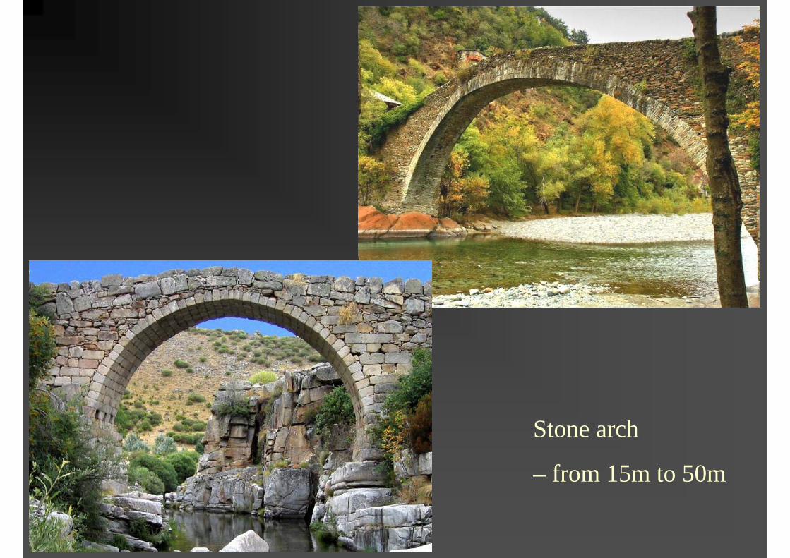
Stone arch
– from 15m to 50m

Steel Arch (framed or trussed) – from 150m to 500m

Sydney Harbour Bridge and its approach

Close up view of the bridge trusses

Close up of the bridge at the tower support

Steel arch-truss bridge crossing Pearl River Delta for the China Express Rail

Steel arch-truss bridge is very common and can be found in many parts of the world

Concrete Arch (ribbed or unribbed) –from 50m to 300m

Concrete Arch (ribbed) approx. 180m

Steel Arch – from 100m to 500m

The actual example – LuPoa Bridge, Shanghai (550m main span)

Cable suspension – from 400m to 1500m
The 1377m span TsingMa Bridge

Bridge anchor
Golden Gate Bridge in San Francisco

Bridge anchor
Rainbow Bridge in Tokyo

Cable stayed (multi-spanned) – from 50 to 500m per span
The 3-span cable-stayed Ting Kau Bridge

The Kap Shiu Mun Bridge, Lantau Link

The Nanpu Bridge, Shanghai

Nanpu Bridge and the approach bridge, Shanghai

Cable stayed span – from 200m to 800m
Actual example – the connecting bridge from Macau Mainland to the Island of Taipa in Macau

Example of box-sectioned steel girder bridge

A traffic interchange using large amount steel section deck for elevated bridges ( Rainbow Bridge, Toyko)


Structural Elements for Typical Bridges1. Foundation
foundation is required to support the bridge towers, portal frames or piers
Usual foundation methods such as H-pile, pipe-pile, bore-pile or precast concrete pile can be used for such purpose.
2. Bridge Tower
This is the vertical supporting structure only for cable suspension or cable-stayed bridges. The tower is usually construction in high-strength concrete using in-situ method. Mechanical climb form is most efficient for casting the bridge tower. In some cases, the tower can be constructed in a structural frame type.

The foundation of the bridge tower of Ting Kau Bridge on Tsing Yi side

The foundation for the Bridge Tower of Tsing Ma Bridge on the Tsing Yi side

Foundation of bridges may need to be carried out in very difficult location such as along an un-accessible slope

Structural Elements for Typical Bridges3. Pier is the vertical supporting structure for usual spanned
bridges. Pier is more suitable for bridge with maximum width of deck up to about 8m (2 traffic lanes). Usually bridge pier is constructed using in-situ method with large panel formwork.
4. Portal frameA portal usually consists on two piers on each side with cross beam in between to support the deck. In this case the width of deck can be up to 20m (6 traffic lanes).In some situations the height of a portal frame can be up to 50m from ground. Climb form can be used in this high-headroom cases.The erection of a complicated falsework system to support the portal construction is usually involved.

Forming the foundation for piers of elevated highway bridges

Forming the bridge formwork

Pier supports for an elevated roadway
A portal frame serving also as a transfer beam in the Route 3/Airport Railway at Kwai Chung

Falsework for the construction a portal frame

Single piers to support the bridge deck
Portal frame to support wider deck for multi-lane traffic

Bridge tower for Tsing Ma Bridge and Kap Shiu Mun Bridge
Tsing Ma Tower

Bridge tower for Stonecutter Bridge

Bridge tower & side span/approach bridge of Stonecutter Bridge

Structural Elements for Typical Bridges5. Bridge deck – the horizontal part of a bridge that support
pedestrian or traffic activities. The construction methods for the deck is shown in the following slides.
6. Bridge anchor – required only for suspension or cable-stay bridges to resist the pull from the suspension cable or counter-span of the bridge. Bridge anchor can be of gravity type using great mass for the counter-balancing, or using ground anchors for the same purpose.
7. Suspension cable – for suspension and cable-stayed bridges for the hanging, support or counter-balancing of the bridge deck

The forming of the cable anchor of Tsing Ma Bridge on Ma Wan side
(this is a gravity anchor weighting about 300,000 tons to resist the pull from the suspension cable)

The forming of the cable anchor of Tsing Ma Bridge on Tsing Yi side

Cable anchor of Tsing Ma Bridge on Ma Wan side with the suspension cable fixed
onto it. The anchor structure also serves as the abutment for the future bridge deck

Spinning of the suspension cable using steel thread (33000 thread each of 3mm diameter forming a 1.1m cable)

Forming the deck of the approach section of TsingMa Bridge on Ma Wan side using erection and hoisting approach

Forming the deck of the approach section of Tsing Ma Bridge on Tsing Yi side

Completing the deck of Tsing Ma Bridge (abutting section at Tsing Yi side) by erecting of the steel truss at spot

Hoisting and erecting of the modulated bridge deck for the Tsing Ma Bridge

Forming the bridge deck of Ting Kau Bridge using modulated steel girder frames

Laying the precast deck of the steel girder frame
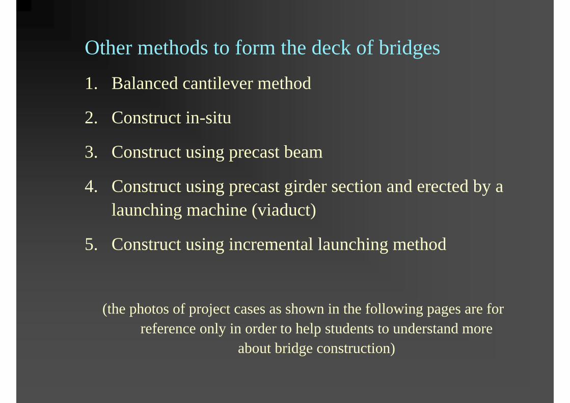
Other methods to form the deck of bridges
1. Balanced cantilever method
2. Construct in-situ
3. Construct using precast beam
4. Construct using precast girder section and erected by a launching machine (viaduct)
5. Construct using incremental launching method
(the photos of project cases as shown in the following pages are for reference only in order to help students to understand more
about bridge construction)

Forming the deck of using balanced-cantilever traveling formwork system

Detail of the traveling formwork system

Viewing inside the traveling formwork

Construction of a section of elevated railway track in the KCR Ma On Shan Line using in-situ method

Construction of an extension section of elevated roadway as part of the Tolo Harbor Highway extension project

Construction of a section of elevated roadway using in-situ methodSpecial points to note:
- The provision of a adequate falsework system to support the formwork with the weight of concrete during concreting process.
- Allow temporary road traffic on the ground level for general public or for site operation.

Usual falsework set-up for the construction of in-situ deck

Formwork and steel fixing work on the in-situ deck

The laying of precast beams to form the deck of the Route 3 elevated roadway at Kwai Chung. A truss-type launching machine was used for the lifting and positioning of the precast beams.

Hoisting of the precast beams using a special launching gantry
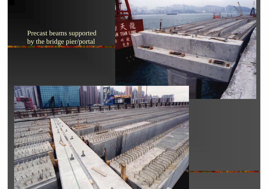
Precast beams supported by the bridge pier/portal

Precast concrete planks are used to cover the gaps between the beams

Construction of an elevated highway bridge using precast girder erected by the use of a launching machine
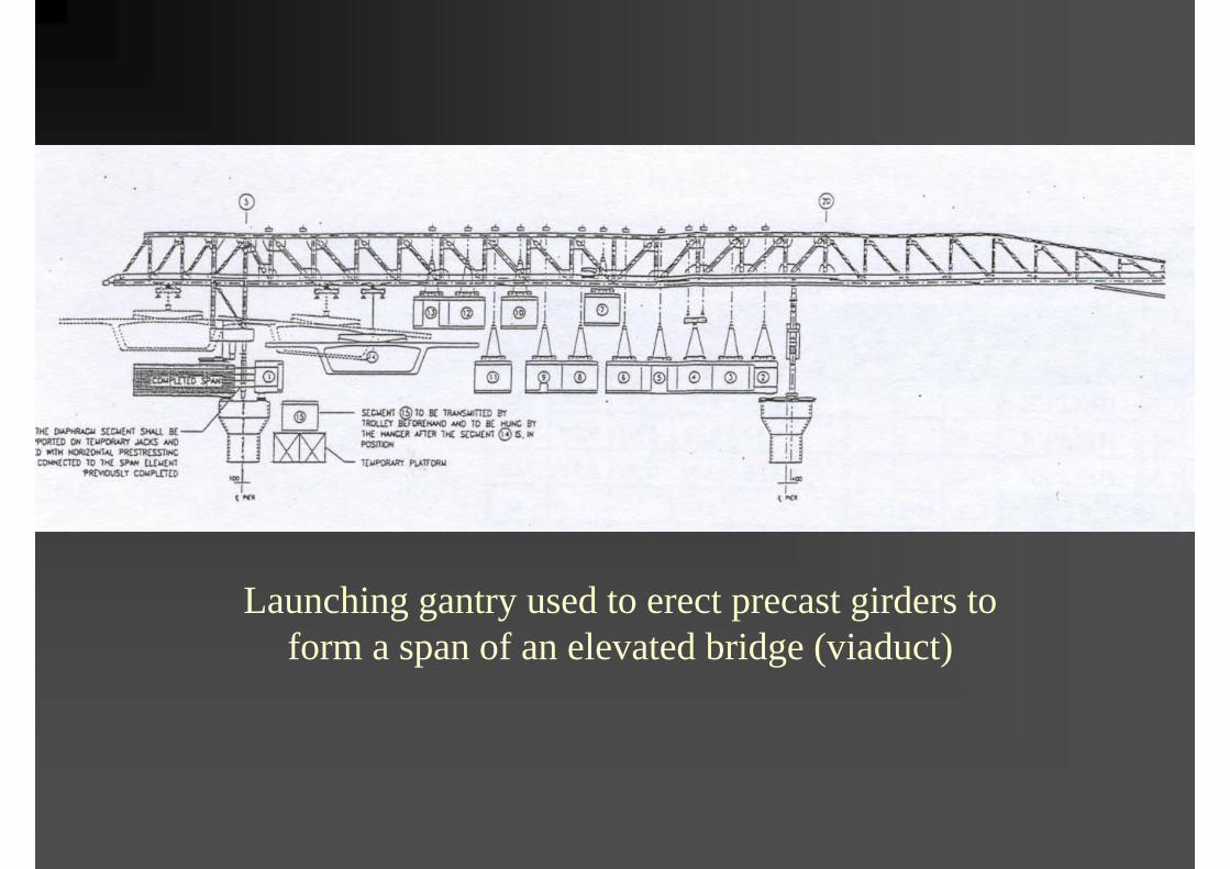
Launching gantry used to erect precast girders to form a span of an elevated bridge (viaduct)

Cast the first section of bridge
Push the first section of bridge deck outward using hydraulic jack. Use the same formwork to cast the second section of deck
Temporary support in the mid-span
Abutment or bridge pier to support the first bridge
Temporary support to be removed after the deck being tensioned
Concept of Incremental Launching method
Remaining roadwork to be continued on both ends of the span
Formwork to cast the 2nd
section of bridge deck

A bridge in the Fo Tan Road Improvement Project making use of Incremental Launching
method to span across the servicing KCR rail line
Alignment of servicing rail line

Constructing the linking bridge between Tung Chung and Chek lap Kok(the Airport Railway) using Incremental Launching method

– elevated roadway constructed in the form of viaduct

Route 3 – Kwai Chung Section

Route 3 – Country Park Section at Au Tau Interchange

Hung Hom Bypass

Tsing Yi North Coastal Roadway

Highway project in Ma On Shan

Launching gantry used in the Hung Hom Bypass

Launching gantry used in Route 3 at Au Tau Interchange

Launching gantry used in Tsing Yi North Coastal Roadway

Launching gantry used in the Ma On Shan highway project (T7)

Launching Gantry used in the Route 3 Kwai Chung section

Launching Gantry used in the Route 8 Tsing Yi Section


Layout of the bridge approach/interchange

The bridge approach/interchange after completion

Front leg
Master winch
Rear leg
Slave winch
Rear support
Hangers Front support
116m longMain Truss
(For end span and 1st pair segment erection)(SWL = 105 T)
(SWL = 120T)
Elevation of the Launching Machine

A review of other highway and railway bridges
– construction of the viaduct systems for the West Rail projects

Viaduct for railway track of the Kowloon Canton Railway West Rail at the northwesternpart of the New Territory, Hong Kong

Some sections of viaduct spanning more than 40m at Au Tau Interchange

Forming the viaduct for railway track using the under-slung girder and longitudinal beam supported method

Erection of the viaduct using balanced cantilever arrangement with temporary anchor before completion of a span
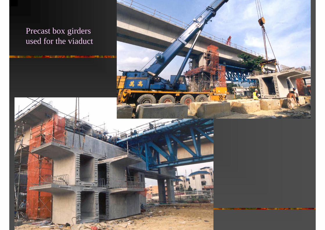
Precast box girders used for the viaduct

A section of viaduct with provision for an extension to the future northern link

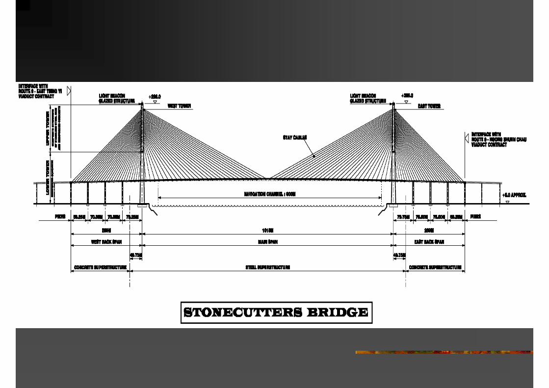
Case study –construction of the Stonecutters Bridge

Erection for main span steel deck segments


Lifting gantry for the lifting of the steel deck segment

The 1088m span of the bridge deck approaching its closing up at the mid-span.

Other innovative example of bridge form, the Helix, Marina Bay, Singapore
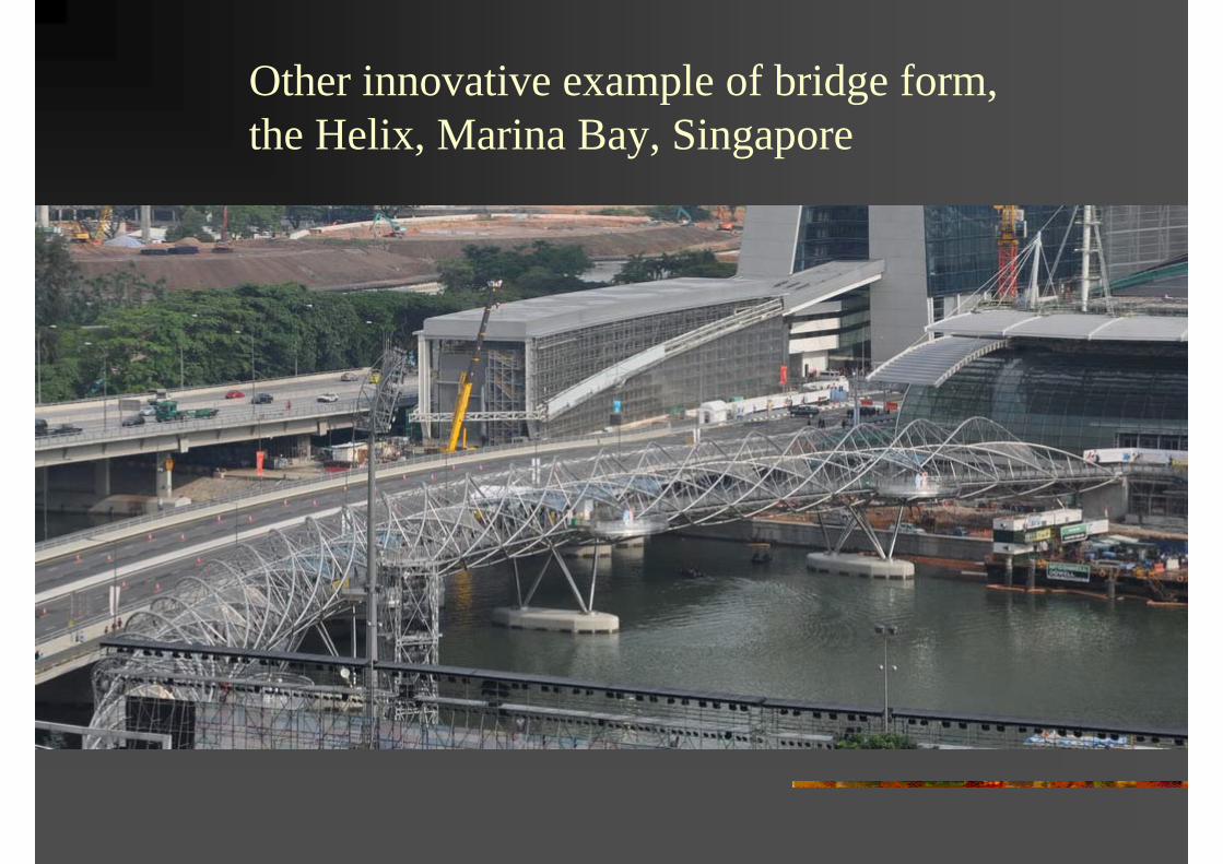
Other innovative example of bridge form, the Helix, Marina Bay, Singapore

Other innovative example of bridge form, the Helix, Marina Bay, Singapore

Other innovative example of bridge form, the Helix, Marina Bay, Singapore

The Helix, structural details

The Helix, structural details

The Helix, structural details

The end of the presentation