briatr-3170 brl technical report brl-tr-3170 - defense technical … · brltechnical report...
TRANSCRIPT

BRIATR-3170
TECHNICAL REPORT BRL-TR-3170
BRLA TECHNICAL ASSESSMENT
OF ELECTROMAGNETIC PROPULSION FORSMALL CALIBER WEAPONS APPLICATIONS
KEITH A. JAMISON
NOVEMBER 1990
APPROVED FOR PUBLIC RELEASE; DISTRBUTION UNLIMITED.
ao,3 Wqac73U.S. ARMY LABORATORY COMMAND
BALLISTIC RESEARCH LABORATORY -
ABERDEEN PROVING GROUND, MARYLAND Q/' ' -Q

NOTICES
Destroy this report when it is no longer needed. DO NOT return it to the originator.
Additional copies of this report may be obtained from the National Technical Information Service,U.S. Department of Commerce, 5285 Port Royal Road, Springfield, VA 22161.
The findings of this report are not to be construed as an official Department of the Army position,unless so designated by other authorized documents.
The use of trade names or manufacturers' names in this report does not constitute indorsement ofany commercial product.

UNCLASSIFIEDForm Approved
REPORT DOCUMENTATION PAGE OMB No. 0704-0188
Public repoting burden for this Collection of inormation is esmated to aeage hour per response, includig the time for revieing• tructions. sarching emitting data sources.gathering and maintaining the date needed, and coioleungm and reviwing the collecton of onformatoOn, lend commentof regardng t2i1 burden estimate or any other asct, of th•scollection of iformation,. . ncludig suggestions for reducing this burden. to Washington meadauarters S•rvmces. Direcorteor Information Operations and R-Dorts. 1215 Jefferson
Davis "ighway. Suite 1204. Arlington, VA 222024302. and to the Office of Management and Budget. Paperwork Reduction Protect (0704.0 1u5). Washngton. DC 20503.
11. AGENCY USE ONLY (Leave blank) 2. REPORT DATE 3. REPORT TYPE AND DATES COVERED
November 1990 Final, Oct 87- Oct 88
4. TITLE AND SUBTITLE 5. FUNDING NUMBERS
A Technical Assessment of Electromagnetic Propulsion PE: 61221Afor Small Caliber Weapons Applications
6. AUTHOR(S)
Keith A. Jamison
7. PERFORMING ORGANIZATION NAME(S) AND ADDRESS(ES) 8. PERFORMING ORGANIZATIONREPORT NUMBER
9. SPONSORING / MONITORING AGENCY NAME(S) AND ADDRESS(ES) 10. SPONSORING / MONITORINGAGENCY REPORT NUMBER
Ballistic Research Laboratory
ATTN: SLCBR-DD-T BRL-TR-3170Aberdeen Proving Ground, MD 21005-5066
11. SUPPLEMENTARY NOTESResearch sponsored by Close Combat Armament Center, SMCAR-CCL-FA, Picatinny Arsenal,NJ 07801-5001. Dr. Jamison is currently employed by Scienc'e Applications Inter-national Corporation, 1247-B North Eglin Parkway, Shalimar, FL 32579
12a. DISTRIBUTION I AVAILABILITY STATEMENT 12b. DISTRIBUTION CODE
Approved for Public Release; Distribution Unlimited
13. ABSTRACT (Maximum 200 words)
An assessment of the future potential of electromagnetic propulsion for smallcaliber weapons has been performed to consider possible benefits, systemsconfigurations, research and development needs, and mission requirements. Theassessment consists of a panel evaluation of an existing JSSAP electromagneticlauncher EML program and comparisons of envisioned point designs for smallcaliber weapons systems. The general conclusions are that the present researcheffort is well-founded and that EM propulsion has a great deal of potential for avehicle mounted, crew-served weapon. Although the potential improvements aresignificant, some risk in maturing the technology to a fielded weapon is accruedfrom the number and complexity of components in the EML system.
14. SUBJECT TERMS 15. NUMBER OF PAGES
RAIL GUNS; ELECTROMAGNETIC GUNS; ELECTROMACNETIC LAUNCHER; 86ELECTROMAGNETIC PROPULSION 16. PRICE CODE
17. SECURITY CLASSIFICATION 18. SECURITY CLASSIFICATION 19. SECURITY CLASSIFICATION 20. LIMITATION OF ABSTRACTOF REPORT OF THIS PAGE OF ABSTRACT
UNCLASSIFIED UNCLASSIFIED UNCLASSIFIED SAR
NSN 7540-01-280-5500 Standard Form 298 (Rev. 2.89)UUILA IlILUPrescritied by ANSI ltd Z39.18S~UNCLASSIFIED 3191-,02, ,,

INTENTIONALLY LEFT BLANK.
ii

TABLE OF CONTENTSPage
LIST OF FIGURES ............................................ v
LIST OF TABLES .............................................. vii
ACKNOWLEDGMENTS ....................................... ix
1. INTRODUCTION . ............................................ 1
2. COMPONENTS OF AN EML .................................... 4
3. JSSAP PROGRAM ............................................ 6
3.1 Background and Progress ..................................... 63.2 Program Plans ............................................ 93.3 Panel Discussions .......................................... 9
4. POSSIBLE MISSION APPLICATIONS ............................. 12
4.1 Configurations ............................................ 154.2 Targets . .................................................. 16
5. POTENTIAL BENEFITS FROM EML .............................. 17
6. R&D REQUIREMENTS ........................................ 21
6.1 Research Tasks ............................................ 216.2 Technical Barriers .......................................... 256.3 Suggested Milestones ........................................ 286.3.1 Projectile Milestones ..................................... 286.3.2 Power Source Milestones .................................. 286.3.3 Launcher Milestones ..................................... 296.3.4 Demonstrations of EML Systems ............................. 296.4 Cost Estimates ............................................ 30
7. NET ASSESSMENT ........................................... 30
8. CONCLUSION .............................................. 44
9. REFERENCES ............................................... 47
APPENDIX A: LIST OF PARTICIPANTS ........................... 49
APPENDIX B: SAMPLE SURVEY QUESTIONNAIRE ................. 53
iii
Page
APPENDIX C: ESTIMATION OF EML SYSTEM MASS ................ 61
APPENDIX D: ESTIMATION OF IMPROVED CONVENTIONALSYSTEM MASS ................................ 77
APPENDIX E: FACTORS NOT CONSIDERED ....................... 83
DISTRIBUTION .............................................. 87
iv
LIST OF FIGURES
DOMur Page
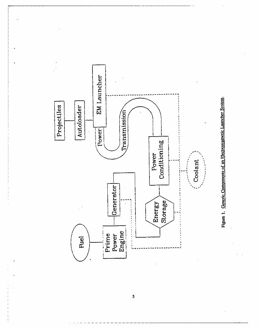
1. Generic Components of an Electromagnetic Launcher System .................. 5
2. Illustration of Factors Used for Comparison of EML and ImprovedConventional Systems ............................................. 32
3. Relation Between Estimated Compulsator Mass and Projectile KineticEnergy ........................................................ 33
4. Average Firing Rate and Stowed Load Which Permit Equal Mass EML and Future
Conventional Systems ............................................. 37
5. Variation of Point Design System Masses With Firing Rate .................... 39
6. Variation of Point Design System Masses With Stowed Load ................... 40
7. Variation of Point Design System Masses With Muzzle Velocity ................ 41
8. Variation of Point Design System Masses With Projectile Mass ................. 43
v

INTrEMrONALLY LEFr BLANK.

LIST OF TABLES
Table Page
1. Candidate Small Caliber Barrel and Projectile Specifications ................... 11
2. Conventional Gun System Parameters ..................................... 13
3. Point Design Estimates for Crew-Served, Small Caliber EML .................. 35
4. Point Design Estimates for Future Conventional Systems ...................... 36
C-1. Constants and Approximations for Estimation of EMLSystem M ass .................................................... 64
D-1. Comparison of Actual and Scaled Barrel and AmmunitionM asses ........................................................ 80
vii
INTENTIONALLY LEFT BLANK.
viii

ACKNOWLEDGMENTS
The author is grateful to Mr. Alex Zielinski, Dr. C. E. Hollandsworth, and Mr. Henry Burden for
their efforts in the technical review and editorial assistance in the preparation of this manuscript.
ix

INTENI-ONALLY LEFT BLANK.

1. INTRODUCTION
Concepts for electromagnetic propulsion devices with weapon-like performance have existed for
nearly 70 years (Fauchon-Villepl&e 1921). Interest in developing an electromagnetic gun has come and
gone several times, generally waning due to the lack of a sufficient power source (Hansler 1946;
Radnik and Bak 1958) to supply the energy mandated by the gun's performance parameters. The
factors which determine the power supply requirements are: the projectile mass, launch velocity, rate
of fire, and launcher efficiency. The present wave of interest stems from the success of researchers at
the Australian National University in the late 1970s, who accelerated a 3-g mass to 5.9 km/sec
(Rashleigh and Marshall 1978). Although the equipment utilized in this experiment was huge and not
weaponizable, the conversion of electrical energy to more than 50 kJ of kinetic energy at such high
velocity was a very significant achievement. Following this success, a reasonably aggressive program
has been established in this country aimed at improving launchers and making power sources portable.
Serious consideration was once given to developing a field artillery weapon. Presently, a joint Army,
Department of the Army Defense Advanced Research Projects Association (DARPA), and Defense
Nuclear Agency (DNA) program is underway to develop an anti-armor gun with an output of 9 MJ of
projectile kinetic energy. Space-based applications of electromagnetic launchers (EMLs) are also being
researched by the Strategic Defense Initiative Office (SDIO) and Air Force laboratories.
The central premise of any EML research or development program is that a more effective
weapons system may be devised when the projectile acceleration is achieved by electromagnetic
forces. It is generally thought that fielded, chemical propulsion weapons are not approaching any
fundamental limits of performance. However, over the years, the rather slow improvement in
projectile velocity and kinetic energy suggests that severe system burdens are associated with increased
projectile performance (Bechtol et al. 1983). The accepted problems in improving projectile
performance are:
(1) A need to select a larger bore gun tube and the weight penalties that propagate through the
system due to a heavier barrel.
(2) The tube lifetime is reduced as performance increases.

(3) Increases in system mass and volume result from the addition of more propellant. This is
particularly acute, as attempts are made to increase projectile velocity. Because efficiencies
decrease significantly between velocities of 1.0 and 2.5 km/sec, the required propellant mass
is more than proportional to the square of the velocity.
The problems with increasing the performance of conventional guns, as listed above, suggest
three straightforward goals for the developers of EMLs. First, they need to demonstrate improved
projectile performance in a similar sized barrel. Second, they must show that a higher performance
barrel can have an equal or greater lifetime than today's guntubes. Third, and probably the most
critical, they must show that the mass and volume penalties associated with the high performance
EML system are less than the size and weight additions expected if the performance of a conventional
weapon was increased. With minimal inspection, one might assume that the mass and volume of the
electrical generation equipment would exclude EMLs from competition as future weapons. One
important factor that may change this pedestrian analysis is that common fuels used in engines which
drive generators have ten times more energy per unit mass than typical munition propellants. If the
chemical gun is inefficient enough, or the stowed load of propellant is large enough, then EMLs mass
and volume may not be excessive. There are two strong considerations which must also be applied to
the third goal. One consideration is that the increase in performance is worth the extra burden the user
must bear, and the other is that the cost of the new system is justified by the increase in the weapon's
effectiveness. In the case of an EML-based weapon, the system may be large, placing a weight burden
on its platform, while the resupply burden can be quite small. These considerations may be more
applicable to development than to research, but long-range planning is usually valuable to the
researcher, especially when choosing priorities.
In 1982, the Future Weapons Branch of the Close Combat Armament Center, Dover, NJ,
embarked on a feasibility study of the potential of EMLs for small caliber weapons applications. The
program today has evolved into an effort to develop effective projectiles which can be launched by a
railgun and to demonstrate, in principle, a portable EML capable of salvo fire and delivering far more
projectile kinetic energy than an M2HB machine gun. The purpose of this report is to assess the
technical merits of the present research program. A direct evaluation would involve the dissection of
present program plans versus technizal progress over the years since the program was initiated. One
is, of course, tempted to take the global view and try to answer the question, "What can this emerging
technology offer to the future needs of the small caliber weapons user?" Because the technology is
2

still immature and so many unknowns exist, this report will attempt to address both areas, but with
reservations.
A panel of experts with very different backgrounds in electromagnetic propulsion was convened
at the request of the Joint Services Small Arms Office (JSSAP) to assist the author in the technical
evaluation. The panel members are listed in Appendix A. Those providing written evaluations are
denoted by the symbol "(E)." Each of the evaluators was asked to answer questions in the following
areas:
(1) Selection of future EML weapon systems.
(2) Assessment of possible benefits from EMLs.
(3) Ranking of necessary research tasks.
(4) Essay questions on the value of EML to the JSSAP program, technical barriers for EML,
suggested milestones for the program, and a cost estimate for the development processes.
Prior to the written assessment, the panel was given a briefing of the initial reasons for
proceeding in EML technology, program accomplishments to date, a review of other EML research,
and a brief overview of the weapons systems which fall under JSSAP's charter. Draft questionnaires
were then shown to the panel for comments and corrections as a method of explaining the evaluation
process. A group discussion was then conducted to obtain a cross-section of viewpoints on possible
component specifications. Topics ranged from maximum allowable pressure in a railgun bore to
energy and power densities of potential power train components. Several of these parameters are
discussed in Section 3.3 and utilized in Appendix C. Following the discussions, the panel members
provided written comments on the four-page questionnaire. The average scores and standard
deviations are discussed in the bodi of this report. A copy of the questionnaire is provided in
Appendix B.
The report is organized as follows. An explanation of the components necessary for an EML-
based weapon system is given, follcwed by a review of the JSSAP EML program. Next, three
sections give the panel's views on mission applications, potential benefits, and R&D requirements
needed to mature EML through a pre-prototype stage. A net assessment follows which attempts to
compare a future EML weapons system to an advanced, conventional gun system. A concluding
3
section summarizes the results and gives recommendations for improving the small caliber EML
program.
2. COMPONENTS OF AN EML
It must be remembered that when one is attempting to weaponize an electromagnetic launcher,
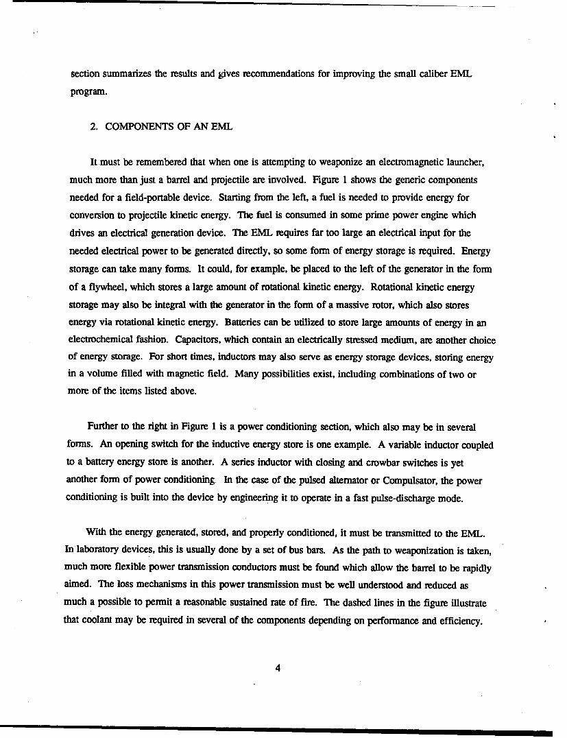
much more than just a barrel and projectile are involved. Figure 1 shows the generic components
needed for a field-portable device. Starting from the left, a fuel is needed to provide energy for
conversion to projectile kinetic energy. The fuel is consumed in some prime power engine which
drives an electrical generation device. The EML requires far too large an electrical input for the
needed electrical power to be generated directly, so some form of energy storage is required. Energy
storage can take many forms. It could, for example, be placed to the left of the generator in the form
of a flywheel, which stores a large amount of rotational kinetic energy. Rotational kinetic energy
storage may also be integral with the generator in the form of a massive rotor, which also stores
energy via rotational kinetic energy. Batteries can be utilized to store large amounts of energy in an
electrochemical fashion. Capacitors, which contain an electrically stressed medium, are another choice
of energy storage. For short times, inductors may also serve as energy storage devices, storing energy
in a volume filled with magnetic field. Many possibilities exist, including combinations of two or
more of the items listed above.
Further to the right in Figure 1 is a power conditioning section, which also may be in several
forms. An opening switch for the inductive energy store is one example. A variable inductor coupled
to a battery energy store is another. A series inductor with closing and crowbar switches is yet
another form of power conditioning In the case of the pulsed alternator or Compulsator, the power
conditioning is built into the device by engineering it to operate in a fast pulse-discharge mode.
With the energy generated, stored, and properly conditioned, it must be transmitted to the EML.
In laboratory devices, this is usually done by a set of bus bars. As the path to weaponization is taken,
much more flexible power transmission conductors must be found which allow the barrel to be rapidly
aimed. The loss mechanisms in this power transmission must be well understood and reduced as
much a possible to permit a reasonable sustained rate of fire. The dashed lines in the figure illustrate
that coolant may be required in several of the components depending on performance and efficiency.
4
- 0
• o0 ,),I C.)
i '
0
CL) 0S.c I... . . "
E
.0--
0ztIr4H

The rightmost portion of Figure 1 is the gun itself, with ammunition stowage in a magazine or
autoloader. The barrel, of course, must be aimed and fired, either by the soldier or by remote control,
if the weapon is mounted outside an armored, airborne, or sea-going vehicle. Since projectiles for
EMLs can be radically different from conventional ammunition, they too are shown in Figure 1 as a
reminder that significant development is also needed in this area.
It is, of course, possible to break the system in parts. With a large energy storage capability, one
may leave the prime power and electrical generation components in the resupply area. One can easily
envision trading depleted battery packs for charged ones when the weapons system is resupplied with
projectiles. Possibilities such as this, together with the large number of options listed above, make a
general technical assessment of the potential of the technology extremely difficult, if not impossible.
At the same time, the multiplicity of solutions to the system configuration may improve the chances
for harnessing EML technology for future weapons technology. Also, the range of possibilities places
on the developer the burden of maintaining currency in many rapidly advancing areas. Much of what
the developer must know is in the form of power and energy densities of the power train components.
Properties of the components for a specific configuration of Compulsator-driven railgun are discussed
in Appendix C. These specifications are used to project the mass and volumes of future weapons
systems. The projected values are estimates based on the FY95 - FY98 time frame when full-scale
development might begin.
3. JSSAP PROGRAM
This section offers a brief review of the small caliber EML program and outlines the future plans
through the 6.2 portion of the Research and Development (R&D) cycle. The direction of the present
program is generally built on the results and progress to date as well as technology developments from
other programs.
3.1 Background and Progress. At the request of the JSSAP office, the Future Weapons Branch,
Close Combat Armaments Center, Armament Research, Development and Engineering Center
(ARDEC) began to consider the possibility of utilizing electromagnetic launcher technology to
improve performance of small caliber weapons. A very short proof-of-concept program was
undertaken in which a small, one-meter long, 6-mm bore railgun was constructed and fired in a
laboratory setting using a capacitor bank. The limited success in this program (owing in part to its
6

very short schedule) indicated the promise of EML technology for future needs. Throughout the
lifetime of this project, the managers have maintained an excellent rapport with other government
organizations, national laboratories, universities, and industries. The scope of their affiliations has
been a very positive factor in the progression of this effort.
By fiscal year 1985, a more aggressive effort was underway. Four small contracts were placed
which would yield the answers directing the future research program. Those four contracts
concentrated in two general areas: launchers and power supplies. They identified the following
technical barriers to the development of EML-based weapons:
"* projectile/armature design
"* armature materials
"• rail materials
"* power transmission from supply to launcher
"* portable power generation and conditioning
"* minimization of system weight.
The barriers listed above are still a reasonably complete set with the exception of power
transmission, which has already been examined and appears to be a difficult engineering task rather
than an actual barrier. This relates to the rapid slewing of the launcher simultaneously with feeding a
large current to the breech.
The projectile/armature design has been receiving the most attention in the past two years. The
BRL has been involved in designing and firing an integrated armature projectile designed to be mass
stabilized (Zielinski and Garner 1990). The design has undergone some preliminary testing and is
awaiting higher velocity testing. In addition, some aerodynamic flight characterization has been
performed on these types of projectiles launched from a high pressure propellant gun (Garner,
Zielinski, and Jamison 1989). The decision between flying or discarding the armature is being
critically analyzed. Two designs, the present integrated armature and a newly-conceived, armor
piercing finned stabilized discarding armature (APFSDA) are undergoing extensive numerical modeling
to determine which provides the greatest terminal effectiveness for a given range and launch energy.
Initial modeling of the APFSDA has been started (Zielinski 1990).
7

Materials development for rails and armatures is likely to be far beyond the fiscal scope of the
JSSAP program. However, other EML programs with far more demanding materials needs are
addressing this issue, and the likelihood of a direct spinoff is high. As an example, the Air Force
Armaments Laboratory, which now has two Phase 11 Small Business Innovative Research (SBIR)
contracts for railgun bore materials, will very soon have as many as four armature contracts and a
significant effort in thermal management of railgun materials. Since the Air Force EML goals
mandate projectile kinetic energies up to three orders of magnitude larger than those in the JSSAP
program, even a partial success in the Air Force effort could completely solve the small caliber
materials needs.
The issues of portable electrical power and power conditioning were addressed in two of the
contracts started in FY85. One study addressed the possibility of a cartridge-based
magnetohydrodynamic (MHD) generator supplying power to a railgun (Butz and Levin 1986). This
was undertaken because of reports of MHD-railgun systems in the foreign literature, and also due to
optimistic claims of those working in the field. The outcome of that study was that an MHD-railgun
rifle was not considered to be technically feasible in the near future.
The outcome of the second power supply study (based on 1985 technology) concluded that the
only possible mission for small caliber EMLs was in the area of the vehicle-mounted, crew-served
launcher. Further, the Compulsator (or pulsed alternator/generator) emerged as the leading candidate
to generate and condition the electrical energy. This study assumed that salvo fire (a very rapid burst
of a few rounds) was a requirement. Early engineering estimates were that an armament system could
be envisioned which weighed approximately one ton (1,000 kg), which could fire 100 rounds per
minute, with each projectile having several times the kinetic energy of the present 50-caliber machine
gun, and which included a stowed load of more than 1,000 rounds. These estimates were not overly
optimistic as to weights of the individual components but did, of course, assume that projectiles and
launchers could be built to exploit the power generated by the Compulsator. A key factor also
identified in the follow-on power generation study was that the lead time for constructing the
Compulsator would be approximately 24 months, with an additional 12 months needed to characterize
the machine performance and complete testing with a railgun serving as the electrical load. Because
the long lead time in demonstrating the technology for a salvo fire EML was driven by the power
supply development, a considerable effort was expended in the latter part of FY86 to define the
requirements for a field-portable EML system. The goal of this device was to demonstrate that a
8

portable EML could launch projectiles with kinetic energies several times those typical of crew-served
automatic weapons.
The result of this planning effort, embodied as a statement of work, began the procurement cycle
a few weeks before the beginning of FY87. A contract was awarded to the University of Texas'
Center for Electromechanics in the last month of FY87. Several factors may have contributed to the
length of this cycle and thereby account for the minimal progress in the power supply area during
FY87. The delays due to these events, though not definitely quantifiable, must be considered when
evaluating the progress of power supply development for the small caliber EML program. These
changes, although reducing risk and immediate cost, will likely account for a one-year delay in
reaching the prototype stage.
3.2 Program Plans. The present plan calls for a projectile-intensive program and a
re-examination of the power supply selection rationale in FY88. Recently, some of the power supply
parameters have changed significantly, especially the energy density of capacitors. In 1985, capacitors
could store only 350 J/kg. The DNA has an on-going program to reduce the size of capacitors and, at
present, has demonstrated an energy density of approximately 2,200 J/kg. Final goals for the DNA
program are not known, but another factor of three improvement appears technically feasible. Here we
must stress that the figures above for both capacitors and rotating machinery do not represent
ruggedized, system-ready capacitors, but rather laboratory devices.
Detailed engineering designs have been completed for a two-pole air-core Compulsator, and
details concerning the machine's technical aspects can be found in Fulcher, et al. (1989), although the
design considered here is based on the demonstrated iron-core machine. In FY90, the laboratory
system is to demonstrate salvo fire of 32-g projectiles at 2 km/sec at 10 Hz in a three-shot burst.
The armature and projectile work in FY88 through FY90 is timed so that when the test bed
power and railgun are ready, an effective demonstration may be conducted showing not only that a
small caliber EML can produce weapon-like kinetic energy at the muzzle, but also that the output will
be salvos of highly lethal projectiles.
3.3 Panel Discussions. The panel's general view was that the research efforts as described were
well founded. Technical differences were, however, apparent and discussed in some detail. The first
9

concerned the selection of bore size barrel length, and projectile kinetic energy. The relation between
these parameters is calculable, given the acceleration profile and assuming that frictional forces may be
neglected. The panel was polled to obtain a collective opinion of the peak magnetic pressure and the
peak-to-average acceleration ratio readily achievable in a small caliber railgun. The dominant answer
for peak pressure was 347 to 416 MPa (50 to 60 ksi). Most agreed that the current per-unit rail height
was the controlling factor. This will permit higher pressures for augmented railgun designs. A peak-
to-average force ratio of 2.0 was taken as representative for the current waveforms of both the simple
Compulsator and the L-C resonant circuit. All agreed that envisioning a ratio as low as 1.2 was
unrealistic, but that a ratio of 1.8 is an achievable goal.
The parameters supplied by the panel's members were used to construct the data set shown in
Table 1. The bore dimensions and barrel lengths in the first and second columns span the range of
interest for crew-served weapons. The peak pressures bracket the upper bound considered possible by
the panel. Assuming a peak-to-ave:age driving force ratio of 1.8 and neglecting friction, the kinetic
energy is readily calculable. Note that a square bore configuration is assumed.
The panel members were also polled concerning the allowable acceleration, and their responses
varied dramatically. The values for allowable peak acceleration ranged from 50 kg's to 1 Mg, with
the average being about 300 kg's. One would hope that this reflects the panel's concern with large,
complex projectiles and lack of familiarity with small caliber rounds which must reach high velocities
in short barrels. The maximum acceleration values in column six of Table 1 were arbitrarily selected
to provide velocities in the neighborhood of the program goals. The velocity is calculated from the
barrel length, peak acceleration, and again assuming a peak-to-average accelerating force ratio of 1.8.
Finally, the total launch package mass is computed from the velocity and kinetic energy.
It can be inferred from Table 1 that the pressure required for the performance specified in the
present plan is larger by a factor of about three than what the panel views as possible. The first
recommendation offered by this report is that the railgun bore dimension be increased to 15 mm and
the length to at least 1.5 m.
Although neither the author no- the panel members are projectile designers, a second
recommendation of this report is to initiate a small basic research effort into the allowable
accelerations of small caliber railgun armatures carrying high-density payloads.
10

Table 1. Candidate Small Caliber Barrel and Projectile Specifications
Peak Peak Kinetic Max.Bore Barrel Pressure Pressure Energy Accel. Mass Velocity
(amm) (M) (ksi) (MPa) (kU) (kgee) (g) (m/sec)
7.62 0.60 45.0 310.3 6.04 350 5.3 1,5127.62 0.80 45.0 310.3 8.06 350 5.3 1,7467.62 1.00 45.0 310.3 10.07 350 5.3 1,9527.62 1.20 45.0 310.3 12.09 350 5.3 2,139
7.62 0.60 50.0 344.7 6.72 350 5.9 1,5127.62 0.80 50.0 344.7 8.95 350 5.9 1,7467.62 1.00 50.0 344.7 11.19 350 5.9 1,952*7.62 1.20 50.0 344.7 13.43 350 5.9 2,139
7.62 0.60 55.0 379.2 7.39 350 6.5 1,5127.62 0.80 55.0 379.2 9.85 350 6.5 1,7467.62 1.00 55.0 379.2 12.31 350 6.5 1,9527.62 1.20 55.0 379.2 14.78 350 6.5 2,139
12.70 0.75 50.0 344.7 23.32 300 19.0 1,56512.70 1.00 50.0 344.7 31.09 300 19.0 1,80712.70 1.25 50.0 344.7 38.87 300 19.0 2,02112.70 1.50 50.0 344.7 46.64 300 19.0 2,214
12.70 0.75 55.0 379.2 25.65 300 20.9 1,56512.70 1.00 55.0 379.2 34.20 300 20.9 1,80712.70 1.25 55.0 379.2 42.75 300 20.9 2,021*12.70 1.50 55.0 379.2 51.30 300 20.9 2,214
12.70 0.75 60.0 413.7 27.98 300 22.8 1,56512.70 1.00 60.0 413.7 37.31 300 22.8 1,80712.70 1.25 60.0 413.7 46.64 300 22.8 2,02112.70 1.50 60.0 413.7 55.97 300 22.8 2,214
15.20 1.00 50.0 344.7 44.54 275 29.7 1,73015.20 1.25 50.0 344.7 55.67 275 29.7 1,93515.20 1.50 50.0 344.7 66.81 275 29.7 2,11915.20 1.75 50.0 344.7 77.94 275 29.7 2,289
15.20 1.00 60.0 413.7 53.45 275 35.7 1,73015.20 1.25 60.0 413.7 66.81 275 35.7 1,93515.20 1.50 60.0 413.7 80.17 275 35.7 2,119*15.20 1.75 60.0 413.7 93.53 275 35.7 2,289
15.20 1.00 70.0 482.6 62.36 275 41.6 1,73015.20 1.25 70.0 482.6 77.94 275 41.6 1,93515.20 1.50 70.0 482.6 93.53 275 41.6 2,11915.20 1.75 70.0 482.6 109.12 275 41.6 2,289
* Launcher specifications have been selected for study in Section 7.
11

A third recommendation was evident in the written evaluation sheets. Several of the evaluators
felt very strongly that alternate power supply options should be tested. It is very important not only to
study the possible options, but also to perform adequate testing before downselecting. Clearly,
multiple programs developing different power supplies would exceed JSSAP's resources. A
compromise might be considered in which the scope of projectile work, armature research, and barrel
development are somewhat diminished so that each of the several groups could be encouraged to adopt
different configurations to power the research railguns. Regardless of the method, a competitive
distribution of power supply types among the hardware programs is a recommendation of this report.
4. POSSIBLE MISSION APPLICATIONS
The role of small arms is very significant to all branches of the military. The spectrum of
weapons which falls under the JSSAP charter is indeed rich. It ranges among personal-defense
handguns, automatic rifles, vehicle-mounted machine guns, and even grenade launchers. The present
JSSAP-sponsored program is limited to an R&D effort focused on crew-served, vehicle-mounted
automatic weapons which might serve as a future improvement for any vehicle presently incorporating
a small caliber machine gun as part of its armament. In past years, the program also examined the
feasibility of developing an EML-based sniper rifle, but the conclusion of that study was that success
would require breakthrough improvements in batteries and capacitors. Furthermore, research in those
areas was projected to be beyond the funding limitations of this program. An application of a
capacitor power supply supplying a sinusoidal-type current pulse has been considered for a machine
gun-type weapon, but will not be included here (Zielinski and Jamison 1989).
Since the application addressed by the present program has often been misunderstood, it appeared
worthwhile to poll the evaluators for their opinions of the segment of the broad spectrum of JSSAP
weapons over which EMLs could most significantly improve fire power. A sample of the performance
of three small caliber weapons and one cannon caliber weapon are shown in Table 2. The larger gun
is included for reference, since it is certainly higher performance.
The first sheet in the questionnaire (see Appendix B) asks the evaluators to rate the value of EML
technology to different weapons. Scoring was on a 0-100 scale, with 50 representing the point at
which risks and probable burdens equaled the potential benefits from an EML system. The average
12

Table 2. Conventional Gun System Parameters
Nomenclature M249 M60 M2 M242
Caliber,mm 5.56 7.62 12.7 25
Barrel length,m 0.46 0.58 1.14 2.03
Rate of fire,rpm 900 550 500 150
Burst size 3 5,10,20 5, 10,20 5
Barrel weight,kg 6.8 10.5 20.5 109
Ammunition M855 Ball XM948 SLAP XM903 SLAP M791 APDST
Projectile mass,g 4.0 3.4 23.0 105
Muzzle velocity,m/s 911 1218 1213 1343
Projectile kineticenergy,
kj 1.7 2.1 16.9 94.1
Cartridge weight,g 12.3 19 102 500
13

scores from all evaluators rated only the two crew-served weapons as worthy of the risks and burdens.
Listed below, in order of rating, are arbitrarily selected applications. The average score for each
application is listed with its title and is followed by the standard deviation of the scores.
* Crew-Served, 12-15-mm Machine Gun Rating: 84 ± 17 - This application was not only most
highly rated by the panel but also, as shown by the standard deviation, the panel members
were in better agreement than on any other system. The advantage of the larger bore system
is that, given equal magnetic pressures, the larger gun has twice the kinetic energy. The view
is that, as the need for greater projectile energy increases, electromagnetic propulsion becomes
more significant. Several of the evaluators cited anti-light-armor and antiaircraft as missions
for this system. Also, those who have built differently sized systems know that manufacture
of large bore railguns and armatures is somewhat easier.
* Crew-Served, 8-10-mm Machine Gun Rating: 80:± 19 - This configuration is not significantly
different from the one above except that the sizes of the electrical generation and energy
storage devices are likely to be half those required for the larger gun. The same prime power
could double the rate of fire in this smaller system. In terms of the R&D effort needed to
mature this system, several of the evaluators thought that less work would be required. This is
an important point to consider. The equipment costs in an R&D program should follow to
some degree the kinetic energy of the projectile. The small caliber program might serve as an
excellent subscale proving ground for programs with much larger energy requirements.
* Sniper Rifle Rating: 32 ± 34 - A flashless, nearly silent, high velocity rifle powered by a battery
pack and capacitor bank is an attractive research goal to fill obvious needs in covert fire. (A
Mach 6+ projectile is, of course, not silent.) However, the panel's rating would appear to
close the book on this application. Some evaluators did cite that, given a breakthrough in
batteries and the projected developments in capacitors, this might logically follow the
development of the crew-served weapon. One evaluator who has studied this system in some
detail believes the technology is not far away from performing this mission if the rate of fire is
slow enough to allow the riarksman to re-aim, and the total number of rounds for a single
mission is not large. The large standard deviation in the scores indicates that agreement was
not universal among the evaluators. Again, this application is not part of the JSSAP program,
although it was once considered.
14

* Automatic Rifle Rating: 25 ± 29 - For the combat rifle, EML power supplies are either very far
term or unimaginable. Further, it is difficult to envision the soldier drawing ammunition and
swapping large battery packs in a battlefield setting. In addition, large gains in performance
may result in a unacceptably large impulse on the soldier. The rating, in the estimation of the
author, is too high, possibly because the word "automatic" was inadvertently left off the
questionnaire.
* Grenade Launcher Rating: 15 ± 19 - This application has not been examined in detail, but may be
more suitable to a coilgun. Certainly, one does not need high velocity, so most of the claimed
electrical advantages are negated by the efficiency of chemical propellants.
* Shotgun Rating: 11 ± 26 - The rating is so low for this application, it hardly justifies discussion. It
is curious to note that this system showed the largest percentage standard deviation of all
applications.
* Hand Gun Rating: 10 ± 17 - As with the previous example, one should not consider EMLs when
hoping to improve performance without overburdening the user.
The purpose of the above exercise was to establish, via the opinions of technical experts in the
EML field, whether or not the correct weapon system had been chosen from the large number which
fall under JSSAP's charter. The universal conclusion is that the correct application is being pursued in
the present program.
4.1 Configurations. The platform for the crew-served weapon will undoubtedly impact the full-
scale development and the specifics of the final design of the first small caliber EML to be put into
service. The possibilities of weapon platforms (vehicles) vary greatly in this joint services program.
While even the pre-prototype program is a few years away, it is not too early to speculate on the
possible platforms for a crew-served EML. Because of the relatively large system mass and volume,
airborne uses may be limited to rotary wing, rear area, or defensive-type craft. Attack helicopters will
unquestionably need far more firepower, as will large defensive systems in a naval role. However, the
PT boat might be a very appropriate vehicle. Amphibious or simple landing craft could take
advantage of EMLs if their missions require a large stowed load of ammunition. Ground forces in
15

lightly armored vehicles, or even secondary guns on armored personnel carriers (APCs) and missile
launchers, could also benefit from the potential advancements of EMLs over today's armament.
Even in the far term view, the EML armament system will be applicable when large stowed loads
are required and when the power components can be integrated into the vehicle some distance from
the gun. Locating the power far from the gun suggests the need for a higher impedance launcher
(such as the augmented or multitum railgun) to reduce power train losses. Longer sustained firing
would be possible before too much heat builds up in the system. The question of coolant for the
power plant is difficult to resolve without exact mission scenerios.
The relative ease of remote control of an all-electric system, without the need for breech closure
or a cartridge case ejection system, may ultimately become one of the EML's strongest selling points.
The need for such remote control, given some estimations of the threat of nuclear, biological, and
chemical (NBC) capabilities, is likely to be ever increasing.
4.2 Tar-ets. Two general classes of targets exist for the crew-served weapon. Point targets
include personnel, equipment, supplies, and unarmored and lightly armored vehicles. Area targets
such as buildings and wooded areas require a high rate of fire and depend on a large number of
dispersed rounds to achieve a hit. In later sections, the prime power problems associated with high
rate-of-fire systems will be discussed. The gains that EMLs offer are strongly centered on addressing
point targets. The JSSTO document (1986) lists a need for a much greater terminal performance. The
reason may be obvious. If the armament on an unarmored vehicle can address lightly armored targets
outside the range of the threat, a significant battlefield advantage would exist. For the armament
system, this translates to effective projectile designs with increased kinetic energy. These are exactly
the aims of the JSSAP small caliber EML program. Other advantages possible with EMLs would also
be of value on the battlefield. The question of signature from the muzzle blast is very important to an
unarmored mount. One cannot expect an unarmored vehicle to announce its presence in close
proximity to an armored threat. When either the gun or target is moving, higher projectile velocity
will reduce lead angles and should increase hit probability. The ability of electromagnetic (EM)
systems to completely remove the driving force before the projectile exits the barrel and the absence of
propelling gases should reduce launch dispersion. These problems are far more acute for smaller
caliber projectiles than for larger ones.
16

5. POTENTIAL BENEFITS FROM EML
The author, rather than rely solely on his own opinions, asked a panel of experts to score the
potential advantages of EMLs on a 0-10 point scale. Since the risk and R&D effort required to
achieve a given advantage varies greatly among all those claimed, the panel was asked to reduce the
score of the possible advantage if it would be more difficult to achieve. The second page of Appendix
B is the potential improvement portion of the questionnaire. In addition to estimating a combined
rating and difficulty, the evaluators were asked to rank the improvements in order of importance to the
JSSAP program. The evaluators were also asked to list an alternate technology that would offer an
equal potential benefit in the area being considered. The following paragraphs are listed in order of
importance as determined by the evaluators. After each title, the average rating and the standard
deviation of the ratings are given.
Improved Lethality 8.1 ± 1.7 - Again, the central premise of EML technology programs is that,
ultimately, a more effective weapon will be developed and used. Although this advantage was
ranked first by the evaluators, the lower rating score than several other items reflects the
difficulty in achieving this potential. Also, any of the factors in this list could contribute to a
superior system, but lethality is generally considered to be the primary objective.
Several alternate technologies were listed which offered payoffs in this area. Electrothermal
(ET), Combustion Augmented Plasma (CAP), Ram Cannon, and a particle bed gun were all
suggested as candidates to be considered for improving lethality.
* Extended Range 9.0 ± 1.1 - Good projectile designs will permit extended range if higher muzzle
velocity is achieved. The increased range will not translate into effectiveness unless accuracy
and aiming promote increased hit probability. This benefit is therefore dependent on the
realization of other goals. Several evaluators listed decreased time of flight as a potential
benefit, especially if the weapon must address aerial targets or moving vehicles. Higher
velocity does reduce lead angles and, in general, simplifies the fire control solution.
Again, several alternate technologies were listed which offered payoffs in this area. ET, CAP,
RAM cannon, and a particle bed gun were all suggested as candidates to be considered for extending
17

range. All except RAM cannon will suffer launch accuracy problems due to muzzle blast as
performance is increased.
* Reduced Ammunition Logistics 8.6 ± 1.6 - This is the most realizable goal, since no propellant,
cartridge case, or primer is needed; the resupply logistics is reduced to extra fuel and
projectiles. The great reduction in ammunition vulnerability also impacts logistics and cost of
the entire chain from manufacture to use.
Liquid propellant is a propulsion technology which also has potential in this area. This is not
as significant as the advantage of EML, where a common fuel is proposed for gun and vehicle drive.
* Reduced Ammunition Vulnerability 9.2 ± 1.1 - The trade of chemical propellants for simple fuels
should make ammunition vulnerability reductions automatic. The drawback is that the total
armament system is large and may present a large target area. A hit in this area could do
more than make the gun inoperative. Energized portions of the EML power train will produce
some secondary effects if damaged by incoming rounds. These factors are not well known
and should be addressed prior to a prototype program.
Liquid propellant and Low Vulnerability Ammunition (LOVA) development efforts also show
promise in reducing the ammunition vulnerability.
* Reduced Signature 7.4 ± 3.9 - The elimination of all hot gases driving the projectile should greatly
reduce muzzle flash, smoke, and blast. Railgun armatures have not yet demonstrated this at
the required energy levels. For systems which are unarmored or lightly armored, this may be
a large battlefield advantage. Other signatures may be present, however, particularly
electromagnetic signatures from the switchgear.
No other technologies were thought to offer this potential advantage.
* Improved Safety 7.3 ± 2.8 - The relative safety of high power electrical generation equipment and
conventional munitions is very difficult to judge. It is evident that the evaluators were
comfortable enough with their own work in EMLs to believe that the electric system could
18

have a better safety rating than conventional systems with large stowed loads of high
performance ammunition.
RAM (Reliability, Availability, and Maintainability) 4.6 ± 2.0 - This rating reflects the multiplicity
of difficult engineering tasks to be addressed. This is especially true if EML systems are to
fire several stowed loads. The future EML system will be comprised of several complex
components; each will have its own probability of failure. To the author's knowledge, no
mean-time-between-failure studies have been attempted. Without such studies, even educated
guesses of availability are not possible. Clearly, with all the components needed for the EML
system, significant maintenance will be required. Reliability and downtimes must be carefully
considered before selecting EML as the weapon of the future.
An improved conventional propulsion system was to be selected if RAM was the prime
consideration in a future weapon.
"* Enhanced Accuracy 5.5 ± 2.0 - The accuracy of an EML is one area which has been almost totally
neglected. The evaluators ranked extended range very highly, implying that enhanced
accuracy is a firm requirement. The general belief among those in the EML field is that
electrical pulses are easier to control and reproduce than propellant bum cycles. Also, the
removal of the driving force before the projectile leaves the barrel and the reduced muzzle
blast should help improve accuracy.
"* Higher Rate of Fire 3.8 ± 2.6 - The evaluators' ratings indicate a potential problem. Chemical
energy is input to the breech of the 50-caliber machine at a rate roughly equivalent to 800 hp,
when the firing rate is 500 rounds per minute. Even if the generator and launcher in an EML
can be made highly efficient, the prime power engine will be of significant size and weight.
This will exclude very small vehicles from serving as platforms for the EML, unless the rate
of fire is reduced over today's capabilities. As previously stated, the user may wish to accept
reduced effectiveness against area targets to gain a large advantage against point targets.
"* Reduction in Component Logistics 3.9 ± 1.8 - This is almost a statement of the obvious. The main
components in the EML must each be hardened against failure if the logistics of spare parts is
to be manageable.
19

"* Variety/Novelty Projectiles 7.0 ± 2.3 - The possibilities of multiple types of projectiles has not been
fully explored, but does seem tractable. The more benign muzzle exit conditions should
produce fewer restrictions on the projectile designs.
"• Improvement in Environmental Factors 5.5 ± 3.3 - Engineering the EML to work in all types of
battlefield environments is a very difficult task. In the opinion of the author, this score is too
high. Laboratory EMLs are subject to failures with even relatively minor problems with the
environment. Dirt, mud, rain, salt spray, and snow are just a few of the factors which must be
considered in the weaponization of EMLs. A weapon of this type, which is not truly
weatherproof, is of little value.
"• Reduction in Recoil 6.8 ± 3.0 - For an automatic weapon, even if fixed to a mount, the recoil is a
significant factor in aiming all but the first shot. The EML eliminates the portion of the recoil
due to the propellant gases. Also, for equal kinetic energies, a higher velocity, lower mass
projectile imparts less recoil to the launcher.
* Ease of Fire Control Interface 6.3 ± 2.1 - For remotely aimed guns, advanced fire control, or
precision aim techniques, the relative ease of interface to an all-electric system will be an
advantage. This is a far term advantage, but is an excellent example of the growth potential of
EML.
* Synergism with Electric Vehicle 8.0 ± 2.1 - The probability that electric drive vehicles will appear
on the battlefield of the future is unknown. The maneuvering capabilities of an electrically
driven vehicle are clearly an advantage since the electric motor develops full torque even at
zero rotational speed. Electrically driven turrets are already in use today, so the inclusion of
significant electrical power within future vehicles does not appear totally remote. The sharing
of components between gun and drive train would certainly reduce the burden of an EM or ET
gun. As one evaluator put it, "The question provides the answer."
The above paragraphs reflect the optimism of those working in the EM field. Many of the
improvements will be very difficult engineering tasks. The general belief that no breakthroughs are
needed (except possibly in system mass and armature contacts) and that many of the basics have
already been demonstrated on the small caliber scale is, however, correct.
20

6. R&D REQUIREMENTS
All of the evaluators have been involved in planning R&D for some aspects of electromagnetic
launchers. Their judgement in the importance and sequence of the many tasks needed to mature
EMLs must be highly valued. The JSSAP program planners are strongly urged to study the following
sections as a guide to efficiently researching small caliber EMLs.
The third page of the questionnaire in Appendix B was discussed and edited by the panel prior to
the written evaluation. This worksheet lists 18 research tasks needed to advance the technology so
that a development decision can be made. The evaluators were asked to judge the relative importance
of each task, again on a 0-10 point scale. Also, panel members were to indicate a time frame in
which each task should be performed. The averages of the time frame scores are used to sequence the
following paragraphs from tasks which should be done early to tasks which should be done later. The
average "importance" score and the standard deviation are given after each task title.
6.1 Research Tasks.
* Armature Effectiveness 8.7 ± 1.3 - The function of the railgun armature is key to the ultimate
success of this program. The armature must maintain two good electrical contacts while
sliding at a high velocity, conduct the full railgun current without overheating, incur the
magnetic acceleration forces, and transfer these forces to the other parts of the projectile. To
date, solid armatures have not performed at the levels needed for the stated goals. Further,
many research efforts have revealed a certain randomness to the behavior of solid armature
contacts. To be effective, the armature should have low mass, maintain a very low (ten volts
or less) potential as it conducts current from one rail to the other, and accelerate a payload
larger than itself to a high velocity. This is an area where basic research is needed. As the
panel selection indicates, this effort should begin immediately.
• Armature Efficiency/Payload 8.1 ± 1.9 - There are a number of possible energy-loss mechanisms
associated with the armaturu. As an electrical element, it has both contact and ohmic loss
terms affecting the power supply specifications. Friction with the bore surfaces can consume
kinetic energy requiring additional power to be input to the railgun. If the aerodynamics of
the armature are unsuitable for high velocity atmospheric flight, it must be discarded from the
21

payload after launch. This represents an additional inefficiency, as all the kinetic energy of the
armature would be lost.
e Projectile Design - Target Effects 7.3 ± 2.5 - This task is key to the central premise of the EML
program. If a more lethal projectile cannot be delivered from an EML than from a
conventional gun, the program value will be greatly diminished. At this early stage in the
R&D cycle, a proof of principle effort is far more appropriate than an attempt to design the
ultimate projectile for a full-scale development effort.
* Projectile Design - Aerodynamics 7.4 ± 2.8 - The loss of projectile velocity and lethality between the
launcher and target is particularly acute in the small caliber systems. As with the previous
task, the design of a projectile to function well in an EML and still have good aerodynamic
characteristics is highly important to a decision to proceed from research to development. In
the case of small caliber projectiles, accuracy and range are also extremely sensitive to
aerodynamic effects. Both projectile design areas must be initiated early so that a worthwhile
package may be launched as launchers and power supplies become available.
* Barrels - Structural 8.6 ± 1.6 - The rather formidable kinetic energy selected as a goal for this
program requires a barrel which can withstand a high magnetic pressure. Further, this barrel
must be lightweight and maneuverable so that it may be quickly aimed by the soldier. Since
Section 6.2 will list rails as a technical barrier to launcher development, it should be pointed
out that the panel views the development of the barrel structure as more important.
* Power - Electrical Generation 7.6 ± 2.6 - As stated previously, the acquisition of a compact
generation device for a specific EML is a long lead time item. Devices which supply several
times the energy needed in this program have already been constructed and operated in a
laboratory setting. Compact electrical generation is seen more as a development issue than a
technical barrier.
• Barrels - Rail Lifetimes 8.4 ± 1.5 - Historically, gains in performance of conventional guns have
been accompanied with reduction in component lifetimes and reductions in reliability. If
22

higher performance is a genuine need, then the lifetime issue of raUgun barrels must be
resolved. As previously discussed, advances from other programs are expected in this area. A
demonstration of a barrel which can fire more than 100 rounds without serious degradation is a
worthwhile milestone.
"* Power - Energy Storage 7.1 ± 2.0 - In laboratory experiments, capacitors and inductors have served
quite well as energy storage devices. Work is needed in size and weight reduction before the
final selection of energy storage is made. Thermal management has not been adequately
addressed for any of the types of energy storage under conditions of sustained rapid fire.
"* Power Transmission 6.3 ± 2.7 - In any practical configuration, the launcher and power supply will
be at different locations in the vehicle. This requires efficient transmission of high current
power pulses to the gun. While the resolution of this problem will fall largely in the systems
integration package, issues such as firing with a moving launcher must be addressed early.
"* Power - Switchgear 5.7 ± 2.7 - The bulk of the EM community is researching systems with far
greater power and energy requirements than the small caliber effort. Larger systems must have
significantly more robust switchgear. This is an area in which spinoff from other research
endeavors will have a very positive effect in small caliber R&D. Solid-state switches are also
progressing as a result of influences other than EMLs. Solid-state devices exist today which
are nearly compatible with the needs of the JSSAP program.
* Barrels - Reduction of Losses 7.0 ± 2.5 - For very rapid fire, particularly in sustained missions,
ohmic and frictional losses in the barrel must be minimized. Results from other programs
suggest that this may not be a difficult technical issue especially if more effective projectiles
permit a reduced firing rate.
* System Engineering - Volume Economy 6.9 ± 1.9 - Limiting the volume of an EML system may
prove to be the most challenging task of vehicle integration. The ammunition stowage will
require a very small part of the system volume, while the prime power and energy storage will
require the largest portion.
23

"* System Engineering - Weight Economy 6.4 ± 2.1 - All three systems, issues, volume, weight, and
RAM, were rated relatively low. This may be an indication that they are development issues
rather than research tasks. Research is needed to prove that a realizable connection exists
between laboratory devices and a system concept which will be attractive to the user.
"* Utility Analysis 7.8 ± 1.9 - This task was rated as the fifth most important by the panel, even though
it does not require an early start. All the component performance parameters depend strongly
on the mission. Research in all areas could be simplified if a single set of system
specifications were selected by a well-executed utility analysis. The drawback to this approach
is that before all the fundamental restrictions are known, an incorrect choice of mission might
be made.
"* Thermal Management 5.9 ± 2.1 - Again, in this area, because the power and energy requirements are
so much lower than the systems, most of the evaluators are concluding that rejection of heat
due to electrical or frictional inefficiencies does not seem to be a pacing issue. Depending on
the fire rate and the length of each mission, thermal management may be a very important
issue.
* System Engineering - RAM Issues 5.6 ± 2.6 - Reliability, availability, and maintainability will be
among the leading factors should this research lead to a full-scale development program. The
power supply portion of the system will be complex. Quality control must be high if one
expects EMLs to have a reasonable RAM record. With so many unknowns and technical
issues, RAM issues should be held for later efforts.
* Power - Prime Engine 4.4 ± 2.6 - Engines which can deliver the required power exist today. The
only issues which remain are adaptation to the EML power train and vehicle integration. As
stated above, system volume and weight can both be significantly reduced by improving the
driving engine.
* Armature Signature Reduction 4.8 ± 2.2 - The conclusion based on the scores given this task appears
to be that if the armature functions well both electrically and mechanically, the signature will
be extremely small. The goal of eliminating muzzle flash and most of the blast will be
achieved by reducing the current to zero before the armature exits the launcher.
24

One inference which may be drawn from the high scores given many tasks is that the technical
risk is compounded by the number and complexity of the components which comprise an EML
system. This is the view of the author and many of the panel members. While the risk in rapid
development is high, the possible benefits and growth potential are also very high. The risk of this
program is greatly reduced by the complementary nature of several other EML programs and by the
realistic time lines which have been adopted. These possibilities certainly justify research in this area,
though perhaps not with huge expenditures. The situation certainly does not permit the omission of
regular critical reviews.
6.2 Technical Barriers. The term "technical barrier" has become popular when relating research
efforts to their long-term applications. As is typical for these terms, Webster's Third New
International Dictionary (Unabridged) offers seven definitions of the word "barrier." There are two
definitions which might be applied for our purposes. One is "an obstruction which prevents progress"
and the other is "a hindrance which impedes progress." The latter definition is more appropriate here.
There are no obstructions which must be removed, or new pathways found around them; rather, there
are areas in which work is needed before the total system will be attractive to the user. This work will
take time and resources to complete. If the problems in these areas are not solved, the end item will
be degraded in value but not become impossible to build.
The following paragraphs describe the impact on a future EML if the technical barriers cited by
the evaluators are not solved. The sequence of the list is determined by the number of times a barrier
was cited in the 14 written evaluations. Although the list is extensive, the collective view is that most,
if not all, of these issues could be resolved with R&D efforts in a reasonable time.
* Long Life Rails/Barrel - Most laboratory railguns suffer erosion and gouging of the bore, so that
only a few firings are possible before replacement or refurbishing is necessary. Railguns with
injectors have longer life, and sections of the bore where solid armatures have functioned properly
show almost no wear. If a long-lived bore cannot be developed, then the user will be burdened
with frequent replacement of the barrel and the logistics/battle management problems which
result.
* Compulsator Function - The prog-am as structured now is based heavily on the use of an air-core
Compulsator which is not a proven device. If problems are found in the Compulsator, an
25

alternate power train must be employed. This will increase both the volume and mass of the
system, but the magnitude of the increase is difficult to predict.
Effective Armatures with 2 km/sec Sliding Contacts - To date, the highest repeatable velocity at
which an armature has maintained good sliding contact has been 1.1 kin/sec. If no improvement
can be achieved, this may be the maximum muzzle velocity of the EML, and many of the
performance advantages will not be realized. If this is unacceptable, then a transitioning armature
may be used, and the user must accept the flash, inefficiency, and bore erosion problems
associated with plasma armatures.
* Projectile Design - The design compromises between launch environment, aerodynamics, and
terminal effects may restrict the lethality of the EML round. If no improvement can be made
over today's capabilities, the user must consider secondary factors such as muzzle flash and
logistics in assessing the value of EMLs to the battlefield.
* Efficiency - Inefficiency in any of the components has two consequences. First, the waste energy
must be expelled from the system, and second, all components which supply energy to the
inefficient section must be increased in capacity. More robust coolant systems and increased
system size are the penalties when high efficiency cannot be achieved. If these cannot be
tolerated, fire rate or projectile kinetic energy may be reduced.
* Barrel Design - The launch tube is the hardware which must withstand the reaction forces associated
with imparting the desired kinetic energy to the projectile. If high pressure railguns cannot be
designed, then a larger bore launcher and a discarding sabot and armature will be required. An
optimization must then be performed weighing a larger total system mass against reduced kinetic
energy arriving at the target.
* System Mass and Volume - If the total EML system is too large for a given vehicle, the
performance must be scaled down or the vehicle redesigned. Both options are critical to the user.
* Systems Integration - Even if the mass and volume of the system are within the platform constraints,
the required layout may prevent simple integration of the launcher and vehicle. Again, lack of
success in this area leaves the unpleasant choice between vehicle redesign and reduction of fire
26
power. Since little study has occurred in this area, it is difficult to judge the magnitude of the
system integration problem.
Thermal Management - This area assumes importance when one cannot achieve the efficiency
needed to operate for a sustained mission without overheating some portion of one or more of the
components. As an example, the rail surface may become very hot during a shot and not recover
before the next firing. Failure in this area will result in reduction of firing rate or the addition of
cooling systems. In an extreme case, a highly complex, perhaps even cryogenic, coolant system
might be required.
"• High Current Switches - In the laboratory, most railguns rely on switches which cannot be
weaponized. If solid-state switches do not progress to the level needed for the small EML, an
alternate path may be needed. For many power configurations, the projectile can function as one
of the switches. This will result in the so-called "hot rail" configuration in which one rail is
subject to the full power supply voltage for some length of time before firing. Safety and
environmental factors such as keeping the bore dry and clean will be harder to resolve.
"* Prime Power - Present machine guns and automatic rifles have very high rates of fire. To duplicate,
this rate of fire requires a significant power rating for the prime engine. Failure to weaponize a
turbine or other lightweight drive engine will result in either a much heavier system or a much
reduced rate of fire.
"* Recoil Management - The extra recoil which accompanies increased projectile kinetic energy must
be transmitted to the vehicle via some mounting bracket. This may require a damping
mechanism to hold the barrel, a much stronger bracket, or even place limits on the locations on
the vehicle where the launcher may be mounted.
The list of work areas above is reasonably complete for both initial research and the early stages
of development. Other EML programs are also addressing these same issues so that the removal of
these barriers is not the sole responsibility of a single program. For nearly every "barrier," the small
caliber requirements are less demanding than the requirements to be met in other EML programs. The
technical leverage the JSSAP prognan receives from other efforts is indeed large. One would expect
the JSSAP program managers to be able to quantify the state-of-the-art in each area before the
27

beginning of a 6.3A effort. Further. they should be able to show either projected improvements or an
assessment of the impact of negative results on the desirability of the projected system. This must be
done carefully before any large expenditures of development resources.
6.3 Suggested Milestones. The milestones listed by the evaluators were quite varied so that
compilation of the input is difficult. Four general areas of milestones were evident: projectiles, power
supplies, barrels, and system demonstrations.
6.3.1 Projectile Milestones.
(1) Define Performance Specifications - At the earliest possible time, and at re-evaluation points,
define the goals for the projectile in terms of range to target, kinetic energy on target, and time of
flight requirements. This information is essential, as projectile design compromises take place
among interior, exterior, and terminal ballistic performance.
(2) Prove Sliding Armature Contacts at 2 km/sec - A key advance in high-speed nonarcing armature
contacts is needed if the projectile velocity is to exceed today's capabilities.
(3) Design a Functional Armature at 2 km/sec - Once armatures have been made to function, they
must also be able to accelerate payloads. For terminal effects, a high density, high aspect ratio
component is likely to be the payload of choice.
(4) Demonstrate a Flyable, Effective Projectile - This demonstration is the goal of the projectile
program. Optimization where possible is, of course, beneficial.
6.3.2 Power Source Milestones.
(1) Perform Comparison of Power Train Options - The application of any of the potential power
trains to this program has a moderate risk. Comparison studies not only assure that the best
option has been chosen but also help define the back-up candidate power sources.
28

(2) Complete Power Source Design - A design for any of the demonstrations listed below should
include the launcher performance as a result of the power pulse delivered. If this is done early, it
will benefit both the launcher and projectile designers.
(3) Demonstrate Power Supply on a Single-Shot Launcher - The first tests of a power train should use
heavily diagnosed, single-pulse discharges into dummy loads and then into a launcher.
(4) Demonstrate Power Supply with Multi-Shot Firings - Since salvo fire is important to this mission,
the power supply should demonstrate single-salvo and then multiple-salvo firings.
6.3.3 Launcher Milestones.
(1) Evaluate Railgun Concepts - There are several different configurations for railgun launchers.
Among these designs are augmented, multiturn and multirail type configurations. Each has its
own internal pros and cons as well as an impact on the other system components. Ranking of
candidate configurations should be completed early as input to the projectile and power supply
designers.
(2) Launcher Design - A design for the demonstrations below is necessary for review by researchers
in all other areas, especially the armature program.
(3) Multi-Shot Barrel- A reasonable milestone is to complete, without launcher refurbishment, a ten-
shot sequence which shows no degradation of performance. Also, a second milestone, a 100-shot
test, is highly recommended.
(4) Conduct Simplified Dispersion Tests - Since no information exists on the accuracy or dispersion
of EMLs, a simple experiment in this area is required as soon as a launcher capable of many
rounds is available.
6.3.4 Demonstrations of EML Systems.
(1) Rapid Fire, Laboratory EML - This is essentially the demonstration that the present University of
Texas, Center of Electromechmadcs (UT-CEM) contract (DAAA21-87-C-0206) requires. It should
encompass many, if not all, of the milestones above.
29

(2) System Definition - As performance limits and component specifications become known, an effort
should be made to describe a "best guess" future armament system.
(3) System Integration Study - The lore in this area suggests that the integration task can never begin
too early. Candidate platforms should be surveyed for weight and volume availability. Estimated
layouts of all system components should be performed on a simplified basis, checking for special
restrictions on the power train and launcher.
(4) Pre-Prototype - Assuming moderate success in all of thp above, the transition to 6.3A
development should begin with a review and assessment of the potential benefits and burdens
which must be accepted by the user.
6.4 Cost Estimates. Each of the evaluators was asked to estimate the cost of maturing EML
technology through the prototype stage. It was evident that many of the evaluators chose different
definitions of the word "prototype." Most considered only the research lab demonstration and early
projectile work. These estimates were in the $3-5 million range. An average for those who totaled
the cost of a lab demo, a pre-prototype, and a prototype program is around $60 million. The costs are
driven by the success or failure in each task and are also strongly dependent on the fire power which
is chosen for each of the demonstrations.
The ultimate cost of an EML armament system is very difficult to predict. It is safe to assume
that the capital investment for an EML armament system will be far greater than today's costs. This
cost will be offset by the elimination of propellant and cartridge cases only if the system can be made
reliable enough that very large numbers of rounds can be fired without significant repair and
replacement costs.
7. NET ASSESSMENT
The most difficult task in this .,valuation is to determine if there are clear technical reasons for
believing that EMLs can mature into weapons systems with definitive advantages over other systems
that might be available in the same time frame. Although there are many approaches to answering this
unanswerable question, the comparison of envisioned equal risk, equal burden, and point designs is as
attractive as any. As desirable as the net assessment may be to the research planner, it is full of
30

conjectures and assumptions. Further, if the assessment is done by a technologist working in a
particular area, a bias is almost certain to be included. Considering the difficulties listed above, the
reader is cautioned to keep this assessment in perspective. Like the author (who has been engaged in
EML research for the last ten years), all of the evaluators have backgrounds in the EML field.
The comparison process is illustrated in Figure 2. Central to the assessment is the point design of
an envisioned future weapons system. It has a projected utility determined by its platform and the
targets it will address. The targets and the specifications of the system components will set limits on
the gun performance. One must be assured that the platform vehicle is not overburdened. Since this
new weapon concept is proposed for the future, one must not make comparisons to today's
capabilities, but rather to systems with projected improvements. Ideally, one would select
developments in both systems posing equal risk, but this is nearly impossible. For the purpose of this
assessment, we will project eight to ten years into the future, which is the earliest point at which full-
scale development (FSD) could begin on small caliber EMLs. To achieve a baseline of comparison, at
least three of the six items of the triangle in Figure 2 should be similar for both the EML and
advanced conventional technology. Certainly, the component specifications cannot be matched. If the
gun performances are the same, equal target effectiveness may be assumed. The projected point
designs will be adjusted so that equal performance and system burdens will be compared. Burden is
defined here as the total weight of the armament which the platform must carry. In designing the
EML system, there are two relatively easy methods of changing the system weight. First, the rate of
fire may be adjusted to change the prime power, and second, the stowed load may be adjusted to
change the total armament weight.
The methodologies for estimating the mass of future EML or improved conventional weapons
systems are briefly described in Appendices C and D, respectively. Details of the specific equations
used to estimate various weights and volumes are available in the computer codes at the end of each
appendix. Both the electromagnetic and the conventional estimations use energy- and efficiency-
oriented methods with scaling relations liberally applied to obtain representative values of component
mass and volume. Perhaps the most critical estimate for the EML system is the mass of the
Compulsator. Figure 3 reflects the uncertainty of estimating the Compulsator mass. The region
between the upper and lower curves brackets the conceptual design points from uncooled iron-core
Compulsators to cryogenically-cooled air-core Compulsators. In both conceptual designs, the
31

00
4--) G>
Q0 ) E
-L4-
00
00r
* -8
a.))>0
4.4) 4-.
00 U 0.aa.)
32SO
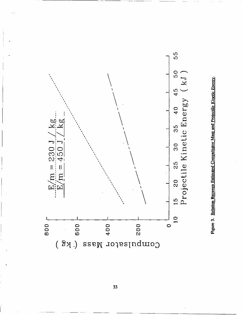
Lo
Lnd
C:.)
% %
, , 5 0 •
f DO -DOO
s~sD
% C\2
% % 0
00 0 C 0C 0 0
(:.) ss-eW iolesInduuoo
33

Compulsator was sized to fire throe-shot salvos from its own rotational kinetic energy. The
Compulsator mass is plotted as a function of kinetic energy of a single projectile, given the
inefficiencies as described in Appendix C. In reality, these machines must store many times the
energy needed to fire a single round. This makes the Compulsator a fairly natural choice for burst
firing if the burst does not consist of many (more than 10) rounds. The energy density rating is based
on the energy which appears on the output of the Compulsator in each of the three pulses. The
computer code in Appendix C reduced this single pulse energy by the railgun, armature, and power
transmission inefficiencies to obtain the projectile kinetic energy. The railgun and transmission
inefficiencies are treated as electrical loss terms, while the armature inefficiency is treated as a mass
which must be discarded from the launch package. The term "projectile" is reserved for the body
which flies to the target. While one may feel justified in assuming the higher Compulsator energy
density curve, the inclusion of a cryogenic cooling system appears unlikely for a fielded small weapon.
A conservative estimation of the pulse energy density of 270 kJ/kg seems reasonable for the near term
and is selected for the computer code. Wehrlen and Gully (1986) did point out that better
ferromagnetic materials were available and would reduce the mass of an iron-core machine. The
selection of this energy density is arbitrary, but is considered to lead to a realistic projection.
In all, masses of ten items are included in the sum of the system mass. These items comprise the
lower block in Table 3, which is a printout summary sheet from the EML estimation code. The
launcher parameters used as input in the calculations are selected from the candidate options given in
Table 1 of Section 3.3. These parameters were calculated from more fundamental properties suggested
by the panel as appropriate for small railguns. The rate of fire and number of rounds stored in the
high speed autoloader are arbitrary inputs at this point, but have been selected to match a chemical
gun system with identical projectile performance parameters.
The mass estimation technique for the future conventional system is outlined in Appendix D.
The output of this technique is highly sensitive to two assumptions. The first is the efficiency of the
chemical gun which decreases as velocity is increased. A simple relation between efficiency and the
inverse of the muzzle velocity has been selected. A more rigorous interior ballistic calculation should
be implemented if system parameters become more clearly defined, or if more accuracy is deemed
appropriate. The second assumption, which is a critical factor in the system mass estimation, is the
autoloader scaling relation. Again, if mission requirements become more exact, this scaling relation
should be replaced by an engineering estimate of the mass of an actual conceptual design. Table 4 is
34

Table 3. Point Design Estimates for Crew-Served, Small Caliber EML
INPUT PARAMETERS TOTAL SYSTEM VOLUME(excluding barrel)
Launch Package Mass 20.9 gBarrel Length 1.25 m 0.60 m3
Stowed Load 2575 rounds (21.1 ft3)Muzzle Velocity 2021. m/secBore Diameter 12.7 mm COMPONENT RATINGSFire Rate 240.00 rounds per minute(Three round salvo, 0.75-second pause) Compulsator Energy 2613 kJ
Turbine Power 951 HpCOMPONENT VOLUME(full stowed load) COMPONENT MASS
(full stowed load)Fuel 0.111 M3
Rail Coolant 0.123 m 3 Fuel 66.9 kgCompulsator 0.08 m 3 Rail Coolant 73.7 kgTurbine 0.238 m3 Compulsator 484. kgRecoil Mechanism 0.004 m3 Turbine 219. kgCompulsator Coolant 0.035 m3 Recoil Mechanism 6.9 kgAutoloader 0.018 m 3 Compulsator Coolant 35.3 kgPower Trans. 0.010 m 3 Autoloader 44.8 kgBarrel 0.011 m3 Power Transmission 50A kg
Barrel 20.7 kgCALCULATED PARAMETERS Projectiles 53.8 kg
Projectile Mass 17A6 g EXPENDABLES PER SALVOUseful KE 35.69 kJ (three shots)Acceleration Time 1.30 msPeak Current 554 kA Fuel 0.067 kgRail Thickness 1.28 cm Rail Coolant 0.086 kgMass of both rails 4.80 kg Compulsator Coolant 0.041 kgPeak Acceleration 300.1 kg Projectiles 0.063 kgLaunch KE 42.7 kJPeak Bore Field 17.5 Tesla TOTAL SYSTEM MASS 1055 kgCurrent Density 437 kA/cmPeak Pressure 55.3 ksi TOTAL RESUPPLY MASS 229.8 kgDrag Losses 3.0%Bulk Rail Temperature Rise Per Shot 39.00 CBreech Rail Surface Temperature Rise 910 CRailgun & Armature Efficiency 30.4%
35

Table 4. Point Design Estimates for Future Conventional Systems
INPUT PARAMETERS ESTIMATED COMPONENTS
Kinetic Energy 35.69 kJ Barrel 59.6 kgStowed Load 2575 rounds Cartridge Mass 206 gMuzzle Velocity 2021 m/sec Autoloader Volume .34 m3
Fire Rate 240.00 rounds per minute(Three round salvo, 0.75-second pause) TOTAL RESUPPLY MASS 532 kg
TOTAL SYSTEM MASS 1055 kg
a sample estimate of the future conventional system which has been done for comparison to the EML
system as listed in Table 3.
The point design selection above is, of course, arbitrary. The technique for matching the system
masses is worthy of some discussion. For the estimation technique presented here, the four factors
which contribute most strongly to the system mass approximation are:
"* rate of fire
"• number of stowed rounds
"* muzzle velocity
"• projectile mass.
The selection of the last two parameters reflects the viewpoints of the panel. The first two
parameters are used to match the EML and future conventional system masses. In principle, a rate of
fire could be selected and a stowed load computed which will give both systems equal mass. The
inverse is true only if the arbitrary stowed load is large enough to offset the EML generation
equipment. Figure 4 shows the relation between firing rate and number of rounds stored if both the
EML and future conventional system masses are constrained to be equal. The minimum stowed load
under these assumptions is slightly less than 2,000 rounds. The actual number of rounds stored to
achieve this matching of conventional and EML system masses is dependent on the technique,
launcher parameters, and assumptions. It may be generally true that the stowed load must be
significant if an EML system is to be weight-competitive with a chemical gun system. Without much
36

0CO
0 LO
a..
10 0
0Q
C.) 0~0 00
0QC\2~
00U, 0
0u 0
C) 0 C C) C
0 0 0 0 0) 0C
0ý 0 i @o ~ o o 0lz
37

justification, an average rate of fire of 240 rounds per minute and a stowed load of 2,575 rounds is
selected as the matching point for the assessment process. Both system masses are estimated at
1055 kg. This mass estimation is in reasonable agreement with the estimation of a different type of
EML system with similar performance parameters (Barber, McConnick, and Bauer 1981). A critical
point in the assessment process is now apparent. The platforms which will be equipped with this
system must be capable of carrying a load of more than one ton. Further, some indication should be
obtained that the user is interested in a system with this performance and magnitude of weight.
The first portion of the comparison of these equal mass, equal performance systems is to examine
the divergence of the mass estimations with variance of each of the four critical factors. Figure 5
shows the effect on system mass if the firing rate is varied. The insensitivity of the chemical gun
system to firing rate is expected, because only the autoloader must be changed. Since the autoloader
is envisioned as one capable of salvo fire, decreasing the time between salvos should be a minimal
effect. The EML system requires an ever-increasing power rating on its drive engine as the rate of fire
increases. The inference which may be drawn here is that if one wants improvement in firing rate
over the baseline system, conventional propulsion is the technology of choice. This comparison does
not address the sustained fire question. The EML system is estimated with both power and barrel
coolant, so as the length of the mission is increased, the EML would show an advantage.
Figure 6 shows the effect on the system mass of a change in the stowed load. Since the launch
package for the EML is much smaller than the chemical gun round, the stowed load has a far greater
impact on the chemical system mass. Likewise, the resupply mass for the EML system is more than a
factor of two smaller for the EML than that for the conventional system. This resupply advantage
may be very attractive from a logistics point of view. As stated in the review of the panel discussions,
this advantage will not be useful unless the components require very few replacement parts.
Perhaps the advantage claimed most often for electromagnetic guns is the high velocity
performance. Since we are not considering velocities which cannot be achieved by conventional
techniques, the divergence of system masses with variance of muzzle velocity is not as great as one
might anticipate. Figure 7 illustrates the effect on system mass of changing the projectile velocity.
The EML barrel length was varied directly with the velocity to constrain the acceleration to the value
recommended by the panel. Both the conventional and EML systems exhibit somewhat parabolic
38

cj~C0
0
LO0
U)
00
-lz
LO in
00
I' 0
0
0~
0 0 0 0 C) 0
o o co'IC c o I \
-u 3 SS2 I@ Sý
039-

E000"ii 0
0,
' 05 0'
co ",,0coo
- ,.., 10 ;
C) 5 0.- .
• -0 Io0
C. 0 0 0 C) 0 ) 0 0 :
> S0C) 0
0 Z::* C\2
a-4O
S C)00
- 00

LO)r- C\2
LO
V)
C\2,
0: rS c..: ' 40
II 0 0 0
o co It C 0 c co It 0\
41

behavior. This is a result of the direct relation between the square of the velocity and the kinetic
energy. The manifestation of the decreasing chemical gun efficiency with increasing velocity results
in very massive systems as the velocity approaches and exceeds 2.5 km/sec. Clearly, if the need exists
to increase velocity of these point designs, EML is the technology of choice.
Figure 8 depicts the rather small difference in the EML and chemical systems as the projectile
mass is varied. The EML bore dimension was varied as the square root of the mass to maintain the
pressure at that recommended by the panel. Increasing the projectile mass gives a slight advantage to
the EML system. EML technologists often state this dependence inversely: smaller systems are not as
efficient as large ones. This trend is weak and may be an artifact of the assumptions in the estimation
codes. The reader is reminded that, for acceleration of very large masses such as railroad trains,
electrical power is often utilized. The abscissas of Figures 5, 6, 7, and 8 have been made identical so
that the reader may directly compare the relative effects of each variation.
The remainder of the net assessment is more conjecture than fact. Because of the large quantities
of high velocity gases which flow down the bore, factors such as barrel life for the conventional
system are likely to be a problem. The peak bore pressures in the chemical guns may make safety an
issue. The large difference in autoloader volumes would make an EML far easier to locate outside a
vehicle for remote operation. The components of the EML system may be far easier to distribute
throughout the vehicle than the single massive autoloader in the conventional system.
Although the mass and velocity of the projectile flight body are identical, the launch conditions
should favor the EML system. The conventional system at this projectile energy level will produce a
large blast and muzzle flash. Both signature and launch dispersion problems are expected to be
smaller for the EML.
Because the energetic propellant has been replaced by common fuel, safety aspects all through the
logistic and manufacturing chain will be enhanced for the EML system. The logistics load and time to
resupply the vehicle's stowed load will be eased significantly.
Generally, comparing these two point designs, the EML system shows many advantages. The
growth potential in all areas, except rate of fire, indicate that an EML weapon is a good choice for
42

C\2
Ln C
I.. ,, _ U,
C\2C2, 2 U
l5*5
co,
x Q--
o -: \ 0
~~C\2 Y)~
C\2 C4
II O IV, 0 I.
0 C', ~ C
( >j) ss'eN ualsX
43

point targets. If area targets, which require many rounds to be fired in a very short time, are deemed
to be more important than point targets then the conventional system is recommended.
8. CONCLUSION
The general conclusion of this study is that the potential for electromagnetic launchers for vehicle
mounted, small caliber weapons is significant. This potential and the laboratory accomplishments to-
date certainly justify a research effort in the applications of small EMLs. If reasonable success is
achieved in the research program, a development effort would also appear well-founded, given user
interest in the potential payoffs which may be attainable. The present JSSAP sponsored program is
solidly based; however, the following recommendations are made for improving the probability of
success.
(1) Change the bore dimensions for the laboratory demonstration railgun from 1-m length,
10-mm bore to 1.5-m length, 15-mm bore.
(2) Initiate a research effort on the maximum allowable acceleration for the armature/projectile
package.
(3) Maintain alternate power supply programs with hardware, if possible.
,(4) Place more emphasis on barrel structures, and establish a barrel lifetime milestone.
(5) Survey candidate platform vehicles and inventory-carrying capabilities.
(6) Continue a periodic review and assessment process.
The panel assembled to help in this assessment was overwhelmingly in favor of the selected
mission and generally in agreement in the areas that EMLs could provide significant improvement
over today's weapons. The nearness of term is more difficult to assess, but the growth potential for
electromagnetic guns is one of its strongest selling points.
44

Several technical barriers are listed; however, few are viewed as rigid obstructions to the program.
The consensus view was that very few basic physics issues remain unsolved. Long-lived rails and
armature function were of greatest concern to the panel. Projectile and barrel design as well as a
general need to reduce power supply size and weight were also cited as required research areas. RAM
and associated issues like the logistics of components are viewed as very difficult areas to assess.
Significant RAM problems may not prevent the construction of an EML weapon, but may prevent it
from being selected by a user. One panel member put this in perspective by stating his interest in new
technology, but asked for the time honored M60 if he were called to combat in the near future.
Suggested milestones separated into four areas: projectiles, power, launchers, and system
demonstrations. Developing a "flashless," non-arcing armature capable of accelerating a payload to
2 km/sec or higher was frequently recommended. Demonstrating a field-portable power supply and
constructing a high-pressure, long-life barrel were also cited. Most of the evaluators agreed with the
present plan, which combines many of these milestones in a laboratory demonstration of a salvo-fire
EML. Assuming success and user interest, this research should be followed by a pre-prototype
demonstration. If clearly defined armament needs are met by EML capabilities, an actual prototype
weapon program could follow. Cost estimates by the evaluators for maturing EML technology
through the pre-prototype stage ranged from $3-200 million.
The comparison of envisioned point designs for EML and improved conventional armament
systems echoed the mission discussions. For area targets where high rate of fire is important, the
conventional system is potentially better. For point targets where increases in projectile mass and
velocity will improve weapon effectiveness, the EML system is preferred. For systems and missions
which require a very large stowed load, again, the EML showed more potential for improvement. The
resupply weight was far smaller for the EML system, suggesting improvements in logistics in addition
to the elimination of energetic chemical propellants. Several other factors such as muzzle blast, launch
accuracy, and weight distribution of the system in the platform, would also be more favorable to the
EML system. The comparison of these factors is more subjective, but serves as a reminder that many
benefits may be possible with electramagnetic propulsion which are not possible with conventional
chemical propulsion.
The growth potential of EML technology is the strongest reason for actively researching this area.
It is too early to project actual weapons systems, but clearly the possibility for such systems exists
45

without the need for breakthroughs ,n technical areas. The effort required to mature each of the
components of an EML system varxes widely, but armatures, barrels, and power supplies require the
most work. Periodic review and ask.essment as technology advances will insure that the present effort
remains well-founded.
46

9. REFERENCES
Barber, J. P., T. J. McCormick, and D. P. Bauer. "Electromagnetic Gun Study." AFATL-TR-81-82,September 1981.
Bechtol, T. R., I. May, J. Temperley, L. Johnson, and J. Mester. "An Assessment of Gun PropulsionTechnologies at the Ballistic Research Laboratory and Their Weapon Systems Potential."ARBRL-SP-00024, January 1983.
Butz, D. J., and V. Levin. "Preliminary Study of a Propellant-Driven, Pulsed MHD Generator-
Powered Small Caliber EML," IEEE Transactions on Magnetics. Vol. 22, No. 6, November 1986.
Fauchon-Villeplde, A.L.O. Cannons ]blctrique. Paris, 1921.
Fulcher, C. W. G., R. W. Faidley, M. W. Ingrain, S. B. Pratap, and M. L. Spann. "DesignConsiderations in a 60-Caliber Electromagnetic Railgun System," IEEE Transactions on Magnetics.Vol. 25, No. 1, January 1989.
Garner, J. M., A. E. Zielinski, and K. A. Jamison. "Design and Testing of a Mass-Stabilized Projectilefor a Small Caliber Electromagnetic Launcher," IEEE Transactions on Magnetics. Vol. 25, No. 1,January 1989.
Hansler, J. "Electric Gun and Power Source." Armour Foundation Report No. 3 on Project No.15-391-E, 1946.
JSSTO (Joint Services Scientific Technology Objective). "Advanced Fighting Systems." February1986.
Radnik, J. L., and A. Bak. "Investigation of Electromagnetic Launcher for High-Speed Projectiles."AFOSR-TR-58-84, (AD 158-393), May 1958.
Rashleigh, S. C., and R. A. Marshall. "Electromagnetic Acceleration of Macroparticles to HighVelocities," Journal of Apolied Physics. Vol. 49, p. 2540, 1978.
Wehrlen, D. J., and J. H. Gully. "Small Caliber Mobile EML," IEEE Transactions on Magnetics.Vol. MAG-22, No. 6, p. 1804, 1986.
Zielinski, A. E. "Design Limitations for Small Caliber Electromagnetic Saboted-Rod Projectiles."Presented at the 5th Symposium on Electromagnetic Launch Technology, Fort Walton Beach, FL,April 1990.
Zielinski, A. E., and J. M. Garner. "Mass Stabilized Projectile Designs for Electromagnetic Launch."Presented at the 5th Symposium on Electromagnetic Launch Technology, Eglin AFB, Fort WaltonBeach, FL, April 1990.
Zielinski, A. E., and K. A. Jamison. "A Solid-State Switched Power Supply for SimultaneousCapacitor Recharge and Railgun Operation," IEEE Transactions on Magnetics. Vol. 25, No. 1,January 1989.
47

INTENTIONALLY LEFT BLANK.
48
APPENDIX A:
LIST OF PARTICIPANTS
49

I~rNTIMONALLY LEFr BLANK.
50

The following list of personnel are those who participated in the panel discussions of the
technical assessment of the small caliber electromagnetic launcher program. Those providing written
evaluations are denoted with the symbol "(E)."
Ted Gora ARDECJohn Pappas (E) ARDEC c/o Univ. of Texas
LT Jeff Martin (E) AFATLDave Bauer (E) IAP Research, Inc.
Anas Abo-Zena ARDECJack Bemardes (E) Naval Surface Weapons Lab.
Charles E. Christianson (E) ARDECKeith A. Jamison BRLCPT Robert Otlowski (E) ARDEC
Patrick Vottis (E) Benet Laboratories
Bill Condit (E) LANLClarke Homan (E) Benet Laboratories
Lucian Sadowski ARDEC
LT Rich Byers (E) AFATLJ. Wade Hill ARDECHarry Moore (E) ARDECJohn Bennet (E) ARDECJoel Goldman ARDECBob Schlenner ARDECAngelo Mancini ARDECJoe Brady ARDECRolf Dethlefsen (E) Maxwell Laboratories, Inc.
Lou Jasper (E) ETDLHenry Kahn ARDEC
51

ITh~ENTIONALLY LEFr BLANK.
52

APPENDIX B:
SAMPLE SURVEY QUESTIONNAIRE
53

INTENTIONALLY LEFT BLANK.
54

Application of Electromagnetic Launcher Technology
to
Future Small Caliber Weapons
VALUE TO MISSION:
Please score the following applications as per the value of EML R&D towards future weaponssystems. (100 for extremely high value, 50 when risks and projected burdens equal potential benefits,0 for no gain, high risk, and large potential burden).
For any non-zero score, please indicate the relative work required to obtain a prototype weaponsystem (use 10 point maximum).
Value Basic Applied SystemsScore Research Research Development Engineering
Combat Hand GunPersonal Defense
RifleAnti-PersonnelLong-Range
Sniper RifleCovert Operations
Crew-Served MG8-10-mm Area TargetAnti-PersonnelAnti-Material
Crew-Served MGArea TargetAnti-ArmorAnti-Personnel
ShotgunArea TargetShort Range
Grenade LauncherArea Target
COMMENTS:
55

Application of Electromagnetic Launcher Technology
to
Future Small Caliber Weapons
POTENTIAL IMPROVEMENTS:
Please rate the following areas where EM technology could improve small caliber weapons. Foldthe difficulty in achieving the goal together with an amount of improvement to be gained. Score 10for an easily attainable, very significant improvement, 4 for no improvement with moderate effort, andzero for less than today's capability with difficult development. On the right hand side of the page,list other technologies which have nearly equal potential benefits. Feel free to make comments asoften as you like. Evaluators are asked to focus on a baseline crew-served weapon firing a 32-gprojectile at 2 km/sec.
Ranking Rating Alternative Technology
Extended Range
Improved Lethality
Higher Rate of Fire
Reduced Signature
Better Environmental Factors
Improved Safety
Reduced Logistics - Gun System Components
Reduced Logistics - Ammunition
Fire Control Interface
Recoil
RAM
Synergism with All-Electric Vehicles
Novel Projectiles (Variety)
Accuracy
Ammunition Vulnerability
Other
COMMENTS:
56

Application of Electromagnetic Launcher Technology
to
Future Small Caliber Weapons
COMPONENTS OF AN EML R&D PROGRAM:
Please rate the following components of a small caliber EML program given the national effortwhich is on-going. (10 for the most important, 1 for the least important) Again, comments areappreciated! Please limit time frame score to early, mid, or late.
Time
Frame Rating
Projectile Design - Aerodynamics
Projectile Design - Target Effects
Armature Effectiveness
Armature Efficiency/Payload
Armature Signature Reduction
Barrels - Rail Lifetimes
__Barrels - Structural
Barrels - Reduction of Losses
Power - Prime Engine
Power - Electrical Generation
Power - Energy Storage
Power - Switch Gear
Power - Transmission from Source to Breech
System Engineering - Weight Economy
System Engineering - Volume Economy
System Engineering - RAM Issues
57

Thermal Management
Utility Analysis
Other (Specify)
COMMENTS:
58

Application of Electromagnetic Launcher Technology
to
Future Small Caliber Weapons
DO YOU SEE EML TECHNOLOGY AS WORTHWHILE FOR THE PRESENT JSSAP PROGRAM?
PLEASE LIST THE TECHNICAL BARRIERS AND THE LEVEL OF EFFORT YOU BELIEVEIS REQUIRED FOR EACH.
PLEASE LIST AN APPROPRIATE SET OF MILESTONES FOR A SMALL CALIBER EMLPROGRAM.
ESTIMATE THE COST OF MATURING EML TECHNOLOGY TO A WEAPONS SYSTEMPROTOTYPE.
PLEASE GIVE YOUR HONEST OPINION OF THIS ASSESSMENT PROCESS. (BETTERIDEA?)
59

INTUNTONALLY LEFT BLANK.
60

APPENDIX C:
ESTIMATION OF EML SYSTEM MASS
61

IMNTNTONALLY LEFr BLANK.
62

There are a great many assumptions and scaling relations which must be used to estimate the size
and weight of any EML weapon system which might be a candidate for the armament of some future
system. A list of scaling relations is given in Table C-1. The most straightforward method of
describing the estimation procedure is to outline the program flow of the computer code which follows
in this appendix. The first section establishes the constants relating to operation of a railgun and
makes an assumption about the efficiency of a turbine engine. It is assumed that the turbine can
convert 20% of the fuel's chemical energy to rotational energy. This is consistent with fuel
consumption rates typical of aircraft turbines.
The next section obtains the input parameters necessary for the calculations. The launch package
mass and velocity, barrel dimensions, firing rate, and stowed load of ammunition are all used to
compute values descriptive of different parts of the system. Given the input, several parameters
relating to the railgun performance may be directly calculated. These include the kinetic energy, the
average rate of fire assuming a three-round burst, and the peak current needed by the railgun to
accelerate the launch package. The dwell time of the launch package in the barrel is estimated from
the velocity and barrel length. The "skin-depth" or useful thickness of conductor is calculated from
this dwell time. The thickness of the rails is chosen to be one and a half times the "skin-depth," and
the rails are assumed to be 4 mm wider than the bore. These dimensions allow the mass of the rails
to be estimated. The peak magnetic field and current per unit rail height are also computed and used
to estimate the ohmic heating of the rail surface due to the rapid application of current.
A simplified railgun simulation section is contained in the program to estimate the losses and
input power requirements for the gun. The rail resistance is calculated with a constant current
approximation, but does not assume constant acceleration. This underestimates resistance in the first
half of the shot when the current is rising, but overestimates the resistance in the latter portion of the
shot. This is a conservative estimate, since the resistive losses are far larger when the projectile nears
the muzzle, and velocity is high. A simply approximated armature drag and a 10-V armature drop are
counted as loss terms. This is consistent with experimental results when good contact is made by both
armature surfaces.
As the simulated shot proceeds, the losses are integrated as is the square of the current. The
integral of the current squared is directly related through an action constant to the heating of armature
material. Again opting for the conservative estimate, the code calculates the mass of aluminum which
63

Table C-1. Constants and Approximations for Estimation of EML System Mass
Railgun Inductance Gradient 0.4 pI-H/m
Conductivity of Warm Copper 4.45 x l0F U/m
Copper Density 8968 kg/m3
Specific Heat of Copper 382 J/kg/fC
Efficiency of Drive Engine 20%
Peak-to-Average Acceleration Ratio 1.8
Rail Surface Temperature Rise 0.3 Multiplied by the Induction FieldSquared
Rail Thickness 1.5 Multiplied by the Skin Depth for theAcceleration Time
Rail Resistance Constant Current, Non-ConstantAcceleration Approximation
Armature Voltage Drop 10 V
Action Constant to Raise Al 3001 C 2.1 x 10¹⁶ A2 - sec/r 4
Distance From Compulsator to Railgun 2.0 m
Compulsator Pulse Energy per Unit Mass 270 J/kg(Assume three-shot salvo)
Drive Engine Weight 0.5 lb/Hp0.3 kg/per kW
Fuel Energy Density 40 MJ/kg
64

would be heated to 3000 C and assumes that it must be separated from the launch package and not
considered as part of the projectile which flies to the target. The program rather arbitrarily budgets the
discarded mass as an armature inefficiency and the armature voltage drop as a gun inefficiency.
The program bases the launch package kinetic energy calculation on the simulation results and
adjusts the current amplitude if the required energy and the simulated energies do not match within
2%. If the energy output of the railgun has been properly simulated, the program bases the
computation of the temperature rise of the rails on the resistive loss, and half the drag and armature
voltage loss.
At this point, the launcher performance and input requirements are completed leaving the power
transmission losses to be assessed to specify the Compulsator output. The gun is assumed to be
located two meters from the launcher. The sizing of the electrical conductors is chosen to allow a 0.70
temperature rise per shot. The conductor resistance is always assumed to be that of 1000 C copper.
The losses will be overestimated for at least the first 100 rounds of a mission. For much longer
missions, this approximation may be optimistic.
The mass of the Compulsator is estimated according to the preliminary designs of Wehrlen and
Gulley (1986). They have studied both iron-core and air-core machines and offer two concepts in
their paper. The estimation of the Compulsator assumes a 15% improvement in energy density over
the heavier, iron-core machine. The air-core machine, which requires cryogenic cooling, was not
selected for this calculation. A Compulsator efficiency is estimated by scaling the internal resistance
linearly with the mass of the conceptual iron-core machine.
The prime drive engine needed to power the Compulsator is sized to be consistent with the
average rate of fire, launcher output, and all power train efficiencies. The mass and volume of the
engine are estimated from aircraft-type turbines. The mass of the turbine itself is doubled to account
for auxiliary systems.
The autoloader mass and volume are difficult to accurately estimate. High-speed designs are
typically as massive or more massive than the stowed load they contain. For estimation purposes, a
very weak dependence on the average firing rate has been assumed. As is seen in the output tables,
the autoloader for the EML, which carries only launch packages, is a small part of the total system.
65

The barrel mass is calculated in a subroutine, starting with the mass of the rails and assuming that
the insulator's density is one third that of copper. A very conservative estimation of the Kevlar
required to contain the magnetic repulsion of the rails is made to estimate the barrel mass. This is not
likely to be the actual construction technique, but is used to base the mass estimate on physical
properties of the launcher.
Fuel and coolant requirements are calculated from the component efficiencies. Energy density of
the fuel is taken as 40 MJ/kg, which is appropriate for most hydrocarbon fuels. The coolant is
assumed to be an open-loop conversion of water to steam with a cooling capacity of 2.5 MJ/kg. All
totals computed are based on firing the entire stowed load with the exception of the fuel; added fuel,
allowing for an additional 30 "spin-ups" of the Compulsator, is provided to account for multiple
missions from a single stowed load.
The last portion of the program is an output section coded to print out the results in tabular
format The FORTRAN code and sample outputs follow.
66

CC THIS PROGRAM ESTIMATES THE MASS AND VOLUME OF SMALL CAL EML SYSTEMC
IMPLICIT REAL*4(L,I,M)DIMENSION XR(401)
CC CONSTANTS AND ASSUMPTIONSC
LPRIME = 4.OE-07 ! Henries per MeterPI = 3.41593MU = 4*PI*1.0E-07SIGMA = 4.45E+07 ! Mhos per MeterRHOCU = 8.968E+03 ! Kilograms per Cubic MeterCPCU = 382.8 ! Joules per Kilogram per Degree CentigradeEFTURB = .2 ! Assume turbine efficiency of 20%
OPEN(UNIT=2,FILE='RESULT.DAT',STATUS='NEW')WRITE(6,*)' TYPE ONE IF DATA FROM FILE'READ(5,*)NFILEIF(NFILE.NE.1)GOT01OPEN(UNIT=5,FILE='INPUT.DAT',STATUS='OLD')
CC GET INPUTSC1 WRITE(6,*)' LAUNCH PACKAGE MASS (grams)?'
READ(5,*)MM=M/1000.IF(M .LE. U.0) GO TO 99WRITE(6,101)
101 FORMAT(' BORE SIZE IN MILLIMETERS?')READ(5,*)WW=W/1000.0WRITE(6,102)
102 FORMAT(' FINAL VELOCITY IN METERS PER SECOND?')READ(5,*)VELVMUZ = VELWRITE(6,103)
103 FORMAT(' BARREL LENGTH IN METERS?')READ(5,*)XFWRITE(6,*)'WHAT IS THE TIME BETWEEN SALVOS (seconds)?'READ(5,*)TBSAROF=3.0/TBSWRITE(6,*)'HOW MANY ROUNDS STOWED?'READ(5,*)STWLD
C
C DO CALCULATED SYSTEM PARAMETERSC
FENRG = O.5*M*VMUZ*VMUZCC PEAK ACCELERATION ASSUMING PEAK TO AVERAGE PRESSURE OF 1.8
AAVG = FENRG/XF/MAPEAK = AAVG*1.8TF=VMUZ/AAVG*1.05 ! ADJUSTED FOR INTEGRAL OF FORCEIMAX = SQRT(2.0*M*APEAK/LPRIME)
10 PEAKPRES = O.5*LPRIME*IMAX*IMAX/W/W/6894700. I In ksi
67

JMAX = IMAX/WBMAX = LPRIME * JMAXRTHICK = 1.5 * SQRT(PI*TF/MU/SIGMA)RAILMASS = XF*(W + O.004)*RTIIICK*RHOCU
CC CALCULATE BARBER'S RAIL SURFACE TEMPRATURE RISE
STRISE = O.3*BMAX*BMAXCC DO SIMPLE SIMULATION BASED ASSUMING CURRENT VARIES AS SINE**O.68C
DT = TF/400.OOMEGA = PI/TF Frequency of Driving CurrentXD = 0.0 Initial velocityXPOS = 0.0 !Initial positionERAIL = 0.0 !Rail LossesEDRAG = 0.0 !Drag LossesEARM = 0.0 !Armature LossesDRAG = 0.0ERAIL2 = 0.0AIN = 0.0 Integral of current squaredDO 2, K = 1,400TIME = FLOAT(K)*DTF = SIN(OMEGA*TIME)IF (F .LE. 0.0) GO TO 2CUR = IMAX * F**O.68AIN = AIN + CUR*CUR*DTDRAG = 2.5 * W * W * XD *XD ESTIMATE ONLY...XDD = O.5*LPRIME*CUR*CUR IM -DRAG
XD = XD + XDD*DTXPOS =XPOS + XD*DTXR(K) =XPOSRESRAIL = 2.0 * XPOS / SIGMA IW / SQRT(PI*TIMEIMUISIGMA)IF (K.GE.2)THEN
RSUM = 0.0DO 3 NR =1,K-1
DELTAW =SQRT(PI*DT*FLOAT(K-NR)/MU/SIGMA)3 RSUM = RSUM+(XR(NR)-XR(NR-1))/SIGMA/(W+.004)/DELTAW
RESRAIL = 2.0*RSUMEND IF
ERAIL = ERAIL + RESRAIL*CUR*CUR*DTEARM = EARM + 10.0 * CUR D T !Ten Volt Armature Voltage DropEDRAG = EDRAG + DRAG * XD D T 1 F*dx LOSSES
2 CONTINUEARMALOSS = W*2700.0*SQRT(AIN/2.1E+16)ARMKELOSS = O.5*ARMALOSS*XD*XDEFARM = (FENRG-ARMKELOSS)/FENRGUSEPROM =M*EFARM 1 DROP PART OF ARMATURECALCKE =0.5*M*XD*XD !Calculate KE in case of error in approx.USEFULKE = O.5*USEPROM*XD*XD ! USABLE KE AFTER ARMATURE DROPIF (CALCKE.GT.1.02*FENRG .OR. CALCKE.LT.O.98*FENRG) THEN
INEW = IMAX*SQRT(FENRGICALCKE)IMAX = (IMAX+INEW)/2.0GO TO 10END IF
68

EFGUN = CALCKE / (CALCKE + EARM + ERAIL + EDRAG)CC ASSUME HALF ARMATURE AND DRAG LOSSES GO INTO RAILS
RAILTEMP = (ERAIL + 0.5*(EARM+EDRAG))/(2.0*RAILMASS*CPCU)CC POWER TRANSMISSION SECTION: SIZE FOR 0.7 DEGREE TEMPERATURE RISE, eg.C NO COOLANT FOR 100 ROUND MISSIONC
DELTPT = 0.7LENPT = 2.0 ! Locate gun six feet from powerAREAPT = SQRT(AIN/(SIGMA*RHOCU*CPCU*DELTPT))MASSPT = RHOCU*2.O*LENPT*AREAPTPTLOSS = AIN*2.O*LENPT/SIGMA/AREAPTEFPT = CALCKE/EFGUN / (PTLOSS + CALCKE/EFGUN)
CC CALCULATE COMPULSATOR MASS BASED ON IRON CORE ENERGY DENSITY
COMPDEN = 270. ! .27 kilojoule of pulse per kgCOMPMASS = FENRG/EFGUN/EFPT/COMPDENCOMRATE = 20.O*FENRG/EFGUN/EFPT ! Rating approx 20 times pulse
C
C SCALE COMPULSATOR RESISTANCE LIKE INVERSE OF MASS,C USE 500 MICRO OHMS AT 213 KILOGRAM MASS FROM WEHRLEN AND GULLEY STUDY
COMPLOSS = AIN*5.OE-O4*213.0/COMPMASSEFCOMP = CALCKE/EFGUN/EFPT / (COMPLOSS + CALCKE/EFGUN/EFPT)
CC SIZE TURBINE WITH FIRE RATE, KE AND EFFICIENCESC
TP = AROF*CALCKE/EFGUN/EFPT/EFCOMP/746.0! Convert watts to horsepowerTMASS=TP*.23 ! Assume aircraft type massTURBV=TP/4000. ! and volumes for turbine
CC ASSUME AUTOLOADER AND MAGAZINE MASS EQUAL MASS OF STOWED LOAD ATC TEN HERTZC AUTOLOADER VOLUME EQUALS 1/4 OF FULLY DENSE IRON
PROM=M*STWLDCC Weak dependence of autolo~der mass on fire rate
AUTLOD=PROM*(O.7 + AROF/30.O)ATLODV=4.0*AUTLOD/7.9E+03
CC CALCULATE BARREL MASS AND ASSUME RECOIL MECHANISM EQUALC 1/3 BARREL MASS AS FROM GAY TABLESC
CALL BMAS(W,RTHICK,PEAKPRES,BARMASS,BVOL,XF,RAILMASS)RCLMS = BARMASS / 3.
222 FORMAT( ')CC CALCULATE FUEL, COOLANT AND TOTALS
LOSSES = EDRAG+ERAIL+EARM+PTLOSS+COMPLOSSFUEL = CALCKE/EFGUN/EFPT/EFCOMP/EFTURB/4.OE+07 ! Fuel at 40 MJ/kgTFUEL = FUEL*STWLD+30.O*COMRATE/EFTURB/4.OE+07 ! Add , spin-upsCOOLCOMP = (1.0-EFCOMP)*CALCKE/EFGUN/EFPT/2.5E+06COOLRAIL = (ERAIL + O.5*(EARM+EDRAG))/2.5E+06TOTCOOL = (COOLRAIL + COOLCOMP)*STWLD
69

RESUPPLY = TOTCOOL + PROM + TFUELSYSMAS=BARMASS+RCLMS+COMPMASS+AUTLOD+PROM+TF UEL*+TOTCOOL+TMASS+MASSPT
CC ESTIMATE VOLUMESC
TFUELV = TFUEL/600.0TCCV = COOLCOMP*STWLDI1000.UTRCV = COOLRAIL*STWLD/600.0RCLVOL = BVOL/3.OALOADV = AUTLOD/6000.U + M*STWLD*1.5/8000.O PROJ. PACKING F OF 1.5PIVOL = MASSPT/5000.COMPVOL = COMPMASS/6000.TSV=TFUELV+TCCV+TRCV+TURI3V+PTVOL+COMPVOL
CC OUTPUT SECTION
WRITE(2,91)91 FORMAT(8X,'Point Design Estimate for Crew-Served, Small Caliber EML')
WRITE(2,301)301 FORMAT(//' INPUT PARAMETERS')
WRITE(2,302)M*1000,VMUZ302 FORMAT(/ Launch Package Mass ',F4.1,' grams',5x,
*$Muzzle Velocity ',F7.0,,' mis')WRITE(2 ,303)XF ,W*1OOO.
303 FORMAT(' Barrel Length ',F5.2,' meters',9x,'Bore Diameter '
*F5.1,' mm')WRITE (2,304 )STWLD ,AROF*60.
304 FORMAT(' Stowed Load ',F6.0,' rounds'10x,'Fire Rate ',F6.2,*' rounds per minute')WRITE(2,305) TBS
305 FORMAT(38x,'(Three round salvo,',F5.2,' second pause)')WRITE(2,307)
307 FORMAT(//' CALCULATED PARAMETERS-)WRITE(2 ,308)USEPROM*1000.0,USEFULKE/1000.0
308 FORMAT(/' Projectile Mass 'F6.2,' grams',7x,'Useful KE '
*F6.2,' kilojoules')WRITE (2 ,408)TF*1000.O, IMAX/1 .UE+03
408 FORMAT(' Acceleration Time 'F6.2,' msec',6x,'Peak Current '
*F5.0' WA)WRITE (2,309 )RTHICK*100.O,RAILMASS*2 .0
309 FORMAT(' Rail Thickness ',F6.2,' cm' ,llx,'Mass of both rails',*F5.2' kilograms')WRITE(2 ,409)APEAK/9800. ,FENRG/1 .OE+03
409 FORMAT(' Peak Acceleration ',F6.1,' kgee',6X,'Launch KE',*F5.1,' kilojoules')WRITE(2,509)BMAX,JMAX/1 .OE+05
509 FORMAT(' Peak Bore Field ',F6.1,' Tesla ',6X,'Current Density',*F6.0' kA/centimeter')WRITE (2,609)PEAKPRES,100.O*EDRAG/FENRG
609 FORMAT(' Peak Pressure ',F5.1,' ksi ',11X,'Drag Losses',*F5.1,' Percent')WRITE( 2,310)RAILTEMP
310 FORMAT(' Bulk Rail Temperature Rise Per Shot',F5.1,~'degrees Centigrade')
70

WRITE(2,311)STRISE311 FORMAT(' Breech Rail Surface Temperature Rise',F6.O,
*' degrees Centigrade')WRITE (2,411 )EFGUN*EFARM*100 .0
411 FORMAT(' Railgun & Armature Efficiency ',F5.1,*1 percent')WRITE(2,312)
312 FORMAT(//' COMPONENT RATINGS')WRITE(2 ,313)COMRATE/1 .OE+03,TP
313 FORMAT(/' Compulsator Energy ',F6.0,1 kJ',8x,'Turbine Power',*F7.O,' horsepower')WRITE(2,314)
314 FORMAT(//' EXPENDABLES PER SALVO (THREE SHOTS)')WRITE(2 ,315)FUEL*3.O ,COOLCOMP*3.O
315 FORMAT(/' Fuel ',F6.3,' kg' ,20x,'Compulsator Coolant ',F6.3,*1 kg')WRITE (2,316 )COOLRAIL*3.O ,M*3.O
316 FORMAT(' Rail Coolant ',F6.3,' kg',12X,'Projectiles ',F5.3,*'kg')WRITE(2,317)
317 FORMAT(//' COMPONENT VOLUME (full stowed load)')WRITE(2 ,318)TFUELV,TCCV
318 FORMAT(/ Fuel ',F6.3,' cubic meters',llx,'Compulsator Coolant*,F6.3,6 cubic meters')WRITE(2 ,319)TRCV ,ALOADV
319 FORMAT(' Rail Coolant ',F6.3,' cubic meters '
*'Autoloader ',F5.3,6 cubic meters')WRITE (2,320)COMPVOL ,PTVOL
320 FORMAT(' Compulsator ',F5.2,' cubic meters',5x,*'Power Trans.' ,F5.3,' cubic meters')WRITE (2,321 )TURBV ,BVQL
321 FORMAT(' Turbine ',F5.3,' cubic meters',9x,'Barrel ',F5.3,*' cubic meters')WRITE(2,322)RCLVOL
322 FORMAT(' Recoil Mechanism ',F5.3,' cubic meters')WRITE(2,323)TSV,TSV*35.3
323 FORMAT(/' TOTAL SYSTEM VOLUME (excluding barrel) ',F5.2,*1 cubic meters'/42x,'(',F5.1,' cubic feet)')WRITE(2,324)
324 FORMAT(/' COMPONENT MASS (full stowed load)')WRITE (2,325 )TFUEL ,COOLCOMP*STWLD
325 FORMAT(/ Fuel ',F5.1,' kg' ,22x,'Compulsator Coolant*,F5.1,' kg')WRITE (2,326 )COOLRAIL*STWLD ,AUTLOD
326 FORMAT(' Rail Coolant ',F5.1,' kg',14x,*'Autoloader ',F6.1,1 kg')WRITE (2,327 )COMPMASS ,MASSPT
327 FORMAT(' Compulsator' ,F6.O,' kg' ,15x,'Power Transmission'*,F6.1,' kg')WRITE(2 ,328)TMASS ,BARMASS
328 FORMAT(' Turbine ',F6.0,' kg',18x,'Barrel ',F6.1,*' kg')WRITE (2,329 )RCLMS ,M*STWLD
329 FORMAT(' Recoil Mechanism ',F5.1,' kg',1OX,'Projectiles
71

*,F6.1,' kg')WRITE (2 ,330)SYSMAS ,RESUPPLY k-1X330 FORMAT(/' TOTAL SYSTEM MASS' ,F8.1,' y,1X
*'RESUPPLY MASS',F7.1,' k'!!GO TO 1
99 IF (NFILE.EQ.1) CLOSE(5)CLOSE (2)STOPEND
CC BARREL MASS CALCULATIONC
SUBROUTINE BMAS(W,CUT,PEAKPRES ,BM,BVOL,XF ,RAILMASS)IMPLICIT REAL*4(L,I,M)
ID=(W+2*CUT)*39.4XFI =XF*39.4 CONVERT TO INCHESYS=4E+05
CC REDUCE KEVLAR YIELD STRENGTH BY .6 FOR SPIRAL WRAPC REDUCE BY .5 FOR BONDING MATRIXC REDUCE BY .4 FOR FACTOR OF SAFETYC
THCK=ID*3.14/4*PEAKPRES*1000/ (YS*.6*.5*.4)BVOL = XF*3.14*(W/2+CUT+THCK/39.4)**2A = (((ID+THCK*2)**2)-ID*ID)*3.14!4V = XFI*AMKEV =.052*V
BM = MKEV/2.2 + 2.0*RAILMASS + .66*RAILMASS Add rails and insulatorsRETURNEND
72

SAMPLE OUTPUT
Point Design Estimate for Crew-Served, Small Caliber EML
INPUT PARAMETERS
Launch Package Mass 5.9 grams Muzzle Velocity 1952. m/sBarrel Length 1.00 meters Bore Diameter 7.6 mmStowed Load 3000. rounds Fire Rate 30U.00 rounds per minute
(Three round salvo, 0.60 second pause)
CALCULATED PARAMETERS
Projectile Mass 4.82 grams Useful KE 9.20 kilojoulesAcceleration Time 1.08 msec Peak Current 318. kARail Thickness 1.17 cm Mass of both rails 2.43 kilogramsPeak Acceleration 349.9 kgee Launch KE 11.2 kilojoulesPeak Bore Field 16.7 Tesla Current Density 417. kA/centimeterPeak Pressure 50.5 ksi Drag Losses 3.1 PercentBulk Rail Temperature Rise Per Shot 26.8 degrees CentigradeBreech Rail Surface Temperature Rise 84. degrees CentigradeRailgun & Armature Efficiency 24.6 percent
COMPONENT RATINGS
Compulsator Energy 889. Wj Turbine Power 548. horsepower
EXPENDABLES PER SALVO (THREE SHOTS)
Fuel 0.031 ky Compulsator Coolant 0.024 kgRail Coolant 0.030 kg Projectiles O.018kg
COMPONENT VOLUME (full stowed load)
Fuel 0.057 cubic meters Compulsator Coolant 0.024 cubic metersRail Coolant 0.050 cubic meters Autoloader 0.006 cubic metersCompulsator 0.03 cubic meters Power Trans.O.O05 cubic metersTurbine 0.137 cubic meters Barrel 0.005 cubic metersRecoil Mechanism 0.002 cubic meters
TOTAL SYSTEM VOLUME (excluding barrel) 0.30 cubic meters( 10.6 cubic feet)
COMPONENT MASS (full stowed load)
Fuel 34.0 kg Compulsator Coolant 24.4 kgRail Coolant 29.9 kg Autoloader 15.3 kgCompulsator 165. kg Power Transmission 26.3 kgTurbine 126. kg Barrel 9.8 kgRecoil Mechanism 3.3 kg Projectiles 17.7 kg
TOTAL SYSTEM MASS 451.4 kg RESUPPLY MASS 106.0 kg
73

SAMPLE OUTPUT
Point Design Estimate for Crew-Served, Small Caliber EML
INPUT PARAMETERS
Launch Package Mass 20.9 grams Muzzle Velocity 2021. m/sBarrel Length 1.25 meters Bore Diameter 12.7 mmStowed Load 2000. rounds Fire Rate 200.00 rounds per minuteI (Three round salvo, 0.90 second pause)
CALCULATED PARAMETERS
Projectile Mass 17.46 grams Useful KE 35.69 kilojoulesAcceleration Time 1.30 msec Peak Current 554. kARail Thickness 1.28 cm Mass of both rails 4.80 kilogramsPeak Acceleration 300.1 kgee Launch KE 42.7 kilojoulesPeak Bore Field 17.5 Tesla Current Density 437. kA/centimeterPeak Pressure 55.3 ksi Drag Losses 3.0 PercentBulk Rail Temperature Rise Per Shot 39.0 degrees CentigradeBreech Rail Surface Temperature Rise 91. degrees CentigradeRailgun & Armature Efficiency 30.4 percent
COMPONENT RATINGS
Compulsator Energy 2613. kJ Turbine Power 792. horsepower
EXPENDABLES PER SALVO (THREE SHUTS)
Fuel 0.067 kg Compulsator Coolant 0.041 kgRail Coolant 0.086 kg Projectiles 0.063kg
COMPONENT VOLUME (full stowed load)
Fuel 0.090 cubic meters Compulsator Coolant 0.027 cubic metersRail Coolant 0.095 cubic meters Autoloader 0.013 cubic metersCompulsator 0.08 cubic meters Power Trans.O.010 cubic metersTurbine 0.198 cubic meters Barrel 0.011 cubic metersRecoil Mechanism 0.004 cubic meters
TOTAL SYSTEM VOLUME (excluding barrel) 0.50 cubic meters( 17.7 cubic feet)
COMPONENT MASS (full stowed load)
Fuel 54.1 kg Compulsator Coolant 27.5 kgRail Coolant 57.3 kg Autoloader 33.9 kgCompulsator 484. kg Power Transmission 50.4 kgTurbine 182. kg Barrel 20.7 kgRecoil Mechanism 6.9 kg Projectiles 41.8 kg
TOTAL SYSTEM MASS 958.9 kg RESUPPLY MASS 180.7 kg
74

SAMPLE OUTPUT
Point Design Estimate for Crew-Served, Small Caliber EML
INPUT PARAMETERS
Launch Package Mass 35.7 grams Muzzle Velocity 2119. m/sBarrel Length 1.50 meters Bore Diameter 15.2 mmStowed Load 1000. rounds Fire Rate 150.00 rounds per minute
(Three round salvo, 1.20 second pause)
CALCULATED PARAMETERS
Projectile Mass 30.19 grams Useful KE 67.81 kilojoulesAcceleration Time 1.49 msec Peak Current 693. kARail Thickness 1.37 cm Mass of both rails 7.08 kilogramsPeak Acceleration 274.9 kgee Launch KE 80.1 kilojoulesPeak Bore Field 18.2 Tesla Current Density 456. kA/centimeterPeak Pressure 60.4 ksi Drag Losses 3.1 PercentBulk Rail Temperature Rise Per Shot 45.9 degrees CentigradeBreech Rail Surface Temperature Rise 100. degrees CentigradeRailgun & Armature Efficiency 32.4 percent
COMPONENT RATINGS
Compulsator Energy 4543. kJ Turbine Power 922. horsepower
EXPENDABLES PER SALVO (THREE SHOTS)
Fuel 0.103 kg Compulsator Coolant 0.047 kgRail Coolant 0.149 kg Projectiles 0.107kg
COMPONENT VOLUME (full stowed load)
Fuel 0.086 cubic meters Compulsator Coolant 0.016 cubic metersRail Coolant 0.083 cubic meters Autoloader 0.011 cubic metersCompulsator 0.14 cubic meters Power Trans.0.013 cubic metersTurbine 0.231 cubic meters Barrel 0.019 cubic metersRecoil Mechanism U.006 cubic meters
TOTAL SYSTEM VOLUME (excluding barrel) 0.57 cubic meters( 20.1 cubic feet)
COMPONENT MASS (full stowed load)
Fuel 51.4 kg Compulsator Coolant 15.8 kgRail Coolant 49.8 kg Autoloader 28.0 kgCompulsator 841. kg Power Transmission 67.5 kgTurbine 212. kg Barrel 33.7 kgRecoil Mechanism 11.2 kg Projectiles 35.7 kg
TOTAL SYSTEM MASS 1346.5 kg RESUPPLY MASS 152.7 kg
75

INTEWFIONALLY LEFr BLANK.
76

APPENDIX D:
ESTIMATION OF IMPROVED CONVENTIONAL SYSTEM MASS
77

INTE~rIONALLY L.EFr BLANK.
78

Fortunately, many chemical guns exist today which span the range of projectile kinetic energies to
be considered here. With simple approximations, scaling relations may be developed for interpolation
of system parameters. A caution is issued here to avoid projecting these estimation techniques outside
the range over which they were generated. The range of energies extends from 2 kU to 94 kU; the
range of projectile masses, from 3 to 100 g.
Four scaling relations have a critical impact on the estimation of the system. They provide the
methodology for determining barrel mass, propellant mass, casing mass, and autoloader mass. The
barrel may be thought of as a pressure vessel which must contain the energy liberated by the burning
of the propellant. Accordingly, one might expect the barrel mass to be proportional to the two-thirds
power of the propellant mass. The efficiency of the chemical gun falls as the velocity increases, so
the assumption is made that the efficiency scales in inverse proportion to the velocity. After
determination of the scale factors, the propellant mass is calculated from the chemical energy density
and the efficiency. The cartridge case mass was found to scale reasonably well with the propellant
mass raised to the 0.85 power. The autoloader, which must be capable of salvo fire and handle
relatively high aspect ratio cartridges, is assumed to equal the weight of the projectiles it contains if
the average rate of fire is 600 rounds per minute. A very weak scaling of the autoloader mass with
firing rate is also assumed.
The scaling factors and relations are employed in the short computer code which follows this
appendix. The test of the scaling relations is shown in Table D-1 for three different weapons which
are in use today. Since the comparisons are to be made to an EML system which cannot exist for
several years, the following improvements are included in the scaling relations to project future
systems:
* Ten percent greater chemical energy density propellants
* Five percent greater efficiency
9 Ten percent lighter cartridge cases
* Twenty percent lighter barrels
79

The effect of these improvements is also shown in the rows labeled "Future" in Table D-1. The
net reduction in total mass of a round is approximately 17% compared to the actual rounds of today.
Table D-1. Comparison of Actual and Scaled Barrel and Ammunition Masses.
Nomenclature M60 M2 M242
Barrel Mass (kg)
Actual 10.5 36.8 109.1Scaled 10.4 36.6 108.9Future 7.9 27.9 83.3
Total Cartridge
Mass (g)
Actual 19 102 500Scaled 15 98 483Future 12 84 416
The program which follows requires input values for projectile kinetic energy, muzzle velocity,
rate of fire, and stowed load. System mass and volume are estimated for the input specifications. A
resupply mass is also calculated, which is simply the mass of one round multiplied by the stowed load.
80

CC PROGRAM TO ESTIMATE THE SIZE AND) MASS OF A CONVENTIONAL GUNC
IFUT = 1I Future improvements flagCERIIO = 4.0E+06IF (lFUT .EQ. 1) CERI-O = CERJJO *1.1
I WRITE(6,*)' KE IN KILOJOULES?'READ(5,*)EPROJIF (EPROJ .LE. 0.0) GO TO 999EPROJ = EPROJ* 1000.0WRITE(6,*)' VELOCITY IN METERS PER SECOND'READ(5,*)VELWRITE(6,*)' RATE OF FIRE (ROUNDS PER MINUTE)'READ(5,*)ROFAROF = ROFI6O.0WRrTE(6,*)' STOWED LOAD?'READ(5,*)STWLD
CC BASE ALL ESTIMATIONS ON AMOUNT OF PROPELLANT REQUIREDC
EFF = 0.217*1255.ONVELIF (IFUT .EQ. 1) EFF = EFF* 1.05PMASS = EPROJ/EFF/CERHOBARMASS = 6.3*(PMASS*1000.0)**0.6IF (IFUT EQ. 1) BARMASS = BARMASS/1.2RCLMASS = BARMASS/3.0CARTMASS = .00464*(PMASS*1000.0)**0.85IF (IFUT EQ. 1) CARTMASS = CARTMASS/1.1PROJMASS = 2.0*EPROJ/VEL/VELROUDMASS = PROJMASS + PMASS + CARTMASSRESUPPLY = ROUDMASS*STWLDAUTOLD = RESUPPLY * (.7+AROF/30.0)AUTOVOL = 3.0*STWLD*PMASS/1300.0
CC DO TOTALSC
SYMASS = BARMASS+AUTOLD+RE-SUPPLY+RCLMASSWRITE(6,*)' MASS OF ROUND',ROUDMASSWRITE(6,*)' BARREL MASS',BARMASSWRITE(6,*)' AUTOLOADER VOLUME',AUTOVOLWRrTE(6,*)' TOTAL SYSTEM MASS',SYMASS,' RESUPPLY MASS',RESUPPLYGO TO 1
999 STOPEND
81

INTENIMONALLY LEFT BLANK.
82

APPENDIX E:
FACTORS NOT CONSIDERED
83

INTENTIONALLY LEFr BLANK.
84

As one panel member so succinctly stated, "Don't evaluate the world." The scope of an emerging
technology such as electromagnetic propulsion is clearly beyond the the scope of this report. It does,
however, appear worthwhile to list some of the factors not considered and the reasons for their
omission. It should be noted that with future developments or breakthroughs, these reasons may
become invalid.
PLASMA ARMATURES
This study is primarily concerned with railguns whose armatures may be either solid, plasma,
transitioning, or combination of solid and plasma. Since plasmas tend to show constant voltage drops
independent of current at lower power levels, the resistance is high. This makes the losses significant
in small caliber railguns. Other problems with plasmas include the material damage to the bore
surface, which is of major concern when one is developing systems which must have barrel lifetimes
of many thousands of rounds. The dominant plasma loss term is by radiation through its surface area.
Since conduction is done through the volume of the plasma and the loss is a surface area phenomenon,
scaling to smaller size is not favorable. Finally, the problems of muzzle blast tipping projectiles on
launch and creating an easily recognizable signature defeat two of the prime benefits possible for solid
armature EM launchers.
HOMOPOLAR GENERATORS
The scaling studies, done by Gully (1986) as an earlier portion of the JSSAP program, identified
a barrier with small HPGs. When one attempts a design for the energy levels needed for the
50-caliber, crew-served weapon application, the voltage generated is less than five volts. With such a
low driving voltage, it is doubtful that an efficient energy compression circuit could be constructed.
The study did not address the DC homopolar generator driving an inductor throughout the entire firing
burst as proposed by Barber and Bauer (1981). This concept may warrant further investigation.
COILGUNS
The general consensus in the EML community appears to be that coilguns are far more effective
as the bore size increases. This is in part because the coupling efficiency is limited by the ratio of the
projectile cross-sectional area to the difference between the projectile and driver (barrel) coil areas.
85

Coilgun barrels also tend to be more complex, making their manufacture difficult in small sizes.
Coilgun concepts, which require switching in the barrel, may also be far more difficult to weaponize
both in terms of technical difficulty and in ultimately achieving a barrel which can be rapidly slewed
by a gunner or lightweight, remote control system. This is an area, although excluded from this
evaluation, that should be critically reviewed in light of future breakthroughs which may occur.
ET/CAP TECHNOLOGY
Several of the panel members pointed out that many of the potential benefits of EM launchers
were also available from ET or CAP technology. They also suggest that for velocities below
2 km/sec, the launcher efficiency is likely to be better requiring a less massive power plant. Gains are
not likely in muzzle blast, signature reduction, or accuracy, although the barrel development would be
substantially easier with the thermal technologies. The single reason it is not included in this
evaluation is simply that it is not a part of the JSSAP EML program. As a side note, a proposal is
expected by the JSSAP office for a feasibility study of ET/CAP technology for small caliber
applications.
HYBRID SYSTEMS USING CHEMICAL PROPELLANTS
The need for an injection velocity of a solid armature in a railgun is not well resolved at this
time. Whatever the outcome, one can show a benefit from an initial velocity before the railgun current
is applied. The action integral of the current relates directly to the heating of the armature and to the
difference in initial and final velocity of the projectile. Since the kinetic energy is proportional to the
square of the final velocity, the energy per unit armature mass ratio is clearly improved with injection
velocity. There are other phenomena concerning static versus sliding friction and design
considerations as to how one maintains the armature contact pressure, which also appear to be
improved upon by an injection velocity. In principle, it is possible to obtain an injection velocity
without the use of chemical propellants. Since the need for injection velocity is not clear, and
chemical propellant may not be necessary, hybrid systems are not considered in this study. Also, the
benefits of low ammunition vulnerability, muzzle blast, and signature reduction would be more
difficult to achieve with the inclusion of burning propellants.
86

No of No ofCopie Organization Copies Organization
2 Administrator 1 DirectorDefense Technical Info Center US Army Aviation ResearchATTN: DTIC-DDA and Technology ActivityCameron Station ATTN: SAVRT-R (Library)Alexandria, VA 22304-6145 M/S 219-3
Ames Research CenterHQDA (SARD-TR) Moffett Field, CA 94035-1000WASH DC 20310-0001
1 CommanderCommander US Army Missile CommandUS Army Materiel Command ATIN: AMSMI-RD-CS-R (DOC)ATTIN: AMCDRA-ST Redstone Arsenal, AL 35898-50105001 Eisenhower AvenueAlexandria, VA 22333-0001 1 Commander
US Army Tank-Automotive CommandCommander ATTN: AMSTA-TSL (Technical Library)US Army Laboratory Command Warren, MI 48397-5000ATTN: AMSLC-DLAdelphi, MD 20783-1145 1 Director
US Army TRADOC Analysis Command2 Commander ATTN: ATRC-WSR
US Army, ARDEC White Sands Missile Range, NM 88002-5502ATTN: SMCAR-IMI-IPicatinny Arsenal, NJ 07806-5000 (Ca•am ely)1 Commandant
US Army Infantry School2 Commander ATTN: ATSH-CD (Security Mgr.)
US Army, ARDEC Fort Benning, GA 31905-5660ATTN: SMCAR-TDCPicatinny Arsenal, NJ 07806-5000 (U•nai. only)I Commandant
US Army Infantry SchoolDirector AITN: ATSH-CD-CSO-ORBenet Weapons Laboratory Fort Benning, GA 31905-5660US Army, ARDECATIN: SMCAR-CCB-TL 1 Air Force Armament LaboratoryWatervliet, NY 12189-4050 ATTN: AFATL/DLODL
Eglin AFB, FL 32542-5000CommanderUS Army Armament, Munitions Aberdeen Proving Ground
and Chemical CommandATTN: SMCAR-ESP-L 2 Dir, USAMSAARock Island, IL 61299-5000 ATTN: AMXSY-D
AMXSY-MP, H. Cohen
Commander 1 Cdr, USATECOM
US Army Aviation Systems Command ATTN: AMSTE-TDATTN: AMSAV-DACL 3 Cdr, CRDEC, AMCCOM4300 Goodfellow Blvd. ATTN: SMCCR-RSP-ASt. Louis, MO 63120-1798 SMCCR-MU
SMCCR-MSI1 Dir, VLAMO
ATTN: AMSLC-VL-D
87
No. of No. ofCie Organization Copies Organization
5 Commander 2 Air Force Armament LaboratoryUS Army, ARDEC ATIN: AFATL/DLJG,ATTN: SMCAR-FSA-E, Mr. Kenneth Cobb
Dr. T. Gora AFATL/DLDG,John Bennett Dr. T. Aden
SMCAR-AEE-B, Eglin AFB, FL 32542-5000Dr. D. Downs
SMCAR-CCL-FA, 3 CommanderH. Moore ATTN: AFATL/SAH,H. Kahn Mr. Al Young
Picatinny Arsenal, NJ 07806-5000 Mr. William LucasMr. Don Littrell
2 Director Eglin AFB, FL 32542-500Benet Weapons LaboratoryUS Army, ARDEC 1 DirectorATTN: SMCAR-CCB-DS, Brookhaven National Laboratory
Dr. C. A. Andrade ATTN: Dr. J. R. PowellSMCAR-CCB-RM, Building 129
Dr. Pat Vottis Upton, NY 11973Watervliet, NY 12189
1 DirectorDirector Lawrence Livermore National LaboratoryDARPA ATTN: Dr. R. S. Hawke, L-156ATTN: Dr. Peter Kemmey P.O. Box 8081400 Wilson Blvd. Livermore, CA 94550Arlington, VA 22209
3 DirectorCommander Los Alamos National LaboratorySDIO ATTN: MSG 787,ATTN: SDIO/IST, Mr. Max Fowler
MAJ M. Huebschman Dr. J. V. ParkerWashington, DC 20301-7100 Dr. William Condit
Los Alamos, NM 875454 CG, MCRDAC
Code AWT 1 Sandia National LaboratoryATTN: Dr. C. Vaughn ATTN: Dr. Maynard Cowan
Mr. C. Childers Dept. 1220MAT R. Jensen P.O. Box 5800Mr. G. Solhand Albuquerque, NM 87185
Quantico, VA 22134-50801 NASA Lewis Research Center
Director ATTN: MS 501-7,US Army Research Office Lynette ZanaATrN: Dr. Michael Ciftan 2100 Brook Park RoadP. 0. Box 12211 Cleveland, OH 44135Research Triangle Park, NC 27709-2211
88

No. of No. ofCopies Organization Copies Organization
I Astron Research & Engineering 2 Electromagnetic Research, Inc.ATTN: Dr. Charles Powars ATTN: Dr. Henry Kolm130 Kifer Court Dr. Peter MongeauSunnyvale, CA 94086 2 Fox Road
Hudson, MA 017492 Austin Research Associates
ATTN: Dr. Millard L. Sloan 2 General Electric Company (AEPD)
Dr. William E. Drummond ATTN: Dr. William Bird1091 Rutland Drive Dr. Slade L. CarrAustin, TX 87858 R. D. #3, Plains Road
Ballston Spa, NY 120203 Maxwell Laboratories
ATTN: Dr. Rolf Dethlefson 1 General Research CorporationDr. Michael M. Holland ATTN: Dr. William IsbellDr. Mark Wilkinson P.O. Box 6770
8888 Balboa Avenue Santa Barbara, CA 93160-6770San Diego, CA 92123
2 IAP Research, Inc.Boeing Aerospace Company ATTN: Dr. John P. BarberATTN: Dr. J. E. Shrader Mr. David P. BauerP. O. Box 3999 2763 Culver AvenueSeattle, WA 98134 Dayton, OH 45429-3723
2 GA Technologies, Inc. 2 LTV Aerospace & DefenseATTN: Dr. Robert Bourque Company
Dr. L. Holland ATTN: MS TH-83,P. O. Box 85608 Dr. Michael M. TowerSan Diego, CA 92138 Dr. C. H. Haight
P. O. Box 650003Science Applications International Dallas, TX 75265-0003CorporationATIN: Keith A. Jamison 1 Pacific-Sierra Research Corp.1247-B North Eglin Parkway ATTN: Dr. Gene E. McClellanShalimar, FL 32579 1401 Wilson Blvd.
Arlington, VA 222092 GT Devices
ATTN: Dr. Shyke Goldstein 1 R&D AssociatesDr. D. Tidman ATTN: Dr. Peter Turchi
5705-A General Washington Drive P.O. Box 9695Alexandria, VA 22312 Marina del Rey, CA 90291
General Dynamics 1 Science Applications International CorporationATTN: Dr. Jaime Cuadros ATTN: Dr. K. A. JamisonP. O. Box 2507 1247-B North Eglin ParkwayPomona, CA 91766 Shalimar, FL 32579
89

No. of No. ofCois Organization Copies Organization
3 Science Applications International Corporation 1 University of MiamiATTN: Dr. Jad H. Batteh ATTN: Dr. Manuel A. Huerta,
Dr. G. Rolader Physics Dept.Mr. L. Thomhill P.O. Box 248046
1503 Johnson Ferry Rd., Suite 100 Coral Gables, FL 33124Marietta, GA 30062
1 University of TennesseeSystem Planning Corporation Space InstituteATTN: Donald E. Shaw ATIN: Dr. Dennis Keefer1500 Wilson Blvd. Tullahoma, TN 37388-8897Arlington, VA 22209
3 University of Texas2 Westinghouse Electric Corporation Center for Electromechanics
Marine Division Balcones Research CenterATTN: Dr. Dan Omry ATTN: Mr. William Weldon
Dr. Ian R. McNab Mr. Raymond Zaworka401 East Hendy Avenue Dr. Harry FairSunnyvale, CA 94088-3499 10100 Burnet Road, Bldg. 133
Austin, TX 787481 Westinghouse Science and Technology Center
ATTN: Dr. Bruce Swanson 1 Dr. E. W. Sucov1310 Beulah Road 1065 Lyndhurst DrivePittsburgh, PA 15233 Pittsburgh, PA 15206
2 Auburn University 1 SPARTA Inc.ATTN: Dr. Raymond F. Askew ATTN: Jeffery Kezerian
Leach Nuclear Science Center 9455 Towne Centre DriveDr. E. J. Clothiaux San Diego, CA 92121-1964
Department of PhysicsAuburn University, AL 36849-3501 1 Supercon Inc.
ATTN: Charles RenaudTexas Technical University 830 Boston Turnpike RoadDepartment of EE/Computer Science Shrewsbury, MA 01545ATTN: Dr. M. KristiansenLubbock, TX 79409-4439
Aberdeen Proving GroundTuskegee InstituteDept. of Mechanical Engineering 1 Cdr, USATECOMATTN: Dr. Pradosh Ray ATTN: AMSTE-SI-FTuskegee Institute, AL 36088
University of Alabama inHuntsvilleSchool of Science & EngineeringATTN: Dr. C. H. ChenHuntsville, AL 35899
90

USER EVALUATION SHEET/CHANGE OF ADDRESS
This Laboratory undertakes a continuing effort to improve the quality of the reports it publishes.Your comments/answers to the items/questions below will aid us in our efforts.
1. BRL Report Number BRL-TR-3170 Date of Report NOVEMER 1990
2. Date Report Received
3. Does this report satisfy a need? (Comment on purpose, related project, or other area of interestfor which the report will be used.)
4. Specifically, how is the report being used? (Information source, design data, procedure, sourceof ideas, etc.)
5. Ha's le information in this report led to any quantitative savings as far as man-hours or dollarssaved, operating costs avoided, or efficiencies achieved, etc? If so, please elaborate.
S°,.-6•Gea Comments. What do you think should be changed to improve future reports? (Indicate..angas to organization, technical content, format, etc.) ._........
J. . 7 1." '
Name
CURRENT OrganizationADDRESS
Address
City, State, Zip Code
7. If indicating a Change of Address or Address Correction, please provide the New or CorrectAddress in Block 6 above and the Old or Incorrect address below.
Name
OLD OrganizationADDRESS
Address
City, State, Zip Code
(Remove this sheet, fold as indicated, staple or tape closed, and mail.)

-------------------------------------------- FOLD HEfRE---------------------------------------
DEPARTMENT OF THE ARMY ii1iDirector NO POSTAGEU.S. Army Ballistic Research Laboratory NECESSARYATrN: SLCBR-DD-T F RaEAberdeen Proving Ground, MD 210( --5066 IN TTE
OFFICIAL BUSINESS W STATES
IBUSINESS REPLY MAIL , 11111FIRST CLASS PERMIT No 0001, APG, MD _
POSTAGE WILL BE PAID BY ADDRESSEE
DirectorU.S. Army Ballistic Research LaboratoryATTN: SLCBR-DD-TAberdeen Proving Ground, MD 21005-9989
-------------------------------------------------------- ---FOLD HIERE -----------------------------------------------------------------