brian do and the bionic bunnies alex sollie |callie wentling | michael lonigro | kerry schmidt |...
TRANSCRIPT

Brian Do and the Bionic Bunnies
Alex Sollie |Callie Wentling | Michael LoNigro | Kerry Schmidt | Elizabeth DeVito | Brian Do
Myoelectric Prosthesis
Johns Hopkins Applied Physics Lab, Baltimore, MD

Objectives
• Create a myoelectric interface device• Apply current technology in medical
prosthetics
Brian
Electromyography (EMG): is a technique for observing the electrical activity produced by skeletal muscles.
Myoelectric signals: Signals caused by contraction of skeletal muscles.
Prosthetic: Artificial device extension that replaces a missing body part.
Overview
Brian

Figure 1: [1] pg 454, Relationship between normal and myoelectric control, CNS – central nervous system
Objectives
Brian

Myoelectric Signals
Feasibility
Brian
Feasibility
Brian

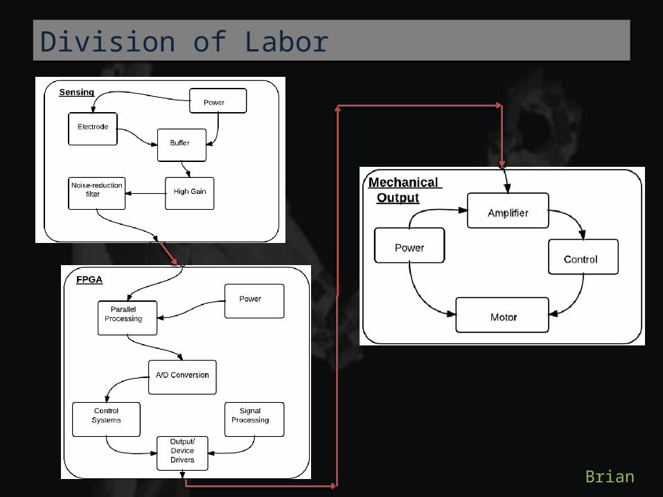
Signals - Brian/Elizabeth/Callie
Computer - Michael/Alex/Callie
Mechanical – Kerry/Brian/Elizabeth
Division of Labor
SignalingElectrode Design Brian/CallieAnalog Filtering Brian/Callie/ElizabethAnalog Signal Processing Brian/KerryNoise Reduction Callie/ElizabethSignal Amplifications Brian/ElizabethBuffer System ElizabethWireless Transmission Michael/Alex/KerryAnalog Digital Converter Michael/Alex
ComputerFPGA Michael/AlexDigital filtering Michael/AlexDevice Drivers Michael/AlexCode/Processing Michael/AlexInput/Output Module Michael/Alex/CallieControl System Michael/Alex/BrianPrinted Circuit Board Michael/Alex/Kerry
MechanicalAmplifier Kerry/Callie/ElizabethMechanical Power KerryMotor control Kerry/Alex/MichaelProsthetic Design Kerry/BrianWireless Interface Kerry/Michael/AlexPackaging Kerry/Elizabeth
Division of Labor
Brian
Division of Labor
Brian
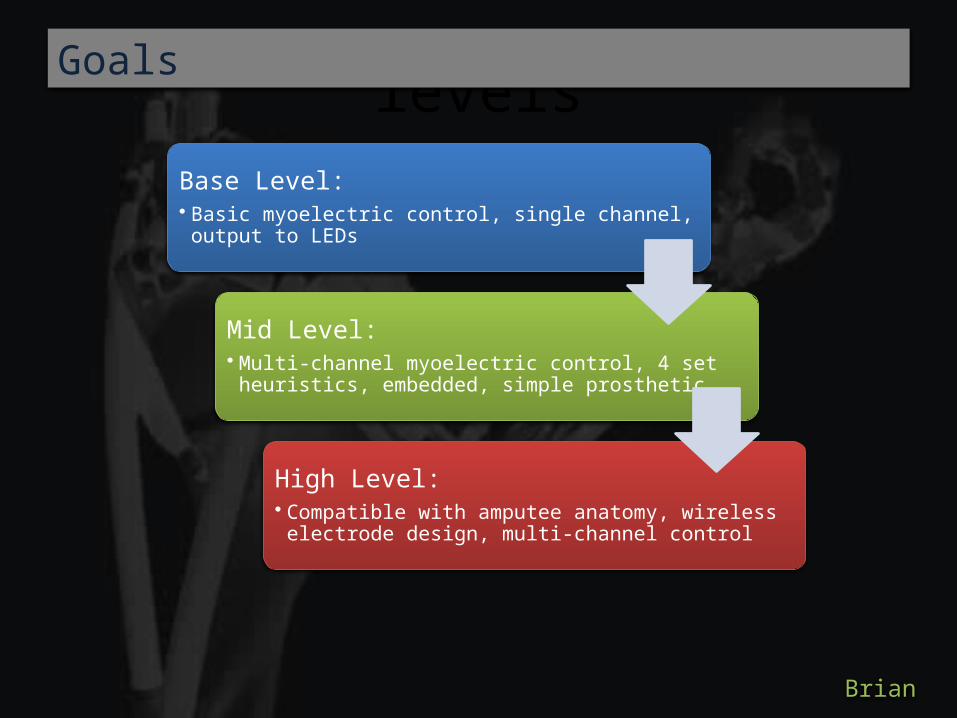
levelsGoals
Base Level:• Basic myoelectric control, single channel,
output to LEDs
Mid Level:• Multi-channel myoelectric control, 4 set
heuristics, embedded, simple prosthetic
High Level:• Compatible with amputee anatomy, wireless
electrode design, multi-channel control
Brian

Physiology
Action Potential (AP): the chemical depolarization of a muscle cell
Myoelectric Signal (MES): the resulting electrical activity of AP propagation through the muscle
Callie

Callie
Action Potential
Callie

Callie
AP Propagation
Callie
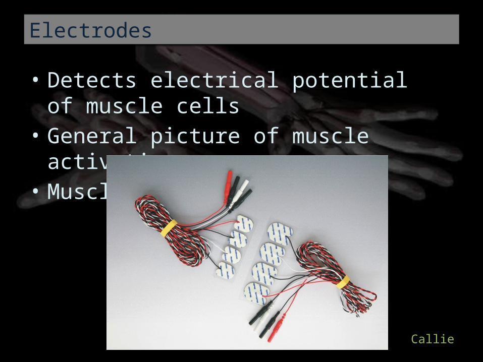
• Detects electrical potential of muscle cells• General picture of muscle activation• Muscle contraction AP
Callie
Electrodes
Callie

• 3 electrodes / signal• Differential amplifier between two electrodes• Reference electrode• Negates transducer noise• Maximize SNR
Callie
Bipolar Electrode Technique
Callie

Callie
Electrodes

• Impedances• Differentiation• Cross talk• Normalization• Dry vs. Gelled Electrodes• Fiber Density• Electrode Distances• Temperature• Physiological Conditions
Callie
Human Interface Concerns
Callie

• Repeat or new users• Response to impedance and normalization• Initialization system: detects min and max for
each muscle system based on electrode placement and differences between users
• Affects software base values
Callie
Calibration

Sensing Processing Output
Elizabeth
Signal Flowchart
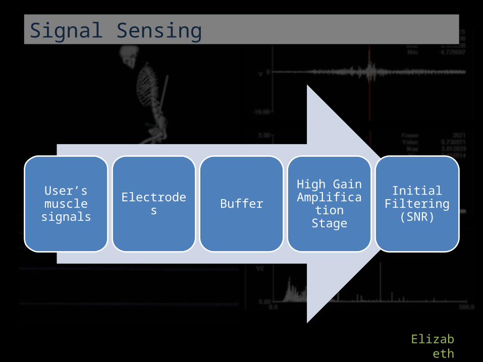
User’s muscle signals Electrodes Buffer
High Gain Amplification
Stage
Initial Filtering (SNR)
Elizabeth
Signal Sensing
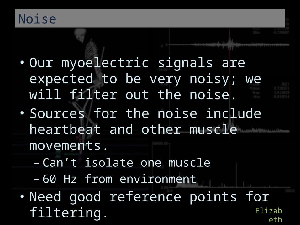
• Our myoelectric signals are expected to be very noisy; we will filter out the noise.
• Sources for the noise include heartbeat and other muscle movements.– Can’t isolate one muscle– 60 Hz from environment
• Need good reference points for filtering. • Want maximum signal-to-noise ratio (SNR) .
Elizabeth
Noise

• Need to ensure no current is able to travel through the electrode to the user.– Buffer circuit.– High impedance during the amplification stage– Lower power
• Wires dangling from subject– Wireless Implementation
Elizabeth
Safety Concerns

The Instrumentation Amplifier to the left, provides a buffer as well as high gain.
4-pole low pass filter
Elizabeth
Schematics For Signal Sensing

• Weak Signals– Group members are
working out to increase signal strength
– backup plan
• Broken Parts– Order backup parts– ESD safety
• Time– Work effectively as a
team
• Cost– Try not blowing chips
Elizabeth
Risks and Contingencies

Computing

Why FPGA?• Use signals to control a
variety of things.• Need an IC that can be
easily re-programmedfor different tasks.
• Can also re-purpose pins for extra analog to digital capabilities.
Michael
FPGA - Overview

•Myoelectric signal (~60 Hz)
Input
•Sample waveform
•Analyze digital waveform
Functionality
•Corresponding analog signal to control motor
Output
Michael
FPGA – Inputs/Outputs

• By using the re-programmable FPGA, we can control a variety of devices.
• Simple LEDs for testing.• We can output arm movement information to
a computer screen. If a robotic arm design falls through, we can try to design a virtual arm.
• Final goal: a semi-realistic robotic arm
Michael
FPGA Possibilities

• Most important FPGA task:– Determine what arm motion should occur based
on the myoelectric signals from multiple electrodes.• This is based on signal amplitude (minus the noise) and
also signal shape and approximate frequency.
Michael
FPGA Controls

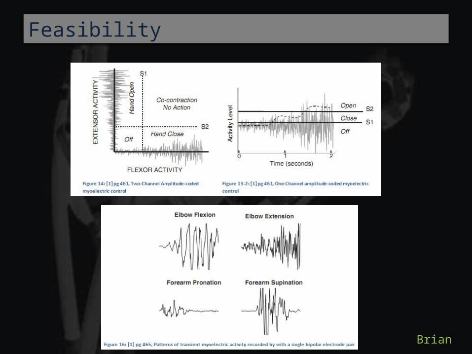
Some different signal shapes that we’ll have to take into consideration.
Michael
FPGA Controls

The speed of the arm movement can be deduced from the relative amplitude of the signals.
Michael
FPGA Controls

• We would also like to program some easy realistic arm movements using heuristic rules.
• These are educated decisions on how some motors should operate based on operations of other motors.
Michael
FPGA Controls

• It is highly likely that we will need to utilize frequency information of the myoelectric signals to make control decisions.
• On the FPGA we will need to implement some sort of FFT algorithm.
• We may need to utilize the Altera FFT MegaCore for this task (compatible with the Cyclone II FPGA).
Michael
More FPGA Information

• The entire project is dependent on successful sampling and digital processing of the myoelectric signal.
• Processing times: how long is the sampling and processing going to take?
• The FFT implementation could become incredibly complex. If frequency analysis falls through, we can try to glean all the information we need from the amplitudes of the different electrodes.
• We need to sample 5+ signals simultaneously. We may need to use multiple FPGA boards to achieve this (depending on how many A/D conversions we can squeeze out of one board.
Michael
FPGA – Risks and Pitfalls

• Even an ideal electromyogram will be around 6mV at its maximum amplitude.
• If we determine the movement type based on signal frequency, we will need a clean strong signal, to avoid mistaking noise for a waveform.
• Notch filtering should be avoided, so noise needs to be minimized.
Alexander
Risk Analysis

Alexander
Sampling Spectrum

• Noise reduction will be crucial– One way to reduce noise will be by using Bipolar
electrode arrangements– Essentially a pair of electrodes, which use sample,
then subtract out signals common to both with a differential amplifier
– The idea is to eliminate noise present at all points on the surface of the skin
Alexander
Risk Reduction

• Minimize lead lengths at all costs - even house the preamp on the sensor– This is important to minimize coupling with environmental
AC power, as well as control signals present in the device• It is important that pre-amplifier circuits have strong DC
component suppression circuitry.– Even a small DC component would drown out the signal
after amplification• There are DC components caused by factors involving
skin impedance and the chemical reactions between the skin and the electrode and gel.
Alexander
Signal Isolation

• It is very important that EMG pre-amplifiers have high input impedance.
• Input (i.e. source) impedance is typically less than 50 kOhms with gel electrodes and proper skin preparation
• To avoid input loading, the preamp needs a very high input impedance– 10s of MOhms for gel electrodes– 1000s kOhms for dry electrodes
Alexander
Optimizing the Usable Signal

• So lets talk for a moment about how all of this will be completed
• There are three main parts to this project– Sensing and Analog Signal Processing– Digital Signal Processing and Control Logic– Device Hardware
Alexander
Scheduling


Kerry
Prosthetic Arm
•FPGA-Processed analog signal
Input•Magnetic
energy spins the rotor
•Rotation speed dependent on amplitude and duration of signal
Functionality
•Motor swings the forearm appropriately
Output

Kerry
Prosthetic Arm (Higher Level Design)
Fore-arm twisting motion• Activated by pulse-
control• Would require a
specific, alternate signal from FPGA

Kerry
Prosthetic Arm (Higher Level Design)
Clamping motion• Also activated by
pulse-control• Would allow for
pinching and grasping actions

Kerry
Bill of Materials
Part Cost ($)
Mechanical Hardware 250
Surface electrodes and gel 50
Motors and drivers 150
PCB fab (2 revisions) 100
FPGA 50
Hardware: op-amps, wires, resistors 150
Wireless transmitters and receivers 175
Clamp 20
IC chips 60
Printing 130
Total 970

Questions ???
No?
GOOD.