brenna flaugher july 25-27,2006 directors review 1 the dark energy survey camera: decam 1.1...
TRANSCRIPT
Brenna Flaugher July 25-27,2006 Directors Review
1
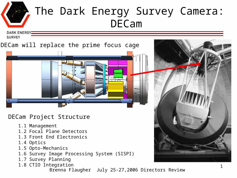
The Dark Energy Survey Camera: DECam
1.1 Management1.2 Focal Plane Detectors1.3 Front End Electronics1.4 Optics1.5 Opto-Mechanics1.6 Survey Image Processing System (SISPI)1.7 Survey Planning1.8 CTIO Integration
DECam will replace the prime focus cage
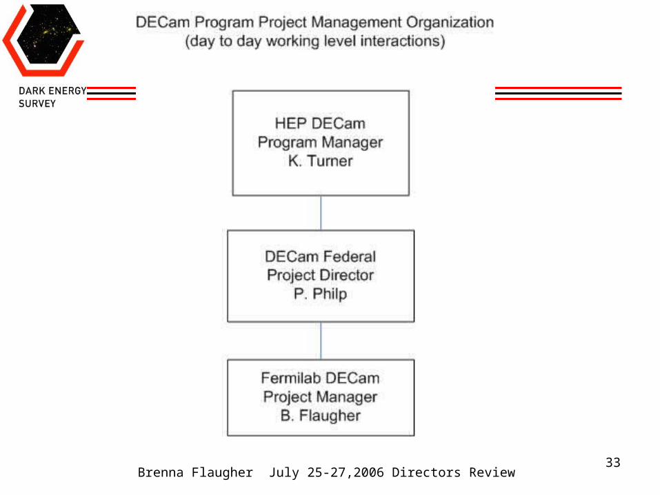
DECam Project Structure

Brenna Flaugher July 25-27,2006 Directors Review
2
DES: DECam
62 2kx4k Image CCDs: 520 MPix8 2kx2k focus, alignment CCDs4 2kx2 guide CCDs
DECam will be larger than any existing CCD camera
Each image:
~ 20 Galaxy clusters
~ 200,000 Galaxies
Each night ~ 300 GB
Entire survey ~ 1 PB
DES Focal Plane
OUTLINE of this talk•DECam
•project description•cost and schedule•critical paths
DECam provides simulated andreal data to the DES Data Management Project
Brenna Flaugher July 25-27,2006 Directors Review
3
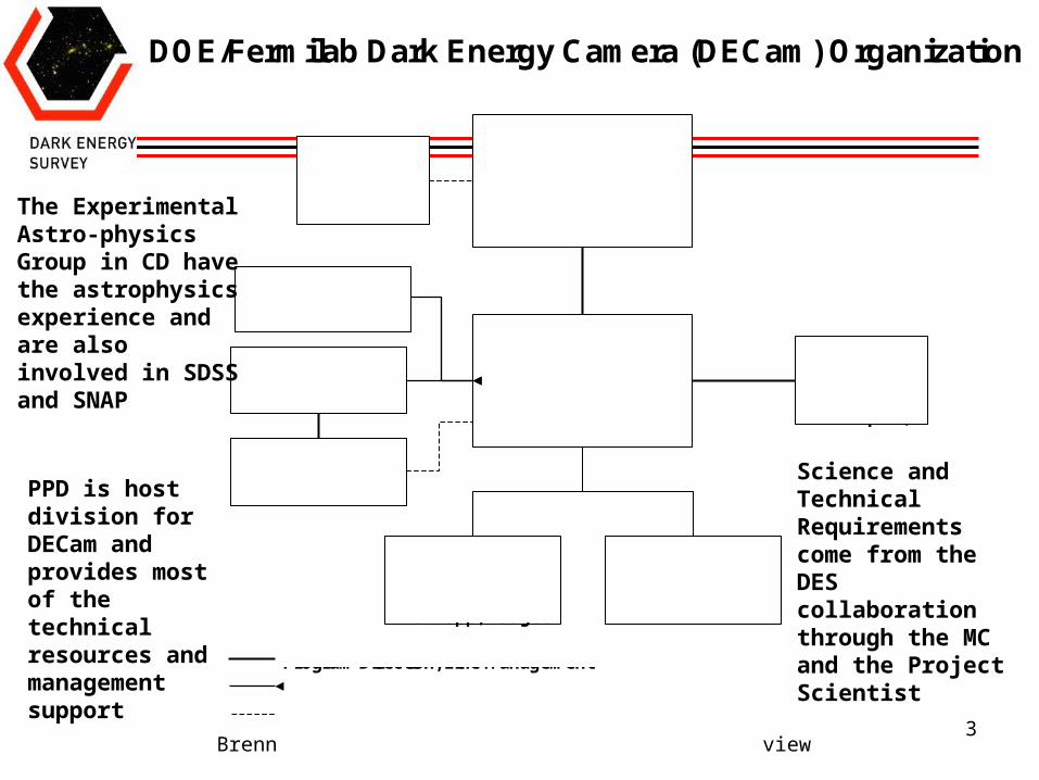
DOE/Fermilab Dark Energy Camera (DECam) Organization
FNAL DirectorP. Oddone
Associate Dir. For Research
H. Montgomery
DECAM ProjectB. Flaugher, PMT. Abbott, DPM
K.W. Merritt, DPMJ. Annis, Project
Scientist
Project Management
Group
DES Management CommitteeJ. Peoples,
Computing DivisionV. White, Head
Particle Physics Division
J. Strait, Head
ES&HM. Heflin, PPD SSO
Program Direction, Line Management
Resources
Advice
Project OfficeT.J. Sarlina,
ScheduleD. Knapp, Budget
Survey Instrument
Team
PPD is host division for DECam andprovides most of the technical resources and management support
The Experimental Astro-physics Group in CD have the astrophysics experience and are also involved in SDSS and SNAP
Science and Technical Requirements come from the DES collaborationthrough the MC and the Project Scientist
Brenna Flaugher July 25-27,2006 Directors Review
4
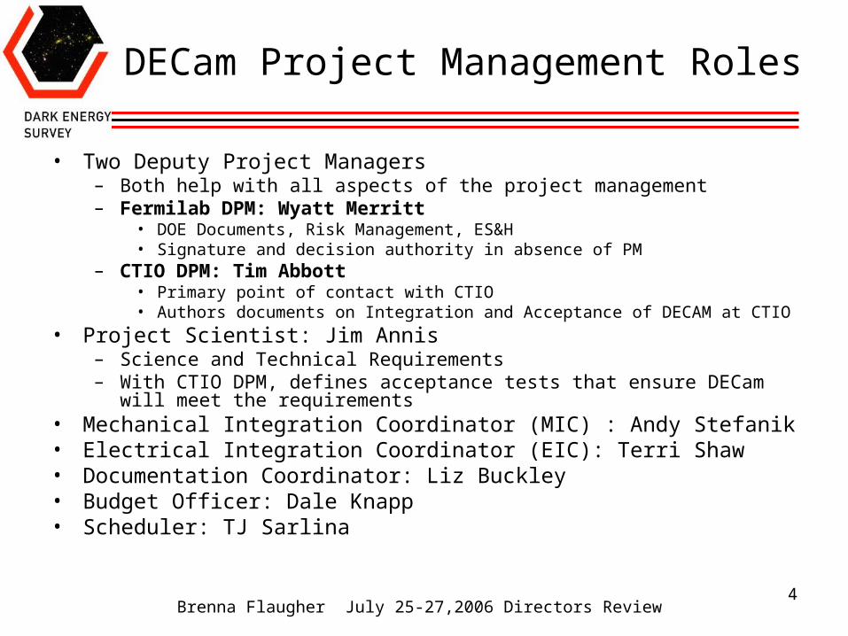
DECam Project Management Roles
• Two Deputy Project Managers– Both help with all aspects of the project management– Fermilab DPM: Wyatt Merritt
• DOE Documents, Risk Management, ES&H• Signature and decision authority in absence of PM
– CTIO DPM: Tim Abbott• Primary point of contact with CTIO• Authors documents on Integration and Acceptance of DECAM at CTIO
• Project Scientist: Jim Annis– Science and Technical Requirements – With CTIO DPM, defines acceptance tests that ensure DECam will meet the
requirements• Mechanical Integration Coordinator (MIC) : Andy Stefanik• Electrical Integration Coordinator (EIC): Terri Shaw• Documentation Coordinator: Liz Buckley• Budget Officer: Dale Knapp• Scheduler: TJ Sarlina
Brenna Flaugher July 25-27,2006 Directors Review
5
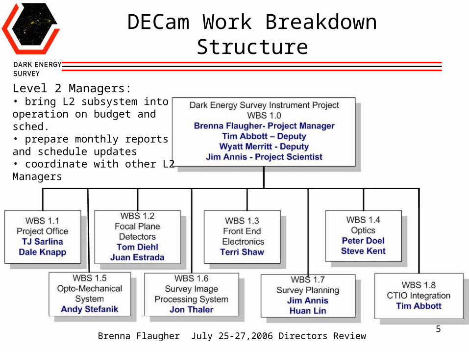
DECam Work Breakdown Structure
Level 2 Managers:• bring L2 subsystem into operation on budget and sched.• prepare monthly reports and schedule updates• coordinate with other L2 Managers
Brenna Flaugher July 25-27,2006 Directors Review
6
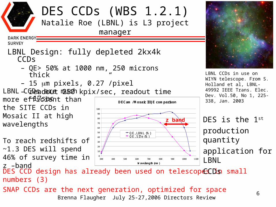
DES CCDs (WBS 1.2.1)Natalie Roe (LBNL) is L3 project manager
LBNL Design: fully depleted 2kx4k CCDs– QE> 50% at 1000 nm, 250 microns thick– 15 m pixels, 0.27”/pixel– readout 250 kpix/sec, readout time ~17sec
DECam / Mosaic II QE comparison
0
10
20
30
40
50
60
70
80
90
100
300 400 500 600 700 800 900 1000 1100
Wavelength (nm)
QE, LBNL (%)QE, SITe (%)
LBNL CCDs in use on WIYN telescope. From S. Holland et al, LBNL-49992 IEEE Trans. Elec. Dev. Vol.50, No 1, 225-338, Jan. 2003
LBNL CCDs are much more efficient than the SITE CCDs in Mosaic II at high wavelengths
To reach redshifts of ~1.3 DES will spend 46% of survey time in z –band
DES CCD design has already been used on telescopes in small numbers (3) SNAP CCDs are the next generation, optimized for space
DES is the 1st
production quantity
application for LBNL
CCDs
z band
Brenna Flaugher July 25-27,2006 Directors Review
7
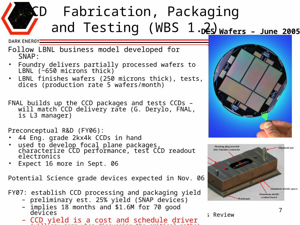
Follow LBNL business model developed for SNAP:• Foundry delivers partially processed wafers to LBNL (~650
microns thick)• LBNL finishes wafers (250 microns thick), tests, dices
(production rate 5 wafers/month)
FNAL builds up the CCD packages and tests CCDs – will match CCD delivery rate (G. Derylo, FNAL, is L3 manager)
Preconceptual R&D (FY06): • 44 Eng. grade 2kx4k CCDs in hand• used to develop focal plane packages, characterize CCD
performance, test CCD readout electronics• Expect 16 more in Sept. 06
Potential Science grade devices expected in Nov. 06
FY07: establish CCD processing and packaging yield– preliminary est. 25% yield (SNAP devices)– implies 18 months and $1.6M for 70 good devices– CCD yield is a cost and schedule driver (will say
more when discussing the critical paths)
CCD Fabrication, Packaging and Testing (WBS 1.2) DES Wafers – June 2005!
Brenna Flaugher July 25-27,2006 Directors Review
8
Front End Electronics WBS 1.3FNAL, Barcelona, Madrid, UIUC
• We chose the Monsoon CCD readout system developed by NOAO for our CCD testing and characterization efforts.– Monsoon: designed to be compact and low power for large mosaic cameras– 3 types of boards: Master Control board, Clock board and Acquisition board
• For the PF cage we need higher density:– Need a 12 channel instead of 8 channel Acquisition card (Fermilab)– Need more clock signals and buffers (Spain)– Master control board – convert optical link to S-link (Spain)– Compact, low noise power supplies (UIUC)
• Internal Collaboration review panel (led by Manel Martinez from Barcelona) investigated other options and this is their recommended path (their report is on the web)
• Spain and Fermilab are developing the new DES-Monsoon board designs• Spanish consortium plans to provide all the production FEE boards• Their proposal to their funding agencies was approved (~$1M). • UIUC is developing the thermally controlled housings for the crates and testing
prototype power supplies
Brenna Flaugher July 25-27,2006 Directors Review
9
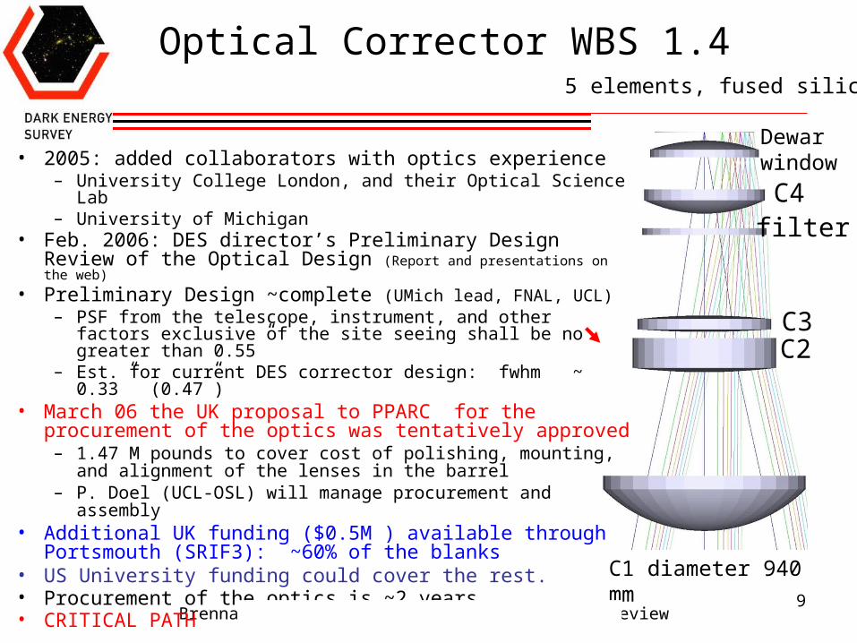
Optical Corrector WBS 1.4
• 2005: added collaborators with optics experience– University College London, and their Optical Science Lab– University of Michigan
• Feb. 2006: DES director’s Preliminary Design Review of the Optical Design (Report and presentations on the web)
• Preliminary Design ~complete (UMich lead, FNAL, UCL) – PSF from the telescope, instrument, and other factors
exclusive of the site seeing shall be no greater than 0.55”– Est. for current DES corrector design: fwhm ~ 0.33” (0.47”)
• March 06 the UK proposal to PPARC for the procurement of the optics was tentatively approved– 1.47 M pounds to cover cost of polishing, mounting, and
alignment of the lenses in the barrel– P. Doel (UCL-OSL) will manage procurement and assembly
• Additional UK funding ($0.5M ) available through Portsmouth (SRIF3): ~60% of the blanks
• US University funding could cover the rest.• Procurement of the optics is ~2 years • CRITICAL PATH
filter
Dewarwindow
C1 diameter 940 mm
C2C3
C4
5 elements, fused silica
Brenna Flaugher July 25-27,2006 Directors Review
10
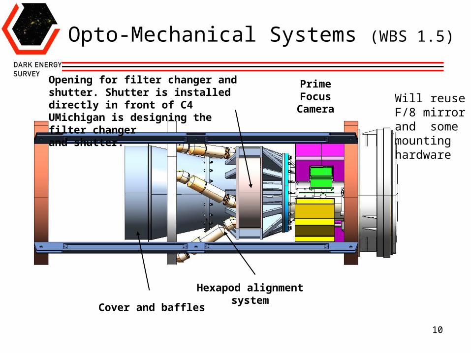
Opto-Mechanical Systems (WBS 1.5)
Opening for filter changer and shutter. Shutter is installed directly in front of C4UMichigan is designing the filter changer and shutter.
Cover and baffles
PrimeFocus
Camera
Hexapod alignmentsystem
Will reuseF/8 mirror and some mounting hardware
Brenna Flaugher July 25-27,2006 Directors Review
11
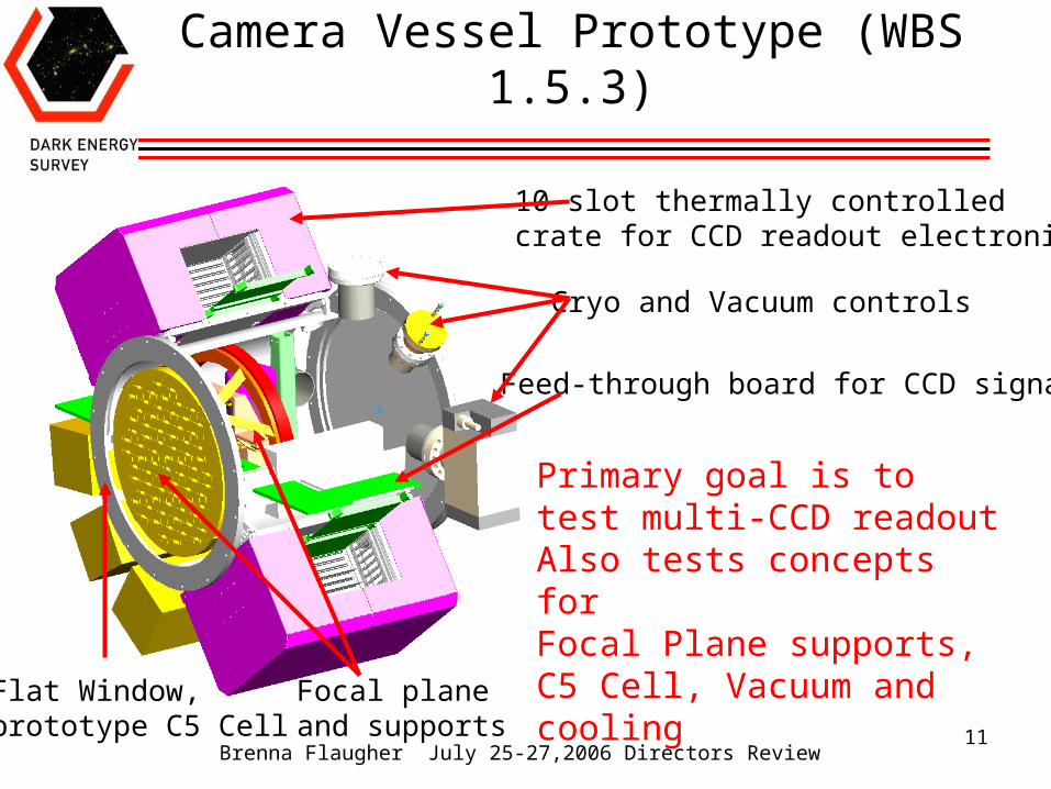
Camera Vessel Prototype (WBS 1.5.3)
10 slot thermally controlled crate for CCD readout electronics
Cryo and Vacuum controls
Focal planeand supports
Feed-through board for CCD signals
Primary goal is to test multi-CCD readoutAlso tests concepts for Focal Plane supports, C5 Cell, Vacuum and cooling
Flat Window, prototype C5 Cell
Brenna Flaugher July 25-27,2006 Directors Review
12
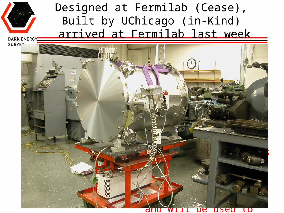
Designed at Fermilab (Cease), Built by UChicago (in-Kind) arrived at Fermilab last week
Cryo and Vacuum controls
Full size prototype is being built by U. Chicago. It will be ready for CCDs this summerand will be used to test multi-CCD readout

Brenna Flaugher July 25-27,2006 Directors Review
13
Survey Image System Process Integration (SISPI) WBS 1.6
CTIO will upgrade the Telescope Control System (TCS)
Data Management (DM): U. Illinois-Astro/NCSA
U Illinois-HEP (J. Thaler) is leading the SISPI development- similar to HEP-DAQ systems
Brenna Flaugher July 25-27,2006 Directors Review
14
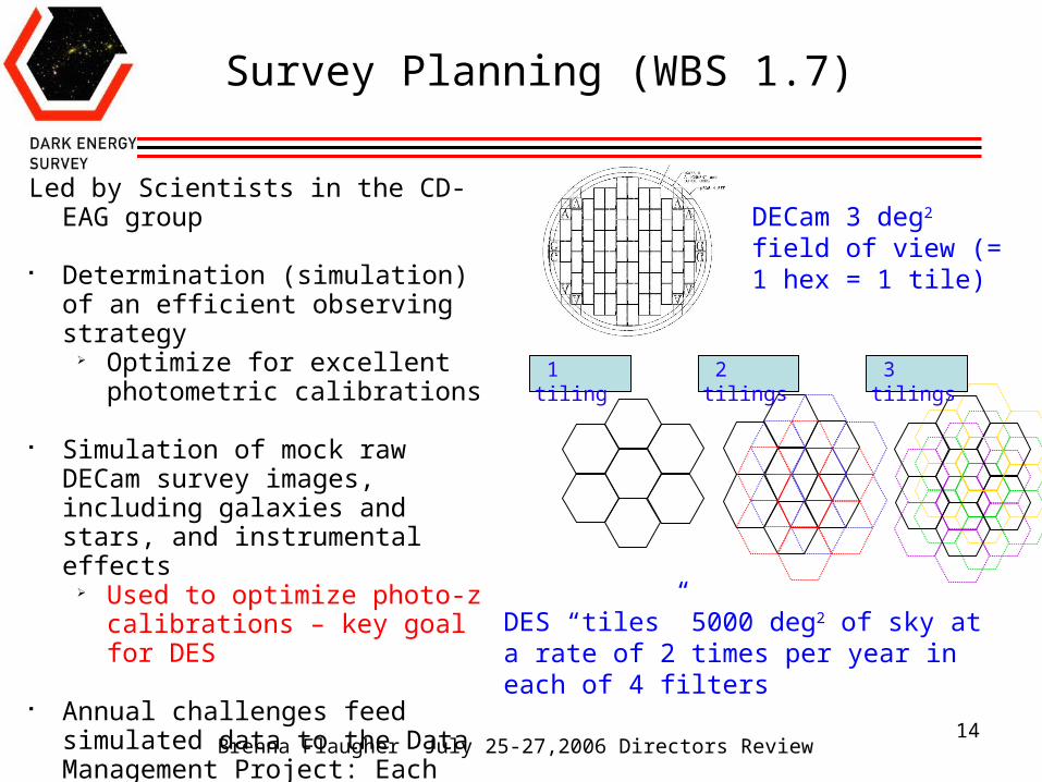
1 tiling 2 tilings 3 tilings
DECam 3 deg2 field of view (= 1 hex = 1 tile)
Survey Planning (WBS 1.7)
Led by Scientists in the CD-EAG group
Determination (simulation) of an efficient observing strategy
Optimize for excellent photometric calibrations
Simulation of mock raw DECam survey images, including galaxies and stars, and instrumental effects
Used to optimize photo-z calibrations – key goal for DES
Annual challenges feed simulated data to the Data Management Project: Each year the simulations grow in complexity and size
DES “tiles” 5000 deg2 of sky at a rate of 2 times per year in each of 4 filters
Brenna Flaugher July 25-27,2006 Directors Review
15
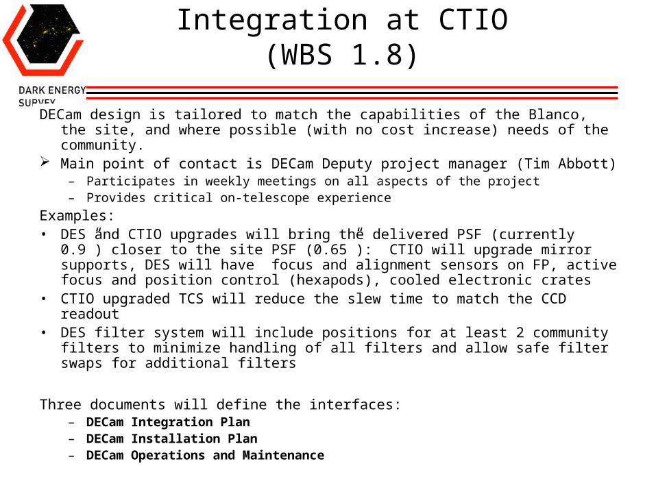
Integration at CTIO (WBS 1.8)
DECam design is tailored to match the capabilities of the Blanco, the site, and where possible (with no cost increase) needs of the community.
Main point of contact is DECam Deputy project manager (Tim Abbott)– Participates in weekly meetings on all aspects of the project – Provides critical on-telescope experience
Examples:• DES and CTIO upgrades will bring the delivered PSF (currently 0.9”) closer
to the site PSF (0.65”): CTIO will upgrade mirror supports, DES will have focus and alignment sensors on FP, active focus and position control (hexapods), cooled electronic crates
• CTIO upgraded TCS will reduce the slew time to match the CCD readout• DES filter system will include positions for at least 2 community filters to
minimize handling of all filters and allow safe filter swaps for additional filters
Three documents will define the interfaces:– DECam Integration Plan– DECam Installation Plan– DECam Operations and Maintenance
Brenna Flaugher July 25-27,2006 Directors Review
16
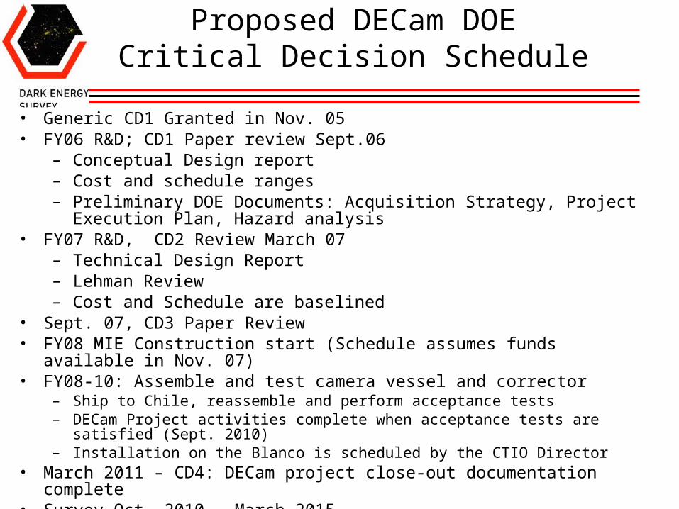
Proposed DECam DOE Critical Decision Schedule
• Generic CD1 Granted in Nov. 05• FY06 R&D; CD1 Paper review Sept.06
– Conceptual Design report– Cost and schedule ranges– Preliminary DOE Documents: Acquisition Strategy, Project Execution Plan,
Hazard analysis• FY07 R&D, CD2 Review March 07
– Technical Design Report– Lehman Review – Cost and Schedule are baselined
• Sept. 07, CD3 Paper Review• FY08 MIE Construction start (Schedule assumes funds available in Nov. 07)• FY08-10: Assemble and test camera vessel and corrector
– Ship to Chile, reassemble and perform acceptance tests– DECam Project activities complete when acceptance tests are satisfied (Sept. 2010)– Installation on the Blanco is scheduled by the CTIO Director
• March 2011 – CD4: DECam project close-out documentation complete• Survey Oct. 2010 - March 2015
Brenna Flaugher July 25-27,2006 Directors Review
17
DECam Cost and Schedule
• Cost and Schedule are captured in a Microsoft Project file• Will use Cobra to interface the schedule file to the Fermilab general ledger
and monitor project progress– matches budgeted cost of work performed to the schedule and to the progress
reported by the L2 mangers through monthly updates to the schedule file• Level 2 managers and engineers participate in the construction of the
schedule file• When estimating the cost and schedule the L2 managers were instructed to
be realistic – not overly conservative or aggressive – so contingency can be explicitly identified for both cost and schedule. Estimates are discussed and reviewed by Project management.
• Progress will be reported monthly to the ADR and the Federal Project Director through written reports and meetings of the Project Management Group
• Milestones of different levels (next slides) are used to define critical events and to monitor progress
Brenna Flaugher July 25-27,2006 Directors Review
18
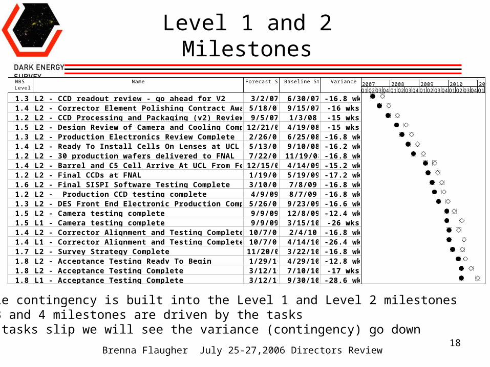
Level 1 and 2 Milestones
WBSLevel
Name Forecast Start Baseline Start Variance
1.3 L2 - CCD readout review - go ahead for V2 3/2/07 6/30/07 -16.8 wks1.4 L2 - Corrector Element Polishing Contract Awarded 5/18/07 9/15/07 -16 wks1.2 L2 - CCD Processing and Packaging (v2) Review Complete 9/5/07 1/3/08 -15 wks1.5 L2 - Design Review of Camera and Cooling Complete 12/21/07 4/19/08 -15 wks1.3 L2 - Production Electronics Review Complete 2/26/08 6/25/08 -16.8 wks1.4 L2 - Ready To Install Cells On Lenses at UCL 5/13/08 9/10/08 -16.2 wks1.2 L2 - 30 production wafers delivered to FNAL 7/22/08 11/19/08 -16.8 wks1.4 L2 - Barrel and C5 Cell Arrive At UCL From Fermilab 12/15/08 4/14/09 -15.2 wks1.2 L2 - Final CCDs at FNAL 1/19/09 5/19/09 -17.2 wks1.6 L2 - Final SISPI Software Testing Complete 3/10/09 7/8/09 -16.8 wks1.2 L2 - Production CCD testing complete 4/9/09 8/7/09 -16.8 wks1.3 L2 - DES Front End Electronic Production Complete 5/26/09 9/23/09 -16.6 wks1.5 L2 - Camera testing complete 9/9/09 12/8/09 -12.4 wks1.5 L1 - Camera testing complete 9/9/09 3/15/10 -26 wks1.4 L2 - Corrector Alignment and Testing Complete 10/7/09 2/4/10 -16.8 wks1.4 L1 - Corrector Alignment and Testing Complete 10/7/09 4/14/10 -26.4 wks1.7 L2 - Survey Strategy Complete 11/20/09 3/22/10 -16.8 wks1.8 L2 - Acceptance Testing Ready To Begin 1/29/10 4/29/10 -12.8 wks1.8 L2 - Acceptance Testing Complete 3/12/10 7/10/10 -17 wks1.8 L1 - Acceptance Testing Complete 3/12/10 9/30/10 -28.6 wks
Q1Q2Q3Q4 Q1Q2Q3Q4Q1Q2Q3Q4Q1Q2Q3Q4Q1Q22007 2008 2009 2010 2011
Schedule contingency is built into the Level 1 and Level 2 milestonesLevel 3 and 4 milestones are driven by the tasksIf the tasks slip we will see the variance (contingency) go down
Brenna Flaugher July 25-27,2006 Directors Review
19
Change Control: Schedule
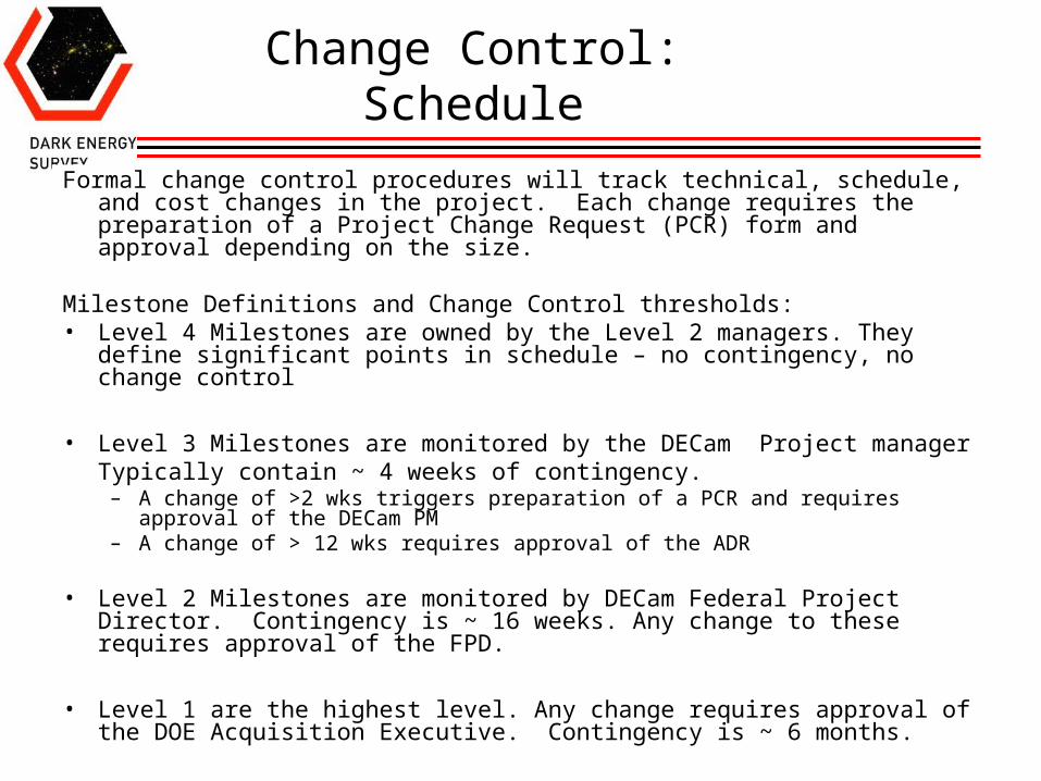
Formal change control procedures will track technical, schedule, and cost changes in the project. Each change requires the preparation of a Project Change Request (PCR) form and approval depending on the size.
Milestone Definitions and Change Control thresholds:• Level 4 Milestones are owned by the Level 2 managers. They define
significant points in schedule – no contingency, no change control
• Level 3 Milestones are monitored by the DECam Project manager Typically contain ~ 4 weeks of contingency.
– A change of >2 wks triggers preparation of a PCR and requires approval of the DECam PM
– A change of > 12 wks requires approval of the ADR
• Level 2 Milestones are monitored by DECam Federal Project Director. Contingency is ~ 16 weeks. Any change to these requires approval of the FPD.
• Level 1 are the highest level. Any change requires approval of the DOE Acquisition Executive. Contingency is ~ 6 months.
Brenna Flaugher July 25-27,2006 Directors Review
20
Cost
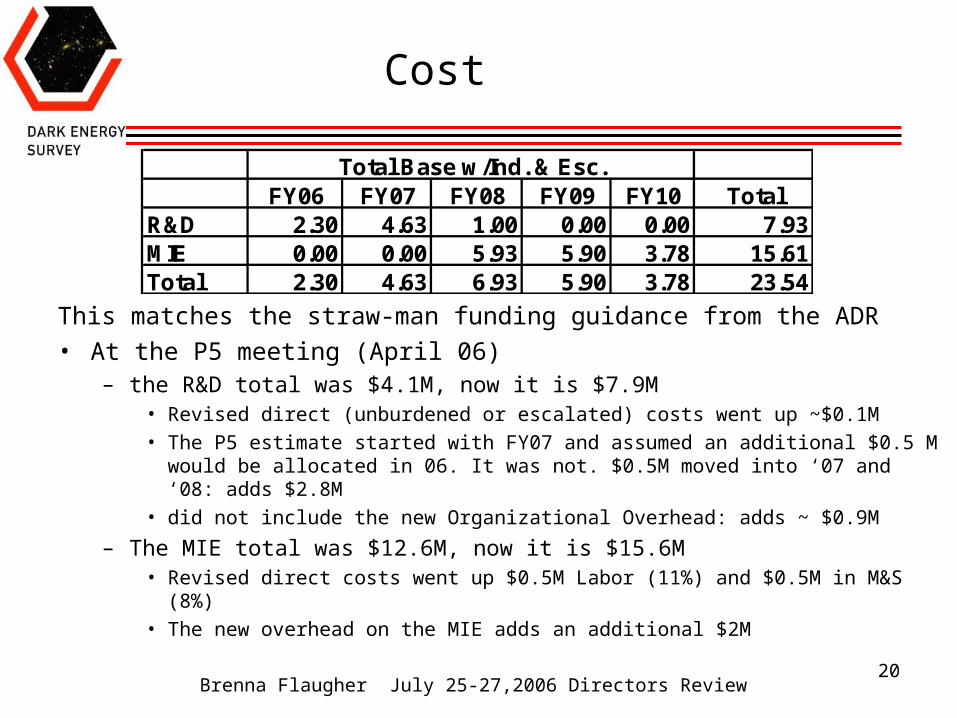
This matches the straw-man funding guidance from the ADR• At the P5 meeting (April 06)
– the R&D total was $4.1M, now it is $7.9M• Revised direct (unburdened or escalated) costs went up ~$0.1M• The P5 estimate started with FY07 and assumed an additional $0.5 M would be
allocated in 06. It was not. $0.5M moved into ‘07 and ‘08: adds $2.8M• did not include the new Organizational Overhead: adds ~ $0.9M
– The MIE total was $12.6M, now it is $15.6M• Revised direct costs went up $0.5M Labor (11%) and $0.5M in M&S (8%)• The new overhead on the MIE adds an additional $2M
FY06 FY07 FY08 FY09 FY10 TotalR&D 2.30 4.63 1.00 0.00 0.00 7.93MIE 0.00 0.00 5.93 5.90 3.78 15.61Total 2.30 4.63 6.93 5.90 3.78 23.54
Total Base w/Ind. & Esc.
Brenna Flaugher July 25-27,2006 Directors Review
21
Cost Contingency
• MSP Schedule file contains columns to indicate a contingency factor separately for the M&S and the labor cost
• Typical contingency assigned to each task:– Labor is 50%
– M&S is 40%.
• If we have a reliable quote or direct experience the M&S contingency factor is 20%
• For the CCDs we have 20% on the CCD fabrication (LBNL and Dalsa costs have been right on so far) and also have included the cost of procurement and processing of an additional 24 wafer lot ($485k)
• As the risk analysis becomes more sophisticated, the factors will be adjusted to reflect the risks
• The contingency on each task is calculated in the MSP file and included in the MIE cost of the project. Total is ~ 35%

Brenna Flaugher July 25-27,2006 Directors Review
22
Cost Range
• For DOE Critical Decision 1 we need a cost and schedule range • The range should bracket the estimated cost and schedule of the project• Further analysis and feedback between now and CD2 will transform the
ranges into the project baseline cost and schedule for the CD2 Review (~March 07)
How we derived the ranges:• For the high end we assumed we have to repeat FY09. This would add
$6M to the MIE: $29.5M• For the low end we assumed we only need half the contingency (for
example if we could determine the CCD yield was 50% rather than 25%): The DOE MIE would be $20.4M
• For the schedule range the earliest finish from the schedule without contingency (March 2010) . For the high end we add one year to the earliest finish (March 2011)
• This will be a topic for discussion in the management breakout
Brenna Flaugher July 25-27,2006 Directors Review
23
Change Control: Technical and Cost
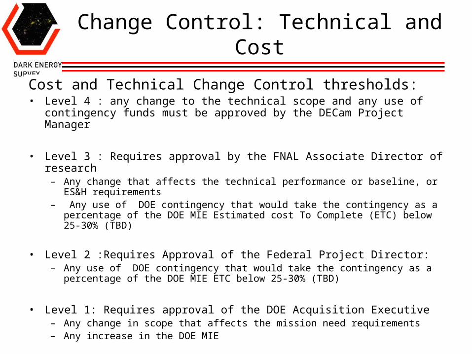
Cost and Technical Change Control thresholds:• Level 4 : any change to the technical scope and any use of contingency
funds must be approved by the DECam Project Manager
• Level 3 : Requires approval by the FNAL Associate Director of research– Any change that affects the technical performance or baseline, or ES&H
requirements– Any use of DOE contingency that would take the contingency as a percentage
of the DOE MIE Estimated cost To Complete (ETC) below 25-30% (TBD)
• Level 2 :Requires Approval of the Federal Project Director:– Any use of DOE contingency that would take the contingency as a percentage of
the DOE MIE ETC below 25-30% (TBD)
• Level 1: Requires approval of the DOE Acquisition Executive– Any change in scope that affects the mission need requirements – Any increase in the DOE MIE

Brenna Flaugher July 25-27,2006 Directors Review
24
DECam critical paths: CCDs & Optics
CCDs:• LBNL can deliver CCDs at a rate of 20/month after 3 month
startup• We need 70 CCDs for the FP including spares• Preliminary yield estimate of 25% implies ~18 months • Cost is ~$23k/wafer, 25% yield implies $1.6M• Construction start of Oct. 07 implies last CCD is finished March
’09• Install last CCD and test full camera ~ 2 months• Ready to ship to Chile ~ Sept. 09• Level 2 Milestone on March 2010 includes 6 months contingency
Optics:• Blanks ~ $0.9M , 8 month delivery• Polishing ~ $1.5M, 18 month delivery• Assembly and alignment into corrector ~ 6 months• Ready to ship to Chile ~ 2.75 yrs after procurement begins • Feb. 07 → Oct. 09 delivery• Level 2 Milestone on April 2010 includes 6 months contingency
Brenna Flaugher July 25-27,2006 Directors Review
25
CCD procurement and Yield
• CCDs are ordered from Dalsa in Lots of 24 wafers• 3 out of the 24 are used by Dalsa to control/monitor the processing.
These are finished at Dalsa, functional but 650 microns thick• Testing occurs at multiple stages
– Dalsa tests control wafers; provides first estimate of success
– LBNL tests the control wafers on a cold probe station (-45 C)• Can find bad RO channels, and other gross effects • estimate of the cosmetic defects (some will freeze out)
– After thinning and processing at LBNL, cold probing of the 2kx4k devices provides preliminary estimate of yield and is used to determine the order of packaging at FNAL
– After packaging, CCDs are tested at FNAL at operating temp. (-100C)
(see next talk)
Brenna Flaugher July 25-27,2006 Directors Review
26
CCD procurement
• Yield can vary between lots but is fairly uniform within a lot• When Dalsa gets started – processing can proceed quickly (8-12
weeks) but sometimes we are not their highest priority• Processing at LBNL takes 12 weeks for the first 5 wafers and then can
sustain a rate of 5 wafers/month.• Processing at Dalsa is ~ 5k/wafer, processing at LBNL is $17.5k/waferR&D:
– Develop a mask with four 2kx4k CCDs to minimize processing costs– Order 1 Lot for development of packaging and testing procedures: Lot 1– Order 4 lots of 24 wafers with potential for focal plane CCDs (Lots 2A-D)– Process 5 wafers per lot at LBNL to determine Lot yield
Production (once MIE funds are approved):– Order another lot if yield is < 25%– Initiate processing at LBNL of remaining wafers (schedule assumes Nov
07 start) ~18 months
Brenna Flaugher July 25-27,2006 Directors Review
27
R&D program status
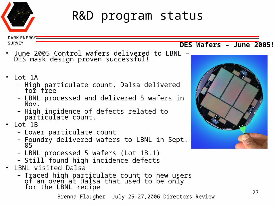
• June 2005 Control wafers delivered to LBNL – DES mask design proven successful!
• Lot 1A – High particulate count, Dalsa delivered for free– LBNL processed and delivered 5 wafers in Nov.– High incidence of defects related to particulate
count. • Lot 1B
– Lower particulate count– Foundry delivered wafers to LBNL in Sept. 05– LBNL processed 5 wafers (Lot 1B.1)– Still found high incidence defects
• LBNL visited Dalsa– Traced high particulate count to new users of an
oven at Dalsa that used to be only for the LBNL recipe
DES Wafers – June 2005!
Brenna Flaugher July 25-27,2006 Directors Review
28
CCD Fabrication Update
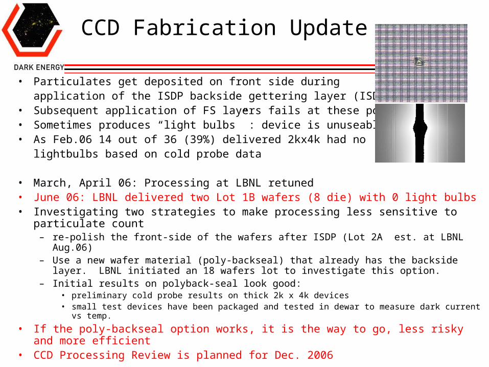
• Particulates get deposited on front side during application of the ISDP backside gettering layer (ISDP)
• Subsequent application of FS layers fails at these points• Sometimes produces “light bulbs” : device is unuseable• As Feb.06 14 out of 36 (39%) delivered 2kx4k had no
lightbulbs based on cold probe data
• March, April 06: Processing at LBNL retuned• June 06: LBNL delivered two Lot 1B wafers (8 die) with 0 light bulbs• Investigating two strategies to make processing less sensitive to particulate count
– re-polish the front-side of the wafers after ISDP (Lot 2A est. at LBNL Aug.06)– Use a new wafer material (poly-backseal) that already has the backside layer. LBNL
initiated an 18 wafers lot to investigate this option.– Initial results on polyback-seal look good:
• preliminary cold probe results on thick 2k x 4k devices• small test devices have been packaged and tested in dewar to measure dark current vs temp.
• If the poly-backseal option works, it is the way to go, less risky and more efficient• CCD Processing Review is planned for Dec. 2006
Brenna Flaugher July 25-27,2006 Directors Review
29
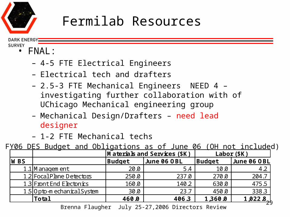
Fermilab Resources
• FNAL:– 4-5 FTE Electrical Engineers – Electrical tech and drafters– 2.5-3 FTE Mechanical Engineers NEED 4 – investigating
further collaboration with of UChicago Mechanical engineering group
– Mechanical Design/Drafters – need lead designer– 1-2 FTE Mechanical techs
Materials and Services ($K) Labor ($K)WBS Budget June 06 OBL Budget June 06 OBL
1.1 Management 20.0 5.4 10.0 4.21.2 Focal Plane Detectors 250.0 237.0 270.0 204.71.3 Front End Electonics 160.0 140.2 630.0 475.51.5 Opto-mechanical System 30.0 23.7 450.0 338.3
Total 460.0 406.3 1,360.0 1,022.8
FY06 DES Budget and Obligations as of June 06 (OH not included)
Brenna Flaugher July 25-27,2006 Directors Review
30
In-Kind Contributions
• Memoranda of Understanding (MOU) between each institution and Fermilab define overall contribution to DECam and institutional roles
• Annual Statements of Work (SOW) specify – funding and commitments for the next Fiscal Year, – the in-kind contributions of the institution to the DECam project, – the resources provided by Fermilab to the institution, – the responsibilities of key personnel from Fermilab and the institution, – schedule and milestones for completion of the tasks.
• The collaborating institution intend to cover the full cost of the components that are identified as in-kind contributions.
• Each institutional proposal includes contingency • Proposed changes to the in-kind deliverables will be reviewed by the DES
Project Director and DCam Project Scientist and Manager• If the technical performance, cost or schedule changes affects the DECam
L2 milestones it will be brought to the attention of the PMG and the Change Control Board for action and the institutional DECam MOU will be revised.
• Collaborations also have identified contributions to the DECam “Common Fund” these contributions will be used through consultation of the DES PD, the DECam PM and the relevant Institution and can function as additional contingency on the institutional in-kind contribution.
Brenna Flaugher July 25-27,2006 Directors Review
31
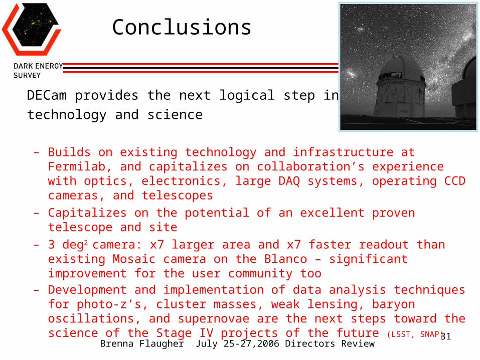
Conclusions
DECam provides the next logical step in both
technology and science
– Builds on existing technology and infrastructure at Fermilab, and capitalizes on collaboration’s experience with optics, electronics, large DAQ systems, operating CCD cameras, and telescopes
– Capitalizes on the potential of an excellent proven telescope and site
– 3 deg2 camera: x7 larger area and x7 faster readout than existing Mosaic camera on the Blanco – significant improvement for the user community too
– Development and implementation of data analysis techniques for photo-z’s, cluster masses, weak lensing, baryon oscillations, and supernovae are the next steps toward the science of the Stage IV projects of the future (LSST, SNAP)
Brenna Flaugher July 25-27,2006 Directors Review
32
EXTRAs
Brenna Flaugher July 25-27,2006 Directors Review
33

Brenna Flaugher July 25-27,2006 Directors Review
34
Brenna Flaugher July 25-27,2006 Directors Review
35
Change Control
• The July 2004 proposal serves as the reference design of DECam
• Since then we have developed – A separate Science and Technical requirements document that
contains a more complete and detailed description– A conceptual design report which contains updated description
of the science projections and an undated design for DECam that includes the design and experience in the last 2 years
• The Science Requirements document states the requirements of DECam and is under change control
• DECam design also responds to the needs of the community
• The Fermilab PMG serves as the change control board
Brenna Flaugher July 25-27,2006 Directors Review
36
End Game
• C5 Cell is fit to Barrel before barrel is shipped to UCL• Corrector is shipped directly to CTIO from UCL• Camera goes from FNAL to CTIO• Will have a second barrel and a simulator of the top end
flip ring at FNAL for testing the hexapod, the cooling and cable routing, Filter changer and shutter
• At CTIO the camera and corrector will be reassembled and tested in the clean room on the Mountain.
• Acceptances tests on the floor at CTIO define the end of the DECam project.
• CTIO Director decides when to disassemble the telescope and install DES.