breathing simulator of workers for respirator performance test · breathing simulator of workers...
TRANSCRIPT
Breathing simulator of workers for respirator performance test
Hisashi YUASA1, 2, Mikio KUMITA1*, Takeshi HONDA2, Kazushi KIMURA2, Kosuke NOZAKI2, Hitoshi EMI1, 2 and Yoshio OTANI1
1Kanazawa University, Japan2Koken Ltd., Japan
Received April 9, 2014 and accepted October 20, 2014 Published online in J-STAGE November 8, 2014
Abstract: Breathing machines are widely used to evaluate respirator performance but they are capable of generating only limited air flow patterns, such as, sine, triangular and square waves. In order to evaluate the respirator performance in practical use, it is desirable to test the respirator using the actual breathing patterns of wearers. However, it has been a difficult task for a breathing machine to generate such complicated flow patterns, since the human respiratory volume changes depending on the human activities and workload. In this study, we have developed an electrome-chanical breathing simulator and a respiration sampling device to record and reproduce worker’s respiration. It is capable of generating various flow patterns by inputting breathing pattern signals recorded by a computer, as well as the fixed air flow patterns. The device is equipped with a self-control program to compensate the difference in inhalation and exhalation volume and the measurement errors on the breathing flow rate. The system was successfully applied to record the breathing patterns of workers engaging in welding and reproduced the breathing patterns.
Key words: Breathing simulator, Respirator, Minute volume, Breathing pattern, Respirator test
Introduction
Respirators have been used to protect wearers from inhaling hazardous materials, and its performance is greatly affected by the wearers’ breathing conditions. The breathing is intensified several times or more compared to that of resting, and the features of breathings are sig-nificantly influenced by many factors; gender, body size, load, physical movement, and talking as well as the other environmental conditions1–3). In contrast, the certification test of respirators has been carried out using a constant air flow rate and/or a mechanically generated cyclic flow
with sine waveform (e.g., Federal regulation for certifying air-purifying particulate respirators: 42 CFR 84, Japanese Standard for dust respirators). These flow patterns may provide relative comparison of individual respirators by measuring the performance under the same breathing conditions. However, it is difficult for these certification tests to reflect the performance of respirators in actual use because the breathing patterns may vary to a large extent depending on the work load. Moreover, advances in recent technology have enabled the development of more sophisticated respirators, such as a PAPR which synchronizes the air supply with the wearer’s breathing intensity, and a respirator with a gas sensor for indicating the end of service life of canisters. The effectiveness of these devices must be evaluated with the actual breathing patterns of wearers. Therefore it is important to evaluate
*To whom correspondence should be addressed.E-mail: [email protected]
©2015 National Institute of Occupational Safety and Health
Industrial Health 2015, 53, 124–131 Original Article
BREATHING SIMULATOR FOR RESPIRATOR PERFORMANCE TEST 125
the respirator performance as a function of the breathing pattern which simulates typical usage conditions. In order to assess the practical performance of respirators, the par-ticle concentration in/out respirators which was worn by volunteers and workers were measured in laboratories and workplaces4–7). Subject test, however, is not able to com-pare various masks under the same breathing condition, as it is quite difficult for repeating the same breathing pat-tern. Furthermore it is not possible to conduct the subject test with hazardous substances suspended in air. For these reasons, breathing machines have been used to evalu-ate respirators, filters and cartridges in laboratories8–13). Some studies reported breathing simulators or automated breathing and metabolic simulators which could generate more complex breathing patterns14–19). However they did not attempt to reproduce actual worker’s breathing pattern sampled at workplace. While a few articles addressed a sampling device for human respiration and recorded breathing patterns of workers, they did not reproduce the respiration patterns with breathing simulators20, 21).
Authors studied the breathing recording unit which was adoptable at a workplace, and the recorded breathing patterns were used to reproduce with the breathing simula-tor22–24). This system can be used to evaluate the respirator performances under simulated actual breathing condi-tions in laboratories, such as filter efficiency, adsorption capacity, breathing resistance, respirator fit, service life of filter cartridges and batteries, demanded air pressure and volume, and sensor responsibility22, 24, 25). These perfor-mances cannot be obtained with fixed breathing patterns.
Conventional simulators had difficulty in reproducing repeated breathing patterns from the recorded breathing patterns because the differences between inspiration and exhalation volume per breath would eventually cause mal-function of piston movements of breathing simulator. This paper reports the detail of our newly developed breath-
ing simulator with an improved feature for reproducing complicated flow patterns for a longer period of time so that we can apply it for testing respirators even under dust loaded conditions. The accuracy of system was confirmed through the comparison of recorded and reproduced air flow patterns of welding workers.
System of the Breathing Simulator
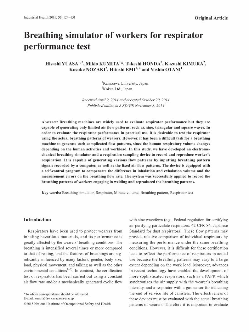
System and specifications of the developed breathing simulator are shown in Fig. 1 and Table 1. The system is mainly composed of a servo cylinder and its control-ler (CYA150, Shinto, Japan), a wave amplifier (2711A, Pragmatic Instruments, USA), and two air cylinders (10A-6, Taiyo, Japan). Use of two air cylinders enable us to test two samples simultaneously and to perform more compli-able test such as measurement of respirator dead space using carbon dioxide gas. The torque of servo cylinder is 2.92 kN, the stroke speed is 300 mm/s and the stroke length is 250 mm. The air cylinders’ rods are mechanically connected to the servo cylinder, so the strokes of these cylinders are harmonized. The stroke is controlled within the accuracy of 0.01 mm displacement to reproduce small
Fig. 1. Basic concept of breathing flow reproduction system.
Table 1. Specifications of breathing simulator
Breathing frequency per minute (cycles/min)
0–300
Maximum cylinder stroke (mm) 250Maximum cylinder speed (mm/s) 300Tidal volume of one breath (L/cycle) 0–6Maximum minute volume of breathing simulator (L/min)
180
Reproductive breathing waveform (3 modes)
1. Sine, Triangle, Square 2. Arbitrary 3. Synchronized-control with a human respiration
H YUASA et al.126
Industrial Health 2015, 53, 124–131
changes in complex breathing patterns. The diameters of the two air cylinders are 125 mm. This makes 6 L/stroke, and the frequency is 30 cycles/min at the maximum stroke, corresponding to 180 L/min in minute volume. This complies with any ventilation conditions employed by the certification tests for respirators in many countries, such as the US, EU, Japan, Korea and China.
The breathing simulator can be operated in 3 modes to produce breathing air flows (Table 1). In the first mode of generating cyclic flow with a given breathing pattern (sine, triangular, square, etc.), inspiration volume and frequency, the necessary data are inputted using a data setter. In this mode, the program for controlling the motion of servo cylinder automatically calculates the cylinder position as a function of time. In the second mode, arbitrary flow patterns created by PC or recorded worker’s breathing patterns can be generated. The breathing data are sent to the servo controller via an amplifier. In the third mode, the breathing simulator duplicates the human’s breathing pat-tern in real-time. The output of a spirometer is sent to the servo controller via a DC convertor.
Generation and Control of Airflow Pattern with the Breathing Simulator
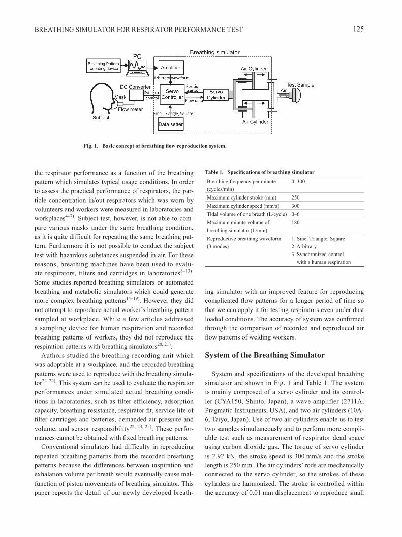
Figure 2 shows the volumetric flow rate of respiratory air at time t, Vt for a sinusoidal function:
Vt=Vmax sin (2πt/τ) (1)
where Vmax is the peak flow rate and τ is the cycle time of a single breath. The breathing pattern consists of inspiration and expiration. The tidal volume, Vi, is equal to the area either below or above the base line Vt=0. Vmax is related to the average volumetric flow rate, Vave, by Equation (2).
Vmax=πVave=πVi F (2)
where Vave is the minute volume of inspired air, which is equal to the product of tidal volume, Vi, and the number of breathings per minute, F.
When a piston (reciprocal pump) is used to generate the airflow, Vi is equal to the product of cylinder stroke, L, and the cross-sectional area of cylinder, A. Eq. (1) is now given by Equation (3) for the piston-generated airflow.
Vt =(πAFL) sin (2πFt) (3)
Sinusoidal air flows with arbitrary Vi and F are generated by controlling the piston movement and the stroke accord-ing to Eq. (3). Since the position of piston, x, is related to Vt by Vt =Adx/dt, x is given by the following equation.
x= − (L/2) cos (2πFt) (4)
Because the breathing pattern of a human changes in complicated manner from breath to breath, the inhaled air volume is not always the same as the exhaled air volume, and moreover, the recorded breathing patterns are always accompanied with measurement errors. The errors in measuring breathing flow rate could be caused by many factors, such as measuring principle of device, tempera-ture, humidity, humans, recording intervals. The difference in inspired and exhaled air volume and the measurement error in air flow rate were apt to accumulate during the reproduction of breathing patterns, which eventually resulted in malfunction of servo cylinder movements. As a consequence, the piston no longer generated the breathing patterns. Therefore, in the present work, the position of piston was moved back to the null position if the accu-mulated displacement of piston position exceeds a given allowance of displacement.
The flowchart of piston movement control of breathing simulator is shown in Fig. 3. Prior to sending the control voltage, (vin)i, to the servo cylinder, the program judges whether the correction is required to bring back the center of piston stroke to the original position. S is the sum of piston displacements. If the breathing pattern is completely symmetric during a single breath, the sum of piston dis-placements is zero. However this is not the case because the inhalation flow pattern is not symmetric to the exhala-tion flow pattern. If the accumulated piston displacements, S, is not within the allowance, Z, the control voltage, (vin)i, is multiplied by either a or –a depending on the bias of piston stroke from the original position. After the piston movements, the piston displacements, xi, is detected at a given interval, and store the series of displacements in the memory. The program calculates the sum of piston displacements for the last M consecutive data and that for
Fig. 2. Example of a breathing pattern (sinusoidal).

BREATHING SIMULATOR FOR RESPIRATOR PERFORMANCE TEST 127
last 2M to M+1 data as well as S. When the piston position correction is on and if the absolute value of the sum of dis-placements for the last M consecutive data is smaller than that for last 2M to M+1 consecutive data, the correction of piston movements is terminated by setting S=0.
Figure 4 shows how the correction works in generating repeated breathing patterns. In this figure, the waveform shown by bold line is the breathing pattern where the inha-lation volume slightly differs from exhalation, and Vi=2.5 L, F=40 cycles/min, A=122.5 cm2, L=102.4 mm, simu-lated measurement error=−1%, the allowance Z=8,000, the correction factor a=0.98 and the sampling interval of position data is 40 ms. The waveform designated by thick line gradually shifts to minus direction over time, and the piston reaches the limit of stroke of over −100 mm at 60 s. During this time period, the sum of piston displacements keeps decreasing. On the other hand, when the position
correction is turned on, the piston position correction is in effect after 25 s, and the center of piston stroke gradually returns to the original position. By introducing this piston position correction, the breathing simulator can generate breathing air flow for a longer period of time compared to the conventional systems.
Materials and Methods
Breath recording deviceThe breath recording device used in this test was
developed by Yuasa et al.23), based on previous work20). This device was aimed at measuring breathing patterns of workers under the work condition. The device consisted of a particulate respirator, a pressure transducer, data log-ger and a battery. The measuring principle of breathing patterns was such that the pressure transducer detected the change in pressure inside a respirator according to the wearer’s breathing. The pressure change was recorded by a data-logger as a sequence of voltage, and the voltage was converted to the flow rate using a calibration curve. The calibration curve during exhalation was measured by using air at 30 degree Celsius and 80%RH in order to minimize the measurement error. Recorded pressure data were converted to the air-flow rate using the calibration curves. Special attentions were paid to minimize the influ-ences of dust accumulation on the respirator, the vibration of respirator and the fitness of respirator.
Accuracy test of breath recording device and breathing simulator
In order to evaluate the accuracy of breath recording device and breathing simulator as a whole system, a sinusoidal airflow pattern was generated by the breathing simulator and the data measured by the breath recording
Fig. 4. Example of the real-time position correction
Fig. 3. Flowchart of the basic concept for piston position correction.
H YUASA et al.128
Industrial Health 2015, 53, 124–131
device was used to reproduce the sinusoidal airflow pat-tern.
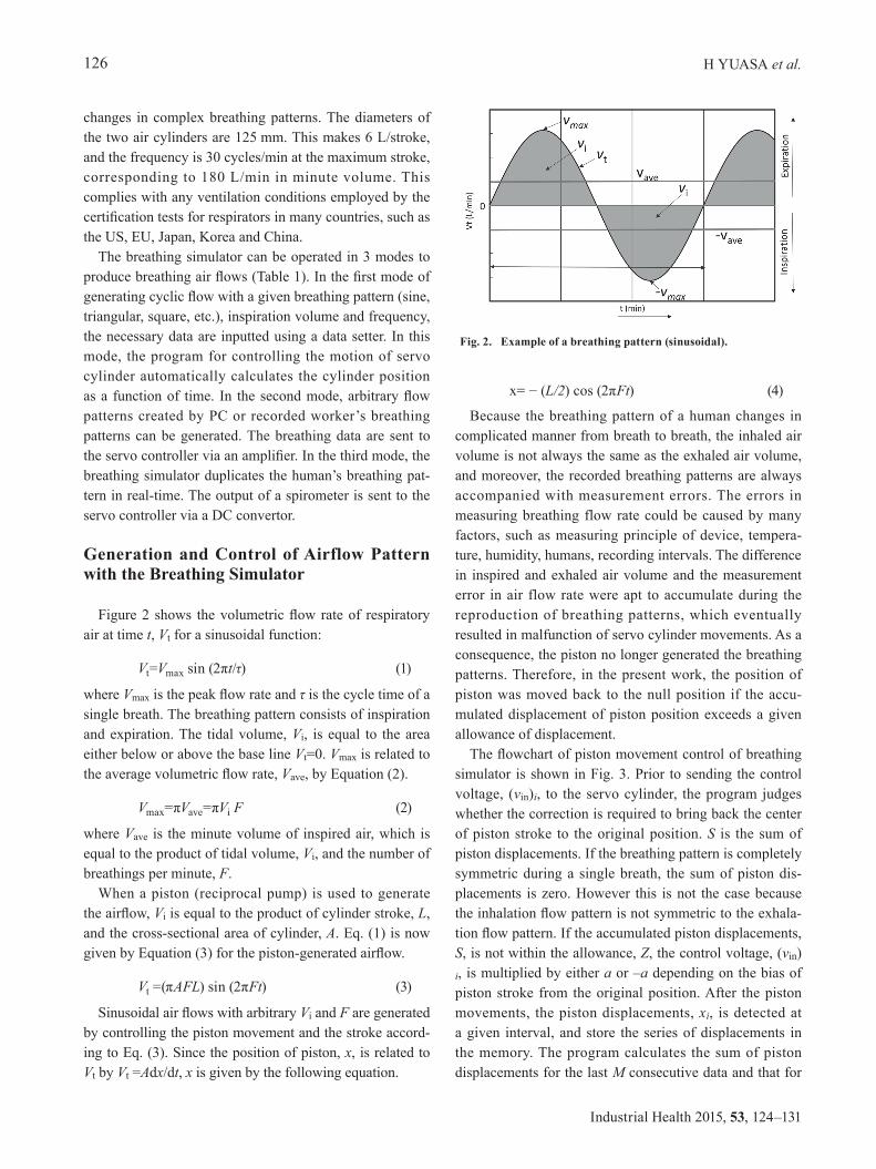
The test system is shown in Fig. 5. A sinusoidal air flow pattern of a given Vave was generated by the breathing simulator, and measured using a laminar flow meter (LFE-400LM, SOKKEN, Japan) and the breath recording device simultaneously. The recorded pressure data by the breath recording device were converted to the breathing airflow data and compared with the airflow pattern measured with the spirometer. Then the data obtained by the breath re-cording device were used to control the breathing simula-tor through a breathing data output unit for generating the sinusoidal airflow pattern. The test conditions are shown in Table 2. The air flow conditions tested were 10–40 L/min of minute volumes, which corresponds to the work rate from resting to very hard work. Test time was 60s and test was repeated from 3 to 5 times.
Recording and reproduction of welding workers’ breathing pattern
Breathing patterns of three workers who were engaged in welding of heavy machinery were recorded. The work-ers were all males (age: 31–33), who wore particulate respirator in their daily task. Prior to the test, the workers wore the breath recording device for checking the fitness of mask by “the negative pressure fit check method” to ensure the accuracy of measured breathing pattern. Next the worker carried out his task as usual. Sampling interval was 0.1 s, and the total recording points were 8,000. While
recording the breathing pattern, the action was videotaped to see the relationship between the breathing characteris-tics and actions. The recorded pressure change data were converted to breathing airflow patterns using PC, and they were used to reproduce the breathing pattern. The workers’ breathing patterns were reproduced in two ways where the position correction was on or off to show the effectiveness of the position correction.
Results and Discussions
Accuracy of breath recording device and breathing simulator
The measurement error of breath recording device and the accuracy of airflow reproduced by the breathing simu-lator when inputting a sinusoidal air flow pattern were investigated. Table 3 show the Vave measured by the breath recording device and those reproduced by the breathing simulator recorded by the breath recording device. The
Fig. 5. Setup for evaluating accuracy of the breath recording device and breathing simulator; Top: Genera-tion and recording of a known airflow pattern, Bottom: Reproduction of the recorded breathing pattern.
Table 2. Test conditions
Breathing condition 10 L/min (1.0 L/cycle, 10 cycles/min) 20 L/min (1.0 L/cycle, 20 cycles/min) 30 L/min (1.5 L/cycle, 20 cycles/min) 40 L/min (1.67 L/cycle, 24 cycles/min)
Test time 1 minSampling frequency 0.1 sRepetition 3–5 times at each breathing condition
BREATHING SIMULATOR FOR RESPIRATOR PERFORMANCE TEST 129
table shows that the recording error in Vave of the record-ing device is at most −4% for Vave =10–40 L/min of the generated air flow, and the error in Vave of the breathing simulator against the generated air volume is about −5%, suggesting that the system’s reliability is quite high. Three sinusoidal air flow patterns obtained by each condition matched each other. This confirms that the breathing pat-terns recorded and reproduced by the system are in good agreement with the input sinusoidal pattern. Because breathing volume of almost all Japanese workers are esti-mated less than 40 L/min, the system is applicable to most of Japanese workers26).
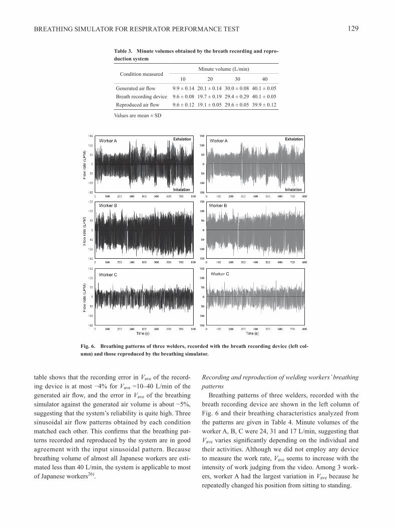
Recording and reproduction of welding workers’ breathing patterns
Breathing patterns of three welders, recorded with the breath recording device are shown in the left column of Fig. 6 and their breathing characteristics analyzed from the patterns are given in Table 4. Minute volumes of the worker A, B, C were 24, 31 and 17 L/min, suggesting that Vave varies significantly depending on the individual and their activities. Although we did not employ any device to measure the work rate, Vave seems to increase with the intensity of work judging from the video. Among 3 work-ers, worker A had the largest variation in Vave because he repeatedly changed his position from sitting to standing.
Table 3. Minute volumes obtained by the breath recording and repro-duction system
Condition measured Minute volume (L/min)
10 20 30 40
Generated air flow 9.9 ± 0.14 20.1 ± 0.14 30.0 ± 0.08 40.1 ± 0.05Breath recording device 9.6 ± 0.08 19.7 ± 0.19 29.4 ± 0.29 40.1 ± 0.05Reproduced air flow 9.6 ± 0.12 19.1 ± 0.05 29.6 ± 0.05 39.9 ± 0.12
Values are mean ± SD
Fig. 6. Breathing patterns of three welders, recorded with the breath recording device (left col-umn) and those reproduced by the breathing simulator.

H YUASA et al.130
Industrial Health 2015, 53, 124–131
The breathing patterns reproduced by the present breath-ing simulator are shown in the right column of Fig. 6. Figure 7 is an enlarged version of Fig. 6 where the breath-ing patterns of worker B reproduced with and without the null position correction are compared with the recorded breathing pattern. The characteristic parameters of breathing pattern (Vave and the peak inhalation airflow rate, PIF) are shown in Table 4. As seen in Fig. 7, in the case of no null position correction, there are some portions in inhalation pe-riod where the reproduced flow rate is lower than the origi-nal because the displacement of servo cylinder exceeded the maximum stroke. By using the null position correction, the stroke of serve cylinder never exceeded the maximum stroke so that the reproduced breathing patterns follow the original inhalation pattern pretty well. However, during the exhalation period, the reproduced flow rate with the null position correction was somewhat larger than the original. By applying the null position correction only to the inhala-tion period, we may reproduce the original breathing pattern more accurately. Table 4 shows the effectiveness of our correction program. The minute volume reproduced without the correction was decreased by 1.7–3.5 L/min, which was more than 10% decrease from the recorded Vave. However, with the correction, the error in Vave was improved to less than 5%. Moreover, Table 4 indicates that the correction program does not affect the peak inspiration air flow rate.
In the present work, the breath recording device and breathing simulator were applied to welding works, but this system should work for patients diagnosed with pul-monary diseases and administration of aerosol therapy.
Summary
We have developed a breathing simulator which can re-produce the actual breathing patterns of workers on heavy duty according to the recorded breathing patterns. The present breathing simulator is also capable of generating various waveforms synthesized by a PC. A new correction program for piston movement was introduced to reproduce the breathing patterns of actual workers for a long period of time by compensating the difference in inspiration and expiration air volume and the measurement errors in the recorded breathing flow rate. The combination of breath
Table 4. Characteristic parameters for welders’ breathing patterns
Worker WaveformAverage minute volume (L/min)
Peak inhalation air flow rate (L/min)
A
Recorded 24.3 127.9 Reproduced (Corrected)
23.0 128.2
Reproduced (Non-corrected)
21.6 127.1
B
Recorded 31.2 145.2 Reproduced (Corrected)
30.1 148.0
Reproduced (Non-corrected)
26.7 144.7
C
Recorded 16.6 85.0 Reproduced (Corrected)
15.9 91.0
Reproduced (Non-corrected)
14.9 89.0
Fig. 7. Comparison of reproduced breathing patterns with and with the null position correction with the one measured by the breath recording device.
Nomenclature
Symbol Meaning UnitA cross sectional area of piston cm2
a collection coefficient (-)F breathing frequency cycle/minL cylinder stroke cm
Mnumber of data for summation of positon displacements
(-)
S sum of piston displacements mmSA sum of piston displacements from 2M to M+1 mmSB sum of piston displacements from 0 to M mmt time min
Vave minute volume L/minvcont control voltage of servo cylinder VVi tidal volume L/cyclevin voltage input V
Vmax breathing peak air flow rate L/minVt breathing air flow rate L/minxi piston position mmZ allowance of piston displacements mm
BREATHING SIMULATOR FOR RESPIRATOR PERFORMANCE TEST 131
recording device and the breathing simulator were suc-cessfully applied to reproduce the breathing patterns of actual workers engaged in welding. The present system may be applied not only to test the effectiveness of respi-rators for workers on heavy duty, but to evaluate the dust collection performance and pressure drop of respirators, and calibrate various flow meters for measuring breathing patterns. In order to maximize the utilization of the pres-ent system, the accumulation of breathing patterns during various exercises would be recommended.
References
1) Silverman L, Lee G, Plotkin T, Sawyers LA, Yancey AR (1951) Air flow measurements on human subjects with and without respiratory resistance at several work rates. AMA Arch Ind Hyg Occup Med 3, 461–78.
2) Berndtsson G (2004) Peak inhalation air flow and minute volumes measured in a bicycle ergometer test. J Int Soc Resp Prot 21, 21–30.
3) Coyne K, Caretti D, Scott W, Johnson A, Koh F (2006) Inspiratory flow rates during hard work when breathing through different respirator inhalation and exhalation resistances. J Occup Environ Hyg 3, 490–500.
4) Lowry PL, Wheat LD, Bustos JM (1979) Quantitative fit-test method for powered air-purifying respirators. Am Ind Hyg Assoc J 40, 291–9.
5) Cohen HJ, Hecker LH, Mattheis DK, Johnson JS, Biermann AH, Foote KL (2001) Simulated workplace protection factor study of powered air-purifying and supplied air respirators. AIHAJ 62, 595–604.
6) Myers WR, Peach MJ 3rd, Cutright K, Iskander W (1984) Workplace protection factor measurements on powered air-purifying respirators at a secondary lead smelter: results and discussion. Am Ind Hyg Assoc J 45, 681–8.
7) Que Hee SS, Lawrence P (1983) Inhalation exposure of lead in brass foundry workers: the evaluation of the effectiveness of a powered air-purifying respirator and engineering controls. Am Ind Hyg Assoc J 44, 746–51.
8) Linders MJD, Mallens EPJ, Van Bokhoren JJGM, Kapteijin F, Moulijin JA (2003) Breakthrough of shallow activated carbon beds under constant and pulsating flow. Am Ind Hyg Assoc J 64, 173–80.
9) Nelson GO, Harder CA (1972) Respirator cartridge efficiency studies. IV. Effects of steady-state and pulsating flow. Am Ind Hyg Assoc J 33, 797–805.
10) R o w l a n d J J ( 1 9 7 0 ) S t u d y o f A e r o s o l F i l t r a t i o n Characteristics, M.S. Thesis. The University of Arkansas, Little Rock, Arkansas.
11) Brosseau LM, Ellenbecker MJ, Evans JS (1990) Collection of silica and asbestos aerosols by respirators at steady and
cyclic flow. Am Ind Hyg Assoc J 51, 420–6. 12) Haruta H, Honda T, Eninger RM, Reponen T, McKay
R, Grinshpun SA (2008) Experimental and theoretical investigation of the performance of N95 respirator filters against ultrafine aerosol particles tested at constant and cyclic flows. J Int Soc Resp Prot 25, 75–88.
13) Wang A, Richardson AW, Hofacre KC (2012) The effect of flow pattern on collection efficiency of respirator filters. J Int Soc Resp Prot 29, 41–54.
14) Nelson GO, Johnsen RE, Lindeken CL, Taylor RD (1972) Respirator cartridge efficiency studies. 3. A mechanical breathing machine to simulate human respiration. Am Ind Hyg Assoc J 33, 45–50.
15) Myojo T (1989) Breathing pattern simulation using slit/cam valve. Am Ind Hyg Assoc J 50, 240–4.
16) Deno NS (1984) Automatic breathing and metabolic simulator: the respiring robot. J Int Soc Resp Prot 2, 38–52.
17) Reimers SD (1984) The development of a new automated breathing metabolic simulator. J Int Soc Resp Prot 2, 170–96.
18) Kyriazi N (1986) Development of an Automated Breathing and Metabolic Simulator, an Information Circular U.S. Bureau of Mines, to the U.S. Department of the Interior, Report Number 9110.
19) Kyriazi N (2011) Performance comparison of breathing and metabolic simulators. J Int Soc Resp Prot 28, 1–25.
20) Berndtsson G, Ekman L (2003) A new simplified technique for measuring inspiratory flow characteristics. J Int Soc Resp Prot 20, 91–101.
21) Groves WA (2006) Personal sampling system for measuring workplace protection factors for gases and vapors. J Int Soc Resp Prot 26, 30–43.
22) Tanaka S, Tanaka M, Kimura K, Nozaki K, Seki Y (1996) Breakthrough time of a respirator cartridge for carbon tetrachloride vapor flow of workers’ respiratory patterns. Ind Health 34, 227–36.
23) Yuasa H, Fukiura K, Kimura K, Emi H, Nozaki K (2008) A study on respiration sampling device for worker. J ISRP Jap Sec Resp Prot 20, 2–8.
24) Yuasa H, Shimizu E, Kimura K, Emi H, Nozaki K (2008) Performance of breathing-synchronized powered air-purifying respirator under simulated usage conditions. J Int Soc Resp Prot 25, 107–18.
25) Grinshpun SA, Haruta H, Eninger RM, Reponen T, McKay RT, Lee SA (2009) Performance of an N95 filtering facepiece particulate respirator and a surgical mask during human breathing: two pathways for particle penetration. J Occup Environ Hyg 6, 593–603.
26) Haruta H, Yuasa H, Shimizu E, Tachi K, Kimura K, Emi H, Nozaki K (2011) Sampling and estimation of workers’ work rate using their breathing patterns. J ISRP Jap Sec Resp Prot 23, 2–12.