brazing & soldering today€¦ · brazing & soldering today welding journal 45 called outer...
TRANSCRIPT

BRAZING & SOLDERING TODAY
FEBRUARY 201444
Labyrinth Seals
To reduce leakage flows in turbo ma-chines, tight operational clearances be-tween stator and rotor parts are desir-able. With reduced clearances, the risk ofrub contact increases. In such situations,the stator is fitted with an abradablestructure or coating that minimizes dam-age to the rotor when such rub contactoccurs.
A popular abradable structure ismetallic honeycomb, which derives itsabradability from a low structural den-sity, typically in the range of 8 to 20% ofthe bulk alloy density. Honeycomb seallands are always used as part of a
labyrinth seal, as schematically shown inFig. 1. Seal fins on the rotor together withthe stator wall form cavities. A gas flow isaccelerated as it enters into the labyrinthfrom the high-pressure side through anannular gap (A). Subsequently, the flowarea cross section increases dramaticallyas the flow enters the cavity (B) causingit to dissipate flow energy through a re-duction of speed and pressure in a turbu-lent flow. A series of such events, creat-ing a tortuous path for the gas flow,allows it to maintain a sizable pressuredifference across the labyrinth seal, al-though a certain amount of leakage flowis inevitable.
The amount of leakage flow, however,
depends on the size of the clearance C.Small operational clearances can only bedesigned if the stator wall is lined with astructure that can easily be cut by the ro-tating seal teeth without damaging oroverheating them — Fig. 2.
Engine Seal Locations
In a gas turbine engine, there is a largenumber of locations that require sealingagainst leakage flows. Honeycombs areused in both compressor sealing as well asturbine sealing applications.
However, air seals in low-pressure tur-bine (LPT) modules remain a domain ofhoneycomb as abradable seals. Typicalfive-stage, low-pressure aero engine tur-bine modules have ten gas path seal loca-tions over shrouded blades and vanes, so
Selecting Materials for Brazing aHoneycomb in Turbine Engines
DIETER SPORER([email protected]) is with
Sulzer Metco Management AG,Winterthur, Switzerland. DIENTJE
FORTUNA ([email protected]) iswith Sulzer Metco (U.S.), Inc., Troy, Mich.
Based on a paper presented at IBSC 2012,5th International Brazing and SolderingConference, April 22–25, Las Vegas, Nev.
Increasing aircraft turbine engineefficiency involves higher operatingtemperatures that introduce a number of engine manufacturing concerns
BY DIETER SPORER AND DIENTJE FORTUNA
Fig. 1 — Laybrinth seal schematic.
Fig. 2 — Stepped layyrinth seal withhoneycomb seal lands.
Fortuna Layout B&S_Layout 1 1/15/14 8:18 AM Page 44

BRAZING & SOLDERING TODAY
45WELDING JOURNAL
called outer and inner air seals, and threeinter-stage seals, all using honeycomblands to minimize clearances and leakageflows thereby improving module andoverall engine efficiency.
Figure 3 shows the honeycomb linedinterstage seals and knife edges coatedwith an abrasive, thermally sprayed alu-mina/titania, to further reduce the wearof the rotor parts during rub incursions.
To improve overall engine thermal ef-ficiencies, there is an ongoing effort topush turbine entry temperatures tohigher values. First and foremost, this af-
fects the high-pressure turbine (HPT)hardware, but with increased tempera-tures there, the LPT stages and their airseals see steadily increasing tempera-tures as well. Typically, the first LPTstages of modern engine designs todaysee temperatures of up to 1100°C (2010°F) on take-off conditions. Later stageswill see lower temperature loading, typi-cally down to 600°C (1110°F). The sealsmust withstand these temperatures forextended periods of time and underhighly cyclic loading conditions. There-fore, apart from good abradability of thehoneycomb seal lands, they must showadequate oxidation and hot gas corrosionresistance to survive the aggressive serv-ice environment.
Honeycomb and SealComponent Manufacture
Seal honeycomb is manufacturedfrom thin metallic foil, typically 75 to 150μm (0.003 to 0.006 in.) thick, which is cor-rugated and then laser spot welded in thenodes, to hold adjacent corrugated stripwalls together, forming hexagonal cells.The welded honeycomb structure can becut and shaped to fit backing membersonto which the honeycomb is first tackwelded and then joined by means of braz-ing. Welded honeycomb can also beformed into rings that are then brazed toturbine components to form integral ringseal faces such as interstage seals. To pro-vide inner air seals, honeycomb segmentsare brazed to the shrouds of the nozzleguide vanes while outer air seals are oftenprovided by brazing honeycomb lands tosheet metal segments that are then in-serted into holder structures of the LPTcasing. Such a brazed outer seal segmentis shown in Fig. 4.
Honeycomb Materials
Seal honeycomb for application in en-gine compressors is frequently madefrom stainless steel foil. However, for thetemperatures encountered in the turbinesection, more heat- and oxidation-resist-ant materials have to be used. The mate-rials are typically nickel-based alloys withhigh chromium alloying content.
For enhanced oxidation resistance,Haynes® 214, which is a material oftenused, shows a high alloying content ofaluminum. The most popular alloys forturbine seal honeycomb applications areHastelloy® X and Haynes® 214. Ni-monic 86™ is used in some specialty ap-plications. Two iron-based materials,having a high concentration of aluminumand additions of rare earth metal (Y, Hf,and Zr) or oxide (Y2O3), are generallyreferred to as FeCrAlYs. Of these iron-based materials, MI2100 composition isalready in commercial use in gas turbineengine sealing applications, the yttria dis-persion-strengthened FeCrAlY material,MI 2200, remains an experimental alloy.
Braze Filler Materials
To accommodate the high service tem-peratures, turbine side-seal honeycombis typically brazed with nickel- or cobalt-based braze filler material (BFM) pro-viding high initial as well as high remelttemperatures. Table 1 gives an overviewof common braze filler compositions.
Requirements for BrazingSeal Honeycomb
The brazing of the honeycomb to acarrier structure does not only need tojoin these two elements together but alsoneeds to reinforce the honeycomb struc-ture itself. This is achieved by filling thegaps between adjacent honeycomb wallswith braze filler material using capillaryaction and forming fillets at the base ofthe honeycomb. However, it is not desir-able that the BFM travels up the entirehoneycomb height. Typical specificationswill limit the height of the fillet or howhigh the braze can climb up the faces ofeach cell. Filling of the nodes is typicallyalso required to reach a certain minimumpercentage of the honeycomb height, for
Fig. 4 — Stepped outer air seal segmentwith brazed on seal honeycomb of 1.59-mm (1⁄16-in.) cell size.
Fig. 3 — Honeycomb-lined interstageseals and abrasive-coated seal teeth.
Table 1 — Chemical Composition and Liquidus Temperature of Braze Filler Metals
Braze Ni Cr Si B Others Liquidus
AMS 4777 Bal. 7 4.5 3.0 3 Fe 1000°C1830°F
AMS 4778 Bal. 4.5 3.2 1040°C1900°F
AMS 4779 Bal. 3.5 2.0 1065°C1950°F
Fortuna Layout B&S_Layout 1 1/15/14 8:19 AM Page 45

BRAZING & SOLDERING TODAY
FEBRUARY 201446
example, 80% minimum or d/e > 0.8 (Fig.5) to ensure proper seal integrity andavoid honeycomb degradation throughaerodynamically induced fatigue.
While in a liquid state, the BFM willnot only wet the nodal walls and base butalso penetrate the backing member andcreate a braze diffused zone that maycontain undesirable phases such aschrome borides (CrxBy) or silicides. Sim-ilarly, the liquid BFM may also alter thechemistry of the thin honeycomb cellwalls by in-diffusion of elements from thebraze filler into the honeycomb materialor diluting the concentration of certainhoneycomb material alloying elements byout-diffusion into the braze composition.By comparing the chemistries of thebraze fillers and the honeycomb materi-als, it becomes evident that there is a highpotential for diffusion processes based onthe significant differences in chemicalcomposition and large concentration gra-dients resulting from these.
Oxidation of Plain andBrazed Honeycomb
Oxidation Resistance of Plain Foil
To provide seals that can withstandhigher temperatures, first and foremost,the honeycomb material itself needs to beresistant to high-temperature oxidationand corrosion. To determine a basemetal’s capability, a simple air oxidationtest at 1100°C was carried out. The oxi-dation resistance was measured using thesample weight change per unit surfacearea after 24 h of exposure as a yardstick.Two performance classes were clearly re-vealed through the testing. The differ-ence between the classes lies in the self-protection mechanism of the differentmaterials. Nimonic 86™, Inconel® 617,and Hastelloy® X primarily form chro-mia (Cr2O3) surface oxide layers. How-ever, these layers are not stable andtherefore not protective at the selectedtest temperature. The MI 2100/2200 andHaynes® 214, all containing a high per-centage of aluminum, tend to form Al2O3surface oxide layers that are stable andprotective even at 1100°C.
Weight change in the processed sam-ples is a measure of the oxidation process
occurring to the engine components.Overall, the weight change is very smallfor the alumina formers compared to theresults for the chromia formers in air ox-idation at 1100°C.
The oxide layers on the FeCrAlY foilsamples are thin and well adhered. Thematerials MI 2100 and MI 2200 tend toform fine-grained α-Al2O3 layers andonly partly Cr-rich oxide phases, whileHaynes® 214 shows a higher degree ofless desirable NiCr2O4 spinel oxides andcoarse chromia embedded in the alumina(Refs. 1, 2). Apart from that, no signifi-cant internal oxidation of the foil materi-als was observed for the tests that wereperformed.
Thickness Effects
As the oxidation resistance of the hon-eycomb foil materials with high alu-minum content relies on the formation ofAl2O3, with Cr2O3 being a lot less resist-ant at high temperature, the amount ofavailable matrix aluminum plays an emi-nent role. The formation of protectivealumina requires aluminum from the ma-trix and as the protective oxide grows inthickness or needs to be replaced afterhaving spalled off, matrix aluminum willbe consumed. Once the aluminum con-centration in the matrix falls below a cer-tain critical level, formation of Al2O3 atthe surface is no longer guaranteed and
Fig. 5 — Designations of geometrical characteristics of brazed honeycomb. Sectionthrough nodal walls (schematic).
Fig. 6 — Condition of nickel-based seal honeycomb as returned from engine service.Cell size is 1.59 mm (1⁄16 in.).
Fortuna Layout B&S_Layout 1 1/15/14 8:19 AM Page 46
BRAZING & SOLDERING TODAY
47WELDING JOURNAL
the oxidation mode changes drasticallytoward significantly higher oxidationrates, which, at high temperatures, canlead to accelerated or catastrophic oxida-tion failure, called break-away oxidation.
One solution for this type of failure isto increase the thickness of the honey-comb foil. The additional thickness willhold up to the depletion of aluminum fora longer period of time increasing thetime to failure. Designers need to takethese effects into consideration when de-signing honeycomb seals for use at ex-treme temperatures, even if the thickerfoil material will increase the structuraldensity of the honeycomb and compro-mise its abradability.
Oxidation of Brazed Honeycomb
Figure 6 shows an enlarged top viewonto a honeycomb seal face as it is re-turned from engine service. A preferredoxidation attack is observed at the nodalwalls as indicated with arrows. In the as-brazed condition, this would have been afree surface entirely composed of brazefiller material, created by the BFM climb-ing up the nodal joints during the brazingoperation. The oxidation of the BFMpenetrates the nodal joint to a certain de-gree, thereby reducing the wall thicknessof the neighboring single foil wall. Withthe reduced thickness, the cell wall haslittle chance of surviving further oxida-tion and/or mechanical loading and willultimately fail by cracking, as is seen inthe lower right-hand corner of Fig. 6.
It is difficult to say whether the ulti-mate failure of the honeycomb is causedby mechanical/aerodynamic loading ofthe weakened structure or further oxida-tion. However, what becomes apparent
from Fig. 6 is the fact that the failuremechanism is induced by preferred oxi-dation of excess braze filler metal.
Compared to the single foil walls ofthe honeycomb structure in Fig. 6, thedouble walls look relatively healthy withless internal oxidation compared to thethinner sections. This may be due to thethickness effect discussed above. In anycase, it leads to the nodal walls survivingthe service exposure much better thanthe single walls, which can ultimately leadto the nodal walls being the only part ofthe seal structure to remain intact, an ef-fect that is called “tombstoning.”
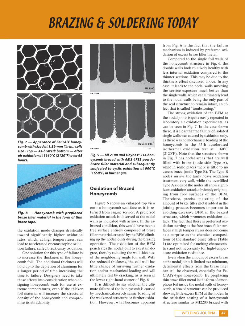
The strong oxidation of the BFM atthe nodal joints is quite easily repeated inlaboratory air oxidation experiments, ascan be seen in Fig. 7. In the case shownthere, it is clear that the failure of isolatedsingle walls was caused by oxidation only,as there was no mechanical loading of thehoneycomb in the 65-h acceleratedisothermal oxidation test at 1160°C(2120°F). Note that the structure shownin Fig. 7 has nodal areas that are wellfilled with braze (node side Type A),while in some places there is little to noexcess braze (node Type B). The Type Bnodes survive the fairly heavy oxidationtreatment very well, while the overfilledType A sides of the nodes all show signif-icant oxidation attack, obviously originat-ing from free surfaces of the BFM.Therefore, precise metering of theamount of braze filler metal added in thejoining process becomes important inavoiding excessive BFM in the brazedstructure, which promotes oxidation at-tack. The fact that there is preferred oxi-dation starting at the free braze filler sur-faces at high temperatures does not comeas a surprise as the chemical composi-tions of the standard braze fillers (Table1) are optimized for melting characteris-tics and not necessarily for high-temper-ature oxidation resistance.
Even when the amount of excess brazeat the nodal joints is limited to a minimum,detrimental effects from the braze fillercan still be observed, especially for Fe-CrAlY-type honeycomb. By preplacingthin braze filler metal in the form of amor-phous foil inside the nodal walls of honey-comb, a brazed structure can be producedshowing little excess BFM at the nodes. Inthe oxidation testing of a honeycombstructure similar to MI2200 brazed with
Fig. 7 — Apperance of FeCrAlY honey-comb with sized at 1.59-mm (1⁄16-in.) cellssize . Top — As-brazed; bottom — afterair oxidation at 1160°C (2120°F) over 65hours.
Fig. 9 — MI 2100 and Haynes® 214 hon-eycomb brazed with AMS 4783 powderbraze filler material and subsequentlysubjected to cyclic oxidation at 900°C(1650°F) in burner gas.
Fig. 8 — Honeycomb with preplacedbraze filler material in the form of thinbraze tape.
Fortuna Layout B&S_Layout 1 1/15/14 8:20 AM Page 47

BRAZING & SOLDERING TODAY
FEBRUARY 201448
BNi-5a amorphous foil, it becomes appar-ent that the oxidation resistance of thenodes suffers from the preplaced brazefoil. The impression is that the BFM poi-soned the composition by in-diffusion ofundesirable elements or by diluting thealuminum concentration locally.
With the need for more precise me-tering of the BFM, methods other thanfilling the honeycomb with braze powderneed to be applied. One such method isthe use of braze tape. Braze tape con-taining the common BFMs is available ina variety of thicknesses and thereforebraze filler amounts can be controlledper unit surface area and is preplaced inthe honeycomb structure, as shown inFig. 8. Another method of predetermin-ing the amount of braze filler more pre-cisely is the use of all-metallic braze foil,which can also be preplaced in the hon-eycomb structure (Brazcor™ honey-comb) as discussed above. However,using metallic braze foil significantlyadds to cost and the complexity of manu-facture so that the use of braze tape be-comes the preferred method and increas-ingly popular.
Fatigue Cracking
Another degradation mechanism ob-served for brazed honeycomb is fatiguecracking in situations where mechanicalloading and oxidation are superimposedsuch as in cyclic oxidation or burner rigtesting. Figure 9 shows Haynes® 214 andMI 2100 honeycomb after cyclic oxida-tion at 900°C (1650°F) over 200 h. Bothhoneycombs were brazed with AMS 4783BFM, which was selected for its highmelting temperature to produce a high-temperature seal. While the combinationMI 2100/AMS 4783 seemed to survive thecyclic oxidation well, the combinationHaynes® 214/AMS 4783 showed signifi-cant deterioration in the structure andformation of cracks in the honeycombwall metal. At higher magnification of theHaynes® 214 honeycomb, several fea-tures became apparent — Fig. 10. First ofall, a thick surface oxide layer could beobserved in parallel with a fair amount ofinternal oxidation along cracks that hadformed and obviously propagated alonggrain boundaries of the coarsened struc-ture of the honeycomb material.
Secondly, a high number of spherical
and needle-shaped precipitates wereseen. It is worth noting that similar fea-tures were not observed for the unbrazedmaterial in air or burner gas oxidation,which leads to the assumption that theiroccurrence is linked to the brazing of thestructure.
Clearly, the above example showscombining a material that reflects goodhigh-temperature oxidation resistance(Haynes® 214) with a braze material ofsufficiently high melting temperature(AMS 4783) does not automatically pro-duce a well-performing high-tempera-ture seal. The pairing MI 2100 and AMS4783 resulted in a much more stable sealconfiguration that shows good perform-ance at up to 1100°C and only starts to de-teriorate at 1200°C (2190 °F) by a mech-anism initiated by diffusion of siliconfrom the braze filler into the honeycombmaterial (Ref. 3).
Summary
The performance of honeycombstructures made from alumina-forming,high-temperature-resistant NiCrAl, andFeCrAlY materials is significantly im-pacted by the presence of less oxidation-resistant braze filler materials necessaryto join the abradable honeycomb to asupporting structure. Several failuremechanisms are observed that can besummarized as BFM-induced oxidationand/or braze filler oxidation-induced fa-tigue of seal honeycomb. Therefore, theneed exists to develop braze filler materi-als with much improved oxidation resist-ance to provide honeycomb seal lands foruse in turbine labyrinth seals at operatingpeak temperatures above 1100°C.
Conclusions
To improve the thermal efficiency ofjet engines, there is a trend toward higherturbine entry temperatures while reduc-ing the cooling effort. This leads to ever-increasing temperatures that honeycombseals in the low-pressure turbine moduleof modern engines will have to withstand.While metallic foil alloy materials thatcan withstand a turbine hot gas environ-ment at temperatures in excess of 1100°Care available, suitable braze filler materi-als to join seal-type honeycomb fabri-cated from these high-temperature-re-
sisting materials are not. Various degra-dation mechanisms of brazed seals athigh temperature, all directly or indi-rectly linked to the presence of brazefillers with fairly limited high-tempera-ture oxidation and hot gas corrosion re-sistance, can be detected. These can besummarized as braze filler metal-inducedoxidation failure or braze filler oxidation-induced fatigue failure. Clearly, there is aneed for more oxidation-resistant brazesfor joining ultrahigh-temperature sealhoneycomb.
When designing honeycomb seals foruse at extreme temperatures, the influ-ences of honeycomb wall thickness on theseal lifetime as well as compatibility ofbraze filler and honeycomb materialneed to be taken into consideration. Min-imizing the amount of excess braze fillercovering the seal structure must also beachieved to provide sufficient durabilityof the seals in high-temperature service.♦
References
1. Smarsly, W., et al. 2005. Advancedhigh temperature turbine seals materialsand designs. Materials Science Forum,Vols. 492, 493, pp. 21–26.
2. Sporer, D. R., and Shiembob, L. T.2004. Alloy selection for honeycomb gaspath seal systems. ASME Turbo Expo,Vienna, Austria, June. Paper numberGT2004-53115.
3. Potter, D. J., Chai, Y. W., and Tat-lock, G. J. 2009. Improvements in honey-comb abradable seals. Materials at HighTemperatures 26: 27–35.
Fig. 10 — Haynes® 214 honeycomb athigher magnification showing cracksand significant deterioration in thestructure.
Fortuna Layout B&S_Layout 1 1/15/14 8:20 AM Page 48