braun corporation fmvss no. 403 quick reference ... corporation fmvss no. 403 quick reference...
TRANSCRIPT
Braun Corporation FMVSS No. 403 Quick Reference Installation Sheet 30954 Rev: B
Clear Door Opening Width
Maximum Floor-to-Ground
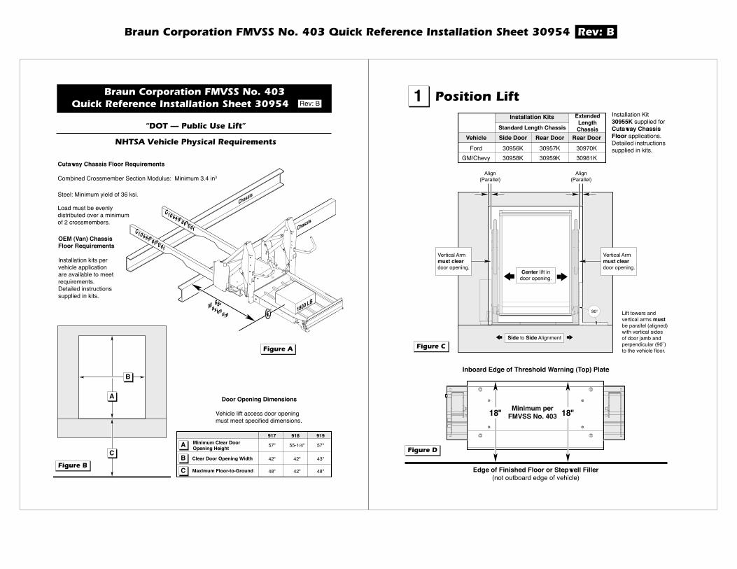
OEM (Van) ChassisFloor Requirements
Installation kits pervehicle applicationare available to meetrequirements.Detailed instructionssupplied in kits.
Load must be evenlydistributed over a minimumof 2 crossmembers.
Cutaway Chassis Floor Requirements
Combined Crossmember Section Modulus: Minimum 3.4 in3
Steel: Minimum yield of 36 ksi.
�����������������������
�����������������������������������
sissahC
sissahC
mssorC
rebme
mssorC
mereb
"86mixaM
mu
BL 0081CL
B
A
C
��������
��������
Door Opening Dimensions
Vehicle lift access door openingmust meet specified dimensions.
917 918 919
57" 55-1/4" 57"
42" 42" 43"
48" 42" 48"
Minimum Clear DoorOpening HeightA
B
C
����������������������������������������������������������������������� Rev: B 1 �������������
90�
Vertical Armmust cleardoor opening.
Vertical Armmust cleardoor opening.
Center lift indoor opening.
Side to Side Alignment
Align(Parallel)
Align(Parallel)
Lift towers andvertical arms mustbe parallel (aligned)with vertical sidesof door jamb andperpendicular (90˚)to the vehicle floor.
��������
Vehicle Side Door Rear Door Rear DoorFord 30956K 30957K 30970K
GM/Chevy 30958K 30959K 30981K
ExtendedLengthChassisStandard Length Chassis
Installation Kits Installation Kit30955K supplied forCutaway ChassisFloor applications.Detailed instructionssupplied in kits.
��������
Edge of Finished Floor or Stepwell Filler(not outboard edge of vehicle)
Inboard Edge of Threshold Warning (Top) Plate
18"18" Minimum perFMVSS No. 403
Braun Corporation FMVSS No. 403 Quick Reference Installation Sheet 30954 Rev: B
sissahC
��������
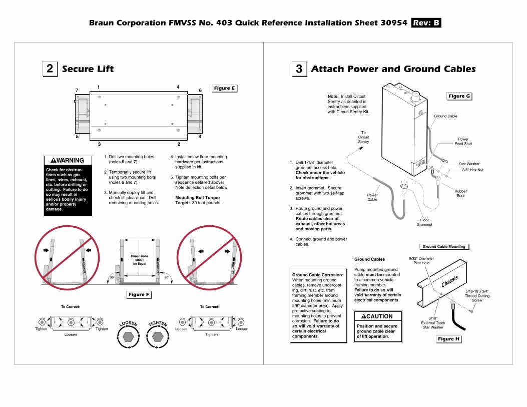
RubberBootPower
Cable
FloorGrommet
ToCircuitSentry
Ground Cable
Note: Install CircuitSentry as detailed ininstructions suppliedwith Circuit Sentry Kit.
1. Drill 1-1/8" diametergrommet access hole.Check under the vehiclefor obstructions.
2. Insert grommet. Securegrommet with two self-tapscrews.
3. Route ground and powercables through grommet.Route cables clear ofexhaust, other hot areasand moving parts.
4. Connect ground and powercables.
Ground Cables
Pump mounted groundcable must be mountedto a common vehicleframing member.Failure to do so willvoid warranty of certainelectrical components.
Ground Cable Corrosion:When mounting groundcables, remove undercoat-ing, dirt, rust, etc. fromframing member aroundmounting holes (minimum5/8" diameter area). Applyprotective coating tomounting holes to preventcorrosion. Failure to doso will void warranty ofcertain electricalcomponents.
Position and secureground cable clearof lift operation.
CAUTION
��������
5/16"External ToothStar Washer
5/16-18 x 3/4"Thread Cutting
Screw
9/32" DiameterPilot Hole
Ground Cable Mounting
3 ������������������������������
7 61 4
5 83 2
��������
��������
WARNINGCheck for obstruc-tions such as gaslines, wires, exhaust,etc. before drilling orcutting. Failure to doso may result inserious bodily injuryand/or propertydamage.
1. Drill two mounting holes(holes 6 and 7).
2. Temporarily secure liftusing two mounting bolts(holes 6 and 7).
3. Manually deploy lift andcheck lift clearance. Drillremaining mounting holes.
4. Install below floor mountinghardware per instructionssupplied in kit.
5. Tighten mounting bolts persequence detailed above.Note deflection detail below.
Mounting Bolt TorqueTarget: 30 foot pounds.
2 �����������
To Correct:
DimensionsMUST
be Equal
90�90�
To Correct:
�
29823 �
29823
�
29823
LOOSEN LOOSEN LOOSENTIGHTEN TIGHTEN TIGHTEN
TIGHTEN
LoosenTighten Tighten
TightenLoosen Loosen
LOOSEN
Star Washer3/8" Hex Nut
PowerFeed Stud

Braun Corporation FMVSS No. 403 Quick Reference Installation Sheet 30954 Rev: B
��������
WARNINGInstall and verifyproper operation ofall NHTSA mandatedinterlocks asspecified. Failure todo so will result in anon-compliantinstallation and mayresult in seriousbodily injury and/orproperty damage.
Vehicle and Lift Interlocks
The pump module is equippedwith a lift interface 9-circuitconnector (female socket). Amating 9-circuit connector (maleplug) is supplied.
To meet minimum NHTSArequirements, connect to vehicleinterlock harness as follows:
• Pin 6 - Vehicle Secure(Grey/Red)
• Pin 7 - Lift Stowed(Yellow/Light Blue)
Optional Interlock Kits
Universal Interlock Kit 30940K isavailable for easy interface withvehicle OEM electronic signals.
Instrument Panel Display Kit30938K provides an LED PanelDisplay that interfaces withBraun Universal Interlock Kit30940K.
Note: Detailed installationinstructions are supplied withinterlock kits.
4 ������������������
Manufacturerʼs Part NumbersConnector: AMP 172169Terminal:TYCO 770904-3
INTERLOCKCONNECTOR - J2
654321
SIGNAL DEFINITIONNO.9-COND WIRE CODE
789
VEHICLE SECURE (INPUT)NOT USED
SYNC*CLOCK*
SERIAL DATA*RESERVED
LIFT STOWED (OUTPUT)GROUND
LIGHT CONTROL (OUTPUT)
46 513 2
79 8
* OPTIONAL DIAGNOSTIICS PER INTERLOCK KIT INSTRUCTIONS
13 2
46 5
79 8
VEHICLE SECURE SIGNAL
(Grey/Red)kcolretnI oTDisconnect
andKEEP
2
1
3
Disconnect
tfiL
pmuP
eludoM
Connect
As
Sdeppih
LIFT STOWED SIGNAL (Yellow/Light Blue)
PUMP MODULECONNECTOR - J12
654321
SIGNAL DEFINITIONNO.9-COND WIRE CODE
7
VEHICLE SECURE (INPUT)NOT USED
SYNCCLOCK
SERIAL DATA RESERVED
LIFT STOWED (OUTPUT) 64 531 2
97 8
31 2
64 5
97 8
8 GROUNDLIGHT CONTROL (OUTPUT)9
6 ���������������������
Inboard Outboard
Wedges
Angle Aequals
Angle B.
•
B
��������
Adjustments to platformangle may be required ifbase plate wedges areused.
Floor Level Positioning:
Reset floor level positioningif wedges are used. SeeMicroswitch AdjustmentInstructions at right.
5
LOOSEN
TIGHTEN
Turncounterclockwise
tolower
outboard endof platform
Turnclockwise
toraise
outboard endof platform
��������
A
Approximately1" Clearance
Reset floor levelposition as specifiedin MicroswitchAdjustment Instruc-tions if wedges areused. Failure to do somay result in seriousbodily injury and/orproperty damage.
WARNING
Braun Corporation FMVSS No. 403 Quick Reference Installation Sheet 30954 Rev: B
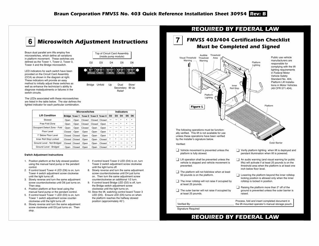
Visual ThresholdWarning
AudibleThresholdWarning
InnerRoll Stop
PlatformLighting
PlatformLighting
Platform
Outer Barrier
��������
Verify platform lighting when lift is deployed andpendant illumination when lift is powered.
An audio warning (and visual warning for publiclifts) will activate if at least 25 pounds is on thethreshold area when the platform is at least oneinch below floor level.
Lowering the platform beyond the inner rollstoplocking position is allowed only when the innerrollstop is locked in position.
Raising the platform more than 3” off of theground is prevented unless the outer barrier israised.
Verified:
Vehicle movement is prevented unless theplatform is fully stowed.
Lift operation shall be prevented unless thevehicle is stopped and vehicle movement isprevented.
The platform will not fold/stow when at least50 pounds is on the platform.
The inner rollstop will not raise if occupied byat least 25 pounds.
The outer barrier will not raise if occupied byat least 25 pounds.
Verified By:Process, fold and insert completed document inthe lift-mounted operatorʼs manual storage pouch.
7 �����������������������������������������������������������������
Signature Required
�����������������������
�����������������������
The following operations must be function-ally verified. This lift is not available for useunless these operations have been verifiedby the installerʼs signature below.
DOWN
DLOF
UP
DLOFNU
ThresholdArea
7. If control board Tower 2 LED (D4) is on, turnTower 2 switch adjustment screw clockwiseuntil the light turns off.
8. Slowly reverse and turn the same adjustmentscrew counterclockwise until D4 just turnson. Then turn the same adjustment screwcounterclockwise an additional 1/2 turn.
9. If control board Bridge LED (D2) is off, turnthe Bridge switch adjustment screwclockwise until the light turns on.
10. Stow the lift, watching control board Tower 3LED (D5). Ensure LED (D5) turns on whenthe platform reaches the halfway stowedposition (approximately 45�).
6 �����������������������������������6Braun dual parallel arm lifts employ fivemicroswitches, which define all variationsin platform movement. These switches aredefined as the Tower 1, Tower 2, Tower 3,Tower 4 and the Bridge microswitch.
LED indicators for each switch have beenprovided on the Circuit Card Assembly(CCA) as shown in the diagram at right.These indicators will provide an easymethod to initially adjust these switches aswell as enhance the technicianʼs ability todiagnose maladjustments or failures in theswitch circuits.
The LEDs associated with these microswitchesare listed in the table below. The star defines thelighted indicator for each particular combination.
TOWER3R58 D5
TOWER2R54 D4
TOWER1R48 D3
BRIDGED2
TOWER4R63 D6
D2 D3 D4 D5 D6
Bridge Unfold Up DualSecondary
Relief
Stow/IB Up
Top of Circuit Card Assembly(inside pump module) Public use vehicle
manufacturers areresponsible forcomplying with the liftlighting requirementsin Federal MotorVehicle SafetyStandard No. 404,Platform Lift Installa-tions in Motor Vehicles(49 CFR 571.404).
Switch Adjustment Instructions
1. Position platform at the fully stowed positionusing the manual hand pump or the pendantcontrol.
2. If control board Tower 4 LED (D6) is on, turnTower 4 switch adjustment screw clockwiseuntil the light turns off.
3. Slowly reverse and turn the same adjustmentscrew counterclockwise until D6 just turns on.Then stop.
4. Position platform at floor level using themanual hand pump or the pendant control.
5. If control board Tower 1 LED (D3) is on, turnTower 1 switch adjustment screw counter-clockwise until the light turns off.
6. Slowly reverse and turn the same adjustmentscrew clockwise until D3 just turns on. Thenstop.
StowedFree Fold Zone
Occupant Detect Zone - FoldFloor Level
1" Below Floor LevelInner Roll Stop Locked
Ground Level - Not BridgedGround Level - Bridged
Lift ConditionOpen Open Closed Closed ClosedOpen Open Closed Closed OpenOpen Open Closed Open Open
Closed Open Open Open OpenClosed Closed Open Open OpenClosed Closed Open Open ClosedClosed Closed Open Open ClosedOpen Closed Open Open Closed
— — • • •
— — • • —— — • — —• — — — —• • — — —• • — — •
• • — — •
— • — — •
Bridge Tower 1 Tower 2 Tower 3 Tower 4 D2 D3 D4 D5 D6IndicatorsMicroswitches
Braun Corporation FMVSS No. 403 Quick Reference Installation Sheet 30954 Rev: B
���������������������������
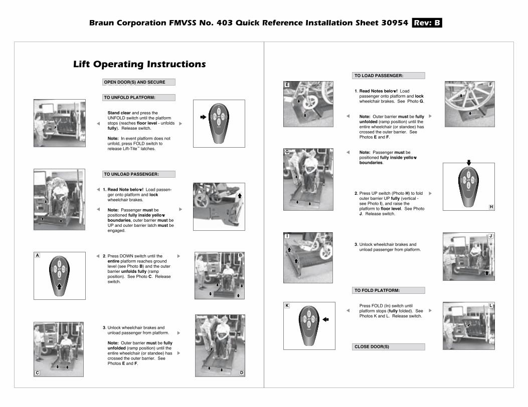
To Unfold Platform (Out):
UP
DOWN
DLOFNU
DLOF
AUP
DOWN
DLOFNU
DLOF
C
B
D
OPEN DOOR(S) AND SECURE
TO UNFOLD PLATFORM:
Stand clear and press theUNFOLD switch until the platformstops (reaches floor level - unfoldsfully). Release switch.
Note: In event platform does notunfold, press FOLD switch torelease Lift-Tite™ latches.
TO UNLOAD PASSENGER:
1. Read Note below! Load passen-ger onto platform and lockwheelchair brakes.
Note: Passenger must bepositioned fully inside yellowboundaries, outer barrier must beUP and outer barrier latch must beengaged.
2. Press DOWN switch until theentire platform reaches groundlevel (see Photo B) and the outerbarrier unfolds fully (rampposition). See Photo C. Releaseswitch.
3. Unlock wheelchair brakes andunload passenger from platform.
Note: Outer barrier must be fullyunfolded (ramp position) until theentire wheelchair (or standee) hascrossed the outer barrier. SeePhotos E and F.
UP
DOWN
DLOFNU
DLOF
E F
H
G
UP
DOWN
DLOFNU
DLOF
I J
K L
TO LOAD PASSENGER:
1. Read Notes below! Loadpassenger onto platform and lockwheelchair brakes. See Photo G.
Note: Outer barrier must be fullyunfolded (ramp position) until theentire wheelchair (or standee) hascrossed the outer barrier. SeePhotos E and F.
Note: Passenger must bepositioned fully inside yellowboundaries.
2. Press UP switch (Photo H) to foldouter barrier UP fully (vertical -see Photo I), and raise theplatform to floor level. See PhotoJ. Release switch.
3. Unlock wheelchair brakes andunload passenger from platform.
TO FOLD PLATFORM:
Press FOLD (In) switch untilplatform stops (fully folded). SeePhotos K and L. Release switch.
CLOSE DOOR(S)
Braun Corporation FMVSS No. 403 Quick Reference Installation Sheet 30954 Rev: B
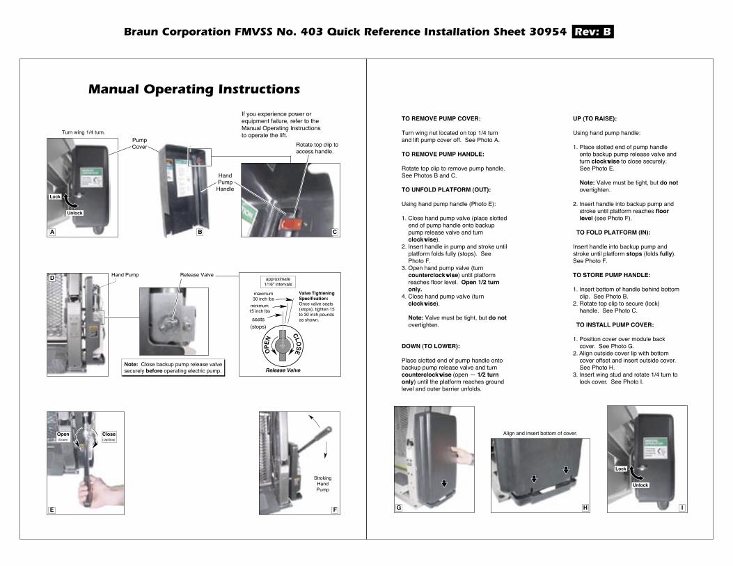
If you experience power orequipment failure, refer to theManual Operating Instructionsto operate the lift.
Open(Down)
Close(Up/Stop)
E
StrokingHandPump
F
�����������������������������
Turn wing 1/4 turn.
Lock
Unlock
HandPump
Handle
PumpCover
DOP
EN
CLOSE
maximum30 inch lbs
minimum15 inch lbs
seats(stops)
approximate1/16" intervals
Valve TighteningSpecification:Once valve seats(stops), tighten 15to 30 inch poundsas shown.
Release ValveNote: Close backup pump release valvesecurely before operating electric pump.
Release ValveHand Pump
Rotate top clip toaccess handle.
A CB
G I
Lock
Unlock
Align and insert bottom of cover.
H
TO REMOVE PUMP COVER:
Turn wing nut located on top 1/4 turnand lift pump cover off. See Photo A.
TO REMOVE PUMP HANDLE:
Rotate top clip to remove pump handle.See Photos B and C.
TO UNFOLD PLATFORM (OUT):
Using hand pump handle (Photo E):
1. Close hand pump valve (place slottedend of pump handle onto backuppump release valve and turnclockwise).
2. Insert handle in pump and stroke untilplatform folds fully (stops). SeePhoto F.
3. Open hand pump valve (turncounterclockwise) until platformreaches floor level. Open 1/2 turnonly.
4. Close hand pump valve (turnclockwise).
Note: Valve must be tight, but do notovertighten.
DOWN (TO LOWER):
Place slotted end of pump handle ontobackup pump release valve and turncounterclockwise (open — 1/2 turnonly) until the platform reaches groundlevel and outer barrier unfolds.
UP (TO RAISE):
Using hand pump handle:
1. Place slotted end of pump handleonto backup pump release valve andturn clockwise to close securely.See Photo E.
Note: Valve must be tight, but do notovertighten.
2. Insert handle into backup pump andstroke until platform reaches floorlevel (see Photo F).
TO FOLD PLATFORM (IN):
Insert handle into backup pump andstroke until platform stops (folds fully).See Photo F.
TO STORE PUMP HANDLE:
1. Insert bottom of handle behind bottomclip. See Photo B.
2. Rotate top clip to secure (lock)handle. See Photo C.
TO INSTALL PUMP COVER:
1. Position cover over module backcover. See Photo G.
2. Align outside cover lip with bottomcover offset and insert outside cover.See Photo H.
3. Insert wing stud and rotate 1/4 turn tolock cover. See Photo I.

Braun Corporation FMVSS No. 403 Quick Reference Installation Sheet 30954 Rev: B
DOWN
DLOF
UP
DLOFN U
Handrail Pivot Pins (2)LO
Parallel ArmPivot Pins (8)
LO
Lift-Tite Latches(Tower Pivot Points - 2)
LO Lift-Tite Latch DampeningSpring (2 springs - 4 Points)
LO
Parallel ArmPivot Pins (8)
LO
Inner Roll Stop (IB)Pivot Points
LO
Outer Barrier HingePivot Points (2)
LO
Outer Barrier Latch LeverLO
Outer Barrier Latch LO
Platform Pivot Pin (2 Points)LO
Platform Fold Axles (2)LO
UHMW Bearing (4)DE
Rotating PivotSlide Arm Pivot Pins
LO
Specified (recommended) Available BraunLubricant Type Lubricant Amount Part No.LO - Light Oil
LG - Light Grease Light Grease Lubriplate 14 oz.(Multipurpose) Can
Light Penetrating Oil LPS2, General Purpose 11 oz.(30 weight or equivalent) Penetrating Oil Aerosol CanStainless Stick Door-Ease 1.68 oz.Style (tube) Stick (tube)
DE - Door-Ease
15807
15806
15805
See the Maintenance/Lubrication Schedule for recommended applications per number of cycles.
���������������������������
Lift-Tite Latch Roller Assemblies (2) LO
�������������������Maintenance andlubrication proceduresmust be performed asspecified by anauthorized servicetechnician. Failure todo so may result inserious bodily injuryand/or propertydamage.
WARNING
������������������������������������
Proper maintenance is necessary to ensure safe,troublefree operation. Inspecting the lift for anywear, damage or other abnormal conditions shouldbe a part of all transit agencies's daily serviceprogram. Simple inspections can detect potentialproblems.
The maintenance and lubrication proceduresspecified in this schedule must be performed by aBraun authorized service representative at thescheduled intervals according to the number ofcycles.
Braun dual parallel arm lifts are equipped withhardened pins and self-lubricating bushings todecrease wear, provide smooth operation andextend the service life of the lift.
When servicing the lift at the recommendedintervals, inspection and lubrication proceduresspecified in the previous sections should berepeated. Clean the components and thesurrounding area before applying lubricants.LPS2 General Purpose Penetrating Oil is recom-mended where Light Oil is called out. Use ofimproper lubricants can attract dirt or othercontaminants which could result in wear or damageto the components. Platform components exposedto contaminants when lowered to the ground mayrequire extra attention.
Lift components requiring grease are lubricatedduring assembly procedures. When these
components arereplaced, grease mustbe applied duringinstallation procedures.Specified lubricants areavailable from TheBraun Corporation (partnumbers providedabove).
All listed inspection,lubrication andmaintenance proceduresshould be repeated at“750 cycle” intervalsfollowing the scheduled“4500 Cycles” maintenance. These intervals are ageneral guideline for scheduling maintenance proce-dures and will vary according to lift use and conditions.Lifts exposed to severe conditions (weather, environ-ment, contamination, heavy usage, etc.) may requireinspection and maintenance procedures to be performedmore often than specified.
Discontinue lift use immediately if maintenance andlubrication procedures are not properly performed, or ifthere is any sign of wear, damage or improper operation.Contact your sales representative or call The BraunCorporation at 1-800-THE LIFT. One of our nationalProduct Support representatives will direct you to anauthorized service technician who will inspect your lift.
Outer barrier hinge pivot points (2)
Outer barrier latch (pivot/slide points)
Outer barrier latch lever pivot points
Lift-Tite™ latches (tower pivot points - 2)
Lift-Tite™ latch gas (dampening) spring pivotpoints (2 springs - 4 points)
Inspect Lift-Tite™ latches and gas springs for wearor damage (bent, deformed or misaligned), positivesecurement (external snap rings) and properoperation
Inspect outer barrier for proper operation
Inspect outer barrier latch for proper operation,positive securement, and detached or missingspring
Apply Light Oil - See Lubrication Diagram
Apply Light Oil - See Lubrication Diagram
Apply Light Oil - See Lubrication Diagram
Apply Light Oil - See Lubrication Diagram
Apply Light Oil - See Lubrication Diagram
Resecure, replace defective parts or otherwisecorrect as needed. Note: Apply Light Grease toLift-Tite™ latch tower pivot point if replacing latch.
Correct or replace defective parts.
Correct or replace defective parts and/orrelubricate. See Lubrication Diagram
���������

Braun Corporation FMVSS No. 403 Quick Reference Installation Sheet 30954 Rev: B
������������������������������������
Inspect lift for wear, damage or any abnormalcondition
Inspect lift for rattles
Correct as needed.
Correct as needed.
Platform pivot pin bearings (2)
Platform fold axles (2)
Inner roll stop (IB) lever bearings (2)
Inner roll stop (IB) lever slot (2)
Rotating pivot slide arm pivot pins (2)
Parallel arm pivot bearings (16)
Handrail pivot pin bearings (4)
Hydraulic cylinder bushings (8)
Inspect Lift-Tite™ latch rollers for wear or damage,positive securement and proper operation (2)
Inspect inner roll stop (IB) for:• Wear or damage• Proper operation. Rollstop should just rest on top
surface of the base plate.• Positive securement (both ends)
Inspect handrail components for wear or damage,and for proper operation
Inspect microswitches for securement and properadjustment.
Make sure lift operates smoothly
Inspect external snap rings:• Handrail pivot pins (2 per pin)• Platform slide/rotate pivot pins (2 per pin)• Platform fold axles (1 per axle)• Inner roll stop (IB) lever bracket pins (1 per pin)• Lift-Tite™ latch gas (dampening) spring (2 per
spring)
Inspect platform fold axles and bearings for wear ordamage and positive securement
Apply Light Oil - See Lubrication Diagram
Apply Light Oil - See Lubrication Diagram
Apply Light Oil - See Lubrication Diagram
Apply Light Oil - See Lubrication Diagram
Apply Light Oil - See Lubrication Diagram
Apply Light Oil - See Lubrication Diagram
Apply Light Oil - See Lubrication Diagram
Apply Light Oil - See Lubrication Diagram
Correct, replace defective parts and/or relubricate.
Resecure, replace or correct as needed. SeePlatform Angle Instructions and MicroswitchAdjustment Instructions.
Replace defective parts.
Resecure, replace or adjust as needed. SeeMicroswitch Adjustment Instructions.
Realign towers and vertical arms. Lubricate orcorrect as needed.
Resecure or replace if needed.
Replace defective parts and resecure as needed.Apply Light Oil.
Perform all procedures listed in previous section also
���������
����������
������������������������������������
Resecure, replace or correct as needed.Remove pump module cover and inspect:• Hydraulic hoses, fittings and connections for wear
or leaks• Harness cables, wires, terminals and connections
for securement or damage• Control board, circuit breaker, power switch and
lights for securement or damage
Resecure, replace or correct as needed
Use Dextron III transmission fluid. Check fluidlevel with platform lowered fully and roll stopunfolded fully. Fill to within 1/2" of the bottom ofthe 1-1/2" fill tube (neck).
Tighten, repair or replace if needed.
Tighten, repair or replace if needed.
Replace if needed.
Tighten or replace if needed.
Replace defective parts and resecure as needed.Apply Light Grease during reassembly procedures.
Replace if needed.
Tighten, replace or correct as needed
Apply Door-Ease or replace if needed. SeeLubrication Diagram.
Resecure or replace if needed.
Resecure, repair or replace if needed.
Check to see that the lift is securely anchored tothe vehicle and there are no loose bolts, brokenwelds, or stress fractures.
Replace decals if worn, missing or illegible.Replace antiskid if worn or missing.
Inspect cotter pins on platform pivot pin (2)
Hydraulic Fluid (Pump) - Check level. Note: Fluidshould be changed if there is visible contamination.Inspect the hydraulic system (cylinder, hoses,fittings, seals, etc.) for leaks if fluid level is low.
Inspect cylinders, fittings and hydraulic connectionsfor wear, damage or leaks
Inspect outer barrier cylinder hose assembly (hose,fasteners, connections, etc.) for wear, damage orleakage
Inspect parallel arms, bushings and pivot pins forvisible wear or damage
Inspect parallel arm pivot pin mounting bolts (8)
Inspect platform pivot pin, bushings and verticalarms for wear, damage and positive securement
Inspect upper/lower fold arms, rotating pivot slidearms, slide support arms and associated pivot pins,bushings, and bearings for visible wear or damage
Inspect gas springs (cylinders) for wear or damage,proper operation and positive securement (IB)
Inspect rotating pivot slide arm UHMW slidebearings (buttons)
Inspect vertical arm plastic covers
Inspect power cable
Mounting
Decals and Antiskid
Perform all procedures listed in previous section also
����������
Repeat all previously listed inspection, lubricationand maintenance procedures at 750 cycleintervals.
�����������������������������
����������