brass-truss™ - dot.state.wy.us · brass-truss™ i nput is based on commands ... section 7 coding...
TRANSCRIPT

Program for the Analysis and Rating of Truss Bridges
BRASS-TRUSS™
Version 2.2
User Manual May 2016
Copyright © 2016 Wyoming Department of Transportation


Disclaimer
Portions of the contents of this system were developed cooperatively by the New York Department of Transportation and the Wyoming Department of Transportation Bridge Program. The New York Department of Transportation and the Wyoming Department of Transportation assume no liability or responsibility for and make no representations or warranties as to applicability or suitability of this computer system. Anyone making use thereof or relying thereon assumes all responsibility and liability arising from such use or reliance. AASHTO Specifications
The Working Stress Analysis (WSD) portions of BRASS-TRUSS™ are current with the AASHTO Specifications for Highway Bridges, Sixteenth Edition - 1996, with Interims. Additional Information and Technical Assistance
Wyoming Department of Transportation Bridge Program 5300 Bishop Boulevard Cheyenne, WY 82009-3340 Telephone: (307) 777-4427 Fax: (307) 777-4279 Web Page: www.dot.state.wy.us/home/engineering_technical_programs/bridge/brass.html FTP Site: ftp://brass:[email protected]
Technical assistance may be obtained from:
Telephone: (307) 777-4489 E-mail: [email protected]
Purchasing, billing and licensing assistance may be obtained from:
Telephone: (307) 777-4489 E-mail: [email protected]
When requesting technical assistance, please visit the incident tracking system at www.wydot-brass.com. Users without an account on the incident tracking system can request an account by clicking on the "Open a Technical Support Account" link/button and e-mailing the address or calling the phone number listed. A username and password will be created and sent to the user. With this system, you may upload your data file and a description of the incident, any error messages, any bridge drawings, and any hand computations, which illustrate the concern. An Incident number will be assigned to track the progress of resolving the incident. 5/16 i BRASS-TRUSS™

8/00 ii BRASS-TRUSS™
How to Use this Manual
The first sections of this manual are designed to act as a self help guide for the novice user and asa reference guide for the more experienced user. In this manual, TRUSS and BRASS all refer toBRASS-TRUSS™.
To the Novice:
Recommended reading is the General Information, (Section 1) and then a brief look through Section3, Typical Commands Sets. Next, thirty minutes or more reviewing the rest of the manual sectionby section is recommended to get an idea of the types of commands available for defining a problem.
One or two commands should be studied in detail noting the format of the command description andthe structure of the command and following parameters. Each problem in TRUSS is made up of aset of commands and associated parameters.
The next step recommended for the novice is to pick out a set of plans for a very simple bridge andcode a set of commands. A structure should be chosen which closely matches one of the TypicalCommand Sets. The description of the Section in which the command resides should be readcarefully. These descriptions are on the first pages of each tabbed Section.
If the above procedure is followed, the novice should be able to assemble a proper command set.If the Command set does not work, contact your BRASS Advisor.
To the User of Previous BRASS Versions:
BRASS-TRUSS™ input is based on commands followed by up to 18 parameters. The parameterscan be integer or floating point (contain a decimal) and need only be separated by a space, columnlocation does not matter so the input is “free format”. Note: BRASS-TRUSS™ uses spaces asdelimiters, not commas like the other BRASS programs. Several of the examples should be studiedto get an idea of how the command structure language appears.
We also suggest you read “To the Novice” preceding this and follow the procedures as necessary.

2/12 iii BRASS-TRUSS™
TABLE OF CONTENTS
TRUSS/GIRDER - FLOORBEAM - STRINGER BRIDGE RATING PROGRAM
Page
SECTION 1 General Information 1.1
SECTION 2 Command Description Index 2.1
SECTION 3 Typical Command Sets 3.1Girder, Floorbeam, Stringer Bridges 3.1Truss, Floorbeam, Stringer Bridges 3.2
- INPUT COMMANDS -
SECTION 4 Coding Instructions for Bridge Summary, Live Loads and Allowable Stresses 4.1
General Information 4.1Spans Command 4.2Date Command 4.4Bridge Command 4.6Location Command 4.10Years Command 4.12Truck-Code Command (Not yet operational) 4.14Stresses Command 4.16Comments Command 4.18
SECTION 5 Coding Instructions for Roadway Details 5.1Wearing Surface Command 5.2Pavement Command 5.4Left Sidewalk Command 5.6Right Sidewalk Command 5.10Median Command 5.14
SECTION 6 Coding Instructions for Railway and Utilities Details 6.1Member Layout Command 6.2Railway Command 6.4Track Layout Command 6.6Utilities Command 6.8
SECTION 7 Coding Instructions for Deck Cross-section & Sleepers 7.1General Information 7.1Concrete Deck Command 7.2Grating Deck Command 7.6Timber Deck Command 7.8Steel Sleepers Command 7.10Timber Sleepers Command 7.12

2/12 iv BRASS-TRUSS™
SECTION 8 Coding Instructions for Secondary Members - Stringers 8.1Secondary Member Longitudinal Stringer Command 8.2Left Sidewalk Stringer Command 8.4Right Sidewalk Stringer Command 8.6Concrete Protection Longitudinal Stringer Command 8.8Channel Stringer Fascia and Interior Command 8.10Rolled Stringer Fascia and Interior Command 8.12Timber Stringer Fascia and Interior Command 8.14
SECTION 9 Coding Instruction for Secondary Members - Floorbeams 9.1Secondary Member Transverse Floorbeam Command 9.2Concrete Protection Transverse Floorbeam Command 9.4Channel Floorbeam End and Intermediate Command 9.6Rolled Floorbeam End and Intermediate Command 9.8Isec Floorbeam End and Intermediate Command 9.10
SECTION 10 Coding Instructions for Main Members - Trusses 10.1General Information for Trusses 10.1General Deterioration Information for Truss Members 10.5Main Member Command 10.6Continuous Truss Supports Command 10.8CBX or CBH Command - Box (Channels & Plates) 10.12ABX or ABH Command - Box (Angles & Plates) 10.16ROLLED or ROLHED Command - Rolled Beam & Plates 10.20ISEC or ISEH Command - I - Section (Plates & Angles) 10.24EYEBAR or EYEHAR Command - Eyebar 10.28THREADED or THRHADED Command - Threaded Bar 10.32
SECTION 11 Coding Instructions for - Main Members - Girders 11.1General Deterioration Information for Girder Members 11.1Main Member Command 11.2Hinge Command 11.6Main Member Concrete Protection Command 11.8Riveted Command 11.10Rolled Command 11.14Welded Command 11.18Channel Command 11.20Timber Command 11.22
SECTION 12 Coding Instructions for Connections 12.1Connection Command 12.2Framed Details Command 12.4Hanger Details Command 12.8Hinge Details Command 12.10
SECTION 13 Deterioration Information 13.1
SECTION 14 Sample Problem 14.1

7/99 1.1 BRASS-TRUSS™
TRUSS/GIRDER - FLOORBEAM - STRINGER BRIDGE RATING PROGRAM
1. GENERAL INFORMATION BRASS-TRUSS™ is a system of computer programs designedto assist a bridge engineer in the analysis and load rating of simple or continuous truss or girderbridges with floorbeams and stringers. It generates properties, computes truss coordinates andweights, analyzes each simple or continuous span for dead load and live load moments and shears,and determines the structural rating for each type of member submitted. This component wasoriginally developed by the New York Department of Transportation.
The following is a list of items describing some of the internal procedures and assumptions used inBRASS-TRUSS™ :
1. The effective column length factor, K is 0.875 for pinned truss member ends and 0.75 forriveted, welded or bolted ends. These values are from AASHTO, Standard Specificationsfor Highway Bridges 1996, Appendix C, Page 635. They are set in Subroutine RDGTRS.
2. To account for the weight of miscellaneous hardware and minor structural items such asgusset plates, BRASS-TRUSS™ adds 70 percent more weight per foot to each trussmember (not including stringers or floorbeams). This is set in Subroutine RDGTRS.
3. To calculate the dead load of the truss to apply to a panel point, BRASS-TRUSS™ addsone half of the panel dead load on each side of the panel point.
4. The live loads automatically applied by BRASS-TRUSS™ are HS20 truck and lane, H20truck and lane, Type 3, Type 3S3, and Type 3-3 as described in AASHTO Manual forMaintenance Inspection of Bridges 1983, Page 50. A future enhancement will allow liveloads to be selected from the truck library “TRUCK.BLB”. This library may be modifiedusing the UTIL.EXE utility program as described in Chapter 15. THIS CAPABILITY ISNOT YET OPERATIONAL.
5. For all members (except truss chords) the allowable stress for inventory is the input stressmultiplied by 0.55 and for operating 0.75.
6. The program does not include any dead load for handrails, curbs or lateral bracing otherthan the addition of 70% to all truss member weights.
7. BRASS-TRUSS™ rounds rating tonnages down to the nearest whole ton.
8. BRASS-TRUSS™ only rates an interior stringer. If more than one intermediate floorbeamis input, BRASS-TRUSS™ will only rate the last floorbeam entered in the Command Set.
9. BRASS-TRUSS™ uses input timber dimensions.
10. The length of stringers must be equal to or a multiple of the panel length, ±10 percent.
11. BRASS-TRUSS™ will only rate at mid-span for simple span girder-floorbeam systems.
12. Floorbeams are rated at mid-span and are assumed to be simple spans.

8/00 1.2 BRASS-TRUSS™
13. BRASS-TRUSS™ considers the wearing surface on a concrete deck a superimposed deadload and divides it equally to all stringers. The weight per foot of the concrete deck appliedto a stringer is the stringer spacing multiplied by the deck depth in feet times 0.150.
The following types of structures may be rated by this component.
(1) Steel Girders - Simple or up to 8 spans continuous
(a) Deck Girders (up to 3 Main Members* per Rating Unit)! There must be 3 or less Main Members in the Bridge Cross-section.! Floorbeams (up to 4 per Rating Unit)**! Stringers (up to 4 per Rating Unit) ! Sleepers (up to 2 per Rating Unit) ! Connections (up to 4 per Rating Unit)
(b) Thru Girders (up to 3 Main Members* per Rating Unit)! There must be 3 or less Main Members in the Bridge Cross-section.! Floorbeams (up to 4 per Rating Unit)**! Stringers (up to 4 per Rating Unit) ! Sleepers (up to 2 per Rating Unit) ! Connections (up to 4 per Rating Unit)
(2) Steel Trusses (Simple or up to 13 spans continuous)! There must be 3 or less Main Members* in the Bridge Cross-section.
(a) Deck Trusses (up to 3 Main Members* Per Rating Unit) ! Floorbeams (up to 4 per Rating Unit)**! Stringers (up to 4 per Rating Unit) ! Sleepers (up to 2 per Rating Unit) ! Connections (up to 4 per Rating Unit)
(b) Pony Trusses (up to 3 Main Members* per Rating Unit) ! Floorbeams (up to 4 per Rating Unit)**! Stringers (up to 4 per Rating Unit) ! Sleepers (up to 2 per Rating Unit) ! Connections (up to 4 per Rating Unit)
(c) Thru Trusses (up to 3 Main Members* per Rating Unit) ! Floorbeams (up to 4 per Rating Unit)**! Stringers (up to 4 per Rating Unit) ! Sleepers (up to 2 per Rating Unit) ! Connections (up to 4 per Rating Unit)
* A “Main Member” is defined as the truss unit as a whole or the main steel girder (Deck or Thru). In the event the left or right (or middle) trusses or girders differ, BRASS allows the user to input a maximum of 3 Main Members.** Only the last floorbeam entered in the Command Set will be rated
All directions of "LEFT" and "RIGHT", or "SPAN" number, “AHEAD”, “BACK” etc. must agreewith the Bridge Inventory and Inspection data for orientation purposes.

7/99 1.3 BRASS-TRUSS™
The decision to submit more than one main member on a truss/girder span of a bridge may be madeby the engineer, using the following criteria. If both main members have the same configuration andhave no rust deterioration, then only one main member and required additional members are to besubmitted for each span. For cases where deterioration is present in one or both of the mainmembers of this type of structure then both main members are to be submitted.
Two stringers, one fascia and one interior, and two floorbeams, one end and one intermediate, areexpected in each data set, however, the fascia stringer and the end floorbeam are not rated. They areshown in the output for information purposes only. The only reason for any omissions would be formembers that do not exist.
Dimension values used are the normal engineering units, in the English System, that are used to sizethe particular part of the bridge under consideration. Roadway widths, member lengths, spans, etc.,are understood to be in feet. Roadway thickness, member cross section data, etc., are understoodto be in inches. The section dimensions measured should be of original unrusted or nondeterioratedsections as determined by the engineer in the field. The tolerances for dimensioning are as follows:
Timber members Nearest 0.25 inches
Concrete members Nearest 0.50 inches
Asphalt Surfacing Nearest 0.50 inches
Steel Rolled Sections Nearest 0.10 inches (Widths & Depths)and Plates Nearest 0.05 inches (Thickness)
Span Lengths andRoadway Dimensions Nearest 0.1 feet
Deck Span Lengths Nearest 0.05 feet
Input Format
The commands guide the user in building an ASCII data file. This data file is developed in acommand format. Each line begins with a Bridge Identification Number (BIN) followed by acommand which describes up to 18 data entries hereinafter referred to as parameters.
The data may be entered as a real (including a decimal), integer (excluding a decimal point) or analpha character. Zero is not the same as a blank. Alpha characters are case sensitive. Default entriesare given by omission of the command in those cases where all default values are desired.
To facilitate database functionality, the “BRIDGE INDENT. NUMBER” field must be used with allcommands. This numeric field must contain 7 characters and must be greater than 1000000.
Spaces, NOT COMMAS, are used to delineate parameters. The number of spaces betweenparameters has no meaning, however, do not use tabs to separate entries. For example, if the thirdentry of a command is the only entry required, any of the following would be valid.

8/00 1.4 BRASS-TRUSS™
1000000 COMMAND-EXAMPLE 0 0 2.01000000 COMMAND-EXAMPLE 0 0 2
When a command is used, all parameters must be entered. No parameter may be left blank. If aparameter does not apply, enter zero. Data may be entered anywhere after a command with orwithout decimal points in the case of whole numbers. A blank space must separate the commandand all parameters. No more than 132 columns per line may be input.
Executing BRASS-TRUSS™
BRASS-TRUSS™ is basically a DOS based application. A Microsoft Windows™ Graphical UserInterface has not yet been developed. BRASS-TRUSS™ can be run outside the Windows™environment or as a DOS shell within Windows™. BRASS-TRUSS™ consists of two executableprograms (RATINGED.EXE and RATINGST.EXE), a section library file (STSECT.DAT), andother utility files (TRUSS.PIF, R_EDITS.DAT, etc.).
Running BRASS-TRUSS™ is a two step process. First, the user screens the data set for errors,then chooses an analysis procedure. There are two types of analysis procedures available. Pages 3.1through 3.2 of the Users Manual detail the commands required for a girder-floorbeam-string bridgeand a truss-floorbeam-stringer bridge.
From Windows™, double click the BRASS-TRUSS™ icon. This action will place you at the‘c:\truss\exe>’ prompt. At the prompt, type ‘ratinged’. BRASS-TRUSS™ will automaticallyprompt you for the input file name (i.e. filename.dat) and will assign the output file name (i.e.filename.out). (Optionally, you may enter ‘ratinged filename.dat’ to bypass the screen prompt.) The ‘ratinged’ command will check the validity of the input data set, look for missing requiredcommands, check the ranges of key values, and look for many common errors in the input data set.There are two classifications of errors reported by ratinged - “FATAL EDITS” and “NON-FATALEDITS”. When ratinged detects a serious error or omission which would prevent execution, a“FATAL EDIT” error message will be placed in the output file and the user will be unable toperform a girder or truss analysis. When ratinged detects a particular value which is entered wrongor may be out of an acceptable range, a “NON-FATAL EDIT” error message may be printed. At thispoint the engineer may continue analysis or correct the error.
If ratinged is successful, BRASS-TRUSS™ will create three files: filename.out, filename.te1, andfilename.pas. If ratinged is not successful, BRASS-TRUSS™ will create: filename.out,filename.te1, and filename.err to help you debug the file. Note: BRASS-TRUSS™ will notoverwrite an existing output. Therefore, you will need to delete filename.out and filename.te1 (orrename filename.out to another filename) before re-running ratinged. Temporary files such asfilename.PAS, filename.FRC, etc. are created and deleted as TRUSS runs.
The second part of running BRASS-TRUSS™ is selecting the desired analysis engine. To analyzea stringer-floorbeam-truss system, enter ‘ratingst’ at the ‘c:\truss\exe>’ prompt. To analyze a girder-floorbeam-stringer system, enter ‘ratingsg’ at the ‘c:\truss\exe>’ prompt. Either analysis methodwill prompt the user for the same input data set filename and will append the results to the existingoutput file. (Optionally, you may enter ‘ratingst filename.dat’ or ‘ratingsg filename.dat’ to bypassthe screen prompt.)

5/05 1.5 BRASS-TRUSS™
Bugs, Gremlins and Other Problems
Inevitably, every user will have an input data set that will not run properly. Based on pastexperience, approximately 90% of all problem logs are user error. Naturally, this should be the firstplace to look when BRASS won’t run. A lot of error and warning messages have been written intothe source code to handle the most common errors. It is nearly impossible to anticipate every errorwhich may occur. When searching for coding errors, check the output file and/or screen messagesfor clues to the problem.
Common error messages are Math Error or Divide by Zero Error. These messages usually indicatethat some required data was not input. Check your input data set for omissions.If you cannot resolve the problem, you can request technical assistance using the procedures listedon page i.

5/05 1.6 BRASS-TRUSS™
The BRASS™ Suite
BRASS™ is a suite of programs that assists the engineer in many aspects of bridge design and rating. Theseprograms are described below:
BRASS-GIRDER™ Performs a design review and/or rating of highway bridges decks and girders usingplane frame analysis and the AASHTO Standard Specifications. Load factor and working stresscomputations are performed. BRASS-GIRDER(LRFD)™ -- A comprehensive system for the design and/or rating of highway bridgesdecks and girders using finite element theory of analysis and current AASHTO LRFD Specifications.
BRASS-PIER™ -- Performs an analysis of a bridge transverse section at pier locations. The programprovides a comprehensive analysis of bridge decks, piers, and selected foundation types. All AASHTO loadsand group loads are considered. Live load is automatically positioned for maximum actions. Load factorand working stress computations are performed.
BRASS-PIER(LRFD)™ -- Performs analysis of a bridge transverse section at pier locations. Provides acomprehensive analysis of bridge decks, piers, and selected foundation types. All AASHTO (LRFD) loadsand group loads are considered. Live load is automatically positioned for maximum actions.
BRASS-CULVERT™ -- Designs, analyzes, and/or rates one, two, three, or four barrel reinforced concreterigid or flexible box culverts, with or without bottom slab. End skews can also be defined. Wall and slabthickness may be specified or the program will set the thickness. AASHTO guidelines are followed andService Load Design, Load Factor Design, or Load and Resistance Factor Design may be specified. Membercapacities are designed based on applied truck load, soil fill, self weight and water pressure. StandardAASHTO and user defined truck loadings can be specified. Output generated by the program includes:culvert geometry; moments, shears, and axial forces at tenth points; stresses; required area of reinforcement;steel design table; splice length; weights and volumes of steel and concrete; and influence ordinates. Criticaldesign moments, shears, and axial forces for each member are summarized.
BRASS-SPLICE™ -- Performs the design of field splices for rolled beam or welded plate steel girders.Design criteria are in compliance with the AASHTO Load Factor Design Standard Specifications andWYDOT design practice.
BRASS-POLE™ -- Performs a working stress analysis of cantilever sign, luminaire and signal supportstructures. Round or polygonal steel poles may be analyzed according to the AASHTO StandardSpecifications.
BRASS-DIST™ -- Performs a finite-strip element analysis to determine the factor for wheel loaddistribution for any axle spacing or width and any tire configuration of a truck placed at any position on thebridge deck. Standard trucks may also be used. NOTE: AASHTO formulas are based on empirical data andare applicable to six foot axle widths. BRASS-DIST™ will also give results for a simple beam "deck-to-girder" analysis for dead loads.
BRASS-PAD™ -- Performs analysis and design of steel or fabric reinforced elastomeric bearingpads according to the AASHTO Standard or LRFD Specifications.

7/99 2.1 BRASS-TRUSS™
2. COMMAND DESCRIPTION INDEX (In Alphabetical Order)
Command Name Command No. Page No.
BRIDGE . . . . . . . . . . . . . . . . . . . . . . . . . . . . . . . . . . . . . . . 30 4.6
COMMENTS . . . . . . . . . . . . . . . . . . . . . . . . . . . . . . . . . . . 80 4.18
CONCRETE PROTECTIONLongitudinal Stringer . . . . . . . . . . . . . . . . . . . . . . 260 8.8Main Member-Girder . . . . . . . . . . . . . . . . . . . . . . 450 11.8Transverse Floorbeam . . . . . . . . . . . . . . . . . . . . . 310 9.4
CONNECTIONSConnection . . . . . . . . . . . . . . . . . . . . . . . . . . . . . . 510 12.2Framed Details . . . . . . . . . . . . . . . . . . . . . . . . . . . 520 12.4Hanger Details . . . . . . . . . . . . . . . . . . . . . . . . . . . 530 12.8Hinge Details . . . . . . . . . . . . . . . . . . . . . . . . . . . . 540 12.10
DATE . . . . . . . . . . . . . . . . . . . . . . . . . . . . . . . . . . . . . . . . 20 4.4
DECKConcrete . . . . . . . . . . . . . . . . . . . . . . . . . . . . . . . . 180 7.2Grating . . . . . . . . . . . . . . . . . . . . . . . . . . . . . . . . . 290 7.6Timber . . . . . . . . . . . . . . . . . . . . . . . . . . . . . . . . . 200 7.8
DETERIORATION . . . . . . . . . . . . . . . . . . . . . . . . . . . . . . 13.1
FLOORBEAMSChannel . . . . . . . . . . . . . . . . . . . . . . . . . . . . . . . . 320 9.6I-Sec. . . . . . . . . . . . . . . . . . . . . . . . . . . . . . . . . . . 340 9.10Rolled . . . . . . . . . . . . . . . . . . . . . . . . . . . . . . . . . . 330 9.8
GIRDERSChannel . . . . . . . . . . . . . . . . . . . . . . . . . . . . . . . . 490 11.20Riveted . . . . . . . . . . . . . . . . . . . . . . . . . . . . . . . . . 460 11.10Rolled . . . . . . . . . . . . . . . . . . . . . . . . . . . . . . . . . . 470 11.14Timber . . . . . . . . . . . . . . . . . . . . . . . . . . . . . . . . . 500 11.22Welded . . . . . . . . . . . . . . . . . . . . . . . . . . . . . . . . . 480 11.18
LOCATION . . . . . . . . . . . . . . . . . . . . . . . . . . . . . . . . . . . . 40 4.10
MAIN MEMBERSGirder . . . . . . . . . . . . . . . . . . . . . . . . . . . . . . . . . . 430 11.2Hinge . . . . . . . . . . . . . . . . . . . . . . . . . . . . . . . . . . 440 11.6Truss . . . . . . . . . . . . . . . . . . . . . . . . . . . . . . . . . . . 350 10.6Continuous Truss Supports . . . . . . . . . . . . . . . . . 360 10.8
MEDIAN . . . . . . . . . . . . . . . . . . . . . . . . . . . . . . . . . . . . . 130 5.14
MEMBER LAYOUT . . . . . . . . . . . . . . . . . . . . . . . . . . . . 140 6.2
PAVEMENT . . . . . . . . . . . . . . . . . . . . . . . . . . . . . . . . . . 100 5.4

7/99 2.2 BRASS-TRUSS™
2. COMMAND DESCRIPTION INDEX (Cont.)
Command Name Command No. Page No.
RAILWAY . . . . . . . . . . . . . . . . . . . . . . . . . . . . . . . . . . . . 150 6.4
SECONDARY MEMBERLongitudinal Stringer . . . . . . . . . . . . . . . . . . . . . . 230 8.2Transverse Floorbeam . . . . . . . . . . . . . . . . . . . . . 300 9.2
SIDEWALKSLeft . . . . . . . . . . . . . . . . . . . . . . . . . . . . . . . . . . . . 110 5.6Right . . . . . . . . . . . . . . . . . . . . . . . . . . . . . . . . . . . 120 5.9
SLEEPERSSteel . . . . . . . . . . . . . . . . . . . . . . . . . . . . . . . . . . . 210 7.10Timber . . . . . . . . . . . . . . . . . . . . . . . . . . . . . . . . . 220 7.12
SPANS . . . . . . . . . . . . . . . . . . . . . . . . . . . . . . . . . . . . . . . . 10 4.2
STRESSES . . . . . . . . . . . . . . . . . . . . . . . . . . . . . . . . . . . . . 70 4.16
STRINGERSChannel . . . . . . . . . . . . . . . . . . . . . . . . . . . . . . . . 270 8.10Rolled . . . . . . . . . . . . . . . . . . . . . . . . . . . . . . . . . . 280 8.12Sidewalk
Left . . . . . . . . . . . . . . . . . . . . . . . . . . . . . . . . . 240 8.4Right . . . . . . . . . . . . . . . . . . . . . . . . . . . . . . . . 250 8.6
Timber . . . . . . . . . . . . . . . . . . . . . . . . . . . . . . . . . 290 8.14
TRACK LAYOUT . . . . . . . . . . . . . . . . . . . . . . . . . . . . . . 160 6.6
TRUCK-CODE (Not currently operational) . . . . . . . . . . . 60 4.14
TRUSS MEMBERSBox (Angles & Plates) . . . . . . . . . . . . . . . . . . . . . 380 10.16Box (Channels & Plates) . . . . . . . . . . . . . . . . . . . 370 10.12Eyebar . . . . . . . . . . . . . . . . . . . . . . . . . . . . . . . . . 410 10.28Isec . . . . . . . . . . . . . . . . . . . . . . . . . . . . . . . . . . . . 400 10.24Rolled . . . . . . . . . . . . . . . . . . . . . . . . . . . . . . . . . . 390 10.20Threaded . . . . . . . . . . . . . . . . . . . . . . . . . . . . . . . 420 10.32
UTILITIES . . . . . . . . . . . . . . . . . . . . . . . . . . . . . . . . . . . . 170 6.8
WEARING SURFACE . . . . . . . . . . . . . . . . . . . . . . . . . . . 90 5.2
YEARS . . . . . . . . . . . . . . . . . . . . . . . . . . . . . . . . . . . . . . . 50 4.12

7/99 3.1 BRASS-TRUSS™
3. TYPICAL COMMAND SETS
3.1 GIRDER, FLOORBEAM, STRINGER BRIDGES - RATINGSG.EXE
Command Name Usage
SPANS RequiredDATE OptionalBRIDGE RequiredLOCATION RequiredDEBUG OptionalYEARS RequiredTRUCK-CODE (Not currently operational) OptionalSTRESSES RequiredCOMMENTS OptionalWEARING SURFACE RequiredPAVEMENT RequiredLEFT SIDEWALK RequiredRIGHT SIDEWALK RequiredMEDIAN OptionalMEMBER LAYOUT OptionalRAILWAY OptionalTRACK LAYOUT OptionalUTILITIES OptionalCONCRETE DECKGRATING DECK Req'd *TIMBER DECKSTEEL SLEEPERS OptionalTIMBER SLEEPERS OptionalSECONDARY MEMBER LONGITUDINAL STRINGER Required**LEFT SIDEWALK STRINGER OptionalRIGHT SIDEWALK STRINGER OptionalCONCRETE PROTECTION - LONGITUDINAL STRINGER OptionalCHANNEL STRINGER - FASCIA OR INTERIORROLLED STRINGER - FASCIA OR INTERIOR Req'd.***TIMBER STRINGER - FASCIA OR INTERIORSECONDARY MEMBER TRANSVERSE FLOORBEAM RequiredCONCRETE PROTECTION - TRANSVERSE FLOORBEAM OptionalCHANNEL FLOORBEAM - END OR INTERMEDIATEROLLED FLOORBEAM - END OR INTERMEDIATE Req’d ***ISEC FLOORBEAM - END OR INTERMEDIATEMAIN MEMBER - GIRDER RequiredMAIN MEMBER - CONCRETE PROTECTION OptionalRIVETEDROLLEDWELDED Req'd.***CHANNELTIMBERCONNECTION OptionalFRAMEDHANGER OptionalHINGE
* Only one command from this group can be used in a single data set.** This command is required when a stringer is present.*** At least one command from this group must be used in each data set.3.2 TRUSS, FLOORBEAM, STRINGER BRIDGES - RATINGST.EXE

7/99 3.2 BRASS-TRUSS™
Command Name Usage
SPANS RequiredDATE OptionalBRIDGE RequiredLOCATION RequiredDEBUG OptionalYEARS RequiredTRUCK-CODE (Not currently operational) OptionalSTRESSES RequiredCOMMENTS OptionalWEARING SURFACE RequiredPAVEMENT RequiredLEFT SIDEWALK RequiredRIGHT SIDEWALK RequiredMEDIAN OptionalMEMBER LAYOUT OptionalRAILWAY OptionalTRACK LAYOUT OptionalUTILITIES OptionalCONCRETE DECKGRATING DECK Req'd. *TIMBER DECKSTEEL SLEEPERS OptionalTIMBER SLEEPERS OptionalSECONDARY MEMBER LONGITUDINAL STRINGER Required**LEFT SIDEWALK STRINGER OptionalRIGHT SIDEWALK STRINGER OptionalCONCRETE PROTECTION - LONGITUDINAL STRINGER OptionalCHANNEL STRINGER - FASCIA OR INTERIORROLLED STRINGER - FASCIA OR INTERIOR Required***TIMBER STRINGER - FASCIA OR INTERIORSECONDARY MEMBER TRANSVERSE FLOORBEAM RequiredCONCRETE PROTECTION - TRANSVERSE FLOORBEAM OptionalCHANNEL FLOORBEAM - END OR INTERMEDIATEROLLED FLOORBEAM - END OR INTERMEDIATE Required***ISEC FLOORBEAM - END OR INTERMEDIATEMAIN MEMBER - TRUSS RequiredCONTINUOUS TRUSS SUPPORTS OptionalCBX ABXROLLED Required***ISECEYEBARTHREADEDCONNECTION OptionalFRAMEDHANGER OptionalHINGE
* Only one command from this group can be used in a single data set.** This command is required when a stringer is present.*** At least one command from this group must be used in each data set.

7/99 4.1 BRASS-TRUSS™
4. CODING INSTRUCTIONS FOR BRIDGE SUMMARY, LIVE LOADS ANDALLOWABLE STRESSES
4.1 GENERAL INFORMATION
These commands are intended to provide a record of the total number of spans on this project andwhat span, if any, were rated. Each span (or multiple rating unit) is identified and it is noted howthe span was rated. If it was not rated, a code is placed to explain the reason the unit could not berated.
A rating unit is defined as a single span or a multi-span continuous structure that the program canhandle as one unit.
These commands also specify the live load and allowable stresses.

7/99 4.2 BRASS-TRUSS™
10 BRASS-TRUSS™ COMMAND DESCRIPTION
COMMAND NAME SPANS
PURPOSE
This command defines the ramp attachment and the totalnumber of spans or rating units to be rated. This command isrequired.
REMEMBER: All commands must be preceded by a seven digitnumeric Bridge Identification Number, greater than 1000000,followed by a space.
3 COMMAND PARAMETERS
Span NumberRamp Bridge Only
For a ramp bridge only, enter the Main Bridge span number thatthe ramp is attached to. If there are no ramps, enter 0.
Ramp LetterRamp Bridge Only
For a ramp bridge only, enter the ramp letter designation for theparticular ramp span to be rated. If there are no ramps, enter 0.
Total Bridge Spans Enter the total number of spans on the bridge, viaduct, etc. Thisparameter cannot be 0 (Zero). If fictitious additional spans areneeded to input a bridge, keep this number equal to the actualNumber of Spans in the bridge.

7/99 4.3 BRASS-TRUSS™
EXAMPLE
1234567 SPANS 0 0 1
FIGURES
NOTES

7/99 4.4 BRASS-TRUSS™
20 BRASS-TRUSS™ COMMAND DESCRIPTION
COMMAND NAME DATE
PURPOSE This command allows the user to record up to 4 inspectiondates. This command is optional.
4 COMMAND PARAMETERS
Date #1Format = mm/yy
Enter the month and year the bridge was inspected. Thesedates are for recording purposes only and are Y2K Compliant.
Date #2 Enter the month and year the bridge was inspected.
Date #3 Enter the month and year the bridge was inspected.
Date #4 Enter the month and year the bridge was inspected.

7/99 4.5 BRASS-TRUSS™
EXAMPLE
1234567 DATE 10/78 8/82 9/85 5/87
FIGURES
NOTES

8/00 4.6 BRASS-TRUSS™
30 BRASS-TRUSS™ COMMAND DESCRIPTION
COMMAND NAME BRIDGE
PURPOSE This command defines the spans and members to be rated. Italso defines the member type. This command is required.
12 COMMAND PARAMETERS
Beginning Span Number Enter the span number of the first span in the unit that is beingrated.
Ending Span Number Enter the span number of the last span in the unit that is beingrated. For simple spans, enter the same span number as enteredin the previous parameter.
Beginning Span IdenticalUnits
If there are any other spans or rating units that are identical tothe unit being rated, enter the beginning span number of thatunit or series of units. It will not be necessary to rate thesespans separately. If none exist, enter 0.
Ending Span Identical Units If there are any other spans or rating units that are identical tothe unit being rated, enter the ending span number of that unitor series of units. If there is only one span, enter the same spannumber as entered in the previous parameter. If 0 was enteredin the previous parameter, enter 0 here also.
Main Member Type Enter “ARCH”, “CULVERT”, “FRAME”, “GIRDER”,“SUSPEN”, “BOX”, “I-BEAM”, “T-BEAM”, “SLAB” or“TRUSS”. The word “GIRDER” includes Rolled Beams asmain members. No other words are acceptable. See Note onPage 1.2 for the definition of “Main Member”.
Design Type Enter “S” or “C” to indicate a simple span or a continuous spanrating unit. No other letters are acceptable. Any othercharacters will generate a Fatal Edit Message which will stopthe run.
Number of Main Members tobe Rated
(Continued)
Enter the number of main members to be rated. Up to threemain members are allowed. The presence of a number in thisparameter indicates that commands are included in the data setfor this rating unit. If the main member data for the unit is notsubmitted, enter the appropriate Non-Rating Code. (See Notes)

7/99 4.7 BRASS-TRUSS™
COMMAND PARAMETERS (Cont.)
Number of End Floorbeams Enter the number of end floorbeams. A total of four floorbeams(end and interior combined) are allowed. If the stringers restdirectly on the abutment, enter 0. If none are present, enter 0.If the floorbeam data is not submitted, enter the appropriateNon-Rating Code. (See Notes)
Number of InteriorFloorbeams
Enter the number of interior floorbeams to be rated. A total offour floorbeams (end and interior combined) are allowed. If thefloorbeam data is not submitted, enter the appropriate Non-Rating Code. (See Notes)
Number of Exterior (Fascia)Stringers
Enter the number of exterior (fascia) stringers. A total of fourstringers (fascia and interior combined) are allowed. If the slabrests on a shelf angle on the main member of a “THRUGIRDER” bridge, enter 0. For a multigirder unit, or if noneexist, enter 0. If the stringer data is not submitted, enter theappropriate Non-Rating Code. (See Notes)
Number of Interior Stringers Enter the number of interior stringers to be rated. A total of fourstringers (fascia and interior combined) are allowed. If the slabrests on a shelf angle on the main member of a “THRUGIRDER” bridge, enter 0. For a multigirder unit, or in noneexist, enter 0. If the stringer data is not submitted, enter theappropriate Non-Rating Code. (See Notes)
Number of Connections Enter the number of connections. Up to four connections areallowed. For multigirder or concrete units, enter 0. If theconnection data is not submitted, enter the appropriate Non-Rating Code. Connections cannot be rated. (See Notes)

7/99 4.8 BRASS-TRUSS™
EXAMPLE
For a simple span truss with three main members, one end floorbeam, one interior floorbeam,one exterior stringer, one interior stringer, and an unknown connection configuration, code:
1234567 BRIDGE 1 1 0 0 TRUSS S 3 1 1 1 1 UNKN
FIGURES
NOTES
NON-RATING CODES
UNRA - UNRATABLE STRUCTURAL TYPEUse this code if the member cannot be rated by this program, such as suspension bridges,curved girders, rigid frames, arches or post-tensioned bridges.
SEVE - SEVERE DETERIORATIONUse this code if the member is severely deteriorated so that it is beyond the scope of theproject to accurately rate the member. (This code is to be used only for extreme cases ofdeterioration.)
INAC - INACCESSIBLE MEMBERUse this code if the member is inaccessible and cannot be measured, such as a memberover electrified wires.
UNKN - UNKNOWN SECTION PROPERTIESUse this code when plans are not available and the member cannot be measured becauseof embedment in concrete, blast protection coverage or some similar situation.

7/99 4.9 BRASS-TRUSS™
8/00 4.10 BRASS-TRUSS™
40 BRASS-TRUSS™ COMMAND DESCRIPTION
COMMAND NAME LOCATION
PURPOSEThis command defines the span to be rated and data to describethe location of the structure. This command is required.See Notes.
6 COMMAND PARAMETERS
Span Number Enter the span number being rated. For continuous structures,use the first span of the continuous unit. When a ramp span isbeing rated, enter the span number of the main bridge spanwhere the ramp span joins onto or separates from the mainbridge.
Ramp Letter Enter the ramp letter. If no ramps exist, enter 0.
Ramp Span Number If ramp letter is 0, enter 0 here. Otherwise enter the spannumber for the ramp span that is being rated.
District & County Number Enter the district number in the first digit of this two digitnumeric parameter and the county number in the next digit.Only two digits are allowed.
Route Number Enter the Interstate, U.S., State, County or City Highwaynumbers and letter, if present, for bridges carrying highwaytraffic. Enter the railroad initials, (UPRR, BNRR, etc.) forbridges carrying railway traffic. If none of these are available,enter 0. Only four letters and/or digits are allowed, hyphens arenot allowed.
Consultant Code Enter the consultant code. This must be a Letter (A-Z) followedby a number (00-99).

7/99 4.11 BRASS-TRUSS™
EXAMPLE
1234567 LOCATION 1 0 0 46 0 R04
FIGURES
NOTES
Each LOCATION command must correspond to a ‘BRIDGE’ record previously defined. Ifthere are 3 ‘BRIDGE’ records, there must be 3 ‘LOCATIONS’. In this manner, several ratingunits can be run together in a single input data set.

7/99 4.12 BRASS-TRUSS™
50 BRASS-TRUSS™ COMMAND DESCRIPTION
COMMAND NAME YEARS
PURPOSEThis command defines the year of original construction and theyears replacement of members were performed. These fourdigit years are used to define the allowable yield strength in themembers. This command is required.
5 COMMAND PARAMETERS
Year of Original Construction Enter the 4-digit year taken from erection plans, bridgesuperstructure plans, inventory file or other informationconsidered to be reliable for the superstructure.
Replacement Dates, Deck If the deck, including sleepers (if needed) were replaced, enterthe 4-digit year of construction of the latest deck replacement.Otherwise enter 0. (See Notes)
Replacement Dates, Stringers If the stringers were replaced, enter the 4-digit year ofconstruction of the latest stringer replacement. Otherwise enter0. (See Notes)
Replacement Dates,Floorbeams
If the floorbeams were replaced, enter the 4-digit year ofconstruction of the latest floorbeam replacement. Otherwiseenter 0. (See Notes)
Replacement Dates,Main Members
If the main members were replaced, enter the 4-digit year ofconstruction of the latest main member replacement. Otherwiseenter 0. (See Notes)

7/99 4.13 BRASS-TRUSS™
EXAMPLE
1234567 YEARS 1923 1942 0 0 0
FIGURES
NOTES
If years are input for replacement dates, the default values for yield stresses will override any valueentered in the STRESSES command.

7/99 4.14 BRASS-TRUSS™
60 BRASS-TRUSS™ COMMAND DESCRIPTION
COMMAND NAME TRUCK-CODE
PURPOSE
NOTE: This command is not yet operational.
This command defines truck loads by a “truck code”. This truckcode must have been previously stored in the Truck Libraryalong with axle weight and spacing data defining the truck. Seecommand 600 for an explanation of printing the Truck Library.This command is optional. However, if this command is used,it must be repeated to define a total of five trucks.
1 COMMAND PARAMETER
Truck Code Enter the truck code to be applied to the structure. Repeat thiscommand for 4 additional trucks. IMPORTANT: If thiscommand is used, it must be repeated to define a total of fivetrucks. See Notes.
7/99 4.15 BRASS-TRUSS™
EXAMPLE
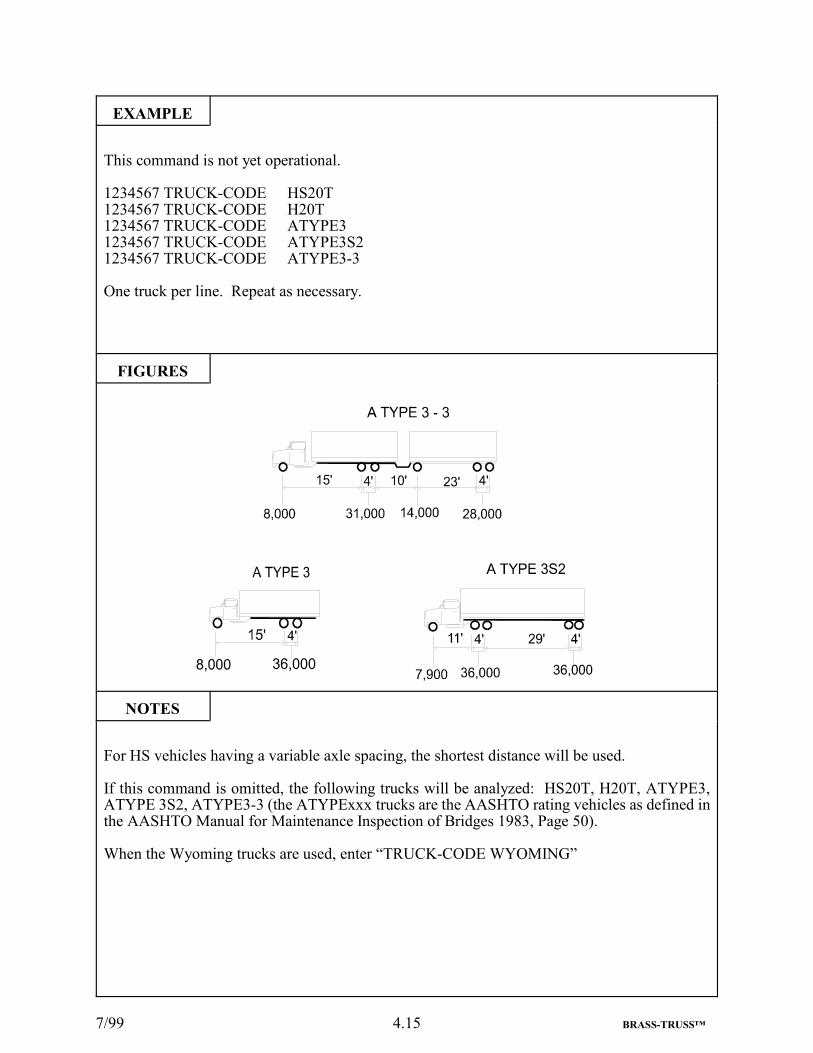
This command is not yet operational.
1234567 TRUCK-CODE HS20T1234567 TRUCK-CODE H20T1234567 TRUCK-CODE ATYPE31234567 TRUCK-CODE ATYPE3S21234567 TRUCK-CODE ATYPE3-3
One truck per line. Repeat as necessary.
FIGURES
NOTES
For HS vehicles having a variable axle spacing, the shortest distance will be used.
If this command is omitted, the following trucks will be analyzed: HS20T, H20T, ATYPE3,ATYPE 3S2, ATYPE3-3 (the ATYPExxx trucks are the AASHTO rating vehicles as defined inthe AASHTO Manual for Maintenance Inspection of Bridges 1983, Page 50).
When the Wyoming trucks are used, enter “TRUCK-CODE WYOMING”

7/99 4.16 BRASS-TRUSS™
70 BRASS-TRUSS™ COMMAND DESCRIPTION
COMMAND NAME STRESSES
PURPOSE This command is used to define the allowable yield strength ofthe members and fastener diameter. This command is required.
6 COMMAND PARAMETERS
Fy SteelDefault = See Notes
Enter the steel yield strength in ksi. If unknown or there are nostructural steel members in the bridge superstructure, enter 0and a default value based on the year of original constructionwill be used. For hybrid girders, enter the yield strength of theweb.
Fy Reinforcing Steel Enter the reinforcing steel yield strength in ksi. If unknown orthere is no reinforcing steel in the bridge superstructure, enter 0and a default value based on the year of original constructionwill be used.
Fpc ConcreteDefault = 3.3 ksi
Enter the concrete compressive strength in ksi. If unknown orthere is no concrete in the bridge superstructure, enter 0 and adefault value based on the year of original construction will beused.
Fy TimberDefault = 1.8 ksi
Enter the timber bending strength in ksi. If unknown or thereare no wood members in the bridge superstructure, enter 0 anda default value based on the year of original construction will beused.
This value will be multiplied by 0.55 for inventory stress leveland by 0.75 for operating stress level.
Reference material for these stresses are found in the followingspecifications:
A.A.S.H.T.O.A.I.S.C.A.S.T.M.
Fastener Diameter Enter the diameter of the fasteners used to fabricate theindividual member, in inches. This is NOT the fasteners usedin the connections. If this cannot be determined, enter 0 (Zero)and 7/8" diameter fasteners will be assumed. Diametersavailable are: 1.125, 1.000, 0.875, 0.750, 0.625, and 0.500 only.No other values are acceptable.
Hybrid Truss Fy Steel If there are two steel types used on a Truss, enter the higher steelyield strength, in ksi.

7/99 4.17 BRASS-TRUSS™
EXAMPLE
1234567 STRESSES 33.0 33.0 2.70 0. 0.875 33.0
FIGURES
NOTES
Steel Yield Strength Defaults (Fy)
YEAR Fy(ksi)<1900 23
1900 - 1904 261905 - 1935 301936 - 1962 331963 - (2050) 36

7/99 4.18 BRASS-TRUSS™
80 BRASS-TRUSS™ COMMAND DESCRIPTION
COMMAND NAME COMMENTS
PURPOSE
The COMMENTS command may be used to documentinformation concerning this bridge and to list information thatcannot be recorded on any other command. This command maybe repeated up to 999 times and may be placed anywhere in thedata set prior to the commands given in Chapter 10.
1 COMMAND PARAMETER
Comments Each comment may contain up to 60 characters of descriptivedata.

7/99 4.19 BRASS-TRUSS™
EXAMPLE
1234567 COMMENTS BR OVER LITTLE WIND RIVER
FIGURES
NOTES

7/99 4.20 BRASS-TRUSS™

7/99 5.1 BRASS-TRUSS™
5. CODING INSTRUCTIONS FOR ROADWAY DETAILS

7/99 5.2 BRASS-TRUSS™
90 BRASS-TRUSS™ COMMAND DESCRIPTION
COMMAND NAME WEARING SURFACE
PURPOSE This command is used to define the wearing surface thicknessand type. This command is required.
2 COMMAND PARAMETERS
Wearing Surface Thickness Enter the average distance, in inches, from the roadway to thetop of the structural deck. If the wearing surface thicknesscannot be determined, omit the entire command. See Figure.(Maximum = 12 inches, Minimum = 0 inches)
Wearing Surface Type Enter “CONCRETE”, “ASPHALT”, “TIMBER” or “NONE”.No other words are acceptable. If the deck is Open SteelGrating, enter “NONE”. If more than one type of overlaymaterial is used, enter only one type with an equivalentthickness to obtain the proper unit weight.

7/99 5.3 BRASS-TRUSS™
EXAMPLE
1234567 WEARING SURFACE 1.25 ASPHALT
FIGURES
NOTES
Wearing Surface Weight = Roadway Width x Wearing Surface Thickness x Unit Weight
MATERIAL UNIT WEIGHTConcrete 150 lbs. per cubic footTimber 50 lbs. per cubic footAsphalt 144 lbs. per cubic foot

7/99 5.4 BRASS-TRUSS™
100 BRASS-TRUSS™ COMMAND DESCRIPTION
COMMAND NAME PAVEMENT
PURPOSE This command defines the pavement width. This command isrequired.
2 COMMAND PARAMETERS
Left Pavement Width Enter the distance, in feet, between the curbs, or the face of therailings, parapets or other obstructions to the lateral movementof a vehicle on the bridge, on the left of the median. Use thisparameter for bridges without medians. See Figures.(Maximum = 75 feet, Minimum = 8 feet)
Right Pavement Width Enter the distance, in feet, between the curbs or the face of therailings, parapets or other obstructions to the lateral movementof a vehicle on the bridge, on the right of the median. If thereis no median on the bridge, enter 0 in this parameter. SeeFigures. (Maximum = 75 feet, Minimum = 0 feet)

7/99 5.5 BRASS-TRUSS™
EXAMPLE
1234567 PAVEMENT 24.0 0
FIGURES
NOTES
8/00 5.6 BRASS-TRUSS™
110 BRASS-TRUSS™ COMMAND DESCRIPTION
COMMAND NAME LEFT SIDEWALK
PURPOSE This command defines the left sidewalk and/or parapets on thedeck. This command is required.
6 COMMAND PARAMETERS
Left Sidewalk Width Enter the distance, in feet, from the curb line to the outside edgeof the left sidewalk if one is present. See Figures for alldimensions. (Maximum = 12 feet, Minimum = 0 feet)
Left Sidewalk Thickness Enter the sidewalk thickness in inches. (Maximum = 18 inches,Minimum = 0 inches)
Left Sidewalk or ParapetMaterial
Enter “STEEL”, “TIMBER”, “CONCRETE”, “GRATING”,“ASPHALT” or “NONE”. No other words are acceptable.
Left Sidewalk RailingMaterial
Enter “ALUMINUM”, “STEEL”, “TIMBER”, “CONCRETE”or “NONE”. No other words are acceptable.
Left Concrete Parapet Width Enter the average distance, in feet, from the inner face to theother face of the parapets. (Maximum = 2 feet, Minimum = 0feet)
Left Concrete Parapet Height Enter the distance, in feet, from the top of the deck or sidewalkto the top of the parapet. (Maximum = 4 feet, Minimum = 0feet)

8/00 5.7 BRASS-TRUSS™
EXAMPLE
1234567 LEFT SIDEWALK 0 0 NONE NONE 0 0
FIGURES
(Continued)

7/99 5.8 BRASS-TRUSS™
FIGURES(Cont.)
NOTES
Railing weights are based on the type of material input:
MATERIAL WEIGHTSteel 50 lbs. per linear footConcrete 200 lbs. per linear footTimber 20 lbs. per linear footAluminum 30 lbs. per linear foot

7/99 5.9 BRASS-TRUSS™

8/00 5.10 BRASS-TRUSS™
120 BRASS-TRUSS™ COMMAND DESCRIPTION
COMMAND NAME RIGHT SIDEWALK
PURPOSE This command defines the right sidewalk and/or parapets on thedeck. This command is required.
6 COMMAND PARAMETERS
Right Sidewalk Width Enter the distance, in feet, from the curb line to the outside edgeof the right sidewalk if one is present. See Figures for alldimensions. (Maximum = 12 feet, Minimum = 0 feet)
Right Sidewalk Thickness Enter the sidewalk thickness in inches. (Maximum = 18 inches,Minimum = 0 inches)
Right Sidewalk or ParapetMaterial
Enter “STEEL”, “TIMBER”, “CONCRETE”, “GRATING”,“ASPHALT” or “NONE”. No other words are acceptable.
Right Sidewalk RailingMaterial
Enter “ALUMINUM”, “STEEL”, “TIMBER”, “CONCRETE”or “NONE”. No other words are acceptable.
Right Concrete Parapet Width Enter the average distance, in feet, from the inner face to theother face of the parapets. (Maximum = 2 feet, Minimum = 0feet)
Right Concrete ParapetHeight
Enter the distance, in feet, from the top of the deck or sidewalkto the top of the parapet. (Maximum = 4 feet, Minimum = 0feet.

8/00 5.11 BRASS-TRUSS™
EXAMPLE
1234567 RIGHT SIDEWALK 0 0 NONE NONE 0 0
FIGURES
(Continued)

7/99 5.12 BRASS-TRUSS™
FIGURES(Cont.)
NOTES
Railing weights are based on the type of material input:
MATERIAL WEIGHTSteel 50 lbs. per linear footConcrete 200 lbs. per linear footTimber 20 lbs. per linear footAluminum 30 lbs. per linear foot

7/99 5.13 BRASS-TRUSS™

7/99 5.14 BRASS-TRUSS™
130 BRASS-TRUSS™ COMMAND DESCRIPTION
COMMAND NAME MEDIAN
PURPOSE This command defines the median and barrier on the deck. Thiscommand is optional.
4 COMMAND PARAMETERS
Median Width Enter the width of the median in feet. See Figures. (Maximum= 40 feet, Minimum = 0.2 feet)
Median Thickness Enter the distance, in inches, from the top of the median surfaceto the top of the roadway surface. (Maximum = 18 inches,Minimum = 0 inches)
Median Material Enter “CONCRETE”, “ASPHALT”, “STEEL”, “TIMBER” or“NONE”. No other words are acceptable.
Barrier Material Enter “CONCRETE”, “STEEL”, “TIMBER”, “ALUMINUM”or “NONE”. No other words are acceptable.

7/99 5.15 BRASS-TRUSS™
EXAMPLE
1234567 MEDIAN 10.0 9.0 CONCRETE STEEL
FIGURES
NOTES

7/99 5.16 BRASS-TRUSS™

7/99 6.1 BRASS-TRUSS™
6. CODING INSTRUCTIONS FOR RAILWAY AND UTILITIES DETAILS

7/99 6.2 BRASS-TRUSS™
140 BRASS-TRUSS™ COMMAND DESCRIPTION
COMMAND NAME MEMBER LAYOUT
PURPOSEThis command defines the locations of the main members. Thiscommand is optional. This command is required for railwaybridges only.
9 COMMAND PARAMETERS
Bridge Edge to Main Member Enter the distance, in feet, from the left edge of the bridge to thecenter line of the left main member. For thru-type structures,this dimension will probably be 0. For deck structures with tiesor some other type of track support, use the left edge of thissupport.
Main Member Spacing #1 Enter the distance, in feet, between the center lines of the mainmembers.
Main Member to Bridge Edgeor Main Member Spacing #2
Enter the distance*, in feet, from the center line of the last mainmember to the edge of the bridge or to the center line of the nextmain member.
Main Member to Bridge Edgeor Main Member Spacing #3
Enter the distance*, in feet, from the center line of the last mainmember to the edge of the bridge or to the center line of the nextmain member.
Main Member to Bridge Edgeor Main Member Spacing #4
Enter the distance*, in feet, from the center line of the last mainmember to the edge of the bridge or to the center line of the nextmain member.
Main Member to Bridge Edgeor Main Member Spacing #5
Enter the distance*, in feet, from the center line of the last mainmember to the edge of the bridge or to the center line of the nextmain member.
Main Member to Bridge Edgeor Main Member Spacing #6
Enter the distance*, in feet, from the center line of the last mainmember to the edge of the bridge or to the center line of the nextmain member.
Main Member to Bridge Edgeor Main Member Spacing #7
Enter the distance*, in feet, from the center line of the last mainmember to the edge of the bridge or to the center line of the nextmain member.
Main Member to Bridge Edgeor Main Member Spacing #8
Enter the distance*, in feet, from the center line of the last mainmember to the edge of the bridge or to the center line of the nextmain member.
*If this measurement is to the edge of the bridge, trailing zerosfor the remaining parameters are not required.

7/99 6.3 BRASS-TRUSS™
EXAMPLE
1234567 MEMBER LAYOUT 4.5 6.0 4.5
FIGURES
NOTES
7/99 6.4 BRASS-TRUSS™
150 BRASS-TRUSS™ COMMAND DESCRIPTION
COMMAND NAME RAILWAY
PURPOSEThis command defines the maximum permitted railway speed,the track radius, and track super elevation when tracks are onthe bridge. This command is optional.
3 COMMAND PARAMETERS
Track Speed Enter the maximum permitted speed for the section of trackwhen the track is in perfect condition (no “Slow Orders”).Speed is in Miles Per Hour.
Track Radius Enter the Center-of-track Radius, in feet, for any curved track onthe bridge. If the track alignment is straight, enter 0.
Super-Elevation Enter the difference in elevation, in inches, between the tops ofthe rails of the track whose radius has been entered in “TRACKRADIUS”.

7/99 6.5 BRASS-TRUSS™
EXAMPLE
1234567 RAILWAY 40 0 0
FIGURES
NOTES

7/99 6.6 BRASS-TRUSS™
160 BRASS-TRUSS™ COMMAND DESCRIPTION
COMMAND NAME TRACK LAYOUT
PURPOSE This command defines the position of a railway track on abridge. This command maybe repeated and is optional.
5 COMMAND PARAMETERS
Bridge Edge to Left RailTrack 1
Enter the distance, in feet, from the left edge of the bridge to theinside face of the top portion of the left rail* for each track. Forthru type of structures, use the center line of the truss or girderas the edge of the bridge. For deck structures with ties or someother type of track support, use the left edge of this support. Ifthere are less than 4 tracks, enter 0 where tracks do not exist.
Bridge Edge to Left RailTrack 2
Enter the distance, in feet, from the left edge of the bridge to theinside face of the top portion of the left rail* for each track. Forthru type of structures, use the center line of the truss or girderas the edge of the bridge. For deck structures with ties or someother type of track support, use the left edge of this support. Ifthere are less than 4 tracks, enter 0 where tracks do not exist.
Bridge Edge to Left RailTrack 3
Enter the distance, in feet, from the left edge of the bridge to theinside face of the top portion of the left rail* for each track. Forthru type of structures, use the center line of the truss or girderas the edge of the bridge. For deck structures with ties or someother type of track support, use the left edge of this support. Ifthere are less than 4 tracks, enter 0 where tracks do not exist.
Bridge Edge to Left RailTrack 4
Enter the distance, in feet, from the left edge of the bridge to theinside face of the top portion of the left rail* for each track. Forthru type of structures, use the center line of the truss or girderas the edge of the bridge. For deck structures with ties or someother type of track support, use the left edge of this support. Ifthere are less than 4 tracks, enter 0 where tracks do not exist.
Left Rail to Bridge Edge Enter the distance, in feet, from the inside face of the top portionof the left rail* of the last track to the edge of the bridge.
NOTE: If there is a middle main member, measure up to thatmember on the first “TRACK LAYOUT”. Start from themiddle main member and continue on the second “TRACKLAYOUT” command.
*This is commonly called the “Gage Line”.

7/99 6.7 BRASS-TRUSS™
EXAMPLE
1234567 TRACK LAYOUT 12.0 0 0 0 16.0
FIGURES
NOTES

7/99 6.8 BRASS-TRUSS™
170 BRASS-TRUSS™ COMMAND DESCRIPTION
COMMAND NAME UTILITIES
PURPOSEThis command is used to input utilities information. If theutilities are embedded in the sidewalk slab, do not enter themhere, note them in the COMMENTS. This command isoptional.
8 COMMAND PARAMETERS
Type Enter “CABLE”, “FLUID”, “GAS” or “UNKN” to identify thematerial carried in the conduits or pipes. No other words areacceptable. If there are more than one type, repeat thiscommand for each type.
Number Enter the number of each type of utility in a grouping.
Diameter Enter the diameter, in inches, of the individual conduit or pipeused to carry the utility on the bridge.
Material Enter the kind of conduit or pipe used. “ALUMINUM”,“STEEL”, and “OTHER” are the only acceptable words. Theword “STEEL” is to include cast iron and other similar weightmetals.
Weight Per Foot Enter the weight per foot, in pounds, of each type and/or size ofutility, if this value is known. If it is unknown, enter 0. Thisweight is for information only and is not used in computingsuperimposed dead loads. If the user wishes to include this deadload, increase the weight of the Wearing Surface.
Member Providing Supported Enter one of the names listed below to describe the structuralelement of the bridge that receives the weight of the utility first.Allowable names are: “FLOORBEAM”, “INTERIORSTRINGER”, “FASCIA STRINGER”, “LEFT TRUSS”,“RIGHT TRUSS”, “LEFT GIRDER”, “RIGHT GIRDER”,“INTERIOR GIRDER”, “FASCIA GIRDER” or “SLAB”.
Distance from Main Memberto be Rated to Location ofUtility
For a floorbeam, enter the distance, in feet, from the mainmember being rated to the location of the utility (see Figure 1).For an interior stringer or a fascia stringer enter the distance, infeet, from the stringer being rated to the location of the utility(see Figure 2). For all other types of main members being rated,enter 0 (see Figures 3 and 4).
Distance from Adjacent MainMember to Location of Utility
For a floorbeam, enter the distance, in feet, from the adjacentmain member to the location of the utility (see Figure 1). For aninterior stringer or a fascia stringer, enter the distance, in feet,from the adjacent stringer to the location of the utility (seeFigure 2). For all other types of adjacent members, enter 0 (seeFigures 3 and 4)

7/99 6.9 BRASS-TRUSS™
EXAMPLE
1234567 UTILITIES FLUID 1 6 STEEL 3.5 FLOORBEAM 1 21
FIGURES
NOTES
(Continued)

7/99 6.10 BRASS-TRUSS™
FIGURES(Cont.)
NOTES

7/99 7.1 BRASS-TRUSS™
7. CODING INSTRUCTIONS FOR DECK CROSS-SECTION AND SLEEPERS
7.1 GENERAL INFORMATION
Only one type of deck may be entered. If the “GRATING DECK” command is used, onlythe “STEEL SLEEPERS” command may be used. If the “TIMBER DECK” command isused, either “SLEEPERS” command may be used.

7/99 7.2 BRASS-TRUSS™
180 BRASS-TRUSS™ COMMAND DESCRIPTION
COMMAND NAME CONCRETE DECK
PURPOSE This command defines the concrete deck on a bridge. At leastone type of DECK command is required.
7 COMMAND PARAMETERS
Span Enter the center-to-center distance, in feet, between themembers supporting the deck. Enter 0 for reinforced concreteslab bridges. (Maximum = 30 feet, Minimum = 0 feet)
Depth Enter the distance, in inches, from the top of the structuralconcrete deck to the underside of a flat deck or to the crown ofa jack-arch deck. If there is a wearing surface thickness that isunknown, use the total thickness from the roadway to thebottom of the deck. For Stay in Place (SIP) forms, measure thedepth from the top of the SIP Forms. (See Figure 1) Range =24 inches to 5 inches and 0.
Type Enter “FLAT”, “ENCASED”, “SIP”, “NONE” or “JACK” inthis parameter. No other words are acceptable. A slab spanningbetween concrete members is considered “FLAT”. (See Figures2 and 3)
If an asphalt wearing surface over corrugated metal is used as adeck, use this command. The depth is taken from the top of theasphalt to the lower surface of the corrugated metal. The typeis “FLAT”, and note this on the COMMENTS command. For“BLAST”, “ENCASED”, or “JACK”, the CONCRETEPROTECTION command is to be used to determine the propersize of each profile.
NOTE: If 0 is entered in the Span or Depth parameter, enter 0in the 4 remaining parameters.
Number of Bottom Bars Enter the number of bottom bars per foot in the concrete deck.
Size of Bottom Bars Enter the size of the bottom bars used in the slab. (Range = #7to #3)
Number of Top Bars Enter the number of top bars per foot in the concrete deck.
Size of Top Bars Enter the size of the top bars used in the slab. (Range = #7 to#3)

7/99 7.3 BRASS-TRUSS™
EXAMPLE
1234567 CONCRETE DECK 4.5 9 FLAT 4 5 5 5
FIGURES
(Continued)

7/99 7.4 BRASS-TRUSS™
FIGURES(Cont)
NOTES

7/99 7.5 BRASS-TRUSS™

7/99 7.6 BRASS-TRUSS™
190 BRASS-TRUSS™ COMMAND DESCRIPTION
COMMAND NAME GRATING DECK
PURPOSE This command defines the grating deck on a bridge. At leastone type of DECK command is required.
5 COMMAND PARAMETERS
Span Enter the center-to-center distance, in feet, of the memberssupporting the deck. (Maximum = 9 feet, Minimum = 1 foot)
Main Bar Depth Enter the depth, in inches, of the deepest grating bars that arebeing supported on the next level below the grating whosecenter-to-center distance was entered above. (See Figures) (Maximum = 9 inches, Minimum = 2 inches)
Main Bar Thickness Enter the thickness, in inches, of the main bars. (Maximum =1 inch, Minimum = 0.1 inch)
Main Bar Spacing Enter the center-to-center distance, in inches, of the main bars.(Maximum = 15 inches, Minimum = 2 inches)
Type Enter the type of grating construction; either “FILLED” or“OPEN”. No other words are acceptable.

7/99 7.7 BRASS-TRUSS™
EXAMPLE
1234567 GRATING DECK 4.5 8 .5 9 OPEN
FIGURES
NOTES

7/99 7.8 BRASS-TRUSS™
200 BRASS-TRUSS™ COMMAND DESCRIPTION
COMMAND NAME TIMBER DECK
PURPOSE This command defines the timber deck on a bridge. At least onetype of DECK command is required.
4 COMMAND PARAMETERS
Span Enter the center-to-center distance, in feet, of the memberssupporting the deck. (Maximum = 9 feet, Minimum = 1 foot)
NOTE: When there is no timber deck on top of timber girders,enter 0 in all of the remaining fields and note on the“COMMENTS” command.
Depth Enter the depth, in inches, of the timbers that are used as deckmembers. (See Figures) (Maximum = 18 inches, Minimum =2 inches)
Width Enter the width, in inches, of the timbers. (Maximum = 12inches, Minimum = 0.75 inches)
Stress Grade If the stress grade, in ksi, was not zero on the “STRESSES”command, and/or the stress grade for the timber deck isdifferent than the one given on the “STRESSES” command,enter it here. If the two values are equal or the value for thetimber deck is unknown, enter 0.

7/99 7.9 BRASS-TRUSS™
EXAMPLE
1234567 TIMBER DECK 5.5 8.5 5.5 0
FIGURES
NOTES

8/00 7.10 BRASS-TRUSS™
210 BRASS-TRUSS™ COMMAND DESCRIPTION
COMMAND NAME STEEL SLEEPERS
PURPOSE This command defines the steel sleepers on a bridge. Thiscommand is optional.
4 COMMAND PARAMETERS
Span Enter the center-to-center distance, in feet, between themembers supporting the sleepers. (See Figure) (Maximum =9 feet, Minimum = 1 foot) For deterioration of the section,enter the word “RUST”. See Note 1.
Depth Enter the depth, in inches, of the members that are used as thesleepers. See Note 2. (Maximum = 12 inches, Minimum = 2inches)
Flange Widthor“W” + Weight per Foot
Enter the width, in inches, of the flange(s). If a channel orrolled beam section is specified on the “As Built” plans, enterthe letter “W” followed by the weight per foot from these plans.See Note 2. (Maximum = 11.5 inches, Minimum = 1.5 inches)
Flange Thickness Enter the average thickness, in inches, of the flange(s). If theweight per foot was entered above, enter 0. (Range = 1 inch to.15 inch and 0)

7.11
EXAMPLE
1234567 STEEL SLEEPERS 4.5 10 3.033 0.436 (Channel)
1234567 STEEL SLEEPERS 4.5 18 W55 0 (WN18x55 - First 18x55 section listed)
1234567 STEEL SLEEPERS 4.5 18 6.000 0.691 (W18x55 - Second 18x55 section listed)
FIGURES
NOTES
1. If there is any deterioration of any sleepers, enter one command fully as normal. Then repeat thiscommand and enter the word “RUST” in the first parameter. For the remainder of the second commandenter the percentage of area loss for a particular element, or the percentage of dimension loss for theappropriate element. See Chapter 13 for a detailed explanation of the information required fordeterioration.
2. There are two ways the user can select a sleeper from the sections library. 1) The user may input asection depth and flange width in Parameters 2 and 3. The program will search the library for the firstoccurance of this combination of values. If a section is not found in the library, the program tries to finda section within c” of the dimensions input. If a section is not found, an error message appears in theoutput. 2) If a W Section or Channel is specified on the “As Built” plans, the user may input a one or twodigit integer section depth corresponding to the beam depth as listed under “Designation” in the AISCManual of Steel Construction in Parameter 2 and input the letter “W” followed by the weight per foot inParameter 3. The program will search the library for the first occurance of the combination of depth andweight. Note: The use of the letter “W” does not restrict the user to W sections in the AISC Manual ofSteel Construction. The letter “W” is merely a flag to tell the program to search for a rolled section (Wsection, channel, or angle). If a section is not found, an error message appears in the output. Note: In thestandard sections library, some standard shapes begin with “W” and “WN” (i.e., W24X76 andWN24X76). In 1985, AISC changed the dimensions of several steel shapes while keeping the samedesignation. To differentiate between the two types (especially when the older shape is needed to performa rating) an “N” was added to the shape designation to indicate a NEW shape. In the event the user wishesto select the second occurance of a section listed in the library, use the first method described above andinput the specific flange width as it appears in the library. See the example above. Note: A zero mustbe entered in Parameter 4 when an AISC shape is entered in Parameters 2 and 3.
The shape you enter must exist in the standard shapes library, stsect.dat. This library is a binary fileand is not easily readable. An ASCII copy of this file has been placed on the FTP Server for viewing.

7/99 7.12 BRASS-TRUSS™
220 BRASS-TRUSS™ COMMAND DESCRIPTION
COMMAND NAME TIMBER SLEEPERS
PURPOSE This command defines the timber sleepers on a bridge. Thiscommand is optional.
4 COMMAND PARAMETERS
Span Enter the center-to-center distance, in feet, between themembers supporting the sleepers. (See Figure) (Maximum = 9feet, Minimum = 1 foot) For deterioration of the section, enterthe word “ROT”. (See Notes)
Depth Enter the depth, in inches, of the timbers that are used as thesleepers. (Maximum = 18 inches, Minimum = 4 inches)
Width Enter the width, in inches, of the timbers. (Maximum = 12inches, Minimum = 2 inches)
Stress If the stress grade was not 0 on the “STRESSES” command,and/or the stress grade for the timber sleepers is different thanthe one given on the “STRESSES” command, enter it here, inksi. If the two values are equal or the value for the timbersleepers is unknown, enter 0.

7/99 7.13 BRASS-TRUSS™
EXAMPLE
1234567 TIMBER SLEEPERS 4.5 8 5.5 0
FIGURES
NOTES
If there is any deterioration of any sleepers, enter one command fully as normal. Then repeat thiscommand and enter the word “ROT” in the first parameter. For the remainder of the secondcommand enter the percentage of area loss for a particular element, or the percentage of dimensionloss for the appropriate element. See Chapter 13 for a detailed explanation of the informationrequired for deterioration.

7/99 7.14 BRASS-TRUSS™

7/99 8.1 BRASS-TRUSS™
8. CODING INSTRUCTIONS FOR SECONDARY MEMBERS - STRINGERS

7/99 8.2 BRASS-TRUSS™
230 BRASS-TRUSS™ COMMAND DESCRIPTION
COMMAND NAME SECONDARY MEMBER LONGITUDINAL STRINGER
PURPOSEThis command defines the secondary member - longitudinalstringers on the bridge. This command is required whenstringers are present.
5 COMMAND PARAMETERS
Span Enter the center-to-center distance, in feet, of the memberssupporting the stringers. (Maximum = 50 feet, Minimum = 3feet)
Number of Continuous Spans Enter the number of spans through which the stringers are actingcontinuously. Enter 0 for a simple span. (Maximum = 8 spans,Minimum = 0 spans, 1 is not acceptable)
Haunch Depth Enter the average distance, in inches, from the top of the stringerflange to the bottom of the concrete deck. If the top of thestringer top flange is at or above the bottom of the slab, enter 0.If non-composite, enter 0. See Figure 1. (Maximum = 6 inches,Minimum = 0 inches)
Number of Stringers Enter the number of stringers that support the roadway.
Compression Flange Restraint Enter “YES” or “NO”, “Y” or “N”. Nothing else is acceptable.Use “YES” or “Y” if any of the following conditions exists:
1) The presence of shear connectors.
2) The stringers are encased, have blast protection, or areenclosed by jack arch construction. See Figure 2.
3) The concrete deck extends down to the bottom of thetop flange (zero haunch, see Figure 1).
4) The sleepers or the steel grating is adequately attachedto the top flange.
Use “NO” or “N” for ALL other conditions.

7/99 8.3 BRASS-TRUSS™
EXAMPLE
1234567 SECONDARY MEMBER LONGITUDINAL STRINGER 20 0 0 5 YES
FIGURES
NOTES

8/00 8.4 BRASS-TRUSS™
240 BRASS-TRUSS™ COMMAND DESCRIPTION
COMMAND NAME LEFT SIDEWALK STRINGER
PURPOSE This command defines the left sidewalk stringer on a bridge.This command is optional.
5 COMMAND PARAMETERS
Type of Supporting Members Enter “TIMBER”, “CHANNEL” or “ROLLED” to describe thekind of members supporting the left sidewalk. No other wordsare acceptable. See Figures.
Member Depth Enter the depth, in inches, of the left sidewalk stringer. SeeNotes. (Maximum = 37 inches, Minimum = 3 inches)
Member Flange Widthor“W” + Weight per Foot
Enter the flange width, in inches. If a channel or rolled beamsection is specified on the “As Built” plans, enter the letter “W”followed by the weight per foot from these plans. See Notes.Enter the width, in inches, of timber members. (Maximum = 17inches, Minimum = 1.5 inches)
Member Flange Thickness Enter the average flange thickness, in inches. If the weight perfoot was entered above, or the type of supporting members istimber, enter 0. (Maximum = 1.7 inches, Minimum = 0 inches)
Number of Members Enter the number of stringers supporting the left sidewalk.
NOTE: For special loads in the sidewalk area (trusses left inplace that are carried by new thru or deck girders, heavy utilityvaults, etc.), on bridge types that allow the use of stringers, enter“ROLLED” in the Type of Supporting Member parameter.Enter “99" in the Member Depth parameters. Enter “W” and theweight per foot needed to account for the actual sidewalkstringers, if present, plus the special load in the Member FlangeWidth parameter. Enter “0" in the Member Flange Thicknessparameter. Enter “1" in the Number of Members parameter.Note the actual conditions in the Comments.

8/00 8.5 BRASS-TRUSS™
EXAMPLE
1234567 LEFT SIDEWALK STRINGER ROLLED 18 W55 0 3 (WN 18x55 - First 18x55 section listed in sections library)
1234567 LEFT SIDEWALK STRINGER ROLLED 18 6.000 0.691 3 (W 18x55 - Second 18x55 section listed in sections library)
1234567 LEFT SIDEWALK STRINGER CHANNEL 9 W20 0 2
FIGURES

8/00 8.6 BRASS-TRUSS™
NOTES
There are two ways the user can select a stringer from the sections library. 1) The user may input asection depth and flange width in Parameters 2 and 3. The program will search the library for the firstoccurrence of this combination of values. If a section is not found in the library, the program tries tofind a section within c” of the dimensions input. If a section is not found, an error message appearsin the output. 2) If a W Section or Channel is specified on the “As Built” plans, the user may input aone or two digit integer section depth corresponding to the beam depth as listed under “Designation”in the AISC Manual of Steel Construction in Parameter 2 and input the letter “W” followed by theweight per foot in Parameter 3. The program will search the library for the first occurrence of thecombination of depth and weight. Note: The use of the letter “W” does not restrict the user to Wsections in the AISC Manual of Steel Construction. The letter “W” is merely a flag to tell theprogram to search for a rolled section (W section, channel, or angle). If a section is not found, an errormessage appears in the output. Note: In the standard sections library, some standard shapes beginwith “W” and “WN” (i.e., W24X76 and WN24X76). In 1985, AISC changed the dimensions ofseveral steel shapes while keeping the same designation. To differentiate between the two types(especially when the older shape is needed to perform a rating) an “N” was added to the shapedesignation to indicate a NEW shape. In the event the user wishes to select the second occurrence ofa section listed in the library, use the first method described above and input the specific flange widthas it appears in the library. See the example above. Note: A zero must be entered in Parameter 4when an AISC shape is entered in Parameters 2 and 3.
The shape you enter must exist in the standard shapes library, stsect.dat. This library is a binaryfile and is not easily readable. An ASCII copy of this file has been placed on the FTP Server forviewing.

8/00 8.7 BRASS-TRUSS™

8/00 8.8 BRASS-TRUSS™
250 BRASS-TRUSS™ COMMAND DESCRIPTION
COMMAND NAME RIGHT SIDEWALK STRINGER
PURPOSE This command defines the right sidewalk stringer on a bridge.This command is optional.
5 COMMAND PARAMETERS
Type of Supporting Members Enter “TIMBER”, “CHANNEL” or “ROLLED” to describe thekind of members supporting the right sidewalk. No other wordsare acceptable. See Figures.
Member Depth Enter the depth, in inches, of the right sidewalk stringer. SeeNotes. (Maximum = 37 inches, Minimum = 3 inches)
Member Flange Widthor“W” + Weight per Foot
Enter the flange width, in inches. If a channel or rolled beamsection is specified on the “As Built” plans, enter the letter “W”followed by the weight per foot from these plans. See Notes.Enter the width, in inches, of timber members. (Maximum = 17inches, Minimum = 1.5 inches)
Member Flange Thickness Enter the average flange thickness, in inches. If the weight perfoot was entered above, or the type of supporting members istimber, enter 0. (Maximum = 1.7 inches, Minimum = 0 inches)
Number of Members Enter the number of stringers supporting the right sidewalk.
NOTE: For special loads in the sidewalk area (trusses left inplace that are carried by new thru or deck girders, heavy utilityvaults, etc.), on bridge types that allow the use of stringers, enter“ROLLED” in the Type of Supporting Member parameter.Enter “99" in the Member Depth parameters. Enter “W” and theweight per foot needed to account for the actual sidewalkstringers, if present, plus the special load in the Member FlangeWidth parameter. Enter “0" in the Member Flange Thicknessparameter. Enter “1" in the Number of Members parameter.Note the actual conditions in the Comments.

8/00 8.9 BRASS-TRUSS™
EXAMPLE
1234567 RIGHT SIDEWALK STRINGER ROLLED 18 W55 0 3 (WN 18x55 - First 18x55 section listed in sections library)
1234567 RIGHT SIDEWALK STRINGER ROLLED 18 6.000 0.691 3 (W 18x55 - Second 18x55 section listed in sections library)
1234567 RIGHT SIDEWALK STRINGER CHANNEL 9 W20 0 2
FIGURES
Right Sidewalk

8/00 8.10 BRASS-TRUSS™
NOTES
There are two ways the user can select a stringer from the sections library. 1) The user may input asection depth and flange width in Parameters 2 and 3. The program will search the library for the firstoccurrence of this combination of values. If a section is not found in the library, the program tries tofind a section within c” of the dimensions input. If a section is not found, an error message appearsin the output. 2) If a W Section or Channel is specified on the “As Built” plans, the user may input aone or two digit integer section depth corresponding to the beam depth as listed under “Designation”in the AISC Manual of Steel Construction in Parameter 2 and input the letter “W” followed by theweight per foot in Parameter 3. The program will search the library for the first occurrence of thecombination of depth and weight. Note: The use of the letter “W” does not restrict the user to Wsections in the AISC Manual of Steel Construction. The letter “W” is merely a flag to tell theprogram to search for a rolled section (W section, channel, or angle). If a section is not found, an errormessage appears in the output. Note: In the standard sections library, some standard shapes beginwith “W” and “WN” (i.e., W24X76 and WN24X76). In 1985, AISC changed the dimensions ofseveral steel shapes while keeping the same designation. To differentiate between the two types(especially when the older shape is needed to perform a rating) an “N” was added to the shapedesignation to indicate a NEW shape. In the event the user wishes to select the second occurrence ofa section listed in the library, use the first method described above and input the specific flange widthas it appears in the library. See the example above. Note: A zero must be entered in Parameter 4when an AISC shape is entered in Parameters 2 and 3.
The shape you enter must exist in the standard shapes library, stsect.dat. This library is a binaryfile and is not easily readable. An ASCII copy of this file has been placed on the FTP Server forviewing.

8/00 8.11 BRASS-TRUSS™

8/00 8.12 BRASS-TRUSS™
260 BRASS-TRUSS™ COMMAND DESCRIPTION
COMMAND NAME CONCRETE PROTECTION LONGITUDINALSTRINGER
PURPOSEThis command defines the concrete protection on a longitudinalstringer. This command is optional.
2 COMMAND PARAMETERS
Flange Depth If “BLAST” is entered in the Type parameter on theCONCRETE DECK command, enter the distance, in inches,from the bottom of the concrete to the top of the concrete that iscovering the bottom flange. If “ENCASED” is entered in theType parameter on the CONCRETE DECK command, enter thedistance, in inches, from the bottom of the concrete slab to thebottom of the concrete that is covering the bottom flange. SeeFigures.
Web Thickness If “BLAST” is entered in the Type parameter on theCONCRETE DECK command, enter the distance, in inches,from one side of the concrete covering the web to the otherabove the bottom flange. If “ENCASED” is entered in the Typeparameter on the CONCRETE DECK command, enter thedistance, in inches, from one side of the concrete to the other.See Figures.

8/00 8.13 BRASS-TRUSS™
EXAMPLE
1234567 CONCRETE PROTECTION LONGITUDINAL STRINGER 12 2
FIGURES
NOTES
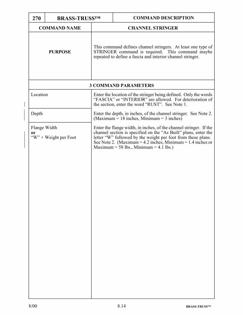
8/00 8.14 BRASS-TRUSS™
270 BRASS-TRUSS™ COMMAND DESCRIPTION
COMMAND NAME CHANNEL STRINGER
PURPOSEThis command defines channel stringers. At least one type ofSTRINGER command is required. This command mayberepeated to define a fascia and interior channel stringer.
3 COMMAND PARAMETERS
Location Enter the location of the stringer being defined. Only the words“FASCIA” or “INTERIOR” are allowed. For deterioration ofthe section, enter the word “RUST”. See Note 1.
Depth Enter the depth, in inches, of the channel stringer. See Note 2.(Maximum = 18 inches, Minimum = 3 inches)
Flange Widthor“W” + Weight per Foot
Enter the flange width, in inches, of the channel stringer. If thechannel section is specified on the “As Built” plans, enter theletter “W” followed by the weight per foot from these plans. See Note 2. (Maximum = 4.2 inches, Minimum = 1.4 inches orMaximum = 58 lbs., Minimum = 4.1 lbs.)
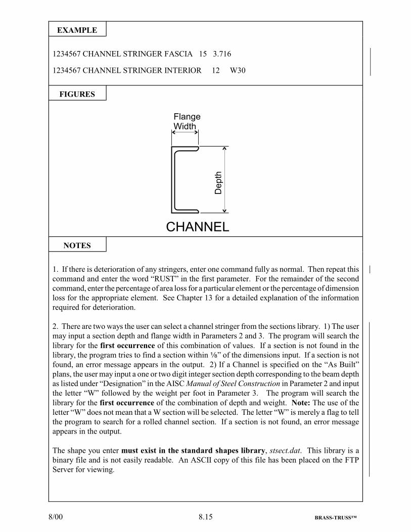
8/00 8.15 BRASS-TRUSS™
EXAMPLE
1234567 CHANNEL STRINGER FASCIA 15 3.716
1234567 CHANNEL STRINGER INTERIOR 12 W30
FIGURES
NOTES
1. If there is deterioration of any stringers, enter one command fully as normal. Then repeat thiscommand and enter the word “RUST” in the first parameter. For the remainder of the secondcommand, enter the percentage of area loss for a particular element or the percentage of dimensionloss for the appropriate element. See Chapter 13 for a detailed explanation of the informationrequired for deterioration.
2. There are two ways the user can select a channel stringer from the sections library. 1) The usermay input a section depth and flange width in Parameters 2 and 3. The program will search thelibrary for the first occurrence of this combination of values. If a section is not found in thelibrary, the program tries to find a section within c” of the dimensions input. If a section is notfound, an error message appears in the output. 2) If a Channel is specified on the “As Built”plans, the user may input a one or two digit integer section depth corresponding to the beam depthas listed under “Designation” in the AISC Manual of Steel Construction in Parameter 2 and inputthe letter “W” followed by the weight per foot in Parameter 3. The program will search thelibrary for the first occurrence of the combination of depth and weight. Note: The use of theletter “W” does not mean that a W section will be selected. The letter “W” is merely a flag to tellthe program to search for a rolled channel section. If a section is not found, an error messageappears in the output.
The shape you enter must exist in the standard shapes library, stsect.dat. This library is abinary file and is not easily readable. An ASCII copy of this file has been placed on the FTPServer for viewing.

8/00 8.16 BRASS-TRUSS™
280 BRASS-TRUSS™ COMMAND DESCRIPTION
COMMAND NAME ROLLED STRINGER
PURPOSEThis command defines rolled stringers. At least one type ofSTRINGER command is required. This command may berepeated to define a fascia and interior rolled beam stringer.
4 COMMAND PARAMETERS
Location Enter the location of the stringer being defined. Only the words“FASCIA” or “INTERIOR” are allowed. For deterioration ofthe section, enter the word “RUST”. See Note 1.
Depth Enter the depth, in inches, of the rolled beam stringer. See Note2. (Maximum = 37 inches, Minimum = 3 inches)
Flange Widthor“W” + Weight per Foot
Enter the flange width, in inches, of the rolled beam stringer. Ifthe rolled beam section is specified on the “As Built” plans,enter the letter “W” followed by the weight per foot from theseplans. See Note 2. (Maximum = 18 inches, Minimum = 2inches or Maximum = 730 lbs., Minimum = 5.1 lbs.)
Flange Thickness Enter the average flange thickness, in inches, of the rolled beamstringer. If the weight per foot was entered in Flange Width,enter 0. (Maximum = 5 inches, Minimum = 0.18 inches or 0inches)

8/00 8.17 BRASS-TRUSS™
EXAMPLE
1234567 ROLLED STRINGER INTERIOR 21 8.355 0.835
1234567 ROLLED STRINGER FASCIA 24 W104 0 (WN 24x104 - First 24x104 section listed in sections library)
1234567 ROLLED STRINGER FASCIA 24 9.775 0.942 (W 24x104 - Second 24x104 section listed in sections library)
FIGURES
NOTES
1. If there is deterioration of any stringers, enter one command fully as normal. Then repeat thiscommand and enter the word “RUST” in the first parameter. For the remainder of the secondcommand, enter the percentage of area loss for a particular element, or the percentage ofdimension loss for the appropriate element. See Chapter 13 for a detailed explanation of theinformation required for deterioration.
2. There are two ways the user can select a rolled stringer from the sections library. 1) The usermay input a section depth and flange width in Parameters 2 and 3. The program will search thelibrary for the first occurrence of this combination of values. If a section is not found in thelibrary, the program tries to find a section within c” of the dimensions input. If a section is notfound, an error message appears in the output. 2) If a W section is specified on the “As Built”plans, the user may input a one or two digit integer section depth corresponding to the beam depthas listed under “Designation” in the AISC Manual of Steel Construction in Parameter 2 and inputthe letter “W” followed by the weight per foot in Parameter 3. The program will search thelibrary for the first occurrence of the combination of depth and weight. If a section is not found,an error message appears in the output. Note: In the standard sections library, some standardshapes begin with “W” and “WN” (i.e., W24X76 and WN24X76). In 1985, AISC changed thedimensions of several steel shapes while keeping the same designation. To differentiate betweenthe two types (especially when the older shape is needed to perform a rating) an “N” was addedto the shape designation to indicate a NEW shape. In the event the user wishes to select thesecond occurrence of a section listed in the library, use the first method described above andinput the specific flange width as it appears in the library. See the example above. Note: A zeromust be entered in Parameter 4 when an AISC shape is entered in Parameters 2 and 3.
The shape you enter must exist in the standard shapes library, stsect.dat. This library is abinary file and is not easily readable. An ASCII copy of this file has been placed on the FTPServer for viewing.

8/00 8.18 BRASS-TRUSS™
290 BRASS-TRUSS™ COMMAND DESCRIPTION
COMMAND NAME TIMBER STRINGER
PURPOSEThis command defines timber stringers. At least one type ofSTRINGER command is required. This command may berepeated to define a fascia and interior timber stringer.
4 COMMAND PARAMETERS
Location Enter the location of the stringer being defined. Only the words“FASCIA” or “INTERIOR” are allowed. For deterioration ofthe section, enter the word “ROT” (See Notes).
Depth Enter the depth, in inches, of the timber stringer. (Maximum =18 inches, Minimum = 6 inches)
Width Enter the width, in inches, of the timber stringer. (Maximum = 12 inches, Minimum = 2 inches)
Stress Grade If the stress grade was not 0 on the STRESSES command,and/or the stress grade for the timber stringers is different thanthe one given on the STRESSES command, enter it here, in ksi.If the two values are equal or the value for the timber stringersis unknown, enter 0.

8/00 8.19 BRASS-TRUSS™
EXAMPLE
1234567 TIMBER STRINGER FASCIA 18 9 01234567 TIMBER STRINGER ROT
FIGURES
NOTES
If there is a deterioration of any stringers, enter one command fully as normal. Then repeat thiscommand and enter the word “ROT” in the first parameter. For the remainder of the secondcommand enter the percentage of area loss for a particular element, or the percentage of dimensionloss for the appropriate element. See Chapter 13 for a detailed explanation of the informationrequired for deterioration.

8/00 8.20 BRASS-TRUSS™

7/99 9.1 BRASS-TRUSS™
9. CODING INSTRUCTIONS FOR SECONDARY MEMBERS - FLOORBEAMS
9.1 GENERAL INFORMATION
If a “TIMBER” floorbeam is encountered, enter it as an equal weight steel “ISEC” with only a“WEB PLATE” of equal depth. Note the actual size of the COMMENTS command.

8/00 9.2 BRASS-TRUSS™
300 BRASS-TRUSS™ COMMAND DESCRIPTION
COMMAND NAME SECONDARY MEMBER TRANSVERSEFLOORBEAM
PURPOSE This command defines the secondary member transverse floorbeams. This command is required.
6 COMMAND PARAMETERS
Span Enter the center-to-center distance, in feet, of the memberssupporting the floorbeams. (Maximum = 60 feet, Minimum =8 feet) See Figure 1.
Left Floorbeam CantileverLength
Enter the distance, in feet, from the center of the membersupporting the floorbeam to the outer extremity of thefloorbeam for “DECK” Type Bridges. For “TRUSSES” withinverted “U”-bolt hanger connections, enter the sidewalk widthfrom the curb line to the end of the floorbeam and the floorbeamcantilever dimension from the hanger to the end of thefloorbeam. (Maximum = 35 feet, Minimum = 0 feet)
Right Floorbeam CantileverLength
Enter the distance, in feet, from the center of the membersupporting the floorbeam to the outer extremity of thefloorbeam for “DECK” Type Bridges. For “TRUSSES” withinverted “U”-bolt hanger connections, enter the sidewalk widthfrom the curb line to the end of the floorbeam and the floorbeamcantilever dimension from the hanger to the end of thefloorbeam. (Maximum = 35 feet, Minimum = 0 feet)
Haunch Depth If the space between the bottom of the concrete deck and the topof the floorbeam flange is filled with concrete, enter thisdistance, in inches. If the bottom of the concrete deck is flushwith the top of the floorbeam flange or this space is not filledwith concrete, enter 0. If non-composite, enter 0. See Figure 2.(Maximum = 9 inches, Minimum = 0 inches)
Floorbeam Skew Angle Enter the angle, in degrees, between the centerline of thefloorbeam and a line perpendicular to the roadway centerline.(Maximum 75°, Minimum 0°)
Compression Flange Restraint Enter “YES” or “NO”, “Y” or “N”. Nothing else is acceptable.Use “YES” or “Y” if any of the following conditions exist:1) The presence of shear connectors.2) The floorbeams are encased, have blast protection or are
enclosed by jack arch construction.3) The concrete deck extends down to the bottom of the
top flange.4) The grating is adequately attached to the top flange.5) The stringers are framed into or the top flange is seated
on the floorbeam at 5.0' or less.Use “NO” or “N” for ALL other conditions.

8/00 9.3 BRASS-TRUSS™
EXAMPLE
1234567 SECONDARY MEMBER TRANSVERSE FLOORBEAM 24 0 0 0 0 N
FIGURES
NOTES
Floorbeams are analyzed as Non-Composite.

7/99 9.4 BRASS-TRUSS™
310 BRASS-TRUSS™ COMMAND DESCRIPTION
COMMAND NAME CONCRETE PROTECTION TRANSVERSEFLOORBEAM
PURPOSE This command defines the concrete protection on the secondarymember transverse floorbeam. This command is optional.
2 COMMAND PARAMETERS
Flange Thickness If “BLAST” is entered in the Type parameter on theCONCRETE DECK command, enter the distance, in inches,from the bottom of the concrete to the top of the concrete that iscovering the bottom flange. See Figures.
Web Thickness If “BLAST” is entered in the Type parameter on theCONCRETE DECK command, enter the distance, in inches,from one side of the concrete covering the web to the otherabove the bottom flange. See Figures.

7/99 9.5 BRASS-TRUSS™
EXAMPLE
1234567 CONCRETE PROTECTION TRANSVERSE FLOORBEAM 4 4
FIGURES
NOTES

8/00 9.6 BRASS-TRUSS™
320 BRASS-TRUSS™ COMMAND DESCRIPTION
COMMAND NAME CHANNEL FLOORBEAM
PURPOSEThis command defines channel floorbeams. At least one typeof FLOORBEAM command is required. This command may berepeated to define an end and intermediate floorbeam.
3 COMMAND PARAMETERS
Location Enter the location of the floorbeam being defined. Only thewords “END” or “INTERMEDIATE” are allowed. Fordeterioration of the section, enter the word “RUST”. See Note1.
Depth Enter the depth, in inches, of the channel floorbeam. See Note3. (Maximum = 18 inches, Minimum = 3 inches)
Flange Widthor“W” + Weight per Foot
Enter the flange width, in inches, of the channel floorbeam. Ifthe channel section is specified on the “As Built” plans, enterthe letter “W” followed by the weight per foot from these plans.See Note 2. and 3. (Maximum = 4.2 inches, Minimum = 1.4inches, or Maximum = 58 lbs., Minimum = 4.1 lbs.)

8/00 9.7 BRASS-TRUSS™
EXAMPLE
1234567 CHANNEL FLOORBEAM END 15 3.716
1234567 CHANNEL FLOORBEAM INTERMEDIATE 12 W30
FIGURES
NOTES
1. If there is deterioration of the floorbeams, enter one command fully as normal. Then repeat thiscommand and enter the word “RUST” in the first parameter. For the remainder of the secondcommand, enter the percentage of area loss for a particular element, or the percentage of dimensionloss for the appropriate element. See Chapter 13 for a detailed explanation of the informationrequired for deterioration.
2. Cover plates may not be used with a channel floorbeam. If cover plates exist, convert the sectionto an equivalent I-Section.
3. There are two ways the user can select a channel floorbeam from the sections library. 1) The usermay input a section depth and flange width in Parameters 2 and 3. The program will search the
library for the first occurrence of this combination of values. If a section is not found in the library,the program tries to find a section within c” of the dimensions input. If a section is not found, anerror message appears in the output. 2) If a Channel is specified on the “As Built” plans, the user mayinput a one or two digit integer section depth corresponding to the beam depth as listed under“Designation” in the AISC Manual of Steel Construction in Parameter 2 and input the letter “W”
followed by the weight per foot in Parameter 3. The program will search the library for the first
occurrence of the combination of depth and weight. Note: The use of the letter “W” does not meanthat a W section will be selected. The letter “W” is merely a flag to tell the program to search for arolled channel section. If a section is not found, an error message appears in the output.
The shape you enter must exist in the standard shapes library, stsect.dat. This library is a binaryfile and is not easily readable. An ASCII copy of this file has been placed on the FTP Server forviewing.

8/00 9.8 BRASS-TRUSS™
330 BRASS-TRUSS™ COMMAND DESCRIPTION
COMMAND NAME ROLLED FLOORBEAM
PURPOSEThis command defines rolled beam floorbeams. At least onetype of FLOORBEAM command is required. This commandmay be repeated to define an end and intermediate floorbeam.
8 COMMAND PARAMETERS
Location Enter the location of the floorbeam being defined. Only thewords “END” or “INTERMEDIATE” are allowed. Fordeterioration of the section, enter the word “RUST”. See Note1
Depth Enter the depth, in inches, of the rolled beam floorbeam. SeeNote 2. (Maximum = 37 inches, Minimum = 3 inches)
Flange Widthor“W” + Weight per Foot
Enter the flange width, in inches, of the rolled beam floorbeam.If the rolled beam section is specified on the “As Built” plans,enter the letter “W” followed by the weight per foot from theseplans. See Note 2. (Maximum = 18 inches, Minimum = 2inches or Maximum = 730 lbs., Minimum = 5.1 lbs.)
Flange Thickness Enter the average flange thickness, in inches, of the rolled beamfloorbeam. If the weight per foot was entered in Flange Width,enter 0. (Range = 5 inches to 0.18 inches and 0)
Top CoverPlate Width
Enter the width of the top cover plate, in inches.
Top CoverPlate Thickness
Enter the thickness of the top cover plate, in inches.
Bottom CoverPlate Width
Enter the width of the bottom cover plate, in inches.
Bottom CoverPlate Thickness
Enter the thickness of the bottom cover plate, in inches.

8/00 9.9 BRASS-TRUSS™
EXAMPLE
1234567 ROLLED FLOORBEAM END 21 8.355 0.835 0 0 0
1234567 ROLLED FLOORBEAM INTERMEDIATE 24 W104 0 0 0 0 (WN 24x104 - First 24x104 section listed in sections library)
1234567 ROLLED FLOORBEAM INTERMEDIATE 24 9.775 0.942 0 0 0 (W 24x104 - Second 24x104 section listed in sections library)
FIGURES
NOTES
1. If there is deterioration of the floorbeams, enter one command fully as normal. Then repeatthis command and enter the word “RUST” in the first parameter. For the remainder of the secondcommand, enter the percentage of area loss for a particular elemtent, or the percentage ofdimension loss for the appropriate element. See Chapter 13 for a detailed explanation of theinformation required for deterioration.
2. There are two ways the user can select a rolled floorbeam from the sections library. 1) Theuser may input a section depth and flange width in Parameters 2 and 3. The program will searchthe library for the first occurrence of this combination of values. If a section is not found in thelibrary, the program tries to find a section within c” of the dimensions input. If a section is notfound, an error message appears in the output. 2) If a W section is specified on the “As Built”plans, the user may input a one or two digit integer section depth corresponding to the beam depthas listed under “Designation” in the AISC Manual of Steel Construction in Parameter 2 and inputthe letter “W” followed by the weight per foot in Parameter 3. The program will search thelibrary for the first occurrence of the combination of depth and weight. If a section is not found,an error message appears in the output. Note: In the standard sections library, some standardshapes begin with “W” and “WN” (i.e., W24X76 and WN24X76). In 1985, AISC changed thedimensions of several steel shapes while keeping the same designation. To differentiate betweenthe two types (especially when the older shape is needed to perform a rating) an “N” was addedto the shape designation to indicate a NEW shape. In the event the user wishes to select thesecond occurrence of a section listed in the library, use the first method described above andinput the specific flange width as it appears in the library. See the example above. Note: A zeromust be entered in Parameter 4 when an AISC shape is entered in Parameters 2 and 3. The shapeyou enter must exist in the standard shapes library, stsect.dat. This library is a binary file andis not easily readable. An ASCII copy of this file has been placed on the FTP Server for viewing.

7/99 9.10 BRASS-TRUSS™
340 BRASS-TRUSS™ COMMAND DESCRIPTION
COMMAND NAME ISEC FLOORBEAM
PURPOSEThis command defines a welded plate girder (I-Section)floorbeams. At least one type of FLOORBEAM command isrequired. This command may be repeated to define an end andintermediate floorbeam.
10 COMMAND PARAMETERS
Location Enter the location of the floorbeam being defined. Only thewords “END” or “INTERMEDIATE” are allowed. Fordeterioration of the section, enter the word “RUST” See Note 1.
Top Plate Width Enter the average width, in inches, of all of the top plates of thefloorbeam. (Range = 30 inches to 5 inches and 0)
Top Plate Thickness Enter the total thickness, in inches, of all of the top plates.(Range = 4 inches to 0.18 inches and 0)
Angles Width Horizontal Leg Enter the width, in inches, of the angle leg that is attached to thetop or bottom plate. If there are no angles, enter 0. See Note 2.(Range = 9 inches to 1.0 inches and 0)
Angles Width Vertical Leg Enter the width, in inches, of the angle leg that is attached to theweb plate. If there are no angles, enter 0. See Note 2. (Range= 9 inches to 1.0 inches and 0)
Angles Thickness Enter the thickness, in inches, of the flange angles. If there areno angles, enter 0. (Range - 1.125 inches to 0.125 inches)
Web Plate Depth Enter the distance, in inches, from the bottom of the top flangeplate to the top of the bottom flange plate. This is commonlycalled the “Back-to-Back of Angles” dimension. (Maximum =50 inches, Minimum = 12 inches)
Web Plate Thickness Enter the thickness, in inches, of the full depth web plate.(Maximum = 1.5 inches, Minimum = 0.18 inches)
Bottom Plate Width Enter the average width, in inches, of all of the bottom plates ofthe floorbeam. (Range = 30 inches to 5 inches and 0)
Bottom Plate Thickness Enter the total thickness, in inches, of all of the bottom coverplates. (Range = 4 inches to 0.18 inches and 0).

7/99 9.11 BRASS-TRUSS™
EXAMPLE
1234567 ISEC FLOORBEAM INTERMEDIATE 12 0.5 0 0 0 36 0.5 12 0.5
FIGURES
NOTES
1. If there is deterioration of the floorbeams, enter one command fully as normal. Then repeatthis command and enter the word “RUST” in the first parameter. For the remainder of thesecond command, enter the percentage of area loss for a particular element, or the percentageof dimension loss for the appropriate element. See Chapter 13 for a detailed explanation ofthe information required for deterioration.
2. For riveted sections, the net section is computed by deducting the number of holes for each legan angle can have. The same number of holes are deducted from the plates that attach to thoseangles. This applies to axial loaded members only.

7/99 9.12 BRASS-TRUSS™

11/01 10.1 BRASS-TRUSS™
10. CODING INSTRUCTIONS FOR MAIN MEMBERS - TRUSSES
10.1 GENERAL INFORMATION FOR TRUSSES
On trusses that have a middle panel (a truss with an odd number of panels), like truss 1 on Page 10.2,the diagonals in the middle panel can NOT be connected. They must be entered as a full-lengthmember from the top to the bottom chords.
On trusses like 5 and 6, there must be a panel point on the opposite chord from where the diagonalsmeet the chords. In Truss 5, there must be panel points in the bottom chord that correspond to thosewhere the diagonals intersect the top chord (L02, L04, and L06). In truss 6, which does not have anyverticals, the same requirement applies to each chord. U02, U04, and U06 must be added to the topchord and L01, L03, L05, and L07 must be added to the bottom chord. In addition, there must befull-height dummy verticals added at the odd panel points; 1, 3, 5, and 7. These are entered as"ISEC" Type members with "0" (zero) in the Member Length parameter. The remaining parametersmay be left blank.
On Single Lattice Trusses, like truss 9 on Page 10.3, all of the diagonal intersections must beconsidered as middle (M) panel points. There must be corresponding panel points above and belowthese "M" panel points on each chord. Also, there must be full-height dummy verticals added fromeach "M" panel point down to the bottom chord. None are needed from the "M" panel points up tothe top chord. Double and Triple Lattice Trusses are unratable.
On trusses that are a combination of Deck, Pony, and Thru Types, like truss 10, enter the truss typeas "DECK". Enter " 0 0 COMB" at the end of the MAIN MEMBER truss command. Be sure toenter the blank spaces as shown here. Establish a Datum Line from one end of the truss to the otherat the top of the end verticals. The bottom of each vertical member must be located off of thisDatum Line. Add a dimension, in feet, called the Drop Distance, from the Datum Line to the bottomof each vertical at the end of the command describing each vertical member. Generally the bottomof the verticals will be below the Datum Line and will be preceded by a blank space and a minus sign“ -5.0". If the bottom of the vertical is above the Datum Line, precede the drop distance with ablank space and a plus sign “ +5.0".
On Lenticular Trusses, like truss 11, establish a datum line through the end points of the truss (U00-U08 in this example). Enter the Drop Distances, as mentioned in the preceding paragraph, from thisDatum Line to locate the bottom of each vertical. If there are posts or short columns, supporting thetrusses at the ends, (U00L00 and U08L08 in this example) do not enter them as truss members. Ifthere are tie members from the bottom of these posts to the bottom chord (L00L01 and L07L08 inthis example) do not enter them as truss members. Note the composition of the posts and ties in theCOMMENTS command.
The program output will list the truss panel types, by number, which the user has input. This canhelp visualize the computer model, especially when debugging a run. These truss panel types areshown on Page 10.4.
If a welded box section (double-element web) is encountered as a Truss Member, use the “ABX”or “ABH” command and enter a “0" (zero) in all the parameters that pertain to the angles.

7/99 10.2 BRASS-TRUSS™

7/99 10.3 BRASS-TRUSS™

7/99 10.4 BRASS-TRUSS™

7/99 10.5 BRASS-TRUSS™
10.2 GENERAL DETERIORATION INFORMATION FOR TRUSS MEMBERS
If there is any deterioration of any Truss Member, fill out one command fully as normal. Then repeatthis command and fill in the same data as on the preceding command up through and including thefield heading “TYPE”, or “I or O” if present. Under the heading “LENGTH” enter the word“RUST”. For the remainder of the second command, see the detailed explanation of the informationrequired for deterioration under the section “DETERIORATION INFORMATION”, Page 13.1.

11/01 10.6 BRASS-TRUSS™
350 BRASS-TRUSS™ COMMAND DESCRIPTION
COMMAND NAME MAIN MEMBER
PURPOSEThis command defines the type of truss and panel dimensions.This command is required for trusses.
8 COMMAND PARAMETERS
Truss Type Enter “DECK”, “THRU” or “PONY”. No other words areacceptable. See Figures.
Truss Main Member Enter “TRUSS”. No other words are acceptable.
Truss Member Construction Enter “RIVETED” or “WELDED” as determined by the type ofconstruction of the individual truss members. No other wordsare acceptable. See Note 1.
Truss Orientation If there are two trusses that are different, enter “LEFT” or“RIGHT”, depending on which one the data is supplied for. Ifthe two trusses are the same, enter “EITHER”. If there are morethan two trusses, enter “MIDDLE” if data is supplied for otherthan the outside trusses. Only “LEFT”, “RIGHT”, “EITHER or“MIDDLE” are acceptable.
Type of Connection Enter “PINNED”, “RIVETED”, “WELDED” or “BOLTED” asdetermined by the type of end connections used to join the trussmembers together. No other words are acceptable.
Panel Height Enter the distance, in feet, between the centerlines of the top andbottom chords of the truss only if the chords are parallel.Otherwise enter 0. (Maximum = 150 feet)
Panel Width
Combination Truss Code
Enter the width, in feet, of any panels that have the same width.If all the panel widths vary, enter 0.(Maximum = 50 feet)
If this is a combination of a Deck, Pony, and/or Thru Type truss(see Figure 10 on Page 10.3), enter “ 0 0 COMB”. Be sure toenter a blank space on each side of the zero.

11/01 10.7 BRASS-TRUSS™
EXAMPLE
1234567 MAIN MEMBER PONY TRUSS RIVETED EITHER RIVETED 10.0 10.0
FIGURES
NOTES
1. For riveted sections, the net section is computed by deducting the number of holes for each legan angle can have. The same number of holes are deducted from the plates that attach to thoseangles. This applies to axial loaded members only. For riveted truss sections, the output hasa table numbered “12345" which shows the number of holes deducted. The numbers “12345”refer to top plate, web, bottom plate, top angles, and bottom angles respectively.
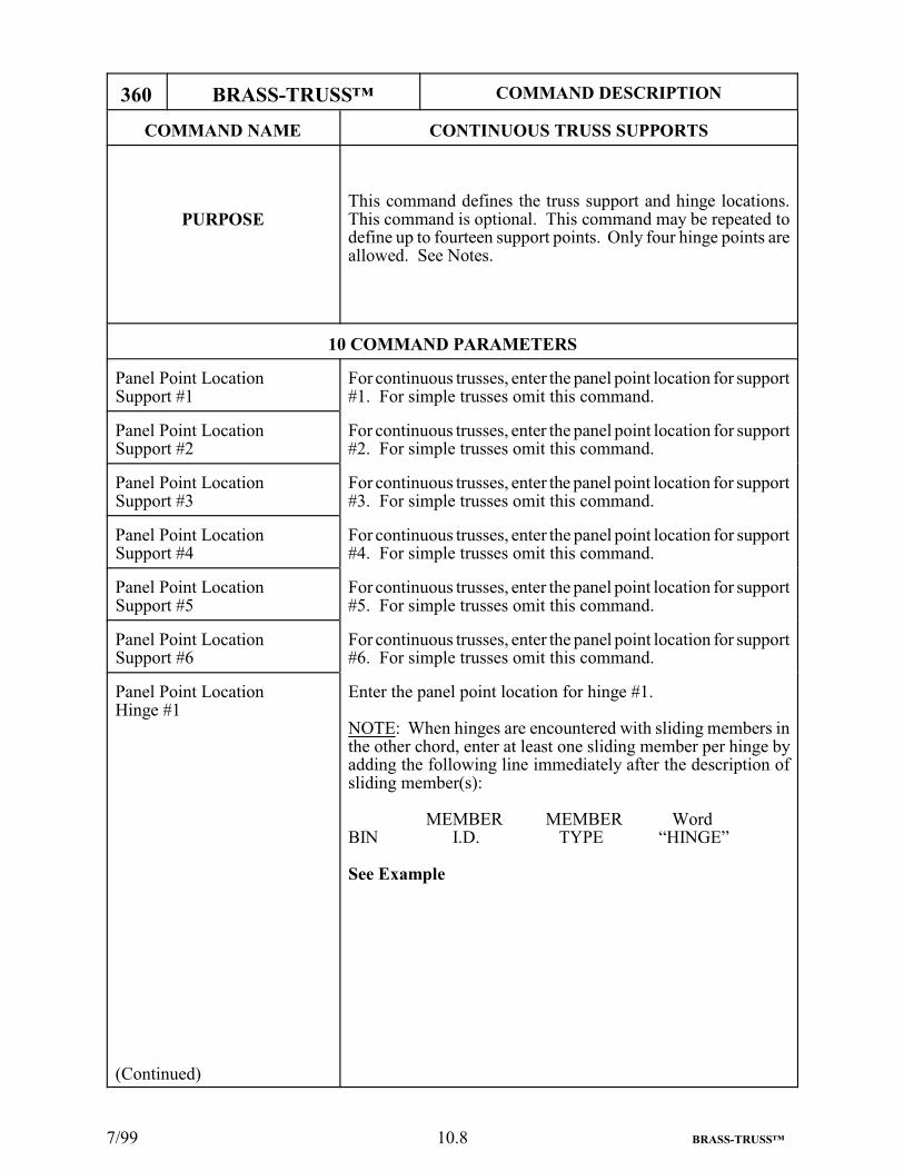
7/99 10.8 BRASS-TRUSS™
360 BRASS-TRUSS™ COMMAND DESCRIPTION
COMMAND NAME CONTINUOUS TRUSS SUPPORTS
PURPOSEThis command defines the truss support and hinge locations.This command is optional. This command may be repeated todefine up to fourteen support points. Only four hinge points areallowed. See Notes.
10 COMMAND PARAMETERS
Panel Point LocationSupport #1
For continuous trusses, enter the panel point location for support#1. For simple trusses omit this command.
Panel Point LocationSupport #2
For continuous trusses, enter the panel point location for support#2. For simple trusses omit this command.
Panel Point LocationSupport #3
For continuous trusses, enter the panel point location for support#3. For simple trusses omit this command.
Panel Point LocationSupport #4
For continuous trusses, enter the panel point location for support#4. For simple trusses omit this command.
Panel Point LocationSupport #5
For continuous trusses, enter the panel point location for support#5. For simple trusses omit this command.
Panel Point LocationSupport #6
For continuous trusses, enter the panel point location for support#6. For simple trusses omit this command.
Panel Point LocationHinge #1
(Continued)
Enter the panel point location for hinge #1.
NOTE: When hinges are encountered with sliding members inthe other chord, enter at least one sliding member per hinge byadding the following line immediately after the description ofsliding member(s):
MEMBER MEMBER WordBIN I.D. TYPE “HINGE”
See Example
7/99 10.9 BRASS-TRUSS™
COMMAND PARAMETERS (Cont.)
Panel Point LocationHinge #2
Enter the panel point location for hinge #2.
NOTE: When hinges are encountered with sliding members inthe other chord, enter at least one sliding member per hinge byadding the following line immediately after the description ofsliding member(s):
MEMBER MEMBER WordBIN I.D. TYPE “HINGE”
See Example
Panel Point LocationHinge #3
Enter the panel point location for hinge #3.
NOTE: When hinges are encountered with sliding members inthe other chord, enter at least one sliding member per hinge byadding the following line immediately after the description ofsliding member(s):
MEMBER MEMBER WordBIN I.D. TYPE “HINGE”
See Example
Panel Point LocationHinge #4
Enter the panel point location for hinge #4.
NOTE: When hinges are encountered with sliding members inthe other chord, enter at least one sliding member per hinge byadding the following line immediately after the description ofsliding member(s):
MEMBER MEMBER WordBIN I.D. TYPE “HINGE”
See Example

7/99 10.10 BRASS-TRUSS™
EXAMPLE
1234567 CONTINUOUS TRUSS SUPPORTS L00 L15 L30 L451234567 L11L12 CBXO 0 17.0 0 15 3.375 0 0 17.0 01234567 L11L12 CBXO HINGE
FIGURES
NOTES
For continuous trusses, ignore the output entitled “LEFT REACTION = RIGHT REACTION = ”. This output is meant for simple span trusses only.

7/99 10.11 BRASS-TRUSS™

11/01 10.12 BRASS-TRUSS™
370 BRASS-TRUSS™ COMMAND DESCRIPTION
COMMAND NAME CBX or CBH
PURPOSE
This command defines truss members composed of channelsand plates. This command is required when channel membersexist and may be repeated as often as needed to describe all thechannel members.
Use the command “CBX’ or “CBH”. The “X” or “H” are usedto determine the Yield Strength for this member. “X” is to beused when the Yield Strength is the same as that listed on theSTRESSES command or set by the Year of OriginalConstruction parameter on the YEARS command. “H” is to beused when the Yield Strength is the same as that listed in theHybrid Truss FY steel parameter on the STRESSES command.
15 COMMAND PARAMETERS
NOTE: The following fourparameters are placedBEFORE the command.
Member Beginning Location,Left or Top
Enter the letter that corresponds to the vertical location of thebeginning of the truss member of this type. “U” is for upper,“M” is for middle, and “L” is for lower panel points. If there aremore than 99 panels, change the “U” to “T”, change “M” to“C”, and change the “L” to “B” for those members over 99. SeePage 10.2 for numbering convention. DO NOT place a blankspace between this parameter and the following parameter.
Member Panel Point,Left or Top
Enter the two-digit number that corresponds to the horizontallocation of the beginning of the truss member of this type.Numbers less than ten start with 0. DO NOT place a blankspace between this parameter and the following parameter.
Member End Location,Right or Bottom
Enter the letter that corresponds to the vertical location of theend of the truss member of this type. “U” is for upper, “M” isfor middle, and “L” is for lower panel points. If there are morethan 99 panels, change the “U” to “T”, change “M” to “C”, andchange the “L” to “B” for those members over 99. DO NOTplace a blank space between this parameter and the followingparameter.
Member Panel Point,Right or Bottom
Enter the two-digit number that corresponds to the horizontallocation of the end of the truss member of this type. Numbersless than ten start with the 0. Insert a space, followed by thecommand after this parameter. See Example.
Flange Orientation
(Continued)
Two letters are used to determine which way the channel flangesin box sections are pointing. Enter “I” for inward and “O” foroutward. Do Not place a blank space between the command andthis parameter. Place a space after this parameter, as usual. SeeExample and Figure 1.

11/01 10.13 BRASS-TRUSS™
COMMAND PARAMETERS (Cont.)
Member Length Enter the length, in feet, of any vertical or horizontal member ofthis type whose length is different than the Panel Height or PanelLength dimensions, respectively, that were given on the MAINMEMBER TRUSS command. If the length of any vertical orhorizontal member is the same as these dimensions, or themember is a diagonal, enter 0.
Top Plates Width Enter the width, in inches, of the continuous top plates or the toptie plates. If lacing bars are used, and there are no continuous topflange plates, enter the out-to-out dimension of the channels. SeeFigure 2 for all dimensions. (Maximum = 30 inches, Minimum= 5 inches or 0 inches)
Top Plates Thickness Enter the total thickness, in inches, of all the continuous topplates. If there are no continuous top plates or if top lacing barsare used, enter 0. (Maximum = 4 inches, Minimum = 0.18 inchesor 0 inches)
Channel Depth Enter the actual depth of channel in inches. See Notes.(Maximum = 18 inches, Minimum = 3 inches)
Channel Flange Width
or“W” + Weight per Foot
Enter the flange width, in inches, of the channel. If the channelsection is specified on the “As Built” plans, enter the letter “W”followed by the weight per foot from these plans. See Notes.(Maximum = 4.2 inches, Minimum = 1.4 inches or Maximum =58 lbs., Minimum = 4.1 lbs.)
Side Plates Depth Enter the width, in inches, of any continuous side plates. If thereare none, enter 0. (Maximum = Channel Depth, Minimum = 0inches)
Side Plates Thickness Enter the total thickness, in inches, of all the continuous sideplates attached to one channel. If there are none, enter 0.(Maximum = 1 inch, Minimum = 0.25 inches or 0 inches)
Bottom Plates Width Enter the width, in inches, of the continuous bottom plates or thebottom tie plates. If lacing bars are used or there are nocontinuous bottom flange plates, enter the out-to-out dimensionof the channels. (Maximum = 30 inches, Minimum = 5 inches or0 inches)
Bottom Plates Thickness Enter the total thickness, in inches, of all the continuous bottomplates. If there are no continuous bottom plates or if bottomlacing bars are used, enter 0. (Maximum = 4 inches, Minimum= 0.18 inches or 0 inches)
Drop Distance From Datum If this is a vertical member in a combination truss (see Page10.1), enter the distance, in feet, from the datum line to thebottom of this member, preceeded with a blank space and aminus sign (i.e. “ -5"). If the bottom of thevertical is above thedatum line, use a plus symbol (i.e. “ +5").

8/00 10.14 BRASS-TRUSS™
EXAMPLE
1234567 U06U07 CBXO 0 17.0 0.38 10.0 2.74 0 0 16.5 01234567 L10L11 CBXO 0 22 0 15 W40 12 0.438 22 0
FIGURES

8/00 10.15 BRASS-TRUSS™
NOTES
There are two ways the user can select a channel truss member from the sections library. 1) The usermay input a section depth and flange width in Parameters 9 and 10. The program will search thelibrary for the first occurrence of this combination of values. If a section is not found in the library,the program tries to find a section within c” of the dimensions input. If a section is not found, anerror message appears in the output. 2) If a Channel is specified on the “As Built” plans, the user mayinput a one or two digit integer section depth corresponding to the beam depth as listed under“Designation” in the AISC Manual of Steel Construction in Parameter 9 and input the letter “W”followed by the weight per foot in Parameter 10. The program will search the library for the firstoccurrence of the combination of depth and weight. Note: The use of the letter “W” does not meanthat a W section will be selected. The letter “W” is merely a flag to tell the program to search for arolled channel section. If a section is not found, an error message appears in the output.
The shape you enter must exist in the standard shapes library, stsect.dat. This library is a binaryfile and is not easily readable. An ASCII copy of this file has been placed on the FTP Server forviewing.

11/01 10.16 BRASS-TRUSS™
380 BRASS-TRUSS™ COMMAND DESCRIPTION
COMMAND NAME ABX or ABH
PURPOSE
This command defines truss members composed of angles andplates. This command is required when angle members existand may be repeated as often as needed to describe all the anglemembers.
Use the command “ABX” or “ABH”. The “X” or “H” are usedto determine the Yield Strength for this member. “X” is to beused when the Yield Strength is the same as that listed on theSTRESSES command or set by the Year of OriginalConstruction parameter on the YEARS command. “H” is to beused when the Yield Strength is the same as that listed in theHybrid Truss FY Steel parameter on the STRESSES command.
19 COMMAND PARAMETERS
NOTE: The following fourparameters are placedBEFORE the command.
Member Beginning Location,Left or Top
Enter the letter that corresponds to the vertical location of thebeginning of the truss member of this type. “U” is for upper,“M” is for middle, and “L” is for lower panel points. If there aremore than 99 panels, change the “U” to “T”, change “M” to“C”, and change the “L” to “B” for those members over 99. SeePage 10.2 for numbering convention. DO NOT place a blankspace between this parameter and the following parameter.
Member Panel Point,Left or Top
Enter the two-digit number that corresponds to the horizontallocation of the beginning of the truss member of this type.Numbers less than ten start with the 0. DO NOT place a blankspace between this parameter and the following parameter.
Member End Location,Right or Bottom
Enter the letter that corresponds to the vertical location of theend of the truss member of this type. “U” is for upper, “M” isfor middle, and “L” is for lower panel points. If there are morethan 99 panels, change the “U” to “T”, change “M” to “C”, andchange the “L” to “B” for those members over 99. DO NOTplace a blank space between this parameter and the followingparameter.
Member Panel Point,Right or Bottom
(Continued)
Enter the two-digit number that corresponds to the horizontallocation of the end of the truss member of this type. Numberless than ten start with the 0. Insert a space, followed by thecommand after this parameter. See Example.

7/99 10.17 BRASS-TRUSS™
COMMAND PARAMETERS (Cont.)
Flange Orientation Two letters are used to determine which way the horizontalangles in box sections are pointing. Enter “I” for inward and“O” for outward. DO NOT place a blank space between thecommand and this parameter. Place a space after thisparameter, as usual. See Example and Figure 1.
Member Length Enter the length, in feet, of any vertical or horizontal member ofthis type whose length is different than the Panel Height orPanel Length dimensions, respectively, that were given on theMAIN MEMBER TRUSS command. If the length of anyvertical or horizontal member is the same as these dimensions,or the member is a diagonal, enter 0.
Top Plates Width Enter the width, in inches, of the continuous top plates or top tieplates. If lacing bars are used and there are no continuous topflange plates, enter the out-to-out dimension of the top angles.See Figure 2 for all dimensions. (Maximum = 50 inches,Minimum = 5 inches or 0)
Top Plates Thickness Enter the total thickness, in inches, of all the continuous topplates. If there are no continuous top plates, or if top lacing barsare used, enter 0. (Maximum = 4 inches, Minimum = 0.18inches or 0)
Top Angles WidthHorizontal Leg
Enter the width, in inches, of the top angle leg that is attachedto the top plates. If there are no angles, enter 0. (Maximum =9 inches, Minimum = 1.0 inches or 0)
Top Angles WidthVertical Leg
Enter the width, in inches, of the top angle leg that is attachedto the web plate. If there are no angles, enter 0. (Maximum =9 inches, Minimum = 1.0 inches or 0)
Top Angles Thickness Enter the thickness, in inches, of the top angle. If there are noangles, enter 0. (Maximum = 1.125 inches, Minimum = 0.125inches or 0)
Web Plates Depth Enter the back-to-back distance, in inches, between the top orbottom angles. If there are no angles, enter the depth of the webplate. (Maximum = 60 inches, Minimum = 5 inches or 0)
Web Plates Thickness Enter the thickness of the full-depth continuous web plates. Ifthere are no full-depth continuous web plates, or if lacing barsare used, enter 0.(Maximum = 4 inches, Minimum = 0.18 inches or 0)
Bottom Angles WidthHorizontal Leg
(Continued)
Enter the width, in inches, of the bottom angle leg that isattached to the bottom plates. If there are no angles, enter 0.(Maximum = 9 inches, Minimum = 1.0 inches or 0)

11/01 10.18 BRASS-TRUSS™
COMMAND PARAMETERS (Cont.)
Bottom Angles WidthVertical Leg
Enter the width, in inches, of the bottom angle leg that isattached to the web plates. If there are no angles, enter 0.(Maximum = 9 inches, Minimum = 1.0 inches or 0)
Bottom Angles Thickness Enter the thickness, in inches, of the bottom angle. If there areno angles, enter 0. (Maximum = 1.125 inches, Minimum =0.125 inches or 0)
Bottom Plates Width Enter the width, in inches, of the continuous bottom plates orbottom tie plates. If lacing bars are used, and there are nocontinuous top flange plates, enter the out-to-out dimension ofthe angles. (Maximum = 50 inches, Minimum = 5 inches or 0)
Bottom Plates Thickness Enter the total thickness, in inches, of all the continuous bottomplates. If there are no continuous bottom plates or if bottomlacing bars are used, enter 0. (Maximum = 4 inches, Minimum= 0.18 inches or 0)
Drop Distance From Datum If this is a vertical member in a combination truss (see Page10.1), enter the distance, in feet, from the datum line to thebottom of this member, preceeded with a blank space and aminus sign (i.e. “ -5"). If the bottom of the vertical is above thedatum line, use a plus symbol (i.e. “ +5").

7/99 10.19 BRASS-TRUSS™
EXAMPLE
1234567 L02U02 ABXI 9.0 8.0 0 3.0 3.0 0.31 0 0 0 0 0 0 0
FIGURES
NOTES

11/01 10.20 BRASS-TRUSS™
390 BRASS-TRUSS™ COMMAND DESCRIPTION
COMMAND NAME ROLLED or ROLHED
PURPOSE
This command defines truss members composed of a rolledbeam and plates. This command is required when rolled beammembers exist and may be repeated as often as needed todescribe all the rolled beam members.
Use the command “ROLLED” or “ROLHED”. The “L” or “H”are used to determine the Yield Strength for this member. “L”is to be used when the Yield Strength is the same as that listedon the STRESSES command or set by the Year of OriginalConstruction parameter on the YEARS command. “H” is to beused when the Yield Strength is the same as that listed in theHybrid Truss FY Steel parameter on the STRESSES command.
13 COMMAND PARAMETERS
NOTE: The following fourparameters are placedBEFORE the command.
Member Beginning Location,Left or Top
Enter the letter that corresponds to the vertical location of thebeginning of the truss member of this type. “U” is for upper,“M” is for middle, and “L” is for lower panel points. If there aremore than 99 panels, change the “U” to “T”, change “M” to“C”, and change “L” to “B” for those members over 99. SeePage 10.2 for numbering convention. DO NOT place a blankspace between this parameter and the following parameter.
Member Panel Point, Left or Top
Enter the two-digit number that corresponds to the horizontallocation of the beginning of the truss member of this type.Number less than ten start with the 0. DO NOT place a blankspace between this parameter and the following parameter.
Member End Location,Right or Bottom
Enter the letter that corresponds to the vertical location of theend of the truss member of this type. “U” is for upper, “M” isfor middle, and “L” is for lower panel points. If there are morethan 99 panels, change the “U” to “T”, change “M” to “C”, andchange the “L” to “B” for those members over 99. DO NOTplace a blank space between this parameter and the followingparameter.
Member Panel Point,Right or Bottom
(Continued)
Enter the two-digit number that corresponds to the horizontallocation of the end of the truss member of this type. Numbersless than ten start with the 0. Insert a space, followed by thecommand after this parameter. Place a space after thiscommand, as usual. See Example.

11/01 10.21 BRASS-TRUSS™
COMMAND PARAMETERS (Cont.)
Member Length Enter the length, in feet, of any vertical or horizontal member ofthis type whose length is different than the Panel Height orPanel Length dimensions, respectively, that were given on theMAIN MEMBER TRUSS command. If the length of anyvertical or horizontal member is the same as these dimensions,or the member is a diagonal, enter 0.
Top Plates Width Enter the average width, in inches, of all the continuous topflange cover plates. If none exist, enter 0. See Figures for alldimensions. (Maximum = 36 inches, Minimum = Rolled Beam FlangeWidth minus 2 inches or 0)
Top Plates Thickness Enter the total thickness, in inches, of all the continuous topflange cover plates. If none exist, enter 0. (Maximum = 3inches, Minimum = 0.5 inches or 0)
Rolled Beam Depth Enter the depth, in inches, of the rolled beam. See Notes.(Maximum = 37 inches, Minimum = 5 inches)
Rolled Beam Flange Widthor“W” + Weight per Foot
Enter the width, in inches, of the rolled beam flange. If therolled beam section is specified on the “As Built” plans, enterthe letter “W” followed by the weight per foot from these plans.See Notes. (Maximum = 23 inches, Minimum = 2 inches orMaximum = 730 lbs., Minimum = 8 lbs)
Rolled BeamFlange Thickness
Enter the average thickness, in inches, of the rolled beam flange.If the weight per foot was entered under Rolled Beam FlangeWidth, enter 0. (Maximum = 5 inches, Minimum = 0.18 inchesor 0)
Bottom Plates Width Enter the average width, in inches, of all the continuous bottomflange cover plates. If none exist, enter 0. (Maximum = 36inches, Minimum = Rolled Beam Flange Width minus 2 inchesor 0)
Bottom Plates Thickness Enter the total thickness, in inches, of all the continuous bottomflange cover plates. If none exist, enter 0. (Maximum = 3inches, Minimum = 0.5 inches or 0)
Drop Distance From Datum If this is a vertical member in a combination truss (see Page10.1), enter the distance, in feet, from the datum line to thebottom of this member, preceeded with a blank space and aminus sign (i.e. “ -5"). If the bottom of the vertical is above thedatum line, use a plus symbol (i.e. “ +5").

8/00 10.22 BRASS-TRUSS™
EXAMPLE
1234567 L01U01 ROLLED 8.0 0 0 21 8.355 0.835 0 0
1234567 L02L03 ROLLED 0 0 0 24 W104 0 16 1.08 (WN 24x104 - First 24x104 section listed in sections library)
1234567 L02L03 ROLLED 0 0 0 24 9.775 0.942 16 1.08 (W 24x104 - Second 24x104 section listed in sections library)
FIGURES

8/00 10.23 BRASS-TRUSS™
NOTES
There are two ways the user can select a rolled truss member from the sections library. 1) Theuser may input a section depth and flange width in Parameters 8 and 9. The program willsearch the library for the first occurrence of this combination of values. If a section is notfound in the library, the program tries to find a section within c” of the dimensions input. If asection is not found, an error message appears in the output. 2) If a W section is specified onthe “As Built” plans, the user may input a one or two digit integer section depth correspondingto the beam depth as listed under “Designation” in the AISC Manual of Steel Construction inParameter 8 and input the letter “W” followed by the weight per foot in Parameter 9. Theprogram will search the library for the first occurrence of the combination of depth andweight. If a section is not found, an error message appears in the output. Note: In thestandard sections library, some standard shapes begin with “W” and “WN” (i.e., W24X76 andWN24X76). In 1985, AISC changed the dimensions of several steel shapes while keeping thesame designation. To differentiate between the two types (especially when the older shape isneeded to perform a rating) an “N” was added to the shape designation to indicate a NEWshape. In the event the user wishes to select the second occurrence of a section listed in thelibrary, use the first method described above and input the specific flange width as it appearsin the library. See the example above. Note: A zero must be entered in Parameter 10 whenan AISC shape is entered in Parameters 8 and 9.
The shape you enter must exist in the standard shapes library, stsect.dat. This library is abinary file and is not easily readable. An ASCII copy of this file has been placed on the FTPServer for viewing.

11/01 10.24 BRASS-TRUSS™
400 BRASS-TRUSS™ COMMAND DESCRIPTION
COMMAND NAME ISEC or ISEH
PURPOSE
This command defines truss members composed of platesconfigured as an I-section, angles, and cover plates. Thiscommand is required when welded plate members exist andmay be repeated as often as needed to describe all the I-sectionmembers.
Use the command “ISEC” or “ISEH”. The “C” or “H” are usedto determine the Yield Strength for this member. “C” is to beused when the Yield Strength is the same as that listed on theSTRESSES command or set by the Year of OriginalConstruction parameter on the YEARS command. “H” is to beused when the Yield Strength is the same as that listed in theHybrid Truss FY Steel parameter on the STRESSES command.
18 COMMAND PARAMETERS
NOTE The following fourparameters are placedBEFORE the command.
Member BeginningLocation, Left or Top
Enter the letter that corresponds to the vertical location of thebeginning of the truss member of this type. “U” is for upper,“M” is for middle, and “L” is for lower panel points. If there aremore than 99 panels, change the “U” to “T”, change the “M” to“C”, and change the “L” to “B” for those members over 99. SeePage 10.2 for numbering convention. DO NOT place a blankspace between this parameter and the following parameter.
Member Panel Point,Left or Top
Enter the two-digit number that corresponds to the horizontallocation of the beginning of the truss member of this type.Numbers less than ten start with the 0. DO NOT place a blankspace between this parameter and the following parameter.
Member End Location, Rightor Bottom
(Continued)
Enter the letter that corresponds to the vertical location of the endof the truss member of this type. “U” is for upper, “M” is formiddle, and “L” is for lower panel points. If there are more than99 panels, change the “U” to “T”, change “M” to “C”, andchange the “L” to “B” for those members over 99. DO NOTplace a blank space between this parameter and the followingparameter.

7/99 10.25 BRASS-TRUSS™
COMMAND PARAMETERS (Cont.)
Member Panel Point, Rightor Bottom
Enter the two-digit number that corresponds to the horizontallocation of the end of the truss member of this type. Numbersless than ten start with the 0. Insert a space, followed by thecommand after this parameter. Place a space after thiscommand, as usual. See Example.
Member Length Enter the length, in feet, of any vertical or horizontal member ofthis type whose length is different than the Panel Height or PanelLength dimensions, respectively, that were given on the MAINMEMBER TRUSS command. If the length of any vertical orhorizontal member is the same as these dimensions, or themember is a diagonal, enter 0.
Top Plates Width Enter the average width, in inches, of all the continuous topflange plates. If none exist, enter 0. See Figures for alldimensions. (Maximum = 24 inches, Minimum = 5 inches or 0)
Top Plates Thickness Enter the total thickness, in inches, of all the continuous topflange plates. If none exist, enter 0. (Maximum = 3 inches,Minimum = 0.18 inches or 0)
Top Angles WidthHorizontal Leg
Enter the width, in inches, of the angle leg that is attached to thetop flange plates. If there are no angles enter 0. (Maximum = 9inches, Minimum = 1.0 inches or 0)
Top Angles WidthVertical Leg
Enter the width, in inches, of the angle leg that is attached to theweb plate(s). If there are no angles, enter 0. (Maximum = 9inches, Minimum = 1.0 inches or 0)
Top Angles Thickness Enter the thickness, in inches, of the top flange angle. If there areno angles, enter 0. (Maximum = 1.125 inches, Minimum = 0.125inches or 0)
Web Plates Depth Enter the back-to-back distance, in inches, between the top andbottom angles. If there are no angles, enter the depth of the webplate. (Maximum = 40 inches, Minimum = 5 inches or 0)
Web Plates Thickness Enter the thickness, in inches, of the full depth web plate(s). Ifthere are no full depth web plates or lacing bars are used, enter 0.(Maximum = 1 inch, Minimum = 0.18 inches or 0)
Bottom Angles WidthHorizontal Leg
Enter the width, in inches, of the angle leg that is attached to thebottom flange plates. If there are no angles, enter 0. (Maximum= 9 inches, Minimum = 1.0 inches or 0)
Bottom Angles WidthVertical Leg
(Continued)
Enter the width, in inches, of the angle leg that is attached to theweb plate(s). If there are no angles, enter 0. (Maximum = 9inches, Minimum = 1.0 inches or 0)

11/01 10.26 BRASS-TRUSS™
COMMAND PARAMETERS (Cont.)
Bottom Angle Thickness Enter the thickness, in inches, of the bottom angle. If there areno angles, enter 0. (Maximum = 1.125 inches, Minimum = 0.125inches or 0)
Bottom Plates Width Enter the average width, in inches, of all the continuous bottomflange plates. If none exist, enter 0. (Maximum = 24 inches,Minimum = 5 inches or 0)
Bottom Plates Thickness Enter the total thickness, in inches, of all the continuous bottomflange plates. If none exist, enter 0. (Maximum = 3 inches,Minimum = 0.18 inches or 0)
Drop Distance From Datum If this is a vertical member in a combination truss (see Page10.1), enter the distance, in feet, from the datum line to thebottom of this member, preceeded with a blank space and aminus sign (i.e. “ -5"). If the bottom of the vertical is above thedatum line, use a plus symbol (i.e. “ +5").

7/99 10.27 BRASS-TRUSS™
EXAMPLE
1234567 U05U06 ISEC 0 15.0 .625 7 3.5 .625 7.5 0.75 7 3.5 .625 15.5 .625
FIGURES
NOTES

11/01 10.28 BRASS-TRUSS™
410 BRASS-TRUSS™ COMMAND DESCRIPTION
COMMAND NAME EYEBAR or EYEHAR
PURPOSE
This command defines truss members composed of eyebars.This command is required when eyebar members exist and maybe repeated as often as needed to describe all the eyebarmembers.
Use the command “EYEBAR” or “EYEHAR”. The “B” or “H”are used to determine the Yield Strength for this member. “B”is to be used when the Yield Strength is the same as that listedon the STRESSES command or set by the Year of OriginalConstruction parameter on the YEARS command. “H” is to beused when the Yield Strength is the same as that listed in theHybrid Truss FY Steel parameter on the STRESSES command.
9 COMMAND PARAMETERS
NOTE: The following fourparameters are placedBEFORE the command.
Member Beginning Location,Left or Top
Enter the letter that corresponds to the vertical location of thebeginning of the truss member of this type. “U” is for upper,“M” is for middle, and “L” is for lower panel points. If there aremore that 99 panels, change the “U” to “T”, change “M” to “C”,and change the “L” to “B” for those members over 99. See Page10.2 for numbering convention. DO NOT place a blank spacebetween this parameter and the following parameter.
Member Panel Point, Left or Top
Etner the two-digit number that corresponds to the horizontallocation of the beginning of the truss member of this type.Numbers less than ten start with 0. DO NOT place a blankspace between this parameter and the following parameter.
Member End Location, Rightor Bottom
Enter the letter that corresponds to the vertical location of theend of the truss member of this type. “U” is for upper, “M” isfor middle, and “L” is for lower panel points. If there are morethan 99 panels, change the “U” to “T”, change “M” to “C”, andchange the “L” to “B” for those members over 99. DO NOTplace a blank space between this parameter and the followingparameter.
Member Panel Point,Right or Bottom
(Continued)
Enter the two-digit number that corresponds to the horizontallocation of the end of the truss member of this type. Numbersless than ten start with the 0. Insert a space, followed by thecommand after this parameter. Place a space after thiscommand, as usual. See Example.

11/01 10.29 BRASS-TRUSS™
COMMAND PARAMETERS (Cont.)
Member Length Enter the length, in feet, of any vertical or horizontal member ofthis type whose length is different than the Panel Height orPanel Length dimensions, respectively, that were given on theMAIN MEMBER TRUSS command. If the length of anyvertical or horizontal member is the same as these dimensions,or the member is a diagonal, enter 0.
Number of Elements Enter the number of elements that make up the member.(Maximum = 9, Minimum = 1)
Eyebar Width Enter the largest dimension, in inches, of the individual elementcross section. See Figures for all dimensions. (Maximum = 8inches, Minimum = 0.50 inches)
Eyebar Thickness Enter the smallest dimension, in inches, of the individualelement cross section. (Maximum = 2 inches, Minimum = 0.25inches)
NOTE: For loop bars, provide the dimensions for 80% of theindividual bar area.
Drop Distance From Datum If this is a vertical member in a combination truss (see Page10.1), enter the distance, in feet, from the datum line to thebottom of this member, preceeded with a blank space and aminus sign (i.e. “ -5"). If the bottom of the vertical is above thedatum line, use a plus symbol (i.e. “ +5").

7/99 10.30 BRASS-TRUSS™
EXAMPLE
1234567 L01U02 EYEBAR 0 2 3.0 1.0
FIGURES
NOTES

7/99 10.31 BRASS-TRUSS™

11/01 10.32 BRASS-TRUSS™
420 BRASS-TRUSS™ COMMAND DESCRIPTION
COMMAND NAME THREADED or THRHADED
PURPOSE
This command defines truss members composed of threadedbars. This command is required when threaded bar membersexist and may be repeated as often as needed to describe all thethreaded members.
Use the command “THREADED” or “THRHADED”. The “E”or “H” are used to determine the Yield Strength for thismember. “E” is to be used when the Yield Strength is the sameas that listed on the STRESSES command or set by the Year ofOriginal Construction parameter on the YEARS command. “H”is to be used when the Yield Strength is the same as that listedin the Hybrid Truss FY Steel parameter on the STRESSEScommand.
9 COMMAND PARAMETERS
NOTE: The following fourparameters are placedBEFORE the command.
Member BeginningLocation, Left or Top
Enter the letter that corresponds to the vertical location of thebeginning of the truss member of this type. “U” is for upper,“M” is for middle, and “L” is for lower panel points. If there aremore than 99 panels, change the “U” to “T”, change “M” to “C”,and change “L” to “B” for those members over 99. See page10.2 for numbering convention. DO NOT place a blank spacebetween this parameter and the following parameter.
Member Panel Point, Left orTop
Enter the two-digit number that corresponds to the horizontallocation of the beginning of the truss member of this type.Numbers less than ten start with the 0. DO NOT place a blankspace between this parameter and the following parameter.
Member End Location, Rightor Bottom
(Continued)
Enter the letter that corresponds to the vertical location of the endof the truss member of this type. “U” is for upper, “M” is formiddle, and “L” is for lower panel points. If there are more than99 panels, change the “U” to “T”, change “M” to “C”, andchange the “L” to “B” for those member over 99. DO NOT placea blank space between this parameter and the followingparameter.

11/01 10.33 BRASS-TRUSS™
COMMAND PARAMETERS (Cont.)
Member Panel Point, Rightor Bottom
Enter the two-digit number that corresponds to the horizontallocation of the end of the truss member of this type. Numbersless than ten start with 0. Insert a space, followed by thecommand after this parameter. Place a space after this command,as usual. See Example.
Member Length Enter the length, in feet, of any vertical or horizontal member ofthis type whose length is different than the Panel Height or PanelLength dimensions, respectively, that were given on the MAINMEMBER TRUSS command. If the length of any vertical orhorizontal member is the same as these dimensions, or themember is a diagonal, enter 0.
Number of Bars Enter the number of elements that make up the member.(Maximum = 9, Minimum = 1)
Outside Thread Diameter Enter the outside diameter, in inches, of the individual threadedelements at the threaded portions. See Figures for alldimensions. (Maximum = 4 inches, Minimum = 0.75 inches)
End Configuration Enter either “UPSET” or “CUT” to describe the manner in whichthe threads are applied to the ends of the bars. No other wordsare acceptable.
Drop Distance From Datum If this is a vertical member in a combination truss (see Page10.1), enter the distance, in feet, from the datum line to thebottom of this member, preceeded with a blank space and aminus sign (i.e. “ -5"). If the bottom of the vertical is above thedatum line, use a plus symbol (i.e. “ +5").

7/99 11.34 BRASS-TRUSS™
EXAMPLE
1234567 L01U02 THREADED 2 1.25 CUT
FIGURES
NOTES

7/99 11.1 BRASS-TRUSS™
11. CODING INSTRUCTIONS FOR MAIN MEMBERS - GIRDERS
11.1. GENERAL DETERIORATION INFORMATION FOR GIRDERMEMBERS
If there is deterioration of any girder member, fill out one command as you would normally for agirder member, with the “RANGE” parameter used to signify the end of the deteriorated area. The“RANGE” parameter from the normal command before this command will locate the beginning ofthe deteriorated area. The next command will be the command with the deterioration data for thearea located by the preceding command of this pair. On this deterioration command, fill out theheadings up through and including the parameter heading Span Number. For the parameter Range,enter the word “RUST”. For the remainder of this command, see the detailed explanation of theinformation required for deterioration in section “DETERIORATION INFORMATION”, Page 13.1.

5/05 11.2 BRASS-TRUSS™
430 BRASS-TRUSS™ COMMAND DESCRIPTION
COMMAND NAME MAIN MEMBER
PURPOSE This command defines the type of girder configuration forgirder bridges. This command is required for girder bridges.
10 COMMAND PARAMETERS
Girder Type Enter “DECK” or “THRU” to describe the general type ofbridge construction with girders as the main supportingmembers. No other words are acceptable. See Figure 1.
Girder Main Member Enter “GIRDER”. No other words are acceptable.
Girder Construction Enter “RIVETED”, “WELDED” or “TIMBER” to describe thetype of girder construction. No other words are acceptable. Ifthe girder is a rolled beam without cover plates, enter“WELDED”. See Note 1.
Girder Orientation If the Girder Type is “DECK” or “THRU”, enter “LEFT”,“MIDDLE”, “RIGHT” or “EITHER”. No other words areacceptable.
Haunch Depth If the Girder Type is “THRU”, enter 0. Otherwise, if the spacebetween the bottom of the concrete deck and the top of thegirder top flange is filled with concrete, enter this distance, ininches. If the bottom of the concrete slab is flush with, orbelow, the top of the girder top flange or this space is not filledwith concrete, enter 0. (Maximum = 12 inches, Minimum = 0inches) See Figure 2.
Number of Continuous Spans Enter the number of spans through which the girders are actingcontinuously. Use 0 for a simple span. (Maximum = 8 spans,Minimum = 0 spans, 1 is not acceptable).
Spacing of Diaphragms orKnee Braces
(Continued)
Enter the spacing, in feet, of any diaphragms or knee bracing.If none exist, enter 0 and note it in the COMMENTS command.

7/99 11.3 BRASS-TRUSS™
COMMAND PARAMETERS (Cont.)
Compression Flange Restraint Enter “YES” or “NO”, “Y” or “N”. Nothing else is acceptable.Use “YES” or “Y” if any of the following conditions exist:
1) The presence of shear connectors.2) The girders are encased, have blast protection, or are
enclosed by jack arch construction. See Figure 3.3) The concrete deck extends down to the bottom of the top
flange.4) Sleepers or grating is adequately attached to the top
flange.
Use “NO” or “N” for ALL other conditions.
Number of Girders Enter the number of girders that support the bridge cross-section.
Fascia Girder Overhang Enter the distance, in feet from the centerline of the fascia girderto the outer-most part of the deck, sidewalk, or parapet.

7/99 11.4 BRASS-TRUSS™
EXAMPLE
1234567 MAIN MEMBER THRU GIRDER WELDED EITHER 0 0 20 N 2 0
FIGURES
(Continued)

7/99 11.5 BRASS-TRUSS™
FIGURES(Cont.)
NOTES
1. For riveted sections, the net section is computed by deducting the number of holes for each legan angle can have. The same number of holes are deducted from the plates that attach to thoseangles. This applies to axial loaded members only.
7/99 11.6 BRASS-TRUSS™
440 BRASS-TRUSS™ COMMAND DESCRIPTION
COMMAND NAME HINGE
PURPOSE This command defines the location up to two hinges per span.This command is optional and may be repeated for additionalspans.
3 COMMAND PARAMETERS
Span Number Enter the span number where the hinge is located.
Distance from BeginningSpan to Hinge #1
Enter the distance, in feet, to the first hinge from the beginningof the span.
Distance from BeginningSpan to Hinge #2
Enter the distance, in feet, to the second hinge from thebeginning of the span. If there is only one hinge in this span,enter 0.

7/99 11.7 BRASS-TRUSS™
EXAMPLE
1234567 HINGE 2 15 85
FIGURES
NOTES

7/99 11.8 BRASS-TRUSS™
450 BRASS-TRUSS™ COMMAND DESCRIPTION
COMMAND NAME MAIN MEMBER CONCRETE PROTECTION
PURPOSE This command defines the concrete protection on the girdermain member. This command is optional.
2 COMMAND PARAMETERS
Flange Depth (Encased) orThickness (Blast)
If “BLAST” is entered in the Type parameter on theCONCRETE DECK command, enter the distance, in inches,from the bottom of the concrete to the top of the concrete that iscovering the bottom flange. If “ENCASED” is entered in theType parameter on the CONCRETE DECK command, enter thedistance, in inches, from the bottom of the concrete covering thebottom flange up to either the top of the encasement or thebottom of the concrete slab if the encasement extends up to it.See Figures.
Web Thickness If “BLAST” is entered in the Type parameter on theCONCRETE DECK command, enter the distance, in inches,from one side of the concrete covering the web to the otherabove the bottom flange. If “ENCASED” is entered in the Typeparameter on the CONCRETE DECK command, enter thedistance, in inches, from one side of the concrete to the other.See Figures.
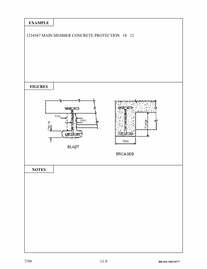
7/99 11.9 BRASS-TRUSS™
EXAMPLE
1234567 MAIN MEMBER CONCRETE PROTECTION 18 12
FIGURES
NOTES

7/99 11.10 BRASS-TRUSS™
460 BRASS-TRUSS™ COMMAND DESCRIPTION
COMMAND NAME RIVETED
PURPOSE This command defines the components of a riveted girder. Atleast one girder type command is required.
14 COMMAND PARAMETERS
Span Number Enter the span number of the span being rated.
Range Range is defined as a portion or length of a span, in feet, forwhich there are no changes in any elements of the girder. Theposition of the range within the span is defined by giving thedistance (range) from the support to the far end of the range. Inthe case of a linear or parabolic variation in the web depth, arange is the portion of the span for which the slope or parabolicconstant remains constant. Each span is to be treated separately.Up to 30 ranges (sections) may be described with the last Rangedimension equal to the span length.
Top Plates Width Enter the average width, in inches, of all the top flange plates.See Figures for all dimensions. (Maximum = 36 inches,Minimum = 8 inches or 0)
Top Plates Thickness Enter the total thickness, in inches, of all the top flange plates.(Maximum = 4 inches, Minimum = 0.18 inches or 0)
Top Angles WidthHorizontal Leg
Enter the width, in inches, of the top flange angle leg that isattached to the top flange plate. (Maximum = 9 inches,Minimum = 1.0 inches)
Top Angles WidthVertical Leg
Enter the width, in inches, of the top flange angle leg that isattached to the web plate. (Maximum = 9 inches, Minimum =1.0 inches)
Top Angle Thickness Enter the thickness, in inches, of the top flange angle.(Maximum = 1.125 inches, Minimum = 0.125 inches)
Web Plates Depth
(Continued)
Enter the distance, in inches, back-to-back of the angle legscomprising the girder flanges. (Maximum = 150 inches,Minimum = 24 inches) See Figure.

2/98 11.11 BRASS-TRUSS™
COMMAND PARAMETERS (Cont.)
Web Plates Thickness Enter the thickness, in inches, of the full-depth web plate.(Maximum = 1.5 inches, Minimum = 0.18 inches)
Bottom Angles WidthHorizontal Leg
Enter the width, in inches, of the bottom flange angle leg that isattached to the bottom flange plate. (Maximum = 9 inches,Minimum = 1.0 inches)
Bottom Angles WidthVertical Leg
Enter the width, in inches, of the bottom flange angle leg that isattached to the web plate. (Maximum = 9 inches, Minimum =1.0 inches)
Bottom Angles Thickness Enter the thickness, in inches, of the bottom flange angle.(Maximum = 1.125 inches, Minimum = 0.125 inches)
Bottom Plates Width Enter the average width, in inches, of all the bottom flangeplates. (Maximum = 36 inches, Minimum = 8 inches or 0)
Bottom Plates Thickness Enter the total thickness, in inches, of all the bottom flangeplates. (Maximum = 4 inches, Minimum = 0.18 inches or 0)
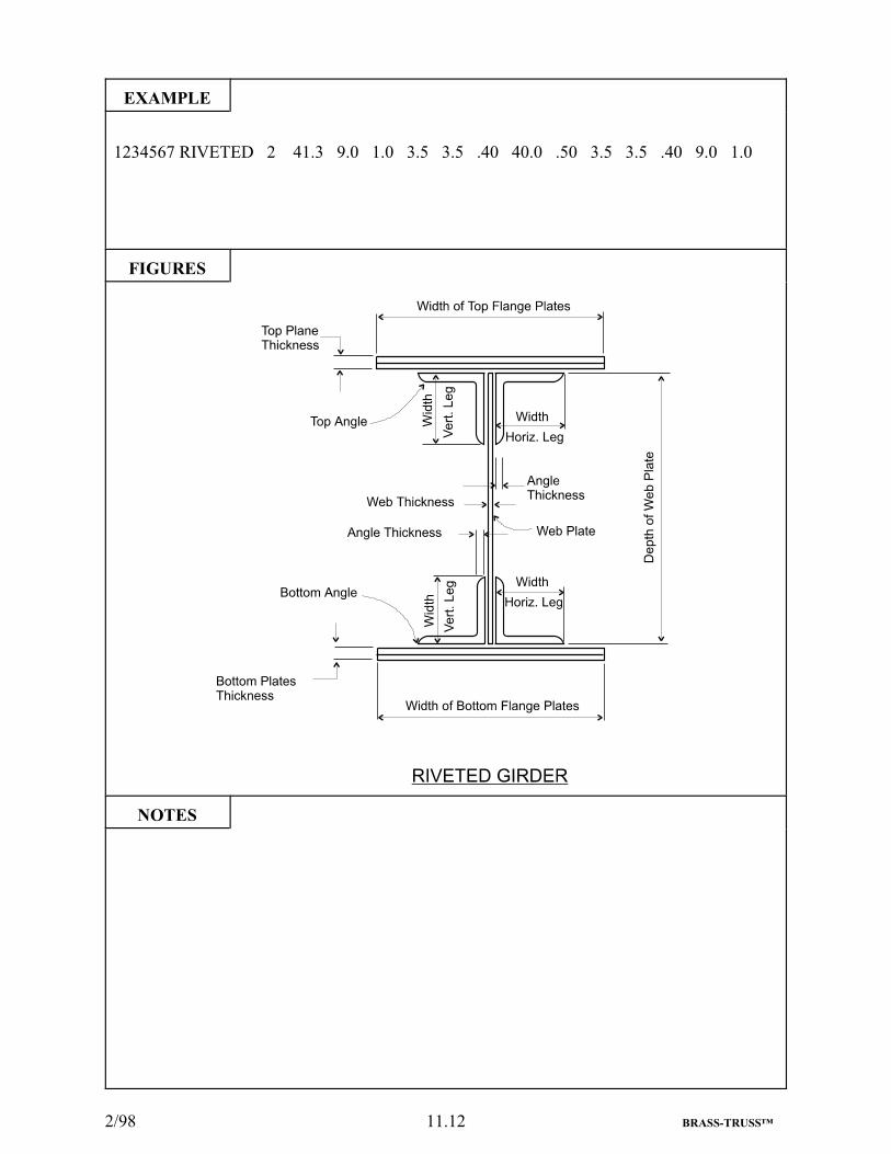
2/98 11.12 BRASS-TRUSS™
EXAMPLE
1234567 RIVETED 2 41.3 9.0 1.0 3.5 3.5 .40 40.0 .50 3.5 3.5 .40 9.0 1.0
FIGURES
NOTES

7/99 11.13 BRASS-TRUSS™

8/00 11.14 BRASS-TRUSS™
470 BRASS-TRUSS™ COMMAND DESCRIPTION
COMMAND NAME ROLLED
PURPOSE This command defines the rolled beam girder. At least onegirder type command is required.
11 COMMAND PARAMETERS
Span Number Enter the span number of the span rated.
Range Range is defined as a portion or length of a span, in feet, forwhich there are no changes in any elements of the girder. Theposition of the range within the span is defined by giving thedistance (range) from the support to the far end of the range.Each span is to be treated separately. Up to 30 ranges (sections)may be described with the last Range dimension equal to thespan length.
Top Plates Width Enter the average width, in inches, of all the top plates. SeeFigures for all dimensions. (Maximum = 30 inches, Minimum = 6 inches or 0)
Top Plates Thickness Enter the total thickness, in inches, of all the top flange plates.(Maximum = 2 inches, Minimum = 0.375 inches or 0)
Rolled Beam Depth Enter the depth, in inches, of the rolled beam girder. See Notes.(Maximum = 37 inches, Minimum = 3 inches)
Rolled Beam Flange Width or“W” + Weight per Foot
Enter the flange width, in inches, of the rolled beam girder. Ifthe Rolled Beam section is specified on the “As Built” plans,enter the letter “W” followed by the weight per foot from theseplans. See Notes. (Maximum = 18 inches, Minimum = 2inches or Maximum = 730 lbs., Minimum = 5 lbs.)
Rolled Beam FlangeThickness
Enter the average flange thickness, in inches, of the rolled beamgirder. If the weight per foot was entered under “ROLLEDBEAM FLANGE WIDTH”, enter 0. (Maximum = 5 inches, Minimum = 0.18 inches or 0)
Bottom Plates Width Enter the average width, in inches, of all the bottom flangeplates. (Maximum = 30 inches, Minimum = 6 inches or 0)
Bottom Plates Thickness
(Continued)
Enter the thickness, in inches, of all the bottom flange plates.(Maximum = 2 inches, Minimum = 0.375 inches or 0)

7/99 11.15 BRASS-TRUSS™
COMMAND PARAMETERS (Cont.)
Composite Enter “N” or “Y” to designate no or yes for composite action.No other letters are acceptable.
FY Enter the Yield Strength, in ksi, of the flange plates if they aredifferent than the values given on the STRESSES command. Ifthey are the same, or there are no flange plates, enter 0.

8/00 11.16 BRASS-TRUSS™
EXAMPLE
1234567 ROLLED 1 23.0 0 0 15.0 5.75 0.45 0 0 N 0
1234567 ROLLED 1 55.0 0 0 24 W104 0 0 0 N 0 (WN 24x104 - First 24x104 section listed in sections library)
1234567 ROLLED 1 55.0 0 0 24 9.775 0.942 0 0 N 0 (W 24x104 - Second 24x104 section listed in sections library)
FIGURES

8/00 11.17 BRASS-TRUSS™
NOTES
There are two ways the user can select a rolled beam girder from the sections library. 1) The usermay input a section depth and flange width in Parameters 5 and 6. The program will search thelibrary for the first occurrence of this combination of values. If a section is not found in thelibrary, the program tries to find a section within c” of the dimensions input. If a section is notfound, an error message appears in the output. 2) If a W section is specified on the “As Built”plans, the user may input a one or two digit integer section depth corresponding to the beam depthas listed under “Designation” in the AISC Manual of Steel Construction in Parameter 5 and inputthe letter “W” followed by the weight per foot in Parameter 6. The program will search thelibrary for the first occurrence of the combination of depth and weight. If a section is not found,an error message appears in the output. In this case, enter the beam as “WELDED” and enter theweb thickness. If the web thickness is not input, BRASS-TRUSS™ will assume the webthickness to be 0.678 x Flange Thickness. Note: In the standard sections library, some standardshapes begin with “W” and “WN” (i.e., W24X76 and WN24X76). In 1985, AISC changed thedimensions of several steel shapes while keeping the same designation. To differentiate betweenthe two types (especially when the older shape is needed to perform a rating) an “N” was addedto the shape designation to indicate a NEW shape. In the event the user wishes to select thesecond occurrence of a section listed in the library, use the first method described above andinput the specific flange width as it appears in the library. See the example above. Note: A zeromust be entered in Parameter 7 when an AISC shape is entered in Parameters 5 and 6.
The shape you enter must exist in the standard shapes library, stsect.dat. This library is abinary file and is not easily readable. An ASCII copy of this file has been placed on the FTPServer for viewing.

7/99 11.18 BRASS-TRUSS™
480 BRASS-TRUSS™ COMMAND DESCRIPTION
COMMAND NAME WELDED
PURPOSE This command defines the components of a welded plate girder.At least one girder type command is required.
10 COMMAND PARAMETERS
Span No. Enter the span number of the span being rated.
Range Range is defined as a portion or length of a span, in feet, forwhich there are no changes in any elements of the girder. Theposition of the range within the span is defined by giving thedistance (range) from the support to the far end of the range. Inthe case of a linear or parabolic variation in the web depth, arange is the portion of the span for which the slope or parabolicconstant remains constant. Each span is to be treated separately.Up to 30 ranges may be described with the last Rangedimension equal to the span length.
Top Plates Width Enter the average width, in inches, of all the top plates. SeeFigures for all dimensions. (Maximum = 42 inches, Minimum= 8 inches)
Top Plates Thickness Enter the thickness, in inches, of all the top plates. (Maximum= 4 inches, Minimum = 0.5 inches)
Web Plates Depth Enter the depth, in inches, of the web plate. (Maximum = 150inches, Minimum = 18 inches)
Web Plates Thickness Enter the thickness, in inches, of the web plate. (Maximum =1.5 inches, Minimum = 0.25 inches)
Bottom Plates Width Enter the average width, in inches, of all the bottom plates.(Maximum = 42 inches, Minimum = 8 inches)
Bottom Plates Thickness Enter the thickness, in inches, of all the bottom plates.(Maximum = 3 inches, Minimum = 0.5 inches)
Composite Enter “N” or “Y” to designate no or yes for composite action.No other letters are acceptable.
FY Enter the yield strength, in ksi, of the flanges, if it is differentthan that of the web.

7/99 11.19 BRASS-TRUSS™
EXAMPLE
1234567 WELDED 1 110 22 1.5 84 0.625 22 1.5 N 46
FIGURES
NOTES
8/00 11.20 BRASS-TRUSS™
490 BRASS-TRUSS™ COMMAND DESCRIPTION
COMMAND NAME CHANNEL
PURPOSE This command is used to describe a channel girder. At least onetype of girder command is required.
5 COMMAND PARAMETERS
Span No. Enter the span number of the span being rated.
Range Range is defined as a portion or length of a span, in feet, forwhich there are no changes in any elements of the girder. Theposition of the range within the span is defined by giving thedistance (range) from the support to the far end of the range.Each span is to be treated separately. Up to 30 ranges (sections)may be described with the last Range dimension equal to thespan length.
Depth Enter the depth, in inches, of the channel girder. See Notes. SeeFigure for all dimensions. (Maximum = 18 inches, Minimum= 3 inches)
Flange Widthor“W” + Weight per Foot
Enter the flange width, in inches, of the channel girder. If thechannel beam section is specified on the “As Built” plans, enterthe letter “W” followed by the weight per foot from these plans.See Notes. (Maximum = 4 inches, Minimum = 1.4 inches orMaximum = 58 lbs., Minimum = 4.1 lbs.)
Composite Enter “N” or “Y” to designate no or yes for composite action.No other letters are acceptable.

8/00 11.21 BRASS-TRUSS™
EXAMPLE
1234567 CHANNEL 2 65 14 4 N1234567 CHANNEL 2 65 15 W40 N
FIGURES
NOTES
There are two ways the user can select a channel girder from the sections library. 1) The user mayinput a section depth and flange width in Parameters 3 and 4. The program will search the library forthe first occurrence of this combination of values. If a section is not found in the library, the programtries to find a section within c” of the dimensions input. If a section is not found, an error messageappears in the output. 2) If a Channel is specified on the “As Built” plans, the user may input a one ortwo digit integer section depth corresponding to the beam depth as listed under “Designation” in theAISC Manual of Steel Construction in Parameter 3 and input the letter “W” followed by the weightper foot in Parameter 4. The program will search the library for the first occurrence of thecombination of depth and weight. Note: The use of the letter “W” does not mean that a W section willbe selected. The letter “W” is merely a flag to tell the program to search for a rolled channel section. If a section is not found, an error message appears in the output.
The shape you enter must exist in the standard shapes library, stsect.dat. This library is a binaryfile and is not easily readable. An ASCII copy of this file has been placed on the FTP Server forviewing.

7/99 11.22 BRASS-TRUSS™
500 BRASS-TRUSS™ COMMAND DESCRIPTION
COMMAND NAME TIMBER
PURPOSE This command is used to describe a timber girder. At least onetype of girder command is required.
4 COMMAND PARAMETERS
Span No. Enter the span number of the span being rated.
Range Range is defined as a portion or length of a span, in feet, forwhich there are no changes in any elements of the girder. Theposition of the range within the span is defined by giving thedistance (range) from the support to the far end of the range.Each span is to be treated separately. Up to 30 ranges (sections)may be described with the last Range dimension equal to thespan length.
Depth Enter the depth, in inches, of the timber girder. See Figure forall dimensions. (Maximum = 24 inches, Minimum = 6 inches)
Width Enter the width, in inches, of the timber girder. (Maximum = 18inches, Minimum = 4 inches)

7/99 11.23 BRASS-TRUSS™
EXAMPLE
1234567 TIMBER 1 60 18 8.5
FIGURES
NOTES

8/00 11.24 BRASS-TRUSS™

7/99 12.1 BRASS-TRUSS™
12. CODING INSTRUCTIONS FOR CONNECTIONS

7/99 12.2 BRASS-TRUSS™
510 BRASS-TRUSS™ COMMAND DESCRIPTION
COMMAND NAME CONNECTION
PURPOSE This command defines the type and location of connections.This command is optional.
5 COMMAND PARAMETERS
NOTE: The following parameter is placed BEFOREthe command.
Type Enter the word “FRAMED”, “HANGER” or “HINGE” todescribe the type of connection to be rated. No other wordsare acceptable. Insert a space, followed by the command afterthis parameter. Place a space after the command as usual. See Example.
Location Enter “INTERIOR” or “EXTERIOR” if the next parameter isto be “STRINGER”. Enter “END” or “INTERMEDIATE” ifthe next parameter is to be “FLOORBEAM”. Enter “LEFT”,“RIGHT”, “EITHER” or “MIDDLE” if the next parameter isto be “TRUSS”. Enter “LEFT”, “RIGHT”, “EITHER”,“INTERIOR” or “FASCIA” if the next parameter is to be“GIRDER”. No other combinations are acceptable.
Connecting Member Type Enter “STRINGER”, “FLOORBEAM”, “TRUSS” or“GIRDER” followed by the word “TO”. No other words areacceptable. If the Type is “HINGE”, “FLOORBEAM” is notacceptable.
Location Enter “INTERIOR” or “EXTERIOR” if the next parameter isto be “STRINGER” and the Type is “HINGE”. Enter “END”or “INTERMEDIATE” if the next parameter is to be“FLOORBEAM”. Enter “LEFT”, “RIGHT”, “EITHER” or“MIDDLE” if the next parameter is to be “TRUSS”. Enter“LEFT”, “RIGHT”, “EITHER”, “INTERIOR” or “FASCIA”if the next parameter is to be “GIRDER”. If the Type is“HINGE”, both Location parameters must be the same. Noother combinations are acceptable.
Supporting Member Type
If the Type is Hinge and the Connecting Member Type is“STRINGER”, enter “STRINGER”. Otherwise“FLOORBEAM”, “TRUSS” or “GIRDER” may be entered. If the Type is “HINGE” this parameter must be the same asConnecting Member Type. No other combinations areacceptable.

7/99 12.3 BRASS-TRUSS™
EXAMPLE
1234567 FRAMED CONNECTION INTERMEDIATE FLOORBEAM TO EITHER TRUSS
FIGURES
NOTES
Connection information is entered for informational purposes only. BRASS-TRUSS™ doesnot analyze the connections.

7/99 12.4 BRASS-TRUSS™
520 BRASS-TRUSS™ COMMAND DESCRIPTION
COMMAND NAME FRAMED DETAILS
PURPOSE This command defines the components of framed connections.This command is optional.
13 COMMAND PARAMETERS
Framing Angles Side Enter “1" or “2" as determined by the number of sides of theconnecting member web with angles on them.
Framing Angles WidthOutside Leg
Enter the width, in inches, of the leg that is connected to thesupporting member. See Figures. (Maximum = 9 inches,Minimum = 1.0 inches)
Framing Angles WidthOther Leg
Enter the width, in inches of the leg that is against theconnecting member. (Maximum = 9 inches, Minimum = 1.0inches)
Framing Angles Thickness Enter the thickness, in inches, of the framing angles.(Maximum = 1.125 inches, Minimum = 0.125 inches)
Connecting Member Number of Lines
Enter the number of horizontal lines of connectors that passthrough the web of the connecting member.
Connecting Member Number of Rows
Enter the number of vertical rows of connectors, either “1" or“2", that pass through the web of the connecting member.
Connecting Member FastenerDiameter
Enter the diameter of the fasteners that pass through the web ofthe connecting member in decimals of an inch. (Maximum =1.25 inches, Minimum = 0.625 inches)
Main Member Number of Lines
Enter the number of horizontal lines of connectors that passthrough the web of the supporting member.
Main Member Number of Rows
Enter the number of vertical rows of connectors, either “2" or“4", that pass through the web of the supporting member.
Main Member Fastener Diameter
(Continued)
Enter the diameter of the fasteners that pass through the web ofthe supporting member in decimals of an inch. (Maximum =1.25 inches, Minimum = 0.625 inches)

7/99 12.5 BRASS-TRUSS™
COMMAND PARAMETERS (Cont.)
Shelf Angle WidthOutside Leg
If a shelf angle is present, enter the width of the leg that is underthe connecting member, in inches. Otherwise, enter 0.(Maximum = 9 inches, Minimum = 1.0 inches or 0)
Shelf Angle WidthOther Leg
If a shelf angle is present, enter the width of the leg that isagainst the web of the supporting member, in inches.Otherwise, enter 0. (Maximum = 9 inches, Minimum = 1.0inches or 0)
Shelf Angle Thickness If a shelf angle is present, enter the thickness, in inches.Otherwise, enter 0. (Maximum = 1.125 inches, Minimum =0.125 inches or 0)
NOTE: If the fastener pattern is irregular, do not rate theconnection. Enter “UNRA” on the BRIDGE command andmention this on the COMMENTS command.

8/00 12.6 BRASS-TRUSS™
EXAMPLE
1234567 FRAMED DETAILS 2.0 4.0 6.0 0.50 9.0 2.0 0.75 9.0 2.0 0.75 0 0 0
FIGURES
NOTES
Connection information is entered for informational purposes only.BRASS - TRUSS does not analyze the connections.

7/99 12.7 BRASS-TRUSS™

7/99 12.8 BRASS-TRUSS™
530 BRASS-TRUSS™ COMMAND DESCRIPTION
COMMAND NAME HANGER DETAILS
PURPOSE This command defines hanger connections. This command isoptional.
3 COMMAND PARAMETERS
Number of U-Bolts Enter the number of U-Bolts that support the connectingmember.
Hanger Diameter Enter the outside diameter of the threads on the U-Bolts indecimals of an inch. See Figures. (Maximum = 3 inches,Minimum = 0.75 inches)
Hanger End Configuration Enter either “UPSET” or “CUT” to describe the manner inwhich the threads are applied to the ends of the U-Bolts. Noother words are acceptable.

7/99 12.9 BRASS-TRUSS™
EXAMPLE
1234567 HANGER DETAILS 2.0 1.125 UPSET
FIGURES
NOTES

7/99 12.10 BRASS-TRUSS™
540 BRASS-TRUSS™ COMMAND DESCRIPTION
COMMAND NAME HINGE DETAILS
PURPOSE This command defines the components of a hinge.This command is optional.
5 COMMAND PARAMETERS
Pin Diameter Enter the outside diameter of the pin, in inches. If it isinaccessible, enter 0 and fill in the Nut Size or Cap Diameterparameters. See Figures. (Maximum = 24 inches, Minimum =1 inch or 0)
Nut Size Enter the short nut diameter, in inches. This is the dimensionacross the flats. This parameter is to be used only when the PinDiameter and Cap Diameter parameters are 0. Enter 0 here ifthe Pin Diameter or Cap Diameter parameters are not 0.(Maximum = 13 inches, Minimum = 2 inches or 0)
Cap Diameter Enter the cap diameter, in inches. This parameter is to be usedonly when the Pin Diameter and Nut Size parameters are 0.Enter 0 here if the Pin Diameter or Nut Size parameters are not0. (Maximum = 25 inches, Minimum = 10 inches or 0)
Strap Width Enter the AVERAGE width of ALL the straps, in inches. Ifnone exist, enter 0. (Maximum = 24 inches, Minimum = 4inches or 0)
Strap Thickness Enter the TOTAL thickness of ALL the straps in inches. If noneexist, enter 0. (Maximum = 4 inches, Minimum = 0.25 inchesor 0)

7/99 12.11 BRASS-TRUSS™
EXAMPLE
1234567 HINGE DETAILS 7.00 0 0 13.0 4.0
FIGURES
NOTES

7/99 12.12 BRASS-TRUSS™

7/99 13.1 BRASS-TRUSS™
13. DETERIORATION INFORMATION
When deterioration of sleepers, stringers or floorbeams occur, two commands are required to providethe information needed. The first command of the set contains the dimensions of an originalunrusted or non-deteriorated section. The command “STEEL SLEEPERS”, “TIMBER SLEEPERS”,“CHANNEL STRINGER”, “ROLLED STRINGER”, “TIMBER STRINGER”, “CHANNELFLOORBEAM”, “ROLLED FLOORBEAM”, or “ISEC FLOORBEAM” is repeated and the word“RUST” (or “ROT” for timber members) is entered for the “Span” or “Location” parameter. Theremaining parameters contain the percentage of area loss for a particular element, or the percentageof dimension loss for the appropriate element as described below.
There are two procedures that can be used to identify deterioration for the requirements of thisprogram. If, by an eyeball inspection of the section the percentage of area loss is recognized, thenthis percentage, adjusted for the number of pieces of the element affected, can be input under oneof the field headings for that element and the other fields for that element input as zero. If thepercentage of area loss is not apparent in an element, then the percentage of dimension loss, eitherwidth, depth or thickness is input under the appropriate field. The only exceptions to the statementmade above are for sections where the full dimensions of the elements are not required for input. Thechannel web and flange thickness and the rolled beam web thickness are not required foridentification of the section, so the deterioration value input under the channel or rolled beam depthfield or the channel flange width field are percentages of area loss, rather than dimension loss. TheFigures and comments on the following pages illustrate the procedures used to generate thedeterioration values.

7/99 13.2 BRASS-TRUSS™
Deterioration Information (Cont.)General Information for
WEBS and PLATES
Sometimes deterioration is so irregular that an exactmmeasurement for loss cannot be made. Make aneestimate either by averaging a few measurements orbby eye.
Deterioration Information (Cont.)

7/99 13.3 BRASS-TRUSS™
Channels and Rolled BeamsFLANGE THICKNESS
Enter 32% under flange thickness(Dimension loss)
Enter 33% under flange width(Area loss)
Enter 12% under flange
thickness(Dimension loss)

7/99 13.4 BRASS-TRUSS™
Deterioration Information (Cont.)Channels and Rolled Beams
FLANGE THICKNESS (Cont.)
Original thickness = .5"
Enter 17% under flange thickness.(Dimension loss)
Original thickness = .5"
Enter 12% under flange thickness. (Dimension loss)

7/99 13.5 BRASS-TRUSS™
Deterioration Information (Cont.)Channels and Rolled Beams
FLANGE WIDTH
Enter 35% under flange width.(Dimension loss)
Enter 12% under flange width.(Dimension loss)
Enter 33% under flange width.(Dimension loss)

7/99 13.6 BRASS-TRUSS™
Deterioration Information (Cont.)Channels and Rolled Beams
WEBS
Enter 47% under depth. (Area loss)

7/99 13.7 BRASS-TRUSS™
Deterioration Information (Cont.)Channels and Rolled Beams
WEBS (Cont.)
Enter 24% under depth. (Area loss)
Enter 12% under depth. (Area loss)
Enter 43% under depth. (Area loss)

7/99 13.8 BRASS-TRUSS™
Deterioration Information (Cont.)ANGLES
Other values 0.
Other values 0.Note: For Floorbeams Only
Other values 0.

7/99 13.9 BRASS-TRUSS™
Deterioration Information (Cont.)Box Section
WEBS
Depth loss = 0

7/99 13.10 BRASS-TRUSS™

11/01 14.1 BRASS-TRUSS™
14. SAMPLE PROBLEM
RATING A TYPICAL SIMPLE SPAN PONY TRUSS
The sample problem is for rating an 80 foot simple span pony truss (See Bridge Plans on Pages 14.2and 14.3). This example shows the pertinent information from the plans that is needed to code thedata. The live loads applied are HS20 truck and lane, H20 truck and lane, Type 3, Type 3S3, andType 3-3 as described in AASHTO Manual for Maintenance Inspection of Bridges 1983, Page 50.
The following data set would be created:
3374000 SPANS 0 0 13374000 BRIDGE 1 1 0 0 TRUSS S 2 1 1 1 1 UNKN3374000 LOCATION 1 0 0 46 0 R043374000 YEARS 1936 0 0 03374000 STRESSES 33.0 33.0 2.70 03374000 COMMENTS BRIDGE OVER LITTLE WIND RIVER SAMPLE PROBLEM #13374000 WEARING SURFACE 1.25 ASPHALT3374000 PAVEMENT 24.0 03374000 LEFT SIDEWALK 0 0 NONE NONE 0 03374000 RIGHT SIDEWALK 0 0 NONE NONE 0 03374000 CONCRETE DECK 5.5 8 FLAT 2.4 4 2.4 43374000 SECONDARY MEMBER LONGITUDINAL STRINGER 20 0 0 5 YES3374000 ROLLED STRINGER FASCIA 17.90 7.492 0.5203374000 ROLLED STRINGER INTERIOR 20.91 8.230 0.5753374000 SECONDARY MEMBER TRANSVERSE FLOORBEAM 27.0 0 0 0 0 N3374000 ROLLED FLOORBEAM END 33.0 11.50 0.8053374000 ROLLED FLOORBEAM INTERMEDIATE 33.0 11.50 0.8053374000 MAIN MEMBER PONY TRUSS RIVETED EITHER RIVETED 10.0 10.03374000 L00U01 CBXO 0 17.0 0.44 10.00 2.74 0 0 16.5 03374000 U01U02 CBXO 0 17.0 0.38 10.00 2.74 0 0 16.5 03374000 U02U03 CBXO 0 17.0 0.38 10.00 2.74 0 0 16.5 03374000 U03U04 CBXO 0 17.0 0.38 10.00 2.74 0 0 16.5 03374000 U04U05 CBXO 0 17.0 0.38 10.00 2.74 0 0 16.5 03374000 U05U06 CBXO 0 17.0 0.38 10.00 2.74 0 0 16.5 03374000 U06U07 CBXO 0 17.0 0.38 10.00 2.74 0 0 16.5 03374000 U07L08 CBXO 0 17.0 0.44 10.00 2.74 0 0 16.5 03374000 L00L01 CBXO 0 16.5 0 10.00 2.74 0 0 16.5 03374000 L01L02 CBXO 0 16.5 0 10.00 2.74 0 0 16.5 03374000 L06L07 CBXO 0 16.5 0 10.00 2.74 0 0 16.5 03374000 L07L08 CBXO 0 16.5 0 10.00 2.74 0 0 16.5 03374000 L02L03 CBXO 0 16.5 0 10.00 3.03 0 0 16.5 03374000 L03L04 CBXO 0 16.5 0 10.00 3.03 0 0 16.5 03374000 L04L05 CBXO 0 16.5 0 10.00 3.03 0 0 16.5 03374000 L05L06 CBXO 0 16.5 0 10.00 3.03 0 0 16.5 03374000 L02U02 ABXI 9.0 8.0 0 3.0 3.0 0.31 0 0 0 0 0 0 03374000 L04U04 ABXI 10.0 8.0 0 3.0 3.0 0.31 0 0 0 0 0 0 03374000 L06U06 ABXI 9.0 8.0 0 3.0 3.0 0.31 0 0 0 0 0 0 03374000 L01U01 ROLLED 8.0 0 0 9.750 7.964 .433 0 03374000 U01L02 ROLLED 0 0 0 9.750 7.964 .433 0 03374000 L02U03 ROLLED 0 0 0 9.750 7.964 .433 0 03374000 L03U03 ROLLED 0 0 0 9.750 7.964 .433 0 03374000 U03L04 ROLLED 0 0 0 9.750 7.964 .433 0 03374000 L04U05 ROLLED 0 0 0 9.750 7.964 .433 0 03374000 L05U05 ROLLED 0 0 0 9.750 7.964 .433 0 03374000 U05L06 ROLLED 0 0 0 9.750 7.964 .433 0 03374000 L06U07 ROLLED 0 0 0 9.750 7.964 .433 0 03374000 L07U07 ROLLED 8.0 0 0 9.750 7.964 .433 0 03374000 FRAMED CONNECTION INTERIOR STRINGER TO INTERMEDIATE FLOORBEAM3374000 FRAMED DETAILS 2.0 4.0 6.0 0.44 5.0 2.0 0.75 5.0 2.0 0.75 3.0 2.5 0.253374000 FRAMED CONNECTION INTERMEDIATE FLOORBEAM TO EITHER TRUSS3374000 FRAMED DETAILS 2.0 4.0 8.0 0.50 9.0 2.0 0.75 9.0 2.0 0.75 0 0 0

8/00 14.2 BRASS-TRUSS™
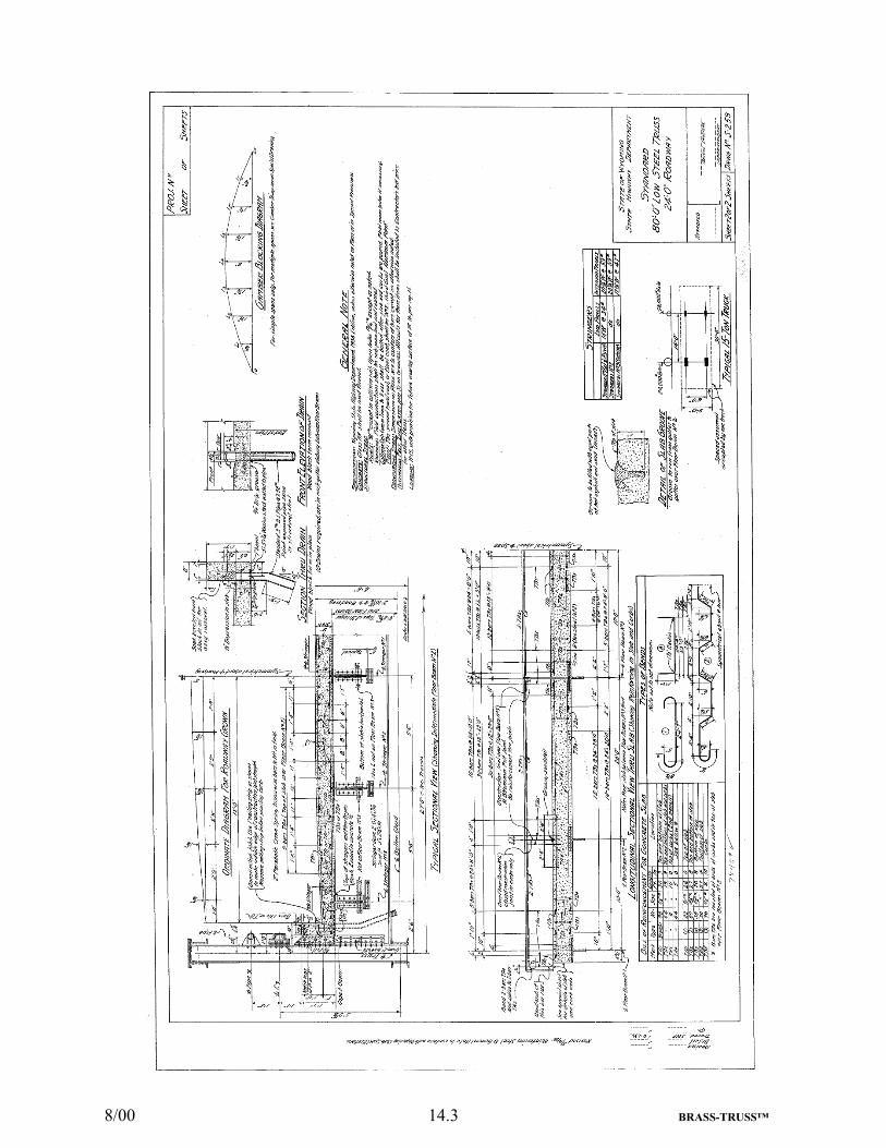
8/00 14.3 BRASS-TRUSS™

8/00 14.4 BRASS-TRUSS™