brake system overview - · pdf filebrake system overview ... side at the bulkhead. the...
TRANSCRIPT

Overview Brake System
BRAKE SYSTEMOVERVIEW
GENERAL
The brake system is a dual circuit, diagonally split system with disc brakes front and rear.
The power brake booster (servo) is single acting and has an integrated mechanical function forEmergency Brake Assist (EBA). The power brake booster is connected to the engine's intake manifoldand to a vacuum pump. Cars with gasoline engines have an electrical pump, while diesel engined carshave a mechanical pump.
The parking brake is mechanical with a lever and mechanical cables. The brakes act on the rearwheels via a mechanism integrated with the rear brake callipers.
BRAKE CONTROL SYSTEM
The brake control system is a Mark 60 with integrated ABS and EBD functions.
As an option, the system can be factory fitted with STC or DSTC.
Mark 60 is similar to the Mark 25 ABS system on the P2 platform, but is adapted for the smaller andlighter P1 platform.
WHEEL BRAKES
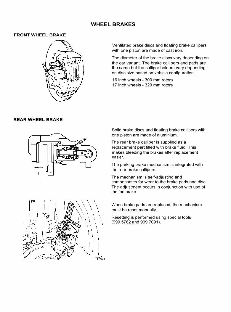
FRONT WHEEL BRAKE
Ventilated brake discs and floating brake calliperswith one piston are made of cast iron.
The diameter of the brake discs vary depending onthe car variant. The brake callipers and pads arethe same but the calliper holders vary dependingon disc size based on vehicle configuration.
16 inch wheels - 300 mm rotors17 inch wheels - 320 mm rotors
REAR WHEEL BRAKE
Solid brake discs and floating brake callipers withone piston are made of aluminium.
The rear brake calliper is supplied as areplacement part filled with brake fluid. Thismakes bleeding the brakes after replacementeasier.
The parking brake mechanism is integrated withthe rear brake callipers.
The mechanism is self-adjusting andcompensates for wear to the brake pads and disc.The adjustment occurs in conjunction with use ofthe footbrake.
When brake pads are replaced, the mechanismmust be reset manually.
Resetting is performed using special tools(999 5782 and 999 7091).

HYDRAULIC SYSTEM
The system has dual circuits and is splitdiagonally (X-split).
The primary circuit covers the first section of themaster cylinder and the right front and left rearbrakes.
The secondary circuit covers the second sectionof the master cylinder and the left front and rightrear brakes.
CIRCUITS
The brake fluid reservoir has two chambers, oneper brake circuit, and an integral level sensor.
The level sensor is attached to the CentralElectronic Module (CEM).
The brake warning lamp in the combinedinstrument panel (DIM) will light if the brake fluidlevel is too low.
The master cylinder is tandem type, with twopistons - one per circuit. There are check valvesin the pistons which close during braking andopen when the brakes are released.
1. Secondary circuit chamber2. Check valve in the secondary piston3. Secondary piston4. Primary circuit chamber5. Check valve in the primary piston6. Primary piston/push rod (one unit)
MASTER CYLINDER
BRAKE FLUID RESERVOIR

POWER BRAKE BOOSTER (SERVO)
The power brake booster islocated in the enginecompartment against thebulkhead.
The brake control module (BCM)with hydraulic unit is alwayslocated in the enginecompartment on the left-handside at the bulkhead.
The illustration displays the powerbrake booster in partial brakingposition, brake release.
The power brake booster (servo) is single acting (one membrane) and has an integrated mechanicalfunction for EBA (Emergency Brake Assist).
EBA GeneralEBA is activated when the driver presses the brake pedal sufficiently hard and fast. Full servo effect isapplied and the ABS function controls the brake effect depending on the circumstances.
NOTE: The values in the diagrams below are not specific to any one model. They are only used asexamples of differences between cars with and without EBA.
Braking characteristics with and withoutEBA1 = insufficient driver reaction2 = hesitant driver reaction3 =with EBA
Braking distance from 100 km/h with andwithout EBA1 = insufficient driver reaction2 = hesitant driver reaction3 =with EBA

A - MECHANICAL VERSION, COMPONENTS AND FUNCTION
Braking without emergency brake assistanceThe EBA unit is designed to be activated incertain conditions.
During normal braking these conditions are notmet and the EBA unit remains in 'passive' modeand the power brake booster functions as normal.

Braking with emergency brake assistanceI f the driver presses the brake pedal sufficientlyhard and fast, the ball sleeve (8) moves faster(further to the left in the illustration) than the guidehousing (7).
The spring (10) affects the locking sleeve (11)which depresses the balls (9) on the ball sleeveramp and locks them in this position.
The EBA unit is now activated.
When the EBA unit is activated, the brakepedal/push rod (4) are in principle disconnectedfrom the valve piston (5).
The driver can therefore depress the brake pedalwithout any more physical effort.
Releasing the brake after braking withemergency brake assistance
The driver controls the pressure reduction throughpedal movement.
Reduction occurs in the normal way, that is thevalve piston closes the valve (3) for atmosphericpressure and opens the vacuum valve (2).
The EBA unit remains in the activated positionduring pressure reduction.
Just before standby position is reached thelocking sleeve (11) comes into contact with themounting bracket (6). The locking sleeve ispushed back to its original position and the EBAunit is returned to 'passive' mode.
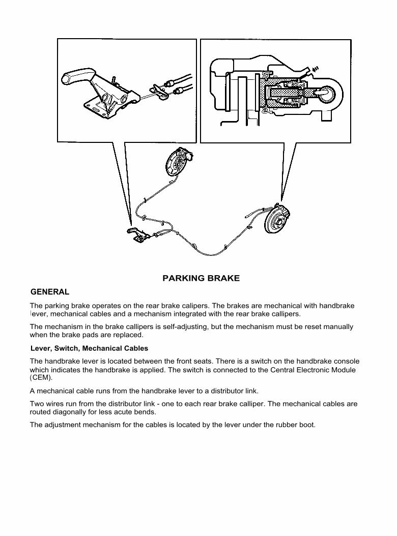
PARKING BRAKEGENERALThe parking brake operates on the rear brake calipers. The brakes are mechanical with handbrakelever, mechanical cables and a mechanism integrated with the rear brake callipers.
The mechanism in the brake callipers is self-adjusting, but the mechanism must be reset manuallywhen the brake pads are replaced.
Lever, Switch, Mechanical Cables
The handbrake lever is located between the front seats. There is a switch on the handbrake consolewhich indicates the handbrake is applied. The switch is connected to the Central Electronic Module(CEM).
A mechanical cable runs from the handbrake lever to a distributor link.
Two wires run from the distributor link - one to each rear brake calliper. The mechanical cables arerouted diagonally for less acute bends.
The adjustment mechanism for the cables is located by the lever under the rubber boot.

COMPONENTS AND FUNCTION
Applying the Parking BrakeThe parking brake cable pulls the lever (3). The movement is transferred via the eccentric (2) to thearm (1) which presses the adjuster screw (5). The force is transferred from the adjuster screw (5) viathe adjuster nut (8) to the brake calliper piston (10) and the brake pads are applied.
When the parking brake is released the components return to the resting position.Self-adjustmentAdjustment occurs when braking, using the footbrake.Adjustment is determined by the play in the threads between the adjuster screw (5) and the adjuster nut (8).
When the brake pedal is depressed the hydraulic pressure forces the brake piston out (10). Theadjuster nut (8) and the adjuster screw (5) follow this movement.
When the brake pedal is released the brake piston is pushed slightly back by the tension in the piston seal.
The adjuster nut (8) is pressed against the piston of the control spring (6), at the same time as thereturn spring (4) presses the adjuster screw (5) against the arm (1).
If the relative movement exceeds the play in the thread, the adjuster nut will be twisted to a newposition further out on the adjuster screw.
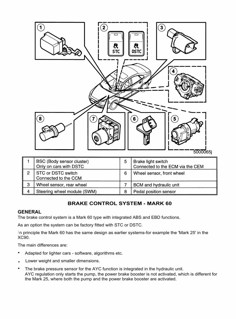
BRAKE CONTROL SYSTEM - MARK 60
GENERALThe brake control system is a Mark 60 type with integrated ABS and EBD functions.
As an option the system can be factory fitted with STC or DSTC.
I n principle the Mark 60 has the same design as earlier systems-for example the 'Mark 25' in theXC90.
The main differences are:
•
Adapted for lighter cars - software, algorithms etc.
•
Lower weight and smaller dimensions.
•
The brake pressure sensor for the AYC function is integrated in the hydraulic unit.AYC regulation only starts the pump, the power brake booster is not activated, which is different forthe Mark 25, where both the pump and the power brake booster are activated.

COMPONENTS
Brake Control Module (BCM) and Hydraulic UnitThe unit is located in the engine compartment on theleft-hand side against the bulkhead.
The control module processes the input signals andcontrols the hydraulic unit (pump and valves)depending on the prevailing driving conditions.
There are different versions of the control moduleand hydraulic unit depending on whether the car hasSTC/DSTC or not.
Control moduleThe control module has double micro processorswhich operate and perform calculations in parallel.
The control module for cars with ABS/EBD has 8valve coils for the hydraulic valves, 4 inlet and 4outlet valves.
Cars with STC and DSTC have an additional 4valve coils. Cars with DSTC also have anadditional terminal for the brake pressure sensor inthe hydraulic unit.
Note: On cars with DSTC the control module mustbe calibrated after replacement.
The illustration shows the control module for carswith STC.
Hydraulic UnitThe hydraulic unit contains:
•
Hydraulic valves - 8 for cars withoutSTC/DSTC and 12 for cars with STC/DSTC.
•
Accumulators and check valves.
•
Pump motor.•
Brake pressure sensor - only for cars withDSTC.
The hydraulic unit is supplied as a replacementpart filled with brake fluid. This makes it easier tobleed the system when the unit has beenreplaced.
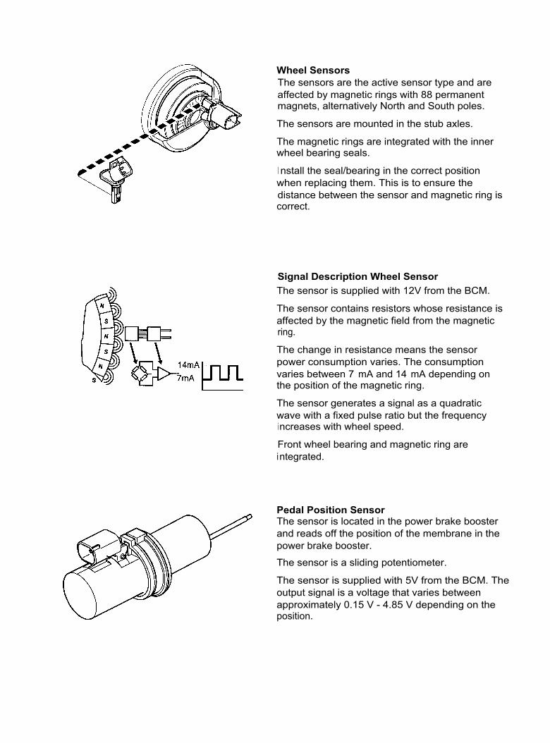
Wheel SensorsThe sensors are the active sensor type and areaffected by magnetic rings with 88 permanentmagnets, alternatively North and South poles.
The sensors are mounted in the stub axles.
The magnetic rings are integrated with the innerwheel bearing seals.
I nstall the seal/bearing in the correct positionwhen replacing them. This is to ensure thedistance between the sensor and magnetic ring iscorrect.
Signal Description Wheel SensorThe sensor is supplied with 12V from the BCM.
The sensor contains resistors whose resistance isaffected by the magnetic field from the magneticring.
The change in resistance means the sensorpower consumption varies. The consumptionvaries between 7 mA and 14 mA depending onthe position of the magnetic ring.
The sensor generates a signal as a quadraticwave with a fixed pulse ratio but the frequencyincreases with wheel speed.
Front wheel bearing and magnetic ring areintegrated.
Pedal Position SensorThe sensor is located in the power brake boosterand reads off the position of the membrane in thepower brake booster.
The sensor is a sliding potentiometer.
The sensor is supplied with 5V from the BCM. Theoutput signal is a voltage that varies betweenapproximately 0.15 V - 4.85 V depending on theposition.

Brake Light SwitchThe brake light switch is located by the brake pedallever. The switch is self-adjusting duringi nstallation.
The switch is open when the brake pedal isunaffected and closes when the brake pedal isdepressed.
The switch is supplied with 12 V via 30 V at theignition switch and the output signal is connectedto the ECM via the CEM.
The BCM receives information about the switchposition via the CAN.
Body Sensor Cluster (BSC)Cars with DSTC only
The sensor is positioned under the right front seat.
The sensor must be installed correctly to function.The BCM must be calibrated after replacing thesensor.The sensor contains:•
A sensor which measures the yaw angle of thecar in ° /s (yaw angle = the rotation of the cararound the vertical axis).
•
A sensor which measures the lateralacceleration of the car in m/s2 .
The sensor is a slave module for the BCM.Communication between the sensor and BCM isthrough an adapted CAN protocol.
Switch for STC or DSTCThe switch is located in the center consolebetween the front seats.
The STC/DSTC function is always activated whenthe ignition is switched on. This is indicated bythe LED on the button lighting.
The function can be reduced and reactivated bypressing the switch for at least half a second.
Reduction means the SC (stability function) isswitched off and the AYC enters 'Wideslip mode'.
This is indicated by the LED on the button goingout and the DIM displaying the system status.

SIGNAL SPECIFICATIONINPUT SIGNALS, DIRECTLY CONNECTED
INPUT SIGNALS VIA CAN COMMUNICATION

Brake System Signal Specification
INPUT SIGNALS VIA CAN COMMUNICATION
OUTPUT SIGNALS VIA CAN COMMUNICATION
81
Component InformationDIM (5/1) Vehicle speed.
Request to light the information lamp, warning lamps and display textmessage in the text window.
CCM (3/112) Request to light/switch off the LED in the switch for STC/DSTC.TCM (4/28) Vehicle speed.
Pedal position sensor position.Request to delay a gearshift in the event of excessive speeddifference between the front wheels.
ECM (4/46) Vehicle speed.Pedal position sensor position.Whether ABS, SC or TC control is active.Request for torque limiting during SC control.
I CM (16/1) For cars with RTI number of front wheel rotations and total distancetraveled.
Component I nformationCEM (4/56) Vehicle configuration.
Reverse gear engaged or not (manual transmission). This informationis used by the BCM to disable the AYC function when reverse gear isengaged.
TCM (4/28) Reverse gear engaged or not. This information is used by the BCM todisable the AYC function when reverse gear is engaged.Actual gear, next gear and lock-up status.
SWM (3/254)Cars with DSTC only
Steering wheel signal status - OK or not OK.Steering wheel position, at what speed the steering wheel is beingturned to the left or to the right.
ECM (4/46) Engine status engine running or not.Actual engine speed (RPM) and torque.Brake light switch status - closed or open.This information is used by the BCM to diagnose the brake pedalposition sensor function.
CCM (3/112) Switch position STC/DSTC full or reduced function.

ABS - CONTROL
ABS Control functions in the same way as other similar systems.
During control, the hydraulic pump runs and inlet/outlet valves switch between pressure increase,pressure maintenance and pressure dumping depending on the acceleration and deceleration of thewheels.
Some facts:
•
The brake force is controlled so the greatest possible brake force is transferred to the road surface.This occurs when the wheels rotate with 15 - 20 % slippage against the road surface.
•
The ABS function is only active at speeds above 7 km/h.At speeds below 7 km/h the wheels may lock, but this has no practical effect on driving stability orbraking distance.

EBD CONTROL
EBD Control functions in the same way as other similar systems.
During control, the inlet/outlet valves for the rear wheels switch between pressure increase, pressuremaintenance and pressure dumping depending on the acceleration and deceleration of the wheels. Thehydraulic pump does not start, the fluid volume returned from the rear wheel brakes is taken up by theaccumulators (A1-A2).
Some facts:
•
The brake effect is controlled so rear wheel slippage is less than the front wheel slippage.•
The rear wheels tendency to slippage is dependent on the pressure on the rear wheels - thepressure is affected by factors such as the load in the vehicle. The function is consequently loaddependent.

STC
Additional Components
For cars with STC the following components are added (1 per circuit):
STC Control
The STC function consists of two components:•
SC (Stability Control).•
TC (Traction Control).
SC Control
SC Control functions in the same way as other similar systems.During control the BCM transmits a request to the ECM to reduce engine torque.
Some facts:
•
SC functions between 0 km/h and top speed.
Traction Control
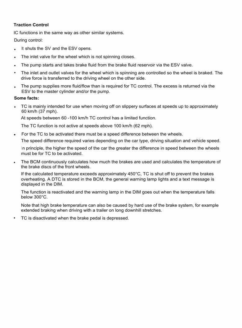
IC functions in the same way as other similar systems.
During control:
•
It shuts the SV and the ESV opens.
•
The inlet valve for the wheel which is not spinning closes.
•
The pump starts and takes brake fluid from the brake fluid reservoir via the ESV valve.
•
The inlet and outlet valves for the wheel which is spinning are controlled so the wheel is braked. Thedrive force is transferred to the driving wheel on the other side.
•
The pump supplies more fluid/flow than is required for TC control. The excess is returned via theESV to the master cylinder and/or the pump.
Some facts:
•
TC is mainly intended for use when moving off on slippery surfaces at speeds up to approximately60 km/h (37 mph).At speeds between 60 -100 km/h TC control has a limited function.
The TC function is not active at speeds above 100 km/h (62 mph).
•
For the TC to be activated there must be a speed difference between the wheels.The speed difference required varies depending on the car type, driving situation and vehicle speed.
In principle, the higher the speed of the car the greater the difference in speed between the wheelsmust be for TC to be activated.
•
The BCM continuously calculates how much the brakes are used and calculates the temperature ofthe brake discs of the front wheels.If the calculated temperature exceeds approximately 450°C, TC is shut off to prevent the brakesoverheating. A DTC is stored in the BCM, the general warning lamp lights and a text message isdisplayed in the DIM.
The function is reactivated and the warning lamp in the DIM goes out when the temperature fallsbelow 300°C.
Note that high brake temperature can also be caused by hard use of the brake system, for exampleextended braking when driving with a trailer on long downhill stretches.
•
TC is disactivated when the brake pedal is depressed.
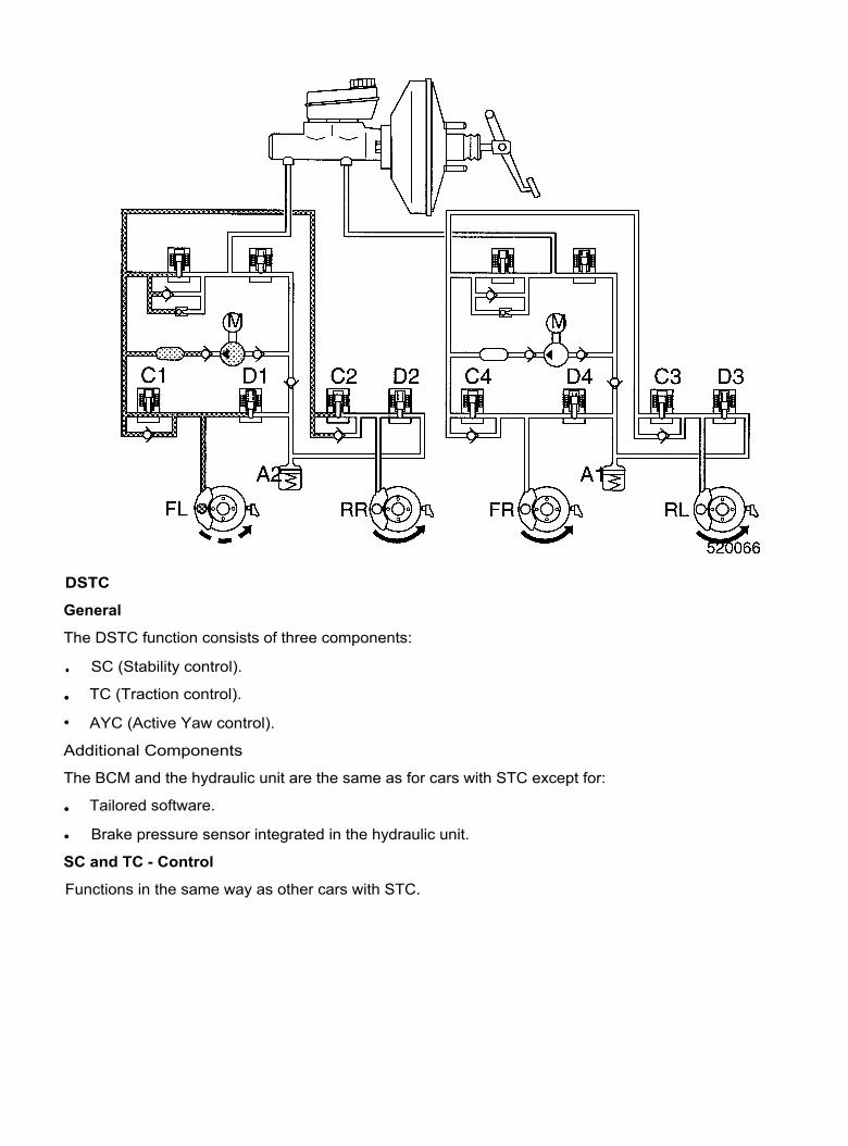
DSTC
General
The DSTC function consists of three components:
•
SC (Stability control).
•
TC (Traction control).
•
AYC (Active Yaw control).
Additional Components
The BCM and the hydraulic unit are the same as for cars with STC except for:
•
Tailored software.
•
Brake pressure sensor integrated in the hydraulic unit.
SC and TC - Control
Functions in the same way as other cars with STC.

Automatic Yaw Control
AYC control functions in the same way as other similar systems.
As on the S60, the hydraulic pump starts with AYC regulation, however the power brake booster is notactivated. It is not required because the S40/V50 is a lighter vehicle and pressure is built up by thepump sufficiently and quickly without help from the power brake booster.
The BCM continuously monitors:
•
Steering wheel angle, the speed at which the steering wheel is being turned (to the left or to theright).
• Engine torque.
• Vehicle speed.
•
The vehicle yaw rate and lateral acceleration.AYC is activated if the difference between the driver's intended direction and the behavior of the vehicleexceeds a certain limit.
First the BCM requests that the ECM adapt the engine torque and that the TCM adapt the gearshifts.
During the second stage, the brake system is activated by the BCM:
•
Shuts the SV and opens the ESV.
•
Starting the hydraulic pump (the brake pressure sensor in the hydraulic unit provides the BCM withinformation about the actual brake pressure).
•
Activating the inlet and outlet valves so the correct wheel is braked to counteract under oroversteer.
Some facts:
•
I f the driver presses the brake pedal during AYC, the BCM will use the pressure applied by thedriver in its calculations.
•
AYC function diminishes at low speeds. The function is not noticeable at or below speeds of6- 10 mph.

INFORMATION/WARNING LAMPS
The brake system uses five information/warning lamps and the DIM. The text displayed depends on theinformation/fault.
I n the event of a fault, the lamps light in different combinations depending on the fault. In certain cases atext message is also displayed in the DIM (Refer to table under Diagnostics on the next page).
No lamps are lit during normal function.
Note that the STC/DSTC lamp flashes during TC, SC and/or AYC control.
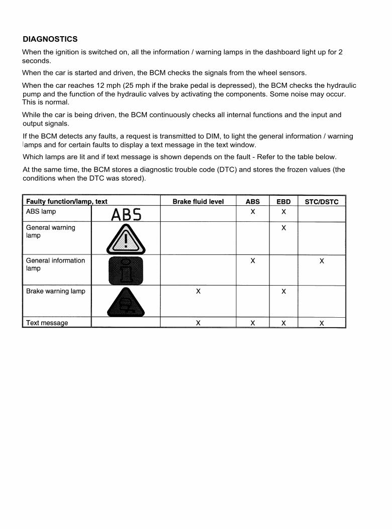
DIAGNOSTICSWhen the ignition is switched on, all the information / warning lamps in the dashboard light up for 2seconds.
When the car is started and driven, the BCM checks the signals from the wheel sensors.
When the car reaches 12 mph (25 mph if the brake pedal is depressed), the BCM checks the hydraulicpump and the function of the hydraulic valves by activating the components. Some noise may occur.This is normal.
While the car is being driven, the BCM continuously checks all internal functions and the input andoutput signals.
If the BCM detects any faults, a request is transmitted to DIM, to light the general information / warninglamps and for certain faults to display a text message in the text window.
Which lamps are lit and if text message is shown depends on the fault - Refer to the table below.
At the same time, the BCM stores a diagnostic trouble code (DTC) and stores the frozen values (theconditions when the DTC was stored).