bracket for sheet metal installation - … photovoltaic mounting systems assembly instructions...
TRANSCRIPT

1
Photovoltaic Mounting Systems
Assembly Instructions
© S:FLEX GmbH 09/2017 / design and engineering is subject to change
BRACKET FOR SHEET METAL INSTALLATIONMounting system for roofing with trapezoidal sheet metal

2
Index
S:FLEX GmbH Germany = Reinbeker Weg 9 21029 Hamburg Phone +49-(0)40-18 15 46 13 Fax +49-(0)40-18 15 46 14 [email protected] www.sflex.com
© S:FLEX GmbH 09/2017 / design and engineering is subject to change
1 Introduction
1.1 Intended use 3
1.2 About the document 3
1.3 Warnings 4
1.4 General information 4
1.5 Installation 5
1.6 Standards and guidelines 6
2 Installation – bracket for sheet metal installation
2.1 System components 7
2.2 Direct roof fastening using rivets/sheet metal screws 8
2.3 Installation – single layer substructure 9
2.4 Installation – double layer substructure 19

3S:FLEX GmbH Germany = Reinbeker Weg 9 21029 Hamburg Phone +49-(0)40-18 15 46 13 Fax +49-(0)40-18 15 46 14 [email protected] www.sflex.com
1 Introduction
© S:FLEX GmbH 09/2017 / design and engineering is subject to change
The S:FLEX PV mounting system for trapezoidal sheet roofs is a fastening system for the installation of PV modules. It is possible to both horizontally and vertically mount the modules using the S:FLEX mounting system. Both single layer installation and double layer installation are possible. Furthermore, both framed and frameless PV modules can be mounted.The S:FLEX PV mounting system for trapezoidal sheet roofs is characterised by a high degree of pre-assembly. The patented and proven click technology allows a maximum reduction in fitting times.All components are manufactured from aluminium and stainless steel. The high corrosion resistance guarantees a maximum lifespan and provides the possibility of complete recycling.
The S:FLEX PV mounting system for trapezoidal sheet roofs is a fastening system for the installation of PV modules. It is exclusively designed to accommodate PV modules.Any use that deviates from this must be regarded as not the intended use. In particular, the observation of the information in these installation guidelines counts as intended use. S:FLEX GmbH is not liable for damages that result from not observing the installation guidelines or from the improper and not intended use of the product.
1.2 About the document
The S:FLEX PV mounting system for trapezoidal sheet metal allows the installation of PV systems parallel to the roof. These installation guidelines describe the installation using brackets for sheet metal installation and mounting rails. This is possible for:
– Trapezoidal and corrugated sheet metal – Where applicable, sandwich profiles (if the manufacturer approves)
It is to be ensured that only the current and complete installation guidelines are used for the installation.
1.1 Intended use

4S:FLEX GmbH Germany = Reinbeker Weg 9 21029 Hamburg Phone +49-(0)40-18 15 46 13 Fax +49-(0)40-18 15 46 14 [email protected] www.sflex.com
1 Introduction
© S:FLEX GmbH 09/2017 / design and engineering is subject to change
1.3 Warnings
The warning notices used in these installation guidelines indicate safety related information.They are:
Failure to observe may lead to damage to property.
Severe risk of injury and danger to life if not observed.
1.4 General information
Before starting work on the roof, it must be verified that all currently valid accident prevention regulations are observed and that adequate protection is provided against falling parts (e.g. occupational health and safety regulations of the German national association of roofers (ZVDH)).
Before installation, the PV system maker must ensure that the existing roofing and roof substructure are suitable for the occurring additional loads. The condition of the roof substructure is to be examined by the maker (e.g. quality and strength of the purlins, if necessary the rafters and the roof battens, quality of the roofing, sufficient fastening of the roofing to the substructure, maximum load bearing capacity of the roofing).
Installation should only be carried out by skilled workers who work in accordance with the rules of the German national association of roofers (ZVDH).
Before the installation of the substructure, it must be verified that the module manufacturer’s specifications regarding module clamps (e.g. width and type of clamp, mounting guidelines for the clamp on the module) are observed. If this is not the case, the customer must obtain a declaration of consent from the module manufacturer before installation, or the frame must be adjusted according to the module manufacturer’s guidelines.
The requirements for the protection of PV mounting systems against lightning and surges are to be met in accordance with the DIN and VDE regulations (e.g. DIN EN 62305-1.4, DIN V VDE V 0100 Part 534, VdS guidelines 2010). The specifications of the relevant power supply company are to be observed.
During installation, fire protection regulations are to be observed, e.g. no firewalls are to be overbuilt.
If the roofing is altered, the manufacturer’s guidelines are to be observed. During and after the installation, the frame components may not be stepped on or be used as a climbing aid. There is a risk of falling and the roofing underneath it could be damaged.

5S:FLEX GmbH Germany = Reinbeker Weg 9 21029 Hamburg Phone +49-(0)40-18 15 46 13 Fax +49-(0)40-18 15 46 14 [email protected] www.sflex.com
1 Introduction
© S:FLEX GmbH 09/2017 / design and engineering is subject to change
1.5 Installation
The installation guidelines are for the installation of the S:FLEX PV mounting system on trapezoidal sheet roofs. The installation guidelines are intended for a group of people with relevant qualifications and who have been instructed by the operator of the PV system.
Please note: The installation should only be carried out by skilled workers who work in accordance with the rules of the German national association of roofers (ZVDH). System components (roof hooks, mounting rails) are not to be used as step ladders; the modules must not be stepped on.
When installing PV systems on roofs with corrugated metal roofing, the admissibility of the installation is to be ensured and, if necessary additional sealing measures in the area of the fastening to the roof membrane are to be implemented.

6S:FLEX GmbH Germany = Reinbeker Weg 9 21029 Hamburg Phone +49-(0)40-18 15 46 13 Fax +49-(0)40-18 15 46 14 [email protected] www.sflex.com
1 Introduction
© S:FLEX GmbH 09/2017 / design and engineering is subject to change
1.6 Standards and guidelines
These installation guidelines are based on current technology and many years of experience of how our systems can be installed on site. As individual project-related specifics must be considered for every roof, expert advice must always be sought before installation.Before installation, the maker of the photovoltaic system must ensure that the existing roof substructure is suitable for the occurring additional loads. To do this, contact structural engineers locally.Every photovoltaic system must be mounted in accordance with the structural requirements of the location and the installation situation while observing the specifications in these installation guidelines.
It must be ensured that only current and complete installation guidelines are used for the installation and that a printout of the installation guidelines is kept in the immediate vicinity of the system.
Subject to technical modifications.
While installing the PV system, the module manufacturer’s mounting instructions, the corresponding standards, accident prevention regulations as well as any further regulations and provisions must always be observed.
The documents listed in the following are information from S:FLEX GmbH and make no claim to be exhaustive. Every person who installs the S:FLEX PV mounting system has to independently inform themselves of all rules and guidelines for the technically correct planning and installation and observe them during the installation. This also includes obtaining the current version of the rules and guidelines.
BGV A2: Electrical systems and equipmentBGV C22: Construction workBGV D36: Ladders and step stoolsBGV A1: Accident prevention regulationsZVDH: Guidelines of the German national association of roofers (ZVDH)Eurocode 0 (DIN EN 1990): Basis of structural designEurocode 1 (DIN EN 1991): Actions on structuresEurocode 5 (DIN EN 1995): Design of timber structuresEurocode 9 (DIN EN 1999): Design of aluminium structures – Execution class according to Eurocode and EN 1090, Part 1 and 3: EXC 2DIN EN 1090-3: Execution of steel structures and aluminium structures – part of aluminium structuresDIN EN 62305-1-4: Protection against lightningDIN EN 62305-3: 2011 Protection against lightning Part 3: Physical damage to structures and life hazardDIN 18807-3: Trapezprofile im Hochbau, Stahltrapezprofile; Festigkeitsnachweis und Konstruktive AusbildungDIN 18807-9 Trapezoidal sheeting buildings, aluminium trapezoidal sheeting and their connections; application and construction DIN 18299 VOB Part C: General technical specifications in construction contracts (ATV) – General rules applying to all types of construction workDIN 18338 VOB Part C: General technical specifications in construction contracts (ATV) – Roofing workDIN 18451 VOB PartC: General technical specifications in construction contracts (ATV) – Scaffolding workDIN V VDE V 0100 Part 534: Devices for protection against overvoltageVDE 0100 - 712 ; IEC 64/1736: Low-voltage electrical installationsVDE 0185 Series, IEC 81/335: Protection against lightning

Seite 7 7S:FLEX GmbH Germany = Reinbeker Weg 9 21029 Hamburg Phone +49-(0)40-18 15 46 13 Fax +49-(0)40-18 15 46 14 [email protected] www.sflex.com
© S:FLEX GmbH 09/2017 / design and engineering is subject to change
2.1 System components
2 Installation – bracket for sheet metal installation
Components for roof fastenings1
Bracket for sheet metal installation complete
Slipping protection6 Slider locks7
Slider lock AK
Wood screws8
Slipping protection
Cross adapter clamps9
Cross adapter clamps
Splice3
Splice 5 Splice 26Splice 7 Splice 13
Mounting rails2
ST-AK 5/40 ST-AK 26/70ST-AK 7/47 ST-AK 13/60
End clamps4 Mid clamps5
EH AK II Klick 30-50 MH AK II Klick 30-50 A
EH AK II Klick 30-50 black MH AK II Klick 30-50 black
Covering caps10
Covering cap 5Covering cap 13Covering cap 7 Covering cap 26
Cable clips (optional)11
Cable straps edge clip KC 15

Seite 8 8S:FLEX GmbH Germany = Reinbeker Weg 9 21029 Hamburg Phone +49-(0)40-18 15 46 13 Fax +49-(0)40-18 15 46 14 [email protected] www.sflex.com
© S:FLEX GmbH 09/2017 / design and engineering is subject to change
2 Installation – bracket for sheet metal installation
When mounting the rivets or the sheet metal screws, the regulations stated in the approvals from the building authorities regarding the rivets/sheet metal screws are to be observed (e.g. area of application, pre-drill diameter, minimum strength of the materials to be fastened, hole diameter for existing holes). The corresponding rivets/sheet metal screws are part of our delivery. The selection of the fasteners depends on the roofing and the occurring forces. Rivets/sheet metal screws must only be positioned in the zone of the raised corrugations/ridges.
Sheet metal screw:4.5 x 25 (standard)6 x 25 (for trapezoidal sheet metal joints and tilt angle > 15°)Installation: SW 10Rivets:Blind rivet Polygrip Alu/Niro 4.8 x 12
2.2 Direct roof fastening using rivets/sheet metal screws
Seite 9 9S:FLEX GmbH Germany = Reinbeker Weg 9 21029 Hamburg Phone +49-(0)40-18 15 46 13 Fax +49-(0)40-18 15 46 14 [email protected] www.sflex.com
© S:FLEX GmbH 09/2017 / design and engineering is subject to change
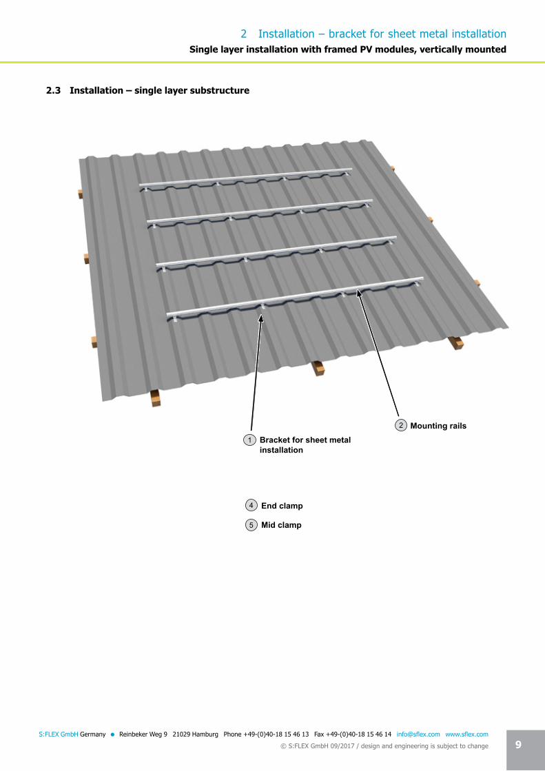
2.3 Installation – single layer substructure
2 Installation – bracket for sheet metal installationSingle layer installation with framed PV modules, vertically mounted
Bracket for sheet metal installation
1
Mounting rails2
Mid clamp5
End clamp4

Seite 10 10S:FLEX GmbH Germany = Reinbeker Weg 9 21029 Hamburg Phone +49-(0)40-18 15 46 13 Fax +49-(0)40-18 15 46 14 [email protected] www.sflex.com
© S:FLEX GmbH 09/2017 / design and engineering is subject to change
The positioning of the brackets for sheet metal installation must be determined according to the structural requirements of the location and the installation situation. In doing so, it must again be checked whether the measurements taken as a basis in the planning match the actual measurements found on the roof (if necessary, adjustments must be made). For single layer substructures, the position of the brackets for sheet metal installation must be checked against the module’s prescribed clamping distances.
Installation – 1 (positioning of the bracket for sheet metal installation, lower layer of rails)
Check the basis of the plans
Positioning according to the structural requirements and the installation situation
Align the brackets for sheet metal installation using plumb line
Mount the brackets for sheet metal installation complete with the correct fasteners (rivets/sheet metal screws). Use 2 rivets or 2 sheet metal screws per bracket. In the following figures, blind rivets are used. To avoid water penetration between the bracket and the roofing, the bracket for sheet metal installation must always be mounted on the raised corrugation/ridge. The bracket for sheet metal installation complete is pre-drilled with 2 x 5.0 mm holes and is extensively bonded with EPDM sealing tape on the underside.
Trapezoidal sheet metal2 rivets or 2 sheet metal screws per bracket.
2 Installation – bracket for sheet metal installationSingle layer installation with framed PV modules, vertically mounted

Seite 11 11S:FLEX GmbH Germany = Reinbeker Weg 9 21029 Hamburg Phone +49-(0)40-18 15 46 13 Fax +49-(0)40-18 15 46 14 [email protected] www.sflex.com
© S:FLEX GmbH 09/2017 / design and engineering is subject to change
2 Installation – bracket for sheet metal installation
Alignment of hammer-head bolt
Force-fit and form-fit connection
Check the alignment of the hammer-head bolts
Create a force-fit and form-fit connection
Use the adjustability due to the corrugation and elongated hole (21 mm)
Observe the orientation of the rails
10Position of hammer-head bolt
Mount the horizontally (parallel to the eaves) running mounting rails to the brackets using the hammer-head bolt M8x25 and the self-locking nut. Ensure the correct alignment of the hammer-head bolts in the mounting rail channel (torque 12-15 Nm) and that the mounting rails are mounted stress-free. To do this, use the adjustability that is created by the corrugation of the components and the elongated hole. Ensure that a force-fit and form-fit connection is created by interlocking the corrugations.For horizontally (parallel to the eaves) running mounting rails (lower rail layer), it is to be ensured that the brackets are always fixed to the underside of the rails (eaves side).
21 mm
Single layer installation with framed PV modules, vertically mounted

Seite 12 12S:FLEX GmbH Germany = Reinbeker Weg 9 21029 Hamburg Phone +49-(0)40-18 15 46 13 Fax +49-(0)40-18 15 46 14 [email protected] www.sflex.com
© S:FLEX GmbH 09/2017 / design and engineering is subject to change
2 Installation – bracket for sheet metal installation
In order to link several mounting rails, half of the splice, which has the same structural values as the mounting rails, is pushed into the already installed mounting rail. Then push the other mounting rail on to the splice. Use pressure to push the mounting rails flush together and check if a connection to earth has been created. The connection is finished. Fix the joined mounting rail on to the bracket as is described.
Installation – 2 (splice)
Push in splice
Check connection to earth
No cantilever arms with splices.Position the splices so that they lie between 2 brackets.
Cantilever arm
Push mounting rails together
Finished
Push in splice
Single layer installation with framed PV modules, vertically mounted

Seite 13 13S:FLEX GmbH Germany = Reinbeker Weg 9 21029 Hamburg Phone +49-(0)40-18 15 46 13 Fax +49-(0)40-18 15 46 14 [email protected] www.sflex.com
© S:FLEX GmbH 09/2017 / design and engineering is subject to change
2 Installation – bracket for sheet metal installation
Modules may not be built over expansion joints. There is no connection to earth. This must be established without limiting the expansion joint’s mode of operation.
Completion of the installation of the lower rail layer.
Expansion joint 2 cm
If the mounting rail is longer than 6.00 m, the module array is to be separated by placing two end clamps. In the zone between the end clamps, the mounting rail is to be separated and connected using a splice to allow the rail to move by 2 cm (expansion joint).The alignment of the expansion joints is to be adjusted according to the structural conditions of the roof and the different expansion properties of the materials. Observe the instructions in these installation guidelines when placing the end clamps.
Single layer installation with framed PV modules, vertically mounted

Seite 14 14S:FLEX GmbH Germany = Reinbeker Weg 9 21029 Hamburg Phone +49-(0)40-18 15 46 13 Fax +49-(0)40-18 15 46 14 [email protected] www.sflex.com
© S:FLEX GmbH 09/2017 / design and engineering is subject to change
2 Installation – bracket for sheet metal installation
Installation – 3 (module installation, slipping protection)
Before the installation of the modules in the lowest row of modules, the modules are generally to be furnished with the slipping protection. The same applies for modules under which no further module directly adjoins (modules above obstructions, e.g. windows, chimneys etc.).Fix 2 screws M6 x 20 (with the shank downward) with nuts M6 in 2 of the module’s frame holes (8 mm) so that the screws are at the same level and that when installed they are above at least one horizontal mounting rail layer, if necessary so that the screws on the underside of the module frame touch the horizontal mounting rails from above. If the lower fastening borehole is larger than 8 mm, please use a screw appropriate for this.
10
Single layer installation with framed PV modules, vertically mounted

Seite 15 15S:FLEX GmbH Germany = Reinbeker Weg 9 21029 Hamburg Phone +49-(0)40-18 15 46 13 Fax +49-(0)40-18 15 46 14 [email protected] www.sflex.com
© S:FLEX GmbH 09/2017 / design and engineering is subject to change
2 Installation – bracket for sheet metal installation
Installation – 4 (module installation, end clamp)
Mount end clamp
Check the end clamp has been clicked in
Both sides clicked INCORRECT Defined clamping area INCORRECT
Check the clamping area defined by the module manufacturer and observe the module manufacturer’s specifications
5
Click end clamp...
Place the module on the mounting rails. Mount the end clamps. To do this, click the end clamp on to the mounting rail and push it on to the module. It must be ensured that the end clamp is clicked into both sides of the mounting rail. Now adjust the end clamp to the height of the module and tighten the screw (torque 8-10 Nm). Ensure that the end clamp clamps the module frame at the clamping area defined by the module manufacturer.
... push in and screw tight
Single layer installation with framed PV modules, vertically mounted

Seite 16 16S:FLEX GmbH Germany = Reinbeker Weg 9 21029 Hamburg Phone +49-(0)40-18 15 46 13 Fax +49-(0)40-18 15 46 14 [email protected] www.sflex.com
© S:FLEX GmbH 09/2017 / design and engineering is subject to change
2 Installation – bracket for sheet metal installation
Installation – 5 (module installation, mid clamp)
Now mount the mid clamps. To do this, click the mid clamp on to the mounting rail and push it on to the module. It must be ensured that the mid clamp is clicked into both sides of the mounting rail.
Mount mid clamp
5
Single layer installation with framed PV modules, vertically mounted
Click mid clamp and push in
Push module under and screw mid clamp tight

Seite 17 17S:FLEX GmbH Germany = Reinbeker Weg 9 21029 Hamburg Phone +49-(0)40-18 15 46 13 Fax +49-(0)40-18 15 46 14 [email protected] www.sflex.com
© S:FLEX GmbH 09/2017 / design and engineering is subject to change
2 Installation – bracket for sheet metal installation
Ensure that the mid clamp clamps both module frames at the clamping area defined by the module manufacturer.
Check that the mid clamp has been clicked in
Check the defined clamping area and observe the module manufacturer’s specifications
Single layer installation with framed PV modules, vertically mounted
Both sides clicked
Defined clamping area INCORRECT
INCORRECT

Seite 18 18S:FLEX GmbH Germany = Reinbeker Weg 9 21029 Hamburg Phone +49-(0)40-18 15 46 13 Fax +49-(0)40-18 15 46 14 [email protected] www.sflex.com
© S:FLEX GmbH 09/2017 / design and engineering is subject to change
2 Installation – bracket for sheet metal installation
Installation – 6 (module installation, end clamp on row end)
On the last module in the row (if applicable, on expansion joints), end clamps are again to be mounted. To do this, click the end clamp on to the mounting rail and push it on to the module. It must be ensured that the end clamp is clicked into both sides of the mounting rail. Now adjust the end clamp to the height of the module and tighten the screw (torque 8-10 Nm).Ensure that the end clamp clamps the module frame at the clamping area defined by the module manufacturer (see Installation – 4).
Proceed as described for the following rows.
Mount end clamp on the last module. 5
Single layer installation with framed PV modules, vertically mounted

Seite 19 19S:FLEX GmbH Germany = Reinbeker Weg 9 21029 Hamburg Phone +49-(0)40-18 15 46 13 Fax +49-(0)40-18 15 46 14 [email protected] www.sflex.com
© S:FLEX GmbH 09/2017 / design and engineering is subject to change
2 Installation – bracket for sheet metal installation
2.4 Installation – double layer substructure
Double layer installation is particularly recommended for the installation of frameless modules with laminate clamps.Advantages: Height adjustment thanks to the lower rail layer – variable selection of the clamping area – slipping protection thanks to horizontal mounting.
Double layer installation with framed or frameless PV modules, horizontally mounted
Bracket for sheet metal installation1 Mounting rails2
Cross adapter clamp8
Splice3
Seite 20 20S:FLEX GmbH Germany = Reinbeker Weg 9 21029 Hamburg Phone +49-(0)40-18 15 46 13 Fax +49-(0)40-18 15 46 14 [email protected] www.sflex.com
© S:FLEX GmbH 09/2017 / design and engineering is subject to change
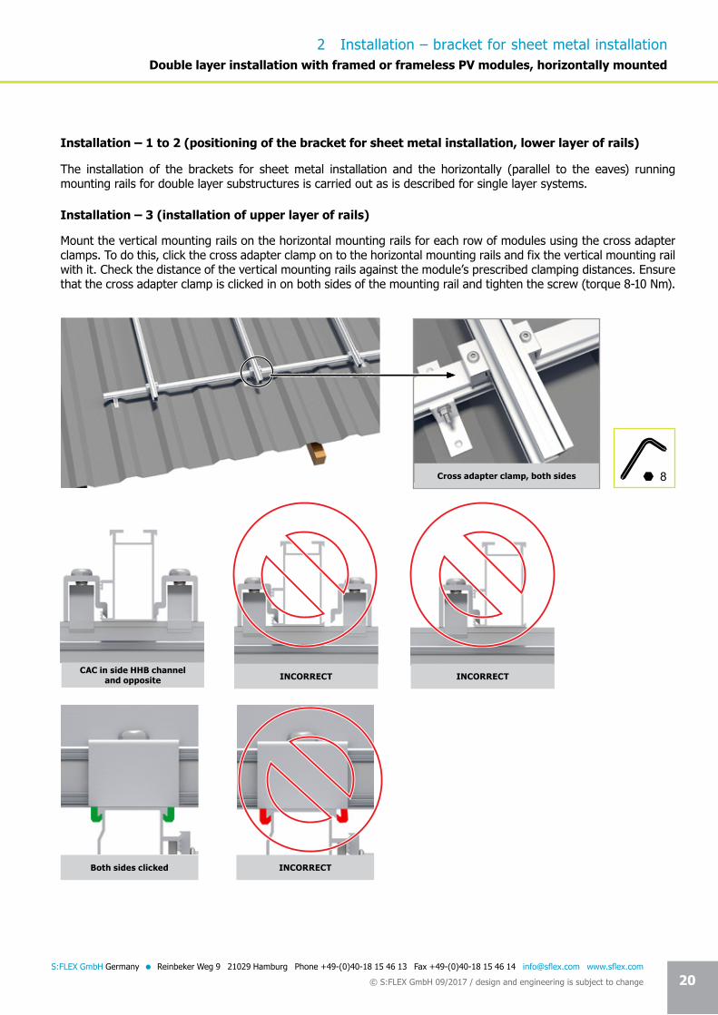
The installation of the brackets for sheet metal installation and the horizontally (parallel to the eaves) running mounting rails for double layer substructures is carried out as is described for single layer systems.
Mount the vertical mounting rails on the horizontal mounting rails for each row of modules using the cross adapter clamps. To do this, click the cross adapter clamp on to the horizontal mounting rails and fix the vertical mounting rail with it. Check the distance of the vertical mounting rails against the module’s prescribed clamping distances. Ensure that the cross adapter clamp is clicked in on both sides of the mounting rail and tighten the screw (torque 8-10 Nm).
Installation – 1 to 2 (positioning of the bracket for sheet metal installation, lower layer of rails)
Installation – 3 (installation of upper layer of rails)
8
INCORRECT
INCORRECT
Both sides clicked
Cross adapter clamp, both sides
CAC in side HHB channel and opposite INCORRECT
2 Installation – bracket for sheet metal installationDouble layer installation with framed or frameless PV modules, horizontally mounted

Seite 21 21S:FLEX GmbH Germany = Reinbeker Weg 9 21029 Hamburg Phone +49-(0)40-18 15 46 13 Fax +49-(0)40-18 15 46 14 [email protected] www.sflex.com
© S:FLEX GmbH 09/2017 / design and engineering is subject to change
2 Installation – bracket for sheet metal installation
Depending on the structural requirements of the location and the installation situation, several cross adapter clamps may be required per crossing point. If a second cross adapter clamp is required, it is fixed to the opposite side, as described above (torque 8-10 Nm).
Crossing points:
In order to link several mounting rails, half of the splice, which has the same structural values as the mounting rails, is pushed into the already installed mounting rail. Then push the other mounting rail on to the splice. Use pressure to push the mounting rails flush together and check if a connection to earth has been created. The connection is finished. Fix the joined mounting rail on to the horizontal mounting rail using a cross adapter clamp, as described in Installation – 4.
The vertical mounting rails are linked as is shown for horizontal mounting rails (see graphics Installation – 2).Position the splices so that they lie between 2 mounting rail crossing points (no cantilever arm with splices). When extending the vertical mounting rails on the lower eaves, it is to be ensured that the short mounting rail sections, which are connected underneath, run over at least 2 trapezoidal sheet metal rails. Check connection to earth.
Observe the module’s installation instructions for the distance between the vertical mounting rails.
Double layer installation with framed or frameless PV modules, horizontally mounted
ST-AK 5/40 ST-AK 7/47 ST-AK 13/60 ST-AK 26/70
1 CAC in side HHB channel 1 CAC in side HHB channel and 1 CAC opposite

Seite 22 22S:FLEX GmbH Germany = Reinbeker Weg 9 21029 Hamburg Phone +49-(0)40-18 15 46 13 Fax +49-(0)40-18 15 46 14 [email protected] www.sflex.com
© S:FLEX GmbH 09/2017 / design and engineering is subject to change
2 Installation – bracket for sheet metal installation
Modules may not be built over expansion joints.There is no connection to earth. This must be established without limiting the expansion joint’s mode of operation.
Completion of the installation of the upper rail layer.
Expansion joint 2 cm
Expansion joint – upper layer
If the mounting rail is longer than 6.00 m, the module array is to be separated by placing two end clamps. In the zone between the end clamps, the mounting rail is to be separated and connected using a splice to allow the rail to move by 2 cm (expansion joint).The alignment of the expansion joints is to be adjusted according to the structural conditions of the roof and the different expansion properties of the materials. Observe the instructions in Installation – 4 in these installation guidelines when placing the end clamps.
In the following, the column for column installation of the modules from top to bottom is described. The installation can also be carried out from bottom to top if the location requires it and the installation situation allows for it. The installation of frameless modules with laminate clamps should always be carried out from bottom to top. In the case of installation from bottom to top, a slider lock is to be pushed on to each lower mounting rail and tightened (torque 8-10 Nm) before the module installation.Ensure that all slider locks are fixed in a horizontal line.The end clamps are then clicked on to the mounting rails and pushed on to the slider locks.
Double layer installation with framed or frameless PV modules, horizontally mounted

Seite 23 23S:FLEX GmbH Germany = Reinbeker Weg 9 21029 Hamburg Phone +49-(0)40-18 15 46 13 Fax +49-(0)40-18 15 46 14 [email protected] www.sflex.com
© S:FLEX GmbH 09/2017 / design and engineering is subject to change
2 Installation – bracket for sheet metal installation
Installation – 4 (module installation, end clamp)
Place the module on the mounting rails. Mount the end clamps. To do this, click the end clamp on to the mounting rail and push it on to the module. It must be ensured that the end clamp is clicked into both sides of the mounting rail. Now adjust the end clamp to the height of the module and tighten the screw (torque 8-10 Nm). Ensure that the end clamp clamps the module frame at the clamping area defined by the module manufacturer.
Mount end clamp
Check the end clamp has been clicked in
Both sides clicked INCORRECT Defined clamping area INCORRECT
Check the clamping area defined by the module manufacturer and observe the module manufacturer’s specifications
5
Click end clamp...
... push in and screw tight
Double layer installation with framed or frameless PV modules, horizontally mounted
Seite 24 24S:FLEX GmbH Germany = Reinbeker Weg 9 21029 Hamburg Phone +49-(0)40-18 15 46 13 Fax +49-(0)40-18 15 46 14 [email protected] www.sflex.com
© S:FLEX GmbH 09/2017 / design and engineering is subject to change
2 Installation – bracket for sheet metal installation
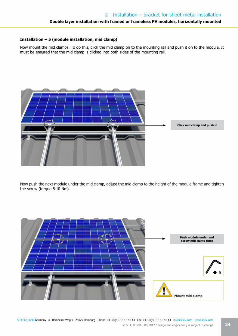
Installation – 5 (module installation, mid clamp)
Now mount the mid clamps. To do this, click the mid clamp on to the mounting rail and push it on to the module. It must be ensured that the mid clamp is clicked into both sides of the mounting rail.
Now push the next module under the mid clamp, adjust the mid clamp to the height of the module frame and tighten the screw (torque 8-10 Nm).
Mount mid clamp
5
Double layer installation with framed or frameless PV modules, horizontally mounted
Click mid clamp and push in
Push module under and screw mid clamp tight

Seite 25 25S:FLEX GmbH Germany = Reinbeker Weg 9 21029 Hamburg Phone +49-(0)40-18 15 46 13 Fax +49-(0)40-18 15 46 14 [email protected] www.sflex.com
© S:FLEX GmbH 09/2017 / design and engineering is subject to change
2 Installation – bracket for sheet metal installation
Ensure that the mid clamp clamps both module frames at the clamping area defined by the module manufacturer.
Check that the mid clamp has been clicked in
Check the clamping area defined by the module manufacturer and observe the module manufacturer’s specifications
Double layer installation with framed or frameless PV modules, horizontally mounted
Both sides clicked
Defined clamping area INCORRECT
INCORRECT

Seite 26 26S:FLEX GmbH Germany = Reinbeker Weg 9 21029 Hamburg Phone +49-(0)40-18 15 46 13 Fax +49-(0)40-18 15 46 14 [email protected] www.sflex.com
© S:FLEX GmbH 09/2017 / design and engineering is subject to change
Laminate end clamp (LEK)
Laminate mid clamp (LMK)
Clam
ping
are
a
The installation of frameless PV modules (laminates) is made possible by using perfectly fitting, certified laminate end clamps and laminate mid clamps. They are available either with the patented and proven click technology or with hammer-head bolts. Depending on the specifications of the laminate, different clamping areas and lengths are available.
Laminate clamps
Clam
ping
are
a
Clam
ping
are
a
51 m
m
80 mm
Maximum clamping area LMK:A=13.7*80=1096 mm² (per side, above and below)
37 m
m
13.7
mm
80 mm
Maximum clamping area LEK:A=13.7*80=1096 mm² (above and below)
You can find detailed information about the laminate end and laminate mid clamps in our technical documentation.
The module manufacturer must approve the use of the laminate end clamps and the laminate mid clamps (certification). You can receive an overview of the approvals from S:FLEX GmbH.
13.7
mm
13.7
mm
2 Installation – bracket for sheet metal installationDouble layer installation with framed or frameless PV modules, horizontally mounted
Seite 27 27S:FLEX GmbH Germany = Reinbeker Weg 9 21029 Hamburg Phone +49-(0)40-18 15 46 13 Fax +49-(0)40-18 15 46 14 [email protected] www.sflex.com
© S:FLEX GmbH 09/2017 / design and engineering is subject to change
2 Installation – bracket for sheet metal installation
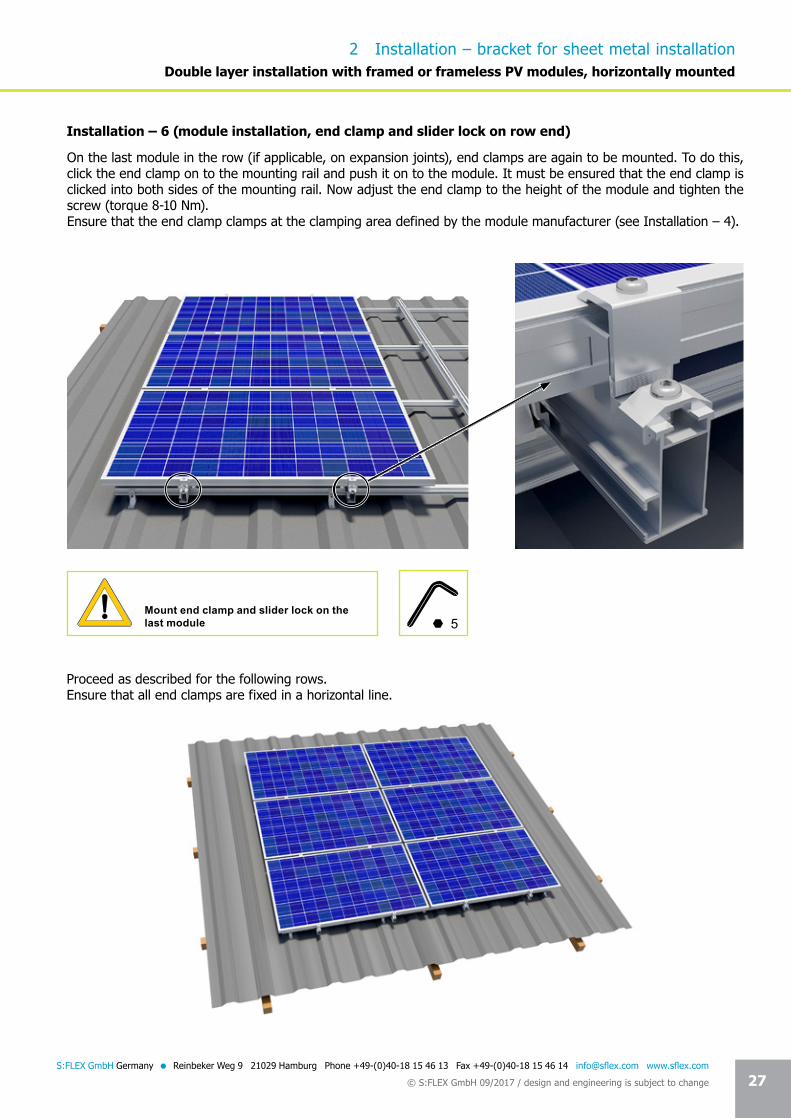
Installation – 6 (module installation, end clamp and slider lock on row end)
On the last module in the row (if applicable, on expansion joints), end clamps are again to be mounted. To do this, click the end clamp on to the mounting rail and push it on to the module. It must be ensured that the end clamp is clicked into both sides of the mounting rail. Now adjust the end clamp to the height of the module and tighten the screw (torque 8-10 Nm).Ensure that the end clamp clamps at the clamping area defined by the module manufacturer (see Installation – 4).
Mount end clamp and slider lock on the last module
Proceed as described for the following rows.Ensure that all end clamps are fixed in a horizontal line.
5
Double layer installation with framed or frameless PV modules, horizontally mounted