bracing alternatives in tapered frames under wind loads abstract
TRANSCRIPT
1
BRACING ALTERNATIVES IN TAPERED FRAMES UNDERWIND LOADS
Ing. Mic. Antonio María Merlano Rivera1,2
1Professor of Civil Engineering. Universidad Tecnológica de Bolívar, Cartagena, Colombia.2President of Antonio María Merlano y Cía. Ltda. Ingenieros Estructurales, Cartagena,
Colombia, [email protected]
ABSTRACTThe level of risk caused by forces of the nature could be reduced with an appropriateintervention of vulnerability, since such threats cannot be reduced. One of the alternatives toreduce the structural vulnerability of buildings is provide elements, such as bracing, to improvetheir behavior when they are subjected to forces arising from these threats. The reduction ofvulnerability in buildings type warehouse is achieved with elements that help to absorbhorizontal forces acting on it, such as bracing and wind bracing. Due to the limited informationabout the better way to distribute these elements to reach a good configuration of the structure,we present this document, where we will analyze different distributions for the bracing thatprovides the best cost-benefit.
INTRODUCTIONWhen a structure is being designed, in addition to their aesthetic part, some issues must be takeninto account such as security, functionality and economy. The aim of any project is likely toacceptable for the work is not considered inappropriate to their destination within a given period.Thus seeks to minimize the maximum possible faults that may occur when it is subjected toexternal forces that may threaten its stability.
Consequently, all structures must be designed and calculated to withstand, with anappropriate degree of security, to behave in a satisfactory manner during normal use. Onealternative to improve the structural behavior of a building is its bracing, which aims to provideelements that offer more resistance to this, especially when the building is subjected toconsiderable loads.
The system of steel tapered frames is currently being used to support the loads acting onthe structure, without using the traditional system of trusses, but like other systems, requireselements such as stiffeners and wind bracings to help absorb the forces acting on the building.
The limited information about how these elements should be distributed to achieveoptimal performance often affects the cost and misuse of these. Therefore, the importance of thiswork, aims to optimize the use of the stiffeners in order to get the best cost - benefit.
IMPORTANCE OF RESEARCHDetermine the effect of economic and structural safety of the number, distribution or position ofstiffeners and wind bracing for tapered warehouses with different spans in their cross sectionwhen wind loads are acting, using as example the city of Cartagena (Colombia), and anywhere inthe world where the forces of wind are considerably higher.
2
METODOLOGY
PROJECT DESCRIPTION AND REGULATIONS.The analysis and structural design was carried out according to the codes AISC - ASD 1989,ASCE-02 and approved by the NSR-98 (Standards of Colombian Earthquake Resistant Design -1998). We have studied models of structures that represent the most common warehouses thatare built in our country, as follows:
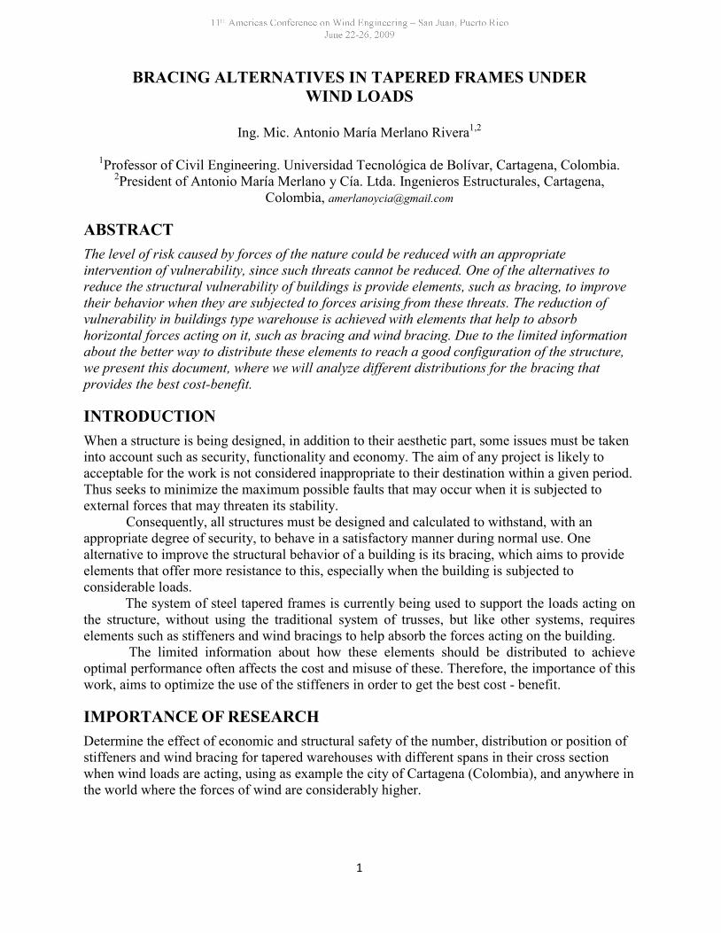
1. We have considered two (2) different models. For each of them we have analyzed four (4)types of warehouses, with spans 6, 9 and 12 meters between their cross frames. These modelare described below:
Model A. The characteristics of this model were: tapered frames and articulatedsupports. The first and last frames have articulated cross-beams and the columnsare equally articulated in the beams (See Figure 1).
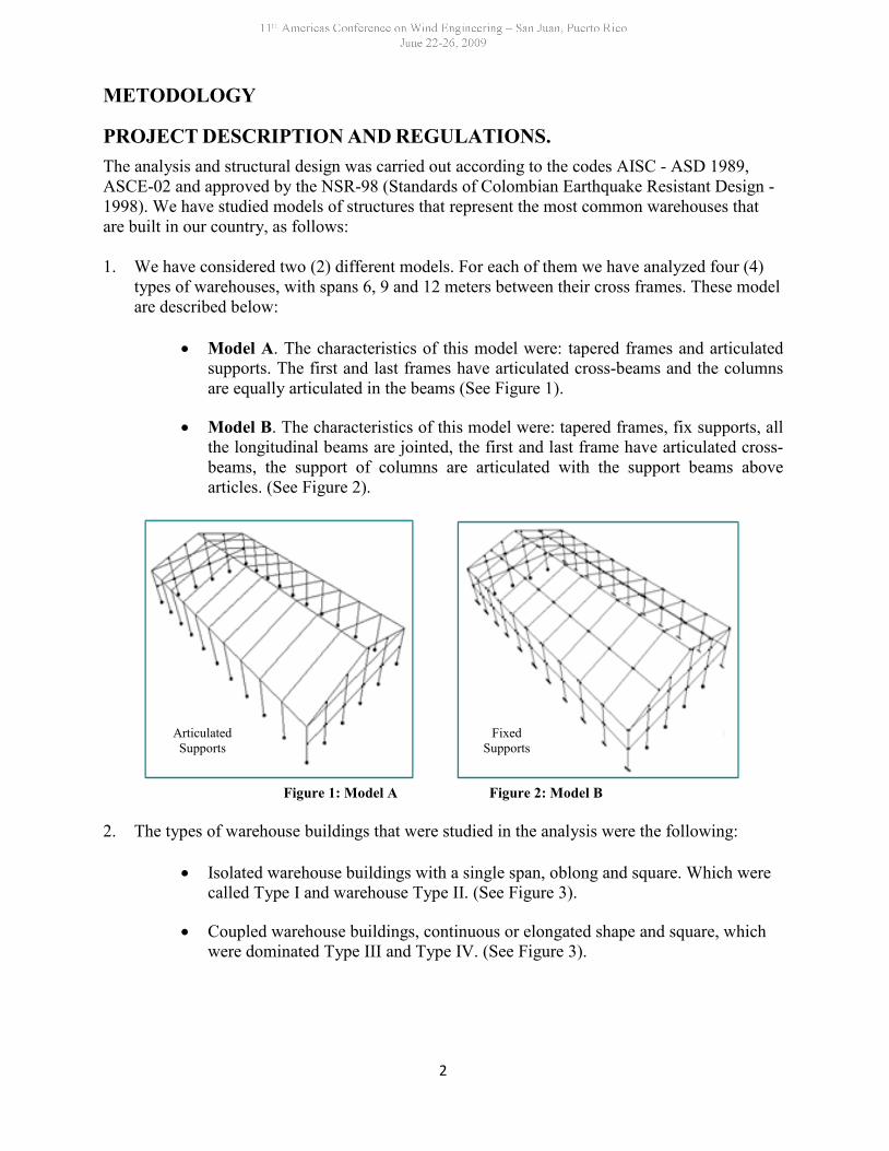
Model B. The characteristics of this model were: tapered frames, fix supports, allthe longitudinal beams are jointed, the first and last frame have articulated cross-beams, the support of columns are articulated with the support beams abovearticles. (See Figure 2).
Figure 1: Model A Figure 2: Model B
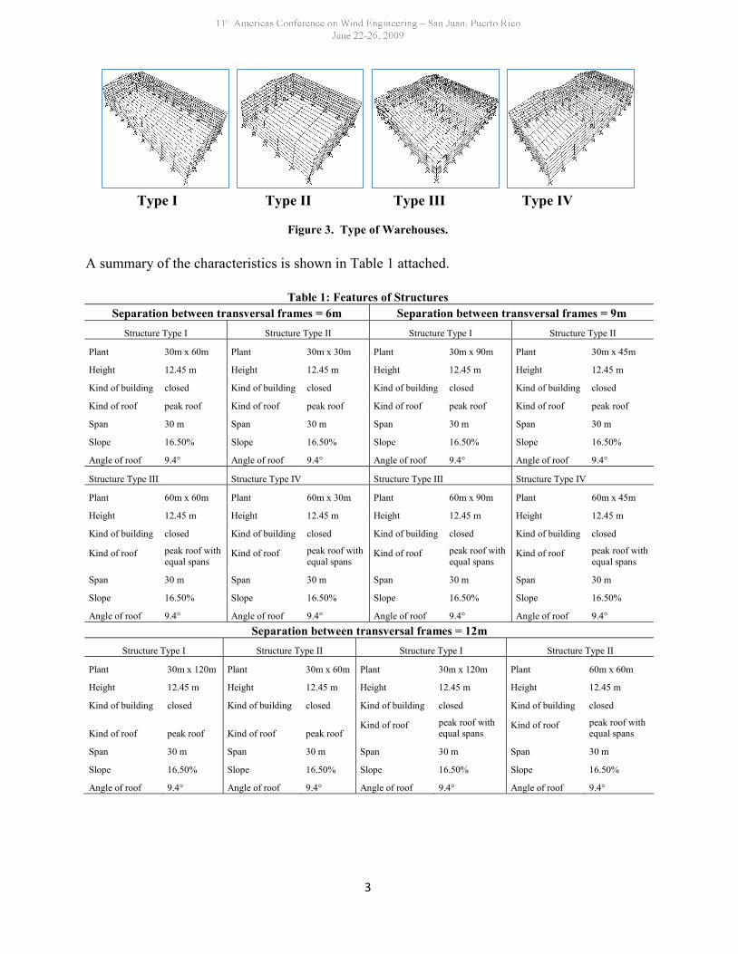
2. The types of warehouse buildings that were studied in the analysis were the following:
Isolated warehouse buildings with a single span, oblong and square. Which werecalled Type I and warehouse Type II. (See Figure 3).
Coupled warehouse buildings, continuous or elongated shape and square, whichwere dominated Type III and Type IV. (See Figure 3).
ArticulatedSupports
FixedSupports
3
Type I Type II Type III Type IV
Figure 3. Type of Warehouses.
A summary of the characteristics is shown in Table 1 attached.
Table 1: Features of StructuresSeparation between transversal frames = 6m Separation between transversal frames = 9m
Structure Type I Structure Type II Structure Type I Structure Type II
Plant 30m x 60m Plant 30m x 30m Plant 30m x 90m Plant 30m x 45m
Height 12.45 m Height 12.45 m Height 12.45 m Height 12.45 m
Kind of building closed Kind of building closed Kind of building closed Kind of building closed
Kind of roof peak roof Kind of roof peak roof Kind of roof peak roof Kind of roof peak roof
Span 30 m Span 30 m Span 30 m Span 30 m
Slope 16.50% Slope 16.50% Slope 16.50% Slope 16.50%
Angle of roof 9.4° Angle of roof 9.4° Angle of roof 9.4° Angle of roof 9.4°
Structure Type III Structure Type IV Structure Type III Structure Type IV
Plant 60m x 60m Plant 60m x 30m Plant 60m x 90m Plant 60m x 45m
Height 12.45 m Height 12.45 m Height 12.45 m Height 12.45 m
Kind of building closed Kind of building closed Kind of building closed Kind of building closed
Kind of roof peak roof withequal spans
Kind of roof peak roof withequal spans
Kind of roof peak roof withequal spans
Kind of roof peak roof withequal spans
Span 30 m Span 30 m Span 30 m Span 30 m
Slope 16.50% Slope 16.50% Slope 16.50% Slope 16.50%
Angle of roof 9.4° Angle of roof 9.4° Angle of roof 9.4° Angle of roof 9.4°Separation between transversal frames = 12m
Structure Type I Structure Type II Structure Type I Structure Type II
Plant 30m x 120m Plant 30m x 60m Plant 30m x 120m Plant 60m x 60m
Height 12.45 m Height 12.45 m Height 12.45 m Height 12.45 m
Kind of building closed Kind of building closed Kind of building closed Kind of building closed
Kind of roof peak roof Kind of roof peak roofKind of roof peak roof with
equal spansKind of roof peak roof with
equal spans
Span 30 m Span 30 m Span 30 m Span 30 m
Slope 16.50% Slope 16.50% Slope 16.50% Slope 16.50%
Angle of roof 9.4° Angle of roof 9.4° Angle of roof 9.4° Angle of roof 9.4°
4
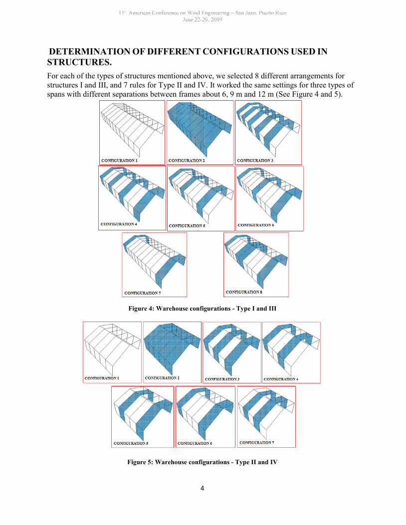
DETERMINATION OF DIFFERENT CONFIGURATIONS USED INSTRUCTURES.For each of the types of structures mentioned above, we selected 8 different arrangements forstructures I and III, and 7 rules for Type II and IV. It worked the same settings for three types ofspans with different separations between frames about 6, 9 m and 12 m (See Figure 4 and 5).
Figure 4: Warehouse configurations - Type I and III
Figure 5: Warehouse configurations - Type II and IV
5
FEATURES OF THE STRUCTURES. Basic Wind Speed. The project took the city of Cartagena (Colombia) with a basic
wind speed, V = 130 km / h.
Ratio of Surveying. It was taken a mapping coefficient S1 = 1.0, for all structuresstudied.
Roughness coefficient of the surface, size of the building ad height over ground.
Coefficient S2 = 0.87 (interpolated). For structures Type I, III and IV, with ClassC (since it has a dimension greater than 50 m) and a roughness of 2.
Coefficient S2 = 0.914 (interpolated). For the structure Type II, class B (since thedimensions do not exceed 50 m) and a roughness of 2.
Coefficient S3 (It was taken into account the level of safety and service life ofstructure). S3 = 1.0 was taken for all structures studied.
Coefficient S4 (consider the change in air density with height above sea level). S4= 1.0 was taken for all structures studied.
LOAD ANALYSISThe load cases considered for analysis were
Dead load: This load is shown in the Table 2
Table 2: Analysis of Dead LoadWeight of tapered frames **
Weight of straps **Weight of tile (Thermoacustic Ajover) 4.2 kg/m²
Lighting systems and others 10 kg/m²** Self weight was evaluated by the program SAP 2000
Live Load: To select this load, was taken into account the specification of steel structures andStandards of Colombian Earthquake Resistant Design NSR 98 . The Table 3 shows the live loadon the deck of the roof taken by numeral B.4.2.1 (NSR 98).
Table 3: Analysis of Live LoadType of roof Slope Load ( Kg/m² )
Steel sloping roof < 20% 50
6
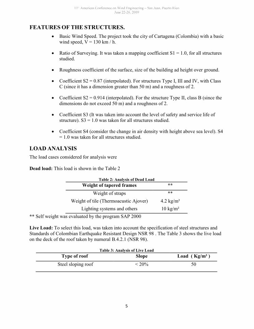
Wind Loads. Wind loads were calculated according to the methodology described in Part B,paragraph B.6.4.3, detailed analysis of the NSR 98 and ASCE-02 (Article 6.5). Because thepressure acting on the walls of structures increases in parabolic shape in all its height, is assumedas follows (See Figure 6).
Figure 6: Variation due to wind pressure on the walls
CONCLUSIONSIn order to determinate both economic and structural impact of the number and distribution ofbracing and wind bracing, each warehouse with their respective type of bracing alternatives weresubjected to the following analysis.
TECHNICAL ANALYSIS. The models were initially analyzed without any kind of bracing.The structural behavior under this configuration is inadequate to lateral load when the wind hits90 °, since high displacement were introduced in most cases, it suggests that we should putbracings and wind bracings because the roof an ridges does not provide sufficient rigidity to thesystem and, because of the rigid tapered frames may fail under the action of very small lateralforces.
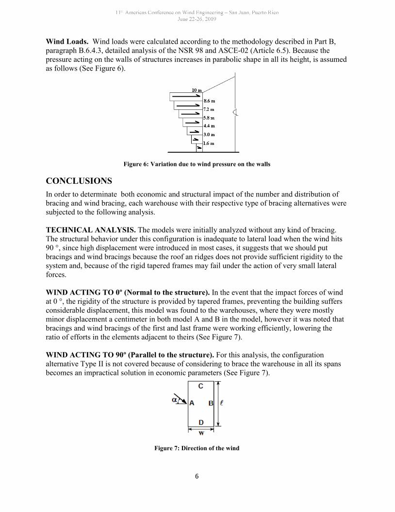
WIND ACTING TO 0º (Normal to the structure). In the event that the impact forces of windat 0 °, the rigidity of the structure is provided by tapered frames, preventing the building suffersconsiderable displacement, this model was found to the warehouses, where they were mostlyminor displacement a centimeter in both model A and B in the model, however it was noted thatbracings and wind bracings of the first and last frame were working efficiently, lowering theratio of efforts in the elements adjacent to theirs (See Figure 7).
WIND ACTING TO 90º (Parallel to the structure). For this analysis, the configurationalternative Type II is not covered because of considering to brace the warehouse in all its spansbecomes an impractical solution in economic parameters (See Figure 7).
Figure 7: Direction of the wind
7
ECONOMICAL ANALYSIS. The bracings are elements that work only under stress load. Theway they get lateral load and bring it to the foundation depends on the type of bracing youchoose. Their implementations are subjected to requirements about functionality as well aseconomic parameters. The structural engineer must find that these two variables are presentedsimultaneously in the design, it is not an easy task, but you can achieve configurations thatsatisfy some desires ensuring security supported by the standard. (NSR-98 and AISC-ASD).
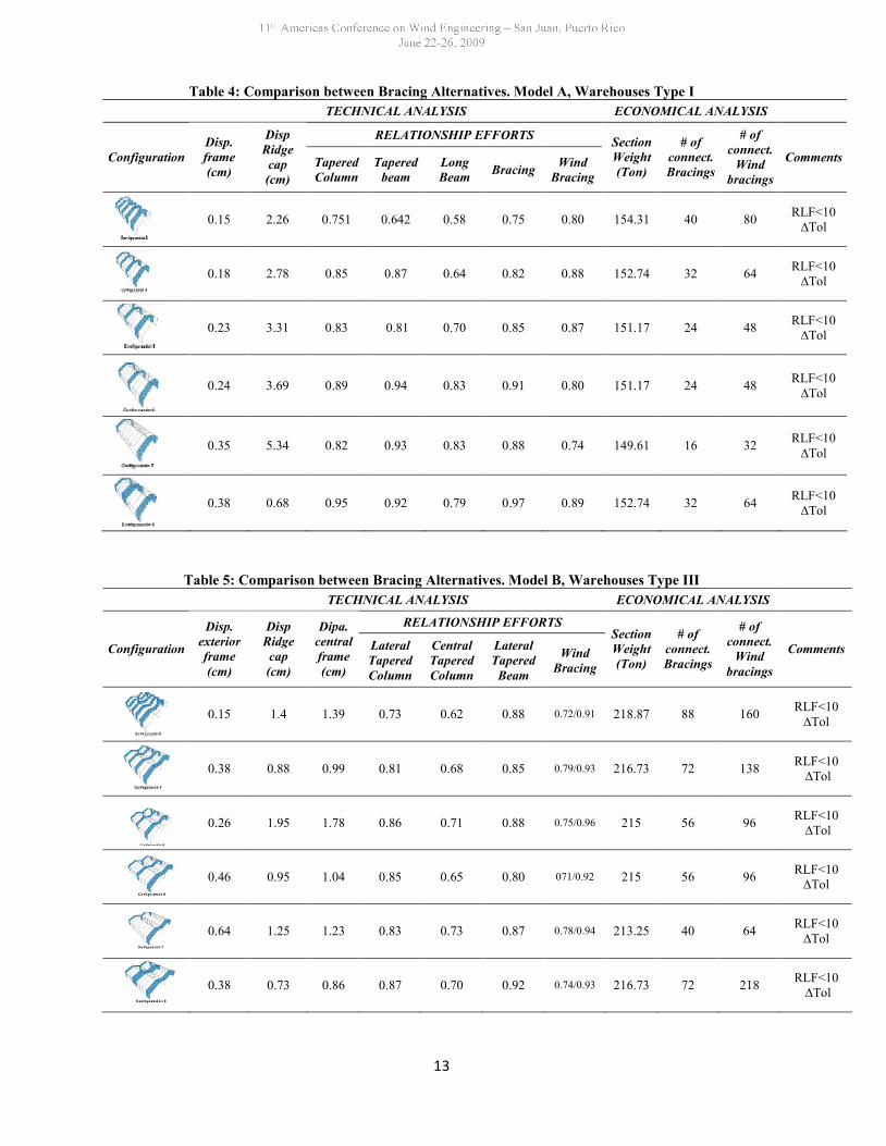
The greatest difficulty was found in the technical deficiency of the drift floor. When awarehouse is being designed, is not possible to find a limiting value of lateral movement (drift)with which one can say whether or not it satisfies with the standard. Since this parameter is tostudy the individual engineer and the considerations that set this in their models. The explainedbefore no occurs in a conventional building. For economic analysis, It was taken the total weightof the structure for each configuration. Some cases are shown in the Tables 4 and 5.
OPTIMAL CONFIGURATION. In several cases there were minor displacementconfigurations than those obtained with the configurations described above, however, taking intoaccount that bracings in the first and last span is crucial to stabilize the walls of the adjacentframe to these when the wind is normal the structure (angle 0 °). Longer warehouses need tobrace in central frame as this helps to give greater stability to the structure in the presence offorces of wind, reducing both the displacement and slope at ridge (See Tables 4 and 5).
Of the two models studied, it was found that the model B (with fix supports) gave betterresults, lower sections of profiles, and lower weight of the structure and movements in relationto low Model A. However one of the disadvantages of this model is that its supports areembedded, necessary condition for articulating joints of the longitudinal beams to the frames,and ensure the condition of the device support is difficult to achieve, without mentioning thatthese are more expensive than articulated. Regarding the spacing between transverse frames, itwas found that:
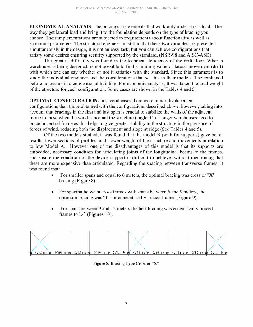
For smaller spans and equal to 6 meters, the optimal bracing was cross or "X"bracing (Figure 8).
For spacing between cross frames with spans between 6 and 9 meters, theoptimum bracing was “K” or concentrically braced frames (Figure 9).
For spans between 9 and 12 meters the best bracing was eccentrically bracedframes to L/3 (Figures 10).
Figure 8: Bracing Type Cross or “X”
8
Figure 9: Bracing Type K or concentrically braced frames
Figure 10: Eccentrically braced frames to L/3
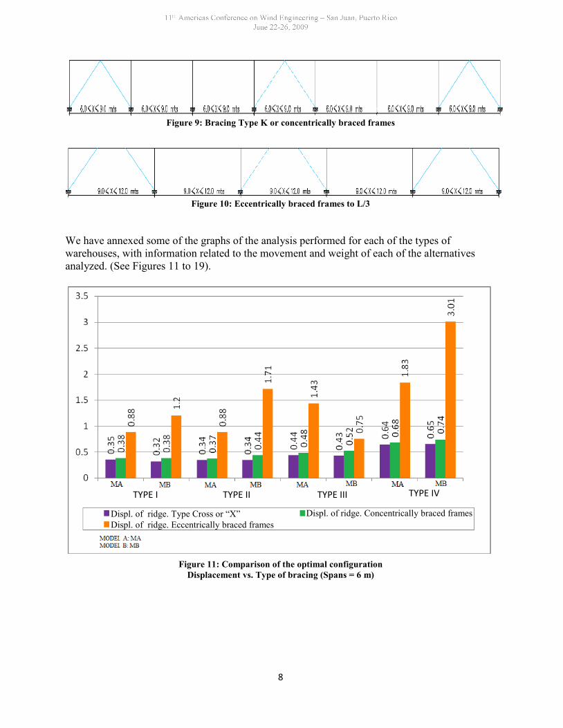
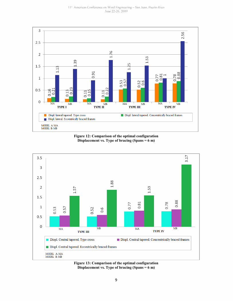
We have annexed some of the graphs of the analysis performed for each of the types ofwarehouses, with information related to the movement and weight of each of the alternativesanalyzed. (See Figures 11 to 19).
Figure 11: Comparison of the optimal configurationDisplacement vs. Type of bracing (Spans = 6 m)
TYPE IITYPE I TYPE III TYPE IV
Displ. of ridge. Type Cross or “X” Displ. of ridge. Concentrically braced framesDispl. of ridge. Eccentrically braced frames
9
Figure 12: Comparison of the optimal configurationDisplacement vs. Type of bracing (Spans = 6 m)
Figure 13: Comparison of the optimal configurationDisplacement vs. Type of bracing (Spans = 6 m)
10
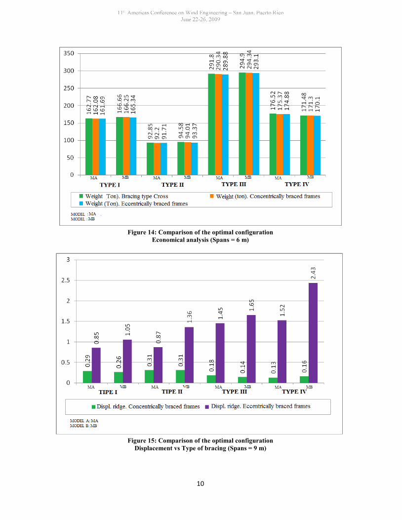
Figure 14: Comparison of the optimal configurationEconomical analysis (Spans = 6 m)
Figure 15: Comparison of the optimal configurationDisplacement vs Type of bracing (Spans = 9 m)
11
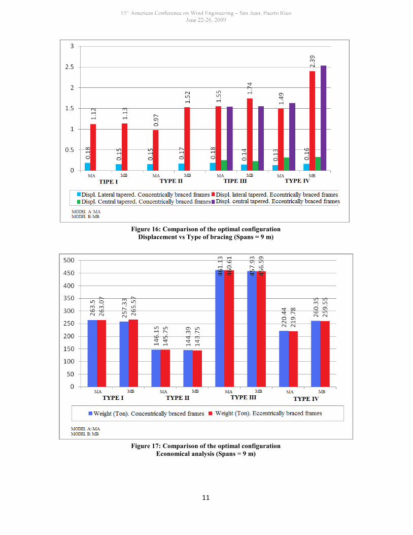
Figure 16: Comparison of the optimal configurationDisplacement vs Type of bracing (Spans = 9 m)
Figure 17: Comparison of the optimal configurationEconomical analysis (Spans = 9 m)
12
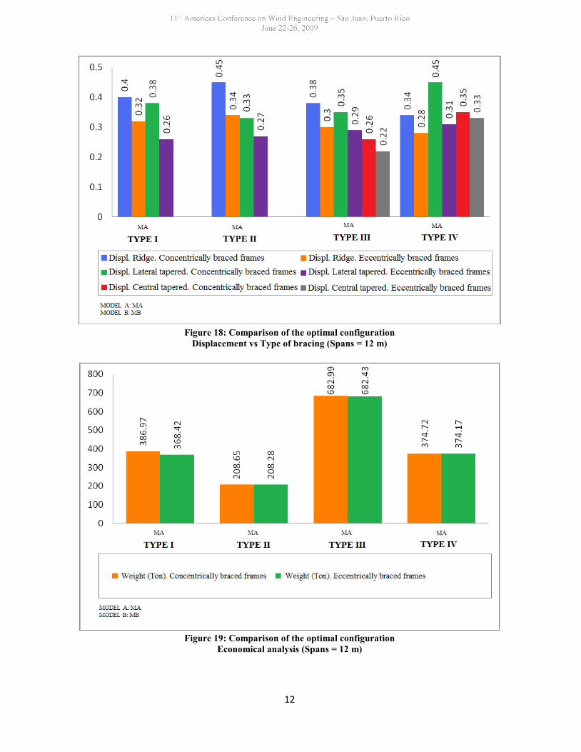
Figure 18: Comparison of the optimal configurationDisplacement vs Type of bracing (Spans = 12 m)
Figure 19: Comparison of the optimal configurationEconomical analysis (Spans = 12 m)
13
Table 4: Comparison between Bracing Alternatives. Model A, Warehouses Type ITECHNICAL ANALYSIS ECONOMICAL ANALYSIS
RELATIONSHIP EFFORTS
ConfigurationDisp.frame(cm)
DispRidgecap(cm)
TaperedColumn
Taperedbeam
LongBeam Bracing Wind
Bracing
SectionWeight(Ton)
# ofconnect.Bracings
# ofconnect.
Windbracings
Comments
0.15 2.26 0.751 0.642 0.58 0.75 0.80 154.31 40 80 RLF<10∆Tol
0.18 2.78 0.85 0.87 0.64 0.82 0.88 152.74 32 64 RLF<10∆Tol
0.23 3.31 0.83 0.81 0.70 0.85 0.87 151.17 24 48 RLF<10∆Tol
0.24 3.69 0.89 0.94 0.83 0.91 0.80 151.17 24 48 RLF<10∆Tol
0.35 5.34 0.82 0.93 0.83 0.88 0.74 149.61 16 32 RLF<10∆Tol
0.38 0.68 0.95 0.92 0.79 0.97 0.89 152.74 32 64 RLF<10∆Tol
Table 5: Comparison between Bracing Alternatives. Model B, Warehouses Type IIITECHNICAL ANALYSIS ECONOMICAL ANALYSIS
RELATIONSHIP EFFORTS
Configuration
Disp.exteriorframe(cm)
DispRidgecap(cm)
Dipa.centralframe(cm)
LateralTaperedColumn
CentralTaperedColumn
LateralTapered
Beam
WindBracing
SectionWeight(Ton)
# ofconnect.Bracings
# ofconnect.
Windbracings
Comments
0.15 1.4 1.39 0.73 0.62 0.88 0.72/0.91 218.87 88 160 RLF<10∆Tol
0.38 0.88 0.99 0.81 0.68 0.85 0.79/0.93 216.73 72 138 RLF<10∆Tol
0.26 1.95 1.78 0.86 0.71 0.88 0.75/0.96 215 56 96 RLF<10∆Tol
0.46 0.95 1.04 0.85 0.65 0.80 071/0.92 215 56 96 RLF<10∆Tol
0.64 1.25 1.23 0.83 0.73 0.87 0.78/0.94 213.25 40 64 RLF<10∆Tol
0.38 0.73 0.86 0.87 0.70 0.92 0.74/0.93 216.73 72 218 RLF<10∆Tol
14
ACKNOWLEDGEMENTSTo The Environmental Systems and Materials Research Group (GISAM) of Civil andEnvironmental Engineering from the Universidad Tecnológica de Bolivar in Cartagena,Colombia, for its valuable contribution in the dissemination of this work.
REFERENCES
[1] Gómez A. y Cuadro M. – Alternativas de rigidización en pórticos metálicos acartelados sometidos acargas de viento. – Proyecto de grado para optar el título de Ingeniero Civil, Universidad de Cartagena,Cartagena, 2003.Directed by: Ing. Mic. Antonio Merlano.
[2] Peña J. y Vargas O. – Alternativas de rigidización en pórticos metálicos acartelados.(Arriostramiento tipo rodillo en parte de su altura) – Proyecto de grado para optar el título de IngenieroCivil, Universidad de Cartagena, Cartagena, 2005. Directed by Ing. Mic. Antonio Merlano.
[3] NSR – 98.NormasColombianas de Diseño y Construcción Sismo Resistente. Asociación de IngenieríaSísmica AIS. Ley 400 de 1997. Decreto 33 de 1998. República de Colombia.
[4] AISC. Manual of Steel Construction Allowable Stress Design. Ninth Edition. 1989. Fourth impression(September, 2000).
[5] ASCE 7 – 02. Minimum Design Load for Building and Other Structures. 2002.