bowind-1200 wind turbine owner’s manual · bowind-1200 wind turbine owner’s manual ... the user...
TRANSCRIPT

BOWIND-1200 Wind Turbine
Owner’s Manual
Installation, Operation and Maintenance

1
Contents
1. WIND TURBINE ............................................................................................3
1.1 INTRODUCTION OF WIND TURBINE SYSTEM “BOWIND-0600” ................4
1.2 TOWER INSTALLATION AND LOCATION SELECTION ....................................7
1.3 WIND TURBINE ELECTRICAL TESTS............................................................8
1.4 WIND TURBINE COMPONENTS ASSEMBLY SCHEMATIC DRAWING .............10
1.4.1 Blades & Nose Cone...........................................................................10
1.4.2 Tail Stalk & Wing ............................................................................... 11
1.4.3 Wind Turbine & Tower .......................................................................12
1.4.4 Suggestive Installation Order .............................................................13
2. CONTROLLER.............................................................................................14
2.1 CONTROLLER OUTLOOK AND CONNECTION POINTS..................................15
2.2 INDICATOR EXPLANATION .........................................................................16
2.3 UNLOAD RESISTOR BOX OUTLOOK AND FUNCTION...................................16
2.4 RECOMMENDED BATTERY SPECIFICATION AND CABLE SIZE......................18
2.5 INSTALLATION STEPS.................................................................................19
2.6 RECOMMENDED INVERTER SPECIFICATION ..............................................20
3. OPERATION & MAINTENANCE ..............................................................21
3.1 WIND TURBINE OPERATION MODEL .........................................................21
3.2 MAINTENANCE ..........................................................................................22

2
3.3 MAINTENANCE LOG ..................................................................................26
3.4 TROUBLESHOOT & REPAIR........................................................................27
3.5 MECHANICAL REPAIR & PARTS REPLACEMENT........................................30
4. THE RELATED CONDITION OF OUR PRODUCT GUARANTEES
AGAINST DAMAGE .......................................................................................34
APPENDIX A ....................................................................................................35

3
1. Wind Turbine
Before you begin installing
Reading this entire owner’s manual. Identify and note your model wind turbine where
it appears in this manual. Following the instruction and recommendations in this manual
will help assure safe and enjoyable use of your new renewable energy system.
Safety Information
Wind turbine system may present mechanical, electrical and chemical hazards that
can be life threatening during installation, operation and maintenance. These conditions
are addressed belong:
◎ It is your responsibility to obtain all required permits and engineering certification for
tower and tower location. Soil and wind conditions vary and tower foundations must be
design for your special location. Tower must not be able to fall on occupied buildings,
neighbor’s property or power lines. Tower climbing is dangerous and should be attempted
only by experienced personnel using proper safety equipment. A fold-over tower can
eliminate climbing. Locate your mounting mast well away from occupied buildings and
power lines; a minimum of 100m (300 ft) is recommended.
◎ If the turbine appears or sounds loose in the tower or is making an unusual sound, the
condition must be corrected immediately. A loose turbine or component will soon damage
itself further and may fall from the tower or lose parts that could be lethal. Never stand in
line with a spinning blade.
◎ High voltage systems represent a dangerous shock hazard and could be lethal. All high
voltage systems should be wired and maintained by a qualified and licensed electrician
◎ Batteries may emit explosive and irritating gas while charging. Never turn on a light
switch or make any other electrical connection or light a match or make any type of spark
near a recently-charged battery. Use protective gloves ad eyeglass when working around a
battery.
Attention: Turn off all loads, wear safe glasses and look away when making final
4
battery connection.
◎ Never place object on top or near the controller enclosure. These devices must dissipate
heat as part of normal operation. Failure and fire may result if airflow is blocked.
1.1 Introduction of Wind Turbine System “BOWIND-0600”
Standard wind turbine system is composed of a Wind Turbine and Controller
(including Resistance Box). The user supplies the battery, tower, inverter and wiring.
Batteries store electricity so you have power during windless periods as well as periods of
high demand. A deep cycle type of battery must be used. If you have wind turbine only,
use this manual to help size the battery and inverter.
The schematic drawing below depicts a typical installation. For more information
regarding specifications of wind turbine and inverter systems, contact our company and
we will reply soon.

5
6
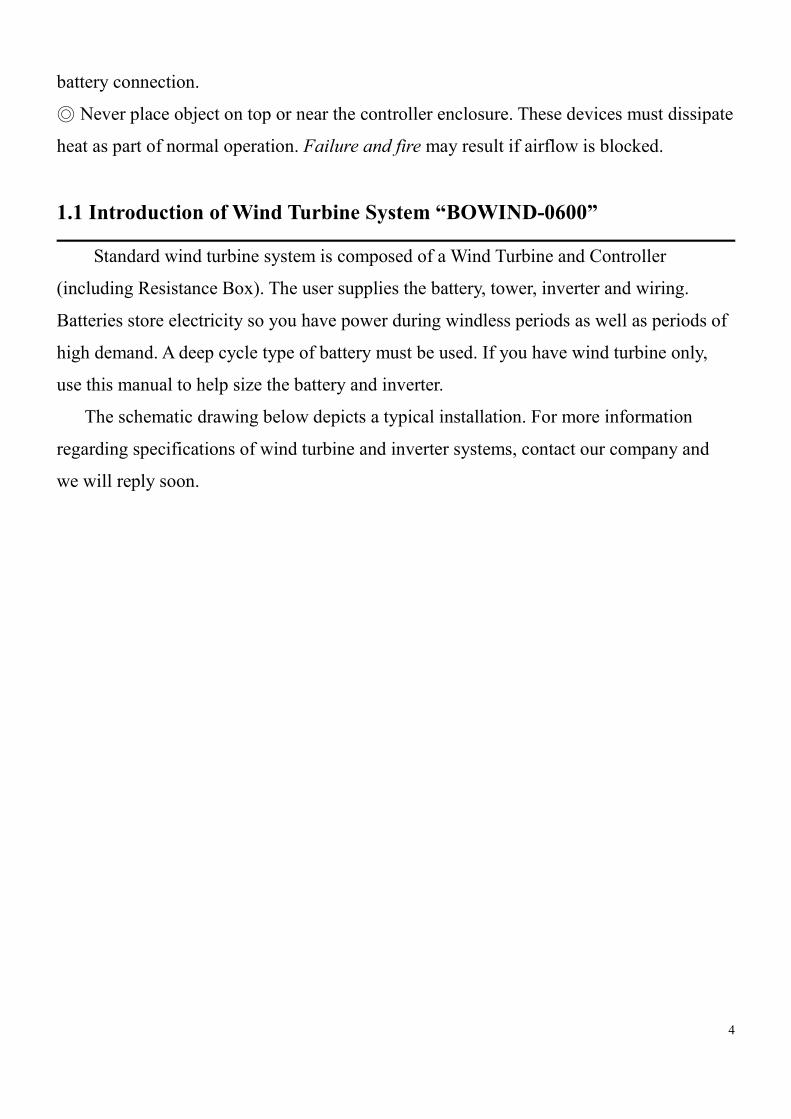
Major Components of wind turbine “BOWIND-1200”

7
1.2 Tower Installation and Location Selection
Tower height minimum is 6 meters above trees or obstacles within 100m (300
feet).The highest point on your property is generally best. Besides, install a lightning rod
and its height should be higher than tower.
For example:
Tower height: 8M
Caliber: 76.3mm (thickness: 4mm)
Maximum loading of tower: 130kg (under 60m/s wind speed)
Deformity condition: wind velocity<60 m/s and total deformity is 0.75%
Minimum gap between blade and tower is 285mm
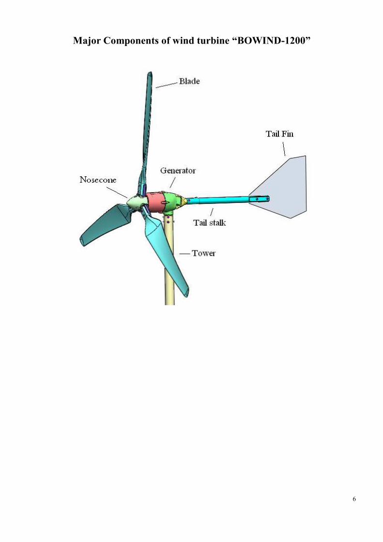
Tower size illustrates belong:
8
Crane size:
Single host & rope
Loading over 300kg (include tower)
Crane’s height should higher than tower over 1.5 meter
Loading of rope & hook should over the total weight of goods
1.3 Wind Turbine Electrical Tests
Before installing the wind turbine, please test the wind turbine first to check it can
work normally.
(1)Open Circuit Test:
The wind Turbine should spin freely when the wires are unconnected.
(2)Short Circuit Test:

9
The wind turbine should turn hard when all the wires are shorted together.
(3)Phase to Phase Test:
Using digital multi meter to measure any two wires of the wind turbine, it should
reveal short circuit condition.
The wind turbine electrical tests should satisfy above three conditions at the same
time. If any one is unsatisfied, it means the wind turbine is broken down. Please contact
factory or distributor soon.

10
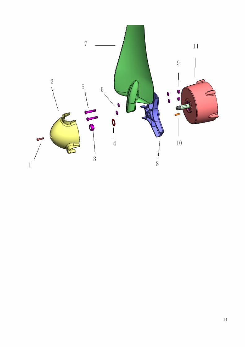
1.4 Wind Turbine components assembly schematic drawing
1.4.1 Blades & Nose Cone
Referring to the under drawing, align the fix column of blade and hub, then install
blade on hub and lock with bolts. Put pin on the pin slot of generator shaft. And align the
pin of hub and shaft, put hub on generator and install shaft and hub with M16 Nut. Lock
the nut with 20 N-m. Then install nose cone on hub and Lock it with 8 N-m.
No. Component Name & Size Quality
1 Cap Bolt M5X12 3
2 Nosecone 1
3 Nut M16 1
4 Washer M16 1
5 Hex Bolt M8X60 6
6 Washer M8 12
7 Blade 3
8 Nylon But M8 6
9 Hub 1
10 Pin 6X6X22 1
11 Generator 1

11
1.4.2 Tail Stalk & Wing
Referring to the under drawing, align the spiral hole of tail stalk and fin, and then
lock with hex bolts. When you lock the tail wing, lock carefully with 11 Nm. Wrong
installation will result in tail wing broken or tail stalk bent. Then put tail stalk around tail
set. After aligning the spiral hole, lock with 12Nm.
No. Component Name & Size Quality
1 Tail Set 1
2 Hex Bolt M8X12 3
3 Washer M8 5
4 Nylon Nut M8 2
5 Tail Stalk 1
6 Hex Bolt M8X45 2
7 Nylon Washer M8 2
8 Tail Fin 1

12
1.4.3 Wind Turbine & Tower
Put yaw set into tower, and lock with M8 hex bolt.
No Component Name & Size Quality
1 Yaw Set 1
2 Spring Washer 5
3 Washer M8 5
4 Nut M8 X 20 5

13
1.4.4 Suggestive Installation Order
Tail Wing
Tail Stalk
Blades
Hub
Nosecone

14
2. Controller
Installation Information
◎ Do not make it repaired and/or disassembled by unqualified person. If this happens,
the warranty becomes in effective.
◎ Do not place the controller in the humidity, and high temperature environment, or
directly under sun.
◎ Use only the battery with the same brand and type. Use of other battery is prohibited.
◎ Do not place any other substance close to the controller and resistor box.
◎ Connection electrical wires according to the wire connection diagram provided in
manual.
Safety Warning (Read the details before installation)
◎ Pay attention to the polarity of battery, and do not make short circuit for battery
polarity.
◎ During running, the electricity power will be generated in R.S.T conductors. Do not
touch them.
◎ Controller shall be installed indoor with appropriate water protection.
◎ Resistor box can be installed outdoor with appropriate ventilation and water
protection. Do not make it directly under rain shower.
◎ Resistor box shall be placed out of the reach of child to prevent the risk of electric
shock.
◎ The R.S.T doctors with minimum size of 12 AWG (4mm2) shall be used for R.S.T.
◎ For battery load and unload conductors (Bat +, Bat -, R+, R-), the copper conductors
with minimum size of 10AWG(6mm2) shall be used.
◎ Before installation, check to ensure if every battery voltage is within the limit of
(12±2)V.
◎ If any problem is found in the wire connection of controller. Stop operation of wind
turbine first, and check to ensure that the R.S.T conductors are well connected to

15
controller.
Before typhoon and/or hurricane, dismount the wind blade from wind turbine, and
well fixed them in appropriate location so as to prevent the damage to the wind
turbine and/or injury to the person.
Be sure to dress electricity protection gloves during making wire connection.
2.1 Controller outlook and connection points
The controller outlook is as the following drawing, its dimension is 315mm * 240mm
*95mm with 8P wire connection terminals as the following:
● R.S.T terminal: Power input ports (The input conductors could be connected
arbitrarily)
● 24V Battery connection terminals: marked with “BAT+”, and “BAT-”.
● Unload discharge connection terminals: marked with “R+”, and “R-”.
● Earth connection terminals: marked with “ ”.
● Controller max input unloaded voltage 150Vac.
● Battery max voltage 60Vdc.
● The max current 45 AMP.

16
◎Circuit Breaker:
Before maintenance, typhoon, or hurricane, switch the circuit breaker to “STOP”
position, and making sure that the wind turbine stops running completely, then you can
access to the wire connection circuit to carry out the maintenance and/or disassembly
work.
2.2 Indicator Explanation
Three LEDs (Green/Yellow/Red) are used on the controller to indicate the battery and
controller working conditions as the following explanation:
◎ Controller start: Green-Yellow-Red (light one cycle)
◎Whenever the battery is not fully charged, the LED lights as the following.
Green Lights 80%~95% charged
Green & Yellow Light 60%~80% charged
Yellow Lights 35%~60% charged
Yellow & red Light 0%~35% charged
Red Lights Battery Low
◎ Green Flashes Battery Full
The indicators as above mentioned indicate the situation of battery charging, it will be
different if you use other battery.
In case there is any other indication, it means that some abnormal situation is detected.
For this case, stop operation immediately and keep us informed for repair.
2.3 Unload resistor box outlook and function
The unload resistor box outlook is as the following diagram. It’s dimension is 440mm
* 330mm * 120mm.

17
During the operation of wind turbine, some additional generated power will be
delivered to the “unload resistor” depending upon the situation of battery charging. The
power delivered to the resistor will be transferred into heating power. So, the unload
resistor box shall be located outdoor with appropriate ventilation, protection against rain
shower, and out of the reach of Child. During operation of wind turbine, it is prohibited to
touch the “unload resistor box”.

18
2.4 Recommended battery specification and cable size
(1) Single battery voltage: 12 (Volts).
(2) Battery capacity: 75 (Amp/Hours).
(3) Lead acid deeply cycle battery without water adding.
◎Battery circuit:
Connect the four 12 Bolts lead acid battery in series with appropriate polarity as
indicated on the following drawing so as to get the 48 Bolts battery charging circuit.
During connection, pay attention to the right polarity. In case of error, it will result in the
damage to controller.
12 V
12 V
12 V
12 V
+
+
+
+
+
-
48 V
12 V
12 V
12 V
12 V
+
+
+
+
◎Cable:
The power cable for R.S.T shall be at least 12 AWG (4 mm2)Copper Conductor with
Voltage rating 600V, current rating 30A, and temperature rating 180℃。
The cable for battery charging and unload circuit shall be at least 10AWG(6 mm2)
copper conductor with 600V,45A,180℃。
In case the cable is exposed outdoor, it shall be protected by using appropriate cable
conduit.

19
2.5 Installation Steps
The wire connection for controller and Loading Resistor Box shall be completed
prior to the running of wind turbine.
1. Switch the circuit breaker to “Stop” position.
2. Connect the battery and loading resistor box with proper polarity, and check to
ensure that battery and resistor can work normally.
3. Connect the power conductors from wind turbine to R/S/T terminals.
4. Set up the generator of wind turbine for operation.
5. Switch the circuit breaker to “Start” position so as to start the operation of wind
turbine.
R S T BAT+BAT- R+ R-
Boltun Controller
RST
+ -Battery Load

20
2.6 Recommended Inverter Specification
For this series of wind turbine, we strongly recommended 2 set of batteries used
alternatively instead of inverter. However, if required you may use appropriate inverter to
transfer 48 Vdc power to the appropriate local power specification ranging from 100
Vac~240Vac/50~60Hz so as to make it supply the appropriate power to your electrical
equipments.
12 V
12 V
12 V
12 V
+
+
+
+
+
-
48 V Inverter+
- OUTPUT100~240Vac / 50~60Hz

21
3. Operation & Maintenance
◎Attention: Before proceeding routine maintenance, must observe the wind turbine
close-down procedure.
3.1 Wind Turbine Operation Model
(1)Normal Model:
After installing completely the wind turbine system, switch the brake on controller to
work model, namely enter normal model. Wind Turbine can operate normally to generate
electricity.
(2) Manual-braked Model:
When you want to make the inspection, maintenance or before the typhoon coming,
switch the brake on controller to STOP model manually. The wind turbine will stop
rotating in order to make the inspection conveniently.
(3) Mechanical Auto-braked Model:
This wind turbine has mechanical braking structure. When the wind velocity over
than 12 m/s, the wind turbine furls it’s fuselage by using fuselage eccentric structure, and
lets the face of blade deviate the wind direction and reduce wind turbine’s rotational speed
to protects the generator, and reduces the occurrence of dangerous, as shown in Figure 3-1.
※According to IEC 61400-2 related rules, they pointed out that this wind turbine defines
the specific external condition does not use in the wind situation like covering the
disembark type or the hurricane, the tropical cyclone and the typhoon and so on tropical
storm. Therefore when the typhoon or the hurricane comes, please lower the wind turbine
from the tower to avoid the wind turbine suffering damage, and can protect the wind
turbine, the residence and the personal safety.

22
Figure 3-1 Mechanical auto-braking mode schematic drawing
Figure (a) operating in normal mode; figure (b) when the wind velocity around field bigger
than 12 m/s, the wind turbine will automatic furl ; figure (c) is vertical view; figure (d) is
side vertical view.
3.2 Maintenance
◎Attention: Before proceeding to the maintenance, make the following close-down
procedure:

23
(1) First transfers the brake to the position of stop rotation.
(2) Disassembles the both electrode of battery. (Attention: when you disassemble the
battery, please don’t short in order to avoid the accident.)
(3) Before proceeding to the maintenance, make sure that the wind turbine doesn’t
rotate.
(4) Needing to disassemble the wind turbine from the tower by crane.
(5) Forbids proceeding the maintenance under high wind velocity to ensure personal
security.
(1)Maintenance - Monthly
◎Noise Intensity:
Choose a calm day to hear whether there is any noise occurred underneath the wind
turbine while the wind turbine is rotating. Then, close the switch of manual-braked, and
hear whether there is any noise at the same time. Try to find the noise if indicated. Check
whether there is any bolts slipped and whether there is any damage on the wind turbine or
the tower. And repair it in shortest time to avoid the accident.
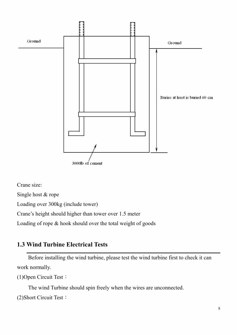
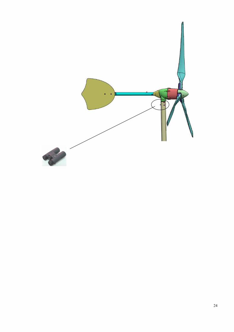
◎Mechanical Condition:
Use binocular to check whether there is no mechanical noise, rattle or vibration. And
the propeller and tail must not wobble. Lower or climb the tower for inspection, if
indicated. There should be no buzzing either heard or felt with your hand on the tower
base.
24
25
◎Tower Inspect:
Follow all inspection and maintenance requirements of the tower manufacturer.
Tighten all nuts and bolts, especially wire clips. Check for cracks and bent or broken parts
at the anchors and base structure. Check for broken strands and tighten guys.
◎ Battery:
As using Lead-acid battery, you should check the height of electrolyte. If it’s low,
refill it. Check the surface and both electrode of battery. Then clean it.
(2)Maintenance - Monthly
Lowers the tower and does a completely mechanical inspection to wind turbine. Fixes
or replaces any worn or Loose Parts. And spurts WD-40 rust remover around various
attached parts.
Checks the fixed bolts and nuts on tower base, and makes sure that they are locked
tighten. And the wind turbine is also.
Checks all bearings, and rotates them gently by your hand to check it is smooth.
Cleans the dust and fragment on wind turbine and avoids abrasion its surface. Checks the
blades, and if they have the breakage or damage, replace the blades.
◎Attention: Above steps can be proceeding by training operator, and do not need
receiving special training servicemen.

26
3.3 Maintenance Log
Observe the monthly and annual inspection required! Record all maintenance and
repair works!
Date Problem/Observation Action take

27
3.4 Troubleshoot & Repair
The following steps may be proceeding by training operator, and do not need
receiving special training servicemen. Other problem only can be proceeding to
installation and maintenance by receiving special training servicemen.
First, it’s necessary to determine if the problem is mechanical or electrical. Refer to the
drawings below and then proceed to the appropriate section.
Blade does not turn (Or turns slowly)
= mechanical problem.
Proceeds according to Table: Symptoms of
Mechanical Problems
Blade turns slowly = Electrical
problem.

28
Table: Symptoms of Mechanical Problems
Symptom Possible Cause Correction
1. Propeller is stationary,
even in high winds
a. Loose, broken or
rubbing magnet
b. Bad or worn bearing
a. Contact factory or
distributor to replace it
b. Contact factory or
distributor to replace it
2. Propeller will not turn
at all expect in high wind,
scraping or rubbing sound
at low rpm, always at
same propeller position
a. Same as above, expect
more likely to be high
magnet or bad bearing
a. Contact factory or
distributor to replace it
3. Propeller is harder
rotating, output is lower &
there is more propeller
noise than usual, and
seems out of balance
a. Split, warped or
damaged blade
a. Contact factory or
distributor to replace
broken or damage blade.
4. Tail, generator and
tower vibrate or shack
excessively at all or some
wind speeds
a. Blade out of balance
b. Blade not tracking
c. Rotor (magnet can) out
of balance
a. Contact factory to
replace blade
b. Contact factory to
replace hub
c. Return to factory or
distributor
5. Rattle or clunking from
generator
a. Generator loose in
tower, tail set loose, tail
wing loose, and wires
slapping inside of tower.
b. Worn bearings or
shaft broken
a. Inspect for damage,
repair as required,
retighten various
attached parts
b. Contact factory to
replace bearings or shaft

29
Trouble Shooting for the electrical parts failure
Feature Possible reasons Recommended Handling
Provisions
Blade is stand still,
even in high wind
speed
1.The circuit breaker is
notswitched to “start”
position
1.Switch circuit breaker to
“start” position
Blade can not be
braked
2.The cable of wind
turbine is not connected to
controller
2.Connect the R/S/T
conductor cable to the
R/S/T terminals of
controller
In high wind speed
condition for a long
period of time, but
the battery is still in
low charge condition
3.Battery break, or battery
is out of maintenance.
3.Maintain battery or
replace battery if it breaks.

30
3.5 Mechanical Repair & Parts Replacement
※※※※WARNING: Do not attempt these repairs on top of the tower. Perform repairs
only after tower has been lowered.
Complete components of wind turbine BOWIND-0600 was listed as follows:
BOM Of BOWIND-1200
NO. Part Name & Character Quality
1 Cap Bolt M5X12 3
2 Nosecone 1
3 Nut M16 1
4 Washer M16 1
5 Bolt M8X60 6
6 Washer M8 20
7 Blade 3
8 Nylon Nut M8 24
9 Hub 1
10 Pin 6X6X16 1
11 Generator 1
12 Tail Stalk 1
13 Bolt M8X12 3
14 Tail Fin 1
15 Nylon Washer M8 2
16 Yaw Set 1
17 Bolt M8X16 5
18 Spring Washer M8 5
31

32

33
17
18
19

34
4. The related condition of our product guarantees against damage
From the purchased date in two years, so long as any component of the wind turbine
suffers damage or the flaw, may be free replaced by a new one. But except the following
situation which causes the wind turbine to suffer damage, please pay attention:
a. Under fierce wind speed (typhoon or hurricane)
b. The wrong way of wind turbine installing
c. The wrong connection of the circuit of battery system.
d. The fragment in air causes the blade damaged.
e. Natural disaster (earthquake and flood)
f. Disassembles the controller without permission.

35
Appendix A
1. Combination wrench:
The specification is 13mm, and suggested you prepares two, as soon as may also
prepare to put up matches the socketfix wrench use, uses in installing tail set, tail stalk and
tail wing.
2. Socketfix wrench & socket set:
Suggest you prepares 1 set, uses the 13mm socket to match the 13mm combination
wrench to operate the wrench to install the hub and blades.
3. Adjustable wrench:
Model 250mm(10”) above, uses to lock the M16 nut on the hub and the shaft of
generator.
4. Hexagon wrench:
Model 5mm, uses to lock the hub and the nose cone.
5. Electronic side cutter:
Use to Cut out wind turbine’s three-phase electric wire, as well as overall system's
electric wire (controller, battery and so on), make the three-phase line connection.
6. Terminal:
Use to fix the three-phase electric line of wind turbine, the three-phase input of the
controller, and the positive and negative electrode of battery to connect all circuit of
system.
7. Wire Crimping:
Use to fix the terminal clamped on wire without falling off.
8. Single & three core electric wire:
The single-core electric wire uses to make the battery series-parallel connection, but
three-core electric wire uses for to link up the wind turbine and the controller system,
causes the electricity which the wind turbine sends to deliver the controller. Then the
controller transfers the alternating current to the direct current, and charges the battery.
9. Electric tape:
Use to paste the electric wire exposed place, the post fixed place and the engagement

36
place, let the wiring work is safer, reduces the occurrence of the situation which the wind
turbine burns down because of the three-phase short circuit or the personnel receives an
electric shock and so on dangerous situation.
10. Digital multi meter:
When you finish the installation of wind turbine and the connection of controller
system, use digital multi meter to measure the circuit of wind turbine is connected.
11. Cross-type screwdriver:
When you connect the three-phase electric line of wind turbine with the controller,
you can use Cross-type screwdriver to lock electric line on the controller.

37
Boltun Corporation
No.1, Hsin-Tien 2nd St, Jen-Der Xiang
Tainan Hsien, Taiwan
TEL:886-6-2794013
FAX:886-6-2706186
E-mail: [email protected]
http://www.boltun.com/energy