boulder amateur television club tv repeater's repeater · tv rptrs rptr-24.doc (kh6htv,...
TRANSCRIPT

TV Rptrs Rptr-24.doc (kh6htv, 11/4/2019) p. 1 of 11
Boulder AmateurTelevision Club
TV Repeater'sREPEATER
November, 20193ed Edition
Jim Andrews, KH6HTV, editor - [email protected] www.kh6htv.com Free Distribution: The BATVC newsletter is being circulated widely to other ATVhams and repeater groups throughout the US and to CQ-DATV. Beyond the 18 activelocal ATV hams, it presently is going to about 60 other hams. We do know that some ofthem then send it out further to their club members. Feel free to pass it on to your otherATV ham buddies. If reprinted, in whole or part, we do ask that you include anacknowledgement of us as the source.
( tnx to Michelle, N5NYV for this nice graphic ! )BATVC NET: The Boulder ATV group meets for an informal net every Thursdayafternoon. The net starts at 3pm local time. Net control is Don, N0YE. The net usesthe Boulder ATV repeater, W0BTV. Video inputs are: 23cm digital, 1243MHz, DVB-T;70cm digital, 441MHz, DVB-T, and 70cm analog, 439.25MHz, NTSC, VUSB-TV.Repeater output is digital on 423MHz, DVB-T. Antenna polarization is vertical. Ourintercom frequency is on the BCARES 2 meter FM voice repeater (146.76MHz, -600,100Hz tone required). The live net typically lasts for 1 to 1 1/2 hours. There is usuallysome DVD program playing for about 1/2 hour prior to and also 1/2 hour after the livenet. All licensed hams are invited to participate even if they do not have a videotransmitter.
TV Rptrs Rptr-24.doc (kh6htv, 11/4/2019) p. 2 of 11
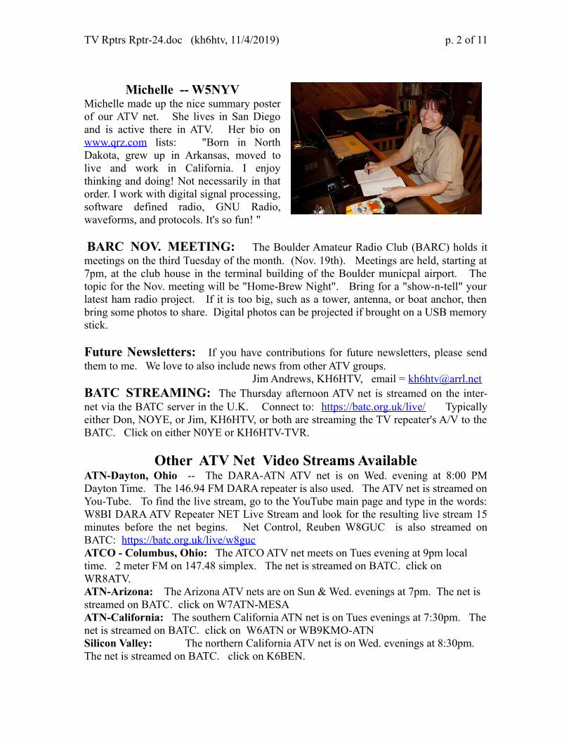
Michelle -- W5NYVMichelle made up the nice summary posterof our ATV net. She lives in San Diegoand is active there in ATV. Her bio onwww.qrz.com lists: "Born in NorthDakota, grew up in Arkansas, moved tolive and work in California. I enjoythinking and doing! Not necessarily in thatorder. I work with digital signal processing,software defined radio, GNU Radio,waveforms, and protocols. It's so fun! "
BARC NOV. MEETING: The Boulder Amateur Radio Club (BARC) holds itmeetings on the third Tuesday of the month. (Nov. 19th). Meetings are held, starting at7pm, at the club house in the terminal building of the Boulder municpal airport. Thetopic for the Nov. meeting will be "Home-Brew Night". Bring for a "show-n-tell" yourlatest ham radio project. If it is too big, such as a tower, antenna, or boat anchor, thenbring some photos to share. Digital photos can be projected if brought on a USB memorystick.
Future Newsletters: If you have contributions for future newsletters, please sendthem to me. We love to also include news from other ATV groups.
Jim Andrews, KH6HTV, email = [email protected] BATC STREAMING: The Thursday afternoon ATV net is streamed on the inter-net via the BATC server in the U.K. Connect to: https://batc.org.uk/live/ Typicallyeither Don, NOYE, or Jim, KH6HTV, or both are streaming the TV repeater's A/V to theBATC. Click on either N0YE or KH6HTV-TVR.
Other ATV Net Video Streams AvailableATN-Dayton, Ohio -- The DARA-ATN ATV net is on Wed. evening at 8:00 PMDayton Time. The 146.94 FM DARA repeater is also used. The ATV net is streamed onYou-Tube. To find the live stream, go to the YouTube main page and type in the words:W8BI DARA ATV Repeater NET Live Stream and look for the resulting live stream 15minutes before the net begins. Net Control, Reuben W8GUC is also streamed onBATC: https://batc.org.uk/live/w8guc ATCO - Columbus, Ohio: The ATCO ATV net meets on Tues evening at 9pm local time. 2 meter FM on 147.48 simplex. The net is streamed on BATC. click on WR8ATV.ATN-Arizona: The Arizona ATV nets are on Sun & Wed. evenings at 7pm. The net is streamed on BATC. click on W7ATN-MESAATN-California: The southern California ATN net is on Tues evenings at 7:30pm. The net is streamed on BATC. click on W6ATN or WB9KMO-ATNSilicon Valley: The northern California ATV net is on Wed. evenings at 8:30pm. The net is streamed on BATC. click on K6BEN.
TV Rptrs Rptr-24.doc (kh6htv, 11/4/2019) p. 3 of 11
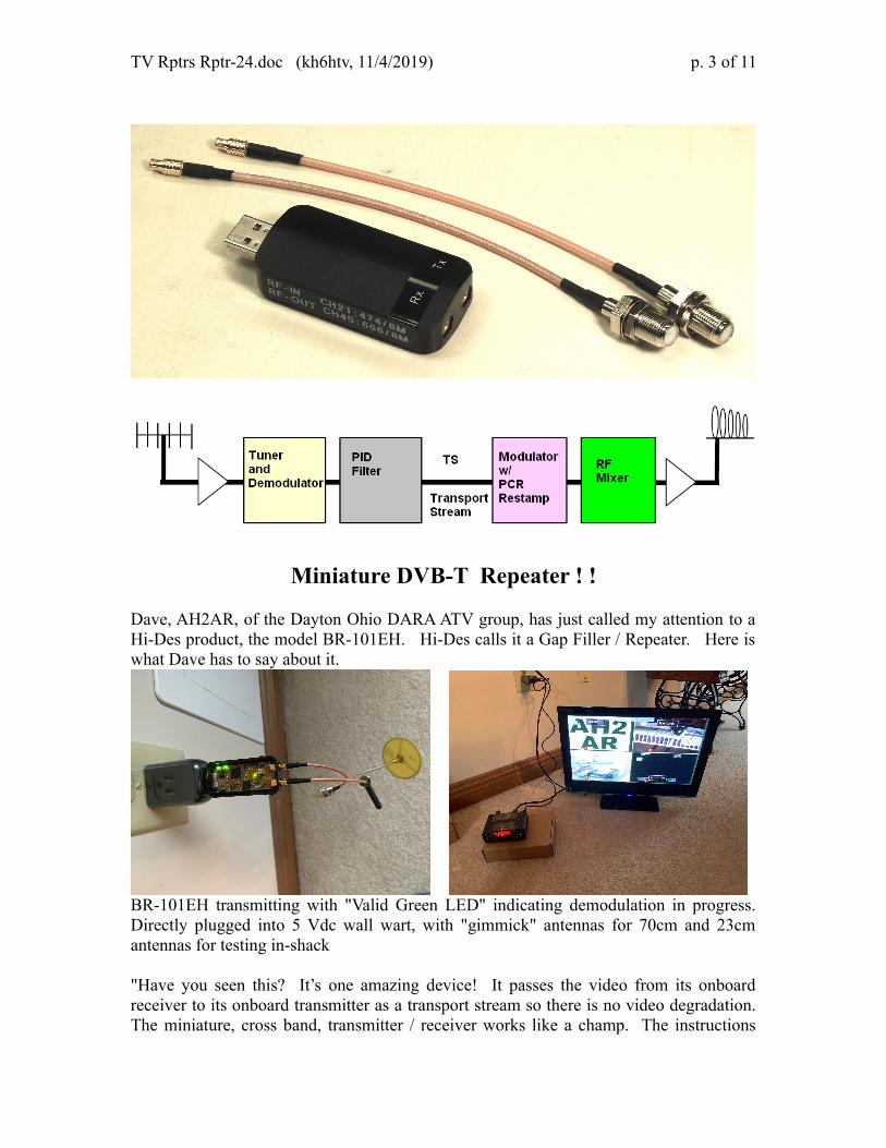
Miniature DVB-T Repeater ! !
Dave, AH2AR, of the Dayton Ohio DARA ATV group, has just called my attention to aHi-Des product, the model BR-101EH. Hi-Des calls it a Gap Filler / Repeater. Here iswhat Dave has to say about it.
BR-101EH transmitting with "Valid Green LED" indicating demodulation in progress.Directly plugged into 5 Vdc wall wart, with "gimmick" antennas for 70cm and 23cmantennas for testing in-shack
"Have you seen this? It’s one amazing device! It passes the video from its onboardreceiver to its onboard transmitter as a transport stream so there is no video degradation.The miniature, cross band, transmitter / receiver works like a champ. The instructions

TV Rptrs Rptr-24.doc (kh6htv, 11/4/2019) p. 4 of 11
aren’t real clear but it was easy to set up regardless. It’s picking up my transmitted signalon 439 MHz and is seamlessly passing the video on 1280 MHz on to a distant (down inthe basement!) HV-122A receiver. This has great potential as a leg of a cross bandrepeater or gapfiller. This is an amazing device as it is totally self contained and does notrequire a computer to run and once the parameters are set up in its configuration menu,it’s plug and play. The only limiting factor is that the transport stream between thereceiver and transmitter is a throughput stream only and the audio that passes throughcan’t be manipulated. But still, the stereo audio, along with the video is not degraded viaany encoding decoding process as it is repeated."
"When powered on, the BR-101E providesa continuous output with a blank rasterwhen it is not receiving for about oneminute after the received signal leaves theair, then the modulator ceases transmissionuntil another signal is received. It also hasa CALLSIGN feature that can be set to anyunique callsign within its graphical userinterface during initial configuration.When an incoming signal drops, ittransmits the call sign as a 60 second trailerand then stops transmitting.When receiving a distant signal, it re-transmits whatever DVB-T signal it is receiving andthere is absolutely no degradation of the re-transmitted video as it uses a transport streaminternally between its demodulator and modulator so no video or audio data is lost.Although not clearly seen in the photo, the two separate HDMI monitors in the photoshow the HDMI signal on 439 Mhz before entering the BR-101EH and also the re-transmitted signal from the BR-101EH on 1280 Mhz. There is virtually no discernibledifference in video quality when compared side-by-side."
"Here is the BR-101 driving a Mini-Circuits ZHL-42W amplifier with about 1watt output (relative reading only) showingon the Bird 43. The skirts were about-30dB. This would drive a W6PQL XRF-286 amplifier nicely. The BR-101 is warmto the touch, to the point that I would put afan on it at a repeater site. The amplifieris cool to the touch after 1/2 hour running.The BR-101 outputs only -12 dBm."
"For cross-band repeater use it works superbly. I have as-of-yet to see whether it willwork for in-band repeater use because modulator/demodulator de-sensing will likely willbe an issue, since there is no physical isolation between modulator and demodulator andconsequently likely won’t work for that purpose, but as I get further into this, I will seewhether this is even feasible.

TV Rptrs Rptr-24.doc (kh6htv, 11/4/2019) p. 5 of 11
Lastly, when it is demodulating a DVB-T signal, the PCB has a “green valid signal LED”that can be exploited to switch a relay or provide other functions. The valid signal LEDis used on other HiDes receivers for relay control switching and there is no reason whythis methodology can’t be employed with the BR-101Eto support other functions also.
These and other functions need further checkout and I still have to figure out how thecallsign features work on this unit. Its there, but the instructions are a little unclear (forme!): Hopefully, Jim Andrews KH6HTV will be able to provide a further in-depthreview of this unique "micro" gapfiller/repeater that literally can be lost inside yourpocket! "---------------Key specs. from the Hi-Des web site ( http://www.hides.com.tw/product_BR101eh_eng.html ) are:Receiver freq. range = 50-950MHz; Transmitter freq. range = 50-950 & 1200-1350MHz;Bandwidths 2 to 8MHz; RF power out = -4dBm, & -18dBm (1.2G band), MCX rfconnectors, runs on USB power of 5Vdc at 390mA. Size is a large USB dongle Price is$239 (shipping included)-----------------------------------------------------------------------------------------------------------
The following amplifier article was submitted by John, W0BCMC, the trustee for theOmaha, Nebraska 70cm, ATV repeater. John says this about his amplifier, " Very linearon NTSC, should work for DTV/8VSB as well." When I was doing the research for theATV repeater directory last winter, John sent me this note about their Omaha repeater.
"It is on the air here in Omaha. It's on the highest spot in the city limits and about 350feet above that on a radio tower. Still analog, NTSC, and TPO of 200 watts. It is capableof almost 300 but clips sync too much at that. 434 in and 421.25 out. We do get someinterference from some part 15 devices on 433.95. Other than that it has run flawlesslysince we put it in back in march. Of note, the side band filter on the TX is a commercial10KW model tuned down from broadcast Ch. 48. 0.5dB loss and aural LSB reject of-75dBc. < 0.2dB ripple in the pass band. I'm only on my first cup of coffee so if youwant more info just ask."
A QUARTER KILOWATT AMPLIFIER FOR 420-440 MHZJohn Gebuhr - WB0CMC
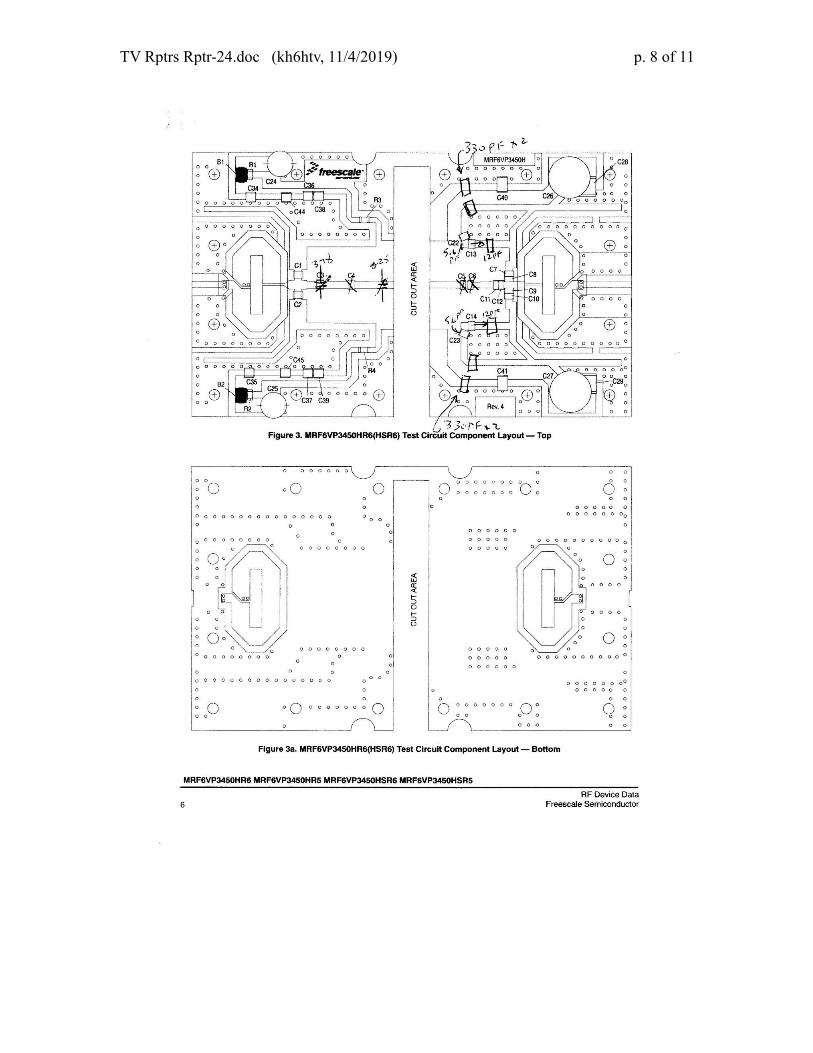
I built one for our ATV repeater about two years ago. It has had good service with onlyone failure. One of the 5.6pF caps blew up and dropped the power and linearity by quitea bit. I chalk it up to “infant mortality” of the cap. The amp will do 300 Watts CW but tomaintain good linearity I’m running it at 200 Watts sync power. Sync clips pretty well at250-300 watts. The device will do 400 watts but it needs the full 50 volts and a bit moredrive. Gain of the amp is 28 dB and efficiency about 50%. It uses an MRF6VP3450Htransistor using the layout recommended by the manufacturer. It was originally aMotorola device but others now also make it, NXP, for one. DC components are per themanufacturers values. Those in the RF sections differ for the lower frequency in bothplacement and values. For the input: C1, C2 are 27pf, C3 is a 3-18pf trimmer, C4 is a 8-

TV Rptrs Rptr-24.doc (kh6htv, 11/4/2019) p. 6 of 11
25pf trimmer moved as close to the gates as possible. The two are somewhat inter-dependent so I kept them variable. All else is per the Mfr. For the output: C5 and C6 notused, C7 and 8 are an uncased mica of 25pf as are C9 and 10, case on drain Cu, tab tobalun. C11 and 12 not used. C13 and 14 are 12pf and are located exactly midway alongthe ground copper to the left of C13 and 14 as shown by mfr. C22 and 23 are 5.6pf.There are 2 330pf caps where the drain lead goes around the corner at the end of thestraight section from the supply and the left corner of the ground copper, one on eitherside of the +line to ground. All chip caps must be hi-Q, low loss and able to operate in a50 volt DC system. See diagram below. ATC recommended. Values are for 421.250MHz, some are slightly less for 434.000. Other than the one cap failure it has been inICAS for over two years. Circuit board is Rogers 4003C 1e/1e 0320. It is a good idea touse a 2 or 3dB attenuator on the input to keep any back feed from damaging the exciter.½ a watt or so will drive it to 250 watts. For the power supply I used a 36volt and 10 voltsecondary with a split primary (useful if one wants to run it on 240VAC). The 36voltshould have at least 10A capacity, the 10 volt at least 2A. Other parts are: 35A full wavebridge rectifier, 6 18000 microfarad/63 volt electrolytics, 4 10000 microfarad/at least16volts, 7805 TO220 regulator, 8 amp fuse and holder, power switch and whateverindicators you may want. STBY voltage is about 52 volts, TX is 48. 12.5 and 11 if the12 volts runs the exciter. I had two of the transformers but they must have been less than10 A because one on the original model got rather warm under continuous operation.Paralleling the two, they run cool.
Entire amp and power supply close up of amp
Front of amp in transmit with color bars(2 ¼ A) Amp in STBY with exciter & coffee warmer

TV Rptrs Rptr-24.doc (kh6htv, 11/4/2019) p. 7 of 11
Top of exciter, original prototype on 434 MHz Front of exciter, audio & FM mod circuits in box
Bias Layout
The meters came from M P Jones for $3 each. They draw about 10-15 ma from the source. Drain current meter came from the junk box.
TV Rptrs Rptr-24.doc (kh6htv, 11/4/2019) p. 8 of 11

TV Rptrs Rptr-24.doc (kh6htv, 11/4/2019) p. 9 of 11
5 cm Band Spectrum AnalysisJim Andrews, KH6HTV
As part of a potential project to put amateur DTV on the 5cm band, I first performedsome measurements of what potential RFI I might encounter.
5 cm Ham TV Frequencies ---- The 5 cm amateur radio band covers from 5.65 to 5.925GHz. The ARRL band plan allows wide-band modes ( > 1 MHz bandwidth ) in two, 75MHz, segments: 5.675 to5.75 GHz and 5.85 to 5.925 GHz. It should be noted that this isanother band shared with unlicensed, ISM transmitters. The ISM band is from 5.725 to5.875 GHz. The 5.8 GHz band is not quite as heavily used by unlicensed Wi-Fi, etc. asthe 2.4 GHz band. However, this will not last long and it may soon be another "junk"band, lost to radio amateurs, if not already. To avoid 5.8 GHz Wi-Fi, we should probablyfirst put our TV operations in the 50 MHz segments of 5.675 to 5.725 GHz or 5.875 to5.925 GHz. I have purchased some inexpensive, import, FM-TV transmitters for the 5.8GHz band and found they were using frequencies from 5.645 up to 5.945 GHz. Theyincluded the following frequencies which fall in the amateur band at 5.665, 5.685, 5.705,5.885 and 5.905 GHz.
I propose we channelize the lower 5.675-5.725 segment into 6 MHz channels as follows:Ch 5cm-1 = 5675-5681, fc = 5678MHz Ch 5cm-2 = 5681-5687, fc = 5684MHz, etc.
So, all things considered, my first choice for experimenting with DTV at 5 cm would be5cm-1 at 5678 MHz. Will it work ? ? ?
To first determine what backgroundRFI exists on the 5cm band, I set upan experimental receiver with aspectrum analyzer to monitor theband. I used an L-Com, 5.8GHz,BBQ grill antenna (23dBi) withhorizontal polarization. I feed this toa lash-up receiver consisting of anAvantek, 4-8GHz, 13dB amplifierfeeding an Anzac 4-18GHz diodemixer. The LO for the mixer was aFrequency West brick running at6.092GHz. The IF output from themixer went to my Rigol DSA-815,1.5GHz, Spectrum Analyzer.
I have a good view of the city of Boulder from the window of my ham shack. The city isabout 5 miles to the west with empty open space prairie between us. I placed theantenna looking out the window towards Boulder to see what, if any, RFI I would beable to detect on the 5cm band. Unfortunately, I found it ! ! !

TV Rptrs Rptr-24.doc (kh6htv, 11/4/2019) p. 10 of 11
5cm Band Activity from the city of Boulder 1.5 GHz sweep from 6.1(left) to 4.6GHz(right)
Looking at the lower sideband from the mixer 0 MHz (left side) on the analyzer displaywas thus 6092MHz while 1.5GHz (right side) on the analyzer display was 4592MHz.This first measurement shown above was doing the full 1.5GHz sweep from 6.1 down to4.6GHz with the analyzer put in the Peak Hold mode and allowed to run for a 1/2 hour.Yellow trace is the peak hold result. Magenta trace is the system noise level with theantenna disconnected and a 50 Ω termination on the receiver input. Cyan trace is onesingle sweep. The vertical scale in each plot is 10dB/div. (Note: Some of what is beingseen could also be upper-sideband from 6.1 to 7.6GHz as there was no 5.8GHz band-pass filter used, except for the selectivity of the antenna.)
5cm RFI in 5.675-5.750 ATV band (peak hold 1/2 hour) center = 5717MHz, 100MHz span
5cm RFI in 5.675-5.750 ATV band (peak hold 1 minute) center = 5717MHz, 100MHz span
The 2ed measurement was then to see what RFI was in the desired 5cm ATV band. Inthe above photos, the center frequency is 5717 MHz. The span is 100 MHz coveringfrom 5767(left) to 5667(right). The yellow trace is again the Peak Hold for a duration of1/2 hour. The magenta trace is the system noise level. Needless to say, I was dismayed atwhat I saw. So, my next measurement was to repeat this, but only do the Peak Hold for ashort duration of about one minute. This was more encouraging, because the signalswere not always there. The last measurement was to narrow in the sweep and only lookat ATV channel 5cm-1 (5678 MHz). see below photo. The signals captured on the 1hour acquisition are fortunately not always present.

TV Rptrs Rptr-24.doc (kh6htv, 11/4/2019) p. 11 of 11
RFI detected in desired ATV channel, 5cm-1, center freq = 5678 MHz, 20 MHz span.yellow trace is Peak Hold mode with 1 hour accumulation. Cyan trace is single sweepwhile magenta trace is no antenna, system noise level.
CONCLUSION: We will encounter RFI in the 5cm band to our ATV transmissions.But they should be intermittent and not be a permanent problem. However, we will needto chose our operating frequency carefully.
Now our next project is to actually go out in the field with 5cm DTV gear and see whatwe can accomplish. (winter weather permitting ! ! )--------5 cm Comments from Bill, K0RZ: The narrow band portion of the 5 cmband is the 2 MHz slot from 5759 to 5761 MHz. The center portion 5760 to 5760.1 isdedicated to EME activity. Bill said "The 5 GHz amateur band, particularly 5760.1 is aloss for any future DX SSB activity here. The S meter is constantly pulsing S9 to 20 dBover S9 depending on where my dish is pointed."
5cm SSB band - center = 5760 MHz, 2 MHz span
After receiving Bill's comments, I then used my 5cm receiver and spectrum analyzer tosee what RFI in the SSB band I got with my antenna. The above plot is looking at theSSB band from 5761 (left side) to 5759 (right side). Center frequency is 5760MHz.This is Peak Hold for a 1 hour acquisition time. Bill's antenna is in a much higherlocation than mine. Bill lives on the top of Davidson Mesa with a commanding, almost360 degree view. Plus his 5cm dish antenna is located on the top of his tower with arotator.