bouc-wen model parameter identification for a …umpir.ump.edu.my/id/eprint/13165/1/fkp - mohd...
TRANSCRIPT
BOUC-WEN MODEL PARAMETER IDENTIFICATION FOR A NEW MAGNETO-
RHEOLOGICAL FLUID DAMPER USING PARTICLE SWARM OPTIMIZATION
MOHD AZRAAI BIN MOHD RAZMAN
Thesis submitted in fulfilment of the requirements
for the award of the degree of
Master of Engineering (Manufacturing)
Faculty of Manufacturing Engineering
UNIVERSITI MALAYSIA PAHANG
SEPTEMBER 2014
v
ABSTRACT
In constructing a reliable semi-active suspension system, the modelling of the
damper is imperative as it produces the controllability on the suspension system. The
modelling of Magneto-rheological (MR) fluid damper for the control device has been
major focuses throughout the decades as semi-active systems are deems to be efficient
in vibration suppression for various applications. MR fluid damper is abided by the
behaviour of hysteresis model that not just predict the subsequent impact, but has the
ability to retract the motion by the model internal memory. Acquiring a suitable model
comes a setback from the natural existence of non-linearity from the MR fluid damper
as the parameters of the hysteresis model may requires tuning as the response time for
the absorber to response are in milliseconds. Hence, Particle Swarm Optimization
(PSO) was introduced for altering significant parameters for Bouc-Wen hysteresis
model to replicate the MR fluid damper performance in real-time. The objectives are
succinct in three main criteria starting with the development of MR fluid damper, then a
representation of hysteresis model and lastly optimizing these parameters by inducing
PSO algorithm. Validations by physical experiment and simulation were conducted to
enhance the justification of the present model. These performances are measured in
force against displacement and force against displacement for the hysteresis model to
depict MR fluid damper behaviour. The average marginal error was presented to
strengthen the model along with analysis and discussion in deliberating the outcome.
Approximation of the model demonstrates dependable fitting compared to the
experimental data with the average marginal error ranging from 6.0 % to 8.3 %. The
findings suggest that several parameters of the hysteresis systems requires boundary and
by imposing the known sensitive variables to the model can emulated into near perfect
model.

vi
ABSTRAK
Dalam pembinaan sebuah sistem pergantungan separa-aktif, pembikinan struktur
terhadap penyerap adalah penting untuk menghasilkan sistem pergantungan yang boleh
dikawal. Untuk membikin struktur peredam cecair MR sebagai bahan kawalan telah
menjadi tumpuan utama sejak kebelakangan dekad apabila sistem separa-aktif ini
dikatakan berfungsi secara telus dalam mengagihkan gegaran bagi aplikasi yang meluas.
peredam cecair MR ini mengandungi tingkah laku yang diperoleh dari struktur
histeresis yang bukan sahaja boleh mengagak impak di masa hadapan, malah
mempunyai kebolehan untuk menjejak kembali pergerakkan dengan kehadiran imbasan
dalaman. Memenuhi sebuah modal yang sesuai, datangnya kekurangan dari lumrah
azali pengkadaran yang tidak melurus dari peredam cecair MR di mana parameter-
parameter histeresis modal mugkin memerlukan penalaan pada tindak balas masa yang
berlaku dalam masa yang singkat milisaat. Jadi, Pengoptimuman Kawan Partikel (PSO)
digunakan untuk mengubah parameter-parameter yang terbabit bagi struktur histeresis
bagi menghasilkan struktur peredam cecair MR dalam waktu semasa. Objektif-objektif
utama terbahagi kepada tiga bermula dari penghasilan peredam cecair MR, penyerupaan
struktur hysteresis dan akhir sekali mengoptimumkan parameter-parameter dengan
mengunakan algoritma PSO. Bukti dari eksperimen secara fizikal dan simulasi di
jalankan untuk memperkukuhkan bukti penggunaan stuktur yang dilancarkan. Prestasi
ini diukur melalui daya melawan kelajuan dan daya melawan ralat kedudukan. Purata
beza dibentangkan bagi memperkuatkan analisa serta perbincangan atas hasil yang
dikeluarkan. Anggaran dari struktur ini menunjukkan kebergantungannya terhadap
eksperimen di dalam lingkungan 6.0 % ke 8.3 % purata perbezaan. Penemuan
berasaskan atas dasar parameter-parameter daripada hysteresis memerlukan lingkungan
dan dengan menyeterai pemalar yang sensitif untuk menghasilkan modal yang telus.
vii
TABLE OF CONTENTS
Page
SUPERVISOR’S DECLARATION ii
STUDENT’S DECLARATION iii
ACKNOWLEDGMENTS iv
ABSTRACT v
ABSTRAK vi
TABLE OF CONTENTS vii
LIST OF TABLES x
LIST OF FIGURES xi
LIST OF SYMBOLS xiii
LIST OF ABBREVIATIONS xv
CHAPTER 1 INTRODUCTION
1.1 Research Background 1
1.2 Problem Statement 3
1.3 Research Objective 3
1.4 Research Scope 4
1.5 Research Methodology 5
1.6 Thesis structure 7
CHAPTER 2 LITERATURE REVIEW
2.1 Introduction 8
2.2 Magneto-rheological Damper 8
2.2.1 Damper Advancement and Classification 10
2.2.2 Magneto-rheological damper characteristic 12
2.2.3 Magneto-rheological damper element and structural design 13
2.3 Hysteresis Model 20
2.3.1 Hysteresis modelling comparison and trend 21
viii
2.3.2 Comparison Parametric Models 22
2.3.3 Bouc-Wen Modelling Development 26
2.4 PSO Development and Applications 31
2.4.1 PSO Model Formulation 32
2.4.2 Background of PSO 33
2.4.3 PSO Algorithm 35
2.4.5 Parameter Control in PSO 37
2.5 Summary of the Review 39
CHAPTER 3 RESEARCH METHODOLOGY
3.1 Introduction 41
3.2 Experiment Framework 40
3.2.1 Development of MR damper 43
3.2.2 Test rig 50
3.2.3 Hardware and System Integration 49
3.2.4 Perform Experiment 50
3.3 Simulation Structure 53
3.3.1 Method of Parametric Identification and PSO Configuration 53
3.3.2 Software Application 54
3.3.3 Computer Parameter Search 55
3.4 Evaluation, Results and Discussion Structure 55
3.5 Summary 55
CHAPTER 4 RESULTS AND DISCUSSION
4.1 Introduction 57
4.2 MR damper Characteristic 58
4.3 Experiment validation of parametric model comparison 63
4.3.1 Consequent Findings on Bouc-Wen model by Kwok 72
4.4 Supplementary Analysis 78
4.5 Summary 80
ix
CHAPTER 5 CONCLUSION
5.1 Introduction 84
5.2 Summary of Thesis 84
5.3 Research Conclusion 86
5.4 Findings and Contribution 87
5.5 Suggestion for Future Work 87
REFERENCES 88
APPENDICES
A PSO Programming Code 95
B Hysteresis Parameter Coding 96
C Main Simulink 97
D List of Publications 98
x
LIST OF TABLES
Table No. Title Page
2.1 Parametric Identification classification 24
3.1 Shock absorber measurement 45
3.2 MR damper parameters of geometric and magnetic design 49
3.3 Input parameters and output data 50
4.1 Mean of parametric models force error (N) 71
4.2 Percentage of force error for various test conditions 80
4.3 Parameters value for various test conditions of Bouc-Wen by Kwok 81
model

xi
LIST OF FIGURES
Figure No. Title Page
1.1 Flowchart of research methodology activities 6
2.1 Suspension schematic 9
2.2 Classification of suspension system 11
2.3 MR damper schematic 12
2.4 Fluid flow (a) choking point flow (b) passive mode 13
(c) magnetize mode
2.5 Valve mode flow 14
2.6 Squeeze mode MR flow 16
2.7 Shear Mode flow 17
2.8 Mono-tube damper segments 20
2.9 Model parameters formation 27
2.10 Hysteretic Interpretation 28
2.11 Schematic model 29
2.12 Topology of PSO social network 36
3.1 Methodology flowchart 41
3.2 Original absorber of Proton Waja 44
3.3 MR fluid damper assembly 45
3.4 Shock Absorber Measurement 46
3.5 Force-velocity plot of original absorber 46
3.6 MR damper valve mode of the shock absorber 47
3.7 Electromagnetic coil inside damper "choking points" 48
3.8 Design of parameters in choking points 49
xii
3.9 MR fluid damper employment 51
3.10 MR fluid dampers Equipment 52
4.1 Displacement over time for passive absorber 58
4.2 Displacement over time of test conditions 59
4.3 Forces over time current input comparison 60
4.4 Force against displacement for various test conditions 61
4.5 Force against velocity for various test conditions 62
4.6 Error comparison gauge measurement 63
4.7 Comparison of data for Bingham model with 0.0 A 65
4.8 Simulink circuit of Bouc-Wen model 63
4.9 Comparison of data for Bouc-Wen model with 0.0 A 66
4.10 Comparison of data for Bouc-Wen by Kwok model with 0.0 A 67
4.11 Bingham model comparison for various test conditions 68
4.12 Bouc-Wen model comparisons for various test conditions 69
4.13 Bouc-Wen model by Kwok comparisons for various 70
test conditions
4.14 Comparison of hysteresis models 70
4.15 Model comparison of mean deviation force error 72
4.16 Data comparison of Bouc-Wen by Kwok (2007) model for 0.0 A 73
4.17 Data comparison of Bouc-Wen by Kwok (2007) model for 0.5 A 74
4.18 Data comparison of Bouc-Wen by Kwok (2007) model for 1.0 A 75
4.19 Data comparison of Bouc-Wen by Kwok (2007) model for 1.5A 76
4.20 Data comparison of Bouc-Wen by Kwok model for input current 77
4.21 Force error comparisons for various test conditions 79
4.22 Percentage error comparisons for various test conditions 80
4.23 RMSE comparison of hyteresis models 82
xiii
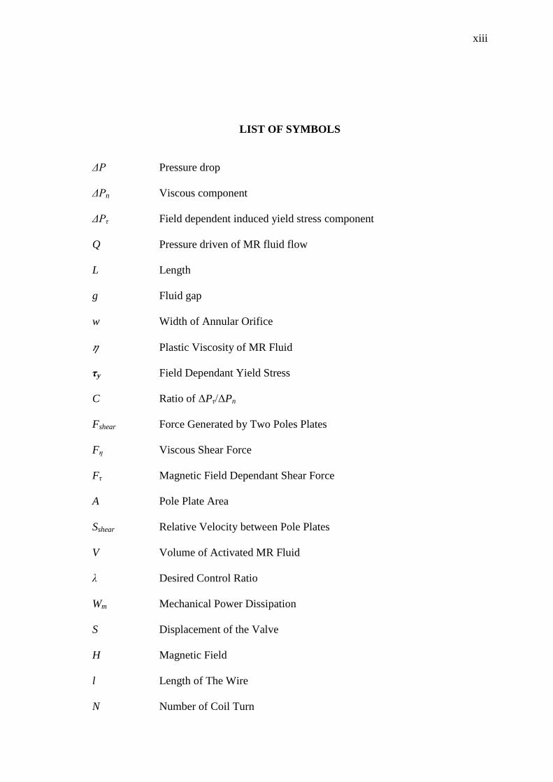
LIST OF SYMBOLS
ΔP Pressure drop
ΔPn Viscous component
ΔPτ Field dependent induced yield stress component
Q Pressure driven of MR fluid flow
L Length
g Fluid gap
w Width of Annular Orifice
Plastic Viscosity of MR Fluid
τy Field Dependant Yield Stress
C Ratio of ΔPτ/ΔPn
Fshear Force Generated by Two Poles Plates
Fη Viscous Shear Force
Fτ Magnetic Field Dependant Shear Force
A Pole Plate Area
Sshear Relative Velocity between Pole Plates
V Volume of Activated MR Fluid
λ Desired Control Ratio
Wm Mechanical Power Dissipation
S Displacement of the Valve
H Magnetic Field
l Length of The Wire
N Number of Coil Turn
xiv
i Current Supplied to the Coil
µ Relative Permeability of the Material
µ0 Free Space Permeability
Bc Magnetic Strength For The Core
Bw Magnetic Strength At The Wall
ϕ Magnetic Flux
Bg Magnetic Strength At Fluid Gap
Ag Cross Sectional Areas of the Fluid Gap
Ac Cross Sectional Areas of the Core
Aw Cross Sectional Areas of the Cylinder Wall
tg Fluid Gap
lc Core Length
lw Wall Length
c Viscous coefficient
k Stiffness Coefficient
α Scaling factor of hysteresis
z Hysteresis Displacement
β Hysteresis Parameter
γ Hysteresis Parameter
δ Hysteresis Parameter
m Mass
u(t) Displacement
F(t) Restoring Force
f(t) Excitation Force
Fy Yield Force
xv
uy Yield Displacement
z(t) Dimensionless Hysteretic Parameter
sgn(•) Signum Function
n Exponential Parameter
ke Initial Stiffness
kp Post-Yielding Stiffness
f Damping Force
f0 Damper Force Offset
τy(field) Yield Stress Induced by the Magnetic Field
Nonzero Piston Velocities fc The Magnitude of Hysteresis
pbest Best Position
gbest Best Global Value
lbest Best link
Initial Swarm Particles of Positions
Initial Swarm Particles of Velocity
ith
Number Of Particle
rand Uniformly Distributed Random Variable
Best Global Value
vmax Maximum Velocity
φ Constant Acceleration
c1 Constant Acceleration
c2 Constant Acceleration
w Inertia Weight
D1 Wire Hole inside The Hollow Shaft

xvi
D2 Internal Diameter of The Piston Ring
D3 Inner Diameter of Internal Piston
D4 Outer Diameter of Piston Ring
D5 Height of Magnetic Choke
G Fluid Gap
W Flange Thickness
A Ampere
Fexp Experimental Data
Fsim Simulation Data
xvii
LIST OF ABBREVIATIONS
2D Two dimensional
3D Three dimensional
ANFIS Adaptive Neuro Fuzzy Inference System
BW Bouc-Wen
DAQ Data Acquisition
DS Design Space
EH Electro-Hydraulic
ER Electro-rheological
GA Genetic Algorithm
LVDT Linear Variable Differential Transformer
MR Magneto-rheological
MTS Material Testing System
PSO Particle Swarm Optimization
RMSE Root-mean-square error
SGA Standard Genetic Algorithm
CHAPTER 1
INTRODUCTION
1.1 RESEARCH BACKGROUND
Semi-active suspension application throughout the decades has seen promising
potential predominantly on the stability and robust nature for controlling exerted
vibrations in automotive particularly. Hence, the role of influencing the vibration is
obliged by the damper. Magneto-rheological (MR) fluid is alleged to be a smart
material that able to alter its resistivity with pertinent operation. In despite of the
adaptable condition designated for the MR fluid damper, the sophistication on modeling
the behavior has been scrutinized ever since.
Orientation of iron particles inside the MR fluid is influenced by the strength of
the magnetic field that is dignified from the amount of current induced. Hence the
resistive force that constraint the flow of fluid through orifice inside the piston is
competent to regulate viscosity for the entire MR fluid damper system. In spite of
having the feature to manipulate the restrictive force, the development of MR fluid
damper ought to be realized. In drafting the suitable MR fluid damper in synchronizing
with parametric identification, several factors are required to perform the investigation
in intention for modeling and parameter identification. These aspects include the
dimension of damper, geometric structural and magnetic design.
Identification methods withal have endured the modeling of MR fluid damper as
an alternative source in replicating its performance. Supplementary, the bearing of MR
fluid damper possesses hysteresis model systems. It relies on the current state

2
inclusively with prediction of the forthcoming situation. Various techniques were
applied in order to realize onto a leading model. Methods that are frequently associated
with modeling are categorized either parametric or non-parametric. The importance of
prototyping is to formulate the groundwork for applying into control strategies before
extending the execution for semi-active suspension. Nevertheless, the complexity of
modeling the MR fluid damper is erratic knowing the fact that absorber has nonlinearity
feature. Furthermore, the drawback of hysteresis model is the presence of dynamic halt
during intermission of input and output. An explicit hysteresis system called Bouc-Wen
model suggested by Kwok demonstrates substantial quality as a modeling method to
match the behavior of MR fluid damper (Kwok et al., 2006). It was modified from
initial models discovered by Bouc in 1971 and further enhanced by (Wen, 1976) up till
now it is well recognized as Bouc-Wen model. Kwok et al. (2006) revised certain traits
from Bouc-Wen to ensure the stability of the hysteresis and performances to depict the
MR fluid damper were consented.
In furtherance of imitating the MR fluid damper, Particle Swarm Optimization
(PSO) method was introduced to enhance the parameter search for identification. The
concept of PSO is emulating the social behaviors of wildlife interaction primarily in a
clustered movement for instance in a flock of birds or swarming ants. The collaboration
between (Kennedy and Eberhart, 1995) had leaded a renowned optimization method and
has been seen in diverse application ever since. Subsequent to the motion of these
groups, it has similar analogy to acquire best parameter value, for instance a flock of
birds finding source of food in randomize formation until the location is found by
another bird hence the position is predicted as an optimized position. This analogy is
then applied onto the hysteresis model to locate the finest possible value in imitating the
MR fluid damper characteristics.
Parametric modeling have arisen several drawbacks during processing as the
domain of control force range is larger than the passive absorber. Subsequently the
development of MR fluid damper has subjective limitations especially on the properties
of amending the viscosity which rely on the amount of applied magnetic field. Thus the
accuracy of modeling the hysteresis model has become major dispute amidst existing
identification approaches. In addition to emerging complications, PSO has to endeavor
3
the assignments of recalculating the utmost suitable parameters values for curve fitting
of MR fluid damper model. Under these circumstances, extensive researches are
required to increase the performances of hysteresis model that represents MR fluid
damper. This is by the agency of implementing PSO algorithm to optimize the
parameters values subsequently enhancing hysteresis model in replicating the MR fluid
damper.
The main purpose of this research is to implement PSO to optimize the
parameter values of the Bouc-Wen hysteresis model proposed by Kwok et al. (2006)
that depicts the behavior of MR fluid damper.
1.2 PROBLEM STATEMENT
To acquire data from MR fluid damper and to be manipulated for optimization, a
number of interjections must be sorted out prior to finalizing the end results.
1) The foremost predicament would be raised from designing the modular
MR fluid damper that can satisfy emulating the behavior for parametric
identification. In specific would be the coil design correlates to viscosity
changes for given current input.
2) Modeling the MR fluid damper in hysteresis structure may result in
uncertainties and augmented noise.
3) Optimizing using PSO carries the setback of depicting the hysteresis
models in which the PSO parameters need to consider tolerance result
and account the hysteresis parameters that are adjustment sensitive.
1.3 RESEARCH OBJECTIVE
Based on the research motivation, raised several queries:
1) Determine the functional and practical MR fluid damper that qualifies
to be tested and compared with simulation from the structural and
magnetic design.
4
2) Suggest an algorithm of PSO that is able to optimize the parameter value
for hysteresis model that represents the MR fluid damper behavior using
Bouc-Wen hysteresis model.
3) Determine the receptive hysteresis parameters that alter the behavior of
MR fluid damper.
In this research, three hypotheses have been reached which are:
1) The structural design of MR fluid damper has distinctive specifications
as the relation of resistive force and magnetic field strength influenced
by current input.
2) Parameter values of Bouc-Wen hysteresis model proposed by Kwok
capable of being optimized by using the advocated PSO algorithm.
3) There will be several hysteresis parameters that delicate towards the MR
fluid damper modeling which leads to fluctuating results
The objectives of research are realized as:
1) To compose a control algorithm that proficient in enhancing the best
parameters value by integrating experimental and simulation study
consequently reproducing a noteworthy model of MR fluid damper to be
utilize as a model controller of semi-active suspension device.
2) To prove that several hysteresis parameters are certainly requires
regulation to generate agreeable MR fluid damper model and by
deducing these boundaries the replication of a more realistic hysteresis
model are practicable.
1.4 RESEARCH SCOPE
To reach the objectives as mentioned, the research scope has been clarified:
1) This research only focuses on mono-tube damper that has one reservoir
for the fluid to flow. The structural and magnetic design is solely on the
magnetic choke, the area of fluid passing through the orifice.
5
2) An original equipment of shock absorber was employed to enclose the
primary objective of designing the dimension at magnetic choke to
generate a bounded force and permitted operating current. The data
collected from MR fluid damper performance was classified under
distinguished test condition.
3) The parameter identification method proposed only on the algebraic
function. The comparison of models was done within this subject to
validate the leading model and subsequently the main reason is to
optimize an existing model.
4) PSO algorithm was employed to enhance the performance of hysteresis
Bouc-Wen models. The findings of the hysteresis parameters were
amplified to depict the experimental data of the MR fluid damper for
various test condition. The algorithm is preset to a reduce uncertainties
of parameter search and was employed only as a method of parameter
enhancer.
1.5 RESEARCH METHODOLOGY
The research activities were done in four stages. Firstly, the reviews on the development
of MR fluid damper, hysteresis model and parameter identification were done. It was
done for the comprehension on the current technology expansion with respect to MR
fluid damper modeling using parametric identification and the algorithm PSO.
Next is the structural and magnetic design modification on the original damper.
The proposed MR fluid damper is based on the operating platform for collecting data by
experiment. When the design was finalized, the data was collected in various test
conditions and stored for impending modeling verification.
Third, parametric identification was imposed beforehand in replicating the
behavior of MR fluid damper. The algebraic function from a number of hysteresis
models was steered by comparing selected models, Bingham, Bouc-Wen and Bouc-
Wen by Kwok. Simulation method was operated in investigating these models either by
employing MATLAB or Simulink reliant from the model intricacy. Significant
6
parameters that initiate the modeling of hysteresis model profile were identified. The
assessment was preceded to PSO algorithm for optimizing the suitable model for
reproducing the MR fluid damper performance. Optimization method was done via
MATLAB code parallel to the hysteresis model acquired by parametric identification
stage.
Lastly the verification of the simulation results with reference to the
experimental data was attained by elementary statistics procedure. Parameters acquired
from the enhanced hysteresis models are examined. The validation on the best fitting
model is investigated through the marginal error and further justified by the percentage
error on each point between retrieving records experimentally and the numerals results
from simulation. For every test condition the outcome was observed and justification for
the results was deliberated.
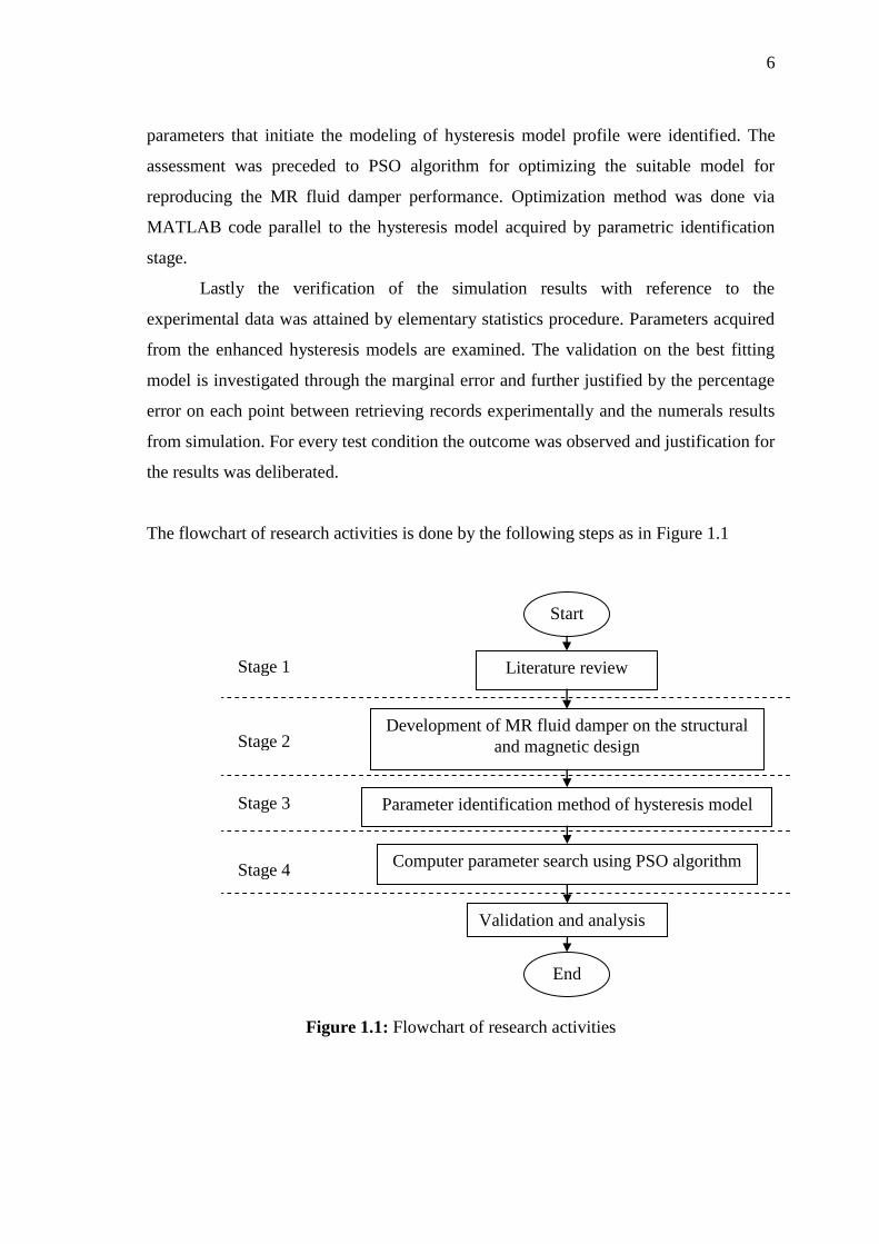
The flowchart of research activities is done by the following steps as in Figure 1.1
Figure 1.1: Flowchart of research activities
Start
Literature review
Development of MR fluid damper on the structural
and magnetic design
Parameter identification method of hysteresis model
Computer parameter search using PSO algorithm
Validation and analysis
End
Stage 1
Stage 2
Stage 3
Stage 4
7
1.6 THESIS STRUCTURE
This thesis is structured as follows:
Chapter 2: Literature review – discussion on the MR fluid damper development,
parametric hysteresis modeling, PSO algorithm in the perspective of background and
research literature.
Chapter 3: Research methodology – the outline of research development is extracted
into hardware and simulation phases from elaborating on the MR fluid damper design
and collecting damper performances the simulation synthesizing and overall evaluation
results can be achieved.
Chapter 4: Results and discussion – results obtained from previous chapter was
deliberated for analysis apprehension. The prime hysteresis model was determined from
hysteresis comparison, implementation of PSO has enhanced the model and optimized
parameters were resolved. The justification was done by underlining the error between
experimental and simulated results.
And lastly Chapter 5: Conclusion – conclusion of the entire experiment based on the
construction of this research and proposed improvements for future research work.
8
CHAPTER 2
LITERATURE REVIEW
2.1 INTRODUCTION
In this chapter, a review on the MR fluid damper design, hysteresis model
comparison and PSO operation is discussed. The review follows the basis of this
research according to practical realization of this project. Three main aspects on this
review will sum up extending to the scope for generalizing the research project.
MR fluid damper is a type of controllable device which has the property to
change its viscosity depending on the applied magnetic field. Hysteresis model depicts
the behaviour of the damper correlates to the input/output relationship. Parametric
model are based on mechanical principle including interpretation by arranging springs
and dashpot. PSO)is an optimizing technique based on population and individual search
finding from emulating social interaction (i.e. bird flocks) (Kennedy and Eberhart,
1995).
2.2 MR FLUID DAMPER
The MR fluid is defined as a smart material that can shift its property and early
discovery was dated back in the 1940’s (Rabinow, 1948; Winslow, 1947; Winslow,
1949). The manipulative system allows vibrations suppression ploughed on the
performance in civil and mechanical structures. A survey was conducted where MR
fluid damper as a semi-active devices, in which a property can be accustomed
immediately but the system cannot receive energy (Dyke and Spencer, 1997). The
9
versatility and adaptability of active systems are maintained by these device and act as
dependant passive devices denote recognition for MR fluid damper to be unswerving.
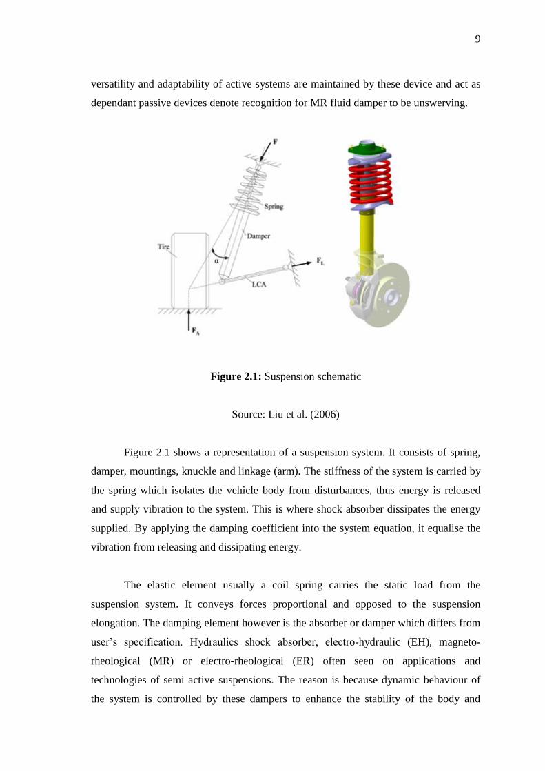
Figure 2.1: Suspension schematic
Source: Liu et al. (2006)
Figure 2.1 shows a representation of a suspension system. It consists of spring,
damper, mountings, knuckle and linkage (arm). The stiffness of the system is carried by
the spring which isolates the vehicle body from disturbances, thus energy is released
and supply vibration to the system. This is where shock absorber dissipates the energy
supplied. By applying the damping coefficient into the system equation, it equalise the
vibration from releasing and dissipating energy.
The elastic element usually a coil spring carries the static load from the
suspension system. It conveys forces proportional and opposed to the suspension
elongation. The damping element however is the absorber or damper which differs from
user’s specification. Hydraulics shock absorber, electro-hydraulic (EH), magneto-
rheological (MR) or electro-rheological (ER) often seen on applications and
technologies of semi active suspensions. The reason is because dynamic behaviour of
the system is controlled by these dampers to enhance the stability of the body and
10
delivers negligible force at steady-state. The mechanical linkage element primarily links
up the suspension system to the body in other words sprung body to the unsprung mass.
2.2.1 Damper advancement and classification
Recent technologies on suspension systems have expanded to a new approach
that categorize each suspension technology on its significant characteristics (Hrovat,
1997; Guglielmo et al., 2008; Isermann, 2003). The first case of active suspension, it
can be narrowed down to three well executed applications on the active field; load-
levelling, slow-active and fully-active. The difference between all of these is the
actuation framework of the bandwidth that the suspension can withstand. For load-
levelling the bandwidth is at the fine underline of the main suspension dynamics,
however bandwidth between body and wheel dynamics, and full-bandwidth is the slow-
active and fully-active suspensions respectively.
There are two criterion to elaborate electronically controlled suspensions; energy
input and bandwidth. The main comparison to notify the differences between active and
semi-active is by energy insertion into the system. It is classified as 'Active' when
energy is 'supplied' to the system, on the other hand it is considered as 'semi-active'
when the suspension system is electronically customized to exclude energy insertion
apart from the energy to steer the electronic parts. If the suspension can 'lift' the vehicle
it said to be active or else it is semi-active systems.
Bandwidth is the other feature that characterizes the suspension system. It is the
element in such that the specific reaction-time response can be modified electronically.
Figure 2.2 represents the classification between passive, semi-active and fully active
suspension systems (Ikhouane and Rodellar, 2007).