bou310_2009q1_nw_businessobjects xi 3.0-3.1 universe design
TRANSCRIPT

BusinessObjects XI 3.0/3.1: UniverseDesign
Learner’s GuideBOU310
Contact For Any SAP Module Materials : [email protected] ll VISIT: www.sapcertified.com ll

Copyright© 2009 SAP® BusinessObjects™. All rights reserved. SAPBusinessObjects owns the followingUnited States patents,whichmay cover products that are offered and licensed by SAPBusinessObjects and/or affliated companies: 5,295,243; 5,339,390;5,555,403; 5,590,250; 5,619,632; 5,632,009; 5,857,205; 5,880,742;5,883,635; 6,085,202; 6,108,698; 6,247,008; 6,289,352; 6,300,957;6,377,259; 6,490,593; 6,578,027; 6,581,068; 6,628,312; 6,654,761;6,768,986; 6,772,409; 6,831,668; 6,882,998; 6,892,189; 6,901,555;7,089,238; 7,107,266; 7,139,766; 7,178,099; 7,181,435; 7,181,440;7,194,465; 7,222,130; 7,299,419; 7,320,122 and 7,356,779. SAPBusinessObjects and its logos, BusinessObjects, Crystal Reports®,Rapid Mart™, Data Insight™, Desktop Intelligence™, RapidMarts®, Watchlist Security™, Web Intelligence®, and Xcelsius®are trademarks or registered trademarks of Business Objects,an SAP company and/or affiliated companies in the UnitedStates and/or other countries. SAP® is a registered trademarkof SAPAG inGermany and/or other countries. All other namesmentioned hereinmay be trademarks of their respective owners.
Contact For Any SAP Module Materials : [email protected] ll VISIT: www.sapcertified.com ll

C O N T E N T S
About this CourseCourse introduction..................................................................................................xviiCourse description...................................................................................................xviiiCourse audience.......................................................................................................xviiiPrerequisites..............................................................................................................xviiiLevel, delivery, and duration...................................................................................xixApplicable certifications and designations.............................................................xixCourse success factors................................................................................................xixCourse setup................................................................................................................xixCourse materials.........................................................................................................xixLearning process..........................................................................................................xx
Lesson 1Understanding BusinessObjects UniversesLesson introduction.......................................................................................................1Defining BusinessObjects universe concepts.............................................................2
The semantic layer.................................................................................................2What is a universe?................................................................................................2What type of database schema is used?..............................................................4Classes and objects ................................................................................................5Advantages of a universe .....................................................................................6BusinessObjects Universe Designer components .............................................6Starting Universe Designer ..................................................................................6Using the Quick Design Wizard..........................................................................8Importing a universe ............................................................................................8Using Universe Designer module commands ..................................................9Saving and exporting a universe.......................................................................12Universe file names as identifiers......................................................................13Saving a universe definition as PDF .................................................................13Giving all users access to a universe ................................................................14Activity: Viewing a universe in Universe Designer........................................14
Using the universe development cycle.....................................................................16The universe development cycle process ........................................................16Preparation phase ................................................................................................17Analysis phase......................................................................................................19Planning phase.....................................................................................................20Implementation phase.........................................................................................21
iiiTable of Contents—Learner’s GuideContact For Any SAP Module Materials : [email protected] ll VISIT: www.sapcertified.com ll

Implementation phase 1: schema design..........................................................22Implementation phase 2: building the universe..............................................24Testing phase........................................................................................................25Deployment phase...............................................................................................26Updating/maintenance.......................................................................................27Updating/maintenance.......................................................................................27Activity: Planning a universe.............................................................................27
Quiz: Understanding BusinessObjects universes...................................................29Lesson summary..........................................................................................................30
Lesson 2Creating the Course UniverseLesson introduction.....................................................................................................31Describing the course database and universe ........................................................32
The course database.............................................................................................32Creating the universe .................................................................................................35
Setting the database connection.........................................................................35Data access drivers...............................................................................................35ODBC connection drivers...................................................................................36OLE DB connectivity...........................................................................................36Viewing, modifying, and deleting available connections..............................40Creating a new universe......................................................................................42Defining universe parameters ...........................................................................43Identifying the universe......................................................................................43Universe parameters............................................................................................44Definition tab........................................................................................................45Summary tab.........................................................................................................46Strategies tab.........................................................................................................47Controls tab...........................................................................................................48SQL tab...................................................................................................................49Links tab................................................................................................................50Parameters tab......................................................................................................50Activity: Creating a new universe and defining its connection....................51
Quiz: Creating the course universe...........................................................................52Lesson summary..........................................................................................................53
Lesson 3Building the Universe StructureLesson introduction.....................................................................................................55Populating the universe structure.............................................................................56
Designing a schema ............................................................................................56Schema design and the universe creation process..........................................56Adding tables .......................................................................................................56Manipulating tables in the universe structure.................................................59
Universe Design—Learner’s GuideivContact For Any SAP Module Materials : [email protected] ll VISIT: www.sapcertified.com ll

Activity: Populating the universe structure.....................................................62Defining joins in a universe........................................................................................64
About joins and SQL WHERE clauses .............................................................64Creating joins........................................................................................................65About join properties...........................................................................................67Editing the join expression .................................................................................68Using the Join SQL editor ..................................................................................68Detecting joins .....................................................................................................70Setting join cardinalities......................................................................................70About cardinality.................................................................................................70Setting cardinality manually or with the automatic detection tool..............71Displaying cardinalities ......................................................................................73Detecting cardinality automatically..................................................................75How is cardinality detected?..............................................................................75Detect cardinality for all joins.............................................................................76Best practices for setting join cardinality .........................................................77Join types ..............................................................................................................78Equi-joins ..............................................................................................................78Outer joins ............................................................................................................79Theta joins.............................................................................................................81Shortcut joins........................................................................................................82Self-restricting joins .............................................................................................83List Mode...............................................................................................................85Checking integrity ...............................................................................................86Activity: Defining joins in a universe................................................................87
Quiz: Building the universe structure......................................................................89Lesson summary..........................................................................................................90
Lesson 4Creating Dimension ObjectsLesson introduction.....................................................................................................91Describing classes and objects ..................................................................................92
Classes....................................................................................................................92Objects....................................................................................................................93
Creating classes and objects ......................................................................................95Creating classes....................................................................................................95Automatically creating classes and objects from a table ...............................97Defining a new object as a detail object............................................................98Working with classes and subclasses................................................................99Editing the object properties...............................................................................99Edit Properties: Properties................................................................................102Edit Properties: Advanced................................................................................103Edit Properties: Keys..........................................................................................104Edit Properties: Source Information................................................................104Copying and pasting objects.............................................................................105
vTable of Contents—Learner’s Guide

Find and replace ................................................................................................106Checking object integrity .................................................................................108Viewing parent tables........................................................................................109Testing objects ....................................................................................................110Activity: Creating and testing classes and objects.........................................110
Quiz: Creating dimension objects...........................................................................116Lesson summary........................................................................................................117
Lesson 5Creating Measure ObjectsLesson introduction...................................................................................................119Defining measure object concepts...........................................................................120
Measure objects concepts..................................................................................120How a measure object infers SQL ...................................................................121The query process .............................................................................................122Aggregation at SELECT level...........................................................................123Aggregation at projection level........................................................................123Setting selection and projection aggregates...................................................124
Creating measure objects..........................................................................................125Measure objects .................................................................................................125Testing measure objects.....................................................................................126Activity: Creating and testing measure objects.............................................127
Creating delegated measure objects........................................................................131What is a delegated measure?..........................................................................131How does the delegated measure work?........................................................132Using a delegated measure as a weighted average.......................................132Best practices for using delegated measures..................................................134When are delegated measures inappropriate?..............................................135Activity: Creating and using a delegated measure ......................................135
Quiz: Creating measure objects...............................................................................138Lesson summary........................................................................................................139
Lesson 6Resolving Loops in a UniverseLesson introduction...................................................................................................141Understanding loops ................................................................................................142
Recognizing loops..............................................................................................142Problems caused by loops ................................................................................142Loops in a universe schema and not in the database ...................................143What is the loop doing?.....................................................................................143Resolving loops ..................................................................................................144
Resolving loops using aliases ..................................................................................145About aliases ......................................................................................................145Detecting loops and inserting aliases .............................................................145
Universe Design—Learner’s Guidevi

Redefining objects .............................................................................................148Listing and renaming aliases ...........................................................................149Choosing which alias method to use ..............................................................149Resolving self-referencing join loops using aliases.......................................149Activity: Using aliases to resolve loops...........................................................151
Resolving loops using contexts................................................................................154About contexts....................................................................................................154Detecting and creating contexts ......................................................................157Creating objects for each context ....................................................................160Editing a context ................................................................................................160Testing contexts .................................................................................................161Updating contexts .............................................................................................162Loops and shortcut joins...................................................................................163Activity: Using contexts to resolve loops........................................................165
Quiz: Resolving loops in a universe .......................................................................170Lesson summary........................................................................................................171
Lesson 7Resolving SQL TrapsLesson introduction...................................................................................................173Understanding SQL traps and universes ..............................................................174
About SQL traps ................................................................................................174Detecting and resolving chasm traps......................................................................175
Chasm traps .......................................................................................................175Detecting chasm traps ......................................................................................176The chasm trap scenario ...................................................................................176Resolving chasm traps ......................................................................................179Using multiple SQL statements for each measure to resolve chasmtraps......................................................................................................................179Drawbacks to the multiple SQL statements for each measuremethod.................................................................................................................181Using contexts to resolve chasm traps ...........................................................183Activity: Resolving chasm traps.......................................................................184
Detecting and resolving fan traps ..........................................................................188Fan traps .............................................................................................................188The fan trap scenario ........................................................................................189Resolving fan traps.............................................................................................191Using aliases and contexts to resolve fan traps.............................................192Scenario of a fan trap with two tables in a one-to-many relationship........193Avoiding fan traps altogether .........................................................................195Activity: Resolving fan traps............................................................................196
Quiz: Resolving SQL traps ......................................................................................200Lesson summary........................................................................................................201
viiTable of Contents—Learner’s GuideContact For Any SAP Module Materials : [email protected] ll VISIT: www.sapcertified.com ll

Lesson 8Applying Restrictions on ObjectsLesson introduction...................................................................................................203Restricting the data returned by objects ................................................................204
Defining data restrictions .................................................................................204Methods of restricting data in end-user modules ........................................205Drawbacks to applying restrictions to objects ..............................................206An alternative to applying restrictions to objects .........................................207Restrictions using condition objects ...............................................................209Applying restrictions using the tables button ...............................................210Applying each type of restriction ...................................................................212Activity: Applying restrictions.........................................................................212
Quiz: Applying restrictions on objects ..................................................................215Lesson summary........................................................................................................216
Lesson 9Using @functions with ObjectsLesson introduction...................................................................................................217Using @functions.......................................................................................................218
Defining @functions ..........................................................................................218@prompt .............................................................................................................218@prompt syntax .................................................................................................219@select..................................................................................................................223@where.................................................................................................................225@aggregate_aware..............................................................................................229Activity: Using @functions...............................................................................230
Quiz: Using @functions with objects .....................................................................232Lesson summary........................................................................................................233
Lesson 10Using HierarchiesLesson introduction...................................................................................................235Understanding hierarchies and universes ............................................................236
Hierarchies..........................................................................................................236Working with hierarchies ........................................................................................238
Default hierarchies ............................................................................................238Custom hierarchies............................................................................................241The effect of custom hierarchies on default hierarchies ..............................242Time hierarchies ................................................................................................244Testing automatic time hierarchies .................................................................247Advantages and disadvantages of automatic time hierarchies ..................248
Universe Design—Learner’s GuideviiiContact For Any SAP Module Materials : [email protected] ll VISIT: www.sapcertified.com ll

Time hierarchies based on database functions .............................................248Advantages and disadvantages of database function timehierarchies...........................................................................................................249Table-based time hierarchies ...........................................................................250Advantages and disadvantages of table-based time hierarchies ...............251Activity: Using hierarchies................................................................................252
Quiz: Using hierarchies ............................................................................................254Lesson summary........................................................................................................255
Lesson 11Using Lists of ValuesLesson introduction...................................................................................................257Creating a list of values ............................................................................................258
What is a list of values?.....................................................................................258Using a list of values (LOV)..............................................................................258
Working with LOVs in Universe Designer ...........................................................259Associating an LOV with an object..................................................................259Setting options for generating LOVs ..............................................................261Editing the LOVs for the entire universe .......................................................262Adding data to the list by adding columns ...................................................263
Creating a cascading LOV .......................................................................................265Setting up a cascading LOV .............................................................................265Activity: Using a cascading LOV in Web Intelligence Rich Client.............267
Quiz: Using lists of values .......................................................................................268Lesson summary........................................................................................................269
Lesson 12Creating Derived Tables and IndexesLesson introduction...................................................................................................271Using derived tables .................................................................................................272
What is a derived table?....................................................................................272Adding derived tables ......................................................................................272Derived tables as lookup for multiple contexts.............................................274Nested derived tables........................................................................................276Creating nested derived tables.........................................................................276Activity: Adding derived tables.......................................................................278
Applying index awareness ......................................................................................280What is index awareness?.................................................................................280Setting up index awareness..............................................................................280Using an index awareness WHERE clause.....................................................283Activity: Setting up index awareness..............................................................283
Quiz: Derived tables and indexes ...........................................................................285Lesson summary........................................................................................................286
ixTable of Contents—Learner’s GuideContact For Any SAP Module Materials : [email protected] ll VISIT: www.sapcertified.com ll

Lesson 13Linking UniversesLesson introduction...................................................................................................287Understanding linked universes ............................................................................288
What are linked universes?...............................................................................288Using linked universes......................................................................................288Possible linking strategies ................................................................................289Advantages and limitations to linking............................................................291
Creating links between universes............................................................................292Linking universes ..............................................................................................292Including one universe within another...........................................................294When to link and when to include?.................................................................295Activity: Linking universes ..............................................................................296
Quiz: Linking universes............................................................................................298Lesson summary........................................................................................................299
Lesson 14Applying Universe Access RestrictionsLesson introduction...................................................................................................301Setting access restrictions on a universe ................................................................302
About security and universes ..........................................................................302Completing your restriction set settings.........................................................315Setting restriction group priority.....................................................................318Viewing user and group restrictions...............................................................319Activity: Setting access restrictions..................................................................321
Quiz: Applying universe access restrictions .........................................................322Lesson summary .......................................................................................................323
Lesson 15Managing UniversesLesson introduction...................................................................................................325Documenting universes ...........................................................................................326
Printing universe details...................................................................................326Printing options: General..................................................................................328Printing options: List Components..................................................................328Printing options: Full Description...................................................................329
Deploying universes..................................................................................................330About deploying a universe ............................................................................330What happens when you export a universe?.................................................330Importing a universe.........................................................................................334Working with multiple designers....................................................................335
Universe Design—Learner’s GuidexContact For Any SAP Module Materials : [email protected] ll VISIT: www.sapcertified.com ll

Maintaining universes ..............................................................................................338Reasons for universe maintenance..................................................................338Changes to the target database ........................................................................338Detecting changes to the universe...................................................................339Adding new tables to an existing universe ...................................................340The effect of changing objects ..........................................................................340
Deploying universes in multiple languages .........................................................342Translation Manager .........................................................................................342Activity: Translating a universe with Translation Manager........................346
Quiz: Managing universes........................................................................................348Lesson summary........................................................................................................349
Appendix AEnd-of-Course ChallengeCompleting the end-of-course challenge...............................................................351Customer scenario.....................................................................................................352Activity: Completing the end-of-course challenge - part 1..................................353Activity: Completing the end-of-course challenge - part 2..................................354
Appendix BUnderstanding Relational and DimensionalModelingUnderstanding the metadata...................................................................................355Data warehouses........................................................................................................356Online Transactional Processing systems..............................................................357Data Marts...................................................................................................................358Dimensional Modeling..............................................................................................359
Appendix CSQL syntaxes for other RDBMSAlternative SQL syntaxes for other RDBMS..........................................................361ORACLE......................................................................................................................361DB2...............................................................................................................................363MySQL.........................................................................................................................365Microsoft Access........................................................................................................367
Answer KeyQuiz: Understanding BusinessObjects universes.................................................371Quiz: Creating the course universe.........................................................................372Quiz: Building the universe structure....................................................................373
xiTable of Contents—Learner’s Guide

Quiz: Creating dimension objects...........................................................................374Quiz: Creating measure objects...............................................................................375Quiz: Resolving loops in a universe .......................................................................376Quiz: Resolving SQL traps ......................................................................................377Quiz: Applying restrictions on objects ..................................................................378Quiz: Using @functions with objects .....................................................................379Quiz: Using hierarchies ............................................................................................380Quiz: Using lists of values .......................................................................................381Quiz: Derived tables and indexes ...........................................................................382Quiz: Linking universes............................................................................................383Quiz: Applying universe access restrictions .........................................................384Quiz: Managing universes........................................................................................385
Universe Design—Learner’s Guidexii

A G E N D AUniverse Design
Introductions, Course Overview...........................................30 minutes
Lesson 1Understanding BusinessObjects Universes.....................45 minutes❒ Defining BusinessObjects universe concepts❒ Using the universe development cycle
Lesson 2Creating the Course Universe...............................................30 minutes❒ Describing the course database and universe❒ Creating the universe
Lesson 3Building the Universe Structure...........................................45 minutes❒ Populating the universe structure❒ Defining joins in a universe
Lesson 4Creating Dimension Objects..................................................75 minutes❒ Describing classes and objects❒ Creating classes and objects
Lesson 5Creating Measure Objects.........................................................1.5 hours❒ Defining measure object concepts❒ Creating measure objects❒ Creating delegated measure objects
Lesson 6Resolving Loops in a Universe....................................................3 hours❒ Understanding loops❒ Resolving loops using aliases❒ Resolving loops using contexts
xiiiAgenda—Learner’s Guide

Lesson 7Resolving SQL Traps.........................................................................1 hour❒ Understanding SQL traps and universes❒ Detecting and resolving chasm traps❒ Detecting and resolving fan traps
Lesson 8Applying Restrictions on Objects.................................................1 hour❒ Restricting the data returned by objects
Lesson 9Using @functions with Objects............................................45 minutes❒ Using @functions
Lesson 10Using Hierarchies......................................................................45 minutes❒ Understanding hierarchies and universes❒ Working with hierarchies
Lesson 11Using Lists of Values................................................................30 minutes❒ Creating a list of values❒ Working with LOVs in Universe Designer❒ Creating a cascading LOV
Lesson 12Creating Derived Tables and Indexes.................................75 minutes❒ Using derived tables❒ Applying index awareness
Lesson 13Linking Universes......................................................................30 minutes❒ Understanding linked universes❒ Creating links between universes
Lesson 14Applying Universe Access Restrictions.....................................1 hour❒ Setting access restrictions on a universe
Universe Design—Learner’s Guidexiv

Lesson 15Managing Universes.................................................................45 minutes❒ Documenting universes❒ Deploying universes❒ Maintaining universes❒ Deploying universes in multiple languages
xvAgenda—Learner’s Guide

Universe Design—Learner’s Guidexvi

About this Course
Course introductionThis section explains the conventions used in the course and in this training guide.
xviiAbout this Course—Learner’s Guide

Course descriptionThis core three-day instructor-led course is designed to give you the comprehensive skillsneeded to design, build and maintain BusinessObjects 6.5, BusinessObjects XI R1/R2, andBusinessObjects XI 3.0/3.1 universes.
You should attend this course to understand universe design concepts and terminology, aswell as the role of universes in relation to BusinessObjects reporting tools. The course providesan overview of the process for planning, designing and creating a universe and thenwalks youthrough the process of designing a universe that responds to identified requirements.
The business benefit of this course is that you learn best-practice methodology for creatinguniverses that respond to your reporting requirements. Through well-designed universes,report designers and business users are able to create reportswithout having to know anythingabout the underlying data source or structure.
Course audience
This course is designed to teach you how to design BusinessObjects universes using UniverseDesigner; using BusinessObjects 6.5, BusinessObjects XI R1/R2, or BusinessObjects XI 3.0/3.1.
New features covered in the XI 3.0/3.1 course that are not applicable to BusinessObjects 6.5 orXI R1/R2 learners include:• Creating a cascading list of values associated with a hierarchy of objects in a universe• Creating delegated measures• Creating nested derived tables• Using Translation Manager• Testing universe results in Web Intelligence Rich Client
The target audience for this course is anyone responsible for creating and designing universesusing Universe Designer, using BusinessObjects XI 3.0/3.1.
Prerequisites
If youwant to learn BusinessObjectsWeb Intelligence™RichClient reporting skills and concepts,this course is recommended:• BusinessObjects Web Intelligence XI 3.0/3.1: Report Design
If you want to increase your skill level and knowledge of BusinessObjects Web Intelligence™XI reporting skills and concepts, this course is recommended:• BusinessObjects Web Intelligence XI R2: Report Design
To be successful, you must have working knowledge of:• SQL and relational database management systems concepts and structures• Familiarity with the type of data and the logical structure of the databases in their
organization• Familiarity with BusinessObjects Web Intelligence report building
Universe Design—Learner’s Guidexviii

Level, delivery, and duration
This core instructor-led offering is a three-day course.
Applicable certifications and designations
This course is not applicable to any Business Objects Certified Professional programs.
Course success factors
Your learning experience will be enhanced by:• Activities that build on the life experiences of the learner• Discussion that connects the training to real working environments• Learners and instructor working as a team• Active participation by all learners
Course setup
Refer to the setup guide for details on hardware, software, and course-specific requirements.
Course materials
The materials included with the course materials are:• Name card• Learner’s Guide
The Learner’s Guide contains an agenda, learner materials, and practice activities.
The Learner’s Guide is designed to assist students who attend the classroom-based courseand outlines what learners can expect to achieve by participating in this course.
• Evaluation form
At the conclusion of this course, you will receive an electronic feedback form as part of ourevaluation process. Provide feedback on the course content, instructor, and facility. Yourcomments will assist us to improve future courses.
Additional resources include:• Sample files
The sample files can include required files for the course activities and/or supplementalcontent to the training guide.
• OnlineHelp
Retrieve information and find answers to questions using the onlineHelp and/or user’sguide that are included with the product.
xixAbout this Course—Learner’s Guide
Learning process
Learning is an interactive process between the learners and the instructor. By facilitating acooperative environment, the instructor guides the learners through the learning framework.
Introduction
Why am I here? What’s in it for me?
The learners will be clear about what they are getting out of each lesson.
Objectives
How do I achieve the outcome?
The learners will assimilate new concepts and how to apply the ideas presented in the lesson.This step sets the groundwork for practice.
Practice
How do I do it?
The learners will demonstrate their knowledge as well as their hands-on skills through theactivities.
Review
How did I do?
The learners will have an opportunity to review what they have learned during the lesson.Review reinforces why it is important to learn particular concepts or skills.
Summary
Where have I been and where am I going?
The summary acts as a recap of the learning objectives and as a transition to the next section.
Universe Design—Learner’s Guidexx
Lesson 1Understanding BusinessObjects Universes
Lesson introductionTo design effective and efficient universes for your business users, you need a generalunderstanding of their structure and application. It is also important to become familiar withthe process involved in building a successful universe.
After completing this lesson, you will be able to:
• Define BusinessObjects universe concepts• Use the universe development cycle
1Understanding BusinessObjects Universes—Learner’s Guide

Defining BusinessObjects universe conceptsIn order to effectively design universes, it is necessary to familiarize yourself with what auniverse is and how a universe is used. This unit gives a general introduction to BusinessObjects universes, and the semantic layer.
After completing this unit, you will be able to:
• Describe a universe• Describe BusinessObjects Universe Designer interface elements• Save, export, and import universes
The semantic layer
A semantic layer is a business representation of corporate data that helps end users access dataautonomously using common business terms. Developed and patented by Business Objects,it maps complex data into familiar business terms such as product, customer, or revenue tooffer a unified, consolidated view of data across the organization.
By using commonbusiness terms, rather than data language, to access,manipulate, and organizeinformation, it simplifies the complexity of business data. These business terms are stored asobjects in a universe, accessed through queries and reports.
The semantic layer insulates business users from underlying data complexity, while ensuringthe business is accessing the correct data sources and using consistent terminology. Benefitsinclude improved end-user productivity and greater business autonomy from IT in accessingdata.
What is a universe?
The BusinessObjects universe is the semantic layer that isolates business users from the technicalcomplexities of the databases where their corporate information is stored.
For the ease of the end user, universes are made up of objects and classes that map to data inthe database, using everyday terms that describe their business environment. This means thatby using a universe to create a query, users can retrieve exactly the data that interests themusing their own business terminology.
Universe Design—Learner’s Guide2Contact For Any SAP Module Materials : [email protected] ll VISIT: www.sapcertified.com ll

A BusinessObjects universe is a file that contains the following:• Connection parameters to a single data source.
• SQL structures called objects that map to actual SQL structures in the database such ascolumns, tables, and database functions. Objects are grouped into classes.
• A schema of the tables and joins used in the database. Objects are built from the databasestructures that you include in your schema.
Note: You associate data to universes by mapping to a data source. Data is not stored inthe .unv file.
The role of a universe
The role of the universe is to present a business-focused front end to the SQL structures in thedatabase. The data used in a universe schema depends greatly on the end-user requirements.It needs to provide an easy-to-use interface for end users to:• Run queries against a database
• Create reports
• Perform data analysis
Universes are used to query the database
Universes enable business users to access and analyze data stored in relational databases, OLAPcubes, metadata sources, JavaBean data sources, and personal data files. This is core businessintelligence (BI) technology that frees users from IT while ensuring correct results.
A universe defines the connection to the database. By selecting a universe when creating newdocuments or editing existing documents, the business users automatically receive access tothe data. The access to data, in turn, is restricted by the objects that are available in the universe.These objects have been created by you, the universe designer, based on the needs profile fora defined user group.
3Understanding BusinessObjects Universes—Learner’s GuideContact For Any SAP Module Materials : [email protected] ll VISIT: www.sapcertified.com ll

End users select the universe they are authorized to access in order to build queries in WebIntelligence, Web Intelligence Rich Client, and/or other BusinessObjects reporting tools. Theybuild a query by selecting objects defined in the universe, and in thisway, they are not requiredto see or know anything about the underlying data structures in the database.
Universe Designer and the semantic layer
Universe Designer can be seen as the tool which creates the semantic layer.
Metadata is imported into Universe Designer, and then the tables structure can be changed(usingDerived Tables) or data can be changed before it is presented to the user (bymanipulatingobjects). However, the source data essentially remains the same.
The semantic layer is also used for Dashboards and Analytics. When building a DashboardBuilder or Set AnalysisMetrics universe, the approach is slightly different to creating a normalad hoc reporting universe:• The Dashboard Builder or Set Analysis Metrics universe requires custom tags embedded
within it (which can be considered a form of code), which are used by Dashboard Builderand Set Analysis products.
• Amandatory self-restriction join is placed in the Dashboard Builder or Set AnalysisMetricsuniverse to ensure that calculated metrics apply to one time period granularity in a timedimension, for example, daily, weekly, or monthly. This can also be done in the form of aWHERE clause restriction in each measure object, to prompt for a start and end date period.
• Custom filters are placed into the Dashboard Builder or Set Analysis Metrics universe to beable to compare sets (Joiner Filter, Leaver Filter, and so on), and to build metrics.
This is why it is advisable not to use the same ad hoc reporting universe as your DashboardBuilder or Set Analysis Metrics universe.
Information on building a Dashboard Builder or Set Analysis Metrics universe can be foundin the Creating universes for use as metrics chapter of the BusinessObjects XI 3.0/3.1 Designer'sGuide.
What type of database schema is used?
Before developing a universe you must familiarize yourself with the underlying data. Whichtype of database schema is going to be used for the universe? Will this be a Data Warehousemodel, an Online Transactional Processing system (OLTP), or a Data Mart? How can you bestimplement the metadata into a universe schema to meet the end-user requirements?
Universe Design—Learner’s Guide4Contact For Any SAP Module Materials : [email protected] ll VISIT: www.sapcertified.com ll

Star Schemas
The star schema is the simplest data warehouse schema. It is called a star schema because thediagram resembles a star, with points radiating from a center. The center of the star consistsof one or more fact tables and the points of the star are the dimension tables.
A star schema consists of fact tables and dimension tables:• Fact tables: A fact table typically has two types of columns: numeric facts and foreign keys
to dimension tables. Facts can become measure objects in a BusinessObjects universe file.• Dimension tables: Dimension tables contain the qualitative descriptions that can be applied
to the facts. Hierarchies may also be built into dimension tables. Dimension table data canbecome dimension or detail objects in a BusinessObjects universe file.
Snowflake schemas
The snowflake schema is a variation of the star schema used in a data warehouse. It is morecomplex than the star schema because the tableswhich describe the dimensions are normalized.
Data modeling
The traditional entity relationship (ER) model uses a normalized approach to database design.
Database normalization is a technique for designing relational database tables to minimizeduplication of information and to avoid data anomalies. Higher degrees of normalizationtypically involvemore tables and create the need for a larger number of joins, which can reduceperformance.
Denormalization is the process of taking a normalized database andmodifying table structuresto optimize the performance by keeping aminimum relationship between tables; one dimensiontable versus one fact table. Another method is to use prebuilt summarized data in the schema.
Classes and objects
A universe contains the following structures:• Classes
• Objects
As the universe designer, you useUniverse Designer to create objects and classes that representdatabase structures. The objects you create in the universe must be relevant to the end user’sbusiness environment and vocabulary.
Classes
A class is a logical grouping of objects within a universe. It represents a category of objects.The name of a class should indicate the category of the objects that it contains. A class can bedivided hierarchically into subclasses.
5Understanding BusinessObjects Universes—Learner’s GuideContact For Any SAP Module Materials : [email protected] ll VISIT: www.sapcertified.com ll

Objects
An object is a named component that maps to data or derived data in the database. The nameof an object should be drawn from the business vocabulary of the targeted user group.
Advantages of a universe
The advantages of a universe are:• Only the universe designer needs to know how to write SQL and understand the structure
of the target database.
• The interface allows you to create a universe in an easy-to-use graphical environment.
• Data is secure. Users can see only the data exposed by the universe. Users can only readdata, not edit it.
• The results are reliable and the universe is relatively easy to maintain.
• Users can use a simple interface to create reports.
• All users work with consistent business terminology.
• Users can analyze data locally.
BusinessObjects Universe Designer components
You create, modify, and update universeswithUniverseDesigner. UniverseDesigner providesa connection wizard that allows you to connect to your database middleware. You can createmultiple connections with Universe Designer, but only one connection can be defined for eachuniverse. This database connection is saved with the universe.
Universe Designer provides a graphical interface that allows you to select and view tables ina database. The database tables are represented as table symbols in a schema diagram. You canuse this interface to manipulate tables, create joins that link the tables, create alias tables,contexts, and resolve loops in your schema. Users do not see this schema.
Universe Designer provides an object explorer view. You use the explorer tree to create objectsthat map to the columns and SQL structures that are represented in the schema view. Usersselect these objects to run queries against a database.
Starting Universe Designer
Universe Designer can only be used with a BusinessObjects repository. You must log onto therepository before starting Universe Designer.
After you start Universe Designer, you can open a universe in one of the following ways:• Create a new universe.
• Import a universe from the repository.
• Open a universe directly from the file system.
Universe Design—Learner’s Guide6Contact For Any SAP Module Materials : [email protected] ll VISIT: www.sapcertified.com ll
A universe is available to end users once it has been exported to the repository. Importing auniverse, making changes, then exporting the updated universe to the repository is the mostcommon way of working with Universe Designer.
Note: You can save a universe to the file system. You do this when you are in the process ofdeveloping the universe locally andwhen youwant to share the universewith other userswhomay not have connection rights to the target repository.
Note: You can lock and secure a universe before importing it fromor exporting it to the BusinessObjects repository for maintenance.
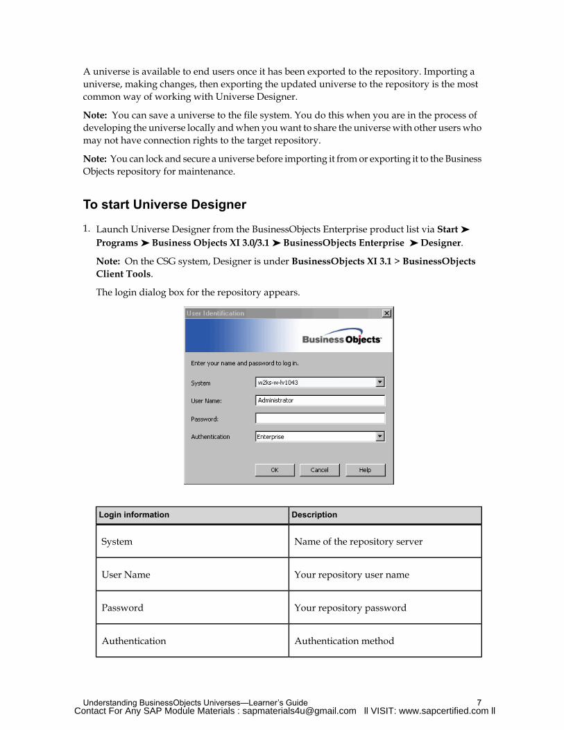
To start Universe Designer
1. Launch Universe Designer from the BusinessObjects Enterprise product list via Start ➤
Programs ➤ Business Objects XI 3.0/3.1 ➤ BusinessObjects Enterprise ➤ Designer.
Note: On the CSG system, Designer is under BusinessObjects XI 3.1 > BusinessObjectsClient Tools.
The login dialog box for the repository appears.
DescriptionLogin information
Name of the repository serverSystem
Your repository user nameUser Name
Your repository passwordPassword
Authentication methodAuthentication
7Understanding BusinessObjects Universes—Learner’s GuideContact For Any SAP Module Materials : [email protected] ll VISIT: www.sapcertified.com ll

Note: This information is usually provided to you by the BusinessObjects Administrator.
Note: You can also use Universe Designer standalone. Use the authentication methodStandalone (No CMS).
2. Click theOK button.
The Universe Designer start-up screen appears, and an empty Universe Designer sessionopens. The user name and repository name appear in the title bar.
Note: Depending on options set for Universe Designer, theQuickDesignWizard can startautomatically when you start in Universe Designer. Click Cancel to close the wizard.
Using the Quick Design Wizard
When you start aUniverseDesigner session for the first time, theQuickDesignWizard appearsby default. You can use the wizard to quickly create a universe or to familiarize yourself withUniverse Designer. However, unless your data source is a very simple model, it is not anappropriate tool for creating a complete universe that responds to end-user reportingrequirements.
Once you are familiar with Universe Designer, you probably decide to disable the wizard andnot use it to design universes. All the universe design, building, maintenance information, andprocedures in this training manual are structured with the assumption that you have disabledtheQuick Design Wizard.
To deactivate the Quick Design Wizard
You can prevent the wizard from appearing automatically when you create a new universe asfollows:1. Select Tools ➤ Options. Select theGeneral tab.
2. Clear the ShowWelcome Wizard check box, and clickOK.
Note: This check box is already cleared if you have cleared the Run this wizard at startupcheck box from the Startup Wizard Welcome page.
Note: You can activate theQuick Design Wizard at any time by selecting the above checkboxes from theGeneral page of theOptions dialog box.
Importing a universe
When you import a universe, you import the latest version of the universe from the repository.The universe is copied to the local file system, and this file is opened in Universe Designer.
You can import one or more universes stored in a universe folder in the repository.
Universe Design—Learner’s Guide8Contact For Any SAP Module Materials : [email protected] ll VISIT: www.sapcertified.com ll
To import a universe
1. Select the Import command from the Filemenu.
The Import Universe dialog box appears.
2. Select a universe folder from the drop-down list.
Note: You can also import a universe by clicking the Browse button to select the universefolder location you would like to import from.
3. Click the universe name that you want to import.
This is the universe that you want to import.
Note: If you want to lock the universe, double-click the universe name. A locked universeappearswith a padlock symbol. Locking a universe prevents other designers from importingor exporting this universe. The locked universe can still be read by users and other designers.To unlock a universe, double-click it again.
4. Verify the file path for the import folder in the Import Folder box.
This location is where the universes are exported.
5. ClickOK.
Using Universe Designer module commands
There are three ways to issue commands in Universe Designer:• Menu options
• Toolbar buttons
• Right-click menus
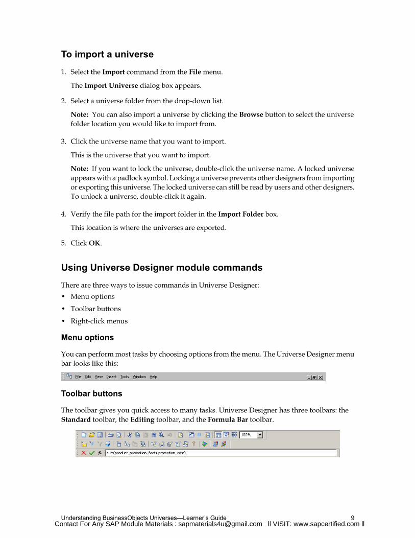
Menu options
You can performmost tasks by choosing options from themenu. The Universe Designer menubar looks like this:
Toolbar buttons
The toolbar gives you quick access to many tasks. Universe Designer has three toolbars: theStandard toolbar, the Editing toolbar, and the Formula Bar toolbar.
9Understanding BusinessObjects Universes—Learner’s GuideContact For Any SAP Module Materials : [email protected] ll VISIT: www.sapcertified.com ll
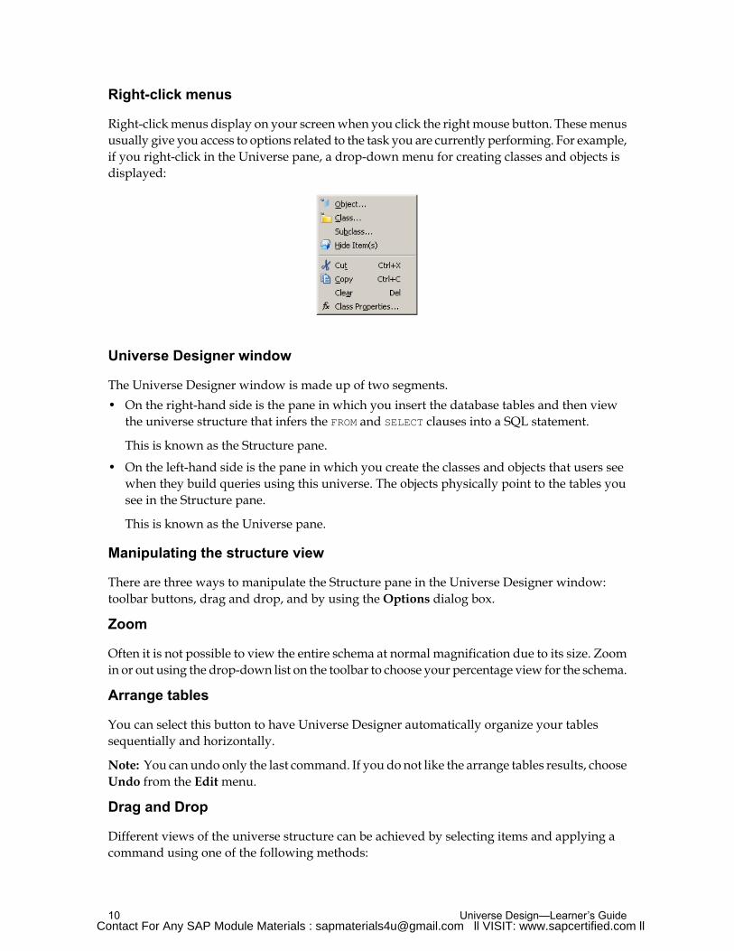
Right-click menus
Right-clickmenus display on your screenwhen you click the rightmouse button. Thesemenususually give you access to options related to the task you are currently performing. For example,if you right-click in the Universe pane, a drop-down menu for creating classes and objects isdisplayed:
Universe Designer window
The Universe Designer window is made up of two segments.• On the right-hand side is the pane in which you insert the database tables and then view
the universe structure that infers the FROM and SELECT clauses into a SQL statement.
This is known as the Structure pane.
• On the left-hand side is the pane in which you create the classes and objects that users seewhen they build queries using this universe. The objects physically point to the tables yousee in the Structure pane.
This is known as the Universe pane.
Manipulating the structure view
There are three ways to manipulate the Structure pane in the Universe Designer window:toolbar buttons, drag and drop, and by using theOptions dialog box.
Zoom
Often it is not possible to view the entire schema at normal magnification due to its size. Zoomin or out using the drop-down list on the toolbar to choose your percentage view for the schema.
Arrange tables
You can select this button to have Universe Designer automatically organize your tablessequentially and horizontally.
Note: You can undo only the last command. If you do not like the arrange tables results, chooseUndo from the Editmenu.
Drag and Drop
Different views of the universe structure can be achieved by selecting items and applying acommand using one of the following methods:
Universe Design—Learner’s Guide10Contact For Any SAP Module Materials : [email protected] ll VISIT: www.sapcertified.com ll

• Double-clicking
• Dragging and dropping
• Right-clicking
For example:
ActionProcedure
Click the header of the table.To mark a single table
Click it.To mark a join
Ctrl-click the header of each table (or join)you want to highlight.To mark more than one table or join
Ctrl-A.To mark all tables and joins
Click the header of the table and drag anddrop the table to the desired position.To move a table
By default, the table header and a specifiednumber of its columns are shown for all
To roll up a table
tables contained in the universe Structurepane. This view can be altered for anindividual table by double-clicking the tableheader.
Double-click once to roll up a table so thatonly the header is shown. Double-click twiceso that only the table header and key columnsare shown.Double-click three times to returnto an unrolled view of the table.
If the view of a table does not show all thecolumns contained within that table, this isTo view the columns of a table signified by three dots at the bottom of thetable.
Click the header of the table; a scroll barappears on the right of the table.To view the remaining columnsAlternatively, place the pointer on the bottommargin of the table and a double-headed
11Understanding BusinessObjects Universes—Learner’s Guide

ActionProcedure
arrow appears. You can then drag the bottommargin down to expand the number ofcolumns shown in the table.
To achieve this the table header must not behighlighted.
Right-click the table header and choose theView Table Values option.
To gain a partial view of the data content ofthe table
Right-click the column required and choosethe View Column Values option.
To view the data values for a single column By default, data is only displayed for the first100 rows of the table. This number can beexpanded or reduced using the Tools ➤
Options ➤ Database tab.
Right-click the table header (or structuresegment background if youwant the number
To view the number of rows for a table in thedatabase
of rows for all tables) and then choose theNumber of Rows in Table option.
If you are front ending a large database, thismay not be advisable due to the time it takesto process.
Saving and exporting a universe
Regularly save your universes during a work session. When you save a universe, UniverseDesigner stores it as a file with a .unv extension in your local file system. This is usually auniverse folder in the BusinessObjects installation path. Any changes you have made to theuniverse file are saved locally but are not propagated to the universe version in the repositoryuntil you choose to export it.
When you export the universe, the updated version is saved on the local file system, but it iscopied to the BusinessObjects repository as well. This version is then available to end usersconnecting to the universe.
It is alsomade available to other universe designerswho are authorized by the BusinessObjectsAdministrator to access it.
Regularly save your changes to a universe locally. When you have finished updating theuniverse, export the latest saved version to the repository.
Universe Design—Learner’s Guide12
If you choose to browse to a copy of that universe file on your local file system and open itdirectly in Universe Designer, the file may not be the latest version of the universe. If youwantto make changes to a universe that has already been exported to the repository, do not open auniverse file directly using File ➤ Open menu. Instead, use File ➤ Import to ensure that youare viewing the most recent version. Make your modifications and export your universe againto make your changes available in the repository.
Universe file names as identifiers
The universe name can be different from the .unv file name.
When you use Save As to save the universe under a new name, the new universe is notassociated in the repository. You must export the new universe to the repository to create aversion of the new universe.
You can use the following methods to save a universe:1. Select File ➤ Save from the menu bar.
2. Click Save.
3. Press Ctrl+S on the keyboard.
Do not save two different universes with the same file name. This leads to conflicts when youattempt to export these universes to the repository.
Saving a universe definition as PDF
You can also save the universe information in Adobe Portable Document Format (PDF). Thisallows you to save to a PDF file with the same attributes that are defined for printing purposes.
Note: You can view the default attributes by selecting the Tools ➤ Optionsmenu and selectingthe Print/PDF tab.
The attributes that you can print or save to a PDF file include:• General information: Parameters, linked universes, and the graphical table schema.• Component lists: Lists of components in the universe including objects, conditions,
hierarchies, tables, joins, and contexts.• Component descriptions: Descriptions for the objects, conditions, hierarchies, tables, joins,
and contexts in the universe.
Saving these attributes as a PDF filemay be helpful for troubleshooting ormaintenance purposes.
To save universe information as a PDF file
1. In Universe Designer, open, or import the universe you want to save as a PDF file.
2. Select File ➤ Save As.
3. Select Portable Document Format (PDF) from the Save As drop-down list.
4. Click Save.
13Understanding BusinessObjects Universes—Learner’s GuideContact For Any SAP Module Materials : [email protected] ll VISIT: www.sapcertified.com ll
Giving all users access to a universe
If you want to make a universe available to universe designers who may not have access toyour Central Management Server (CMS), you must save the universe with an unsecuredconnection.
To make a universe accessible to all Universe Designer users
1. Verify that the universe that youwant tomake available to all users does not have a securedconnection. To save a universe for all users, a shared or personal connection is required.
Note: Secured connections are required to export universes to the repository. If a universehas a secured connection, select or create a new personal or shared connection.
2. Select File ➤ Save As.
3. A File Save dialog box appears.
4. Select the Save For All Users check box.
5. ClickOK.
Activity: Viewing a universe in Universe Designer
Objective
• Open a universe and identify universe elements in Universe Designer
Instructions
1. Open Universe Designer.
2. In Universe Designer, click File ➤ Import. Browse to the eFashion.unv sample universefile in the location specified by the instructor.
3. Explore the menu options, toolbar buttons, and right-click drop-down menus.
4. Select View ➤ Toolbars, and ensure that all three toolbars are selected.
5. Zoom to 125% (type directly into the field instead of using the drop-down list).
6. Click View ➤ Arrange Tables to automatically organize tables.
7. Click View ➤ List Mode to list all tables, joins, and contexts.
8. Click the Article_Color_Lookup table in the Tables list and to see it highlighted in thestructure below.
9. Select Tools ➤ Options and click theGraphicsmenu tab.
10.Select the Show row count check box, and clickOK.
11.Right-click theArticle_Color_Lookup table to view the number of rows in the table (Refreshrow count for all tables).
Universe Design—Learner’s Guide14Contact For Any SAP Module Materials : [email protected] ll VISIT: www.sapcertified.com ll

12.Right-click the Article_Color_Lookup table to view a sample of the table values.
13.Open the Product class to view the objects it contains.
14.Double-click the Color object (notice the name, description, and select fields).
15.Close the universe.
15Understanding BusinessObjects Universes—Learner’s GuideContact For Any SAP Module Materials : [email protected] ll VISIT: www.sapcertified.com ll

Using the universe development cycleUniverse development is a cyclical process that includes planning, designing, building,distribution, and maintenance phases. Use Universe Designer to design and build a universe.However, the usability of any universe is directly related to how successfully the other phasesin the development cycle interact with each other.
After completing this unit, you will be able to:
• Use the universe development cycle
The universe development cycle process
The universe development cycle presents an overview of a universe designing methodologythat you can use to plan and implement a universe development project.
The diagram below outlines the major phases in a typical universe development cycle:
The analysis of user requirements and design are the most important stages in the process.Users must be heavily involved in the development process if the universe is going to fulfilltheir needs both with the business language used to name objects and the data that can beaccessed.
Implementationwill be successful if the first three stages are carried out properly. It is advisableto spend 80% of the time allocated to the development of a universe on the first three stages:• Preparing.
• Analyzing.
• Planning.
Universe Design—Learner’s Guide16Contact For Any SAP Module Materials : [email protected] ll VISIT: www.sapcertified.com ll

If you have spent the appropriate amount of time in laying the foundation for your universe,the remaining 20% of the time spent actually using Universe Designer to build your universewill be much more productive.
Preparation phase
During the preparation phase, the scope of a BusinessObjects universe is defined. The productionand development architectures are identified and reviewed. Project teams are assembled andthe initial task plan is defined.
Identify universe scope
The definition and communication of project scope eliminates risk associated with deployingthe universe to pilot users during the Implementation phase. The scope is defined in terms ofintended functionality of the universe. Identification of target users of the universe also helpscreate a shared understanding of project objectives.
Key managers should be involved in the scoping process. Once formulated, the objectives ofthe project are communicated to everyone involved, directly or indirectly.
Build a project team
In designating the team members, individuals must be chosen to fill the following roles. Oneperson may fill multiple roles.
TaskRole
Usually the individual funding the project. The project sponsormakes any final decisions regarding scope or unresolvable issues.Sponsor
The project leader develops the project plan, assigns resources,tracks, and reports on progress.Project Leader
Individual who gathers requirements in the form of candidateobjects.Analyst
An individual familiar with the data structures.Data Expert
Provides ongoing “business” perspective for developers.Key User
17Understanding BusinessObjects Universes—Learner’s Guide

TaskRole
Users who work with the universe during the universe build anddevelopment phase.Pilot Users
An individual with BusinessObjects experience who is not part ofthe development process performs a technical review of the finalproduct.
QA Reviewer
Inmost cases, a single person is responsible for the bulk of thework, filling the roles of Analyst,BusinessObjects Administrator, and Data Expert.
In designing and building the universe, this personmaintains a relationshipwith the KeyUser,who should also be one of the Pilot Users.
This developer usually reports to a Manager or IS Director, who serves as Project Leader. TheLeader maintains a close relationship with the Sponsor.
Other roles that will be impacted by the project include theDatabaseAdministrator, the SystemAdministrator, and the Data Administrator.
Adopt standards
Standards for the components of a BusinessObjects universe helps to guarantee consistencyand stability in the final product. During preparation, the team adopts a set of standards forBusinessObjects components. Standards can be specified for:• Universe names.• Object definition guidelines.• Names for objects.• Class names.• Alias names.• Help text.
The standards may be revised during the course of the first universe development project asthe team becomes more familiar with the product.
Conduct a meeting
Communicate the preparation phase strategy in a meeting. This is your opportunity to gatherall interested parties (developers, users, the sponsor) to ensure that everyone understands thescope of the endeavor.
Universe Design—Learner’s Guide18

You can use thismeeting to demonstrate BusinessObjects products and to help set expectationsof the user community.
Analysis phase
The primary objective of analysis activities is to identify user requirements for the ad hoc queryenvironment.
These requirements are captured in the form of candidate classes and objects.
Identify candidate objects
There aremany places to look for candidate objects. The best way to identify them is by talkingto the end users. When interviewing end users, the type of questions to ask are: “What type ofinformation do you need to do your job?”, “How do you know you are doing well?”, “Howdoes your boss know you are performing well?”, or “What kind of information do others askyou for?”
As users answer these questions, document their answers in terms of class and objectrequirements. For example, if a user states, “We need to retrieve information on employees bydepartment andhire date” youhave identified a potential class (“information about employees”)and an object or two (“department” and “hire date”).When you identify a potential class, probefor objects. For example, “What kind of information about employees do they want?”
Candidate classes and objects can also be identified by reviewing existing reports.
Document your classes and objects. For example:
SourceDescriptionNameType
Interview #1Information on a customer, includinglocation, credit ratings, and shippingpreferences.
CustomerClass
Interview #3, #4This object can be combinedwith dateranges, customers, and/or productsto provide meaningful measures.
Total
RevenueObject
(Measure)
You should also try to document the qualification of objects (dimension/detail/ measure) andany potentially identified hierarchies.
Relational modeling versus multi-dimensional modeling
19Understanding BusinessObjects Universes—Learner’s Guide
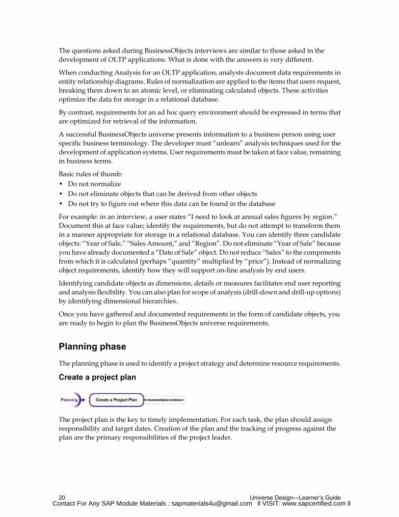
The questions asked during BusinessObjects interviews are similar to those asked in thedevelopment of OLTP applications. What is done with the answers is very different.
When conducting Analysis for an OLTP application, analysts document data requirements inentity relationship diagrams. Rules of normalization are applied to the items that users request,breaking them down to an atomic level, or eliminating calculated objects. These activitiesoptimize the data for storage in a relational database.
By contrast, requirements for an ad hoc query environment should be expressed in terms thatare optimized for retrieval of the information.
A successful BusinessObjects universe presents information to a business person using userspecific business terminology. The developer must “unlearn” analysis techniques used for thedevelopment of application systems. User requirementsmust be taken at face value, remainingin business terms.
Basic rules of thumb:• Do not normalize• Do not eliminate objects that can be derived from other objects• Do not try to figure out where this data can be found in the database
For example: in an interview, a user states “I need to look at annual sales figures by region.”Document this at face value; identify the requirements, but do not attempt to transform themin a manner appropriate for storage in a relational database. You can identify three candidateobjects: “Year of Sale,” “Sales Amount,” and “Region”. Do not eliminate “Year of Sale” becauseyou have already documented a “Date of Sale” object. Do not reduce “Sales” to the componentsfromwhich it is calculated (perhaps “quantity” multiplied by “price”). Instead of normalizingobject requirements, identify how they will support on-line analysis by end users.
Identifying candidate objects as dimensions, details or measures facilitates end user reportingand analysis flexibility. You can also plan for scope of analysis (drill-down and drill-up options)by identifying dimensional hierarchies.
Once you have gathered and documented requirements in the form of candidate objects, youare ready to begin to plan the BusinessObjects universe requirements.
Planning phase
The planning phase is used to identify a project strategy and determine resource requirements.
Create a project plan
The project plan is the key to timely implementation. For each task, the plan should assignresponsibility and target dates. Creation of the plan and the tracking of progress against theplan are the primary responsibilities of the project leader.
Universe Design—Learner’s Guide20Contact For Any SAP Module Materials : [email protected] ll VISIT: www.sapcertified.com ll

Plan the BusinessObjects architecture
Technical architecture requirements may have been looked at in general in the preparationphase. A review of the technical architecture should take place during the planning phase ofthe project. Items to review include:
Identify resources required to support a universe developmentenvironment.
Developmentenvironment
Identify resources required for a universe production environment.Productionenvironment
Review required computing resources for developer and userworkstations.Computers
Ensure infrastructure is in place to support connectivity betweenusers/developers and the repository and data stores, includingConnectivity appropriate middle-ware to support communication between clientsand servers.
Identify planned configuration for client software. Ensure appropriateresources are available.Configuration
Initiate a first look at security requirements.Security
Develop support policy for when the universe goes into production.Support plan
Identify procedures for the request, review, approval, andimplementation of changes to the universe when in production.
Changemanagement plan
Plan for a user training program.Training plan
Implementation phase
The implementation phase can be split up into two stages:1. Designing the schema.
2. Building the universe.
21Understanding BusinessObjects Universes—Learner’s GuideContact For Any SAP Module Materials : [email protected] ll VISIT: www.sapcertified.com ll

Implementation phase 1: schema design
The first task during schema design is to determine and document the data source for eachcandidate object. If requirements were gathered in a tabular format, add a column to the tablewhere you can indicate the SQL fragment and source tables that are used to retrieve the object.
SourceDescriptionSQL fragmentNameType
Interview#1
Information on a customer,including location, creditratings, and shippingpreferences.
CustomerClass
Interview#3,4
This object can be combinedwith date ranges, customers,and/or products to providemeaningful measures.
SQL:
sum(order_lines.quantity*
products.price)
Source Tables: Order_Lines,Products
TotalRevenue
Object(Measure)
Any candidate classes that were captured as general requirements without specific objectsmust be expanded now. For example, suppose there was a candidate class called “Customer”and the specific objects within this class were not identified. During the schema design stage,the developer must “fill out” this class. The developer might fill it out based on knowledge ofthe business by including all columns from one or more tables, or the developer might go backto users for more detail.
There are several ways that objects can be mapped to enterprise data. Simple objects map backto a single column in the database. An example would be "Customer First Name", which mapsback to the First_Name column in the Customers table. Complex objects make use of SQL tomanipulate data that comes from one or more columns. For example, a "Customer Full Name"object might connect the First_Name and Last_Name columns from the Customers table.
Aggregate objects involve SQL GROUP functions. Counts, sums, and averages are all aggregateobjects. The Total Revenue object is an aggregate object; it uses the SQL SUM function.
Plan for object qualifications and drill-down functionality
As you design the universe, youmust complete the process you began during analysis. Identifyeach object as a measure, a dimension or a detail. For each detail object, identify the dimensionit is associated with.
Universe Design—Learner’s Guide22Contact For Any SAP Module Materials : [email protected] ll VISIT: www.sapcertified.com ll

Similarly, you need to identify hierarchies within your dimensions. These hierarchies laterenable users to “drill-down” and “drill-up”.
Design a table diagram
Now that the objects are mapped back to data sources, the developer reviews all the objectsand produces a table-diagram of the database objects that support the universe. Joins betweenthe tables are then added to the diagram. The table diagram is a valuable tool for resolvingloops and SQL traps in the model. It also becomes an important reference for developers.
Note: This diagram design is usually done on paper, however this can be created directly inthe BusinessObjects Universe Designer software.
Tip: If you find that you have documented a vast amount of classes and objects based on userrequirements you may consider designing schemas that can be used to build:1. Multiple universes which cater to a specific function within the business, reducing the
complexity and amount of classes and objects.
2. Multiple universes specific to a business function, as this prevents users from creating queriesthat can span the spectrum of the business.
Revise objects and table diagram
Once loops and SQL traps are resolved, the design of some objects require modification. Anyobject based on a table that was replaced by an alias are updated. Consult your table of objectscreated in the preparation phase for such objects.
Note: If you are already using Universe Designer for the schema design you can view a table’sassociated objects to identify which objects require changes.
Some objects may be applicable in the context of more than one of the aliases; these objects willbe split intomultiple objects.Make sure that object namesmake it clearwhat each one represents.
Review join strategy
Where table relationships are optional, the type of join to use must be chosen carefully. Theuse of standard (or inner) versus outer joins impacts the results of user queries. Using thewrongtype of join may provide results that are not what users expect.
In SQL, a standard join between two tables returns only rows where both tables meet the joincriteria. If one of the tables has no corresponding row in the second table, its data is not returned.
An outer join tells the database processing the SQL query to substitute a “null” row if one ofthe joined tables has no corresponding row in the other table. With an outer join, informationin one table that does not have corresponding data in the second table is returnedwith “blanks”in columns from the second table.
The developer must review join possibilities with a key user wherever optional relationshipsexist. The chosen solution should produce results that users are most likely to expect.
23Understanding BusinessObjects Universes—Learner’s Guide

Identify allowable object usage
The developer may identify certain objects that should not be used in qualifications by endusers. Certain complex objectsmay not be usable in qualifications for technical reasons, or theremay be performance considerations.
Determine security approach
Security requirements must also be addressed during the Implementation phase. Solutions tosecurity requirementsmay involve complex object definition, reliance ondatabase-level security,use of BusinessObjects access levels (public, private, controlled), restriction sets, or thedevelopment of multiple universes. Chosen solutions may impact the database administratorand developers.
Implementation phase 2: building the universe
Once the schema design stage is complete, the development team is ready to begin using theBusinessObjects Universe Designer software to build the universe.
Tip: Remember that it is better to have several smaller less complex universes than one largeuniverse. This reducesmaintenance, avoids potential security impacts andwill improve overallusability.
Pilot users then begin to use the universe. They provide feedback to developers who refine theuniverse until build is completed.
Build the universe
The BusinessObjects Universe Designer software is used to actually build the universe. Thedeveloper must:• Name the universe.• Set up the universe parameters and connect to the relevant data source.• Create aliases and contexts as identified in the schema design.• Create joins as identified in the schema design.• Create classes, subclasses and objects as identified in the schema design.• Define objects as dimensions, details, or measures.• Define hierarchies.• Define lists of values and help text.• Define conditions and implement user security, where applicable.
Universe Design—Learner’s Guide24

Supply prebuilt queries and reports
During the build stage, the team may identify certain queries and reports that are of value tothe entire enterprise. Created at anytime throughout the build, these queries and reports arere-checked after the universe is finalized to ensure that objects used have not been renamed orremoved. They are then exported to the repository so that they are available to all users.
Testing phase
The pilot testing and refinement phase follows universe design implementation.
Once an initial universe is built, it is deployed to the pilot users. These users work with theuniverse and provide feedback to the developers.
Types of feedback include:• Better names for classes and objects.• Objects not in the universe that should be added.• Objects that can be removed.• Better ways to organize objects (for example, move an object from one class to another,
reclassifying a dimension as a detail, and so on).• Objects or queries that do not behave as expected.
Based on this feedback, the universe is modified. The modified universe is made available tothe pilot users for further evaluation. The testing phase can also address potential performanceissues. As a developer you can look at implementing performance enhancements to the universe.
Quality assurance
After the build is finalized, the universe is reviewed for quality assurance.
An independent reviewer makes the following checks:• Corporate standards for universe, object, class, and alias naming are followed.• Objects are only defined with tables that are referenced in the SELECT or WHERE clauses• Objects return results without syntactic error.• Objects return intended business results.• Objects are correctly classified as dimensions, details or measures.• Defined hierarchies make sense.• Objects have help text.• Aliases are used appropriately.• Join syntax and foreign keys are accurate.• Standard and outer joins are used appropriately.
These checks are best made by an individual who was not part of the development of theuniverse, guaranteeing an objective perspective. Any issues that are identified are reported tothe developers for correction and review.
25Understanding BusinessObjects Universes—Learner’s Guide

Deployment phase
The universe has been built, and has passed all quality assurance checks. It is now ready fordeployment.
The final deployment of the universe cannot begin until any architectural issues identifiedduring planning phase have been addressed. These issues include the establishment of userconnectivity, planning the installation configuration, preparation of a training program, andidentification of support and change management processes.
Architecture
Architectural considerations identified during the planning phase are reviewed. Any issuesthat have not been resolved delay the deployment phase.
Production environment
The production environment has been set up in accordance with the architecture and securityplans identified during preparation and planning. The universe ismodified to access data fromproduction systems, rather than from development systems and is exported to the productionrepository.
Granting user access
Any database accounts that are required for BusinessObjects users should be created by thedatabase administrator. These accounts should be given appropriate access privileges to thedata objects used by the universe.
Users are also added to the Central Management System (CMS) and granted access to theuniverse.
Conduct training
The release of the BusinessObjects universe to production users is coordinated with systemanddatabase administrators as appropriate. The user trainingprogram is executed in conjunctionwith the roll-out of the universe. Without appropriate training, users will not derive benefitsfrom BusinessObjects, regardless of the quality of the universe.
Universe Design—Learner’s Guide26
Prepackaged solutions
If you are designing a universe for Business Objects developers for developing precreated/prepackaged reports, then the following items should be taken into consideration:• Predefine all filters and calculations that are used in standarddocuments, to remain consistent
throughout.• The universe can covermore than one business function, to allow cross functional reporting.
Precreated reports tend to cross reference reports against different business functions. Theuniverse, therefore, has to covermultiple business functions to provide end-to-end businessreporting.
Activity: Planning a universe
Objective
• Use the first three stages of the universe development cycle.
Instructions
1. Launch the Planning_universe_activity.html file, from the course resources, to familiarizeyourself with the universe development cycle and to complete the activity questions.
2. Use this checklist of questions you need to ask when you begin designing a universe:• What are the target data sources for your universes?
• What is the schema/structure of each of these data sources?
• Do you know the contents of each of the tables?
• Do you know how each of the tables are interrelated?
• Are you familiar with all of the necessary joins?
• Are you familiar with the cardinality of each of these joins?
• Have youprocureddatabase schemas from the database administratorswho administratethe data sources?
• Are you familiar with your different user populations and how they are structured?
• Do you know what standard reports are required?
27Understanding BusinessObjects Universes—Learner’s GuideContact For Any SAP Module Materials : [email protected] ll VISIT: www.sapcertified.com ll

• Do you know what the users' ad hoc information needs are?
• Are you familiar with their business terminology and formats?
• Have you considered how many universes need to be created to address users' needs?
• Have you considered how long universe development may take?
• Have you considered which universes should be developed before others?
• Have you considered who should test your universes for you?
• Have you considered how data sources and/or user requirements may change overtime?
• Do you already have all of the information necessary to implement your universes?
Universe Design—Learner’s Guide28Contact For Any SAP Module Materials : [email protected] ll VISIT: www.sapcertified.com ll

Quiz: Understanding BusinessObjects universes1. What are the two main panes in Universe Designer?
2. What are the three ways to issue commands in Universe Designer?
3. Where can you define what specific information about the universe gets printed?
29Understanding BusinessObjects Universes—Learner’s Guide

Lesson summaryAfter completing this lesson, you are now able to:
• Define BusinessObjects universe concepts• Use the universe development cycle
Universe Design—Learner’s Guide30

Lesson 2Creating the Course Universe
Lesson introductionThis lesson introduces you to the database that is used in this course. It teaches you how tocreate a new universe and define a connection from the universe to the course database.
To create a new universe and maximize its potential, it is necessary to learn about parameters.Parameters allow you to set the structure of your universe, including setting up a databaseconnection.
After completing this lesson, you will be able to:
• Describe the course database and universe• Create the course universes
31Creating the Course Universe—Learner’s Guide
Describing the course database and universeIn order to create a BusinessObjects universe, you must first be familiar with the data andstructure of the database to which the universe is connected. You also need to fully understandthe users’ reporting requirements.
After completing this unit, you will be able to:
• Understand the database used during this course• Know the specifications of the universes built during this course
The course database
During this course, you are going to build universes to report on a database for a fictional carsales and rentals organization called Prestige Motors. The database has the followingcharacteristics:• There are three showrooms, two in the US and one in the UK.
• Each showroomhas the franchise for a number of different carmakers, who allmanufacturea number of different models, available in a range of colors.
• Customers may either rent or buy cars.
• Customers usually rent or buy from the showroom in their own country but this is notalways the case.
• The database contains data for two financial years 2003/2004 and 2004/2005. Each yearbegins on April 6 and ends on April 5 in the subsequent year.
• Information about employees who work within the organization is also available in thedatabase.
• There are summary tables for quarterly and annual revenue and numbers to speed upqueries.
• The data is stored in a SQL Server 2005 database.
• Connections to the database are made using OLE DB.
Assumptions
• There has been no inflation over the different years for which data is held.
• There is no stock data. All manufacturers are able to supply on demand.
• Users in all countries use the same currency (the US dollar).
• No new models have been brought out during the period.
Analysis of reporting requirements
Following an analysis of the company’s reporting needs, the following specification has beenidentified.1. Ad hoc reports are required on models.• These are required to list the cars for sale and rent.
Universe Design—Learner’s Guide32Contact For Any SAP Module Materials : [email protected] ll VISIT: www.sapcertified.com ll

• Such reportsmay include the following:manufacturer,model, trim, engine size, availablecolors, and, sale/rental price.
• Reports may be grouped by price range and style (for example, sport, or estate.)• These reports are used to show potential customers model availability and for general
management reporting.
2. A report is required which lists the showrooms, their location and which manufacturersthey have a dealership agreement with.
3. Ad hoc reports are required on car sales.• These are required to list car, sale, and customer details.• Reportsmaybe grouped according to customer, showroom, sale,model, andmanufacturer
dimensions.• These reports are used to analyze results at all levels from sales specific details to general
high-level reports such as sales revenue per annum, per showroom, by manufacturer,or by car.
4. Ad hoc reports are required on car rentals.• These are required to list car, rental, and customer details.• Reports may be grouped according to customer, showroom, rental, model, and
manufacturer dimensions.• These reports are used to analyze results at all levels from specific rentals details to
general high-level reports such as rentals revenue per annum, per showroom, bymanufacturer, or by car.
• Reports related to 2, and 3 are used by sales staff, finance department staff, andmanagers.
5. Ad hoc reports on employees.• The employee reports are only be available to Managers and the Personnel Department
staff.• Therefore, a different universe is used so that only these people have access to this data.
Note: Most users are required to run reports on both sales and rentals.
Development plan
The remainder of this course is spent developing universes for this imaginary deployment. Inaccordance with the iterative approach, the development is phased as indicated below.1. Design and develop a universe which enables end users to build reports which meet
requirements 1 (model reporting) and 3 (sales reporting). The universe needed to do thiscan be regarded as relatively simple to create.
2. Extend the universe to meet reporting requirements 2 (franchise reporting) and 4 (rentalreporting). This requires the introduction of loops, chasm and fan traps into the universestructure which need to be resolved. This constitutes a fairly complex universe structure.
33Creating the Course Universe—Learner’s GuideContact For Any SAP Module Materials : [email protected] ll VISIT: www.sapcertified.com ll

3. Further extend the universe to refine and enhance the universe for end users by introducingconditions, LOVs, and hierarchies for drilling.
4. Design and develop a universe for end users that enables them to build reports which meetrequirements 5 (ad hoc reporting on employees).
Universe Design—Learner’s Guide34

Creating the universeIn this unit, you begin to create the course universe, based on the analysis of businessrequirements and the development plan.
After completing this unit, you will be able to:
• Create a new data source name• Create a new connection in Universe Designer• Create a new universe• Describe the universe parameter settings
Setting the database connection
In order to create a universe, you need to create a BusinessObjects connection to the databaseyou intend to use.
A connection is a named set of parameters that defines how a Business Objects applicationaccesses data in a database file. A connection links Business Objects querying tools to yourmiddleware. You must have a connection to access data.
The BusinessObjects connection contains all pertinent information for how to connect to thetarget database (for example: data access driver (middleware), connect string, connection type,and advanced connection parameters).
If you are building several universes to front end the same database, then the connection mayalready exist. Therefore, you only have to select it from the available connections. However, ifthe connection does not exist, you have to create one.
Data access drivers
A data access driver is the software layer that connects a universe to your middleware.
Data access drivers are shipped with Business Objects products. There is a data access driverfor each supported middleware. When you install Universe Designer, your data access keydetermines which data access drivers are installed.
When you create a new connection, you select the appropriate data access driver for the relationaldatabase management system (RDBMS) middleware that you use to connect to the targetRDBMS.
The types of databases supported through data access drivers are:• IBM DB2• Informix• Microsoft SQL Server• Oracle• Red Brick• Sybase• NRC (Teradata)
35Creating the Course Universe—Learner’s Guide

• Hyperion• Generic ODBC
With the new XI architecture, connections can now be made to MS Analysis Services 2000,MySQL, and SAP.
ODBC connection drivers
Open Database Connectivity (ODBC) is Microsoft's strategic interface for accessing data in aheterogeneous environment of relational and non-relational database management systems.An ODBC Driver can be the "back end" for a DBMS (Database Management System) serverenvironment. Any ODBC client can access any DBMS for which there is an ODBC Driver, forexample SQL Server, Oracle, AS/400, Foxpro, Microsoft Access, or any DBMS for which anODBC driver exists.
Note: Connections to the database can bemade usingODBC aswell as OLEDB (Object Linkingand Embedding, Database).
OLE DB connectivity
OLE DB (Object Linking and Embedding, Database) is an API, based on a set of interfacesimplemented using the Component Object Model (COM), designed byMicrosoft for accessingdifferent types of data stored in a uniform manner. These interfaces support the amount of
Universe Design—Learner’s Guide36Contact For Any SAP Module Materials : [email protected] ll VISIT: www.sapcertified.com ll

DBMS functionality appropriate to the data store, enabling the data store to share its data. OLEDB was designed as a higher-level replacement for, and successor to, ODBC, extending itsfeature set to support a wider variety of non-relational databases, such as object databases andspreadsheets that do not necessarily implement SQL.
OLE DB is part of the Microsoft Data Access Components (MDAC) stack, a group of Microsofttechnologies that interact together as a framework allowing programmers a uniform andcomprehensive way of developing applications for accessing almost any data store.
To create an ODBC connection for SQL Server 2005
Note: This example describes how to create an ODBC connection. Direct connections aresupported for certain database vendors, therefore the ODBC setup is not always required.
SQL Server 2005 is the database used for this course. For this course ODBC is used to connectto the SQL Server 2005 database.
Note: Steps outlined below apply to any version of SQL Server.
1. Navigate to theODBC Data Source Administratorwizard.
• Start ➤ Programs ➤ Administrative Tools ➤ Data Sources (ODBC).
• Start ➤ Settings ➤ Control Panel ➤ Administrative Tools ➤ Data Sources (ODBC).
2. Click the System DSN tab.
3. Click Add.
4. Scroll down to select the SQL Server driver, and then click Finish.The Create a New Data Source to SQL Server page opens.
5. In theName box, type a name that identifies the database you want to connect to.
6. In the Server box, type or select the name of the server on which SQL Server is installed.
7. ClickNext.
8. For the authentication, select the appropriate method for SQL Server to authenticate thelogin ID.Depending on the selected option, type in the requiredWindowsor SQLServer authenticationuser name and password.
9. Select theChange the default database to check box, and then select the database to connectto from the drop-down list.
10.ClickNext, and then click Finish.
11.Click Test Data Source.
You should get the message TESTS COMPLETED SUCCESSFULLY.
If you don’t get this message, review your steps and verify the added authenticationcredentials.
37Creating the Course Universe—Learner’s GuideContact For Any SAP Module Materials : [email protected] ll VISIT: www.sapcertified.com ll

12.ClickOK until you can close the Administrative Toolswindow.
To define a connection in Universe Designer using an ODBC DSN
1. In Universe Designer, select Tools ➤ Connections.
2. Click the Add button in the Connections list.
TheWelcome page of the Connection Wizard appears.
3. ClickNext.
TheDatabase Middleware Selection page appears. It lists the database and middlewarethat correspond to your data access driver key.
4. Select the connection type from the Connection Type drop-down list.
Note: In order to deploy a universe to the BusinessObjects repository, youmust define thisconnection type as "Secured".
5. In the Connection Name field define a name for the connection.
You can enter up to 35 characters.
6. Expand the + box for the target database for the connection.
The supported middleware for that database appears in the expanded area.
7. Expand the + box for the target middleware for the connection.
The data access drivers for the middleware appears.
8. Select the ODBC driver name and clickNext.The Login Parameters page appears.
9. Select the required authentication mode.
10.In the User name and Password fields enter the database login credentials.
11.In the Data source name field, select the appropriate data source for the database you areconnecting to.
12.Once you have entered this information, clickNext.
13.In the Configuration Parameters page, apply the required parameters or keep the defaultvalues selected. ClickNext.
14.In the Custom Parameters page, apply the required parameters or keep the default valuesselected. Click Finish.
15.In theWizard Connection dialog box, click the Test button to test the connection.
If the connection is valid, a message dialog box appears indicating that the connection iscorrect. If you receive an error message, check that you entered all the parameters correctly.If the error persists, refer to the section of your RDBMS documentation relating to errormessages.
Universe Design—Learner’s Guide38Contact For Any SAP Module Materials : [email protected] ll VISIT: www.sapcertified.com ll

16.Click Finish to exit the wizard.
Note: Avoid creating two different secured connections with the same name. For example,one connection named "Status" and the other named "status". This may lead to a conflict inthe repository.
To define a connection in Universe Designer using OLE DB
1. In Universe Designer, select Tools ➤ Connections.
2. Click the Add button in the Connections list.
TheWelcome page of the Connection Wizard appears.
3. ClickNext.
TheDatabase Middleware Selection page appears. It lists the database and middlewarethat correspond to your data access driver key.
4. Select the connection type from the Connection Type drop-down list.
Note: To deploy a universe to the BusinessObjects repository, you must define thisconnection type as "Secured".
5. In the Connection Name field, type the appropriate data source name for the database towhich you are connecting.
You can enter up to 35 characters.
6. Expand the + box for the target database for the connection.
The supported middleware for that database appears in the expanded area.
7. Expand the + box for the target middleware for the connection.
The data access drivers for the middleware appears.
8. Select the OLE DB driver name and clickNext.The Login Parameters page appears.
9. Select the required authentication mode.
10.In the User name and Password fields enter the database login credentials.
11.In the Server field, select or enter the appropriate server name on which the database youare connecting to is installed.
12.In the Database field, enter the name of the database to which you are connecting.
13.Once you have entered this information, clickNext.
14.In the Configuration Parameters page, apply the required parameters or keep the defaultvalues selected. ClickNext.
15.In the Custom Parameters page, apply the required parameters or keep the default valuesselected. Click Finish.
39Creating the Course Universe—Learner’s Guide
16.In theWizard Connection dialog box, click the Test button to test the connection.
If the connection is valid, a message dialog box appears indicating that the connection iscorrect. If you receive an error message, check that you entered all the parameters correctly.If the error persists, refer to the section of your RDBMS documentation relating to errormessages.
17.Click Finish to exit the wizard.
Note: Avoid creating two different secured connections with the same name. For example,one connection named "Status" and the other named "status", which may lead to a conflictin the repository.
Viewing, modifying, and deleting available connections
You can view all available stored connections in the Connections List .
Using theWizard Connection, you can edit existing connections, or create new ones.
This list displays all the connections available to the designer, regardless of the universes. Thecurrent universe may be based on a SQL Server database, but you can add a new connectionto an Oracle database in this wizard. You can add, delete, and edit existing connections fromthis dialog box.
Note: You cannot modify the name of an existing connection.
To view available connections
1. Select Tools ➤ Connections.
TheWizardConnectiondialog box appearswith theConnections Listpage. This list displaysall the connections available to the designer, regardless of the universes.
Universe Design—Learner’s Guide40

2. Click Cancel to close the dialog box.
To edit a connection
1. Click Tools ➤ Connections.
TheWizard Connection dialog box appears.
2. Select the connection that requires editing from the list of available connections.
3. Click Edit.
The Login Parameters page for the connection appears.
4. Modify the login parameters or select a different data source for the connection.
5. ClickNext.
6. Modify the configuration parameters as required, and clickNext.
7. Modify the custom parameters as required, and click Finish.
8. Click the Test button to verify the modified connection.
9. Click Finish to apply the changes to the connection.
To delete a connection
1. Click Tools ➤ Connections.
TheWizard Connection dialog box appears.
2. Select the connection you want to delete from the list of available connections.
41Creating the Course Universe—Learner’s Guide

3. Click the Remove button.
A confirmation dialog box appears.
4. Click Yes.
The connection is removed from the list.
Creating a new universe
Before you can build a universe, you must first create a new universe file.
You save the new universe as a .unv file.
The new universe contains no classes and objects. You create these during the universedevelopment process by designing a table schema and then creating objects thatmap to databasestructures.
To begin creating a new universe
1. In Universe Designer, selectNew from the Filemenu.
The Universe Parameters dialog box displays:
Note: Ensure the Universe Parameters dialog box displays with theDefinition tab active.
2. In the Name field, enter a name for the universe.
3. In the Description field, enter a brief description for the universe.
This description is intended to help the end user. It needs to accurately describe the contentof the universe by using terminology the end user easily understands.
Universe Design—Learner’s Guide42Contact For Any SAP Module Materials : [email protected] ll VISIT: www.sapcertified.com ll

4. In the Connection field, select or define the data source connection.
5. Select File ➤ Save As.
6. Provide a name for the file.The universe file is saved locally as a .unv file.
Defining universe parameters
To be able to start building the universe structure, you first define a number of parameters,such as the parameters to be used to connect to the data source.
Universe parameters are definitions and restrictions that you define for a universe. Theseparameters:• Identify the universe.• Identify the database connection.• Specify the type of queries that can be run using the universe.• Set the controls on the use of system resources.
An important element of this setup process is selecting the kind of database connection youuse.
Select an existing connection or create a new one. The other parameters can be set at this pointbut are better done at a later point in the universe building process.
Identifying the universe
Each universe is identified by the following parameters:
Used byIdentifier
File system, Business Objects end-userquerying tools to reference the universeFile name
Business Objects end-user querying toolsLong name
Business Objects end-user querying toolsDescription
Central Management ServerUnique system identifier
File names
A file name is created when you save the universe. The length of the name is dependent onyour operating system maximum. Windows allows approximately 156 characters. The filename extension is .unv.
43Creating the Course Universe—Learner’s Guide
Contact For Any SAP Module Materials : [email protected] ll VISIT: www.sapcertified.com ll

The local file system is the server on which Universe Designer is installed. Your universes aresaved by default in the universes folder in your user profile path, for example: \\Documentsand Settings\<user>\Application Data\Business Objects\Business Objects
12.0\Universes\<universe>.unv
Note: Do not change the universe file name after reports have been created on that universeor the report files no longer point to the universe.
Long names
The universe long name is set in the Name field on theDefinition tab. You can enter up to 200characters and there are no character restrictions.
Universe descriptions
The universe description is an optional field. Information in this field can provide useful detailsabout the universe’s role and is viewable by end users.
Unique system identifiers
The unique system identifier is assigned by the CentralManagement System (CMS). This occurswhen the universe is exported to the repository for the first time.
Universe parameters
Universe parameters are definitions and restrictions that you define for a universe. UniverseDesigner allowsdesigners to define several different parameters using the different tabs availablein the Universe Parameters dialog box.
Note: For more detailed reference information about these parameters, refer to Chapter 2 - DoingBasic Operations, Setting Universe Parameters in the Business Objects XI 3.0/3.1 Designer’s Guide.
Universe Parameters dialog box
There are seven tabs on theUniverse Parameters dialog box that allow you to change differentparameters.
This table provides a quick snapshot of the different tabs:
DescriptionParameter
Universe name, description, connectionparameters, and information. Theseparameters identify the universe.
Definition
Version and revision information, designercomments, and universe statistics.Summary
Universe Design—Learner’s Guide44
Contact For Any SAP Module Materials : [email protected] ll VISIT: www.sapcertified.com ll

DescriptionParameter
Strategies used by the universe. A strategy isa script used to extract structural informationfrom a database.
Strategies
Limitations set for the use of systemresources.Controls
Types of queries that the end user is allowedto run.SQL
Settings defined for linked universes.Links
SQL parameters that can be dynamicallyconfigured.Parameter
Definition tab
On theDefinition tab you can set the universe name and a meaningful description. There isno character limitation. End users see these in their Business Objects querying tool when theyselect the universe.
The Connection field displays the connection name defined against the database.
45Creating the Course Universe—Learner’s Guide
Contact For Any SAP Module Materials : [email protected] ll VISIT: www.sapcertified.com ll

Select theClick here to choose storedprocedure universe option to connect to storedproceduresavailable in the data source. The available stored procedures are displayed in theTable Browser.
Summary tab
The Summary tab displays universe administration information.
DescriptionInformation
Universe creation date and the name of thecreator.Created
Date of lastmodification and the name of themodifier.Modified
Revision number indicates the number oftimes the universe has been exported to therepository.
Revision
Information about the universe for yourselfor another designer. This information is only
Commentsavailable in Universe Designer. Includesinformation about the universe for end users.
You can print the text contained in this box,which means that you can use it to track
Universe Design—Learner’s Guide46

DescriptionInformation
changesmade to the universe and bywhom,if you so desire.
List of the number of classes, objects, tables,aliases, joins, contexts, and hierarchiescontained in the universe.
Statistics
Strategies tab
A strategy is a script that automatically extracts structural information from a database or flatfile. Default strategies have two principle roles:• Automatic join and cardinality detection.
• Automatic class, object, and join creation.
Strategies are useful if you want to automate the detection and creation of structures in youruniverse based on the SQL structures in the database.
Strategies that automate the creation of universe structures are not necessarily an essential partof universe design and creation. They are useful if you are creating a universe quickly, andyouwant to usemetadata information that already exists in a database or database design tool.
However, if you are building a universe by creating objects and joins that are based onrelationships that come directly from a user needs analysis, then you probably not use theautomatic creation possibilities that this tab offers.
Built-in strategies are the default strategies that are shipped with Universe Designer. You canselect themby clicking the drop-downmenus in this strategies parameters tab. There are built-in
47Creating the Course Universe—Learner’s Guide

strategies for all supported databases, which cannot be modified. You can, however, createcustom strategies, which are known as external strategies. Built-in strategies appear by defaultbefore external strategies in the drop-down lists.
Note: The built-in strategies for detecting joins only select on matching column names, ignoringall other column names, and may create unnecessary joins.
Controls tab
On the Controls tab, you can limit the result size and execution times for queries that use thisuniverse.
The Limit execution time option allows you to restrict the execution time for any querygenerated via the universe for queries generating more than one SQL statement.
The time limit that you specify for query execution is the total execution time for a query. Ifthe query contains multiple SQL statements, then each statement is given an execution timeequal to the total query execution time divided by the number of statements. The result is thateach statement in the query has the same execution time.
If one statement requires a lotmore time than others to run, itmay not complete as its executiontime does not correspond to its allotted execution time within the query.
When you specify an execution time limit for multiple SQL statements, you need to take intoaccount the normal execution time of the single statement that takes the longest time to run,and multiply this value by the number of statements in the query.
If you set theWarn if cost estimate exceeds option, a message informs the user if the query islikely to takemore than the number ofminutes you specify here. Thismechanism is dependenton whether the database statistics are up-to-date.
Universe Design—Learner’s Guide48
Contact For Any SAP Module Materials : [email protected] ll VISIT: www.sapcertified.com ll

SQL tab
You can set controls on the types of queries that end users can build in BusinessObjects queryingtools.
You can indicate controls for the following areas of query generation:• Use of subqueries.
• Use of operators and operands in individual queries.
• Generation of multiple SQL statements.
• Selection of multiple contexts.
• Prevent or warn about the occurrence of a Cartesian product.
Note: The Multiple SQL statements for each measure option is selected by default. Accepting thisdefault value could potentially impact query performance.
49Creating the Course Universe—Learner’s Guide
Contact For Any SAP Module Materials : [email protected] ll VISIT: www.sapcertified.com ll

Links tab
Links specify dynamic links between universes related to the same database. This allows auniverse and its content to be embedded in another universe. Embedding universes optimizesmaintenance where some objects are used in many universes.
Note: Universes need to be exported to the repository before linking.
Parameters tab
Universe Design—Learner’s Guide50

In Universe Designer, you can configure certain SQL parameters that are common to mostdatabases to optimize the SQL generated. These parameters apply only to the active universe,and are saved in the .unv file.
Activity: Creating a new universe and defining its connection
Objective
• Create a new universe and define its connection to the database
Instructions
1. Start aUniverseDesigner session and log on using the credentials provided by the instructor.
2. Create a new universe calledMotors_xx, where "xx" stands for your initials.
3. Add the following description: This universe provides information on the PrestigeMotor Cars Database for Showrooms, Models sold, Rental and Sales Business.
4. Create a new OLE DB connection calledMotorsOLEDB_xx, where "xx" stands for yourinitials.
5. Save your new Motors universe via File ➤ Save As.The universe is saved in the local universe directory.
6. Create another new universe and define the following parameters:• Name = Staff_xx (Where "xx" stands for your initials.)• Description = This universe provides information on the personnel of Prestige
Cars.• Connection: MotorsOLEDB_xx (Where "xx" stands for your initials.)
Tip: Use the same connection that you created in Step 4.
7. Save your Staff universe locally using File ➤ Save As.
51Creating the Course Universe—Learner’s Guide

Quiz: Creating the course universe1. Information about universe administration appears on theUniverse Parametersdialog box.
Under which tab can you find this information?
2. Can a universe and its content be embedded in another universe?
3. If you want to distribute the completed universe to the user population using theBusinessObjects repository, which type of connection should you use?
Universe Design—Learner’s Guide52

Lesson summaryAfter completing this lesson, you are now able to:
• Describe the course database and universe• Create the course universes
53Creating the Course Universe—Learner’s Guide

Universe Design—Learner’s Guide54

Lesson 3Building the Universe Structure
Lesson introductionThis lesson describes how to add tables to the universe structure and how to customize theway you work with tables.
After completing this lesson, you will be able to:
• Populate the universe structure• Define joins in a universe
55Building the Universe Structure—Learner’s Guide

Populating the universe structureA schema is a graphical representation of a database structure. InUniverseDesigner you createa schema for the part of the database that your universe represents.
After completing this unit, you will be able to:
• Design a schema
• Add tables in the Structure pane
• Organize your view of tables
Designing a schema
The schema contains tables and joins. Objects are mapped to columns in tables that end usersuse to create reports. The joins link the tables so that the correct data is returned for queriesthat are run on multiple tables.
Design the schema in the Structure pane by selecting tables from the target database using theTable Browser. You create joins to link the tables. When you have designed the schema foryour universe, you can verify the schema using an automatic integrity check.
Good schema design is essential to good universe design. Populate the schema with tablesbased on the columns that correspond to the objects that end users need to create reports. Definethe objects according to a user needs analysis. Examine the database for tables that allow youto create these necessary objects.
Schema design and the universe creation process
After the initial schema design in the first implementation phase of the Universe DevelopmentCycle, you start using Universe Designer to build your universe.
Adding tables
The Structure pane of the Universe Designer interface is used to create a visual representationof the physical data structure towhich the universe ismapped.When you create a newuniverse,the structure is empty and you need to populate it with the appropriate tables. Database tablesare placed in the structure using the Table Browser, which provides a list of tables in thedatabase.
TheTable Browser is an independentwindow that shows a tree viewof the tables and columnsin your target database. Use the Table Browser to view and select tables in your database that
Universe Design—Learner’s Guide56

you want to insert into your schema. Expand the + box next to a table name to display thecolumns for the table.
To open the Table Browser
The Table Browser is not visible by default. You must activate the Table Browserwhen youwant to add tables to the Structure pane. You can activate the Table Browser using any of themethods listed below.
Note: A universe file has to be open in Universe Designer to be able to access the Table Browser.
1. You can open the Table Browser using one of the following methods:
• Click the Table Browser button on the Editing toolbar.• Double-click the background area of the Structure pane.• Select Insert ➤ Tables from the menu bar.• Right-click the Structure pane and choose Tables from the drop-down menu.
The Table Browser displays:
From the Table Browser you can select tables to include in the universe schema. You caninsert a single table or multiple tables simultaneously.
To insert a single table
1. You can use the following methods to insert a single table:
• In the Table Browser, click a table and drag it into the Structure pane.
57Building the Universe Structure—Learner’s Guide

• In the Table Browser double-click a table.• In the Table Browser click a table, and click Insert.
The table appears in the Structure pane.
To insert multiple tables
1. In theTable Browser, hold the Shift keywhile you click the first table and last table to selecta continuous block of tables. Multiple tables are selected.
Note: The Ctrl key can also be used here to select multiple tables.
Tip: It is a good practice to insert only a few tables together at one time. This makes theschema more manageable when making further adjustments and adding joins.
2. Use one of the following methods to add the tables to the Structure pane:
• Click Insert.• Drag and drop the selected tables in the Structure pane.
Each table including all of its columns appears in the Structure pane. In the Table Browser,any table that you insert in the universe displays with a check mark beside its name.
Note: Columns cannot be selectively chosen. When you select a table, all columns areincluded in the structure.
To view data from the Table Browser
You can use theTable Browser to view the data contained in a table, or in an individual column.1. Expand a table + box in the Table Browser and right-click a column or the entire table.
2. Select View Table Values from the right-click menu.
A dialog box appears listing the data contained in the table or column.
Universe Design—Learner’s Guide58

Manipulating tables in the universe structure
When a table has been placed in the Structure pane, it shows the names of the columns itcontains.
You can use various commands to manipulate tables within the Structure pane.
You can move, copy, or delete tables in the Structure pane, as well as organize and change thetable display.
To select tables
Usually the first step in moving, copying, or deleting tables is to select them.1. To select a single table, click the table header.
2. To select several tables, pressCtrl and click the table header of each table youwant to selectin turn.
3. To select all tables, press Ctrl+A or choose Edit ➤ Select All from the menu bar.
Tip: You can also select multiple tables by:1. Clicking on the Structure pane.
2. Holding the left mouse button down.
3. Dragging the mouse across the tables you want to select.
A line appears when you do this and boxes in your selection.
59Building the Universe Structure—Learner’s Guide

4. To deselect a table, click the background of the Structure pane.
To move tables
1. Select the tables you want to move.
2. Drag the tables to a new position.
To delete tables
1. Select the tables you want to delete.
2. Press theDelete key.
To organize your tables
There are several options that enable you to obtain a better view of your tables:1. Use drag and drop to move the tables around the Structure pane.
2. Click the Arrange Tables button to arrange tables horizontally.
3. Select from the Zoom drop-down list to minimize or magnify the Structure pane.
4. Double-click the table header in the Structure pane to change the table display.
Universe Design—Learner’s Guide60
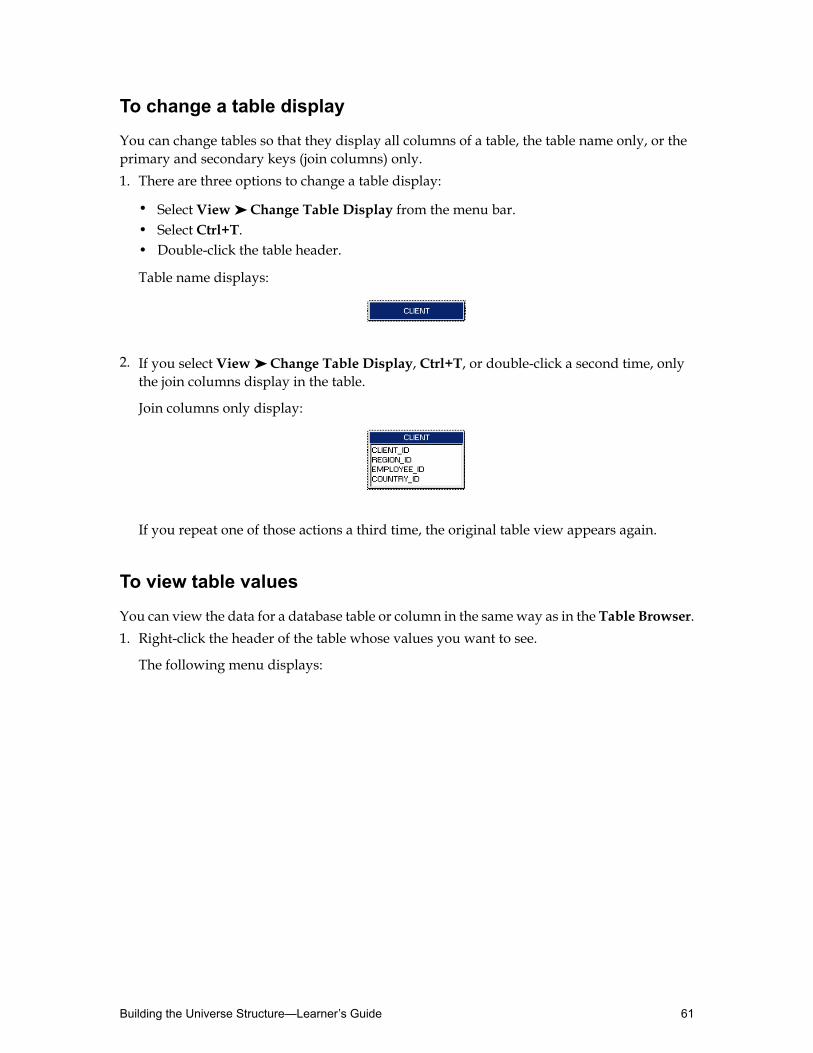
To change a table display
You can change tables so that they display all columns of a table, the table name only, or theprimary and secondary keys (join columns) only.1. There are three options to change a table display:
• Select View ➤ Change Table Display from the menu bar.• Select Ctrl+T.• Double-click the table header.
Table name displays:
2. If you select View ➤ Change Table Display, Ctrl+T, or double-click a second time, onlythe join columns display in the table.
Join columns only display:
If you repeat one of those actions a third time, the original table view appears again.
To view table values
You can view the data for a database table or column in the sameway as in the Table Browser.1. Right-click the header of the table whose values you want to see.
The following menu displays:
61Building the Universe Structure—Learner’s Guide
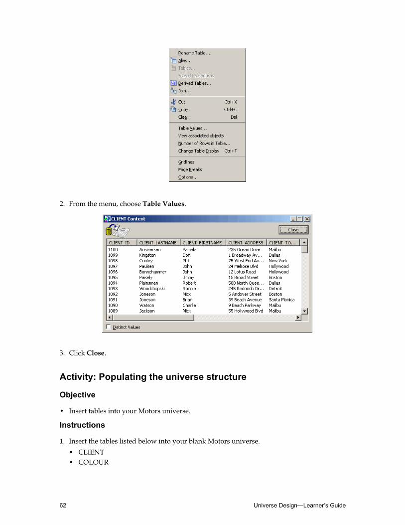
2. From the menu, choose Table Values.
3. Click Close.
Activity: Populating the universe structure
Objective
• Insert tables into your Motors universe.
Instructions
1. Insert the tables listed below into your blank Motors universe.• CLIENT• COLOUR
Universe Design—Learner’s Guide62

• COUNTRY• FINANCE_PERIOD• MAKER• MODEL• REGION• SALE• SALES_PRICE_RANGE• SALE_MODEL• SHOWROOM• STYLE
2. Order the tables so that they are laid out in the same way as the illustration below.
3. Save the changes to your universe.
63Building the Universe Structure—Learner’s Guide
Contact For Any SAP Module Materials : [email protected] ll VISIT: www.sapcertified.com ll
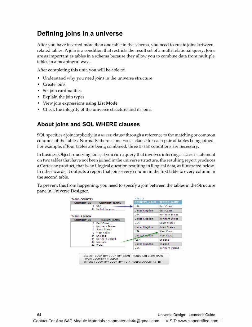
Defining joins in a universeAfter you have inserted more than one table in the schema, you need to create joins betweenrelated tables. A join is a condition that restricts the result set of a multi-relational query. Joinsare as important as tables in a schema because they allow you to combine data from multipletables in a meaningful way.
After completing this unit, you will be able to:
• Understand why you need joins in the universe structure• Create joins• Set join cardinalities• Explain the join types• View join expressions using List Mode• Check the integrity of the universe structure and its joins
About joins and SQL WHERE clauses
SQL specifies a join implicitly in a WHERE clause through a reference to thematching or commoncolumns of the tables. Normally there is one WHERE clause for each pair of tables being joined.For example, if four tables are being combined, three WHERE conditions are necessary.
In BusinessObjects querying tools, if you run a query that involves inferring a SELECT statementon two tables that have not been joined in the universe structure, the resulting report producesa Cartesian product, that is, an illogical question resulting in illogical data, as illustrated below.In other words, it outputs a report that joins every column in the first table to every column inthe second table.
To prevent this from happening, you need to specify a join between the tables in the Structurepane in Universe Designer.
Universe Design—Learner’s Guide64
Contact For Any SAP Module Materials : [email protected] ll VISIT: www.sapcertified.com ll

Creating joins
You have several approaches to creating joins in Universe Designer:• Defining joins manually in the schema.
• Defining join properties directly in the Edit Join dialog box.
• Using the Join SQL Editor to specify the join expression.
Each of these approaches is described in detail below.
Defining joins manually in the schema
You can graphically create individual joins between tables by using the mouse to drag a linefrom a column in one table to a matching column in another table.
Creating the join by defining properties
You can also create a join by directly defining the join properties in the Edit Join dialog box.
To create a join by tracing manually
1. Click on any blank area of the Structure pane to deselect all tables.
2. Position the pointer over a column that you want to be one end of a join.
The pointer appears as a hand symbol.
3. Click and hold down the left mouse button.
The column is highlighted.
4. Drag the mouse to the column in another table that you want to be the other end of the join.
As you drag, the pointer changes into a pencil symbol.
5. Position the pencil symbol over the target column.
The target column is highlighted.
6. Release the mouse button.
The join between the two tables is created. Note that the definition of the join appears in theFormula Bar toolbar.
7. Double-click the new join.
The Edit Join dialog box appears showing the join properties.
65Building the Universe Structure—Learner’s Guide

8. Enter and select properties for the join.
9. ClickOK to close the Edit Join dialog box.
To create a join using the Edit Join dialog box
1. Select Insert ➤ Join from the menu, or click the Insert join button.
The Edit Join dialog box appears.
2. Select a table from the Table1 drop-down list.
The columns for the selected table appear in the list box under the table name.
3. Click the name of the column that you want to be at one end of the new join.
4. Select a table from the Table2 drop-down list box.
The columns for the selected table appear in the list box under the table name.
5. Click the name of the column that you want to be at the other end of the new join.
The join expression is dynamically built in the zones below and can bemodified as necessary.
6. ClickOK.
The new join appears in the schema, linking the two tables and columns that you specifiedin the Edit Join dialog box.
Universe Design—Learner’s Guide66

Note: Another method for inserting a join is to click the first table in the Structure pane,hold down the Ctrl key, click the other table, and then click Insert Join. The two tables areautomatically entered in the Edit Join box and you can edit the join properties as required.
About join properties
You can define the following properties for a join.
DescriptionProperty
Table at the left end of the join. Columns are listed for the tableselected in the drop-down list.Table1
Table at the right side of the join. Columns are listed for the tableselected in the drop-down list.Table2
Operator that defines how the tables are joined.Operator
When selected, determineswhich table contains unmatcheddatain an outer join relationship.Outer Join
When selected, allows you to define the cardinality for the join.Cardinality
Defines the join as a shortcut join.Shortcut Join
A WHERE clause used to restrict the data that is returned whenthe two joined tables are included in a query. This clause can beedited as necessary.
Expression
Join operators
You can select an operator for a join from the drop-down list between the Table1 and Table2selection boxes. The operator allows you to define the restriction that the join uses to matchdata between the joined columns.
You can select the following operators for a join:
DescriptionOperator
equal to=
not equal to!=
67Building the Universe Structure—Learner’s Guide
DescriptionOperator
greater than>
less than<
greater than or equal to>=
less than or equal to<=
between (theta joins)Between
complex relationshipComplex
Editing the join expression
Use the Edit Join dialog box to define and edit join properties. You can also access the JoinSQL editor to edit join syntax directly from this dialog box.
The Edit Join dialog box also has two features available that allow you to edit and verify thejoin syntax:
Edit
The Edit button opens an SQL editor. Use this graphic editor to modify the syntax for tables,columns, operators, and functions used in the join.
Parse
The Parse button starts a parsing function that verifies the SQL syntax of the join expression.If the parse is successful, you receive a result is OK message. If Universe Designer encountersan error, you receive an error message indicating the source of the problem.
Using the Join SQL editor
You can use a graphical editor to directly modify the SQL expression for a join. You access thiseditor from the Edit Join dialog box by clicking the Edit button.
To modify a join using the Join SQL editor
1. Double-click a join in the Structure pane, or click a join and select Edit ➤ Join.
The Edit Join dialog box appears.
Universe Design—Learner’s Guide68

2. Below the Expression text box, click the Edit... button.
The Join SQL Definition dialog box appears. The SQL expression for the join appears inthe text box.
3. Modify the SQL syntax as required.
You can use the following editing features to modify or add SQL syntax:
Then...If you want to...
Expand the table + box in the Tables andColumns selection box and double-click ona new column name.
Change a column at either join end
Double-click an operator in the Operatorsselection box.
Change an operator used by the join
In the Functions selection box, expand afunction family + box and double-click ona new function, or edit the SQL text directly.
Use a function in the join
The column, operator, or function appears in the join definition.
4. ClickOK to validate your changes.
5. Verify that the join expression in the Expression text box has been modified.
6. ClickOK to close the Edit Join dialog box.
69Building the Universe Structure—Learner’s Guide
Contact For Any SAP Module Materials : [email protected] ll VISIT: www.sapcertified.com ll

Detecting joins
Joins can also be created automatically. This procedure can be applied to multiple tables or, ifnone are selected, all tables in the Structure pane.
Note: The automatic detection of joins assumes that all columns with matching names are to bejoined, and other columns are ignored. This may not be appropriate, in which case it is better toinsert the joins manually.
To detect joins automatically
1. Click the table you want to select joins for.
Note: You can select multiple tables by pressing the Shift key, and clicking each table. Youcan also select all tables in a zone by clicking in an empty space, and dragging the cursor todefine a rectangular zone that includes any number of tables.
2. To detect the joins automatically:
• Select Tools ➤ Automated Detection ➤ Detect Joins.• Click theDetect Joins button from the Editing toolbar.
A Candidate Joins dialog box displays listing all the joins detected.
3. Click the join or joins you want to accept in the Candidate Joins dialog box.
Note: You can accept and insert several joins at the same time using Shift-click or Ctrl-click.
4. Click Insert.
The join or joins are inserted in the Structure pane.
5. Click Close.
Setting join cardinalities
Setting cardinality is a critical step in universe development. Cardinality is the term that refersto the relationship between two tables based on a join, specifically howmany rows in one tablewill match those in the other. Whether or not cardinality is defined or how it is defined doesnot directly impact the SQL that is inferred in universe queries. Rather, a universe designerdefines cardinality to benefit from powerful assistance from the Universe Designerresolving-loops tool.
About cardinality
Cardinality is themeans bywhichUniverseDesigner identifies the relationships between tablesin the universe structure. The cardinality can be:• One-to-one (1-1).
• One-to-many (1-N).
Universe Design—Learner’s Guide70
Contact For Any SAP Module Materials : [email protected] ll VISIT: www.sapcertified.com ll

• Many-to-one (N–1).
• Many-to-many (N-N).
For example, a country can have many regions, so the relationship between a Country and aRegion table is 1-N.
Universe Designer uses cardinality to detect and resolve loops.
Note: It is very important that all cardinalities are set correctly for loop and context detection.
You can choose to set cardinality manually or by using an automatic detection tool.
Setting cardinality manually or with the automatic detection tool
Cardinality in universe design is based on a logical algorithm using a physical count. Theautomatic detection tool only works properly if the database is populated with realistic datain a completely normalized structure (for example, no multiple lookup tables or other tricksthat are sometimes applied by database administrators).
Also, it is important to understand that because the detection tool runs three queries on everyjoin, it can take a long time to complete the detection method. The cardinality detection toolworks by running the following queries:• A count of the rows in each of the two tables that are joined (two queries).
• A count of the rows outputwhen applying a querywith the join specified in the WHERE clause(one query).
For these reasons, you are strongly advised to apply cardinality manually for efficiency andaccuracy.
When you set cardinalities manually, you must consider each individual join. This helps youto become aware of potential join path problems in your schema.
You may not find these problems if you only select automatically detected cardinalities; forexample, isolated one-to-one joins at the end of a join path, or excessive primary keys wherenot all columns are required to ensure uniqueness.
To set cardinality manually
It is recommended that you systematically set the join cardinality when you first create a join,using the following manual method.1. Double-click a join, or click a join and select Edit ➤ Properties.
71Building the Universe Structure—Learner’s Guide
Contact For Any SAP Module Materials : [email protected] ll VISIT: www.sapcertified.com ll
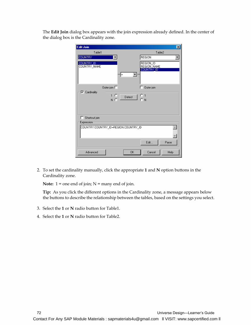
The Edit Join dialog box appears with the join expression already defined. In the center ofthe dialog box is the Cardinality zone.
2. To set the cardinality manually, click the appropriate 1 andN option buttons in theCardinality zone.
Note: 1 = one end of join; N = many end of join.
Tip: As you click the different options in the Cardinality zone, a message appears belowthe buttons to describe the relationship between the tables, based on the settings you select.
3. Select the 1 orN radio button for Table1.
4. Select the 1 orN radio button for Table2.
Universe Design—Learner’s Guide72
Contact For Any SAP Module Materials : [email protected] ll VISIT: www.sapcertified.com ll

5. ClickOK to accept your changes and close the Edit Join dialog box.
Displaying cardinalities
You can display cardinalities in the Structure pane using the following symbols:
DescriptionExampleCardinality symbol
Arrow indicates the“one”direction of the join. If
Arrow cardinality is 1:1 then anarrow head is shown at eachjoin end.
Crow’s foot indicates the“many” end of the join. IfArity cardinality is 1:1, then astraight line is shown.
73Building the Universe Structure—Learner’s Guide
Contact For Any SAP Module Materials : [email protected] ll VISIT: www.sapcertified.com ll
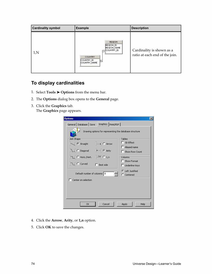
DescriptionExampleCardinality symbol
Cardinality is shown as aratio at each end of the join.1,N
To display cardinalities
1. Select Tools ➤ Options from the menu bar.
2. TheOptions dialog box opens to theGeneral page.
3. Click theGraphics tab.TheGraphics page appears.
4. Click the Arrow, Arity, or 1,n option.
5. ClickOK to save the changes.
Universe Design—Learner’s Guide74

Detecting cardinality automatically
You can set Universe Designer to detect cardinality automatically as you insert joins, howeverit is recommended that you use the manual method described previously, to ensure accurateresults.
You can detect cardinality for a single join by selecting that join and clicking theDetectCardinalities icon in the Editing toolbar. This is due to the fact that, if the database is large,running the cardinality detection queries for every join can take considerable time.
How is cardinality detected?
To detect the cardinality of a join between two tables, the following three queries are run:SELECT count (*)FROM table1, table2WHERE table1.column = table2.columnSELECT count (*)FROM table1SELECT count (*)FROM table2.
The results of the three queries are then compared in an attempt to determine which query isthe end of the join with one entity and which is the end with many (if there is one).
To detect cardinality on a single join
Cardinality can be detected on a single join using one of two methods.1. Using the Edit Join dialog box:
a. Double-click the join in the Structure pane to open the Edit Join dialog box.b. In the Cardinality zone of the Edit Join dialog box, click theDetect button.c. Check the cardinality statement tomake sure that the one-to-many relationship proposed
makes logical sense.d. ClickOK to accept the proposed cardinality and close the Edit Join dialog box.
In the Structure pane, UniverseDesigner applies the cardinality symbol to the appropriateend of the join, based on the cardinality proposed by the detection tool.
2. Using theDetect Cardinality button:a. Select the join.b. Click theDetect Cardinalities button.
The automatic tool detects the cardinality of the join and applies the arity symbol to theappropriate end of the join.
c. Check the arity symbols displayed between the tables tomake sure that the one-to-manyrelationship proposed makes logical sense.
d. Edit the cardinality proposed in the Edit Join dialog box if necessary.
75Building the Universe Structure—Learner’s Guide

Detect cardinality for all joins
You can use the Universe Designer featureDetect Cardinalities to automatically detect alljoins in the schema.
When using automatic cardinality detection, cardinalities are implemented automatically ondetection.
You should use automatic cardinality detection appropriately. It can be very useful to quicklyget all the cardinalities detected in the schema, however, there are a number of structuralproblems inherent inmany relational databaseswhich can lead to incorrect cardinality detection.
To detect cardinality for all joins
You can also detect cardinality all at the same time, although this is not a recommendedprocedure to ensure accurate results.1. Click the Structure pane background to ensure no join is selected.
2. Click the Check Cardinality button on the toolbar.
Note: Cardinality is detected by automatically running three subsequent queries at thetarget database per join. You are therefore advised to avoid automatic detection ofcardinalities on large databases. Use the manual method whenever cardinality is known.
A message appears.
Universe Designer requests confirmation because executing the detection tool takes a longtime if it is being applied to a large database.
3. If you are sure you want to use the automatic detection tool, clickOK to detect thecardinalities.
Universe Design—Learner’s Guide76

The system inserts the cardinality symbols on the many ends of the joins.
4. Universe Designer offers yet another method for detecting cardinalities automatically:1. Select Tools ➤ Options from the menu bar.
2. Click theDatabase tab.
3. Select theDetect cardinalities in joins check box.
4. ClickOK.
Best practices for setting join cardinality
As mentioned previously, there are three reasons why using the automatic detection tool toset join cardinalities is not recommended:• Cardinality is based on logic. It is logical that every country has more than one region; it is
not logical that a regionmay havemore than one country. The automatic detection tool usesphysical cardinality, and runs a physical count on the values in both columns being joined.Youmay get incorrect results if the physical count does not return the same result as a logicalanalysis of the data.
• The algorithmused by the automatic detection tool assumes that you have sufficient quantityof data in both tables to be representative in ratio to the database in a live environment. Ifyou are designing against a test database, for example, with only a representative samplingof data, you could receive an incorrect answer because the tool runs a physical count.
• The automatic detection tool runs three subsequent queries against the target database perjoin. You are, therefore, advised to avoid automatic detection of cardinalities on largedatabases.
77Building the Universe Structure—Learner’s Guide
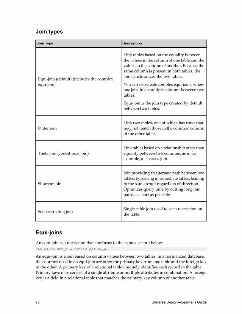
Join types
DescriptionJoin Type
Link tables based on the equality betweenthe values in the column of one table and the
Equi-join (default) (includes the complexequi-join)
values in the column of another. Because thesame column is present in both tables, thejoin synchronizes the two tables.
You can also create complex equi-joins,whereone join linksmultiple columns between twotables.
Equi-join is the join type created by defaultbetween two tables.
Link two tables, one of which has rows thatmay not match those in the common columnof the other table.
Outer join
Link tables based on a relationship other thanequality between two columns, as in forexample, a BETWEEN join.
Theta join (conditional join)
Join providing an alternate path between twotables, bypassing intermediate tables, leading
Shortcut join to the same result regardless of direction.Optimizes query time by cutting long joinpaths as short as possible.
Single-table join used to set a restriction onthe table.Self-restricting join
Equi-joins
An equi-join is a restriction that conforms to the syntax set out below:Table1.column_a = Table2.column_a
An equi-join is a join based on column values between two tables. In a normalized database,the columns used in an equi-join are often the primary key from one table and the foreign keyin the other. A primary key of a relational table uniquely identifies each record in the table.Primary keys may consist of a single attribute or multiple attributes in combination. A foreignkey is a field in a relational table that matches the primary key column of another table.
Universe Design—Learner’s Guide78
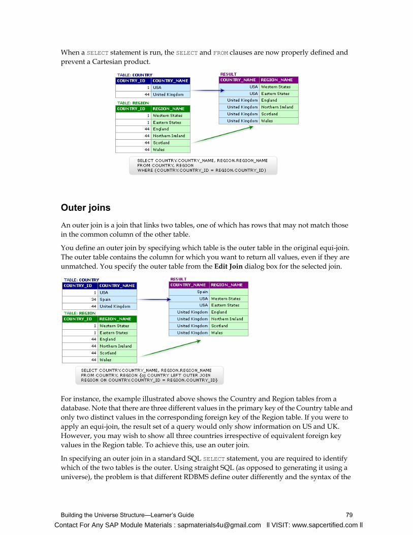
When a SELECT statement is run, the SELECT and FROM clauses are now properly defined andprevent a Cartesian product.
Outer joins
An outer join is a join that links two tables, one of which has rows that may not match thosein the common column of the other table.
You define an outer join by specifying which table is the outer table in the original equi-join.The outer table contains the column for which you want to return all values, even if they areunmatched. You specify the outer table from the Edit Join dialog box for the selected join.
For instance, the example illustrated above shows the Country and Region tables from adatabase. Note that there are three different values in the primary key of the Country table andonly two distinct values in the corresponding foreign key of the Region table. If you were toapply an equi-join, the result set of a query would only show information on US and UK.However, you may wish to show all three countries irrespective of equivalent foreign keyvalues in the Region table. To achieve this, use an outer join.
In specifying an outer join in a standard SQL SELECT statement, you are required to identifywhich of the two tables is the outer. Using straight SQL (as opposed to generating it using auniverse), the problem is that different RDBMS define outer differently and the syntax of the
79Building the Universe Structure—Learner’s Guide
Contact For Any SAP Module Materials : [email protected] ll VISIT: www.sapcertified.com ll

statement also differs. For example, depending on the underlying RDBMS, the outer join maybe on the left or right.
In a universe, the outer join is always placed on the table that contains all the data. That is, onCountry in the example above. To do this, place a check against the table that contains all thedata in the Edit Join dialog box.
Tip: A goodway to find out where to place your outer join is by reading the description that showsup in the Cardinality zone. If you select the outer join check box for Country the description reads:
Each Country has ZERO or more Regions, AND each Region has one and only one Country.
When you check the outer join box for the Country table, you retrieve all countries whetherthey have a region or not.
Once this is done, the correct outer join is inferred when used in the generated query, and thesyntax is correctly inferred for the appropriate RDBMS (assuming you have the correct SQLinference driver).
An outer join is shown by a small circle on the join line in the universe structure at the end thatpoints to the table that may have missing values.
Best Practice with Outer Joins
It is recommended that outer joins be placed at the end of the flow of data, otherwise ambiguousouter join errorsmay occur. Potentially, this could cause the SQL to try tomatch on the equalityof a NULL value, which it cannot do.
Universe Design—Learner’s Guide80
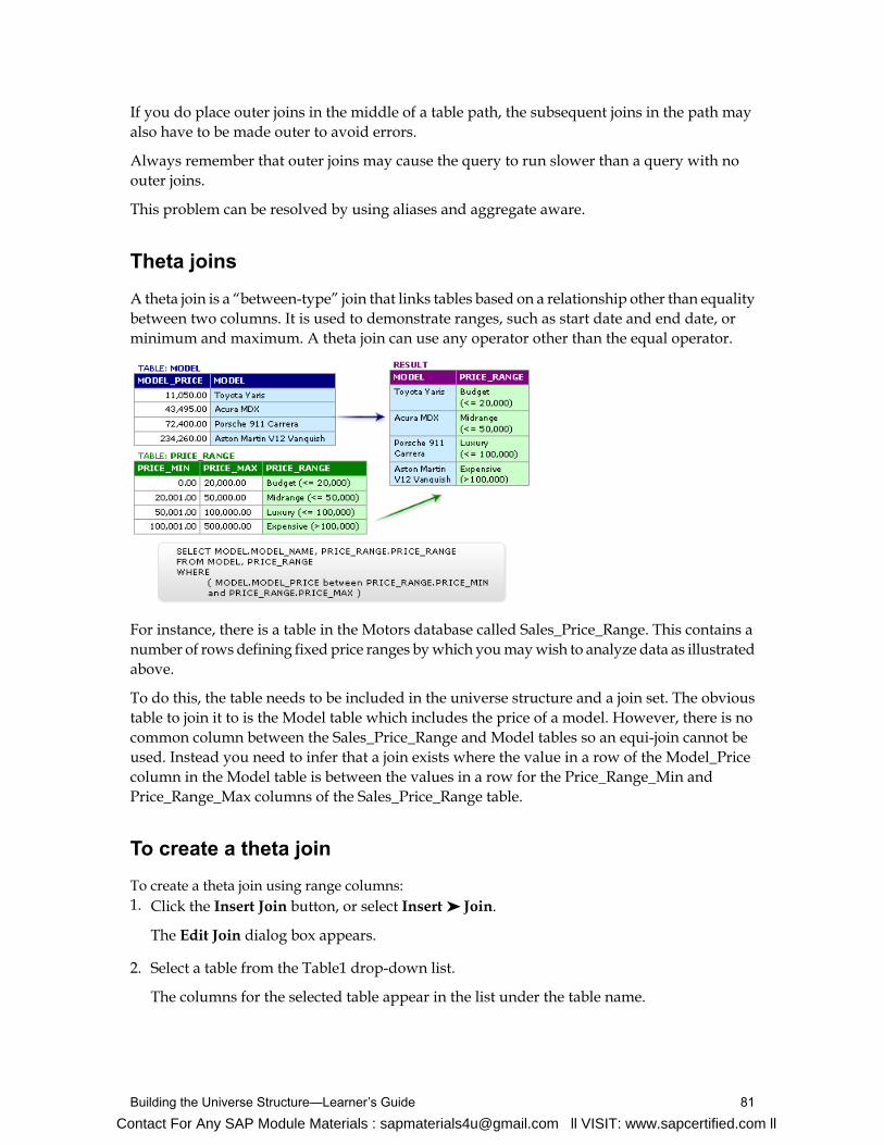
If you do place outer joins in the middle of a table path, the subsequent joins in the path mayalso have to be made outer to avoid errors.
Always remember that outer joins may cause the query to run slower than a query with noouter joins.
This problem can be resolved by using aliases and aggregate aware.
Theta joins
A theta join is a “between-type” join that links tables based on a relationship other than equalitybetween two columns. It is used to demonstrate ranges, such as start date and end date, orminimum and maximum. A theta join can use any operator other than the equal operator.
For instance, there is a table in the Motors database called Sales_Price_Range. This contains anumber of rows defining fixed price ranges bywhich youmaywish to analyze data as illustratedabove.
To do this, the table needs to be included in the universe structure and a join set. The obvioustable to join it to is the Model table which includes the price of a model. However, there is nocommon column between the Sales_Price_Range and Model tables so an equi-join cannot beused. Instead you need to infer that a join exists where the value in a row of the Model_Pricecolumn in the Model table is between the values in a row for the Price_Range_Min andPrice_Range_Max columns of the Sales_Price_Range table.
To create a theta joinTo create a theta join using range columns:1. Click the Insert Join button, or select Insert ➤ Join.
The Edit Join dialog box appears.
2. Select a table from the Table1 drop-down list.
The columns for the selected table appear in the list under the table name.
81Building the Universe Structure—Learner’s Guide
Contact For Any SAP Module Materials : [email protected] ll VISIT: www.sapcertified.com ll

3. Click the column you want to join.
4. Select the a table from the Table2 drop-down list.
The columns for the selected table appear in the list under the table name.
5. Press and hold down the Ctrl key and click two columns from the Table2 column list box.
Note: The operand changes toBetween automatically, and indicates that the join expressionis dynamically built as a BETWEEN syntax.
6. Click the Parse button to test for the validity of the join.If you receive an error message, check to see that you have correctly selected the columns.
7. Set the correct cardinality.
8. ClickOK.
The theta join now appears between the two selected tables.
Shortcut joins
A common use of shortcut joins is to link a shared lookup table to another table further alonga join path. The join path is comprised of several different tables in the same context.
A shortcut join is a join that provides an alternate path between two tables. It improves theperformance of a query by not taking into account intermediate tables, and shortening a normallylonger join path.
Universe Design—Learner’s Guide82

In such a case, the shortcut join is only effective when the value being looked up has beendenormalized to lower levels in a hierarchy of tables so the same value exists at all the levelsbeing joined.
Self-restricting joins
A self-restricting join is not really a join at all, but a self-restriction on a single table, usually atransaction table. You can use a self-restricting join to restrict the results returned by a tableusing a fixed value.
The table in the example above contains rows of data for cars both sold and rented. The saletype column is used as a flag to indicate the type of transaction. Without the self-restrictingjoin, the results set of the query would produce rows where the sale type column is equal toeither car sales ('S') or car rental ('R'). With the self-restricting join expression set to sale typeequal to ‘S’, any object based on the table or joins passing through that table would producequery results covering only car sales.
To create a self-restricting join
1. Use one of the following methods to insert a join:
• Click on the Insert Join button.• Select Insert ➤ Join.
The Edit Join dialog box appears.
2. Select the table from the Table1 drop-down list.
Select the table that you want to set the self-restricting join against from the Table1 drop-down list box.
The columns for the selected table appear in the list under the table name.
3. Click the column that you want to use to define the restriction from the column drop-downlist box.
4. From the Table2 drop-down list, select the same table that you selected from the Table1drop-down list box.
83Building the Universe Structure—Learner’s Guide
Contact For Any SAP Module Materials : [email protected] ll VISIT: www.sapcertified.com ll

5. Click the same column that you selected in the Table1 column list box.The expression for the join appears in the Expression text box.
6. Replace the operand value in the join expression with the restriction value that you wantto set on the join column.
For example, if you want to restrict the returned values from the sale type column to carsales values only, you replace SALE.SALE_TYPE after the = sign with 'S' as shown below.
Tip: This can also be done directly in the Expression field.
Note: It is recommend that you set the cardinality of a self-restricting join to 1:1. Otherwise,when running detect contexts, you get an error that not all cardinalities have been detected.
7. ClickOK
The self-restricting join now appears as an unconnected join line.
You can view the join expression underlying a join line or all the join expressions for a tableusing List Mode as well as the Edit Join dialog box.
Universe Design—Learner’s Guide84

List Mode
You can use List Mode to list the tables, joins, and contexts used in the active universe. In ListMode, Universe Designer adds three panes above the display of the Structure pane; tables,joins, and contexts. You can view the join expression underlying a join line or all join expressionsfor a table using List Mode as well as the Edit Joins dialog box.
To use List Mode
1. Click the View List Mode button.
After ListMode opens, you can view tables and join information and expressions in variousways. For example:
2. Click a join in the graphical Structure pane.
The expression for the join is highlighted in the Joins pane in List Mode.
3. Click a table in the Tables pane of ListMode, and click the arrow pointing to the Joins pane.
Only the joins for the selected table are shown in the Joins pane.
4. Clear the highlighted arrow to view all the joins and tables again.
5. Click the View List Mode button to return to normal view.
85Building the Universe Structure—Learner’s Guide

Note: Ensure you clear any arrows in List Mode before returning to normal view. The restrictedview of tables could interfere with operations that you perform in normal view, such as detectingcontexts.
Checking integrity
Use the Check Integrity option to detect any errors in the structure and joins of a universe.
Be careful of checking cardinality automatically for all the reasons mentioned previously. Asa general rule, never select the Check Cardinalities check box when you are checking theintegrity of your universe.
To check the integrity of a universe
1. Click the Check Integrity button.
The Integrity Check dialog box displays:
2. Select check boxes for components to be verified.
3. Clear check boxes for components not to be verified.
4. ClickOK.Universe Designer checks the universe and displays the Integrity Check Results dialogbox.If there are no errors, clickOK. Otherwise, you need to return to your Structure pane andcorrect any errors as indicated in the Integrity Check Results dialog box.
Note: Some divergences in integrity results are acceptable.
Universe Design—Learner’s Guide86

Activity: Defining joins in a universe
Objective
• Insert joins between tables in your Motors universe and set cardinalities.
Instructions
1. Insert the following equi-join using the drag-and-drop technique:• COUNTRY.COUNTRY_ID to REGION.COUNTRY_ID
2. Set the cardinality for the join manually in the Edit Join dialog box.
3. Insert the following equi-join using the Edit Join dialog box and set the cardinality.• REGION.REGION_ID to CLIENT.REGION_ID
4. Check integrity for:• Universe structure and joins
5. Notice the divergences found in the integrity check of your Motors universe, which is theresult of having unjoined tables.
87Building the Universe Structure—Learner’s Guide
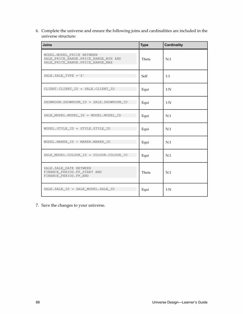
6. Complete the universe and ensure the following joins and cardinalities are included in theuniverse structure:
CardinalityTypeJoins
N:1ThetaMODEL.MODEL_PRICE BETWEEN SALE_PRICE_RANGE.PRICE_RANGE_MIN ANDSALE_PRICE_RANGE.PRICE_RANGE_MAX
1:1SelfSALE.SALE_TYPE ='S'
1:NEquiCLIENT.CLIENT_ID = SALE.CLIENT_ID
1:NEquiSHOWROOM.SHOWROOM_ID = SALE.SHOWROOM_ID
N:1EquiSALE_MODEL.MODEL_ID = MODEL.MODEL_ID
N:1EquiMODEL.STYLE_ID = STYLE.STYLE_ID
N:1EquiMODEL.MAKER_ID = MAKER.MAKER_ID
N:1EquiSALE_MODEL.COLOUR_ID = COLOUR.COLOUR_ID
N:1ThetaSALE.SALE_DATE BETWEEN FINANCE_PERIOD.FP_START ANDFINANCE_PERIOD.FP_END
1:NEquiSALE.SALE_ID = SALE_MODEL.SALE_ID
7. Save the changes to your universe.
Universe Design—Learner’s Guide88

Quiz: Building the universe structure1. A schema contains two elements. What are they?
2. What are three reasonswhyusing the automatic detection routine for setting join cardinalitiesis not recommended?
3. What type of join is created by default between two tables?
89Building the Universe Structure—Learner’s Guide
Contact For Any SAP Module Materials : [email protected] ll VISIT: www.sapcertified.com ll

Lesson summaryAfter completing this lesson, you are now able to:
• Populate the universe structure• Define joins in a universe
Universe Design—Learner’s Guide90
Contact For Any SAP Module Materials : [email protected] ll VISIT: www.sapcertified.com ll
Lesson 4Creating Dimension Objects
Lesson introductionThis lesson describes how you can create classes and objects that are used by end users to runqueries and create reports.
After completing this lesson, you will be able to:
• Describe classes and objects• Create classes and objects
91Creating Dimension Objects—Learner’s Guide
Contact For Any SAP Module Materials : [email protected] ll VISIT: www.sapcertified.com ll

Describing classes and objectsBecause universes are made up of objects and classes, it is important to understand exactlyhow each of these elements is used.
After completing this unit, you will be able to:
• Describe universe objects• Describe universe classes
Classes
Within a universe, objects are grouped into classes. This is done to provide a structure for theuniverse and makes it easier for users to locate particular objects. The strategy most oftenemployed is to group related dimension and detail objects into one class and place measureobjects into a unique and single-measures class.
This strategy can be extended by introducing subclasses to break down the objects into furthersubsets.
Each object in a universe must be contained within a class. You can create new classes and editthe properties of existing classes. Classes are represented as folders on a tree hierarchy in theUniverse pane.
In Universe Designer, you can qualify an object as being one of three types:
DescriptionExamplesObject qualification
Focus of analysis in a query.A dimension maps to one or
Dimension more columns or functionsin the database that are keyto a query.
Provides descriptive dataabout a dimension. A detail
Detail
is always attached to adimension. It maps to one ormore columns or functionsin the database that providedetailed information relatedto a dimension.
Universe Design—Learner’s Guide92
Contact For Any SAP Module Materials : [email protected] ll VISIT: www.sapcertified.com ll

DescriptionExamplesObject qualification
Contains aggregate functionsthat map to statistics in the
Measure database. These are themetrics by which you wantto compare dimensions.
Dimension objects, where possible, tend to be organized hierarchically within a class. This isimportant if you intend to make use of default hierarchies for drilling. Detail objects areorganized below their associated dimension objects.
Note: Detail objects cannot be included in a drill path.
Measure objects may be grouped in a separate class. This makes them easier for the user tofind and also emphasizes the fact that they can be used with any dimension or detail object.
Note: Only dimension objects can bemerged to synchronize queries frommultiple data sourcesin end-user querying tools.
Objects
In Business Objects products, an object is a named component in a universe that represents acolumn or function in a database.
In Universe Designer, objects appear as icons in the Universe pane. Each object represents ameaningful entity, fact, or calculation used in an end user’s business environment. The objectsthat you create in the Universe pane in Universe Designer are the objects that end users seeand use in the Business Objects end-user querying tools.
For example, in theWeb Intelligence Rich ClientQuery Panel, users drag objects from theDatatab into theResult Objects pane to run queries and create reports that display the data returnedby the query.
Each object maps to a column or function in the target database, and when an object is selectedin theQuery Panel, the object infers a SELECT statement. When multiple objects are combined,a SELECT statement is run on the database which includes the SQL inferred by each object anda default WHERE clause.
93Creating Dimension Objects—Learner’s Guide

As a universe designer, you use Universe Designer to create the objects that end users selectto build and run their queries.
You can also create objects for use only in Universe Designer, so that they are hidden in theBusiness Objects end-user querying tools.
Universe Design—Learner’s Guide94

Creating classes and objectsAfter defining classes and objects, the next step is to understand how to employ these elements.
After completing this unit, you will be able to:
• Create a class
• Create objects
• Create classes and objects automatically
• Create classes and objects by copy and paste from another universe
• Edit object parameters
• Check integrity
• Test the objects in Web Intelligence Rich Client
Creating classes
A class is a logical grouping of objects within a universe. It represents a category of objects.The name of a class should indicate the category of the objects that it contains. A class can bedivided hierarchically into subclasses.
There are two ways to create a class in the Universe pane:• Manually defining a class.• Automatically by dragging a table from the Structure pane into the Universe pane.
To create a class
In Universe Designer, classes are created in the Universe pane. If the Universe pane is notactivated, it can be opened via View ➤ Universe Window.1. Open your universe file in Universe Designer, and in the Universe pane, click an existing
class, below which you want the new class to appear.
Note: If this is the first class you are creating, ignore this step.
Note: If you create a class when an object within a class is highlighted, a subclass withinthat class is created instead.
2. With the universe file open in Universe Designer, insert a new class. There are three waysyou can insert a class:• Click the Insert Class button from the Editing toolbar.• Select Insert ➤ Class from the menu.• Right-click in the Universe pane and choose Class from the right-click menu.
3. The Edit Properties dialog box displays.
4. In the Class Name field, enter a name.
95Creating Dimension Objects—Learner’s Guide

5. In the Description field, enter a description of the class content. Use business language thatis meaningful to the users in your description for when they review it. Avoid technicaldatabase language.
6. ClickOK.
To manually create an object
1. Open your universe file in Universe Designer, and in the Universe pane, click the class inwhich you want the new object to be placed.
2. With the universe file open in Universe Designer, insert a new object. There are three waysyou can insert an object:
• Click the Insert Object button from the Editing toolbar.• Select Insert ➤ Object from the menu bar.• Right-click the class and chooseObject from the right-click menu.
The Edit Properties dialog box for the object appears.
Universe Design—Learner’s Guide96

3. In the Name field, provide a meaningful object name.
4. In theDefinition tab.
Ensure that object names are always expressed in the end-user business vocabulary. Thisname may be different from the actual column names that the object is associated with inthe database schema.
5. Type a SELECT statement in the Select field, or click the >> button to use the SQL editor.
6. Click the Properties tab and select object properties.
7. ClickOK.
Automatically creating classes and objects from a table
You can also create classes and objects simply by dragging the entire table from the Structurepane into the Universe pane in Universe Designer. This is particularly useful if you are surethat you want all the columns in the table to correspond to objects in the universe.
Note: The class is automatically populated with a dimension object for every column in thetable. It is not advisable to do this because you are creating a universe based on the databasestructure, not on the requirements of the users.
You can create an object automatically by selecting a column in a table in the Structure paneand dragging it to the Universe pane. An object is created under the nearest class to the pointwhere you drop the column. The default name for the object is the column name.
You should edit the new object properties to ensure that it is appropriately named, and isrelevant to end-user needs. Whenever you create an object automatically, edit the propertiesof the object to:• Change the name where appropriate.
• Enter a description.
• Change the object qualification from the default where necessary.
• Alter or remove the associated list of values settings where appropriate.
• Change other settings as required.
To automatically create an object from a column
1. Click a table column in the Structure pane.
2. Drag the column across to the Universe pane and drop the table at the desired position inthe class hierarchy. The column must be dropped under an existing class.
A new object appears in the hierarchy.
97Creating Dimension Objects—Learner’s Guide

Defining a new object as a detail object
TheProperties tab in theEdit Propertiesdialog box allows you to define the object qualification.An object can be qualified as a dimension, detail, or measure object.
A detail object provides descriptive data about a dimension, and is always attached to adimension. It maps to one or more columns or functions in the database that provide detailedinformation related to a dimension.
To define an object as a detail object
1. Double-click an object.The Edit Properties dialog box for the object appears.
2. Click the Properties tab.
The Properties tab of the Edit Properties dialog box appears.
3. In the Qualification zone, select theDetail button.
The Associated Dimension field appears in the Qualification zone.
4. Click theAssociated Dimension field, and from the drop-down list of available dimensionobjects, select the one with which this detail object is to be associated.
5. ClickOK to confirm the change.
Universe Design—Learner’s Guide98

Working with classes and subclasses
A subclass is a class within a class. You can use subclasses to help organize groups of objectsthat are related. A subclass can itself contain other subclasses or objects.
Note: It is recommended that you do not create too many levels of subclasses (more than three).Too many levels make it difficult for users to find the objects they need.
To create a subclass
1. Right-click the class in which you want to create a subclass.The drop-down menu appears.
2. Choose Subclass.
The Edit Properties dialog box displays.
3. In the Class Name field enter the name of the subclass.
4. ClickOK.
The Universe pane should look similar to:
To delete a class or a subclass
1. There are two ways to delete a class, or subclass:
• Click the class, or subclass that requires deletion. Press theDelete key.• Right-click the selected class, or subclass. Select the Clear option from the drop-down
menu.
Editing the object properties
The following example shows the properties of the dimension object, called Client Name.
99Creating Dimension Objects—Learner’s Guide

As the object is currently defined, there is no SELECT statement defined to reference the Clienttable. You need to edit the definition of the SELECT statement so the Client Name object returnsthe complete client name using the appropriate columns from the Client table.
Note: The example above shows a concatenation of two columns. Depending on the RDBMSused the syntax can vary. Consult the documentation provided by your database vendor tosee what types of concatenation functions are supported.
Universe Design—Learner’s Guide100

To edit the object definition
1. Double-click the object that you want to edit.
2. In theDefinition tab, type in the Name field if you want to edit the object name.
3. Click the Type arrow, and from the drop-down list, select the appropriate data type for thedatabase column, or columns that the object references.
4. In the Description field type help text for the end user.This text appears in Business Objects end-user querying tools when a user selects the objectto build a query. The text describes the data returned when the user adds this object to aquery.
5. In the Select field enter the SQL statement that gets inferred when a user builds a queryusing this object.
This can be done in one of two ways:• Type the SELECT syntax in the Select field to define the columns that get referenced.• Click the >> button to open the Edit Select Statement dialog box as displayed below.
The Edit Select Statement dialog box appears.
It is normally best to use the latter method because it enables you to specify most of theSELECT syntax from pick lists in the lower half of the screen by double-clicking the itemrequired. This minimizes typing and averts syntax errors due to typing mistakes.
6. Create the SELECT statement so the object references the appropriate table columns.
Note: You can use the fields below the text box to select the columns, operators or functionsyou need to use to enter the required SQL syntax.
101Creating Dimension Objects—Learner’s Guide

7. Click the Parse button to validate the statement syntax.
8. ClickOK to close the Edit Select Statement dialog box.
The Edit Select Statement dialog box closes and theDefinition tab of the Edit Propertiesdialog box displays the SQL statement in the Select field.
Edit Properties: Properties
The Properties tab in the Edit Properties dialog box allows users to:1. Select one of the object types in the Qualification zone.
Note: By default, the object type selected is either a dimension or measure dependent onthe data type chosen on theDefinition tab:
• Dimension = Character, Date or Number.• Measure = Selected by default when there is an aggregate function in the SELECT clause.
Note: TheDetail qualification check box is grayed out if no dimension objects exist towhich to attach a detail object.
2. Select the appropriate options in the Associate a List of Values zone.
What is a list of values?
When you create an object, Universe Designer automatically associates a list of values (LOV)with the object. The LOV is not created until a user or the universe designer chooses to displaya list of values for the object in theQuery Panel. A SELECT Distinct query is then run againstthe column or columns inferred by the object.
The returned data is stored in a file with an .lov extension in the universe subfolder createdunder the same folder that stores the universe file. The .lov file is then used as the source forvalues for the list. This allows the SELECT Distinct query to be run only once for an object.
When do you use a list of values?
A list of values should only be used with an object if it provides something useful for the user.LOVs are very useful where there is a limited set of distinct values for the database columnsunderlying the object.
Note: If the object is likely to refer to a large number of distinct rows in the database, it isadvisable not to associate an LOV or change its configuration to avoid performance issues.
Setting LOV options
In the Associate a List of Values zone, theDisplay button allows you to view all the values inthe database returned by this object.
To restrict the object so that some of the values are not returned when an end user uses thisobject in a query, you can click the Edit button to create a filter (or condition) in theQueryPanel that appears.
Universe Design—Learner’s Guide102

Edit Properties: Advanced
The Advanced tab allows you to set the security access level of the object and how it can beused in a query or in a report. You can select a security level which restricts use of the objectto users with the appropriate security level.
In the Security Access Level zone you can assign the following security access levels:• Public
• Controlled
• Restricted
• Confidential
• Private
If you assign Public, then all users can see and use the object. If you assign Restricted, thenonly users with the user profile of restricted or higher can see and use the object.
In the Can be used in zone, select one of the following options to define how this object can beused in a query:• The Result check box - use this object to return results in a query.• The Condition check box - use this object to apply a condition or query filter in a query.• The Sort check box - specify the object in the ORDER BY clause of a SELECT statement.
Note: This option can increase the processing speed of a query. However, in certain editedLOV situations, it is not useful to sort at query level because block-level sorting overridesany row order of data that is stored in the microcube.
103Creating Dimension Objects—Learner’s Guide

Edit Properties: Keys
TheKeys tab allows you to define index awareness for an object. Index awareness is the abilityto take advantage of the indexes on key columns in the database to speed data retrieval.
The objects that you create in Universe Designer are based on database columns that aremeaningful to an end user. For example, a Customer object retrieves the field that contains thecustomer name. In this situation, the customer table typically has a primary key that is notmeaningful to the end user, but which is very important for database performance. When youset up index awareness in Universe Designer, you tell Universe Designer which databasecolumns are primary and foreign keys. This can have a dramatic effect on query performance.
In the example below, primary and foreign keys have been defined on the Client Countryobject. The complete WHERE clause for the primary key is:
COUNTRY.COUNTRY_ID = CLIENT.COUNTRY_ID
If you then use Country and the Client Name object in a query, the query does not need toreference the Country table in the database; the Country data is taken from the Client tabledirectly.
Edit Properties: Source Information
For universes generated from Data Integrator, technical descriptions and formulas used tocalculate target tables from source tables are displayed in this tab.
Universe Design—Learner’s Guide104

You can specify the following types of information in the Source Information tab:
• Technical information: Technical descriptions that are available in universes generated fromData Integrator.
• Mapping information: The mapping applied within Data Integrator between the sourcetables and the target tables. The goal is not to provide the expression of the mapping, butto display it as a descriptive comment to inform the user of the source columns used in theobject definition.
• Data Lineage information: List of source columns involved in a target column. Thisinformation facilitates the impact analysis through Data Integrator and Web Intelligencereports.
It is possible to copy objects fromone universe to another. This is useful if youwant to createobjects that are similar to those already existing in another universe. You can copy thoseobjects or classes of objects and edit them as required.
Note: When you copy an object from one universe into another, be sure to validate theobject definition against the new universe structure and data source connection.
Copying and pasting objects
It is possible to copy objects from one universe to another. This is useful if you want to createobjects that are similar to those already existing in another universe. You can copy those objectsor classes of objects and edit them as required.
Note: When you copy an object from one universe into another, be sure to validate the objectdefinition against the new universe structure and data source connection.
105Creating Dimension Objects—Learner’s Guide
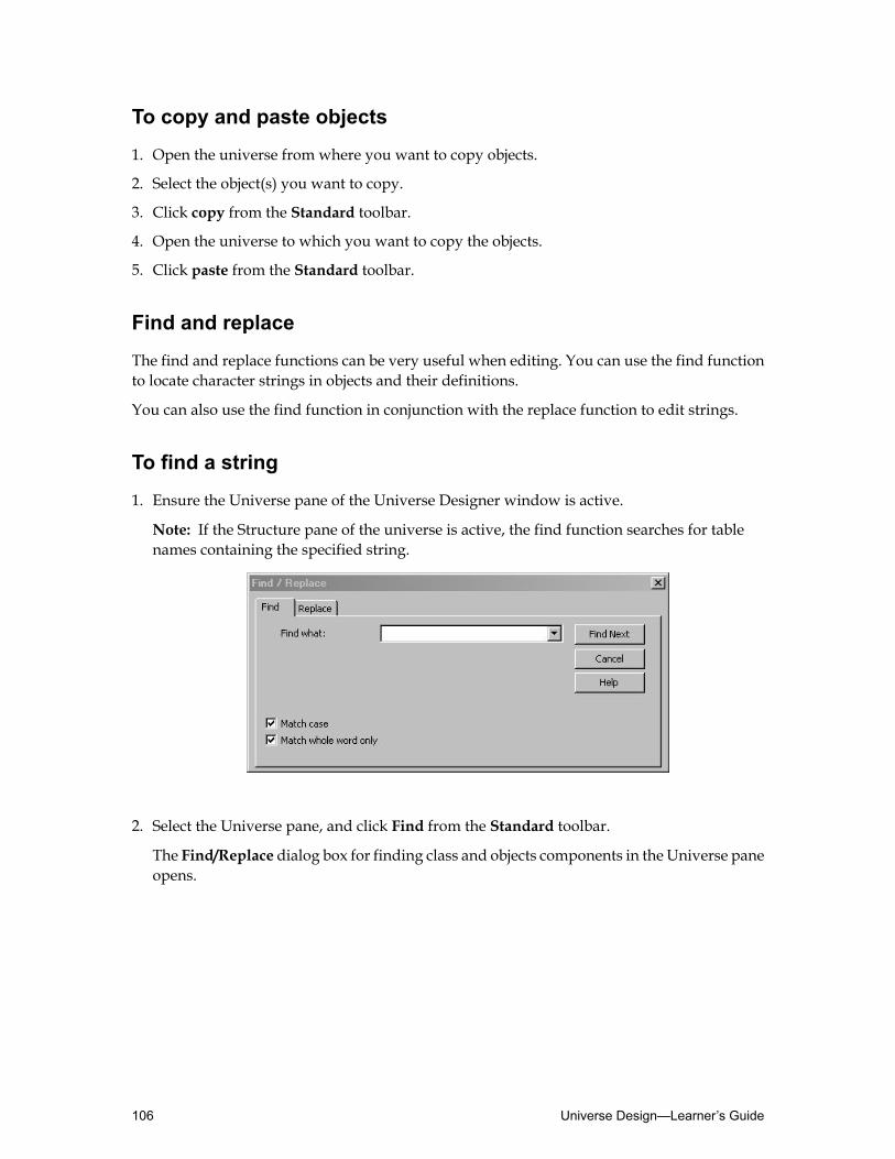
To copy and paste objects
1. Open the universe from where you want to copy objects.
2. Select the object(s) you want to copy.
3. Click copy from the Standard toolbar.
4. Open the universe to which you want to copy the objects.
5. Click paste from the Standard toolbar.
Find and replace
The find and replace functions can be very useful when editing. You can use the find functionto locate character strings in objects and their definitions.
You can also use the find function in conjunction with the replace function to edit strings.
To find a string
1. Ensure the Universe pane of the Universe Designer window is active.
Note: If the Structure pane of the universe is active, the find function searches for tablenames containing the specified string.
2. Select the Universe pane, and click Find from the Standard toolbar.
The Find/Replace dialog box for finding class and objects components in the Universe paneopens.
Universe Design—Learner’s Guide106

3. Enter the character string for which to search.
4. Select the check box options as required.
5. Click Find Next. The appropriate object or part of the object definition is displayed and thestring is highlighted.
6. To move to the next instance of the string, click Find Next or click the Find Next icon.
To replace as you find
1. Ensure the Universe pane of the Universe Designer window is active.
Note: If the Structure pane of the universe is active, Find/Replace searches for table namescontaining the specified string.
2. Select the Universe pane, and click Find from the Standard toolbar.
The Find/Replace dialog box for finding class and objects components in the Universe paneopens. Select the Replace tab.
107Creating Dimension Objects—Learner’s Guide

3. Enter the string to search for in the Find what field and the string with which it is to besubstituted in the Replace field.
4. Select the check boxes as required.
5. Click Find Next.
6. Click Replace and then move to the next instance of the string by either clicking Find Nextor the Standard toolbar option.
Checking object integrity
Always check the integrity of your universe after defining classes and objects.
Use the Check Integrity option to detect any errors in the SQL syntaxes used in the createdobjects.
Note: Ensure that the Check Cardinalities box is cleared. With a large database, this savestime running the integrity check.
To check object integrity
1. Click the Check Integrity button.
Universe Design—Learner’s Guide108

The Integrity Check dialog box displays.
2. Select the Parse Objects check box.
3. ClickOK.
4. Universe Designer checks the universe and displays the Integrity Check Results dialogbox.
5. Identify the reason for any reported errors and resolve them.
Viewing parent tables
You can view the table in the Structure pane that is used in an object definition from theUniversepane. This can be useful to quickly identify a table used by an object when object names do noteasily indicate a specific table.
To view associated tables of an object
1. Right-click the object.
2. Select the View Associated Table option.
The associated tables of the object are highlighted in the Structure pane and the list modedisplay (if open).
To view associated objects
1. Right-click any table.
2. Select the View Associated Objects option.
3. The associated objects of the selected table are highlighted in the Universe pane.
109Creating Dimension Objects—Learner’s Guide

Testing objects
As you create objects in the universe, test them in Business Objects end-user querying tools bybuilding and running queries. There are three things you need to test:• Do the objects exist? If not, you may have forgotten to save and export your universe since
the object you are testing was created.• Does the SQL appear correct?• Are the results of the query correct?
Note: Remember that you must also test the joins already created in the structure.
Activity: Creating and testing classes and objects
Objective
• Create and test classes and objects.
Instructions
In this workshop you create classes, subclasses, dimension, and detail objects in your Motorsuniverse and then test the universe’s objects and joins.1. Create the following classes:
• Client• Car• Showroom• Sales• Finance_Period
2. Create objects for each of the classes as identified in the tables. Some of the properties foreach object have been specified for you. However, you need to determine the data type,qualification (dimension or detail), and whether or not an LOV should be associated witheach object:
Universe Design—Learner’s Guide110

Client class
Object DescriptionSELECT StatementObject Name
Country inwhich clientresides
COUNTRY.COUNTRY_NAMECountry
Region of country inwhich client resides
REGION.REGION_NAMERegion
Area of Region inwhich client resides (forCLIENT.CLIENT_AREAArea example, county orstate)
Town or city in whichclient resides
CLIENT.CLIENT_TOWNClient Town
Last name, First nameCLIENT.CLIENT_LASTNAME + ', ' +CLIENT.CLIENT_FIRSTNAMEClient Name
Address of clientCLIENT.CLIENT_ADDRESSClient Address
Postal or Zip CodeCLIENT.CLIENT_AREA_CODEArea Code
Phone number of clientCLIENT.CLIENT_PHONE_NOPhone Number
Unique Client IDNumber
CLIENT.CLIENT_ID Client ID
Car class
Object DescriptionSELECT StatementObject Name
Car ManufacturerMAKER.MAKER_NAMEMaker
The style group intowhich a car fits (forexample, coupe, 4x4)
STYLE.STYLE_NAMECategory of Car
111Creating Dimension Objects—Learner’s Guide

Object DescriptionSELECT StatementObject Name
Model Model name, trim, andengine size
MODEL.MODEL_NAME +' ' + MODEL.MODEL_TRIM +' ' + MODEL.MODEL_ENGINE
Showroom class
Object DescriptionSELECT StatementObject Name
Town in whichshowroom exists
SHOWROOM.SHOWROOM_TOWNShowroom Town
Name ofshowroom
SHOWROOM.SHOWROOM_NAMEShowroom
Address ofshowroom
SHOWROOM.SHOWROOM_ADDRESSShowroomAddress
Financial Period class
Object DescriptionSELECT StatementObject Name
For example,FY03-04
FINANCE_PERIOD.FP_YEARFinancial Year
For example, Q1FINANCE_PERIOD.FP_QUARTERFinancial Quarter
For example,Month 01
FINANCE_PERIOD.FP_MONTHFinancial Month
3. Create the following subclasses:• Sale Prices (subclass of Car)• Sales Details (subclass of Sales)• Sales Dates (subclass of Sales)
4. Create objects for each of the subclasses as identified in the tables below. Some of theproperties for each object have been specified for you. However, you need to determine thedata type, qualification (dimension or detail), and whether or not an LOV should beassociated with each object.
Universe Design—Learner’s Guide112
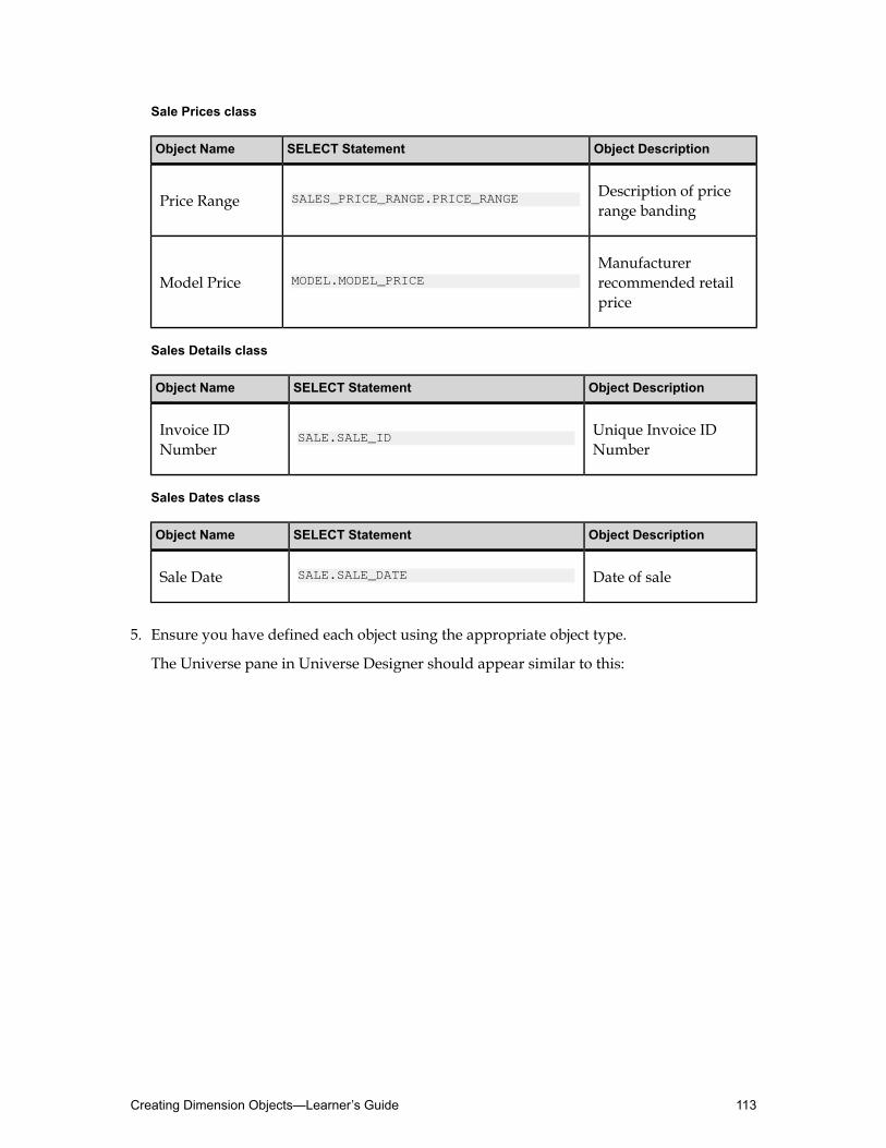
Sale Prices class
Object DescriptionSELECT StatementObject Name
Description of pricerange banding
SALES_PRICE_RANGE.PRICE_RANGEPrice Range
Manufacturerrecommended retailprice
MODEL.MODEL_PRICEModel Price
Sales Details class
Object DescriptionSELECT StatementObject Name
Unique Invoice IDNumber
SALE.SALE_IDInvoice IDNumber
Sales Dates class
Object DescriptionSELECT StatementObject Name
Date of saleSALE.SALE_DATESale Date
5. Ensure you have defined each object using the appropriate object type.
The Universe pane in Universe Designer should appear similar to this:
113Creating Dimension Objects—Learner’s Guide
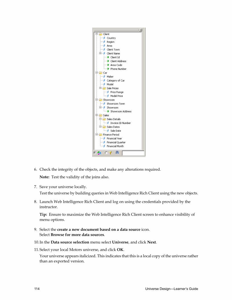
6. Check the integrity of the objects, and make any alterations required.
Note: Test the validity of the joins also.
7. Save your universe locally.Test the universe by building queries inWeb Intelligence Rich Client using the new objects.
8. Launch Web Intelligence Rich Client and log on using the credentials provided by theinstructor.
Tip: Ensure to maximize the Web Intelligence Rich Client screen to enhance visibility ofmenu options.
9. Select the create a new document based on a data source icon.Select Browse for more data sources.
10.In theData source selectionmenu select Universe, and clickNext.
11.Select your local Motors universe, and clickOK.Your universe appears italicized. This indicates that this is a local copy of the universe ratherthan an exported version.
Universe Design—Learner’s Guide114

12.Build a new query using the objects you have created. Drag and drop the objects into theResult Objects pane.
13.Click Run Query to view the final results displayed in the report.
115Creating Dimension Objects—Learner’s Guide

Quiz: Creating dimension objects1. Which of the three types of objects contain aggregate functions that map to statistics in the
database?
2. When you are testing objects, what are the three things for which you need to test?
3. If each object maps to a column or function in a target database, when used in a query, whatkind of statement does the object infer?
Universe Design—Learner’s Guide116

Lesson summaryAfter completing this lesson, you are now able to:
• Define classes and objects• Create classes and objects
117Creating Dimension Objects—Learner’s Guide

Universe Design—Learner’s Guide118

Lesson 5Creating Measure Objects
Lesson introductionThis lesson describes how to create measure objects and test that they produce the correctresults when used in queries.
After completing this lesson, you will be able to:
• Define measure object concepts• Create measure objects• Create delegated measure objects
119Creating Measure Objects—Learner’s Guide

Defining measure object conceptsIn addition to dimension and detail objects you can define measure objects. Measure objectscontain aggregate functions that map to statistics in the database. They represent the metricsby which you want to compare dimensions.
After completing this unit, you will be able to:
• Define measure objects• Determine levels of aggregation
Measure objects concepts
Ameasure object returns numeric information. Measure objects are very flexible because theyare semantically dynamic. This means that the values they return in a query varies dependingon the dimension and detail objects that are used with them.
You can see from the illustration that two separate queries, using the same Sales Revenuemeasure object, but different dimension objects, results in the measure returning differentvalues.
You create a measure object by using an aggregate function in the SELECT definition of theobject. The five basic aggregate functions are:• Sum• Count• Average• Maximum• Minimum
Ameasure object returns numeric data from the database that aggregates up or down accordingto the dimension objects in the query. The most regularly used aggregates are listed above.However, there are others that can be used. The full set of aggregate functions is held in theNumber Functions selection list of the Edit Select Statement dialog box.
Universe Design—Learner’s Guide120

How a measure object infers SQL
When a query uses a measure object with a dimension or detail object, the query definitionautomatically infers a GROUP BY clause in the SELECT statement.
Inference of the GROUP BY clause is dependent on the SQL rule: When the SELECT clause linecontains an aggregate, everything outside of that aggregate in the clause must also appear inthe GROUP BY clause.
That iswhy dimension and detail objectsmust not contain aggregates. Any dimension or detailthat is used in the same query as a measure object is always included in an inferred GROUP BY
clause.
When a query includes only a measure object, the SQL inferred is the same as when the queryuses a dimension object:• The SELECT clause shows the object selected in the query with the syntax including the
aggregate function.
• The FROM clause shows the tables involved in the measure object syntax.
• The WHERE clause identifies the joins among the tables involved.
The query result shows one row of the total revenue value.
In this example, the query includes only the Sales Revenue measure so the inference enginedoes not include a GROUP BY clause in the SQL statement.
When a query uses at least one dimension or detail object and a measure, the inference engineincludes a GROUP BY clause with all the objects except the measure in the SQL Statement:• The SELECT clause shows the object(s) and measure selected in the query with the syntax
including the aggregate function.
• The GROUP BY clause includes all the objects except the aggregate.
In this example, the query includes the Sales Revenue measure and the Country object so theinferred SQL statement includes a GROUP BY clause with the Country.
121Creating Measure Objects—Learner’s Guide

In this example, the query includes two dimensions (Country and Region) so the inferenceengine includes both dimensions in the GROUP BY clause. As a result, the values returned forthe Sales Revenue measure object are aggregated to a lower level, the Region. This mechanismin the inference engine allows the measure objects to adapt dynamically to other, associatedobjects.
The query process
How do the Business Objects end-user querying tools process the measure object in a query,and how do the values get projected?
There are two levels of aggregation in the query process:• Aggregation at SELECT level
• Aggregation at projection level
Universe Design—Learner’s Guide122

Aggregation at SELECT level
Aggregation at SELECT level occurs first in the query process:• The user creates a query.
• Web Intelligence Rich Client defines the SQL from the query and sends a SELECT statementto the target database.
• The data is returned to the microcube. The first level of aggregation now takes place in themicrocube.
• The results are projected in the query. The microcube projects the aggregated data onto thereport, the SQL statement is inferred against the database, and the results are returned tothe microcube.
Aggregation at projection level
When you run a query, the result set of the SELECT statement is stored in the microcube. Alldata then held in the microcube is projected into a block (the table or chart in the report).Therefore, because data is projected from the lowest level held in the microcube, no projectionaggregation takes place.
However, when you edit the table, for example, by removing a column, and therefore projectonly partial data from the microcube, aggregation is required to show measure values at ahigher level. The data in the microcube remains unchanged.
123Creating Measure Objects—Learner’s Guide
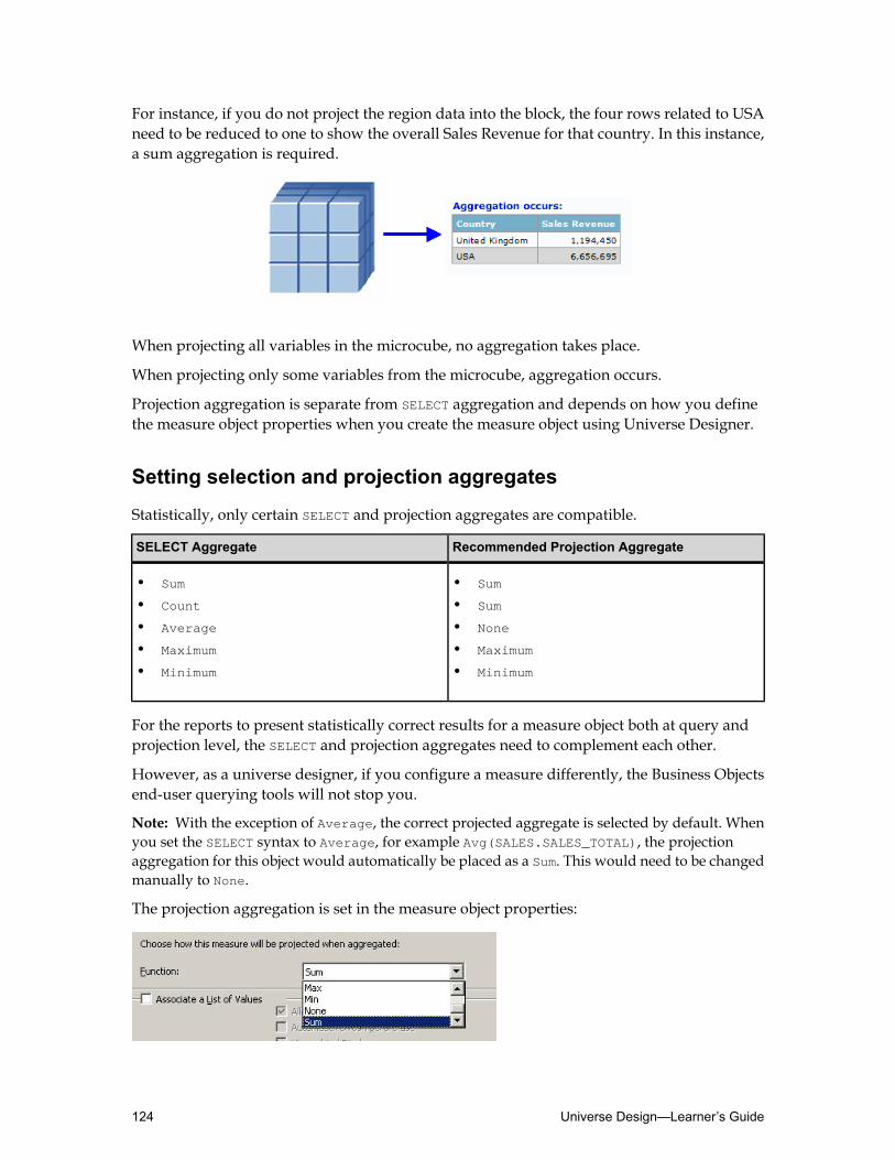
For instance, if you do not project the region data into the block, the four rows related to USAneed to be reduced to one to show the overall Sales Revenue for that country. In this instance,a sum aggregation is required.
When projecting all variables in the microcube, no aggregation takes place.
When projecting only some variables from the microcube, aggregation occurs.
Projection aggregation is separate from SELECT aggregation and depends on how you definethe measure object properties when you create the measure object using Universe Designer.
Setting selection and projection aggregates
Statistically, only certain SELECT and projection aggregates are compatible.
Recommended Projection AggregateSELECT Aggregate
• Sum• Sum
• •Count Sum
•• NoneAverage
• •Maximum Maximum
•• MinimumMinimum
For the reports to present statistically correct results for a measure object both at query andprojection level, the SELECT and projection aggregates need to complement each other.
However, as a universe designer, if you configure a measure differently, the Business Objectsend-user querying tools will not stop you.
Note: With the exception of Average, the correct projected aggregate is selected by default. Whenyou set the SELECT syntax to Average, for example Avg(SALES.SALES_TOTAL), the projectionaggregation for this object would automatically be placed as a Sum. This would need to be changedmanually to None.
The projection aggregation is set in the measure object properties:
Universe Design—Learner’s Guide124

Creating measure objectsAfter definingmeasure objects, the next step is to understand how to create and employmeasureobjects in the universe, and test them in Web Intelligence Rich Client.
After completing this unit, you will be able to:
• Create measure objects• Test measure objects in Web Intelligence Rich Client
Measure objects
You create measure objects in the same way that you create a dimension or detail object. Theycan be created using the automatic or manual method.
It is recommended that you groupmeasure objects together in separate classes fromdimensionand detail objects, if they are generic. In other words, if they can be used in the same query asany dimension and detail object in the universe, then they are considered generic, and youmust group them in separate classes.
If they are only compatible with certain objects, however, then you may want to place them inthe same class as those objects, to indicate this fact to the report designers.
It is important to remember the following when you create measure objects:
In the Definition tab
• The Type field must be set toNumber.
• The Select field must include an aggregate function.
Tip: It is best to use the Edit Select dialog box to insert the SELECT clause content of a measureas you can then use the Function and Columns selection lists.
Note: When an aggregate function is used in the Edit Select dialog box, the qualification isautomatically set toMeasure type.
In the Properties tab
• The qualification must be set as aMeasure type.
• In the Function field, make sure the function you use is compatible with the aggregate usedin the SELECT statement.
• Ameasure object should not have a list of values associatedwith it. Therefore, theAssociatea List of Values check box should be unchecked.
125Creating Measure Objects—Learner’s Guide

Testing measure objects
When you test ameasure, youmust be far more rigorous in your checks thanwith a dimensionor detail object. This is because you have to check that the values of the measure aggregatecorrectly both at SELECT and projection level.
The three elements to testing a dimension or a detail object are:1. Check that the objects exist.
2. Check the inferred SQL.
3. Check the query results.
For measure objects, the additional elements are:• Repeat with the other dimensions.
• Make a query with a minimum of two dimensions and a measure.
• To validate the accuracy of the measure aggregate, it is recommended that you test it withat least three separate queries.
Testing measures at SELECT level
To test the inferred SELECT statements for ameasure object, youmustmake at least two separatequeries using different dimension objects to produce different levels of aggregation. Three ormore queries are preferable.
In each instance, you must check the following:
Universe Design—Learner’s Guide126

• The inferred SQL of the query. In particular, you should check the GROUP BY clause has beeninferred correctly.
Note: If it has not been inferred at all, it is likely that you have set a calculation and not anaggregate in the Select field of the measure object properties.
• The results of the query. Check that the query produces the correct results.
Testing measures at projection level
To test for projected aggregation, you need to build a query containing at least two dimensionobjects, as well as the measure object you are testing. This allows you to project from otherthan the lowest level of data held in the microcube and therefore test aggregation.
Activity: Creating and testing measure objects
Objective
• Create and test measure objects.
Instructions
1. Create the following subclass in the Sales class:• Sales Figures
2. Create measure objects in the new Sales Figures subclass as identified in the tables below.The SQL code for the SELECT properties of each object has been specified for you. However,you need to determine the appropriate projection function aggregate.
127Creating Measure Objects—Learner’s Guide

Sales Figures class
Object DescriptionSELECT StatementObject Name
Total Sale InvoiceRevenue
sum(SALE_MODEL.SALE_QTY * MODEL.MODEL_PRICE * ((100 - SALE.SALE_DISCOUNT) / 100))
Sales Revenue
Total Cost of CarSales
sum(SALE_MODEL.SALE_QTY * MODEL.MODEL_COST)Cost of Car Sales
Total Number ofCars Sold
sum(SALE_MODEL.SALE_QTY)Number of CarsSold
Tip: When using theNumber of Sars Sold, and Cost of Car Sales objects, ensure that theresult is always restricted to Sales data.
3. Create measure objects in the classes as identified in the tables below. The SQL code for theSELECT properties of each object has been specified for you.However, you need to determinethe appropriate projection function aggregate.
Universe Design—Learner’s Guide128
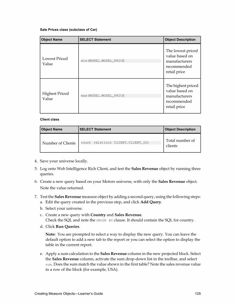
Sale Prices class (subclass of Car)
Object DescriptionSELECT StatementObject Name
The lowest pricedvalue based on
min(MODEL.MODEL_PRICELowest PricedValue manufacturers
recommendedretail price
The highest pricedvalue based on
max(MODEL.MODEL_PRICEHighest PricedValue manufacturers
recommendedretail price
Client class
Object DescriptionSELECT StatementObject Name
Total number ofclients
count (distinct CLIENT.CLIENT_ID)Number of Clients
4. Save your universe locally.
5. Log onto Web Intelligence Rich Client, and test the Sales Revenue object by running threequeries.
6. Create a new query based on your Motors universe, with only the Sales Revenue object.Note the value returned.
7. Test theSales Revenuemeasure object by adding a second query, using the following steps:a. Edit the query created in the previous step, and click Add Query.b. Select your universe.c. Create a new query with Country and Sales Revenue.
Check the SQL and note the GROUP BY clause. It should contain the SQL for country.d. Click Run Queries.
Note: You are prompted to select a way to display the new query. You can leave thedefault option to add a new tab to the report or you can select the option to display thetable in the current report.
e. Apply a sum calculation to the Sales Revenue column in the new projected block. Selectthe Sales Revenue column, activate the sum drop-down list in the toolbar, and selectsum. Does the summatch the value shown in the first table? Note the sales revenue valuein a row of the block (for example, USA).
129Creating Measure Objects—Learner’s Guide

8. Test the Sales Revenuemeasure object by creating a third query, using the following steps:a. Edit the second query and then click Add Query.b. Create a new query with Country, Region, and Sales Revenue.c. Check the SQL and note the GROUP BY clause. It should now contain the SQL for country
and region. Click Run Queries.d. Apply a break to theCountry column and apply a sum calculation to the Sales Revenue
column of the new projected block. Does the country group sum match the value of thenoted block row in the second table (for example, USA)?
e. Edit the query. Change the projection to the block from the microcube by removing theRegion column from the block. Does it aggregate to country level correctly?
f. Edit the query again. Change the projection to the block from themicrocube by removingthe Country column from the block. Does it aggregate to the total sales revenue levelcorrectly?
g. Edit the query again. Add the Showroom andMaker objects.h. Using drag and drop, insert two new tables, one to showShowroom andSales Revenue,
and the other to showMaker and Sales Revenue, and apply a sum to both tables. Notethat the total values remain the same. The final version of the report should look similarto this:
9. Test the other measure objects in Web Intelligence Rich Client.
Universe Design—Learner’s Guide130

Creating delegated measure objectsUniverse Designer allows designers to create measures whose calculation is delegated to thedatabase. These are called "delegated smart measures".
After completing this unit, you will be able to:
• Define delegated measure and how they work• Understand how you benefit from using delegated measures• Know how to use delegated measures appropriately• Apply best practices when using delegated measures
What is a delegated measure?
A delegated measure is a measure that delegates its aggregation calculation to the database.
The universe designer defines a delegatedmeasure in the universe tomake it available to reportusers for ad hoc reporting or for viewing reports built on that universe.
A universe designer can create a delegated measure when conventional Web Intelligence orWeb Intelligence Rich Client aggregation does not provide an accurate result for the measure,such as for:• Complex averages, such as Weighted averages (an average of a percentage).• Ratios.• Other measures that do not aggregate along all the dimensions in a report.• OLAP sources where measure aggregations are already available in the OLAP cube.
The delegated measure is then available to report designers in Web Intelligence and WebIntelligence Rich Client.
Delegated measures are available for all relational and OLAP data sources.
The benefits of delegated measure
The delegated measure represents an extension of Web Intelligence andWeb Intelligence RichClient calculations by supporting aggregation within the database and makes non-additivemeasures available within the universe.
You benefit from delegated measures because they:• Increase Web Intelligence and Web Intelligence Rich Client querying efficiency.• Make non-additive measures available within the universe.• Use database-specific syntax to improve performance and provide optimization on the
internal architecture of all vendors.• Extend support of calculations beyond Web Intelligence and Web Intelligence Rich Client
documents.
131Creating Measure Objects—Learner’s Guide

How does the delegated measure work?
By default, Web Intelligence andWeb Intelligence Rich Client calculate measures based on theobjects used within the query. The dimensions used in the query are called a grouping set.
The delegatedmeasure calculates the aggregation of the measure for any subset of dimensionsrequired in the report.
For example, a query that retrieves the dimensions Country, Region, Maker, Year, Number ofCars Sold and Average Sales Total would, by default, calculate the Number of Cars Sold andAverage Sales Total for that grouping set.
However, when you format your report, if you want to present the Number of Cars Sold andAverage Sales Total for Region and Maker, Web Intelligence does not know how to calculatethe correct Average Sales Total for these smaller entities.
The delegated measure, on the other hand, calculates the measures for all subsets of thedimensions in the report. Thus, it would calculate Number of Cars Sold and Average SalesTotal per:• Country• Country and Year• Country, Region, and Year• Country, Region, Maker, and Year
What happens when changes are made to the report?
When the report changes, the delegated measure updates the grouping set accordingly:• When users add to the grouping set, the value #TOREFRESH appears to indicate that the
value is missing and they need to refresh the report to see the measure.• When users save their report, it removes unused grouping sets.
Using a delegated measure as a weighted average
A report designer wants to calculate the average sales total per region, and also for all regions.
The universe designer has created a measure called Average Sales Total that calculates theaverage of the sales totals.
When the user runs this in a Web Intelligence Rich Client query, together with Region, theaverage sales total per each region is calculated.
In the report, the user then wants to calculate the average sales total level for all regions, andadds an average calculation on the Average Sales Total column.
Universe Design—Learner’s Guide132

A new row appears at the bottom of the table and this row displays the average sales total forall regions.
This appears accurate, but it is not.Web Intelligence Rich Client is adding up the values shownin the Average Sales Total column and then dividing them up by six, since there are six regionsavailable. The values in the Average Sales Total column are already calculated averages, soWeb Intelligence is actually calculating the average of averages.
What is required here is aweighted average, as some regions havemore car sales revenue returnsthan others. The sales total value returned by those regions with more sales returns needs tocount more heavily than those regions with fewer returns.
When adding the Number of Cars sold figure to the query, you see here that the number ofcars sold per region varies considerably. Sixty-eight cars were sold in the West Coast, whileonly thirteen in the East Coast.
WhenWeb Intelligence Rich Client calculates the overall average sales total, it cannot take intoaccount the fact that theWest Coast should havemore weight in the calculation of the average.Web Intelligence Rich Client does not have access to the detailed data, just to the regionalaverage value, returned by the Average Sales Total measure.
133Creating Measure Objects—Learner’s Guide
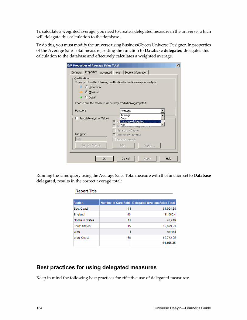
To calculate aweighted average, you need to create a delegatedmeasure in the universe, whichwill delegate this calculation to the database.
To do this, youmustmodify the universe using BusinessObjectsUniverseDesigner. In propertiesof the Average Sale Total measure, setting the function toDatabase delegated delegates thiscalculation to the database and effectively calculates a weighted average.
Running the samequery using theAverage Sales Totalmeasurewith the function set toDatabasedelegated, results in the correct average total:
Best practices for using delegated measures
Keep in mind the following best practices for effective use of delegated measures:
Universe Design—Learner’s Guide134

• Use a delegatedmeasurewhen report usersmanipulate themeasures in reports.When theyonly need to refresh, view and print their reports, the calculationmay be simpler to performin the report.
• Use a delegated measure to replace multiple query aggregates.• Use a delegated measure on calculations that could give inaccurate results when calculated
in the report (such as a complex average).• Use a delegated measure for measures requiring division.• When you create the delegatedmeasure in the universemake sure that in the Edit Properties
dialog box for themeasure, on theDefinition tab, you enter identifying text in theDescriptionfield. This ensures report designers can quickly recognize a delegated measure when theyglide their mouse over it in a query
When are delegated measures inappropriate?
Donot use delegatedmeasureswhen you apply a filter to an aggregated value fromyour queryand further aggregate it within the report.
Web Intelligence cannot determine how the filter affects the calculation of the delegatedmeasureand, instead, returns the cell error code #UNAVAILABLE.
For example, do not use delegated measures when there is a:• Report filter on a dimension that is not in the dimensional context.• Report filter on the formula.• Formula in the dimensional context of the measure.
However, for drill filters and for simple filters combinedwith AND at the first level of drilling,the context takes the related dimension into account.
Also, do not use a delegated measure when a standard measure works.
Activity: Creating and using a delegated measure
Objectives
• Create a delegated measure in Universe Designer.• Use a delegated measure in Web Intelligence Rich Client.
Instructions
1. In Universe Designer, open your Motors universe file.
2. In the Sales Figures class, create a newmeasure calledAverage Sales Totalwith the followingsyntax:avg(SALE.SALES_TOTAL)
In the Properties tab, set the aggregation function toNone.
3. Save the universe and log onto Web Intelligence Rich Client.
4. Create a new query using theRegion and theAverage Sales Total objects. ClickRunQuery.
135Creating Measure Objects—Learner’s Guide
Contact For Any SAP Module Materials : [email protected] ll VISIT: www.sapcertified.com ll

5. Select the Average Sales Total column and select the average function from the toolbar.Activate the sum drop-down list and select average.Evaluate the result.
6. Edit the query and addNumber of Cars Sold.Evaluate the average value that is shown at the bottom of theAverage Sales Total column.Does this reflect the correct average per Region?
7. Return to Universe Designer and copy the Average Sales Total object and paste it in thesame class. Name the copied objectDelegated Sales Total Average.Ensure theAssociate a List ofValues option for theDelegated Sales Total Averagemeasureis cleared.
8. In the Properties tab, set the aggregation function toDatabase delegated.Save your universe locally.
9. Return to Web Intelligence Rich Client.
Tip: To ensure that your newversion of your universe is available, go toTools➤Universesand refresh the list.
10.Create a new query with the Region, Average Sales Total, and theDelegated Sales TotalAverage objects.
11.Add an average to the Average Sales Total column, as done in step 5.
12.Drag theDelegated Sales Totalmeasure object from theData tab and position it in the cellat the bottomof theDelegated Sales Total column.Drop theDelegated Sales Totalmeasureobject in the cell at the bottom of this column.
Note that the cell now displays a text string: #TOREFRESH.
This indicates that the average is not calculated byWeb Intelligence Rich Client, but it mustbe calculated by the database.
You need to refresh the document to retrieve the calculated results from the database.
13.Click Refresh Data.
Universe Design—Learner’s Guide136
Contact For Any SAP Module Materials : [email protected] ll VISIT: www.sapcertified.com ll

You see here that the average calculated by the database does not return the same value asthe value calculated by Web Intelligence Rich Client.
Because the database has access to the detailed data concerning all satisfaction levels inthese regions, the result is based on a weighted average. The database is able to take intoaccount the difference in numbers of customers per region.
137Creating Measure Objects—Learner’s Guide

Quiz: Creating measure objects1. Measure objects are very flexible because they are semantically dynamic. What does this
mean?
2. Measure objects are created in the same way as a dimension or detail object. However, theobject properties differ in two ways. What are they?
Universe Design—Learner’s Guide138

Lesson summaryAfter completing this lesson, you are now able to:
• Explain measure object concepts• Create measure objects• Create delegated measure objects
139Creating Measure Objects—Learner’s Guide

Universe Design—Learner’s Guide140

Lesson 6Resolving Loops in a Universe
Lesson introductionThis lesson describes loops, a particular type of join issue that can arise as you create joinsbetween tables in your schema. It explains how you can detect and resolve loops to ensure thatthe join paths taken by queries run on the universe return correct results.
After completing this lesson, you will be able to:
• Understand loops• Resolve loops using aliases• Resolve loops using contexts
141Resolving Loops in a Universe—Learner’s Guide

Understanding loopsA loop is a join path issue that arises from theway that tables are related in a relational database.Loops can produce instances where a query returns too few rows of data.
After completing this unit, you will be able to:
• Understand the causes of loops• Detect loops in a universe structure
Recognizing loops
A loop exists when the joins between tables form a closed path.
For example, in the table layout above, the designer has added joins between the tablesShowroom and Country to create two linked sets of information:• One set links the car sale details, the client, the client’s region and the client’s country of
residence.
• The other set links the car sale details, the showroom, and the country where the showroomis located.
Together, these joins form a loop.
Problems caused by loops
Suppose users of theMotors universe want to produce reports showing the revenue generatedby car sales to clients, including both the location of the showroomwhere the cars are sold andthe address (including country) of the clients.
Universe Design—Learner’s Guide142

The designer adds the tables needed to provide this information and creates the joins as shownin the previous example. The designer has also created objects for the Showroom Country,Client Country, and Sales Revenue.
If the loop was allowed to remain and a query was run using the Showroom Country, ClientCountry and Sales Revenue objects, the report results would be incorrect. The report wouldsuggest that only clients from the US bought cars in the US showrooms, and only clients fromthe UK bought cars in the UK showrooms. However, the report would not show any clientsfrom any other countries.When you know that there are clients from other countries, this resultindicates that there is a problem with the report.
Loops in a universe schema and not in the database
In a database, multiple paths between tables can be valid and implemented to meet specificuser requirements. When each path is included individually in a query, it returns a distinct setof results.
However, a schema that you design in Universe Designer often needs to allow queries thatinclude more than one path, which a relational database may not be designed to handle. As aresult, the information returned can be incorrect.
The rows that are returned are an intersection of the results for the path, so fewer rows arereturned than expected. It is often difficult to determine the problem when you examine theresults.
What is the loop doing?
The joins in the Structure pane are used to create the WHERE clause in the inferred SQL of aquery. Joins restrict the data that is returned by the query. In a loop, the joins apply morerestrictions than the designer intended, and incorrect data is returned.
This is an example of a WHERE clause created by a loop:WHERE{COUNTRY.COUNTRY_ID=SHOWROOM.COUNTRY_ID}AND {COUNTRY.COUNTRY_ID=REGION.COUNTRY_ID }AND {REGION.REGION_ID=CLIENT.REGION_ID }AND {CLIENT.CLIENT_ID=SALE.CLIENT_ID }AND {SHOWROOM.SHOWROOM_ID=SALE.SHOWROOM_ID }AND {SALE.SALE_ID=SALE_MODEL.SALE_ID }AND {SALE.SALE_TYPE= 'S' }
Notice that the two joins at the top of the SQL statement are both applying a restriction to theCountry table, which is serving two purposes:• It is being used as the Lookup for the Showroom Country.
• It is also the Lookup for the Client Country.
This creates a restriction so that data is returned onlywhen the ShowroomCountry is the sameas the Client Country. Consequently, the report shows only the revenue generated byUS clientsin the US showrooms and by UK clients in the UK showrooms. In summary, while the aboveloop infers legitimate SQL, the results do not include all intended values. Therefore, a query
143Resolving Loops in a Universe—Learner’s Guide
Contact For Any SAP Module Materials : [email protected] ll VISIT: www.sapcertified.com llContact For Any SAP Module Materials : [email protected] ll VISIT: www.sapcertified.com llContact For Any SAP Module Materials : [email protected] ll VISIT: www.sapcertified.com llContact For Any SAP Module Materials : [email protected] ll VISIT: www.sapcertified.com llContact For Any SAP Module Materials : [email protected] ll VISIT: www.sapcertified.com llContact For Any SAP Module Materials : [email protected] ll VISIT: www.sapcertified.com llContact For Any SAP Module Materials : [email protected] ll VISIT: www.sapcertified.com llContact For Any SAP Module Materials : [email protected] ll VISIT: www.sapcertified.com llContact For Any SAP Module Materials : [email protected] ll VISIT: www.sapcertified.com llContact For Any SAP Module Materials : [email protected] ll VISIT: www.sapcertified.com llContact For Any SAP Module Materials : [email protected] ll VISIT: www.sapcertified.com llContact For Any SAP Module Materials : [email protected] ll VISIT: www.sapcertified.com llContact For Any SAP Module Materials : [email protected] ll VISIT: www.sapcertified.com llContact For Any SAP Module Materials : [email protected] ll VISIT: www.sapcertified.com ll

on a universe involving such a loop returns misleading data. To avoid this, the loop must beresolved.
Resolving loops
Loops are an inherent problem when writing SQL statements. There are various techniqueswithin SQL that you can apply to resolve loops.
How Universe Designer deals with loops
There are automatic methods built into Universe Designer that can be used to identify andresolve almost all loop problems. The two main methods of resolving loops are:• Aliases
• Contexts
Loops can be resolved by creating aliases and contexts manually. However, depending on thecomplexity of a universe, this can be a cumbersome task. There is functionality built intoUniverseDesigner that allows for automatic detection and resolution of loops. This functionalitycan only be reliable if cardinality has been defined correctly for each join in the universe.Furthermore, due to performance implications, it is recommended that all cardinality be setmanually at the time each join is created.
Universe Design—Learner’s Guide144
Resolving loops using aliasesOne way to solve a loop in the universe structure is to create an alias table.
After completing this unit, you will be able to:
• Describe aliases• Resolve loops using aliases• Resolve self-referencing join loops using aliases
About aliases
An alias breaks a loop by using the same table twice in the same query for a different purpose.The alias is identical to the base table but with a different name. The data in the alias is exactlythe same as the original table, but the different name tricks SQL into using the same databasetable for two different purposes.
The Country table has already been identified as a shared lookup table because it is servingtwo purposes in the query you are trying to run (providing data for the Client Country andalso for the Showroom Country). In the example above, you can see the Country table joinedto the Region table for the Client side of the query. The Country table also is the Showroomtable for the Showroom side of the query.
Note: Another way of spotting the problem table in a loop is that it only has the one end ofthe one-to-many joins going into it. Check the other tables in the loop. If you find no otherswith only one-end joins, the loop can be resolved using an alias, assuming there are no othertables joined to country.
To resolve the loop, you need to use the same table (the Country table) twice in the same querywhen it is being used for different purposes. However, you cannot do this in SQL unless youcreate an Alias table.
You can resolve the loop satisfactorily by creating only one alias table in the example we havebeen using. The Region join uses the original Country table, while the Showroom join uses thealias table. However, you could create a separate alias table for each join in the original table.In the past, thiswas necessary for some relational databases. Today, it is not necessary.However,some universe designers prefer to alias both tables.
Detecting loops and inserting aliases
The Universe Designermodule has automatic tools that detect loops and create aliases for you.
You can use theDetect Loops orDetect Aliases toolbar icons, to automatically detect andindicate the tables causing loops in the active universe.Detect Aliases proposes candidatetables that you can edit, and insert in the schema.
Note: Before usingDetect Aliases, verify that all the tables in schema are linked by joins, andthat all cardinalities are set.
145Resolving Loops in a Universe—Learner’s Guide

To detect loops using the automatic detection tool
1. Click theDetect Loop button.
The system highlights the loop in the Structure pane, and displays the Loop Detectiondialog box.
2. The Loop 1/1 indicates how many loops have been detected. If there are others, you canuse the forward and back arrowbuttons to check each loop. Themessage beneath the buttonsindicates (in this case) that the loop can be resolved with an alias.
3. Click Insert Alias in the Loop Detection dialog box.
Universe Designer automatically creates an alias for the required table. You may need tomove the new alias table so that you can see the Structure pane.
Note: The original table name shows up in brackets in the alias table header.
4. Close the Loop Detection dialog box.
The Structure pane look similar to this:
Universe Design—Learner’s Guide146
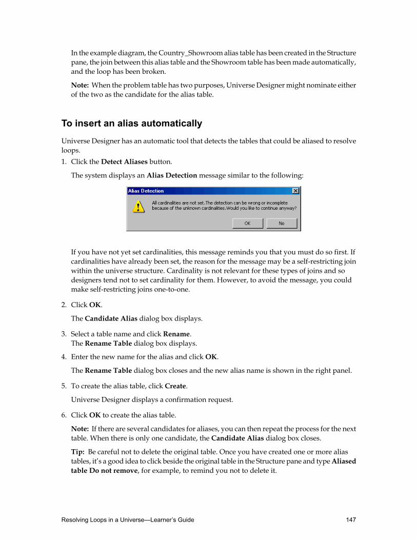
In the example diagram, the Country_Showroomalias table has been created in the Structurepane, the join between this alias table and the Showroom table has beenmade automatically,and the loop has been broken.
Note: When the problem table has two purposes, Universe Designermight nominate eitherof the two as the candidate for the alias table.
To insert an alias automatically
Universe Designer has an automatic tool that detects the tables that could be aliased to resolveloops.1. Click theDetect Aliases button.
The system displays an Alias Detectionmessage similar to the following:
If you have not yet set cardinalities, this message reminds you that you must do so first. Ifcardinalities have already been set, the reason for the message may be a self-restricting joinwithin the universe structure. Cardinality is not relevant for these types of joins and sodesigners tend not to set cardinality for them. However, to avoid the message, you couldmake self-restricting joins one-to-one.
2. ClickOK.
The Candidate Alias dialog box displays.
3. Select a table name and click Rename.The Rename Table dialog box displays.
4. Enter the new name for the alias and clickOK.
The Rename Table dialog box closes and the new alias name is shown in the right panel.
5. To create the alias table, click Create.
Universe Designer displays a confirmation request.
6. ClickOK to create the alias table.
Note: If there are several candidates for aliases, you can then repeat the process for the nexttable. When there is only one candidate, the Candidate Alias dialog box closes.
Tip: Be careful not to delete the original table. Once you have created one or more aliastables, it’s a good idea to click beside the original table in the Structure pane and typeAliasedtable Do not remove, for example, to remind you not to delete it.
147Resolving Loops in a Universe—Learner’s Guide
To insert an alias manually
Instead of using the loop detection or alias detection tools, you can create the alias manually.1. Select the table for which you want an alias by clicking the table header.
2. Insert an alias using one of the following methods:• Click the Insert Alias button.• Right-click the table and select Alias from the right-click menu.
3. Enter the new name for the alias table and clickOK.
This creates an alias table for the selected table.
Note: The original table name appears in brackets in the alias table header.
4. Remove the appropriate join from the original table.
5. Reset the join to the alias table.
6. Set the cardinality for the join.
The Structure pane should now look the same as when using the first method, the loopdetection tool.
7. If there are several candidates for aliases, you can then repeat the process for the next table.When there is only one candidate, the Candidate Alias dialog box closes.
Tip: Be careful not to delete the original table. Once you have created one or more aliastables, it’s a good idea to click beside the original table in the Structure pane and typeAliasedtable Do not remove, for example, to remind you not to delete it.
Redefining objects
When you create an alias table, check that any existing objects that are defined from the originaltable still refer to the right table. They may need to be defined from the alias table to infer thecorrect SQL and get the correct result.
Finding objects defined from a table
In a simple universe, it is not difficult to find the objects that have been defined from a table.There is a utility in Universe Designer that allows you to easily determine all existing objectsthat point to a single table in the structure of the universe.
To find objects defined from a table
Universe Designer provides an option to assist in finding the relevant objects.1. Right-click the header of the original table in the Structure pane.
2. Choose View associated objects from the right-click menu. This highlights all the objectsthat were defined from the original table in the Universe pane.
Universe Design—Learner’s Guide148
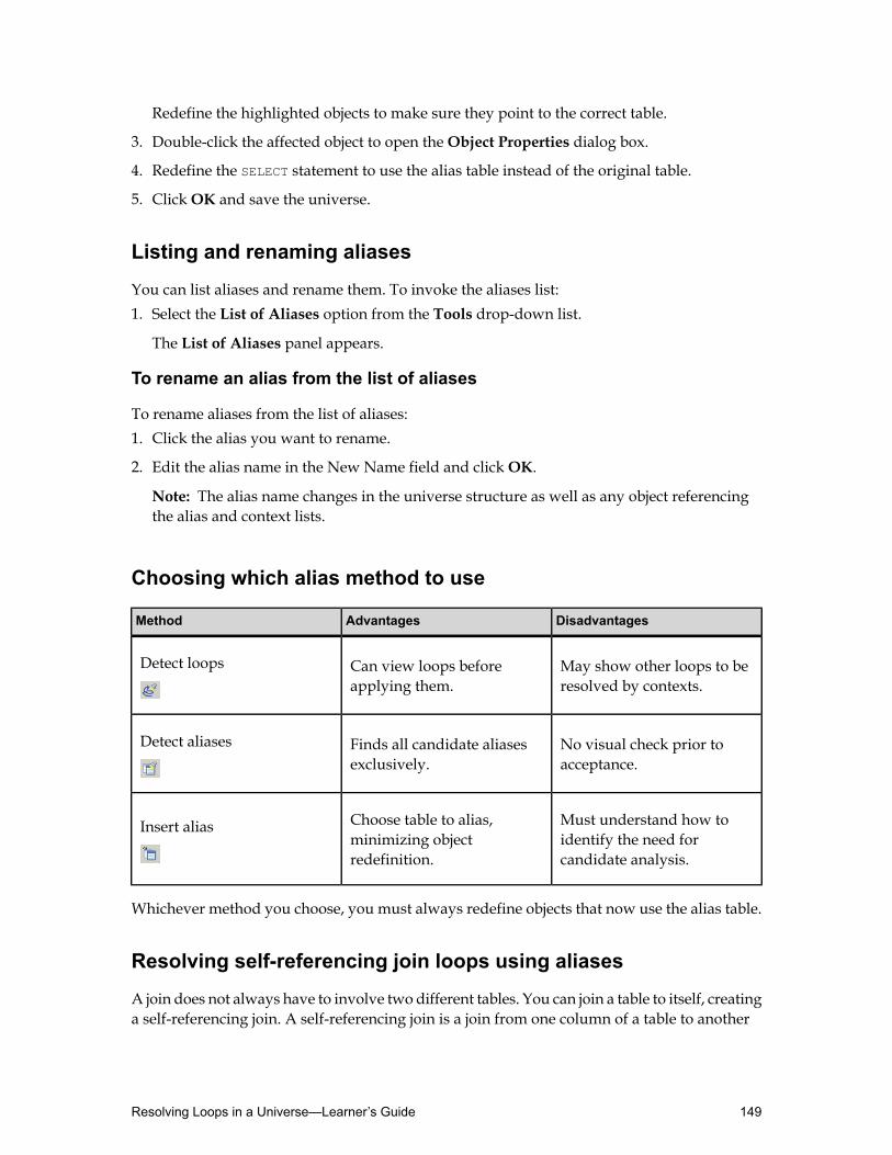
Redefine the highlighted objects to make sure they point to the correct table.
3. Double-click the affected object to open theObject Properties dialog box.
4. Redefine the SELECT statement to use the alias table instead of the original table.
5. ClickOK and save the universe.
Listing and renaming aliases
You can list aliases and rename them. To invoke the aliases list:1. Select the List of Aliases option from the Tools drop-down list.
The List of Aliases panel appears.
To rename an alias from the list of aliases
To rename aliases from the list of aliases:1. Click the alias you want to rename.
2. Edit the alias name in the New Name field and clickOK.
Note: The alias name changes in the universe structure as well as any object referencingthe alias and context lists.
Choosing which alias method to use
DisadvantagesAdvantagesMethod
May show other loops to beresolved by contexts.
Can view loops beforeapplying them.
Detect loops
No visual check prior toacceptance.
Finds all candidate aliasesexclusively.
Detect aliases
Must understand how toidentify the need forcandidate analysis.
Choose table to alias,minimizing objectredefinition.
Insert alias
Whichever method you choose, you must always redefine objects that now use the alias table.
Resolving self-referencing join loops using aliases
A join does not always have to involve two different tables. You can join a table to itself, creatinga self-referencing join. A self-referencing join is a join from one column of a table to another
149Resolving Loops in a Universe—Learner’s Guide

column of the same table. Joining a table to itself can be useful when you want to comparevalues in a column to other values in the same column.
A classic example of when such a join is required is in a situation whereby you want to reporton the hierarchical structure of an organization via a Personnel database. In such a situation,it is most probable that all employee records are held in a single table, irrespective of status.Therefore, a self-referencing join is required to report on the hierarchical relationship betweenthose employees.
For example, in theMotors database there is an employees table that contains columns as shownbelow:
Each employee is uniquely identified by the Emp_Id field, and each employee has a manager,who is identified by the Emp_Mgr_Id field.However, themanagers are themselves employees,and the table therefore contains a hierarchical structure.
If youwant to add a join to link each employeewith their respectivemanager, the obviouswayis to link the Emp_Mgr_Id field to the Emp_Id field, as in this example:
The code used to identify the manager (Emp_Mgr_Id ) is itself an employee code. You cantherefore use it to look up the Emp_Id codes in the Employee table and identify the manager’sname.
This is effectively a loop, as the path forms a closed circuit. However, you cannot resolve it byusing the usualmethod of detecting the cardinalities and then detecting aliases. This is becausethe cardinality detection tool cannot work on a self-referencing join. Moreover, a structureexpressed this way does not infer the correct SQL.
Universe Design—Learner’s Guide150

To resolve a self-referencing join with an alias
1. Right-click the table header and choose Alias from the right-click menu.
2. Enter an appropriate alias table name.
3. ClickOK.
4. Draw the join between the original table and its alias.
5. Double-click the join.The Edit Join dialog box opens.
6. Set the cardinality for the join.
7. The self-referencing join has been resolved. You can create separate objects for both tables.
Activity: Using aliases to resolve loops
Objectives
• Resolve loops by creating alias tables• Test your results in Web Intelligence Rich Client
Instructions
In this activity new tables, new joins, cardinality, are inserted into yourMotors universe. Theseresult in loops in your universe structure. Resolve these loops and test the results in WebIntelligence Rich Client.1. Insert the following join and set its cardinality.
• COUNTRY.COUNTRY_ID = SHOWROOM.COUNTRY_ID
2. Use theDetect Loop toolbar button to test for loops in your universe. To solve the loopsthat you have detected by creating alias tables, press the Insert Aliases button in the LoopDetection dialog box, or use the Insert Alias toolbar button and create two alias tablescalled:• COUNTRY_SHOWROOM
• COUNTRY_REGION
• COUNTRY_MAKER
3. Disconnect the original COUNTRY table from the other tables and use the alias tables toredefine the joins as follows:• COUNTRY_SHOWROOM.COUNTRY_ID = SHOWROOM.COUNTRY_ID
• COUNTRY_REGION.COUNTRY_ID = REGION.COUNTRY_ID
• COUNTRY_MAKER.COUNTRY_ID = MAKER.COUNTRY_ID
Note: Ensure that the join cardinality for the last join is set to one-to-many (1-N).
4. Create the following object in the Showroom class:
151Resolving Loops in a Universe—Learner’s Guide
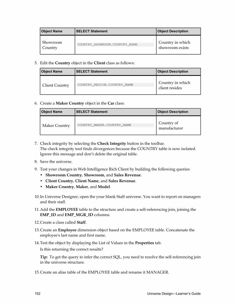
Object DescriptionSELECT StatementObject Name
Country in whichshowroom exists
COUNTRY_SHOWROOM.COUNTRY_NAMEShowroomCountry
5. Edit the Country object in the Client class as follows:
Object DescriptionSELECT StatementObject Name
Country in whichclient resides
COUNTRY_REGION.COUNTRY_NAMEClient Country
6. Create aMaker Country object in the Car class:
Object DescriptionSELECT StatementObject Name
Country ofmanufacturer
COUNTRY_MAKER.COUNTRY_NAMEMaker Country
7. Check integrity by selecting the Check Integrity button in the toolbar.The check integrity tool finds divergences because the COUNTRY table is now isolated.Ignore this message and don’t delete the original table.
8. Save the universe.
9. Test your changes in Web Intelligence Rich Client by building the following queries:• Showroom Country, Showroom, and Sales Revenue.• Client Country, Client Name, and Sales Revenue.• Maker Country,Maker, andModel.
10.In Universe Designer, open the your blank Staff universe. You want to report on managersand their staff.
11.Add the EMPLOYEE table to the structure and create a self-referencing join, joining theEMP_ID and EMP_MGR_ID columns.
12.Create a class called Staff.
13.Create an Employee dimension object based on the EMPLOYEE table. Concatenate theemployee's last name and first name.
14.Test the object by displaying the List of Values in the Properties tab.Is this returning the correct results?
Tip: To get the query to infer the correct SQL, you need to resolve the self-referencing joinin the universe structure.
15.Create an alias table of the EMPLOYEE table and rename it MANAGER.
Universe Design—Learner’s Guide152

Join the tables as shown below:
16.In the Staff class, create aManagers dimension object based on the MANAGER alias table.Concatenate the manager's last name and first name columns.
17.Check the integrity of the Staff universe with all except the cardinality options checked.Resolve any relevant divergence.
Tip: You should not find any divergences.
18.Save your Staff universe, and test the results in Web Intelligence Rich Client as follows:1. Run a query usingManager and Employee. Add a count on both columns.
2. Add a query with only theManager object. Add a count. Is this the correct value?
3. Open your Staff universe in Universe Designer and edit theManager object. To ensurethat the data is restricted to only manager data, use the Tables button. Select theEMPLOYEE table, to force the object to use the join between the table and restrict thedata.
4. Test the result, creating a new query with only theManager object. It returns the correctnumber of managers.
5. Edit the query and add Employee. Run and display the count. There are 26 rows. Why?The join restricts the data to look only for employees that havemanagers. However, thereis a manager that does not have a manager, and is now excluded.
6. Open your Staff universe in Universe Designer and add an outer join on theMANAGERtable side.
7. Save the changes and test the results in Web Intelligence Rich Client.
153Resolving Loops in a Universe—Learner’s Guide

Resolving loops using contextsAnother way to solve a loop in the universe structure is to create contexts.
After completing this unit, you will be able to:
• Describe contexts• Resolve loops using contexts
About contexts
A context resolves a loop by defining a set of joins that define one specific path through tablesin a loop. It ensures that joins are not included fromdifferent pathswithin the same SQL query.
You often use contexts in schema that contain multiple fact tables that share lookup tables.
An example of this situation is the Sale table in the Motors universe. The Sale table containsrows of data for cars both sold and rented. The Sale_Type column is used as a flag to indicatethe type of transaction (S = car sale, R = car rental). Without the self-restricting join, the resultset of the query would produce rows where the Sale_Type column is equal to either ‘S’ or ‘R’.
Previously, you defined this self-restricting join to ‘S’, so that any object based on the table orjoins passing through that table would produce query results covering only car sales.
In order to retrieve data concerning rental sales as well, you need to create an alias of the Saletable called Rental, set the self-restricting join to ‘R’ and create an alias table of the Sale_Modeltable called Rental_Model. Creating the aliases tables, however, creates a loop because thequery does not know which table to go through to get to the Model, Sale, or the alias Rentaltable.
You can solve this type of loop by creating two contextswhich defines the correct route throughthe universe structure. These routes link tables together in the structure.
What is a context?
A context is a list of joins that define a path for a query. The tables involved in the joins areincluded in the context.
Any objects derived from tables included in a context are compatible with each other. When aquery is made with objects related to separate contexts, more than one SELECT statement isinferred and run. The results of the queries are then merged in the microcube. This avoidsincorrect results that might arise due to a loop or other situation with alternative routes.
Alternative routes can exist without a loop in the universe structure.
Detecting and creating contexts
• A separate context is identified for each table with only the many end of joins attached.
• The joins in a context are identified by working back from the table with only the many endof joins attached; many-to-one, many-to-one.
Universe Design—Learner’s Guide154

Identifying the joins that make up a context
Universe Designer detects contexts by identifying tables that have only the many ends of joinsattached. It does this progressively throughout the structure.
No joins flowing back from one-to-many are included.
To help to see the flow of contexts within a structure, you can arrange the tables so that all thejoins flow as many-to-one from left to right across the structure.
Included in the context are all the tables that can be reached by following the flow frommany-to-one (N -1). Tables that can only be reached by flowing back from one-to-many (1-N)are not included in the context.
Note: The diagram shows a portion of the tables in the Motors universe. If contexts are animportant part of your universe structure, it can be very helpful to arrange your tables in thisway, so that you can easily see the individual contexts.
When it is not appropriate to resolve a loop by using an alias to break the loop, the loop mustbe left in place. However, this results in an error message when running an end-user query.This is because there are two alternate routes around the structure. Contexts are used to specifythose alternate routes and ensure that a single inferred SELECT statement only includes referenceto columns from tables in one of those routes.
In the Sales and Rental example, you can follow two different paths from the Client table tothe Model table:• By way of Rental and Rental_Model:
155Resolving Loops in a Universe—Learner’s Guide

• By way of Sale and Sale_Model:
Each context represents what may be inferred in a single SELECT statement.
Any query that infers some SQL code exclusive to one context and some exclusive to the otherinfers two separate SELECT statements.
Universe Design—Learner’s Guide156

This loop can be resolved by two candidate contexts:
Sale_Model ContextRental_Model Context
COUNTRY_REGION.COUNTRY_ID = REGION.COUNTRY_ID
COUNTRY_REGION.COUNTRY_ID = REGION.COUNTRY_ID
REGION.REGION_ID = CLIENT.REGION_IDREGION.REGION_ID = CLIENT.REGION_ID
CLIENT.CLIENT.ID = SALE.CLIENT_IDCLIENT.CLIENT.ID = RENTAL.CLIENT_ID
SALE.SALE_ID = SALE_MODEL.SALE_IDRENTAL.SALE_ID = RENTAL_MODEL.SALE_ID
SALE_MODEL.MODEL_ID = MODEL.MODEL_IDRENTAL_MODEL.MODEL_ID = MODEL.MODEL_ID
MODEL.MODEL_PRICE betweenSALES_PRICE_RANGE.PRICE_RANGE_MIN andSALES_PRICE_RANGE.PRICE_RANGE_MAX
MODEL.MODEL_DAYRENT betweenRENTAL_PRICE_RANGE.RENT_RANGE_MIN andRENTAL_PRICE_RANGE.RENT_RANGE_MAX
MODEL.STYLE_ID = STYLE.STYLE_IDMODEL.STYLE_ID = STYLE.STYLE_ID
MODEL.MAKER_ID = MAKER.MAKER_IDMODEL.MAKER_ID = MAKER.MAKER_ID
MAKER.COUNTRY_ID = COUNTRY_MAKER.COUNTRY_ID
MAKER.COUNTRY_ID = COUNTRY_MAKER.COUNTRY_ID
Note: The name of the context is normally defined by the table with only the many (N) end ofjoins attached to it.
You then create different sets of objects from the tables in the different contexts. As a result,users can run either sales or rentals queries, dependent on the objects they select.
Note: Every join (except shortcut joins) must exist in at least one context.
Detecting and creating contexts
The table below shows the toolbar buttons you can use to detect and create contexts.
Loop detection tool suggests candidates for both aliases andcontexts.
Detect loops
Detect Contexts detects and proposes a list of contexts to create.Detect contexts
157Resolving Loops in a Universe—Learner’s Guide

Insert Contexts inserts a context manually.Insert contexts
To detect contexts using the loop detection tool
1. Click the Loop Detection button in the Editing toolbar.
The system displays the Loop Detection dialog box.
The first loop is highlighted in the Structure pane, and the message tells you that this loopis not covered by any context. If other loops exist, click the forward arrow button to cyclethrough the loops. Each loop is highlighted in turn, and a method of resolution isrecommended.
2. Click the Candidate Context button to see what the tool suggests.
The Candidate Contexts dialog box displays.
3. Highlight the candidate context you want to add and click the Add button.
The context moves across to the Accepted Contexts field. You can click the Rename buttonto give each context a more meaningful name.
Note: You may choose to leave the original context name in brackets. This can be useful inorder to remind you that you have changed the joins in the context, while still allowing youto view the original definition.
4. Repeat the process until you have accepted all the candidate contexts.
Universe Design—Learner’s Guide158

Note: Each candidate context is highlighted in the structure as you highlight it in theCandidate Contexts field. This enables you to check the context before accepting it.
The Candidate Contexts dialog box closes, and the List Modewindow opens in the upperpart of the Structure pane.
5. ClickOK.
6. Close the Loop Detection dialog box.
The List Modewindow shows the created contexts.
The Joins pane indicates the joins that are involved in the currently highlighted context. TheStructure pane highlights the tables that are involved.
7. When you have created the contexts you require to resolve the loops, save the universe.
To detect contexts using the detect contexts tool
1. Select Tools ➤ Automated Detection ➤ Detect Contexts, or click theDetect Contextsbutton.
The system may display this message:
You may have just set the cardinalities, but you can still get this message because ofself-restricting joins. The system does not set cardinality on these, and therefore displaysthis message. ClickOK to continue because you have set the cardinality for all of the joins.
2. ClickOK.
The system displays the Candidate Contexts dialog box.
3. Highlight the candidate context you want to add and click the Add button.
You move contexts across to the Accepted Contexts field. Rename them, if required, in thesame way as when using the Loop Detection tool.
4. Repeat the process until you have accepted all the candidate contexts.
159Resolving Loops in a Universe—Learner’s Guide

5. ClickOK and save the universe.
To insert contexts manually
1. Click the Insert Contexts button.
TheNew Context dialog box appears.
2. Define a name to identify the context in the Context Name field.
3. Select the joins that define the path for the context by clicking the individual joins in theCurrent context join list. To remove a join from the selected list, click it again to remove thehighlight.
Note: From the List Modewindow, you can open the Edit Context dialog box to add joinsby double-clicking the context in the Contexts pane.
4. When you havemade a selection of joins, click theCheck button to have Universe Designercheck whether there are any loops in the joins you have selected.
5. In the Description field, enter the text that displays in the user module Help field.
6. ClickOK to create the context and close the dialog box.
Creating objects for each context
When all the contexts are in place, you can create objects.
Some objects refer to tables that are included in only one of the contexts. In this example, suchobjects include Sales Revenue or Rental Revenue. Other objects refer to tables which appear inboth contexts. In this example, such objects include Client Name.
Editing a context
Sometimes, a user creates a query using objects that reference tables from opposite ends of twocontexts, for example, a query using Client Name and Model.
The Client and Model tables are on opposite sides of the Rental and Sales contexts.
As a result, there are two potential routes for the inference engine to use in the SELECT statementso, when the end users run the query, they receive a prompt message to choose one of thosecontexts.
As the term “context” is notmeaningful to end users, you need to ensure that the context namesand the Help descriptions clearly indicate how the choice of context influences the results.
To edit the name and help description
1. Open theListModewindowby clicking theViewListMode button on theStandard toolbar.
2. In the Contexts pane, double-click the context you want to edit.
Universe Design—Learner’s Guide160
The Edit Context dialog box displays.
3. Scroll down the list of highlighted joins to verify that all required joins are included. Youcan add additional joins, or remove unnecessary joins.
4. The Context Name shows the name you accepted (or altered) when you created the context.The Join List shows all the joins that are included in the context path. The highlighted joinsare included. Modify the context name if required.
5. Click the Description field and enter a suitable explanation of the context’s purpose.
6. ClickOK to close the Edit Context dialog box.
7. Click the View List Mode button to close the List Modewindow.
8. Save the universe.The description that you entered appears in the Context Selection Help dialog box inBusiness Objects end-user querying tools, and the process of selecting a context is madeeasier for end users.
Testing contexts
Any end-user query that generates a SELECT statementwhich spans across the loop failswithoutcontexts in place. If contexts are in place, the end-user query tool generates the SELECTstatement(s) in one of three ways. To test contexts, make at least three queries, one to test eachform of SQL generation when applying contexts. The three query types are:• Inferred query.
• Incompatible objects query.
• Ambiguous query.
Inferred query
A query is run without prompting an end user to choose a context. The query contains enoughinformation for the correct context to be inferred. For example, a user runs a query using theShowroom, Model, and Sales Revenue objects.
When these queries are run, the data is returnedwithout prompting the user to select a context.The Sales Revenue object is a sum on the Sale_Model table, which is part of the Sales context.The query infers that the Sales context is the one to use for the query.
Incompatible objects query
Objects that reference tables with joins belonging to two different contexts are included in asingle query. The tool creates one SELECT statement for each context, executes the queries, andthen unites the results together so that the report data can be presented in a single table.
For example, if you run a query containing the Showroom, and Model objects with both SalesRevenue andRental Revenue objects, no single context contains all the joins necessary to includethe Showroom, Sale, Sale_Model, Rental, and Rental_Model tables to which the three objectsrefer. It therefore generates two SELECT statements in the query and merges the results in asingle microcube report.
161Resolving Loops in a Universe—Learner’s Guide

Note: For an incompatible objects query to work, you need two contexts.
Ambiguous query
An end user is prompted to choose between one query path or another. This occurs when aquery includes objects that, when used together, do not give enough information to determineone context or the other.
When a query is ambiguous, the user is prompted by a dialog box in theQuery Panel to selectthe appropriate context. When the user selects a context, the corresponding tables and joinsare inserted into the SQL query.
For example, if you run a query containing only the Showroom and Model objects, more thanone context contains all the joins necessary to include the ShowroomandModel tables towhichthe two objects refer.
The user is prompted to identify which context to use by displaying the Context Selectiondialog box.
When the user selects one of the contexts and clicksOK, a SELECT statement is inferred usingthe join path for the context chosen.
Note: For a user to selectmore than one contextwhen running an ambiguous query, theAllowselection of multiple contexts option in the SQL tab of theUniverse Parameters dialog box inthe Universe Designer module must be selected.
Updating contexts
Contexts are not updated automatically when the universe structure is changed. If you add orremove any tables or joins to the structure, you need to update all the contexts.
Universe Design—Learner’s Guide162

If you have made only a simple change to the structure, you can update the joins that areincluded in each context manually using the Edit Context dialog box. However, if you havemade significant changes to the universe structure, it can be safer to remove the current contextsand recreate them.
Recommended sequence
It is always best to create all your alias tables first, and then create your contexts, because ofthe requirement to update contexts. Otherwise, your alias tables are not included in yourpreviously created contexts.
For loop resolution, therefore, the sequence is as follows:1. Set cardinality on all joins.
2. UseDetect Aliases to detect all the loops that can be resolved with alias tables.
3. Insert all the required alias tables and their associated joins. Remember to set cardinality onany new joins.
4. UseDetect Contexts to detect all the contexts that can be used to resolve the remainingloops that could not be resolved with an alias.
5. Accept the candidate contexts, or create your own contexts manually.
The need to follow this sequence highlights the main drawback of using the Loop Detectiontool. If you detect all loops, and then follow the Loop Detection dialog box suggestions forresolving them in the order that they are presented, you do not necessarily resolve all the aliastable loops first, followed by all the context loops. It is therefore better to use the alias detectiontool first, and then the context detection tool.
Remember also that you need to redefine any objects that are based on tables for which youhave created aliases. The overall sequence in universe design is as follows:1. Add tables to the universe.
2. Insert joins.
3. Detect and resolve loops.
4. Create all the classes and objects.
Note: If you want to test your loop resolution in a query, you may need to create some basicobjects to allow you to run some simple queries. If you do this, always bear in mind the needto redefine them when you have finished resolving loops.
Loops and shortcut joins
In some instances, a loop can be broken up by altering a join from a standard join to a shortcutjoin. A shortcut join is a join that links two tables together but bypasses intervening tables thatexist in the universe.
163Resolving Loops in a Universe—Learner’s Guide

This is used when designing universes where it is possible in certain circumstances to makethe inferred SQL more efficient.
For example, in the Motors universe, the geographical information relating to clients comesfrom the Client, Region, and Country tables:
If an end user runs a query including Country and Client (but not Region) objects, you findthat the inferred SQL includes the joins to the Region table. This is necessary because the Regiontable forms the link between the Client and Country tables. However, the additional lookupdecreases the efficiency of the SQL.
You can overcome this inefficiency bymaking a join directly from theClient table to the Countrytable. Now if a user builds a query just using Country and Client, the query does not need torefer to the Region table.
You now have a loop. In this case, you do not have a multipurpose lookup table scenario, andshould therefore not alias.
Instead you would convert the created join to a shortcut join to break the loop.
Shortcut joins can change the results of existing queries and therefore should be used sparingly.Shortcut joins should only be used when designing universes where it is possible in certaincircumstances to make the inferred SQL more efficient.
Universe Design—Learner’s Guide164

Shortcut joins and loop detection
Shortcut joins are not automatically detected for contexts. If you want to include them in acontext you have to manually edit the context. However, this is not always desirable.
Ideally, shortcut joins should bypass contexts when specific queries do not require one ormorecontexts to return the results, and therefore should be left as standalone or isolated joins. Theefficiency gains of a shortcut join are based on the fact that it spans across contexts.
In the Motors universe, a shortcut join appears to be the ideal way of joining Showroom toMaker in order to produce a report formanagers, wishing to seewhich showrooms havewhichfranchises. This shortcut join would not use the Rental or Sales contexts. Instead it would godirectly from Showroom to Maker, as the shortcut join takes precedence over any other join.
However applying a shortcut join here is not possible due to the keys set up in the tables. Alinking table between Showroom andMaker, togetherwith a new context, is required to returnthe same results.
To create a shortcut join
1. Identify the two tables in a join path that can be linked directly.
2. Create a join between the two tables.
3. Double-click the new join.
The Edit Join dialog box appears.
4. Set the correct cardinality.
5. Select the Shortcut Join option.
Note: Note that the operands or the expression field are not changed.
6. ClickOK.
The shortcut join now appears as a dotted line between the two selected tables.
Activity: Using contexts to resolve loops
Objective
• Resolve loops by using contexts
Instructions
In this activity new tables, new joins, and cardinality, are inserted into your Motors universe.These result in loops in your universe structure. Resolve these loops and test the results inWebIntelligence Rich Client.1. In Universe Designer, create the following aliased tables:
165Resolving Loops in a Universe—Learner’s Guide

• RENTAL (alias of SALE)
• RENTAL_MODEL (alias of SALE_MODEL)
2. Insert the RENTAL_PRICE_RANGE table. Select theManager object and select theTables button.
3. Insert the following joins and set their cardinality.
Joins
CLIENT.CLIENT_ID = RENTAL.CLIENT_ID
RENTAL.SALE_ID = RENTAL_MODEL.SALE_ID
RENTAL.SALE_TYPE = 'R'
RENTAL.SALE_DATE between FINANCE_PERIOD.FP_START and FINANCE_PERIOD.FP_END
RENTAL_MODEL.MODEL_ID = MODEL.MODEL_ID
SHOWROOM.SHOWROOM_ID = RENTAL.SHOWROOM_ID
RENTAL_MODEL.COLOUR_ID = COLOUR.COLOUR_ID
MODEL.MODEL_DAYRENT between RENTAL_PRICE_RANGE.RENT_RANGE_MIN and RENTAL_PRICE_RANGE.RENT_RANGE_MAX
4. View loops using the loop detection tool.
Tip: You should find 10 loops.
5. Resolve the loops by using the context detection tool.
6. Edit the RENTAL_MODEL context as follows:• Change the name of the context to RENTALS (RENTAL_MODEL).
Tip: To avoid overwriting, ensure that the modified context is renamed, and a bestpractice is to add the original table name in brackets after your customized context name,for example, RENTALS (RENTAL_MODEL), and SALES (SALE_MODEL). That way,you know what the original table was, so when you get asked for the context, you canrecognize that customization has been applied.
• As a description for the context enter: Returns information on cars rented.
Universe Design—Learner’s Guide166

• Remove the following join from the context list:MODEL.MODEL_PRICE between SALES_PRICE_RANGE.PRICE_RANGE_MIN and SALES_PRICE_RANGE.PRICE_RANGE_MAX
• Ensure the following self-restricting join is added to the context (if the cardinality is setto 1:1, this join is automatically added to the context):RENTAL.SALE_TYPE = 'R'
7. Edit the SALE_MODEL context as follows:• Change the name of the context to SALES (SALE_MODEL).• As a description for the context enter: Returns information on cars sold.• Remove the following join from the context list:
MODEL.MODEL_DAYRENT between RENTAL_PRICE_RANGE.RENT_RANGE_MIN and RENTAL_PRICE_RANGE.RENT_RANGE_MAX
• Ensure the following self-restricting join is added to the context (if the cardinality is setto 1:1, this join is automatically added to the context):SALE.SALE_TYPE = 'S'
8. Create a class called Rentals above the Sales class.
9. Create the following subclasses in the Rentals class:• Rental Details• Rental Dates• Rental Figures
10.Create the following four objects in the appropriate subclass of the Rentals class:
Object DescriptionSELECT StatementObject Name
Unique Invoice IDNumber
RENTAL.SALE_IDInvoice IDNumber
First day of RentalRENTAL.SALE_DATERental Date
Total Rental InvoiceValue
sum(RENTAL.DAYS_RENTED*RENTAL_MODEL.SALE_QTY*MODEL.MODEL_DAYRENT*((100 - RENTAL.SALE_DISCOUNT)/100))
Rental Revenue
11.Create a subclass calledDayRental Charges in theCar class, and then populate the subclasswith the following objects:
167Resolving Loops in a Universe—Learner’s Guide

Object DescriptionSELECT StatementObject Name
Description of RentalCharge banding
RENTAL_PRICE_RANGE.RENT_RANGEDay Rental Range
StandardDayRentalChargeMODEL.MODEL_DAYRENTModel Day RentalCharge
12.A requirement is raised from managers wanting to see which showrooms have whichfranchises. Queries made for this requirement should bypass the sales and rentals contexts.A linking table between SHOWROOMandMAKER, togetherwith a new context, is requiredto return these results. Insert the table named FRANCHISE in the universe structure. Insertthe joins specified below and set cardinalities:• SHOWROOM.SHOWROOM_ID = FRANCHISE.SHOWROOM_ID
• FRANCHISE.MAKER_ID = MAKER.MAKER_ID
13.Create a FRANCHISE context with the following joins:SHOWROOM.COUNTRY_ID = COUNTRY_SHOWROOM.COUNTRY_IDMAKER.COUNTRY_ID = COUNTRY_MAKER.COUNTRY_IDFRANCHISE.MAKER_ID = MAKER.MAKER_IDFRANCHISE.SHOWROOM_ID = SHOWROOM.SHOWROOM_ID
Detect this new context using the method of your choice.
Tip: In this instance, it is unnecessary to remove existing contexts and redetect them as theyare not affected by the FRANCHISE table and its joins.
14.Create the following object in the Showroom class, and then use it in a query to test thatthe context has resolved the loop correctly.
Object DescriptionSELECT StatementObject Name
Car manufacturers withwhich the showroom has acontracted dealership
MAKER.MAKER_NAMEFranchises
15.Launch the Universe DesignerQuery Panel via Tools ➤ Query Panel.Add the Showroom and Franchises objects to the Result Objects pane and view the SQL.Does this query bypass the sales and rentals contexts?
Tip: Use theTables button for the Franchises object to ensure only the FRANCHISE contextis used.
Universe Design—Learner’s Guide168

16.Insert theMODEL_COLOURS table and join it toMODEL andCOLOUR tables, by insertingthe following joins:COLOUR.COLOUR_ID = MODEL_COLOURS.COLOUR_ID (1-N)
MODEL.MODEL_ID = MODEL_COLOURS.MODEL_ID (1-N)
Adding this table, allows users to report on models of any color regardless of whether theyare for sale or for rental.
17.Create a newMODEL_COLOURS context.
18.In the Car class, create a new Colors detail object (associated to the Model dimension).
19.Check the integrity of the Motors universe with all options except cardinality checked.Resolve any relevant divergence.
20.Save your Motors universe and close it.
21.Save your universe and then test the contexts used to resolve the loops by building thefollowing queries in Web Intelligence Rich Client:• Showroom and Sales Revenue. The inferred SELECT statement for this query should use
the SALES (SALE_MODEL) context.• Showroom and Rental Revenue. The inferred SELECT statement for this query should
use the RENTALS (RENTAL_MODEL) context.• Showroom, Sales Revenue, and Rental Revenue. This query should infer two SELECT
statements, one for each context.• Showroom,Model, andMaker. With this query, a dialog box should appear asking
which context to use.• Showroom and Franchises. With this query, the FRANCHISES context should be used.
169Resolving Loops in a Universe—Learner’s Guide

Quiz: Resolving loops in a universe1. What is the first step in resolving loops?
2. What causes a loop?
3. What are the two main methods of resolving loops?
4. What are the three types of queries you can use to test your contexts?
Universe Design—Learner’s Guide170

Lesson summaryAfter completing this lesson, you are now able to:
• Understand loops• Resolve loops using aliases• Resolve loops using contexts
171Resolving Loops in a Universe—Learner’s Guide

Universe Design—Learner’s Guide172

Lesson 7Resolving SQL Traps
Lesson introductionThis lesson deals with two common SQL Traps: chasm and fan. Chasm traps and fan traps areproblems inherent in SQL that are caused by the order in which the elements of the SELECTstatement are processed.
After completing this lesson, you will be able to:
• Understand SQL traps and universes• Resolve fan traps• Resolve chasm traps
173Resolving SQL Traps—Learner’s Guide

Understanding SQL traps and universesIn order to avoid common SQL traps in your universe, it is important to understand howaggregates in queries may result in incorrect data.
After completing this unit, you will be able to:
• Explain how SQL traps can cause queries to return inaccurate results
About SQL traps
Chasm traps and fan traps are problems inherent in SQL that are caused by the order in whichthe elements of the SELECT statement are processed.
In SQL, a SELECT statement processes the SELECT, FROM, and WHERE clauses first (with the exceptionof any aggregates). In doing so, it creates a product of all the tables in the FROM clause on thebasis of the joins and restrictions specified in the WHERE clause. This can be thought of as avirtual table. Normally this does not cause a problem, but if an aggregate is applied then itmay, in particular circumstances, result in wrong output being generated. This is particularlyworrying because SQL does not produce an error message, it just projects the results.
Unlike loops that return fewer rows than expected, chasm traps and fan traps return too manyrows.
Fortunately, there are ways of identifying situations in which chasm traps and fan traps canoccur, and there are methods of resolving these situations.
Universe Design—Learner’s Guide174

Detecting and resolving chasm trapsThis unit explains how chasm traps can occur in the universe structure and how to resolvethem.
After completing this unit, you will be able to:
• Define a chasm trap• Detect chasm traps in a universe structure• Resolve chasm traps
Chasm traps
A chasm trap is a type of join path between three tables when twomany-to-one joins convergeon a single table, and there is no context in place that separates the converging join paths.
You only get incorrect results when the following circumstances all exist simultaneously:1. There is a “many-to-one-to-many” relationship between three tables in the universe structure.
2. The query includes objects based on the two “many” tables.
3. There are multiple rows returned for an object (usually a dimension) based on the "one"table.
For example, in this diagram there is no loop, but the flow around the three tables ismany-to-one-to-many.
Note: A chasm trap is not dependent on the object types. The query could be made up of onlydimensions, only details, or only measures, or any combination of the three types with the“many” tables for a chasm to occur.
175Resolving SQL Traps—Learner’s Guide

When a query that uses objects Y and Z is run, the inferred SQL includes tables B, C, and Athat have a “many-one-many” relationship respectively. The chasm trap causes a query toreturn every possible combination of rows for one measure with every possible combinationof rows for the other measure. This results in the values for each object being multiplied by theother. The effect is similar to a Cartesian product but is known as a chasm trap.
The chasm trap is resolved by executing separate SELECT statements for object Y and object Z.
Detecting chasm traps
Unlike loops, chasm traps are not detected automatically by Universe Designer. However, youcan detect them in one of the following ways:• Analyze the one-to-many (1-N) join paths in your schema to detect chasm traps graphically.
• Select Tools ➤ Detect Contexts or click theDetect Contexts button to automatically detectand propose candidate contexts in your schema.
Detect Contexts examines the many-to-one (–1) joins in the schema and proposes contextsto separate the queries run on the table. This is the most effective way to ensure that yourschema does not have a chasm trap.
• Add additional dimension or detail objects to display more information in the report. Ifthere is a chasm trap, aggregated values are doubled, alerting you to the problem.
You can useDetect Contexts to detect and propose candidate contexts, and then examinethe table where any two contexts diverge. The point where two contexts intersect is thesource of a chasm trap.
Any two tables that have multiple rows converging to a single row in the table with the“one” relationship may potentially cause a chasm trap.
The chasm trap scenario
This section demonstrates a chasm trap in the Motors schema, and proposes two solutions tothe problem.
In the diagram below, the Sale, Client and Rental (Sale) tables are joined by a“many-to-one-to-many” relationship.
Universe Design—Learner’s Guide176

The following objects in Motors reference the tables above:
In this scenario, the universe designer has not selected the “Multiple SQL statements for eachmeasure” option in the Universe Parameters SQL tab.
A user creates a series of queries using these objects and gets inaccurate results.
177Resolving SQL Traps—Learner’s Guide
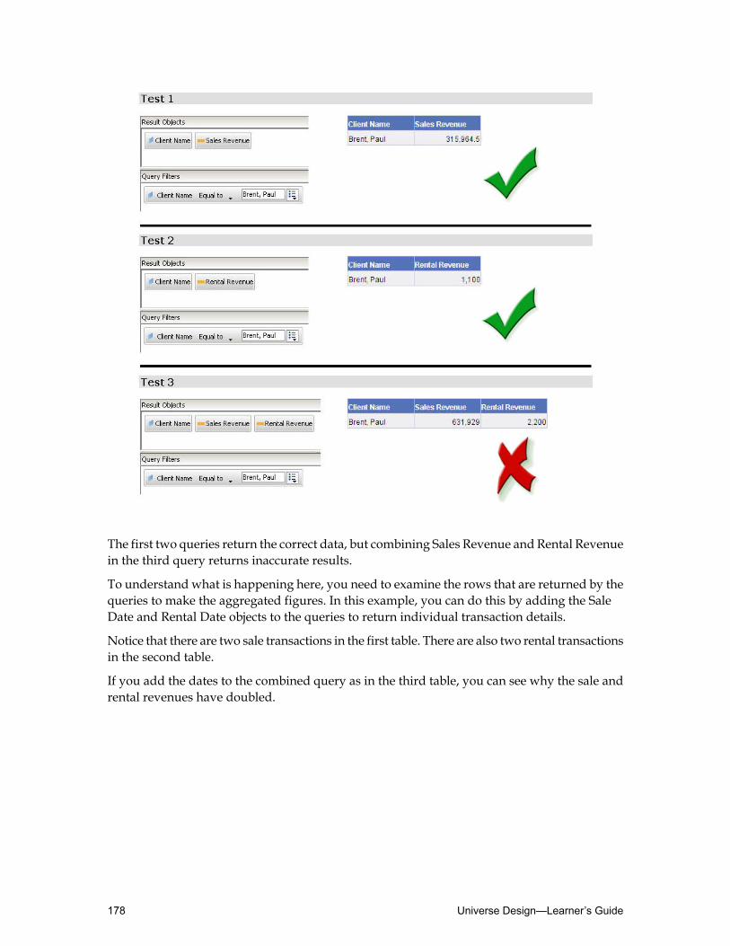
The first two queries return the correct data, but combining Sales Revenue and Rental Revenuein the third query returns inaccurate results.
To understand what is happening here, you need to examine the rows that are returned by thequeries to make the aggregated figures. In this example, you can do this by adding the SaleDate and Rental Date objects to the queries to return individual transaction details.
Notice that there are two sale transactions in the first table. There are also two rental transactionsin the second table.
If you add the dates to the combined query as in the third table, you can see why the sale andrental revenues have doubled.
Universe Design—Learner’s Guide178

The query returns every possible combination of sale rows with every possible combinationof rental rows. Hence, the sale transactions each appear twice as do the rental transactions, andas a result of this the aggregates have been multiplied by the number of related rows on thealternative "many" table.
Where you have a many-one-many relationship for tables in the FROM clause, the resultinglogical table produces something akin to a Cartesian product. Only then is aggregation applied.This is the reason for the chasm effect.
The problem with chasm traps is that, unless you look at the detail rows, there is nothing toalert you to the situation.
Resolving chasm traps
To resolve a chasm trap, you need to make two separate queries and then combine the results.Depending on the type of objects defined for the fact tables and the type of end-userenvironment, you can use the following methods to resolve a chasm trap:• Modify the SQL parameters for the universe so you can generate separate SQL queries for
each measure.
This method is not recommended as it only works with measures and results in certaininefficiencies in processing. It does not generate separate queries for dimension or detailobjects.
• Create a context for each fact table.
This solution works in all cases and does not result in inefficiencies.
Usingmultiple SQL statements for eachmeasure to resolve chasmtraps
If you have only measure objects defined for both fact tables, then you can use the UniverseParameters optionMultiple SQL statements for each measure. This forces the generation ofseparate SQL queries for each measure that is used in the query. It does not work for queriesthat do not contain measures.
179Resolving SQL Traps—Learner’s Guide
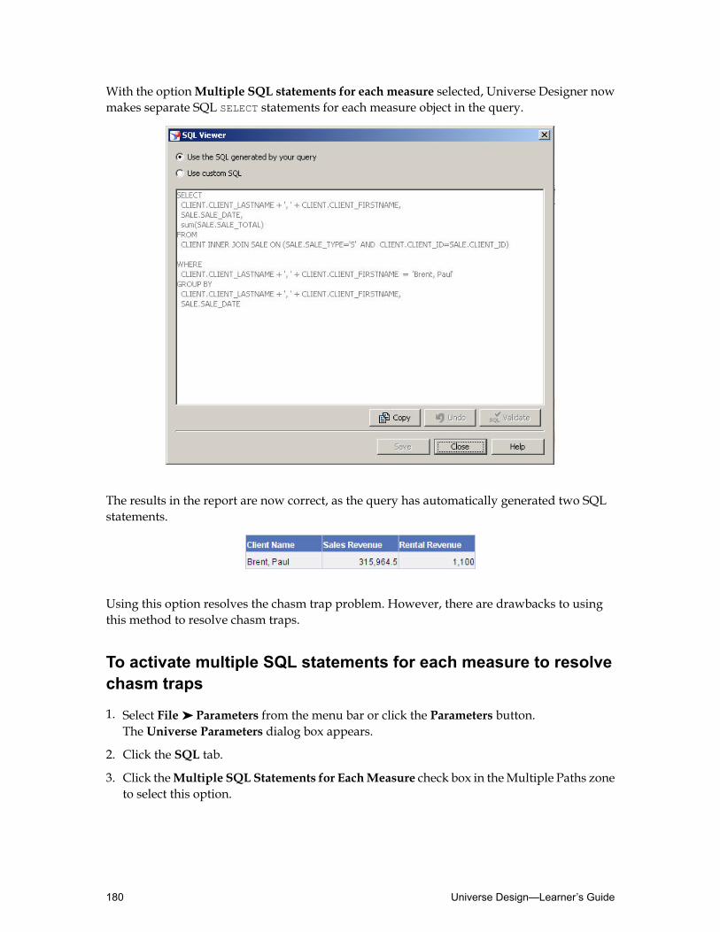
With the optionMultiple SQL statements for each measure selected, Universe Designer nowmakes separate SQL SELECT statements for each measure object in the query.
The results in the report are now correct, as the query has automatically generated two SQLstatements.
Using this option resolves the chasm trap problem. However, there are drawbacks to usingthis method to resolve chasm traps.
To activate multiple SQL statements for each measure to resolvechasm traps
1. Select File ➤ Parameters from the menu bar or click the Parameters button.The Universe Parameters dialog box appears.
2. Click the SQL tab.
3. Click theMultiple SQL Statements for EachMeasure check box in theMultiple Paths zoneto select this option.
Universe Design—Learner’s Guide180

4. ClickOK.
5. Save the universe.
6. In Web Intelligence Rich Client, create a new query using a dimension object, and twomeasure objects from the “many-to-one-to-many” table relationship.
7. Access the SQL that is generated in the SQL Viewer. Click View SQL.
This displays the separate SQL Statements.
8. Run the query.
The results in the report are now correct, as the query has automatically generated two SQLstatements.
Drawbacks to the multiple SQL statements for each measuremethod
Using the Multiple SQL statements for each measure option resolves the chasm trap problem.There are, however, two main drawbacks to using this method.
The results can be confusing
The SQL Parameter used specifies: “Multiple SQL statements for each measure”. One of thedrawbacks is that it does not run separate SELECT statements if the query contains onlydimension objects.
The report contains a single block with the results displayed as a Cartesian product.
181Resolving SQL Traps—Learner’s Guide

It is not that there is anything inaccurate about the dates, but the multiple occurrences areconfusing to users.
The query is inefficient
Another drawback is that any query including multiple measures infers a separate SELECTstatement for each measure irrespective of whether it is required or not.
To find a complete solution to chasm traps, you must use contexts.
Universe Design—Learner’s Guide182

Using contexts to resolve chasm traps
You can define a context for each table at the many end of the joins. In this example you coulddefine a context from Client to Sale and from Client to Rental.
When you run a query that includes objects from both contexts, this creates two SELECTstatements that are synchronized at run-time in BusinessObjects end-user query tools to preventthe creation of a Cartesian product.
Creating contexts always solves a chasm trap in a universe. When you have a"many-to-one-to-many" situation, always use a context.
To use contexts to resolve a chasm trap
1. Identify the potential chasm trap by analyzing themany-to-one-to-many join path relationsin the schema.
2. Select Tools ➤ Automated Detection ➤ Detect Contexts, or click theDetect Contextsbutton.
The Candidate Contexts dialog box appears.
3. Select a proposed context in the Candidate Contexts field and click Add to add it to theAccept Contexts field. ClickOK.
4. Repeat for other listed contexts.The new contexts are listed in the Contexts pane of the List Viewwindow.
5. Select File ➤ Parameters or click the Parameters button.
183Resolving SQL Traps—Learner’s Guide

The Universe Parameters dialog box appears.
6. Click the SQL tab.
7. Select theMultiple SQL for each Context check box to clear the option.
8. ClickOK.
When you run queries on the tables in the chasm trap, the query separates the SQL intowhat is compatible for separate SELECT statements.
Activity: Resolving chasm traps
Objective
• Detect contexts to resolve a chasm trap in the universe structure.
Instructions
1. Create a new universe called Chasm_xx, where "xx" stands for your initials.Use yourMotorsOLEDB_xx connection to connect to the Motors database.
2. Select File ➤ Parameters from the menu bar or click the Parameters button and select theSQL tab.
3. Clear theMultiple SQL statements for each measure option by clearing the check box.
4. Add the following tables:• CLIENT
• SALE
• RENTAL (as an alias of the SALE table)
5. Create the following joins and set the cardinality:
CardinalityJoin
1:NCLIENT.CLIENT_ID = SALE.CLIENT_ID
1:NCLIENT.CLIENT_ID = RENTAL.CLIENT_ID
1:1SALE.SALE_TYPE = 'S'
1:1RENTAL.SALE_TYPE = 'R'
6. Create two classes:
Universe Design—Learner’s Guide184

• Chasm Objects• Measures
7. Add the following objects with the following syntax:
Chasm Objects class
SELECT StatementObject Name
CLIENT.CLIENT_LASTNAME + ' , ' + CLIENT.CLIENT_FIRSTNAMEClient Name
SALE.SALE_DATESale Date
RENTAL.SALE_DATERental Date
Measures class
SELECT StatementObject Name
sum(SALE.SALE_TOTAL)Sales Revenue
sum(RENTAL.SALE_TOTAL)Rental Revenue
8. Perform an integrity check on:• Check Universe Structure• Parse Objects• Parse Joins
9. Select File ➤ Save As to save your universe locally.
10.InWeb Intelligence RichClient, create a newdocumentwith two “control” queries to displaythe correct sales and rental figures for Paul Brent in your Chasm universe.• In the first query, use the Sales Revenue, and Client Name objects.
Select the Client Name object, and click the Apply a Quick Filter button. From the Listof Values, select Brent, Paul.
• In the second query, use the Rental Revenue, and Client Name objects.
Select the Client Name object, and click the Apply a Quick Filter button. From the Listof Values, select Brent, Paul.
11.Click Run Queries and view the results in the report.• What is the sale amount?• What is the rental amount?
185Resolving SQL Traps—Learner’s Guide

12.In the same report add a new table by clicking the Edit Query button. Click Add Query,and create a newquery using theSales Revenue,Rental Revenue, andClientName objects.Select the Client Name object, and click the Apply a Quick Filter button. From the List ofValues, select Brent, Paul.
13.Click View SQL to check the SQL statement generated.
14.Click Run Queries and select the Insert a table in the current report option.• What is the sale amount in the new table?• What is the rental amount in the new table?• What happened to your figures?
15.InUniverseDesigner, edit the universe by clicking File➤ Parameters➤ SQL tab, and selecttheMultiple SQL statements for each measure option.
16.Save your universe locally.
17.In Web Intelligence Rich Client, create a new document using the Sales Revenue, RentalRevenue, and Client Name objects. Select the Client Name object, and click the Apply aQuick Filter button. From the List of Values, select Brent, Paul. Click View SQL to checkthe SQL statement generated.
Tip: You may need to refresh the universes list to get the latest version of your universe.Select Tools ➤ Universes and click Refresh.
• What is the sale amount?• What is the rental amount in the new table?• What happened to your figures?
18.Edit the query by clicking the Edit Query button on the toolbar.
19.Remove the Sales Revenue, and theRental Revenue objects. Add the SaleDate, andRentalDate objects. Click Run Query.• What happens to the SQL and to the results?
20.In Universe Designer, edit the universe by clicking File ➤ Parameters ➤ SQL tab and cleartheMultiple SQL statements for each measure option again (clear the check box).
21.Insert the following contexts:
JoinsContext
Universe Design—Learner’s Guide186
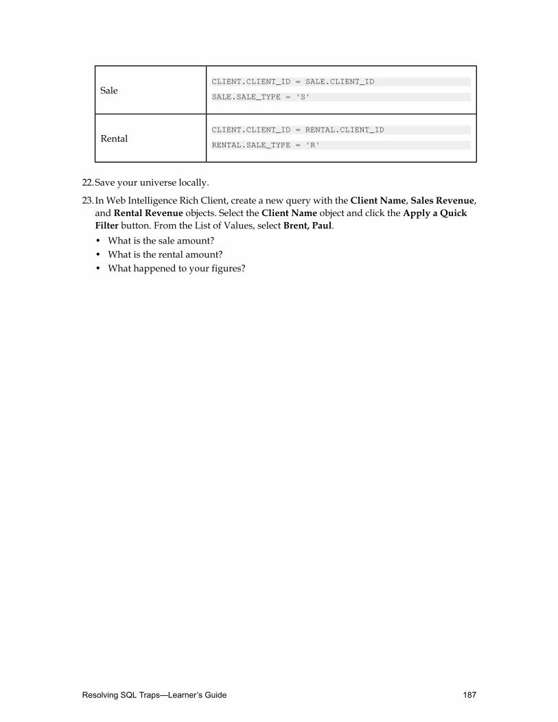
CLIENT.CLIENT_ID = SALE.CLIENT_ID
SALE.SALE_TYPE = 'S'Sale
CLIENT.CLIENT_ID = RENTAL.CLIENT_ID
RENTAL.SALE_TYPE = 'R'Rental
22.Save your universe locally.
23.In Web Intelligence Rich Client, create a new query with the Client Name, Sales Revenue,and Rental Revenue objects. Select the Client Name object and click the Apply a QuickFilter button. From the List of Values, select Brent, Paul.• What is the sale amount?• What is the rental amount?• What happened to your figures?
187Resolving SQL Traps—Learner’s Guide

Detecting and resolving fan trapsThis unit explains how fan traps can occur in the universe structure and how to resolve them.
After completing this unit, you will be able to:
• Define a fan trap• Detect fan traps in the universe structure• Resolve fan traps
Fan traps
Fan traps occur when there is a “one-to-many” join to a table that “fans out” into another“one-to-many” join to another table.
This is a common structure and does not normally result in a fan trap. You only get incorrectresults from the fan trap when the query includes a measure object on the middle table ('B') ofthe table path and an object (of any kind) from the subsequent table ('C'). The trap only occurswhere (due to the database design) a column in table B holds data values which are already asum of those values held at table C. The results are normally noticeably wrong.
When a query is run using objects Y and Z, the inferred SQL includes tables B and C whichhave a ‘one-to-many’ relationship. This results in a value for the Y object being multiplied bythe number of values of the Z object related to that Y object value. Like the chasm trap, theeffect is similar to a Cartesian product.
Like the chasm trap, the fan trap can be resolved by executing a separate SELECT statement forobject Y and object Z. The alternate solution is to avoid it in the first place.
You cannot automatically detect fan traps. You need to visually examine the direction of thecardinalities displayed in the table schema.
If you have two tables that are referenced by measure objects and are joined in a series of“many-to-one” joins, then you may have a potential fan trap.
Universe Design—Learner’s Guide188

The fan trap scenario
This section demonstrates a fan trap in the Motors schema, and proposes solutions to theproblem.
In the diagram below, the Client and Sale tables are joined by a “one-to-many-to-many”relationship, as are the Sale and Sale_Model tables.
The fan trap problem becomes apparent in a query that aggregates both an object based on theSale_Total column in the Sale table, and an object based on the Sale_Qty column in theSale_Model table.
189Resolving SQL Traps—Learner’s Guide

What happens in the fan trap
When you run the Test 1 query to report the Sales Revenue for a client, the measure is correctlyaggregated. This is a simple aggregate from one table in the fan trap structure. However, ifyou also wanted to know the number of vehicles the client has purchased, and you includedthe Number of Cars Sold object in the query, you get an inflated value returned for SalesRevenue.
To understand what is happening, you need to look at the rows that are returned. Since twodifferent Model ID numbers are involved in the Sale Quantity (Number of Cars Sold), thereare two rows returned.
As with chasm traps, a single SELECT statement joins each Model ID row with the same SalesRevenue row, which gives you the doubled figure.
There is nothing to alert you to the situation, unless you look at the detail rows.
Where you have a one-many-many relationship for tables in the FROM clause the resulting logicaltable produces something akin to a Cartesian product. Only then is aggregation applied. Thisis the reason for the fan effect.
Universe Design—Learner’s Guide190
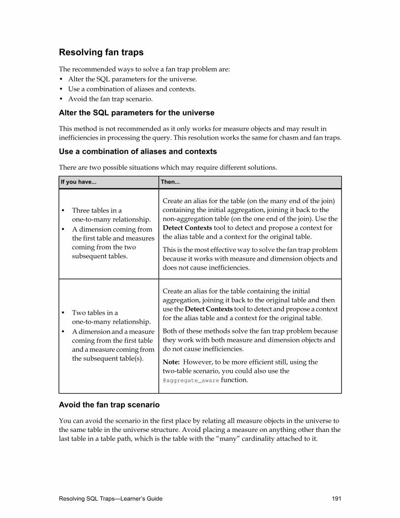
Resolving fan traps
The recommended ways to solve a fan trap problem are:• Alter the SQL parameters for the universe.• Use a combination of aliases and contexts.• Avoid the fan trap scenario.
Alter the SQL parameters for the universe
This method is not recommended as it only works for measure objects and may result ininefficiencies in processing the query. This resolution works the same for chasm and fan traps.
Use a combination of aliases and contexts
There are two possible situations which may require different solutions.
Then...If you have...
Create an alias for the table (on the many end of the join)containing the initial aggregation, joining it back to the• Three tables in a
one-to-many relationship. non-aggregation table (on the one end of the join). Use the• A dimension coming from
the first table andmeasuresDetect Contexts tool to detect and propose a context forthe alias table and a context for the original table.
coming from the twosubsequent tables.
This is themost effectiveway to solve the fan trap problembecause it works with measure and dimension objects anddoes not cause inefficiencies.
Create an alias for the table containing the initialaggregation, joining it back to the original table and then
• Two tables in aone-to-many relationship.
use theDetect Contexts tool to detect and propose a contextfor the alias table and a context for the original table.
• Adimension and ameasurecoming from the first tableand ameasure coming fromthe subsequent table(s).
Both of these methods solve the fan trap problem becausethey work with both measure and dimension objects anddo not cause inefficiencies.
Note: However, to be more efficient still, using thetwo-table scenario, you could also use the@aggregate_aware function.
Avoid the fan trap scenario
You can avoid the scenario in the first place by relating all measure objects in the universe tothe same table in the universe structure. Avoid placing a measure on anything other than thelast table in a table path, which is the table with the “many” cardinality attached to it.
191Resolving SQL Traps—Learner’s Guide

Using aliases and contexts to resolve fan traps
You create an alias table for the table producing the aggregation and then detect and implementcontexts to separate the query. This procedure is demonstrated in the diagram below:
In this scenario your schema would look similar to:
The SELECT clause of the Sales Revenue object needs to be edited, so that it refers to the aliastable rather than the original Sale table.
As with resolving a chasm trap problem, two contexts need to be created. In this example, acontext for Sale, and a context for Sale_Model need to be defined. This allows for the resultsto be merged into a single microcube to produce the correct results.
Moreover, if you make a query which includes a dimension object on the lower table in the"one-many-many" path, you do not get the fan trap, even when that dimension object contains
Universe Design—Learner’s Guide192

the same value for all rows related to the measure value. The fact that the measure anddimension objects are in separate contexts forces two separate SELECT statements, thus avoidingthe problem.
To use aliases and contexts to resolve a fan trap
1. Identify the potential fan trap by analyzing the "one-to-many-to-one-to-many" join pathrelations in the schema.
2. Create an alias for the table that is producing the multiplied aggregation.
3. Create a join between the new alias table, and the table that holds the dimension information.
4. Set cardinality.
5. Set contexts.
6. Change the SELECT clause of the measure object so that it refers to the alias table rather thanthe original table.
7. Create a query using a measure object from the alias table and another measure from thesubsequent table in the table path of the universe structure.
This results in two SELECT statements and the data is merged into a single microcube toproduce the correct results.
Scenario of a fan trap with two tables in a one-to-many relationship
The structure shownhere involves two tables instead of three. In this example, both a dimensionand measure object are from the same table, and another measure is from a table in aone-to-many relationship further along the universe structure.
To resolve this type of fan trap, you can:1. Create an alias of table A.
2. Create a join from the alias An to table A and set cardinalities.
3. Set contexts B and A.
4. Edit object Y so that it refers to columns in the alias An rather than table A.
193Resolving SQL Traps—Learner’s Guide

In the universe structure shown below, you have created an alias table of the Sale table andcreated a join between the alias and the original table. And two separate context have beendefined. This is to separate the dimension in Sale from the measure, which now refers toSale_Alias.
To solve a fan trap involving only two tables
1. Create an alias of the table that contains both dimension and measure values.
2. Create a join between the new alias table, and the original table.
3. Force the cardinality for this join to N:1.
4. Set contexts.
5. Change the SELECT clause of the measure object so that it refers to the new alias table ratherthan the original table.
6. Save the universe.
Universe Design—Learner’s Guide194

7. InWeb Intelligence Rich Client, test the solution using a dimension object from the originaltable, a measure object from the alias table, and a measure from the second table in theschema.
When you look at the SQL in the SQL Viewer, there are two SELECT statements.
Note: Aggregate awareness provides another solution to this problem.
Avoiding fan traps altogether
In certain situations, it is possible to avoid the fan trap completely, as shown in the diagrambelow.
To avoid the trap, the database column in table B to which the Y measure object relates mustrepresent a pre-aggregation of more detailed data in table C. If this is the case, you can changethe code of the Y measure object so that it refers to table C. Therefore, there is no longer a"one-to-many" relationship incurred.
This is the method used to avoid the fan trap in the Motors universe, when the Sales Revenueand Number of Cars Sold measure objects are included in the same query.
195Resolving SQL Traps—Learner’s Guide
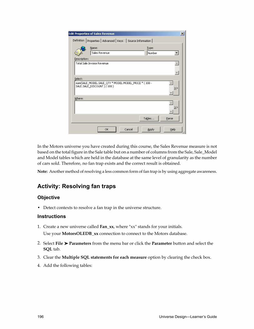
In the Motors universe you have created during this course, the Sales Revenue measure is notbased on the total figure in the Sale table but on a number of columns from the Sale, Sale_ModelandModel tables which are held in the database at the same level of granularity as the numberof cars sold. Therefore, no fan trap exists and the correct result is obtained.
Note: Anothermethod of resolving a less common form of fan trap is by using aggregate awareness.
Activity: Resolving fan traps
Objective
• Detect contexts to resolve a fan trap in the universe structure.
Instructions
1. Create a new universe called Fan_xx, where "xx" stands for your initials.Use yourMotorsOLEDB_xx connection to connect to the Motors database.
2. Select File ➤ Parameters from the menu bar or click the Parameter button and select theSQL tab.
3. Clear theMultiple SQL statements for each measure option by clearing the check box.
4. Add the following tables:
Universe Design—Learner’s Guide196

• CLIENT
• SALE
• SALE_MODEL
5. Create the following joins and set the cardinality:
CardinalityJoin
1:NCLIENT.CLIENT_ID = SALE.CLIENT_ID
1:NSALE.SALE_ID = SALE_MODEL.SALE_ID
1:1SALE.SALE_TYPE = 'S'
6. Create two classes:• Fan Objects• Measures
7. Add the following objects with the following syntax:
Fan Objects class
SELECT StatementObject Name
CLIENT.CLIENT_LASTNAME + ' , ' + CLIENT.CLIENT_FIRSTNAMEClient Name
SALE_MODEL.MODEL_IDModel ID
Measures class
SELECT StatementObject Name
sum(SALE.SALE_TOTAL)Sales Revenue
sum(SALE_MODEL.SALE_QTY)Number of Cars Sold
8. Perform an integrity check on:• Check Universe Structure• Parse Objects• Parse Joins
197Resolving SQL Traps—Learner’s Guide

9. Select File ➤ Save As to save your universe locally.
10.InWeb Intelligence RichClient, create a newdocument using theSales Revenue andClientName objects. Select the Client Name object and click the Apply a Quick Filter button.From the List of Values, select Randall, Sean.
11.Click Run Query and view the results in the report.• What is the sale amount?
12.Edit the query and add theNumber of Cars Sold object.• What is the sale amount now?• What is the total number of cars sold ?
13.In Universe Designer, edit the universe by clicking File➤ Parameters➤ SQL tab and selecttheMultiple SQL statements for each measure option.
14.Save your universe locally.
15.In Web Intelligence Rich Client, create a new document using the Sales Revenue,Numberof Cars Sold, and Client Name objects. Select the Client Name object and click the Applya Quick Filter button. From the List of Values, select Randall, Sean.
Tip: You may need to refresh the universes list to get the latest version of your universe.Select Tools ➤ Universes and click Refresh.
16.Click Run Query and view the results in the report.• What is the sale amount?• What is the total number of cars sold ?
17.Edit the query and add the Model ID object.• What is the total sale amount?• What is the total number of cars sold?• How many different models were purchased?• What happened to your figures?
Tip: To retrieve the sumvalue, highlight the relevantmeasure columnwithout highlightingthe header, and select the Insert Sum toolbar icon.
18.In Universe Designer, edit the universe by clicking File ➤ Parameters ➤ SQL tab and cleartheMultiple SQL statements for eachmeasure option by clearing the check box. Select theMultiple SQL statements for each context option if it is not already selected.
19.Add an alias to the SALE table (SALE2).
20.Create the following joins:
Universe Design—Learner’s Guide198

CardinalityJoin
1:NCLIENT.CLIENT_ID = SALE2.CLIENT_ID
1:1SALE2.SALE_TYPE = 'S'
Note: Force the cardinality on CLIENT.CLIENT_ID=SALE2.CLIENT_ID join to 1:N.
21.Use theDetect Contexts button to detect contexts.Be sure you have the following contexts. You may have to edit the context by removing oradding joins.
JoinsContext
CLIENT.CLIENT_ID = SALE.CLIENT_ID
SALE.SALE_ID = SALE_MODEL.SALE_ID
SALE.SALE_TYPE = 'S'
Sale Model
CLIENT.CLIENT_ID = SALE2.CLIENT_ID
SALE2.SALE_TYPE = 'S'Sale2
22.Modify the definition of the object that is performingmultiple aggregations so that it pointsto the alias table:
QualificationSELECTObject
Measuresum(SALE2.SALE_TOTAL)Sales Revenue
23.Save your universe locally.
24.In Web Intelligence Rich Client, create a new document using the Sales Revenue,Numberof Cars Sold, and Client Name objects. Select the Client Name object and click the Applya Quick Filter button. From the List of Values, select Randall, Sean.
25.Click Run Query and view the results in the report.• What is the total sale amount?• What is the total number of cars sold?• How many different models were purchased?• What happened to your figures?
199Resolving SQL Traps—Learner’s Guide

Quiz: Resolving SQL traps1. A chasm trap can occur when:
2. Describe two ways to resolve chasm traps.
3. Describe three ways to resolve fan traps.
Universe Design—Learner’s Guide200

Lesson summaryAfter completing this lesson, you are now able to:
• Understand SQL traps and universes• Resolve fan traps• Resolve chasm traps
201Resolving SQL Traps—Learner’s Guide

Universe Design—Learner’s Guide202
Lesson 8Applying Restrictions on Objects
Lesson introductionThis lesson helps you understand and use restrictions, which are conditions in SQL that setcriteria to limit the data returned by a query.
After completing this lesson, you will be able to:
• Restrict the data returned by objects
203Applying Restrictions on Objects—Learner’s Guide

Restricting the data returned by objectsA restriction is a condition in SQL that sets criteria to limit the data returned by a query.
You define restrictions on objects to limit the data available to users. Your reasons for limitinguser access to data depend on the data requirements of the target user. A user may not needaccess to all the values returned by an object. You might also want to restrict user access tocertain values for security reasons.
After completing this unit, you will be able to:
• Define data restrictions• Apply data restrictions to objects• Apply data restrictions using condition objects• Apply restrictions to tables• Apply data restrictions using the Tables button• Apply each type of restriction
Defining data restrictions
The WHERE clause in an SQL statement restricts the number of rows that are returned by thequery.
So far in your universe design work, the WHERE clauses have only been populated by the joinsyou made between the tables in the Structure pane.
The joins restrict the result sets, usually based on equality between tables and prevent Cartesianproducts.
You can also use the WHERE clause to further restrict the data that is returned in a query incircumstances where you may want to limit certain users to query on a subset of the data.
For example, the report below is an unrestricted block containing data for Clients from allCountries:
Universe Design—Learner’s Guide204

The WHERE clause for the query is created from the SQL inferred from the joins made in theStructure pane:WHERE (COUNTRY_REGION.COUNTRY_ID=REGION.COUNTRY_ID) AND (REGION.REGION_ID=CLIENT.REGION_ID) AND (SALE_MODEL.MODEL_ID=MODEL.MODEL_ID) AND (SALE.SALE_ID=SALE_MODEL.SALE_ID) AND (CLIENT.CLIENT_ID=SALE.CLIENT_ID) AND (SALE.SALE_TYPE='S') AND (SALE.SALE_DATE between FINANCE_PERIOD.FP_START and FINANCE_PERIOD.FP_END)
Compare this with the following report, which is a restricted block containing data only forclients from the United Kingdom:
The WHERE clause for the query now has an extra line at the bottom. This is the restriction addedby the designer that limits the return of data to UK Clients:WHERE (COUNTRY_REGION.COUNTRY_ID=REGION.COUNTRY_ID)AND (REGION.REGION_ID=CLIENT.REGION_ID) AND (SALE_MODEL.MODEL_ID=MODEL.MODEL_ID) AND (SALE.SALE_ID=SALE_MODEL.SALE_ID) AND (CLIENT.CLIENT_ID=SALE.CLIENT_ID) AND (SALE.SALE_TYPE='S') AND (SALE.SALE_DATE between FINANCE_PERIOD.FP_START and FINANCE_PERIOD.FP_END) AND (COUNTRY_REGION.COUNTRY_NAME = ‘United Kingdom’
Methods of restricting data in end-user modules
Within the design of a universe, you can either:• Force restrictions, which the end user cannot override: object, table, conditional SELECT, and
additional joins
• Provide optional restrictions, which the end user can choose to apply: condition objects
Remember that users can apply conditions themselves in their Business Objects querying tool.Therefore, avoid creating optional restrictions that are of a simple nature, as the end user shouldbe capable of creating such conditions for themselves on a query-by-query basis.
There are often problems associated with inferred restrictions. You are therefore advised onlyto force restrictions where they are absolutely necessary.
To ensure that a restriction is always inferred when a particular object is used in an end-userquery, place the restriction in theWhere field of theDefinition tab in the Edit Properties dialogbox related to the object. You can do this when you create the object or you can add it later.
205Applying Restrictions on Objects—Learner’s Guide

To apply a restriction to an object
1. Open the Edit Properties dialog box for the object and select theDefinition tab.
2. Enter the restriction directly in theWhere field, or via the Edit Where Clause dialog box byselecting the >> button.
3. ClickOK.
When you have created or edited your object to include a restriction, you should test it byrunning a new query using a BusinessObjects end-user query tool. Always view the inferredSQL to check whether the SELECT statement includes the restriction in the WHERE clause andhas the desired effect. Remember to save your universe before doing this.
The inferred SQL displays the restriction. The last line of the WHERE clause is taken from theobject restriction.
Drawbacks to applying restrictions to objects
Only create restrictions against objects when it is absolutely necessary.
For example, consider the situation where users of Motors need to make queries of only thosecars that can be rented. In theModel table in the underlyingMotors database, the distinguishingfactor between cars that can be rented and those that are stocked for sale, is that theModel_Dayrent column contains data for rental cars and is null for sale-only cars. To create anobject to list cars for rental, the object would have to include the restriction:MODEL.MODEL_DAYRENT IS NOT NULL
If it is not necessary, do not create the restriction.
To see why, consider the implications of creating a UK Clients object as illustrated:
Universe Design—Learner’s Guide206

The drawbacks are as follows:• You would get a confusing proliferation of objects for end users because you would then
need a French Clients object, a German Clients object, and so on.
• As these objectswould all represent alternate restrictions, youwould not be able to constructa logical default hierarchy, which end users make use of when drilling down.
• Although the UKClients example is fairly clear, in many cases the restriction is not obviousto the user simply from the name of the object: the details of the WHERE clause are not shownin the end-user interface.
• If two ormore similarly restricted objects are included in the same query, the conflict betweenthe WHERE clauses causes no data to be returned.
Consider the situation if a user wanted data for UKClients andUS Clients. Youmight thinkthat including both the UK Clients and US Clients objects would meet that need. However,the inferred SQL for the query would include the following two lines:
AND (COUNTRY_REGION.COUNTRY_NAME = 'United Kingdom') AND (COUNTRY_REGION.COUNTRY_NAME = 'USA')
As no country satisfies both these conditions, no data is returned.
An alternative to applying restrictions to objects
There is an alternative to applying restrictions to objects without using WHERE clauses. You stillhave multiple objects, but you avoid the conflicts that affect the return of data in queries.
Thismethod involves using a conditional SELECT clause for the object instead of a WHERE clause.
For example, if you want to force users to select financial results by year, you could create aseries of Sales Revenue objects (one for each year). Each object would be edited, starting fromthe standard sum aggregate used in the basic Sales Revenue SELECT statement:
You would apply the condition for each year using the database function that applies IF THENELSE logic.
For Sales Revenue 2003, the SELECT statement looks like this:
Note: The Else value 0 is optional.
207Applying Restrictions on Objects—Learner’s Guide
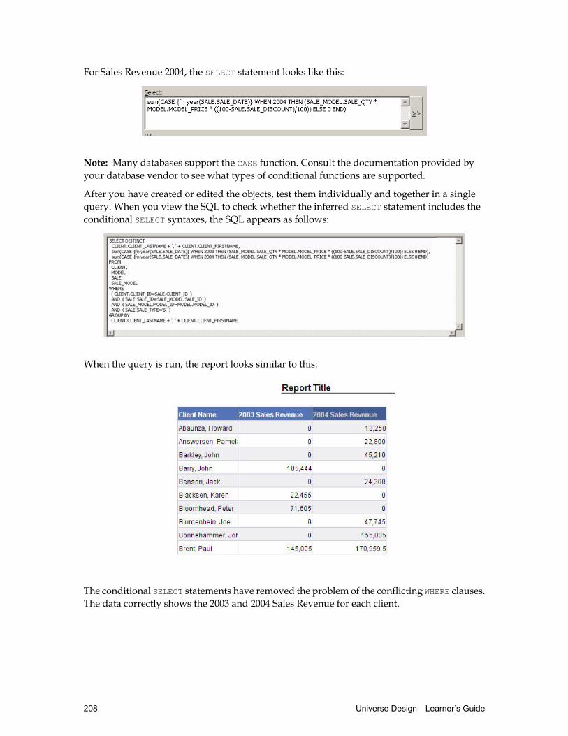
For Sales Revenue 2004, the SELECT statement looks like this:
Note: Many databases support the CASE function. Consult the documentation provided byyour database vendor to see what types of conditional functions are supported.
After you have created or edited the objects, test them individually and together in a singlequery. When you view the SQL to check whether the inferred SELECT statement includes theconditional SELECT syntaxes, the SQL appears as follows:
When the query is run, the report looks similar to this:
The conditional SELECT statements have removed the problem of the conflicting WHERE clauses.The data correctly shows the 2003 and 2004 Sales Revenue for each client.
Universe Design—Learner’s Guide208

Restrictions using condition objects
A condition object, or predefined query filter, is a preset restriction created inUniverseDesignerthat a user can choose whether or not to apply to a query.
When users create queries they can create their own query filters to limit the data returned bythe query. They can also use the predefined query filters that the universe designer may havebuilt into the universe to make it easier for them to restrict the data.
For example, if the designer has created condition objects for French Clients and UK Clientsin Universe Designer, the Predefined Conditions tab would contain these condition objects:
InWeb Intelligence Rich Client, the predefined query filter built into the universe can be viewedin the Report ManagerData tab, identified as predefined query filters.
When you have created a condition object in Universe Designer, test it inWeb Intelligence RichClient by making a query that uses the filter. View the SQL to check that the inferred SELECT
statement includes the restriction in the WHERE clause and has the desired effect.
The advantages of using condition objects
• Useful for complex or frequently used conditions.
• Gives users the choice of applying the condition.
• No need for multiple objects.
• Condition objects do not change the user view of the dimension objects in the Classes andObjects tab in the Web Intelligence Rich Client.
To create a condition object
1. In Universe Designer, select the Filter option button at the bottom of the Universe pane.
The Universe pane changes to show the Condition Object View.
Note: Objects are not shown in the Condition Object View, but classes are. You add acondition object to a particular class. Also, be aware that deleting a class in the ConditionObject View deletes that class from the whole universe, not just from this view.
2. Click the class in which you want to place the condition object.
3. There are two ways you can insert a condition:• Select the Insert Condition button on the Editing toolbar.
• Right-click the class and choose Condition from the drop-down menu.
This opens the Edit Properties dialog box for condition objects.
209Applying Restrictions on Objects—Learner’s Guide

4. In the Name field, enter a name for the condition object.
5. In the Description field, enter a help message for users describing the condition and anyeffect it has on queries they make.
6. Enter the condition directly in the Where field or via the Edit Where Clause dialog box byselecting the >> button.
7. ClickOK.
8. Save the universe.The newpredefined condition object built into the universe can be viewed inWeb IntelligenceRich Client in the Report PanelData tab.
Applying restrictions using the tables button
If a table in your database has a flag that is used to switch between two or more domains, youcan use this to apply restrictions at the table level.
For example, the Sale table in the Motors database has a column called Sale_Type, which isused to distinguish between sales transactions and rentals transactions. The flag is set to S forsales or R for rentals.
If you do not apply any restriction to this table, users running queries for sales (with appropriateobjects) get a resulting report that includes data on rentals aswell as sales. Therefore, the resultsare wrong.
You can apply a restriction to this table using a self-restricting join.
The self-restricting join appears as a stub join in the Structure pane:
The expression in the Edit Join dialog box is set as follows:
With this restriction in place, the data returned is restricted to sales data, no matter where thetable is used in the inferred SQL.
For example, if the Sale table appears only in the FROM clause of the SQL, the restriction is stillapplied in the WHERE clause.
Universe Design—Learner’s Guide210

This is the main advantage of applying restrictions at the table level.
A lookup table in a database can be used to provide a description for more than one dimensionfrom a database.
For example, in the Motors database, the Country table contains a single list of countries, butthese include the country fromwhich clients come, the countrywhere a car showroom is located,and the country where a car maker is located.
As a designer, you can create objects from the Country table for use in the Client class (for theClient Country), in the Showroom class (for the Showroom Country), and in the Car class (forthe car Maker Country).
If a user ran a query to answer the question: “Which countries do our showrooms exist in?”,youmight think that a simple query using only the ShowroomCountry object in the Showroomclasswould provide the answer. However, in the current universe, such a querywould actuallyinfer SQL that returns all countries held in the Showroom_Country table.SELECTSHOWROOM_COUNTRY.COUNTRY_NAME
FROMSHOWROOM_COUNTRY
To solve this problem, the ShowroomCountry object in the Showroom class must be restrictedso that it returns only country data relating to showrooms.
This is done by specifying that whenever the Showroom Country object is used in a query, theShowroom table must also be inferred in the FROM clause of the SELECT statement. Providingthat the Showroom_Country table is joined to the Showroom table (by intervening tables) using
211Applying Restrictions on Objects—Learner’s Guide

only equi-joins, the object is then guaranteed to only return countries in which showroomsexist.
To restrict data by adding tables to the object definition
1. Double-click the object you want to restrict.
The Edit Properties dialog box for the selected object displays.
2. Click the Tables button.
The Tables dialog box appears.
3. Scroll down the list of tables until you can see the table that is already highlighted.
4. Hold down the Ctrl key and click an additional table to force joins between the selectedtables.
5. ClickOK to close the Tables dialog box.
6. Click Apply in the Edit Properties dialog box.
7. ClickOK.
Applying each type of restriction
Apply restrictions to objects when you need to force a restriction on users. Be aware of thedrawbacks of multiple objects and conflicting restrictions. Use conditional SELECT statementsinstead.
Use condition objects when you want to assist users by providing optional filters, and when itis important to avoid multiple objects and changes to the Classes and Objects view.
Use self-restricting joins to apply restrictions to tables when you want the restriction to apply,irrespective of where the table is used in the SQL. This method is ideal when a table uses a flagto switch between two or more domains.
Use additional joins when a lookup table serves more than one purpose in the universe. Thismethod ensures that the user gets the correct answer to the question behind the query.
Activity: Applying restrictions
Objective
• Apply enforced restrictions to objects and tables and create optional restrictions usingcondition objects.
Instructions
The sales staff of Prestige Motors needs to drill from Day Rental Range through Model DayRental Charge to Model for Rental to deal with queries from potential customers.1. Create aModel for Rental dimension object in the Day Rental Charges subclass.
Universe Design—Learner’s Guide212

This object has the same SELECT properties as theModel object.
2. Add a WHERE restriction to theModel for Rental object so that onlymodels available for rentare returned. The restriction is:MODEL.MODEL_DAYRENT IS NOT NULL
3. Create a US Clients dimension object in the Client class below the Client Name object withthe settings:• Type = Character• Description = Returns only data for clients in the USA
• Select syntax:CLIENT.CLIENT_LASTNAME + ', ' + CLIENT.CLIENT_FIRSTNAME
• Where syntax:COUNTRY_REGION.COUNTRY_NAME = 'USA'
4. Create another object in the Client class for UK Clients.
5. Save your universe locally and then test the two newClient objects inWeb Intelligence RichClient:• Build a query containing UK Clients, US Clients, and Sales Revenue objects
The query returns no data because of the conflict of restrictions.
6. In Universe Designer, create a new subclass below the Sales class called Annual Revenue.Populate it with separate Sales Revenue measure objects for the calendar years 2003 and2004 as indicated below. Use the CASE function.• 2003 Sales Revenue• 2004 Sales Revenue
7. In theAnnual Revenue subclass create two separate Sales Revenuemeasure objects relatedto financial years FY03-04 and FY04-05 as indicated below. Use the CASE function.• Sales Revenue for FY03-04• Sales Revenue for FY04-05
8. Save your universe locally, then test the two new calendar year Sales Revenue objects inWeb Intelligence Rich Client:• Build a query containing Showroom, 2003 Sales Revenue, and 2004 Sales Revenue
objects.• Replace the 2003 Sales Revenue and 2004 Sales Revenue objectswith theSales Revenue
for FY03-04 and Sales Revenue for FY04-05 objects.
9. Remove the US and UK objects in the Client class that you just created, and create thefollowing condition objects instead:• A condition object for US Clients.• A condition object for European Clients.• A condition object for Other Clients.
213Applying Restrictions on Objects—Learner’s Guide

10.Save your universe locally and test each restriction by building a query inWeb IntelligenceRich Client.
11.Run a query using Showroom Country to see the list of countries that have showrooms.
12.In Universe Designer, edit the properties of the Showroom Country object by adding theShowroom table to the list of tables associatedwith the object. Use theTables button in EditProperties ➤ Definition of the object.
13.Save your universe locally.
14.In Web Intelligence Rich Client, run the above query again and compare the results.
15.In Universe Designer, ensure that the Client Country object only returns the countries inwhich clients exist, whichever query is run. Do this by adding the Client table to the list oftables associated with the object.
16.Edit the Maker Country object in the same way to ensure that it only returns the countriesin which car makers exist.
17.Edit the Franchise object so that it automatically infers the FRANCHISE context instead ofprompting the user to choose among the SALES, RENTALS, and FRANCHISE contexts.This allows end users to report on the franchises and their location regardless of sales orrentals information.Use the Tables button to highlight the MAKER and FRANCHISE tables.
18.Check the integrity of your universe.
19.Save your universe locally.
Universe Design—Learner’s Guide214

Quiz: Applying restrictions on objects1. What is a restriction?
2. Explain two drawbacks of using restrictions at the object level.
3. When should you use self-restricting joins?
215Applying Restrictions on Objects—Learner’s Guide

Lesson summaryAfter completing this lesson, you are now able to:
• Restrict the data returned by objects
Universe Design—Learner’s Guide216

Lesson 9Using @functions with Objects
Lesson introductionThis lesson helps you use the @functions to provide more flexible methods for specifying theSQL for an object.
After completing this lesson, you will be able to:
• Use @functions
217Using @functions with Objects—Learner’s Guide

Using @functionsThe @functions are located in the Functions panel of the Edit Select Statement and in the EditWhere Clause dialog boxes for objects.
After completing this unit, you will be able to:
• Define @functions• Use the @prompt function• Use the @select function• Use the @where function• Describe the @aggregate_aware function
Defining @functions
In the Edit Properties dialog box of an object, if you look in the Functions panel of either theEdit Select Statement dialog box or the Edit Where Clause dialog box, you find a list of@functions.
The most commonly used @functions are:• @prompt(,,,,,,)
• @select()
• @where()
• @aggregate_aware(,)
These functions can be applied in the Select and/or Where fields of objects.
Can be used in...@function
Both SELECT and WHERE clauses.@prompt
Only to be used in SELECT clauses.@select
Only to be used in WHERE clauses.@where
Only to be used in SELECT clauses.@aggregate_aware
The @functions are used to provide flexible methods of specifying SQL.
@prompt
The @prompt function is used by the designer to force the end user to enter a value for arestriction when a query is run which includes the object in which the @prompt is specified.
Universe Design—Learner’s Guide218

This is done by placing a restriction based on the @prompt in the Where field of the EditProperties dialog box of an object. When the user runs a query including that object, a promptdialog box appears requesting a value to be entered.
It can be useful when you want to force a restriction in the inferred SQL but do not want topreset the value of the condition. For example:
In the example, the object Model for Rental is to be used by a salesman to list the models thatcan be rented. However, different models are rented from different showrooms. Therefore,youwould want to restrict the returned list to cars rented from a single showroom. If you hardcoded the restriction, you would need a separate object for each showroom in the universe.Using the @prompt function, you need only one.
@prompt syntax
The @prompt syntax consists of seven parameters, separated by commas:• Prompt.• Data type (A, N, or D).• LOV pointer or hard-coded list.• Mono or multi.• Free, constrained, or primary_key.• Persistent or not persistent.• 'Default value':'key value'.
Note: The first two parameters are mandatory, and the remaining parameters are optional.The first three parameters must be inside single quotes.
219Using @functions with Objects—Learner’s Guide

Prompt
This is the text, or question, that appears in the prompt dialog box when the query is run. Thetext must be enclosed in single quotes.
Data type
Data type refers to a character to specify the type of data that is returned:
'A' for alphanumeric
'N' for numeric
'D' for date
The specified character must be enclosed in single quotes.
List of values (optional)
There are two methods of specifying a list of values:• A hard-coded list:
Each value is separately enclosed in single quotes and separated by a comma and thewholelist is enclosed in curly brackets. For example:{'Australia', 'France', 'Japan', 'United Kingdom', 'USA'}
• A pointer to a list of values from an existing object:
This can be invoked by double-clicking the object whose list of values you want to use intheClasses andObjects selection list. This gives the class name and the object name, separatedby a back-slash. It must be enclosed in single quotes. For example:'Client\Country'
Mono or multi (optional)
• Mono: Allows the user to select or enter a single value from the list of values.
• Multi: Allows the user to select or enter multiple values from the list of values.
Free, constrained, or primary_key (optional)
• Free: Users can enter a value of their own, or pick one from the list of values.
• Constrained: Users can only choose a value from the list of values.
• Primary_key: The user enters a value or selects from the list of values. If the primary keyparameter is present, the entered or displayed value is not used to generate the query. Theassociated key value from the index awareness column is used.
Universe Design—Learner’s Guide220

Persistent or not persistent (optional)
• Persistent: When refreshing a document, the last values used in the prompt are displayedby default.
• Not persistent: When refreshing a document, no values previously used/selected in theprompt are displayed in the prompt by default.
'Default value':'key value' (optional)
The default values parameter is used to define default values presented to the user.
You can define multiple default values. The syntax for each default value is: 'value':'key'. Thecolon (:) is the separator between the value and the key.
When refreshing a document these values are displayed by default but if the persistent optionis set, then the last values used in the prompt are used instead of the default values.
If you specify the primary key parameter in the prompt definition, then you must provide thekey value(s).
@prompt syntax examples
Examples of the different @prompt syntaxes that can be used are listed below:• @prompt syntax, using the first five parameters:
SHOWROOM.SHOWROOM_NAME = @prompt('Enter Showroom Name','A', 'Showroom\Showroom',mono,constrained)
Note: Make sure the syntax parses OK. When inserting the @prompt function in the Selectfield, it automatically inserts seven commas. You may need to remove the remaining twocommas in the @prompt syntax.
• @prompt syntax, using mono, constrained, persistent:SHOWROOM.SHOWROOM_NAME =@prompt('Enter Showroom Name','A', 'Showroom\Showroom',mono,constrained,persistent)
The above example uses the "persistent" option.When refreshing a document, the last valuesused in the prompt are displayed by default.
• @prompt syntax, using mono, constrained, not_persistent:SHOWROOM.SHOWROOM_NAME =@prompt('Enter Showroom Name','A', 'Showroom\Showroom',mono,constrained,not_persistent)
The above example uses the "not_persistent" option.When refreshing a document, no valuesused are displayed by default in the prompt.
• @prompt syntax, using multi, constrained, persistent:SHOWROOM.SHOWROOM_NAME IN@prompt('Enter Showroom Name','A', 'Showroom\Showroom',multi,constrained,persistent)
The above example uses the "persistent" option.When refreshing a document, the last valuesused in the prompt are displayed by default. Combining this with the "multi" option allowsthe user to select or enter multiple values from the list of values.
221Using @functions with Objects—Learner’s Guide

• @prompt syntax, using multi, constrained, not_persistent:SHOWROOM.SHOWROOM_NAME IN@prompt('Enter Showroom Name','A', 'Showroom\Showroom',multi,constrained,not_persistent)
The above example uses the "not_persistent" option.When refreshing a document, no valuespreviously used/selected in the prompt are displayed by default in the prompt. Combiningthis with the "multi" option allows the user to select or enter multiple values from the listof values.
• @prompt syntax, using mono, and primary_key:SHOWROOM.SHOWROOM_NAME =@prompt('Enter Showroom Name','A', 'Showroom\Showroom',mono,primary_key)
The above example uses the "primary_key" option.When prompted the user enters or selectsone value from the list of values, as the "mono" option is used. If the primary_key parameteris present, the entered or displayed value is not used to generate the query. The associatedkey value from the index awareness column is used instead. The function returns an integervalue (index). The primary_key option in the @prompt function needs to be assigned to aninteger or numeric database field, in this example, SHOWROOM.SHOWROOM_ID. This can be doneusing index awareness.
If the user selects "Prestige Sports Cars" from the list of values, the SHOWROOM.SHOWROOM_IDvalue is used to generate the query:SELECT sum(SALE_MODEL.SALE_QTY * MODEL.MODEL_PRICE *(100 - SALE.SALE_DISCOUNT )/100)FROMMODEL INNER JOIN SALE_MODEL ON (SALE_MODEL.MODEL_ID=MODEL.MODEL_ID)INNER JOIN SALE ON (SALE.SALE_ID=SALE_MODEL.SALE_ID)INNER JOIN SHOWROOM ON (SALE.SHOWROOM_ID=SHOWROOM.SHOWROOM_ID)WHERE(SALE.SALE_TYPE='S')AND (SHOWROOM.SHOWROOM_ID = 2 )
• @prompt syntax, using multi, and primary_key:SHOWROOM.SHOWROOM_NAME IN@prompt('Enter Showroom Name','A', 'Showroom\Showroom',multi,primary_key)
The above example uses the "primary_key" option.When prompted the user enters or selectsone or more values from the list of values, as the "multi" option is used. If the primary_keyparameter is present, the entered or displayed value is not used to generate the query. Theassociated key value from the index awareness column is used instead. The function returnsan integer value (index). The primary_key option in the @prompt function needs to be assignedto an integer or numeric database field, in this example, SHOWROOM.SHOWROOM_ID. This canbe done using index awareness.
If the user selects all showrooms from the list of values, the SHOWROOM.SHOWROOM_ID valueis used to generate the query:SELECT sum(SALE_MODEL.SALE_QTY * MODEL.MODEL_PRICE *(100 - SALE.SALE_DISCOUNT )/100)FROMMODEL INNER JOIN SALE_MODEL ON (SALE_MODEL.MODEL_ID=MODEL.MODEL_ID)INNER JOIN SALE ON (SALE.SALE_ID=SALE_MODEL.SALE_ID)INNER JOIN SHOWROOM ON (SALE.SHOWROOM_ID=SHOWROOM.SHOWROOM_ID)WHERE
Universe Design—Learner’s Guide222
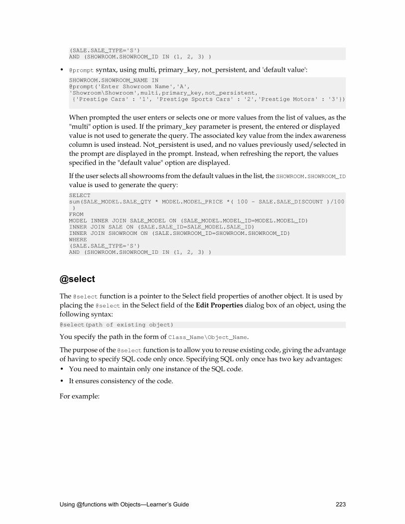
(SALE.SALE_TYPE='S')AND (SHOWROOM.SHOWROOM_ID IN (1, 2, 3) )
• @prompt syntax, using multi, primary_key, not_persistent, and 'default value':SHOWROOM.SHOWROOM_NAME IN@prompt('Enter Showroom Name','A', 'Showroom\Showroom',multi,primary_key,not_persistent, {'Prestige Cars' : '1', 'Prestige Sports Cars' : '2','Prestige Motors' : '3'})
When prompted the user enters or selects one or more values from the list of values, as the"multi" option is used. If the primary_key parameter is present, the entered or displayedvalue is not used to generate the query. The associated key value from the index awarenesscolumn is used instead. Not_persistent is used, and no values previously used/selected inthe prompt are displayed in the prompt. Instead, when refreshing the report, the valuesspecified in the "default value" option are displayed.
If the user selects all showrooms from the default values in the list, the SHOWROOM.SHOWROOM_IDvalue is used to generate the query:SELECT sum(SALE_MODEL.SALE_QTY * MODEL.MODEL_PRICE *( 100 - SALE.SALE_DISCOUNT )/100 )FROMMODEL INNER JOIN SALE_MODEL ON (SALE_MODEL.MODEL_ID=MODEL.MODEL_ID)INNER JOIN SALE ON (SALE.SALE_ID=SALE_MODEL.SALE_ID)INNER JOIN SHOWROOM ON (SALE.SHOWROOM_ID=SHOWROOM.SHOWROOM_ID)WHERE(SALE.SALE_TYPE='S')AND (SHOWROOM.SHOWROOM_ID IN (1, 2, 3) )
@select
The @select function is a pointer to the Select field properties of another object. It is used byplacing the @select in the Select field of the Edit Properties dialog box of an object, using thefollowing syntax:@select(path of existing object)
You specify the path in the form of Class_Name\Object_Name.
The purpose of the @select function is to allow you to reuse existing code, giving the advantageof having to specify SQL code only once. Specifying SQL only once has two key advantages:• You need to maintain only one instance of the SQL code.
• It ensures consistency of the code.
For example:
223Using @functions with Objects—Learner’s Guide

This example shows how the @selectworks. The code in the SELECT properties of the Modelobject is:MODEL.MODEL_NAME+' '+ MODEL.MODEL_TRIM+' '+MODEL.MODEL_ENGINE
If you wish to create a new object called Model for Rental with the same code, rather thancreating the same code twice, you can refer to the originalModel object via the @select function:@select(Car\Model)
Universe Design—Learner’s Guide224

The benefit is that a dynamic link is created between the objects. When changes occur in theSELECT statement of the original object, the changes are reflected in the SELECT statement ofany other objects that refer to it via the @select function. Therefore, when you change the code,you only change it once in the original object.
@where
The @where function is a pointer to the WHERE properties of another object.
It is used by placing the @where in theWhere field of the Edit Properties dialog box of an object,using the following syntax:@where(path of existing object)
For example:
225Using @functions with Objects—Learner’s Guide

This example shows how the @whereworks. The code in the WHERE syntax of the Model forRental object is:MODEL.MODEL_DAYRENT IS NOT NULL AND SHOWROOM.SHOWROOM_NAME = @prompt('Enter Showroom Name','A','Showroom\Showroom',mono, constrained)
If you wish to create a new object called Showroom Rental Model that has to contain the sameWHERE syntax, rather than creating the same code twice, you can refer to the original Model forRental object via the @where function:@where(Day Rental Charges\Model for Rental)
Universe Design—Learner’s Guide226

The benefit is that a dynamic link is created between the objects. When changes occur in theWHERE clause of the original object, the changes are reflected in the WHERE clause of any otherobjects that refer to it via the @where function. Therefore, when you need to change the syntax,you only change it once in the original object.
Note: You can use the @where function in a condition object to point to an object, but not theother way around.
As with @select, its purpose is to allow you to reuse existing code, and it has the sameadvantages:• You need to maintain only one instance of the SQL code.
• It ensures consistency of the code.
There are further benefits for using the @where function. If there are a number of objects and/orcondition objects that require the same restrictions to be placed upon them, you could use aWHERE restriction object strategy to make the most efficient use of that restriction’s code.
227Using @functions with Objects—Learner’s Guide

The idea behind the strategy is that you create a new and separate object for every restrictionrequired, in a separate class to the “normal” object classes. Then, within the original objects,whenever a restriction is required, you point to the appropriate WHERE restriction object usingthe @where function.
In the previous example, you can see that two WHERE clause restriction objects have been createdthat contain only a name and WHERE clause restriction, as follows:
Rental model
MODEL.MODEL_DAYRENT IS NOT NULL
Showroom choice
SHOWROOM.SHOWROOM_NAME = @prompt ('Enter Showroom Name','A','Showroom\Showroom',mono, constrained)
Note that each of these restriction objects do not have SELECT properties specified.
The @where pointer can now be used to specify the restrictions required for the object calledModel for Rental without the need to double up on the WHERE syntax.
Also, by specifying each restriction in a separate WHERE clause restriction object, the strategyhas enabled you to build up the multiple restrictions on the object one step at a time. This isparticularly useful when creating complex restrictions on an object.
Moreover, the individual restrictions can be used for other objects and condition objects. In theexample above, theWhere clause restriction object called ShowroomChoice has also been usedfor the Showroom condition object.
For this strategy to work, you need to be able to hide the class containing all the WHERE clauserestriction objects from end users.
The Where clause restriction object strategy has a number of advantages:• Maintenance is easy because only a single instance of each restriction is required.
• The restrictions are easy to find. They are all under a single class. Restrictions can be mixedand matched without the need for repetition.
To hide the class containing all theWhere clause restriction objectsfrom end users
1. Click the class or object you want to hide.
2. There are different ways to hide classes and objects:• Select the Show or Hide Item button on the Editmenu.• Right-click the object or class and selectHide Item(s) from the drop-down menu.• Use Ctrl+Shift+H.
Hidden classes and objects appear in italics in the Universe Designer Universe pane.They are not shown at all in Business Objects end-user querying tools.
Universe Design—Learner’s Guide228
@aggregate_aware
Somedatabases contain summary tables. These tables are created by theDatabaseAdministrator(DBA) and contain figures such as revenue aggregated to a high level (year, for example) ratherthan to the fact/event level. The summary tables are usually populated and updated regularlyby an automated program that runs SQL against the fact or event data at transaction level.
This means that there are two methods that you can use to return aggregated data:• Run a SELECT statement for the fact or event data.
• Run a SELECT statement for the summary data.
Where possible, it is best to choose the latter method as the statement processes quicker.
In Universe Designer, you can use a function called @aggregate_aware in the SELECT statementfor an object, so that both methods are referenced. This function directs a query to run againstaggregate tables whenever possible. If the data in the aggregate table is not calculated at thelevel of granularity required to run the query, the object directs the query to run against thetables containing the non-aggregated data.
A universe that has one or more objects with alternate definitions based on aggregate tables issaid to be aggregate aware. These definitions correspond to levels of aggregation. For example,an object called Profit can be aggregated by month, by quarter, or by year.
The reliability and usefulness of aggregate awareness in a universe depends on the accuracyof the aggregate tables. They must be refreshed at the same time as all fact tables.
When you apply the @aggregate_aware function, be aware of the available levels, and be clearabout the descending order of aggregation.
Each aggregation level SELECT statement is separated by a comma, and the entire expressionis enclosed in brackets. The final SELECT statement must be valid for all queries.@aggregate_aware(<SELECT statement for highest agg level>,<SELECT statement for second highest agg level>, .. <SELECT statement for second lowest agg level>, <original SELECT statement for basic agg calculation>)
Applying aggregate awareness to objects in a BusinessObjects universe involves a four-stepprocedure:
Step 1: Insert one or more summary tables in the universe structure. Set joins and cardinality.
Step 2: Set the contexts.
Step 3: Redefine the objects using @aggregate_aware.
Step 4: Define incompatible objects using Aggregate Navigation.
Note: For more information, refer to the BusinessObjects XI 3.0/3.1 Designer’s Guide.
229Using @functions with Objects—Learner’s Guide
Activity: Using @functions
Objective
• Apply @functions to objects and condition objects.
Instructions
Continue to work with the Model for Rental dimension object that you created in the DayRental Charges subclass. This object returns all models available for rental. This is to be usedby sales staff and requires further restriction to a specific showroom.1. Add the following @prompt syntax in the WHERE clause of the Model for Rental dimension:
SHOWROOM.SHOWROOM_NAME = @prompt('Select showroom name','A','Showroom\Showroom',mono,constrained)
Note: When inserting the @prompt function, it automatically inserts seven commas. Youmay need to remove the remaining two commas in the @prompt syntax, to make the syntaxwork correctly.
Note: Parse the syntax. Parse fails as there is no SELECT statement defined in the object.
2. The SELECT properties of the Model and Model for Rental objects are the same. Use the@select in theModel for Rental object to point to the SELECT properties of theModel object.
3. Create a new condition object called ShowroomRental Model in the Showroom class. TheWHERE clause restrictions for this condition already exist in theModel for Rental object. Usethe @where function in the condition object to point to the where properties of theModel forRental object.
4. Create a new class calledWhere Restriction Objects.
5. Create two new objects to go into theWhere Restriction Objects class as follows:• Rental Model containing the restriction:
MODEL.MODEL_DAYRENT IS NOT NULL
• Showroom Choice containing the restriction:SHOWROOM.SHOWROOM_NAME = @prompt('Select showroom name','A','Showroom\Showroom',mono,constrained)
Note: When inserting the @prompt function, it automatically inserts seven commas. Youmay need to remove the remaining two commas in the @prompt syntax tomake the syntaxwork correctly.
Note: Parse the syntax. Parse fails as there is no SELECT statement defined in the object.
6. Hide theWhere Restriction Objects class.
7. Edit the following object and condition object so that the WHERE clause of each contains noSQL code, but instead uses @where functions to point to the WHERE clause restriction objects.
Universe Design—Learner’s Guide230

• Model for Rental object inherits the Rental Model object’s WHERE clause.• ShowroomRentalModel condition object inherits the ShowroomChoice object’s WHERE
clause, and it should also point to the Rental Model object in the same hidden class toensure they are rentals that are returned.
8. Create aMaker Choice condition object under the Car class that, when used in a query,produces a prompt dialog box requesting the user to enter a single manufacturer.
9. Check the integrity of the universe.
Note: The Integrity Check dialog box alerts you regarding the two hidden objects.
10.Save your universe locally.
Note: Remember to test your solution in Web Intelligence Rich Client.
231Using @functions with Objects—Learner’s Guide

Quiz: Using @functions with objects1. What parameter does the @select require?
2. True or False. You can use the @where function in a condition object to point to an object,but not the other way around.
3. What function is used to create an interactive object that causes amessage to appear at queryruntime, that asks the user for specific input?
a. @where
b. @prompt
c. @select
d. @aggregate_aware
4. In the @prompt two parameters are mandatory and three are optional. What parameters areoptional?
Universe Design—Learner’s Guide232

Lesson summaryAfter completing this lesson, you are now able to:
• Use @functions
233Using @functions with Objects—Learner’s Guide

Universe Design—Learner’s Guide234

Lesson 10Using Hierarchies
Lesson introductionHierarchies allowyou to organize dimension objects so that users canperformmulti-dimensionalanalysis using drill mode in end-user queries.
After completing this lesson, you will be able to:
• Understand hierarchies and universes• Work with hierarchies
235Using Hierarchies—Learner’s Guide
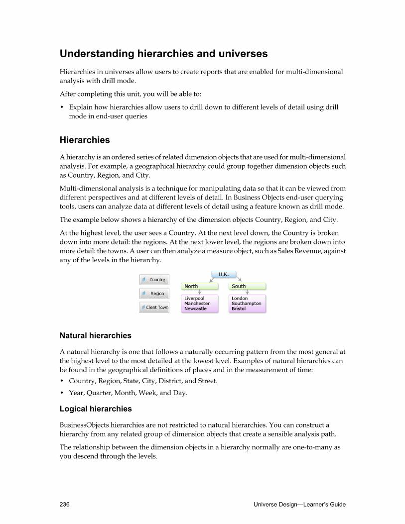
Understanding hierarchies and universesHierarchies in universes allow users to create reports that are enabled for multi-dimensionalanalysis with drill mode.
After completing this unit, you will be able to:
• Explain how hierarchies allow users to drill down to different levels of detail using drillmode in end-user queries
Hierarchies
Ahierarchy is an ordered series of related dimension objects that are used formulti-dimensionalanalysis. For example, a geographical hierarchy could group together dimension objects suchas Country, Region, and City.
Multi-dimensional analysis is a technique for manipulating data so that it can be viewed fromdifferent perspectives and at different levels of detail. In Business Objects end-user queryingtools, users can analyze data at different levels of detail using a feature known as drill mode.
The example below shows a hierarchy of the dimension objects Country, Region, and City.
At the highest level, the user sees a Country. At the next level down, the Country is brokendown into more detail: the regions. At the next lower level, the regions are broken down intomore detail: the towns. A user can then analyze ameasure object, such as Sales Revenue, againstany of the levels in the hierarchy.
Natural hierarchies
A natural hierarchy is one that follows a naturally occurring pattern from the most general atthe highest level to the most detailed at the lowest level. Examples of natural hierarchies canbe found in the geographical definitions of places and in the measurement of time:• Country, Region, State, City, District, and Street.
• Year, Quarter, Month, Week, and Day.
Logical hierarchies
BusinessObjects hierarchies are not restricted to natural hierarchies. You can construct ahierarchy from any related group of dimension objects that create a sensible analysis path.
The relationship between the dimension objects in a hierarchy normally are one-to-many asyou descend through the levels.
Universe Design—Learner’s Guide236

For example, one country has many towns; one town has many showrooms; one showroomhas many franchises.
237Using Hierarchies—Learner’s Guide

Working with hierarchiesAfter defining hierarchies, the next step is to understand how to deploy them in the universe,and work with hierarchies and scope of analysis in Web Intelligence Rich Client.
After completing this unit, you will be able to:
• View default hierarchies in a universe• Set the scope of analysis in aWeb Intelligence RichClient document using a default hierarchy• Create a custom hierarchy• Create time hierarchies
Default hierarchies
Adefault hierarchy contains all the dimension objects in a class in the order they are presentedin that class. It is based on the order of the objects within the class.
As the name suggests, a default hierarchy is automatically inferred by BusinessObjects end-userquerying tools whenever you have at least one dimension object in a class.
It is therefore important to organize dimension objects hierarchically in a class.
In this example, you can see that the dimension objects in each class follow an order from themost general to the most specific.
Using this method of organizing your dimension objects in their classes is the key to settingup usable default hierarchies.
Universe Design—Learner’s Guide238

To view the default hierarchies
1. There are two methods to view the default hierarchies:• Select Tools ➤ Hierarchies from the menu bar.• Click theHierarchies toolbar button.
This opens theHierarchies Editor dialog box:
You cannot add or remove objects from classes in theHierarchies Editor.
You can use theHierarchies Editor to create custom hierarchies.
2. Click the + box next to any class if you want to see the dimension objects organized in thesehierarchies.
3. Click Cancel to close theHierarchies Editor dialog box.
To test a default hierarchy
As with other components of a universe, hierarchies can be tested in Web Intelligence RichClient, to check that they function as expected.1. In Web Intelligence Rich Client, create a new document. Select the relevant universe.
2. Select an object that is the highest level of one of the hierarchies, andmove it into theResultObjects pane.
3. Select a suitable measure object, and double-click it to add it to the Result Objects pane.
4. Click the Show/Hide Scope of Analysis pane button on the Web Intelligence Rich ClientQuery Panel toolbar.
239Using Hierarchies—Learner’s Guide

This opens the Scope of Analysis pane.
The Scope of Analysis pane allows users to set up the query for drill analysis. All thedimensions selected for the query are highlighted here, within their default hierarchies. Inorder to allow users to drill down the hierarchy from one level to another, without havingto modify the query, you can set the scope of analysis before the query is actually executed.
Note: You can manually drag the objects you want to drill down to in this pane. In thiscase, the Custom value appears in the Scope of Analysis level drop-down list.
5. To define default levels of scope of analysis, select the level drop-down list in the Scope ofAnalysis, and click the arrow to select the scope of analysis levels.
The levels you define in the scope of analysis determines how many objects from thehierarchy is included in the query, and therefore howmany levels of detailed data is returnedin the Web Intelligence Rich Client document.
6. Select the required level from the drop-down list.
The Scope of Analysis pane contains further dimensions, indicating the level down optionyou have just selected.
Thismeans that they are included in the query, and themeasure relevant to these two objectsare calculated and stored in the document’s microcube.
7. Click Run Query to execute the query.
Values returned by the two dimension objects are not immediately be projected in the tablethat is displayed, but the objects can be seen listed in theData tab of the Report Manageron the side.
As soon as a user decides to switch to drill mode, the data ismade available for drill analysis.
8. Click theDrill button in the Reporting toolbar to display the report in drill mode.
Note: The report tab at the bottom of the Rich Client main window now shows the nameReport 1with a drill mode icon.
Universe Design—Learner’s Guide240
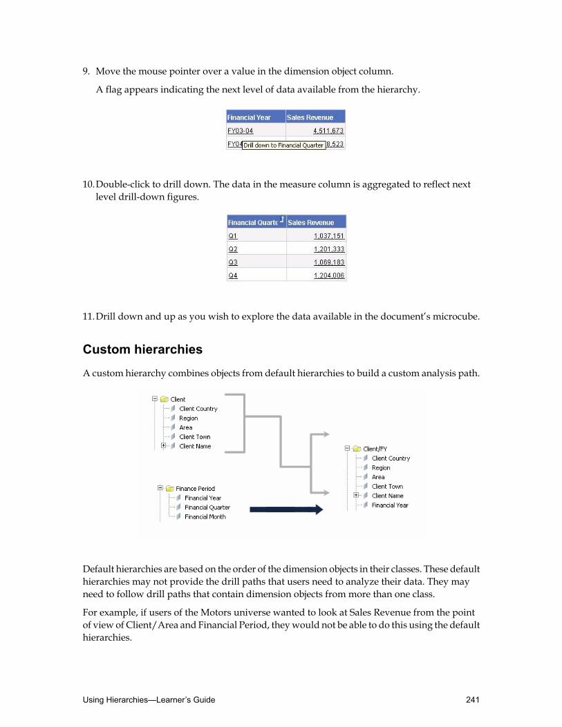
9. Move the mouse pointer over a value in the dimension object column.
A flag appears indicating the next level of data available from the hierarchy.
10.Double-click to drill down. The data in the measure column is aggregated to reflect nextlevel drill-down figures.
11.Drill down and up as you wish to explore the data available in the document’s microcube.
Custom hierarchies
A custom hierarchy combines objects from default hierarchies to build a custom analysis path.
Default hierarchies are based on the order of the dimension objects in their classes. These defaulthierarchies may not provide the drill paths that users need to analyze their data. They mayneed to follow drill paths that contain dimension objects from more than one class.
For example, if users of the Motors universe wanted to look at Sales Revenue from the pointof view of Client/Area and Financial Period, theywould not be able to do this using the defaulthierarchies.
241Using Hierarchies—Learner’s Guide

As universe designer, you can build a permanent custom hierarchy as part of the universe. Asa result, the hierarchy is available across documents to all users.
In the analysis phase of the universe development process, the designer identifies those customhierarchies that are to be used regularly and creates them in Universe Designer as permanentcustom hierarchies.
To create a custom hierarchy
1. There are two methods to create a custom hierarchy:• Select Tools ➤ Hierarchies from the menu bar.• Click theHierarchies toolbar button.
This opens theHierarchies Editor dialog box:
2. ClickNew.
A new folder appears in the Custom Hierarchies pane.
3. Type a name for the custom hierarchy as the folder name, and press Enter.
4. In the left panel of theHierarchies Editordialog box, click the + box of the default hierarchiesthat contain the dimension objects you want to include in the custom hierarchy.
The default hierarchy dimension objects appear.
5. There are several methods to add the dimension objects to the custom hierarchy:• Select the object that you want to appear in the custom hierarchy, and click Add.• Select multiple objects by holding the Ctrl key down, and click Add.• Drag and drop the required objects to the new custom hierarchy folder.
The selected objects appear in the custom hierarchy.
Note: The dimension objects may not be in the order you require. You canmove the objectsup and down the list by clicking them and then clicking theMove Up orMove Downbuttons. Alternately, you can use the drag-and-drop technique.
6. ClickOK to save the changes to the hierarchies and close theHierarchies Editor dialog box.
7. Save the universe.
The effect of custom hierarchies on default hierarchies
In Web Intelligence Rich Client, if you switch theQuery Panel'sData tab toDisplay byhierarchiesmode, before you create any custom hierarchies in Universe Designer, you see thatthe list of hierarchies is shown in the same order as the objects in theDisplay by objects mode:both show a full list of default hierarchies.
However, when you create a custom hierarchy, theDisplay by hierarchiesmode lists only thecustom hierarchies while theDisplay by objectsmode shows all objects made available to theuser.
Universe Design—Learner’s Guide242

At first, this appears to be a problem. However, the effect of creating a custom hierarchy isactually very useful because it provides a mechanism for selectively producing hierarchies forend users.
Because a default hierarchy is always created for any class where a dimension object exists, itmay be that there are some default hierarchies that you do not want users to use as drill paths.This mechanism can be used to exclude such default hierarchies.
Once you decide to create custom hierarchies, youmust copy any of the defaults that youwantto keep over to the right-hand side list box. Even if you do not want to create new ones, toexclude the default hierarchies that you do not want users to use as drill paths, you must copythe useful ones over.
In order to make any change at all in the hierarchies, you either start over by creating newcustomhierarchies or you copy only the useful default hierarchies into the CustomHierarchiesselection list.
To selectively make default hierarchies available to users
This topic discusses how to add selected default hierarchies to the list of custom hierarchies inUniverse Designer.1. There are two methods to create a custom hierarchy:
243Using Hierarchies—Learner’s Guide

• Select Tools ➤ Hierarchies from the menu bar.• Click theHierarchies toolbar button.
This opens theHierarchies Editor dialog box.
2. Drag and drop only the default hierarchy folders you want the users to use as drill pathsfrom the left panel of theHierarchies Editor dialog box to the right panel.
Note: Whenmore than one hierarchy startswith the samedimension object path but divergesat a lower level of the hierarchy, the default path in the user module is the one that is higherin the list (if dimensions from both hierarchies are included in the query). You can alter thisdefault priority by changing the order of the hierarchies in the CustomHierarchies list. Youcan do this using theMove Up andMove Down buttons, or using the drag-and-droptechnique.
Note: When you add default hierarchies to the Custom Hierarchies list, it is good practiceto position the true custom hierarchy, if any, at the bottom of the list.
3. ClickOK to save the changes to the hierarchies and close theHierarchies Editor dialog box.
4. Save the universe.
Time hierarchies
One of the most common requirements for data analysis is to provide facilities for analysisagainst different time periods.
Time is a special case because all the information for the dimension objects that make up thehierarchy can come from a single column in a database. In most other cases, each dimensionobject infers a separate database column.
Universe Design—Learner’s Guide244

This is achieved by using SQLdate scalar functions to extract the day,month, year, and possiblyquarter from a single database column of a date type.
When you create a time hierarchy, you are still creating a default hierarchy, in which the levelsdepend on the order of the dimension objects. You create the standard time structure by orderingthe objects Year, Quarter, Month, and Week. The only difference with time hierarchies is theway in which you create the objects.
Creating time hierarchies
There are three methods of creating a time hierarchy. Each method has advantages anddisadvantages for both the designer and the user. The three methods are:• Automatic time hierarchies.
• Using database functions.
• Table-based time hierarchies.
To create an automatic time hierarchy
Using this method, Universe Designer automatically creates the dimension object definitionsneeded for a time hierarchy from a single date object.
Automatic time hierarchies can only be applied to objects with date type.1. Double-click a date object to open the Edit Properties dialog box.
Note that the Type field is set toDate.
2. Click the Properties tab. With the field type set toDate, the Automatic Time Hierarchybutton is shown in the Qualification zone.
245Using Hierarchies—Learner’s Guide

3. Click theAutomatic TimeHierarchy button to open theAutomatic TimeHierarchy dialogbox.
4. Select the check boxes for the time-related dimension objects you want to create and editthe names of the dimension objects, if required.
5. ClickOK to close the Automatic Time Hierarchy dialog box.
6. If necessary, alter other object properties as required.
7. ClickOK to close the Edit Properties dialog box.
In the Universe pane, the original date object has a plus next to it, indicating that otherobjects are attached to it. These are the automatically created time dimension objects.
8. Click the + box to view and check the objects attached to the date object.
Note: You can see that the arrangement of the objects is not as youmight expect. The originaldate object is at the top of the hierarchy, and the other time objects appear to be subsidiaryobjects to it. From this, it is apparent that there are two further disadvantages to thismethodof creating time dimension objects. First, when a user sees a + box against an object, theywill think that detail objects are attached to it. Second, the objects are not orderedhierarchically in the class, and, as a consequence, this might lead to confusion as to whichis the highest-level object in the class.
9. Double-click one of the automatically created time dimension objects (year, quarter, ormonth) to view the Edit Properties dialog box for the object.
Universe Design—Learner’s Guide246

Note: The object properties cannot be edited. This is another disadvantage. However, youcan also see one of the key advantages of using thismethod to create time dimension objects:the SQL inferred includes the scalar function used to extract the correct element of the date.
10.ClickOK to close the Edit Properties dialog box.
11.Click theHierarchies toolbar button to open theHierarchies Editor dialog box.
Notice that in theDefault Hierarchies list, there are two new default hierarchy classes, anempty one bearing the name of the original class, and another bearing the name of the classappended with the name of the original date object.
12.Click the + box next to the class/object-named default hierarchy.You can see that the time hierarchy objects are correctly ordered despite the order of thedimension objects in the class.
13.Close theHierarchies Editor dialog box.
14.Save the universe.
Testing automatic time hierarchies
Automatic time hierarchies are tested in the same way as any other hierarchy. However, thereis one thing to note about such a test.
When you drill down to the bottom of the time hierarchy, the quarters and the months areidentified simply as numbers, 1 to 4 for the quarters and 1 to 12 for the months.
247Using Hierarchies—Learner’s Guide

This can be confusing or unsatisfactory to end users. A better idea is to precede the numberswith a character string such as quarter or month. However, as you have already seen, it isimpossible to edit a time dimension object that is created using the automated method.
Advantages and disadvantages of automatic time hierarchies
This section lists the advantages and disadvantages for using automatic time hierarchies.
Advantages
• It is a fairly quick and easy way to set up a time hierarchy.
• Automatically creates the SQL SELECT statement using the appropriate scalar functions forthe RDBMS of the target database.
Disadvantages
• Does not give the designer any control over the layout of the dimension objects in theUniverse pane.
• Does not give the designer any control over the format of the data in the query report.
• The layout of the dimension objects in the universe can be confusing to users, who normallyexpect to see detail objects under dimension objects.
• The format of the report can be confusing to users.
• An LOV can only be applied to the original date object, not to individual time dimensionobjects.
All the negative points listed above can be avoided if anothermethod of creating time dimensionobjects is used.
Time hierarchies based on database functions
You can use the scalar date functions to create time dimension objects manually.
Note: However, the set of scalar functions used to extract elements of a database varies witheach RDBMS.
To create a time hierarchy using database functions
1. Create a new class or subclass with an appropriate name.
Universe Design—Learner’s Guide248
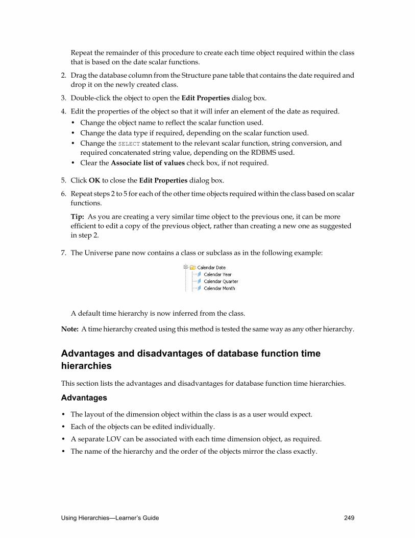
Repeat the remainder of this procedure to create each time object required within the classthat is based on the date scalar functions.
2. Drag the database column from the Structure pane table that contains the date required anddrop it on the newly created class.
3. Double-click the object to open the Edit Properties dialog box.
4. Edit the properties of the object so that it will infer an element of the date as required.• Change the object name to reflect the scalar function used.• Change the data type if required, depending on the scalar function used.• Change the SELECT statement to the relevant scalar function, string conversion, and
required concatenated string value, depending on the RDBMS used.• Clear the Associate list of values check box, if not required.
5. ClickOK to close the Edit Properties dialog box.
6. Repeat steps 2 to 5 for each of the other time objects requiredwithin the class based on scalarfunctions.
Tip: As you are creating a very similar time object to the previous one, it can be moreefficient to edit a copy of the previous object, rather than creating a new one as suggestedin step 2.
7. The Universe pane now contains a class or subclass as in the following example:
A default time hierarchy is now inferred from the class.
Note: A time hierarchy created using thismethod is tested the sameway as any other hierarchy.
Advantages and disadvantages of database function timehierarchies
This section lists the advantages and disadvantages for database function time hierarchies.
Advantages
• The layout of the dimension object within the class is as a user would expect.
• Each of the objects can be edited individually.
• A separate LOV can be associated with each time dimension object, as required.
• The name of the hierarchy and the order of the objects mirror the class exactly.
249Using Hierarchies—Learner’s Guide

Disadvantages
• It takes longer to create the objects of the time hierarchy than when using the automatictime hierarchy method.
• The person designing the universe needs to know the relevant scalar functions and how touse them.
Tip: If you do not know the relevant scalar functions, you could initially create the time objectswithin a class using the automatic time hierarchy method. Then you could note the scalarfunctions automatically inferred, remove the automatically created objects, and recreate themusing the database function method.
Table-based time hierarchies
The automatic time hierarchy and database functions methods of creating a time hierarchy areappropriate when you want to create calendar-based time dimension objects. However, theyare inappropriate when you want to create time dimension objects based on different timeperiods.
Another way of creating time dimension objects is to add a time-range table to the databasewith columns and data as in the following example. This table can then be added to the structureand its columns used to create time dimension objects. This is a good way of coping withfinancial periods that do not coincide with the calendar year.
To create a table-based time hierarchy
1. Add the time period table to the universe structure.
2. Insert a theta join between the start and end range columns of the time period table and anappropriate date column of another table.
An example of this is shown below:
Universe Design—Learner’s Guide250

3. Create a new class with an appropriate name.
4. Create the time objects required. In each instance, you do not need to use scalar functions.The SELECT statement of each object needs only to infer a database column name. Therefore,it would be more efficient to use the automatedmethod of creating objects (drag and drop).
When the objects have been created, the class appears as in the example below:
A default time hierarchy is now inferred from the class.
5. Save the universe.
Note: A time hierarchy created using this method is tested in the same way as any otherhierarchy.
Advantages and disadvantages of table-based time hierarchies
This section lists the advantages and disadvantages of table-based time hierarchies .
Advantages
• It is a good method of creating time dimension objects for time periods other than calendarperiods.
• The layout of the dimensions within the class is as a user would expect.
• Each of the objects can be edited individually.
• A separate LOV can be associated with each time dimension object, as required.
• The name of the hierarchy and the order of objects mirror the class exactly.
Disadvantages
• The additional join reduces the efficiency of an inferred SQL statement.
251Using Hierarchies—Learner’s Guide

Activity: Using hierarchies
Objective
• Infer default hierarchies and create custom hierarchies for your Motors universe.
Note: Switch back to default hierarchies if you have followed along during this lesson.
Instructions
1. To view all hierarchies, click the hierarchy button. Remove all custom hierarchies in theCustom selection list.
2. Check that the hierarchical order of the dimension objects in the Client class is based ongeography.The geographic hierarchy is: Country -> Region -> Area -> Town.
3. Save your universe locally, and then test the default hierarchy in Web Intelligence RichClient.
4. Create the following dimension objects using the automatic time hierarchy method: SaleYear, Sale Quarter, and Sale Month.
5. Save the universe locally, and then test the resulting hierarchy in Web Intelligence RichClient.When you run the query, view the SQL and note the scalar function used.
6. Using the automatic time hierarchy method poses some limitations.Remove the automatically created Sale Year, Sale Quarter, and Sale Month objects, andreplace them with manually created objects, using numeric database scalar functions:• Sales Year:
{fn year(SALE.SALE_DATE)}
• Sales Quarter:{fn quarter(SALE.SALE_DATE)}
• Sales Month:{fn month(SALE.SALE_DATE)}
7. Create the following dimension objects manually in the Rental Dates subclass, usingalphanumeric database scalar functions and formatting: Rental Year, Rental Quarter, andRental Month.• Rental Year:
'Calendar Year ' + datename(YYYY,RENTAL.SALE_DATE)
• Rental Quarter:'Q ' + datename(Q,RENTAL.SALE_DATE)
• Rental Month:datename(mm,RENTAL.SALE_DATE)
Universe Design—Learner’s Guide252

8. Check that the order of the dimension objects in the Financial Period class is based on time.
9. Save your universe locally, and test the resulting hierarchies inWeb Intelligence Rich Client.
10.Prestige Motors wants to analyze clients geographically (by Country, Region, and Town)but then further analyze the breakdown of client expenditure by financial year.Create a customhierarchy to allowusers to do this by including the Country, Region, Town,and Financial Year objects in the hierarchy.
11.Make the following default hierarchies available to the user:• Car• Day Rental Charges• Showroom• Financial Period• Rental Dates• Sale Dates
12.Save your universe locally, and test the resulting hierarchy inWeb Intelligence Rich Client.
13.Sales people want to drill down to a model using a specific drill path. In the bottom of yourcustom hierarchy list, create a hierarchy to allow this drill path using the following objects:• Showroom Country• Showroom Name• Maker• Model
14.Save your universe locally, and then test the resulting hierarchy in Web Intelligence RichClient.
253Using Hierarchies—Learner’s Guide

Quiz: Using hierarchies1. A _____________ hierarchy is the hierarchy based on the order of the objects within the
class.○ a) Default○ b) Custom
2. What are two advantages of automatic time hierarchies?
Universe Design—Learner’s Guide254

Lesson summaryAfter completing this lesson, you are now able to:
• Understand hierarchies and universes• Work with hierarchies
255Using Hierarchies—Learner’s Guide

Universe Design—Learner’s Guide256

Lesson 11Using Lists of Values
Lesson introductionThis lesson explains how you can add, modify, or remove a list of values (LOV) for an object.It also introduces how to create a cascading list of values in Universe Designer and how to usethem in Web Intelligence Rich Client.
After completing this lesson, you will be able to:
• Create a list of values• Work with LOVs in Universe Designer• Create a cascading LOV
257Using Lists of Values—Learner’s Guide

Creating a list of valuesIn order to effectively assign a list of values to universe objects, it is necessary to familiarizeyourself with what a list of values is and how it is applied in the universe, and how it is usedin Web Intelligence Rich Client.
After completing this unit, you will be able to:
• Define a list of values (LOV)• Use a list of values in Web Intelligence Rich Client
What is a list of values?
When you create a dimension or detail object in Universe Designer, it is automatically assignedan associated list of values, or LOV. This list does not physically exist when you create an object,but by default the object has the ability to query the database to return a list of its values whenused to build a query.
Lists of values are based on the results of a SELECT Distinct query on the column or columnsheld in the Select field in the object’s Edit Properties dialog box. If you select the Export withUniverse option in the Associate a List of Values zone of the Properties tab, the list of valuesis converted to XMLwhen you export the universe, and then stored in a .unw file in the CentralManagement Server (CMS).
The first time a list of values is used to filter results returned by a query, the LOV is stored inan encrypted file on the local file server in the sessions folder.
As you create objects in the universe, use the following questions as a guide to help you decidewhether to associate an LOV to an object or not:• Do the users need to see a list of values for this object? Are they likely to want to apply
query filters or conditions on this object?
• Is the data dynamic or static? Does the data get updated frequently?
• How long does it take to run the SELECT Distinct query?
• What does the list need to include?
Using a list of values (LOV)
When users build queries, they can define query filters to restrict the amount of data returnedby a specific object used in the query. To do this, they view the list of values for that object inorder to specify which value(s) is returned. The LOV for the object appears in the Filter orEditor, which helps the user choose the terms for the filter.
For example, a manufacturer object with the SELECT clause for the manufacturer name columnhas an LOV that contains all the available distinct carmanufacturer’s names. A userwhowantsto limit the query to a singlemanufacturer could select that name for the query filter by choosingit from the LOV.
Universe Design—Learner’s Guide258

Working with LOVs in Universe DesignerAfter familiarizing yourself with a list of values, a list that contains the distinct data valuesassociated with an object, the next step is to understand how to create and assign LOVs to theappropriate objects in a universe.
After completing this unit, you will be able to:
• Associate an LOV with an object• View the contents of an LOV• Set options for generating an LOV• Modify the contents of an LOV• Create a hierarchical view of an LOV
Associating an LOV with an object
By default, an LOV is attached to every dimension and detail object that is created in UniverseDesigner.When you create a dimension or detail object in UniverseDesigner, it is automaticallyassigned an associated list of values, or LOV. This list does not physically exist when you createan object, but by default the object has the ability to query the database to return a list of itsvalues when used to build a query.
There are three things to keep in mind, as a universe designer, when deciding whether or notto associate an LOV to an object:• An LOV is based on a SELECT Distinct query that is fired at the target database. This could
have potential performance implications for the efficiency of Business Objects end-userquerying tools.
• The only purpose for creating an LOV is to assist the end user in choosing an operand valuefor a query filter.
• The LOV only holds values that exist within the database.
It is therefore recommended that you do not provide an LOV for the following types of objects:• All measure objects.• Any object where the LOV consists of a large number of values.• Any object where the list on its own would be meaningless.
To view an object’s default LOV properties
1. Double-click the object to open the Edit Properties dialog box for the object.
2. Click the Properties tab.
259Using Lists of Values—Learner’s Guide
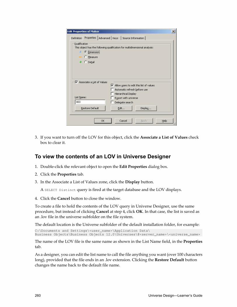
3. If you want to turn off the LOV for this object, click the Associate a List of Values checkbox to clear it.
To view the contents of an LOV in Universe Designer
1. Double-click the relevant object to open the Edit Properties dialog box.
2. Click the Properties tab.
3. In the Associate a List of Values zone, click theDisplay button.
A SELECT Distinct query is fired at the target database and the LOV displays.
4. Click the Cancel button to close the window.
To create a file to hold the contents of the LOV query in Universe Designer, use the sameprocedure, but instead of clicking Cancel at step 4, clickOK. In that case, the list is saved asan .lov file in the universe subfolder on the file system.
The default location is the Universe subfolder of the default installation folder, for example:C:\Documents and Settings\<user_name>\Application Data\Business Objects\Business Objects 12.0\Universes\@<server_name>\<universe_name>
The name of the LOV file is the same name as shown in the List Name field, in the Propertiestab.
As a designer, you can edit the list name to call the file anything you want (over 100 characterslong), provided that the file ends in an .lov extension. Clicking the Restore Default buttonchanges the name back to the default file name.
Universe Design—Learner’s Guide260

Setting options for generating LOVs
By default, the first time that an LOV is used in a user login session, the system fires a queryat the target database and uses the results to populate the list. Thereafter, the .lov file from thisquery is referred to each time the LOV is used.
However, you can alter the strategy for refreshing the list by selecting options from theAssociatea List of Values zone, in the Edit Properties dialog box.
Automatic refresh before use
If you select this check box, the system sends the SELECT Distinct query to the target databaseevery time the user selects the LOV. This refreshes the contents of the list muchmore frequentlythan the default strategy, where the list is refreshed only the first time it is used in a user loginsession.
It is recommended that you select the Automatic refresh before use check box if the contentsof the list are dynamic and frequently changing. If the contents of the list are stable andunchanging, you can increase speed and efficiency by clearing this check box.
Export with universe
If you select the Export with universe check box, the list of values is converted to XML whenthe universe is exported, and stored in a .unw file. This file is stored in the BusinessObjectsCentral Management Server (CMS).
Delegate search
The delegated list of values search allows you to delegate the search of values in an LOV tothe database.
This feature:• Prevents the LOV from loading automatically.• Restricts the data set returned.• Improves performance by limiting the load time.
Instead, the report user can perform a search for a pattern within the database.
This option can be helpful when using an SAP BW data source. An SAP BW query can containmore than ten variables, which means that ten or more lists of values can be loaded. Loadingand refreshing lists of values can have an important impact on performance.
261Using Lists of Values—Learner’s Guide

TheDelegate Search option on the list of values properties presents the user with an emptylist of values at query run time. The user enters search criteria to limit the number of valuesreturned in the list of values.
Note: TheDelegate Search option is not supported for cascading lists of values.
Modifying the contents of the LOV
In Universe Designer, you can modify the contents of the list in two ways:• Remove values from the list by creating a filter.
• Add data to the list by adding columns to the list.
The remaining two options, Allow users to edit this list of values andHierarchical Display,are not available for users creating reports with Web Intelligence and Web Intelligence RichClient.
To apply a condition to an LOV
1. In Universe Designer, in the object’s Edit Properties tab (in the Associate a List of Valueszone), click Edit to the left of theDisplay button.
The Universe DesignerQuery Panel displays, showing the default query for the LOV. Theactive object is listed in the Result Objects.
2. Drag an object that youwant to serve as a condition on the list of values for the active objectover to the Conditions pane.
3. Double-click an operator in theOperators pane.
4. Double-click an operand in theOperand pane.
5. Select or type values as required.
6. Click Run to save the condition and close the Universe DesignerQuery Panel.
7. ClickDisplay to view the restricted list of values.If a blank list appears, click Refresh. The values appear in the list.
8. ClickOK to accept the modified list.
The .lov file in the universe subfolder updates with the modified list. This is the LOV thatthe end users see when they use the edited object in a query.
Editing the LOVs for the entire universe
If you want to view all the objects in the universe that have LOVs associated with them, andpossibly edit some of these LOVs at the same time, you can edit the lists from the UniverseDesigner Toolsmenu.
Universe Design—Learner’s Guide262
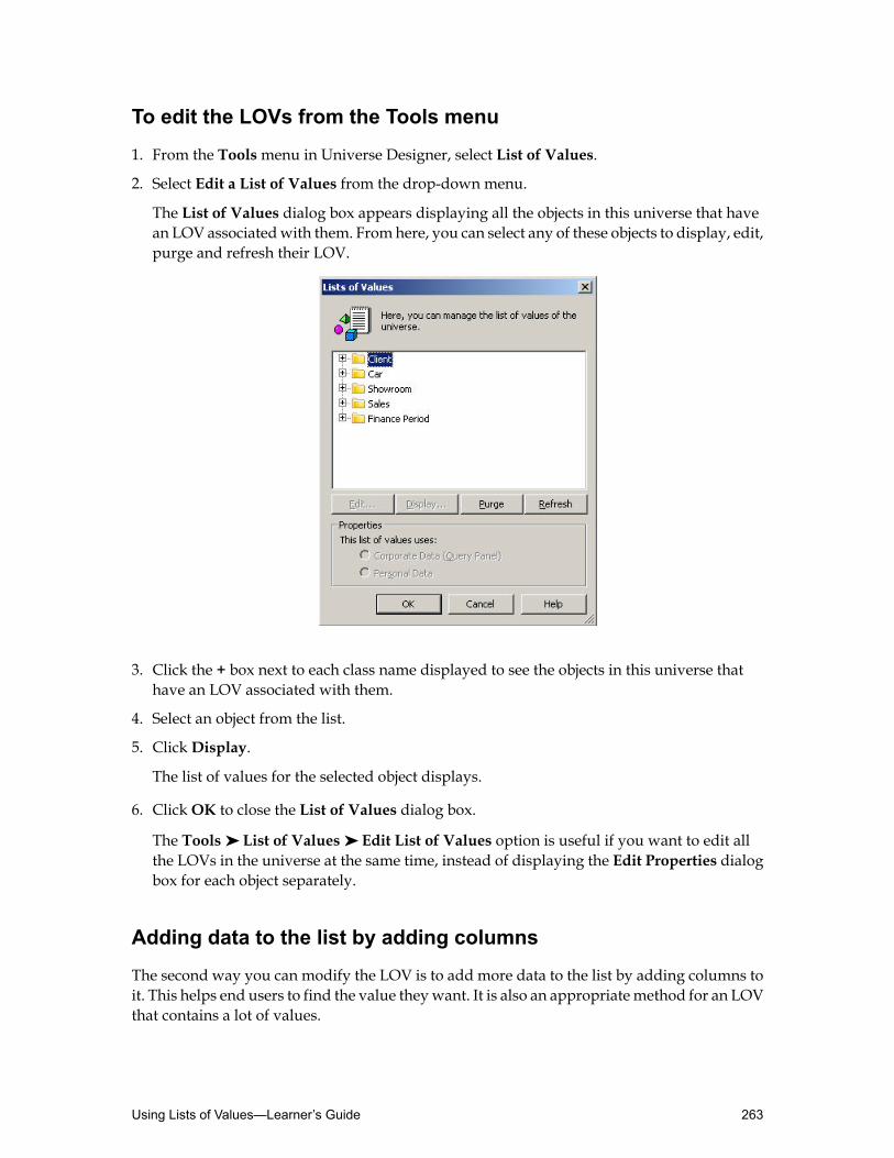
To edit the LOVs from the Tools menu
1. From the Toolsmenu in Universe Designer, select List of Values.
2. Select Edit a List of Values from the drop-down menu.
The List of Values dialog box appears displaying all the objects in this universe that havean LOV associatedwith them. From here, you can select any of these objects to display, edit,purge and refresh their LOV.
3. Click the + box next to each class name displayed to see the objects in this universe thathave an LOV associated with them.
4. Select an object from the list.
5. ClickDisplay.
The list of values for the selected object displays.
6. ClickOK to close the List of Values dialog box.
The Tools ➤ List of Values ➤ Edit List of Values option is useful if you want to edit allthe LOVs in the universe at the same time, instead of displaying the Edit Properties dialogbox for each object separately.
Adding data to the list by adding columns
The second way you can modify the LOV is to add more data to the list by adding columns toit. This helps end users to find the value theywant. It is also an appropriatemethod for an LOVthat contains a lot of values.
263Using Lists of Values—Learner’s Guide

To add additional columns to an LOV
1. Double-click an object to open the Edit Properties tab.
2. Click the Properties tab.
3. Select Edit (in the Associate a List of Values zone).
The Universe DesignerQuery Panel displays.
4. Drag the objects youwant to place in the hierarchy into theResult Objects pane to the rightof the existing object and place the respective sorts on them.
5. Click Run to save the LOV query and close the Universe DesignerQuery Panel.
6. On the Properties tab of the object’s Edit Properties dialog box (in the Associate a List ofValues zone), click theDisplay button to see the LOV.
Note: If the list is blank, click the Refresh button to update the list.
Universe Design—Learner’s Guide264

Creating a cascading LOVA cascading LOV is a feature in Universe Designer that allows you to associate an LOV to aseries of objects defined in a hierarchy. When a user applies a prompted query filter to one ofthe objects used in the cascading LOV,Web Intelligence orWeb Intelligence RichClient promptsthe user to select a value for each level of the hierarchy.
After completing this unit, you will be able to:
• Set up a cascading LOV• Use the cascading LOV in Web Intelligence Rich Client
Setting up a cascading LOV
A cascading LOV is a sequence of lists of values associated with a hierarchy of objects in auniverse. As universe designer, you define prompts for each hierarchy level andwhen the useradds one of the objects to a query, the query prompts the user to select a value for each level.
Universe designers build the prompt(s) in the object definition, and report designers and powerusers use it when they create and refresh reports using queries.
A universe designer defines the universe so that the user is always required to answer a seriesof prompts to specify the values in a hierarchy of dimensions to be displayed in the report.Only the data concerning the selected values is returned to the microcube.
Users can create a query that builds one of the objects into a prompted query filter. The Promptsdialog box displays the list of values for all the objects you placed in the cascading LOV inUniverse Designer, in reverse order.
265Using Lists of Values—Learner’s Guide

To build a cascading LOV on an object
1. From the Toolsmenu in Universe Designer, select List of Values.
2. Select Create cascading Lists of Values from the drop-down menu.
The Create Cascading List of Values dialog box appears.
3. Open the appropriate class and double-click the object to move it into the Cascading Listof Values list.By default, text appears in the Prompt Text zone to set the text that users see if this objectis used in a prompted query filter after you add the next object.
4. Double-click additional objects that need to appear in hierarchical order in the cascadinglist of values.Edit the prompt text if required.
5. Verify that theHierarchical View check box is selected.
6. ClickGenerate LOVs to create the list of values.If LOVs already exist for the selected objects, you are prompted with a message askingwhether you want to overwrite the existing values.
7. ClickOK.The Create Cascading List of Values dialog box closes.
Universe Design—Learner’s Guide266

8. Save the universe.
To test the cascading LOV in Web Intelligence Rich Client
Now that you have assigned LOVs to objects that are grouped together in a hierarchy as acascading LOV, you can create a query that builds one of the objects into a prompted queryfilter.1. In Web Intelligence Rich Client, build a query and create a prompt on one of the objects in
the cascading LOV.
2. Click Run Query.The Prompts dialog box appears. The Prompts dialog box displays the list of values for allthe objects you placed in the cascading LOV in Universe Designer, in reverse order.
Note: If you are sure you know the exact value that interests you, you can always type inthe Type a value field.
3. Scroll down the list of values and click the + box to expand that folder.
4. Expand the further + boxes to select the lowest level value for your query.The little arrow displayed next to the prompt text at the top of the Prompts dialog boxchanges to a green check mark and the value you have chosen appears in the prompt.
5. Click Run Query to create the report.The report displays the selected values.
Activity: Using a cascading LOV in Web Intelligence Rich Client
Objective
• Associate a Cascading LOV to an object.
Instructions
1. InUniverseDesigner, create a cascading LOVusing theMaker,Category of Car, andModelobjects in the Car class.
2. Save your universe locally.
3. Build a query in Web Intelligence Rich Client that shows the number of cars sold pershowroom and prompts the users to select the Category of Car that they want to see in thereport.
Note: At the end of this activity, please remove the Cascading List of Values using thefollowing steps:• In Universe Designer, change the object definition to associate a standard list of values
for all objects in the Car class.
• Save your universe locally.
267Using Lists of Values—Learner’s Guide

Quiz: Using lists of values1. By default what values are contained in a list of values (LOV)?
2. What are three things that a universe designer should keep inmindwhen decidingwhetherto associate an LOV with an object?
3. For what types of objects is it recommended not to provide an LOV?
Universe Design—Learner’s Guide268

Lesson summaryAfter completing this lesson, you are now able to:
• Create a list of values• Work with LOVs in Universe Designer• Create a cascading LOV
269Using Lists of Values—Learner’s Guide

Universe Design—Learner’s Guide270

Lesson 12Creating Derived Tables and Indexes
Lesson introductionA derived table is a dynamic, virtual table that you create within the universe structure. Itallows you to transfer more of the processing load from the report server to the database andimprove query execution performance.
Index awareness is the ability to take advantage of the database indexes on key columns tospeed data retrieval. The objects that you create in the universe are based on database columnsthat are meaningful to an end user.
After completing this lesson, you will be able to:
• Use derived tables• Apply index awareness
271Creating Derived Tables and Indexes—Learner’s Guide

Using derived tablesThis unit explains derived tables and how you create them as dynamic, virtual tables in theuniverse.
After completing this unit, you will be able to:
• Understand the advantage of adding derived tables to your universe structure• Insert a derived table in the universe
What is a derived table?
A derived table is a dynamic, virtual table that you create within the universe structure. Itconsists of a set of SQL statements that you create in Universe Designer, and that you can thenuse as a logical table to create objects.
In the derived table’s SQL set, you can put a SELECT statement in place of a table name in theFROM clause. The SQL set can also contain embeddedprompts, and you can create joins betweenthe virtual derived table and the physical tables, just as you can with other tables.
Derived tables are similar to views in the database, but as they are defined in the universe, theygive universe designers more flexibility. You can see a derived table as a query that can bereferenced as a table. The table definition SQL is inserted into an end-user query at run time.
Note: As it is a query and not a physical table, it is important to understand that the sameperformance issues that can affect queries can also affect derived tables.
Derived tables can be used tomerge data together fromdifferent tables,whenuniverse designersare unable to conform the underlying data source, and want to normalize or denormalize theuniverse schema.
Adding derived tables
Derived tables appear in your Universe Designer schema in exactly the same way as normaldatabase tables, but the workflow for creating them is different.
To create a derived table
1. Select Insert ➤ Derived Tables.
TheDerived Tables dialog box displays.
2. Type the table name in the Table Name field.
3. Build the table SQL in the box beneath the Table Name field.You can type the SQL directly or use the Tables and Columns, Operators and Functionsselection lists to build it.
Universe Design—Learner’s Guide272
Note: When using an aggregation function, or any other SQL function in the SQL syntax,it is important to alias the column that contains the calculation. Universe Designer usesthese aliases as the column names in the derived table.
4. Click Check Syntax to parse and validate your SQL.
5. ClickOK.The derived table appears in the schema, below the original physical database table, at thebottom left corner.
Tip: Use List Mode to locate your derived table.
6. Join the table to a table in the existing schema.If contexts have been applied to the schema, make sure the newly inserted join is includedin at least one context.
7. Build objects based on the derived table columns in exactly the same way you do withregular tables.
8. Save the universe.
To create a derived table
1. Select Insert ➤ Derived Tables.
TheDerived Tables dialog box displays.
2. Type the table name in the Table Name field.
3. Build the table SQL in the box beneath the Table Name field.You can type the SQL directly or use the Tables and Columns, Operators and Functionsselection lists to build it.
Note: When using an aggregation function, or any other SQL function in the SQL syntax,it is important to alias the column that contains the calculation. Universe Designer usesthese aliases as the column names in the derived table.
4. Click Check Syntax to parse and validate your SQL.
5. ClickOK.The derived table appears in the schema, below the original physical database table, at thebottom left corner.
Tip: Use List Mode to locate your derived table.
6. Join the table to a table in the existing schema.If contexts have been applied to the schema, make sure the newly inserted join is includedin at least one context.
7. Build objects based on the derived table columns in exactly the same way you do withregular tables.
273Creating Derived Tables and Indexes—Learner’s Guide
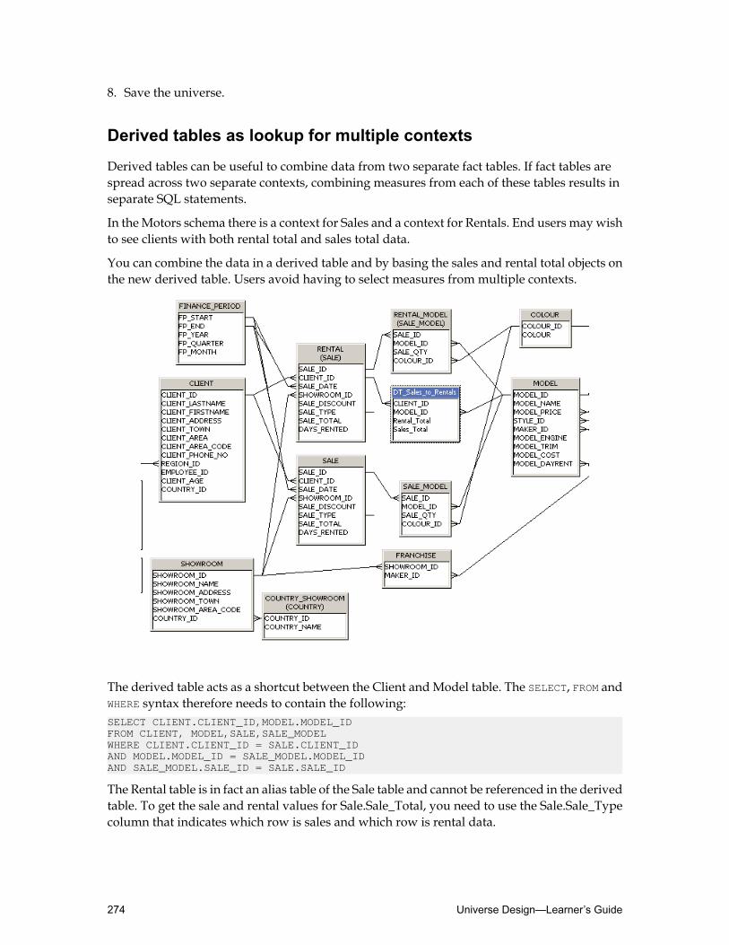
8. Save the universe.
Derived tables as lookup for multiple contexts
Derived tables can be useful to combine data from two separate fact tables. If fact tables arespread across two separate contexts, combining measures from each of these tables results inseparate SQL statements.
In theMotors schema there is a context for Sales and a context for Rentals. End users maywishto see clients with both rental total and sales total data.
You can combine the data in a derived table and by basing the sales and rental total objects onthe new derived table. Users avoid having to select measures from multiple contexts.
The derived table acts as a shortcut between the Client andModel table. The SELECT, FROM andWHERE syntax therefore needs to contain the following:SELECT CLIENT.CLIENT_ID,MODEL.MODEL_IDFROM CLIENT, MODEL,SALE,SALE_MODELWHERE CLIENT.CLIENT_ID = SALE.CLIENT_IDAND MODEL.MODEL_ID = SALE_MODEL.MODEL_IDAND SALE_MODEL.SALE_ID = SALE.SALE_ID
The Rental table is in fact an alias table of the Sale table and cannot be referenced in the derivedtable. To get the sale and rental values for Sale.Sale_Total, you need to use the Sale.Sale_Typecolumn that indicates which row is sales and which row is rental data.
Universe Design—Learner’s Guide274

The derived table SQL Syntax becomes:SELECT CLIENT.CLIENT_ID, MODEL.MODEL_ID,(SELECT CASE SALE.SALE_TYPE WHEN 'R' THENSALE.SALE_TOTAL ELSE 0 END) AS Rental_Total,(SELECT CASE SALE.SALE_TYPE WHEN 'S' THENSALE.SALE_TOTAL ELSE 0 END) AS Sales_TotalFROM CLIENT, MODEL,SALE,SALE_MODELWHERE CLIENT.CLIENT_ID = SALE.CLIENT_IDAND MODEL.MODEL_ID = SALE_MODEL.MODEL_IDAND SALE_MODEL.SALE_ID = SALE.SALE_ID
The data for sales and rentals have been combined into a derived table. After joining the tableas shown in the diagram and creating a new context, and new objects, users can run a newreport in Web Intelligence Rich Client using the Client Name object from the Client table,togetherwith the Sales Total andRental Total objects from the derived table. The data is returnedas one SQL statement and displays in one table.
When a query returns a joined SQL statement, the rows where there is no equivalent data arereturned as empty cells. These cells cannot be filtered on, as technically, they do not exist. Usingthe derived table method, the cells where there is no data returns a value of zero. This meansthat a quick filter can be used.
Allowing the user to return the clients that have both rental and sales values in a single SQLstatement.
Note: If you use derived tables to create different aggregation levels, be careful to consider theimpact on joins, contexts, and many-to-many relationships.
275Creating Derived Tables and Indexes—Learner’s Guide

Nested derived tables
Universe Designer allows designers to build nested derived tables.
Sometimes the definition of derived tables can become very complex, and complex derivedtables may generate ineffective SQL.
The nested derived table feature simply means that you can include an existing derived tablein the definition of another new derived table. This makes it easier for designers to define theSQL. The query execution is more efficient because the SQL statements are combined and sentto the database as a single statement.
With this feature, designers are able to create a single derived table and use it multiple timesin other tables as a nested derived table.
The behavior of a nested derived table is exactly the same as a simple derived table. Technically,there is no limit to the number of derived tables that can be nested, but only 20 levels aresupported.
The nested derived table feature is particularly useful if you want to use a very complex SQLstatement more than once in a universe. It allows you to reuse existing definitions. It can alsobe useful if you want to improve the performance of an existing derived table, for example byusing a filter.
Creating nested derived tables
In addition to defining derived tables, theDerived Table Editor in Universe Designer allowsyou create nested derived tables from existing derived tables, and the following functionalityis available:• TheCheck Integrity tool detects impacts on derived tables when a referenced derived table
is removed.• The Check Integrity tool checks for circular references.• TheCheck Integrity tool checks for @DerivedTable()within object definitions (SELECT and
WHERE ), which are not allowed.• The new function @DerivedTable(Derived_table_name) is added to the functions catalog
to ease building the SQL definition and is available in theDerived Table Editor.• A new function displays the existing derived tables in a new list in order to select derived
tables you want to use in the current edited definition. This new list is only displayed whenderived tables exist in the universe.
To create a nested derived table
You create a nested derived table in the same way that you create a derived table. You can addand rename a nested derived table in the same way you add and rename a derived table.1. Open your universe in Universe Designer.
2. Right-click in the universe Structure pane and selectDerived Table in the context menu.
Universe Design—Learner’s Guide276

TheDerived Tables editor opens and the center pane at the bottom of theDerived Tableseditor lists the available derived tables.
3. Type the name of your nested derived table.
4. Add the required SQL syntax for the nested derived table using one of the followingmethods:
• Type the SQL expression. You can type the entire text or use the editor assistants.• Double-click on the objects (tables, derived tables, columns, functions). When clicking
on an existing derived table name, the @DerivedTable function is inserted automatically.• Use the @DerivedTable function with the syntax: @DerivedTable(Derived_table_name)
to choose a derived table.
5. Click Check Syntax to check the syntax of your derived table and correct any potentialerrors, then validate your nested derived table.The nested derived table is added to the universe.
6. ClickOK to validate your nested derived table.The nested derived table appears in the universe Structure pane. Derived tables and nestedderived tables are lighter in color than tables that represent actual database tables.
Note: To display the table values, right-click the different tables.
277Creating Derived Tables and Indexes—Learner’s Guide

Activity: Adding derived tables
Objectives
• Create a derived table that shows the number of transactions per customer.• Create a nested derived table.
Instructions
1. Using your Motors universe, insert a derived table to show the number of transactions percustomer.
2. Name the newly derived tableDT_Best_Cust.
3. Create the SQL statement so that it looks like this:SELECT CLIENT.CLIENT_ID, COUNT(SALE.SALE_ID) AS Number_of_transactionsFROM CLIENT, SALEWHERE CLIENT.CLIENT_ID=SALE.CLIENT_IDGROUP BY CLIENT.CLIENT_ID
4. Use Check Syntax to verify your SQL statement syntax.
5. Insert a join between theDT_Best_Cust and CLIENT tables (1:1).
6. Every join (except shortcut joins) must exist in at least one context. Add the new join to theSales and to the Rentals contexts.The join between the DT_Best_Cust and CLIENT tables is from the Client_ID primary keyin the CLIENT table to the Client_ID foreign key in theDT_Best_Cust table.The table schema looks similar to this.
7. Add theNumber of Transactions object to the Client class. Define the object as a measureobject, and ensure the Associate a List of Values option is cleared.
8. In Universe Designer build a nested derived table, calledDT_Nested, using the followingsyntax:SELECT DT_Best_Cust.CLIENT_ID,CLIENT.CLIENT_LASTNAME,sum(DT_Best_Cust.Number_of_transactions)as Total_TransactionsFROM @DerivedTable(DT_Best_Cust),CLIENT WHERE DT_Best_Cust.CLIENT_ID=CLIENT.CLIENT_IDGROUP BY DT_Best_Cust.CLIENT_ID,CLIENT.CLIENT_LASTNAME
9. Join theDT_Nested to theDT_Best_Cust table (1:1).
Universe Design—Learner’s Guide278

Tip: Every join (except shortcut joins) must exist in at least one context.
10.Add theTotal_Transactions object to theClient class. Define the object as ameasure object,and ensure the Associate a List of Values option is cleared.
11.Save your universe locally.
12.In Web Intelligence Rich Client, build:• A report that shows the number of transactions per customer and the number of
transactions per country.• A report that shows the total transactions and sales revenue, per customer and per
country.
279Creating Derived Tables and Indexes—Learner’s Guide

Applying index awarenessThis unit describes how to set up a universe in Universe Designer to take advantage of primaryand foreign keys that may already exist in the data source.
After completing this unit, you will be able to:
• Understand index awareness• Set up primary key index awareness
What is index awareness?
Index awareness is the ability to take advantage of the indexes on key columns to speed dataretrieval.
The objects that you create in the universe are based on database columns that are meaningfulto an end user. For example, a Customer object retrieves the field that contains the customername. In this situation the customer table typically has a primary key (for example, an integer)that is not meaningful to the end user, but which is very important for database performance.
In Universe Designer you can apply primary and foreign key index awareness:• Primary key index awareness: by applying primary key index awareness on an object
Universe Designer can substitute the object's column value with the associated index value.The generated query uses the key value instead of the actual column value.
• Foreign key index awareness: by applying foreign key index awareness on an objectUniverseDesigner can restrict the values returned without the need to join the tables. If you build aquery that involves filtering on a value in a dimension table, Universe Designer can applythe filter directly on the fact table by using the dimension table foreign key. This eliminatesunnecessary and costly joins to dimension tables.
When you set up index awareness in Universe Designer, you tell Universe Designer whichdatabase columns are primary and foreign keys. This can have a dramatic effect on queryperformance in the following ways:• UniverseDesigner can take advantage of the indexes on key columns to speed data retrieval.
• Universe Designer can generate SQL that filters in themost efficient way. This is particularlyimportant in a star schema database. If you build a query that involves filtering on a valuein a dimension table, Universe Designer can apply the filter directly on the fact table byusing the dimension table foreign key. This eliminates unnecessary and costly joins todimension tables.
Universe Designer does not ignore duplicates with index awareness. If two customers havethe same name, Universe Designer retrieves only one unless it is aware that each customer hasa separate primary key.
Setting up index awareness
Report designers in your organization want to build a report that returns the highest pricedvalue retail price by maker, manufactured in the United Kingdom or the United States.
Universe Design—Learner’s Guide280

To build this report in Web Intelligence Rich Client, you would drag the Maker and HighestPriced Value objects into the Result Objects pane in the Report Panel. Then, drag the MakerCountry object into theQuery Filters pane and restrict the countries to the United Kingdomand the United States.
Without index awareness, Universe Designer generates the following SQL:SELECTMAKER.MAKER_NAME,max(MODEL.MODEL_PRICE)FROMMAKER,MODEL,COUNTRY COUNTRY_MAKERWHERE (MODEL.MAKER_ID=MAKER.MAKER_ID)AND (MAKER.COUNTRY_ID=COUNTRY_MAKER.COUNTRY_ID)AND COUNTRY_MAKER.COUNTRY_NAME In ( 'United Kingdom','USA' )GROUP BYMAKER.MAKER_NAME
In this case, Universe Designer has created a join to theMaker Country table in order to restrictthe countries retrieved.
With index awareness, you can tell Universe Designer that Country_ID is the primary key ofthe Country_Maker table and that it also appears in the Maker table as a foreign key. Usingthis information, Universe Designer can restrict the countries without joining to theCountry_Maker table.
In this case, Universe Designer is able to generate SQL that restricts the countries simply byfiltering the values of the Country_ID foreign key.
After setting up index awareness forMaker Country, UniverseDesigner generates the followingSQL, where “44” is the United Kingdom Country_ID value and “1” is the USA Country_IDvalue:SELECTMAKER.MAKER_NAME,max(MODEL.MODEL_PRICE)FROMMAKER,MODELWHERE (MODEL.MAKER_ID=MAKER.MAKER_ID)AND MAKER.COUNTRY_ID In ( 44,1 )GROUP BYMAKER.MAKER_NAME
What happens behind the scenes
When applying index awareness on the Maker Country, by identifying the primary key in thedata source, Business Objects is prompted to add an alternative SQL statement in the WHEREclause whenever Maker Country is used as a condition in a query.
Instead of using the County_Name field from Country_Maker table, it will now use theCountry_ID field from the Country_Maker table. This is determined from the key entriesmadein the object properties.
Index awareness allows universe designers to automatically redirect a WHERE clause conditionto another column that is known to provide better performance at query time. The index
281Creating Derived Tables and Indexes—Learner’s Guide

awareness option can be used to determine which column to choose as an alternative basedon database schema knowledge and the RDBMS optimizer.
The LOV values that end users select actually tell Business Objects what primary key valuesto substitute in final query SQL. The Keys tab tells Business Objects which SQL syntax tosubstitute in the final query SQL.
To set up primary key index awareness
1. There are two ways to set up primary key index awareness:• Right-click the object on which you want to set up index awareness and selectObject
Properties from the shortcut menu.• Select the object and clickObject Properties on the Editmenu.
The Edit Properties Of dialog box displays.
2. Click the Keys tab.
3. Click Insert.
A key line is inserted in the list of keys field.
4. To define key awareness for the primary key:• Click the drop-down arrow next to Primary Key and select Primary in the Key Type list.
Universe Design—Learner’s Guide282

• Click within the line under Select field, and then click the ... button that appears, to openthe SQL editing dialog box.
• The Edit Select Statement dialog box appears.• In the Edit Select Statement dialog box, use the SQL Editor to build the primary key
SQL SELECT clause or type it directly.
5. Select Enable.
6. ClickOK.
7. Save the universe.
Using an index awareness WHERE clause
Using a WHERE clause condition in the indexed key index acts as a data restriction. This may beuseful if there is a large amount of data returned for a particular object.
To add an index awareness WHERE clause
1. Double-click the object on which you are setting up index awareness and select the Keystab.
2. Double-click the Where clause field for the added key type.
3. Type in the required WHERE clause syntax.
4. ClickOK to apply the changes.
5. Save the universe.
Activity: Setting up index awareness
Objective
• Apply index awareness to improve the performance of SQL generation inWeb IntelligenceRich Client.
Instructions
1. Using the Client Country object in your Motors universe, enter the following under Keys:
COUNTRY_REGION.COUNTRY_IDPrimary key
COUNTRY_REGION.COUNTRY_ID = CLIENT.COUNTRY_IDWHERE
2. Save your universe locally.
283Creating Derived Tables and Indexes—Learner’s Guide

3. Create a query in Web Intelligence Rich Client with Client Country and Client Name.
4. Apply a query filter, and use the Value(s) from list option to restrict the data to a singlecountry, such as the United States.
5. View the SQL.Notice that theWHERE clause no longer uses theCOUNTRY_REGION.COUNTRY_NAME= USA statement (or whichever country you specified). It uses CLIENT.COUNTRY_ID =1.
Universe Design—Learner’s Guide284

Quiz: Derived tables and indexes1. What part of the SQL expression does Universe Designer use to create column names in the
derived table?
2. When you insert a derived table and insert joins, what happens if you do not add the newjoin to the appropriate context?
3. How do you apply index awareness on a universe object?
4. How can index awareness improve query performance?
285Creating Derived Tables and Indexes—Learner’s Guide

Lesson summaryAfter completing this lesson, you are now able to:
• Use derived tables• Apply index awareness
Universe Design—Learner’s Guide286

Lesson 13Linking Universes
Lesson introductionUsing Universe Designer, you can choose to link universes so that they share commoncomponents such as parameters, classes, objects, or joins.
After completing this lesson, you will be able to:
• Understand linked universes• Create links between universes
287Linking Universes—Learner’s Guide

Understanding linked universesUsing BusinessObjects Universe Designer, you can dynamically link the structure of one ormore universes. This can reduce development and maintenance time. When you modify acomponent in the core universe, Universe Designer propagates the change to the samecomponent in all the derived universes.
After completing this unit, you will be able to:
• Understand what linked universes are and why you would choose to use them• Understand the advantages and limitations of using linking
What are linked universes?
Linked universes are universes that share common components such as parameters, classes,objects, or joins. When you link two universes, one universe has the role of a source or coreuniverse, the other a derived universe. When changes are made in the core universe, they areautomatically propagated to the derived universes.
The linked objects can only be used to infer SQL against the database that the universe isconnected to.
For example, within a universe (B) it is possible to dynamically link to another universe (A),as shown in the diagram.
This has the effect of making it appear as though the classes, objects, and structure of universeA are part of universe B. However, they are just a lookup (signified by the fact that they aregrayed out) to universe A and cannot be edited in universe B.
Because the linked objects infer SQL against the same database defined in the connection forthe derived universe, it is not possible to use this functionality to make a universe query morethan one database.
Using linked universes
Linked universes enable you to create a set of objects and structure in a single .unv (known asthe core universe) and reuse them in another universe (known as the derived universe). Because
Universe Design—Learner’s Guide288

the core universe is dynamically linked and not copied into the derived universe, there is onlyone set of code to maintain for the duplicated objects and structure. If you make a change inthe core universe, the changes are automatically reflected in the derived universe.
Possible linking strategies
In practice, there are a number of situations where linking can be useful. You can choose touse linking for any of the following reasons:• If you decide on a strategy for creating several different universes to front end the target
database for different functions within your organization and certain objects are commonto all, this offers a way of creating the objects once only and maintaining one instance ofthem (core approach).
• If you need to create the same universe twice with different universe IDs or connections(master approach).
289Linking Universes—Learner’s Guide
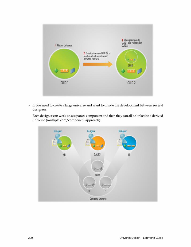
• If you need to create a large universe and want to divide the development between severaldesigners.
Each designer canwork on a separate component and then they can all be linked to a deriveduniverse (multiple core/component approach).
Universe Design—Learner’s Guide290

Advantages and limitations to linking
The following sections outline the advantages and disadvantages to linking a universe.
Key advantages
The key advantages of linking universes are:• Reduced development and maintenance time.
The universe objects and structure are created only once, and only one instance of an objectneeds to be maintained. The derived universe(s) is automatically updated when the linkeduniverse is changed.
• You can centralize often used components in a core universe, and then include them in allnew universes.
You do not have to recreate common components each time you create a new universe.
• Facilitated specialization.
Development can be split between database administratorswho set up a basic core universeand the more specialized designers who create more functional universes based on theirspecific field.
Limitations
You can link the active universe to a core universe, only if the following requirements are met:• The linked universes must use the same connection and connect to the same data source.• In a production environment, the core and derived universesmust be in the same repository.• The core universe needs to have been exported before the derived universe.
Restrictions
You need to be aware of the following restrictions when linking universes:• You can use only one level of linking. You cannot create derived universes from a universe
that is itself derived.• All classes and objects are unique in both the core universe and the derived universes. If
they are not, then naming conflicts occur and Universe Designer renames objects from thesource universe.
• The two universe structures must be joined to avoid Cartesian products resulting fromend-user queries containing objects from both structures.
• Only the table schema, classes, and objects of the core universe are available in the deriveduniverse. This means that the contexts have to be detected again in the derived universe. Insome instances, this can be an advantage because the structure of the two universes iseffectively merged in the derived universe and the old contexts are incomplete.
• LOVs associated with a core universe are not saved when you export a derived universewith the core universe structures.
• If there are two tables in the linked universeswith a common name, the table being importedis the table that is used, therefore no aliases are created. All joins will be placed on the newtable, assuming it is coming from the same database.
291Linking Universes—Learner’s Guide
Creating links between universesThere are two methods you can use to link universes. Each are used for different purposes:• Linking universes
When you link universes, you create a set of objects and structure in a single core universeand you reuse them in a derived universe.
• Including one universe within another
When you include universes, you use linking to copy the contents of the core universe intothe derived one, but then you use the Include option to break the link between the twouniverses.
Strategies for using both these methods are discussed in this unit.
After completing this unit, you will be able to:
• Link universes• Include one universe within another• Understand the advantages of each method
Linking universes
When you link an active universe to another universe, the active universe becomes the deriveduniverse, and the linkeduniverse becomes the core universe. Components from the core universeare inherited by the derived universe.
A core universe has to be exported to the Central Management System (CMS), before you canlink it in any derived table. If the core universe has not been exported, it does not appear inthe list of available universes in the Universe Parameters ➤ Links tab.
In order to link universes, the derived universe (the universe for which you want to receivethe duplicated objects and structure), has to be open in Universe Designer. Using the Linkfeature, you select the core universe file. When the link is established the contents of the coreuniverse are added to the open derived universe file.
To create a linked universe
1. In Universe Designer, open the universe file that you want to become the core universe.This is the universe that is linked into the derived universe. Components from the coreuniverse are inherited by the derived universe.
2. Select File ➤ Export to export the core universe.A core universe has to be exported to the Central Management System (CMS), before youcan link it in any derived table.
3. Browse to the location to where the core universe needs to be exported and clickOK twiceto export and exit the Export Universe dialog box.
Universe Design—Learner’s Guide292

4. In Universe Designer, open the universe file that you want to become the derived universe.
5. Access the Parametersmenu using one of the following methods:• Click the Parameters toolbar button.• Select File ➤ Parameters from the menu bar.
6. Click the Links tab.
7. Click Add Link.The Universe to Link dialog box opens. It points to the default universe location, (forexample: C:\Documents and Settings\<user_name>\Application Data\BusinessObjects\Business Objects 12.0\Universes\@<server_name>\).
8. Select the core universe you want to link.
9. ClickOpen.
The Links tab of the Universe Parameters dialog box appears.
10.ClickOK.The two universes are now linked. The tables and joins in the structure and the classes andobjects of the linked universe are grayed out, thus indicating that they reside in the sourceuniverse and cannot be edited in the derived universe.
11.Set the joins between the two structures to avoid potential Cartesian products.
12.Remove existing contexts.
13.Detect aliases.
14.Detect contexts and customize them, if required.
15.Hide/create new objects as required.
293Linking Universes—Learner’s Guide

16.If you are using aggregate awareness, be sure to specify whether the objects pointing to thenew tables are compatible with existing summary tables.
17.Save the changes in your universe and export the linked universe to the CentralManagementSystem (CMS).
Including one universe within another
In some cases, it would be better to include the component universes in the final deriveduniverse, rather than link them. Linking would mean that there are several separate universesto maintain, but the Include option copies the contents of the component universes into thederived one.
You can choose to use the Include option instead of linking when you simply want to copy allthe classes, objects and structure from one universe to another. You could do this first by linkingfrom universe B to A and then using Include to sever the link, thus making the classes, objectsand structure of the universe A part of universe B. In effect, Include is away of quickly copyingeverything in one universe to another.
To include a universe
The procedure for including is the same as for linking except that after selecting the universeto link, and before confirming the selection in the Links tab, you perform these steps instead:1. In the Links tab of theUniverse Parameters dialog box, click the universe name in theName
field.The Include button becomes active.
Universe Design—Learner’s Guide294

2. Click Include.The core universe content is copied into the derived universe as shown.
When to link and when to include?
When you include, the link to the core universe is broken and the structure, classes, and objectsof the included universe become part of the derived universe. Note that the structure, classes,and objects of the included universe are not grayed out. This indicates that they can be edited.
295Linking Universes—Learner’s Guide

Advantages of linking
• The structure is only created once in a core universe and then reused in derived universes.
• Classes and objects are only created once in a core universe and then reused in deriveduniverses.
• Most maintenance only has to be applied to the core universe.
• Derived universes are automatically updated when the core universe is amended.
Disadvantages of linking
• Only applicable for repository-based universes.
• Contexts have to be redefined in each derived universe.
• Exported lists of values are not available in each derived universe.
• The connection parameters have to be similar. For example, it is not possible to use thistechnique to query more than one database.
• Only one level of linking is allowed.
Advantages of including
• It is a quick way of copying one universe into another/others.
• Maintaining one universe rather than a number of smaller universes is simpler.
Disadvantages of including
• It is only applicable for repository-based universes.
• Contexts have to be redefined in the new universe
• If the initial universe changes, the universe does not reflect those changes.
Activity: Linking universes
Objective
• Link and then include universes
Instructions
Business requirement: Prestige Motors management wants to report on the sales performanceof its sales staff and their managers.
Use your Motors and Staff universes for this activity.1. Export your Staff universe to the Central Management System. Go to File ➤ Export and
browse to the location specified by the instructor.
2. Open your Motors universe in Universe Designer. This is your derived universe.
3. Make room in the upper left corner of the Structure pane in the Motors universe.
Universe Design—Learner’s Guide296

To do this, click in any white space in the Structure pane, click Select All from the Editmenu and then drag the tables to the right of the pane.
4. Link the structure and objects of your Staff universe in your Motors universe.
5. Place the Staff table structure in the top left-hand corner of your Motors universe structureand insert a join between the EMPLOYEE and CLIENT tables as follows:EMPLOYEE.EMP_ID = CLIENT.EMPLOYEE_ID
6. Update the contexts.Remember to ensure that context customization is reapplied, to include and exclude certainjoins in each context.
7. Save your Motors universe and close it.
8. Open your Staff universe and make the following changes to the Employee object:• Name = Sales Person• WHERE syntax =
EMPLOYEE.JOB_ID = 3
9. Save your Staff universe, export it to the same location as in step 1, and close it.
10.Open your Motors universe and check that the change in your Staff universe is reflected.
11.Change the Link to Include.
12.Save and export your Motors universe to the same location as in step1.
13.Test the results in Web Intelligence Rich Client.
Note: The exported Motors universe appears as normal text format in Web IntelligenceRich Client.
297Linking Universes—Learner’s Guide

Quiz: Linking universes1. Which of the following is an advantage of using linked universes?
○ Contexts do not have to be detected in the derived universe.○ You only have to maintain one instance of an object that is used in the linked universes.○ The exported LOV files are available in both the core and derived universes.
2. True or False. You can use linking to make a universe query more than one database.
3. True or False. When two universes are linked, if you make a change in the core universe,the changes are automatically reflected in the derived universe.
4. To copy the contents of one universe into another, would it be better to Link or to Includethe universes?
Universe Design—Learner’s Guide298

Lesson summaryAfter completing this lesson, you are now able to:
• Understand linked universes• Create links between universes
299Linking Universes—Learner’s Guide

Universe Design—Learner’s Guide300

Lesson 14Applying Universe Access Restrictions
Lesson introductionIn this lesson, you learn how to create restriction sets in order to apply security on universes.
In this lesson, you will be able to:
• Set access restrictions on a universe
301Applying Universe Access Restrictions—Learner’s Guide

Setting access restrictions on a universeOne of themost important tasks inmanaging a universe is applying security in order to restrictthe users or groups of users who are authorized to use universe objects or resources. This isdone so the data displayed in a report only applies to the person viewing the report.
For example, data can be restricted so that each salesperson is only able to view informationfor their own territory, or unit cost data on a pricing report could be hidden from all staff exceptthe accounting managers group.
After completing this unit, you will be able to:
• Describe the types of restrictions that can be applied to a universe• Describe how restriction sets are managed by Universe Designer• Apply a restriction set to a user or group of users• Create a new restriction set• Set restriction group priority• View user and group restrictions
About security and universes
In Business Objects, universe security can be managed at these levels:• Connection credentials and data source
The universe connection determines how users connect to the data source and access thedatabase. Universe designers can secure universes by setting different authentication optionsin the universe connection that corresponds back to security set at data source level.
• Central Management Server
The Business Objects system administrator can authorize or deny access to universes storedin the CMS. The administrator can define which universes users are authorized to access,and depending on the rights defined for a user group, the administrator can also restrictviewing, editing, deleting, and other actions in a universe.
• Universe
As universe designer, you can define restrictions for users who are authorized to use auniverse. A group of restrictions that correspond to a user group is called a restriction set.A restriction set can include object access, row access, query and SQL generation controls,and connection controls. This unit describes the types of restriction sets you can define ona universe.
• You can create, edit, and delete a restriction set at any time once the universe has beenexported to the CMS. You can create multiple restrictions depending on the query needs ofa target user group.
A restriction set is a named group of restrictions that apply to a universe. You can apply arestriction set to a selected group or user account for a universe. When users connect to auniverse, the objects, rows, query types, and connection that they use in the universe aredetermined by their applied restriction.
Universe Design—Learner’s Guide302

You assign a restriction set to a Business Objects user or group. This limits the access to universeobjects or resources based on the profile of the user group.
What kind of restrictions can be applied to a universe?
Access restrictions that apply to a user or group are defined in a restriction set. You can definemultiple restrictions for a universe. Restrictions can be edited, or deleted at any time.
The following types of restrictions can be included in a restriction set:
DescriptionType of restriction
The universe connection to the data source.You can select an alternative connection forthe universe.
Connection
Options to limit the size of the result set andquery execution time.Query controls
Options to control the SQL generated forqueries.SQL generation options
You can apply column-level security.Object access
You can define a WHERE clause that restrictsaccess to row and limits the result setreturned by a query.
Row access
You can replace a table referenced in theuniverse by another table in the database.Alternative table access
How are restriction sets managed?
InUniverseDesigner, youmanage restriction sets using theManageAccess Restrictionsdialogbox, which you access by selecting theManage Security option on the Toolsmenu.
303Applying Universe Access Restrictions—Learner’s Guide

TheAvailable Restrictions pane in the left-hand side of theManageAccess Restrictionsdialogbox lists all the restriction sets currently available to the universe.
The users and groups defined for each restriction set are listed in the Available Groups andUsers pane, in the right-hand side of the dialog box.
The options available for managing access restrictions on this universe are described in thetable below:
DescriptionRestriction option
To define a new restriction set.New
To modify an existing restriction set.Edit
To remove a restriction set from the list.Remove restriction set
To add a user or group from the list ofBusiness Objects users and groups definedin the Central Management Server (CMS).
Add user or group
To define a WHERE clause that restricts accessto row and limits the result set returned bya query.
Priority
To view all users and groups defined in theCMS.Preview
Universe Design—Learner’s Guide304

DescriptionRestriction option
To remove a security option from selectedusers or groups.Delete
To define whether youwant to combine rowrestrictions using the AND orOR logicaloperator.
Restriction options
You can create, edit, and delete a restriction set at any time once the universe has been exportedto the CMS. You can create multiple restrictions depending on the query needs of a target usergroup.
To create a restriction set
1. From theToolsmenu, selectManage security..., and then clickManageAccessRestrictions...
Note: If you have not yet exported the universe, a message box appears to indicate that youmust export the universe before you can create security restrictions.
2. TheManage Access Restrictions box displays.
3. In theManage Access Restrictions dialog box, clickNew.
305Applying Universe Access Restrictions—Learner’s Guide

The Edit Restriction Set dialog box displays.
The six tabs in this dialog box allow you to define the type of restriction youwant to includein this restriction set.
Caution: The Reset button at the lower left corner resets every change made in any tab. Itresets all options back to the defaults.
4. In the Restriction Name field, type the name you want to apply to the restriction.
5. Verify that the Connection tab is selected.
If youwant this restriction set to specify that certain users use a specific connection to connectto the data source, select the connection from the drop-down list or create a new one as youwould normally.
6. Click the Controls tab.
Universe Design—Learner’s Guide306

The Controls tab display.
In this tab, you can limit the size of the result set and the execution time of queries for aspecific group of users. These are the same settings that you have used before in theUniverseParameters dialog box.
7. Click the SQL tab
The SQL tab displays.
307Applying Universe Access Restrictions—Learner’s Guide

In this tab, you can set controls on the types of queries that end users can formulate for aspecific group of users. These are the same settings that you have used before in theUniverseParameters dialog box.
8. If you have completed your restriction set, clickOK to save the changes, otherwise navigatethe remaining tabs to apply further restrictions.
Note: Changes made in any of the first three tabs, display in red. This helps designers identifyand track any changes made by other designers.
Caution: The Reset button at the lower left corner resets every change made in any tab. Itresets all options back to the defaults.
To restrict access to specific universe objects
1. In the Edit Restriction dialog box, click theObjects tab.
TheObjects tab displays.
In this tab, you can specify the objects in this universe that a specific user or group of userswill not be authorized to use in queries.
2. In theObjects tab of the Edit Restriction dialog box, click Add.
Universe Design—Learner’s Guide308

TheNew Restricted Objects dialog box displays.
Note: If you are sure of the name of the object you want to restrict, you can type it in theObject Name field and clickOK to continue. Otherwise, continue to step 3.
3. Click Select.
TheObject Browser displays.
In theObject Browser, you can select the universe objects that you want to restrict for aspecific user or group of users.
4. Click the + box next to a class folder to view its contents.
The class folder opens, displaying the subfolders organized in this class. You can choose toselect the objects in these classes one by one, or you can select an entire class or subclass.All the objects in the selected class will be selected at once.
5. Select the object that you want to restrict and clickOK.
309Applying Universe Access Restrictions—Learner’s Guide

The name of the subclass and object you selected appears in theNew Restricted Objectdialog box.
6. ClickOK.
TheObjects tab of the Edit Restriction dialog box now displays the object you selected inthe list.
7. Click the Add button to continue selecting objects to restrict.
8. After all restrictions have been selected, click the Check All button to validate the objectrestriction settings.
9. The status of the objects selected appears asOK.
Universe Design—Learner’s Guide310

10.If you have completed your restriction set, clickOK to save the changes, otherwise navigatethe remaining tabs to apply further restrictions.
To restrict access to rows in the database
1. In the Edit Restriction dialog box, click the Rows tab.
The Rows tab displays.
311Applying Universe Access Restrictions—Learner’s Guide

In the Rows tab, you can define a WHERE clause on a table in the database in order to restrictaccess to specific rows, and limit the results that can be returned by queries run by specificusers or a group of users.
2. Click the Add button to create a rows restriction.
TheNew Row Restriction dialog box displays.
If you are sure of the table name and the Table andWhere Clause values, you can type themdirectly in the fields. Otherwise, continue to step 3.
3. Click the >> button to the right of the Table field.
The Table Browser displays, listing all the database tables referenced in this universe.
4. Scroll down the list and click the appropriate table.
5. ClickOK.
Universe Design—Learner’s Guide312

6. In theNewRowRestriction dialog box, click the >> button to the right of theWhere Clausefield.
TheWhere Clause Definition dialog box displays.
7. Type the appropriate WHERE clause in the text box (or build the statement using the tables,columns, operators, and functions available) to restrict the data.
8. ClickOK to close theWhere Clause Definition dialog box.
The table and WHERE clause appear in theNew Row Restriction dialog box.
9. ClickOK to close theNew Row Restriction dialog box.
10.In the Rows tab of the Edit Restriction dialog box, click the Check All button to validatethe restriction definition.
313Applying Universe Access Restrictions—Learner’s Guide

The status of the table and WHERE clause you created appears asOK.
11.If you have completed your restriction set, clickOK to save the changes, otherwise navigatethe remaining tabs to apply further restrictions.
Note: Plan and test your row restrictions very carefully. Row restrictions are only applied ifthe table is actually invoked in the SQL statement generated by the universe. With aggregateawareness, for example, the resultant SELECT clause of an object might not include the tablewith the restricted column.
To map one table to another
1. In the Edit Restriction dialog box, click the Table Mapping tab.
Universe Design—Learner’s Guide314

The Table Mapping tab displays.
In this tab, you can define the replacement of a table referenced by an object in the universeby another table for a specific user or group of users.
2. Click Add in the Table Mapping tab.
3. TheNew Table Mapping dialog box appears.
If you know the exact names of the tables, you can type them in the text boxes. Otherwise,use the Select button to select the original and replacement tables. When you have selectedthe tables, click the Check All button to validate the status of the mapping settings.
4. If you have completed your restriction set, clickOK to save the changes, otherwise navigatethe remaining tabs to apply further restrictions.
Completing your restriction set settings
When you have finished defining the restrictions for the new restriction set, click theOK buttonin the Edit Restriction dialog box.
TheManage Access Restrictions dialog box appears and the restriction set you just createdappears in the list.
315Applying Universe Access Restrictions—Learner’s Guide
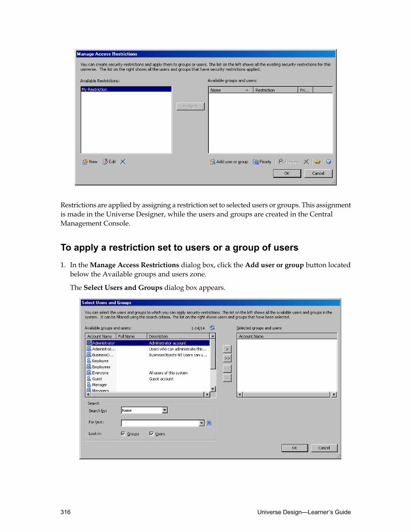
Restrictions are applied by assigning a restriction set to selected users or groups. This assignmentis made in the Universe Designer, while the users and groups are created in the CentralManagement Console.
To apply a restriction set to users or a group of users
1. In theManage Access Restrictions dialog box, click the Add user or group button locatedbelow the Available groups and users zone.
The Select Users and Groups dialog box appears.
Universe Design—Learner’s Guide316

This dialog box allows you to select the user names and groups to whom you are going toapply the restriction. You can search for names and groups by using the search functionsshown in the bottom left-hand corner of the dialog box.
2. Scroll down in theAvailable groups and users list until you see the individual user or groupyou want to restrict.
Note: Users are identified in this list with an icon representing a single individual head;groups of users are identified with two individual heads.
3. Double-click the appropriate user/group, or click the user/group and use the >> button tomove the group or user into the Selected users and groups list.
4. ClickOK to confirm and close the Select Users and Groups dialog box.
The user/group appears in the Available groups and users list in theManage AccessRestrictions dialog box.
Note: This list shows that no restriction has been assigned to this group yet. You need tonow assign a restriction to the selected user group.
5. In theManage Access Restrictions dialog box, ensure that both the appropriate user setand user group are selected.
6. Click the >>Apply button.
317Applying Universe Access Restrictions—Learner’s Guide

The restriction set now appears in the list next to the name of the individual user or usergroup.
Note: The default priority set for the restriction is 1.
7. ClickOK to close theManage Access Restrictions dialog box.
Setting restriction group priority
You can specify which restriction set to apply to a user that belongs to multiple groups, usinga universe. For example a user belongs to two groups, Sales with a restriction to view 5000rows of data, andMarketing to view 10000 rows.When the user refreshes a report, the restrictionassociated with the highest level group being applied. In the example above, if the Sales grouphad order 1 andMarketing had order 2, the restriction frommarketing (10000) would be used.
You can arrange user groups in order. The restriction for the highest group in the listed orderis used.
Note: This only applies to exclusive restrictions such as connection, table mapping, or SQLcontrols. If object restrictions are set on both groups, they are ALL applied.
To set user group priority for multiple restriction use
1. In theManageAccess Restrictionsdialog box, click a user or group in theAvailableGroupsand Users pane.
2. Click the Priority button.
Universe Design—Learner’s Guide318

The Set Group Priority box displays.
3. Select a user or group, and click theMoveUp orMoveDown buttons to change the prioritylevel.
4. ClickOK.
Viewing user and group restrictions
You can view the restrictions applied to all user and groups. In theManageAccess Restrictionsmenu, or directly from theManage securitymenu, you can select the preview option to viewall applied restrictions.
The Restriction Preview dialog box displays the settings you defined when you created therestriction set. In this example, the dialog box includes two tabs,Objects and Rows, whicheach correspond to the tabs in the Edit Restriction dialog box you used to define the restrictionsettings.
319Applying Universe Access Restrictions—Learner’s Guide

When selecting the Preview Net Access Restrictions option from the Toolsmenu, you canview the net result of combining all security restrictions for a user or a group, and all parentgroups.
To preview restrictions for a user or group
1. In theManageAccess Restrictionsdialog box, click a user or group in theAvailableGroupsand Users pane.
2. Click the Preview button.
The Restriction Preview dialog box displays.
3. Click each tab to view the settings that you defined.
4. Click Close.
5. ClickOK to close theManage Access Restrictions dialog box.
To view restrictions for all universe users and groups
1. From theToolsmenu inUniverse Designer, clickManage security...➤ PreviewNetAccessRestrictions.
The Preview Net Access Restrictions for users and groups dialog box appears.
2. Scroll down the list of groups and users and click the group or user whose restrictions youwant to view.
3. Click the Preview button.
Universe Design—Learner’s Guide320

The same Restriction Preview dialog box displays, allowing you to view the restrictionsfor the selected group.
Activity: Setting access restrictions
Objectives
• Create a new restriction set• Apply the restriction set to a user group• Test the restriction set in Web Intelligence Rich Client
Instructions
1. Youmust export the universe before you can create security restrictions. Click File➤ Export.In the Export Universemenu click Browse and select the folder to export to, as specifiedby the instructor.
2. In your Motors universe, create a restriction set called Sales_onlywith the followingrestrictions:• Set the value of Limit size of result set to to five rows.
• Restrict all objects in the staff class.
• Add a row restriction with a WHERE clause definition SHOWROOM.COUNTRY_ID = (44).
3. Apply this restriction set to the sales user. Check with the instructor for the exact user nameto use.
4. Preview the restriction to check that it is correct.
5. Save your universe and export it to the same location as in step 1.
6. Log ontoWeb Intelligence Rich Clientwith the sales user account. Checkwith the instructorfor the exact user name to use.
7. Create a new report based on your Motors universe.
8. Verify that:• Any query only returns 5 rows.• The employees objects are not visible.• No sales data for UK showrooms is returned.
321Applying Universe Access Restrictions—Learner’s Guide

Quiz: Applying universe access restrictions1. What are the six types of restrictions that can be included in a restriction set?
2. How would you restrict data to only show Clients from the USA?
Universe Design—Learner’s Guide322

Lesson summaryAfter completing this lesson, you are now able to:
• Set access restrictions on a universe
323Applying Universe Access Restrictions—Learner’s Guide

Universe Design—Learner’s Guide324

Lesson 15Managing Universes
Lesson introductionThis lesson describes how to manage universes.
In deploying, managing, and maintaining universes, you ensure that the end users in yourorganization have access to the universes they need to build reports.
After completing this lesson, you will be able to:
• Document universes• Deploy universes• Maintain universes• Deploy universes in multiple languages
325Managing Universes—Learner’s Guide
Documenting universesAs you build a universe that reflects the reporting needs of the end users in your organization,you probably want to document the progress of the universe design project.
You can use the print function in Universe Designer to document the universe as it is beingbuilt, as well as to communicate the components of the universe to other universe designersafter the project is complete.
After completing this unit, you will be able to:
• Print lists of different universe components• Print details concerning each of the universe components
Printing universe details
It is possible to print information about the universe. You can include information about theobjects, conditions, hierarchies, tables, joins, and contexts. You can also print the universeschema, showing the full graphical structure of the universe.
This feature is useful for documenting the details of the different components that make upthe universe.
There are several reasons for documenting a universe:• As universe designer, you can take snapshots of the universe at various points during its
development to chart progress against project plans.
• You can create a complete breakdown of the universe components on paper, or in PDFformat, for archiving after the design work is finished.
• Other universe designers can use this documentation to quickly familiarize themselveswiththe major components of a universe.
To select what to print
1. SelectOptions on the Toolsmenu.
2. Click the Print/PDF tab.
The Print /PDF tab displays in the Tools dialog box. This tab is divided into three zones,listing all the major components of a universe:• General zone.• List Components zone.• Full Description zone.
3. Select or clear the check dialog boxes so that the items you are interested in are printed.
Universe Design—Learner’s Guide326
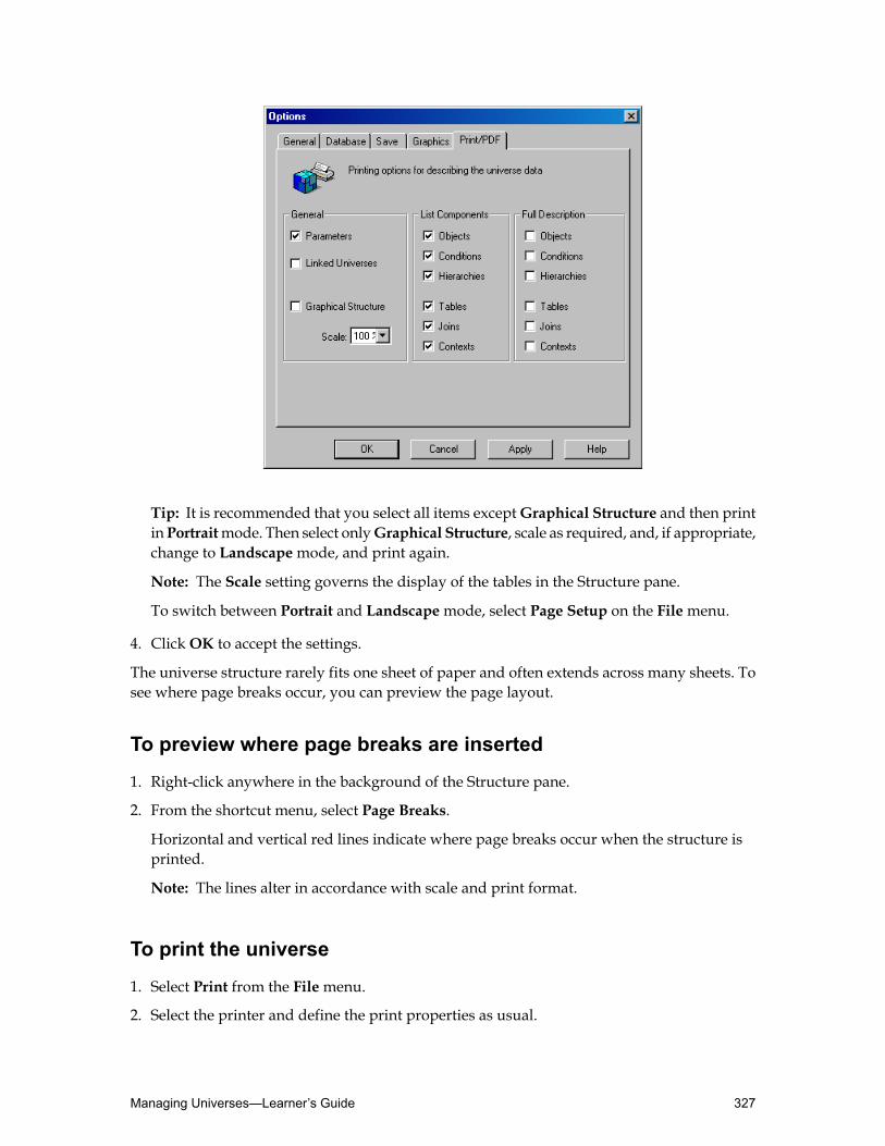
Tip: It is recommended that you select all items exceptGraphical Structure and then printinPortraitmode. Then select onlyGraphical Structure, scale as required, and, if appropriate,change to Landscapemode, and print again.
Note: The Scale setting governs the display of the tables in the Structure pane.
To switch between Portrait and Landscapemode, select Page Setup on the Filemenu.
4. ClickOK to accept the settings.
The universe structure rarely fits one sheet of paper and often extends across many sheets. Tosee where page breaks occur, you can preview the page layout.
To preview where page breaks are inserted
1. Right-click anywhere in the background of the Structure pane.
2. From the shortcut menu, select Page Breaks.
Horizontal and vertical red lines indicate where page breaks occur when the structure isprinted.
Note: The lines alter in accordance with scale and print format.
To print the universe
1. Select Print from the Filemenu.
2. Select the printer and define the print properties as usual.
327Managing Universes—Learner’s Guide

3. ClickOK to print the universe structure.
Printing options: General
The options in the left-hand side of the Print/PDF tab (Options dialog box) allow you to printoverall statistics and general information about the universe you are viewing.
Prints information and statistics about theuniverse parameters.Parameters
Prints the name of any universe to which theactive universe is linked.Linked Universes
Prints the universe schema.Graphical Structure
Sets the scale for printing the contents of theStructure pane. The scale is expressed as a
Scale percentage. By default it is 100%. Other scalevalues in the Scale List Box are 80%, 65% and50%.
Printing options: List Components
In the middle section of the Print/PDF tab, you can select the universe components that youwant to print. The names of each component are printed as a list. For example, if you chooseto print a list of the contexts in this universe, the result appears like this:
For example, if you choose to print a list of the contexts in this universe, the result appears likethis:
Universe Design—Learner’s Guide328

Printing options: Full Description
In the right-hand section of the Print/PDF tab, you can choose to print full details concerningthe different universe components.
If you select the Contexts option in both the List Components zone and the Full Descriptionzone, the details of each context are printed after the list.
329Managing Universes—Learner’s Guide

Deploying universesAfter you have completed the universe, have a small team of experts test it rigorously beforedistributing it to the end-user population.
It is recommended that the universe is tested by a small group of other designers and expertusers independently to ensure that the universe functions correctly and provides the reportsrequired with accurate results.
When you have completed the design, build, and test phases in creating a new universe, youare ready to make the universe available to end users or other report designers. This is knownas deploying the universe.
After completing this unit, you will be able to:
• Understand how universes are deployed to other users• Understand how universes are secured• Export a universe to the repository• Import a universe from the repository• Understand how version control is managed
About deploying a universe
Deploying a universe is the action of making the universe available to users or other reportdesigners. You deploy a universe by exporting it to the repository.
Only deploy a universe to end users after having completed the design, build, and test phases.
How other users access the universe
To distribute a universe to other users, either for test purposes with other Universe Designerusers, or for deployment to the end-user population, you export the universe to the repositoryand the Central Management Server (CMS).
When you export the universe, other Universe Designer users can use the File ➤ Import inUniverse Designer to open it. Teammembers can only import the universe if it has previouslybeen exported to the repository where it is stored in the CMS.
To test the universe by building reports with it, an expert user selects the universe from thelist that is available to that user.
What happens when you export a universe?
To deploy the universe for other users, you need to export it.
You can only export a universe that is defined with a secured connection. If the universe hasbeen locked in the repository by another designer, you cannot export it.
When you export a universe, three events occur:
Universe Design—Learner’s Guide330

• On your local machine, the universe .unv file is transferred to the default universe location,for example (or if it is already located there, the .unv is updated with the new version):
\\Documents and Settings\<username>\Application Data\ Business
Objects\BusinessObjects 12\universes\@<repository name>\ universe
folder\<universe>.unv
where @<repository name> is the name of the repository the universe is being exported to.
• The universe is also stored in the file system of the Input File Repository Server (FRS), as a.unw file. This is an object that contains both metadata information for the universe and thelink to the corresponding universe version stored on the repository file system.
• A new InfoObject is created in the Central Management Server (CMS). This object can bemanaged through the Central Management Control (CMC). In the CMS, a BusinessObjectsadministrator can change the universe name and description, move its location, and defineuser access rights for the universe.
Each time the universe is exported to the CMS, the universe version in the FRS is updated.This is the version that is available to BusinessObjects end users.
Note: Saving a universe is not the same as exporting a universe. Saving updates the universeon your local file system, but it does not save the CMS repository version of the universe.
Universes in the local file system
As you work on creating or updating a universe, you work on your own local file system onthemachine where Universe Designer is installed.When you save your universe, you can saveit in any folder you want.
However, after you export the universe to the repository, the universe is transferred to thedefault local location. In this example, the user "Designer1" has rights to the repository named@boetraining_6400. All universe folders for "Designer1" are under that subfolder in that user’slocal file system.
LOV files are stored in a folder with the same name as the universe file at the same level as theuniverse.
331Managing Universes—Learner’s Guide
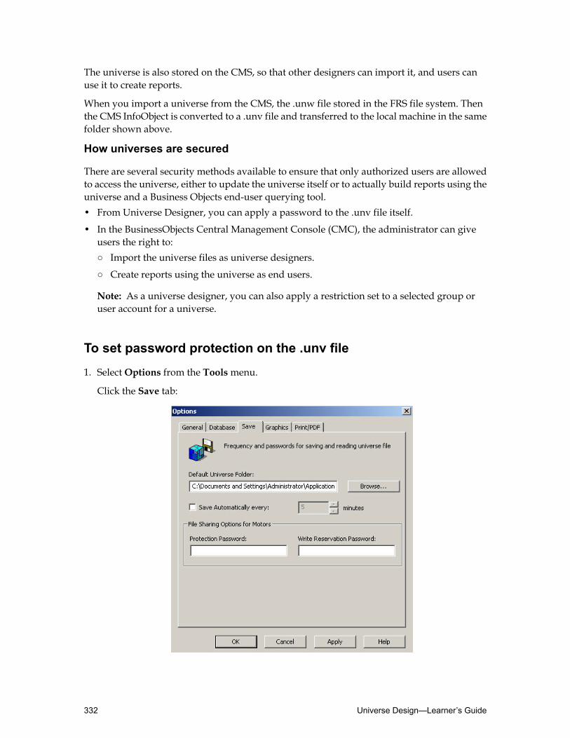
The universe is also stored on the CMS, so that other designers can import it, and users canuse it to create reports.
When you import a universe from the CMS, the .unw file stored in the FRS file system. Thenthe CMS InfoObject is converted to a .unv file and transferred to the local machine in the samefolder shown above.
How universes are secured
There are several security methods available to ensure that only authorized users are allowedto access the universe, either to update the universe itself or to actually build reports using theuniverse and a Business Objects end-user querying tool.• From Universe Designer, you can apply a password to the .unv file itself.
• In the BusinessObjects Central Management Console (CMC), the administrator can giveusers the right to:○ Import the universe files as universe designers.
○ Create reports using the universe as end users.
Note: As a universe designer, you can also apply a restriction set to a selected group oruser account for a universe.
To set password protection on the .unv file
1. SelectOptions from the Toolsmenu.
Click the Save tab:
Universe Design—Learner’s Guide332

2. Click the Protection Password field and type a password.
Users who access the universe using this password now have read-only access.
3. Click the Write Reservation Password field and type a password.
Users who access the universe using this password have read and write access. This is onlyappropriate for users who have access to Universe Designer.
4. ClickOK.
To export a universe to the repository
1. Select Export on the Filemenu.
The Export Universe dialog box appears.
2. Select a folder from theDomain drop-down list dialog box where you want to export theuniverse, or click the Browse button and select a folder in the folder browser.
3. Click a group in theGroups list dialog box.
This is the user group that is allowed to use the exported universe to create reports. Thegroups proposed in the list dialog box are the groups in which the universe designer is amember.
4. Click a universe in the Universes selection list.
The Universes selection list shows the names of the active universes.
333Managing Universes—Learner’s Guide

5. If you want to export other universes that are not open, click theAddUniverse button, andthen use the browser to select the other universes.
Note: The universes that are added would need to have a valid secured connection beforebeing able to export them.
6. ClickOK.
The universe is exported and the updated version in your local file system is synchronizedwith an updated version of the universe in the CMS.
Importing a universe
As a designer, you can import one or more universes stored in the CMS repository.
When you import a universe, the CMS checks the universe version on the repository file system.If the version is identical, the universe is made available to you if you are defined as a designerin the CMS and you have the right to access this universe.
If the universe version on the local file system is more recent than the CMS version, a messagedialog box appears asking if you want to replace the universe in the folder. If you answer Yes,then the universe on the local file system is replaced by the version in the CMS.
When you import a universe from the CMS, the .unw file store in the FRS file system and theInfoObject from the CMS are then converted to a .unv file and transferred to the default localmachine location, for example:
\\Documents and Settings\<username>\Application Data\Business Objects\BusinessObjects 12.0\universes\@<repository name>\universe folder\<universe>.unv
where @<repository name> is the name of the repository the universe is being imported from.
You can only import a universe that has already been exported to the repository.
To import a universe from the repository
1. On the Filemenu, select Import from the Filemenu.
The Import Universe dialog box appears.
Universe Design—Learner’s Guide334

2. Select a universe folder from the Folder drop-down list , or click theBrowse button to selecta universe using the folder browser.
This is the folder where the universes are exported to.
3. Click a universe name.
This is the universe that you want to import.
4. Verify the file path for the import folder in the Import Folder field.
This is the folder to where the universe is copied.
5. ClickOK.
Working with multiple designers
You can use Universe Designer in a multiple-user environment in which several designers canwork on the same universes without causing conflicts between versions.
Each time you export a universe to the repository, Universe Designer increments the revisionnumber of the universe. By looking at the universe file’s revision number, you can determinethe latest version of the universe.
When you export the universe, the repository version is always updated, even if there are noreal changes.
335Managing Universes—Learner’s Guide

If you try to export a new universe with the same name as an existing universe, UniverseDesigner displays a message asking you if you want to overwrite the existing universe.
You can also lock a universe so that only one designer at a time can make modifications on theuniverse.
After a universe has been exported to the repository, it can be shared by several designersprovided that they have the necessary user rights.
Only one designer can work on a given universe at a time. A designer who wants to work ona universe can do so only if the universe has not been locked by another designer.
To view the universe revision number
1. In Universe Designer, select Universe Parameters from the Filemenu.
2. Click the Summary tab.
The Summary tab displays. The revision number appears in the header section at the topof the tab.
To lock or unlock a universe
1. Select Import or Export on the Filemenu, depending on whether you are importing auniverse from the repository or exporting it to the repository.
The Import Universe or Export Universe dialog box displays.
2. Double-click the universe file name in the list dialog box to lock the universe before importingor exporting.
Universe Design—Learner’s Guide336

A padlock icon appears beside the universe file name to indicate that the universe has beenlocked.
3. To unlock a universe, double-click the file name again.
337Managing Universes—Learner’s Guide

Maintaining universesAfter you have completed the universe and then deployed it to the end-user population inyour organization for report creation, youmustmaintain the universe to ensure that it continuesto function correctly and provide the reports with accurate results.
After completing this unit, you will be able to:
• Understand the importance of universe maintenance• Understand how changes to the target database can impact a universe• List which changes have minimal effect on existing end-user reports and which changes
can have greater impact
Reasons for universe maintenance
There are three reasons that you may need to distribute a new version of a universe to endusers. These are:• Changes in the structure of the target database to which the universe is connected
• Change requests from end users
• Changes made by the universe designer to expand the universe or enhance the efficiencyof the inferred SQL
When introducing a newversion of a universemake your primary concern its effect on existingend-user reports that are refreshed regularly (as opposed to one-off reports). Conduct testingas rigorously as if you were distributing a completely new universe.
Treat distributing new versions of a universe as you would any software update. Distributenew versions in a controlled and regulated fashion.
Changes to the target database
Changes to the underlying database impacts end-user reports to varying degrees, accordingto the type of changes that have been made.
Greater impactMinimal Impact
Renaming/moving databaseAdding new columns
Changing existing column and table namesAdding new tables
Deleting tables and columns
The implications of these changes are:
Universe Design—Learner’s Guide338

• Additions to the target database. Adding new tables or columns to the database does notimpact the reports that are already created and refreshed regularly by end users. However,you might want to extend the universe to cover the data in these tables.
• Renaming or moving a database. To resolve this situation, you must edit the middlewaredriver.
• Changing the existing table and column names of the target database. This type of changeto a database requires some work by the universe designer, but the situation is retrievablewithout the user noticing any difference when they refresh existing reports.
In the case of a table name change, youmust reinsert the table in the structure of the universeas if you were adding a new table, and then edit all the objects that referred to the originaltable.
In the case of a column name change, you only need to edit all the objects that referred tothe original column.
In both instances, the Refresh Structure and View Associated Objects options are useful.The procedure for invoking these functions is set out below.Don’t forget theCheck Integrityoption. This is extremely useful in determining errors.
• Deleting existing tables or columns from the target database
This type of change to a database causes problems which are far more difficult for theuniverse designer to resolve. More importantly, the situation is unlikely to be retrievablewithout the user noticing any difference. Any report that contains an object that refers tothe deleted table or column produces an error when refreshed.
Where a column is deleted, you must remove all objects that relate to that column or alterthem so that they do not refer to it.
Where a table or a join column is deleted, you must also edit the structure.
Again, in both instances, the Refresh Structure, View Associated Objects options, andIntegrity Check are useful.
Detecting changes to the universe
Whenever changes to the database aremade, such as columns or tables being deleted, you needto assess the impact this has had on the universe.
Changes to the underlying target database can require you to modify the universe objects aswell.
To assess the impact of changes on the universe
1. In Universe Designer, open you universe file.
2. Select View ➤ Refresh Structure.
339Managing Universes—Learner’s Guide

Universe Designer updates the Structure pane, based on the changes made to the database.The affected tables are highlighted. Various messages can be displayed, depending on thechanges that have been made.
3. Update the universe as necessary to reflect the changes in the database structure.
To detect which objects have been affected by the changes
1. In Universe Designer, open you universe file.
2. Right-click the table header in the Structure pane of the universe window and click Viewassociated objects on the shortcut menu.
Objects that are affected by changes to the table are highlighted in the Universe pane.
3. Check the properties of each object and, if required, redefine them to reflect the changes tothe table.
Note: If a table is deleted from the database, then it is no longer possible to use this processto view the objects that are affected by the change. If possible, plan the change and view theassociated objects for a table before you delete it.
Alternatively, selectCheck Integrity on the Toolsmenu to identify the errors caused by thechanges to the structure.
Adding new tables to an existing universe
If new tables or views are added to the underlying database, you may want to add them to theuniverse as well.
As soon as new tables or views are added, they appear in the Table Browser and, you can addthem to the universe structure.
It is important that you follow the workflow illustrated below when you insert new tables inan existing universe. As an alternative to deleting and re-detecting contexts, you may want toedit the existing ones.
Adding new columns
If new columns have been added to tables in the database, Universe Designer adds themautomatically to the tables in the Structure pane when you refresh the structure.
The effect of changing objects
If the underlying database changes, the implications of the changes that you have to make onobjects in the universe and the impact of these changes on existing reports vary:
Universe Design—Learner’s Guide340

Greater impactMinimal Impact
Deleting an existing objectRedefining an object’s SQL
Changing existing column and table namesRenaming an object
Deleting and then recreating an object withthe exact same definitionCopying an object to a different class
Moving in the same class or to a differentclass
Adding new objects
When you change an object’s properties, there is little impact on the end user. For example, ifyou:• Redefine object SQL, there is no noticeable effect on the end user. When a user refreshes or
makes a query, the universe is re-imported automatically if the system detects a differencein the flags for the .unv file in the repository. As this is done in the background, it is a veryfast process and as a consequence, the users do not realize that this is occurring.
• Rename an object, this does not affect the data in existing reports when refreshed. The onlydifference end users might notice is that the column header in a tabular report changes asthis is based on the object name. This does not affect the refreshing of a report because theobject is identified by an object ID number and not its name.
• Move an object fromone class to another, it does not cause any problemswith the refreshingof existing reports. However, remember that it can have a bearing on default hierarchies.
• Copy and add objects, changing an objects’s properties has no bearing on existing reportsbecause they are new to the universe and therefore could not be part of any existing report.
The only change you can make to the objects of a universe that has a major effect on existingreports is to delete an object. When the report is refreshed an error occurs.
341Managing Universes—Learner’s Guide
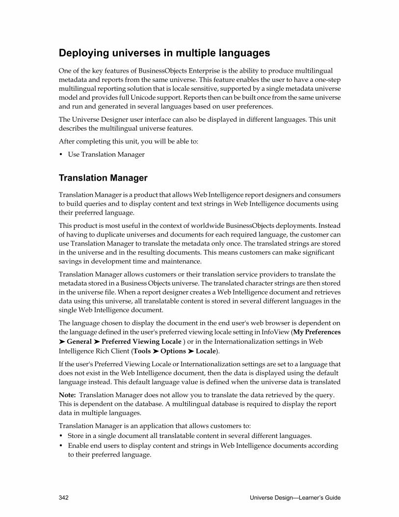
Deploying universes in multiple languagesOne of the key features of BusinessObjects Enterprise is the ability to produce multilingualmetadata and reports from the same universe. This feature enables the user to have a one-stepmultilingual reporting solution that is locale sensitive, supported by a singlemetadata universemodel andprovides full Unicode support. Reports then can be built once from the sameuniverseand run and generated in several languages based on user preferences.
The Universe Designer user interface can also be displayed in different languages. This unitdescribes the multilingual universe features.
After completing this unit, you will be able to:
• Use Translation Manager
Translation Manager
TranslationManager is a product that allowsWeb Intelligence report designers and consumersto build queries and to display content and text strings in Web Intelligence documents usingtheir preferred language.
This product is most useful in the context of worldwide BusinessObjects deployments. Insteadof having to duplicate universes and documents for each required language, the customer canuse Translation Manager to translate the metadata only once. The translated strings are storedin the universe and in the resulting documents. This means customers can make significantsavings in development time and maintenance.
Translation Manager allows customers or their translation service providers to translate themetadata stored in a Business Objects universe. The translated character strings are then storedin the universe file. When a report designer creates aWeb Intelligence document and retrievesdata using this universe, all translatable content is stored in several different languages in thesingle Web Intelligence document.
The language chosen to display the document in the end user's web browser is dependent onthe language defined in the user's preferred viewing locale setting in InfoView (MyPreferences➤ General ➤ Preferred Viewing Locale ) or in the Internationalization settings in WebIntelligence Rich Client (Tools ➤ Options ➤ Locale).
If the user's Preferred Viewing Locale or Internationalization settings are set to a language thatdoes not exist in the Web Intelligence document, then the data is displayed using the defaultlanguage instead. This default language value is defined when the universe data is translated
Note: Translation Manager does not allow you to translate the data retrieved by the query.This is dependent on the database. A multilingual database is required to display the reportdata in multiple languages.
Translation Manager is an application that allows customers to:• Store in a single document all translatable content in several different languages.• Enable end users to display content and strings in Web Intelligence documents according
to their preferred language.
Universe Design—Learner’s Guide342

Translation Manager allows you to translate the following text strings:• Class and object names.• Class and object descriptions.• Prompted query filter text.• Context names.
To translate a universe with Translation Manager
1. Launch Translation Manager from the BusinessObjects Enterprise product list located onthe Startmenu.
2. Log onto Translation Manager using the same user name and password that you use forother BusinessObjects Enterprise applications, then clickOK.
3. To translate the universemetadata, you either import the universe from the BusinessObjectsEnterprise Central Management Server (CMS), or you open a local universe copy.
• To translate a local universe copy:Click File ➤ Open.1.
2. Select the local universe copy that requires translation and clickOpen.
The local universe copy opens in the Translation Managerwindow.
• To translate a universe located in the CMS:1. Click File ➤ Import from CMS.
2. Browse to the appropriate universe folder and select the exported universe copy thatrequires translation.
3. Click Add to add the universe to the list of selected universes.
4. Click Import.
The universe is imported from the CMS and opens in the Translation Managerwindow.
4. Specify the target language for the translation. Select the appropriate language from theAvailable Languages list, and click >.The chosen language now appears in the Selected Languages pane. Also, a new columnappears in the Category View pane, where you can translate the strings into the chosenlanguage.
5. In theCategoryView pane, expand theClasses folder to view the available universe classes.Expand a class to see the objects organized in the expanded class.
6. To translate a class name, expand the appropriate class.In the Name field for the translation language add the appropriate translation string.
343Managing Universes—Learner’s Guide

7. To translate an object name, expand the appropriate object.In the Name field for the translation language add the appropriate translation string.
8. Open the Cell Properties View pane.SelectWindow ➤ Cell Properties View, or select Cell Properties View.
Universe Design—Learner’s Guide344
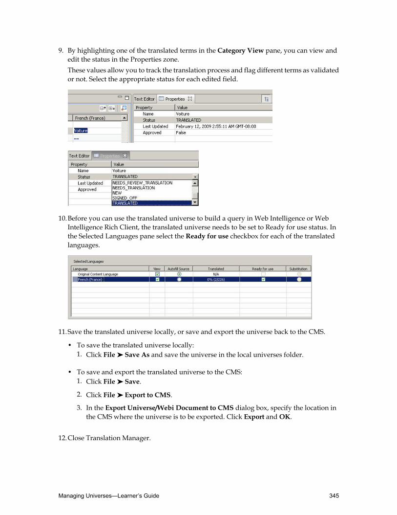
9. By highlighting one of the translated terms in the Category View pane, you can view andedit the status in the Properties zone.These values allow you to track the translation process and flag different terms as validatedor not. Select the appropriate status for each edited field.
10.Before you can use the translated universe to build a query in Web Intelligence or WebIntelligence Rich Client, the translated universe needs to be set to Ready for use status. Inthe Selected Languages pane select the Ready for use checkbox for each of the translatedlanguages.
11.Save the translated universe locally, or save and export the universe back to the CMS.
• To save the translated universe locally:Click File ➤ Save As and save the universe in the local universes folder.1.
• To save and export the translated universe to the CMS:1. Click File ➤ Save.
2. Click File ➤ Export to CMS.
3. In the Export Universe/Webi Document to CMS dialog box, specify the location inthe CMS where the universe is to be exported. Click Export andOK.
12.Close Translation Manager.
345Managing Universes—Learner’s Guide

To test a translated universe in Web Intelligence Rich Client
1. LaunchWeb Intelligence RichClient from the BusinessObjects Enterprise product list locatedin the Startmenu.
2. Enter your user account details and click Logon.
3. Click Tools ➤ Options ➤ Locale.
4. In the Internationalization settings zone, click the arrow to activate the Select formattinglocale (**) drop-down list.
5. Select the appropriate language that matches one of the languages used in the translateduniverse. ClickOK to apply the changes.
6. Select the create a new document based on a data source icon.
7. Select Browse for more data sources.
8. In theData source selectionmenu, select Universe, and clickNext.
9. Select the appropriate universe, and then clickOK.The universe displays the translated objects according to the language set in theInternationalization settings zone.
10.Build a new query using the translated objects.
Activity: Translating a universe with Translation Manager
Objective
• Use Translation Manager to translate classes and objects into French and German.
Instructions
1. In Universe Designer, import your Motors universe and save it locally.
2. Launch Translation Manager.
3. Click File ➤ Open.
Universe Design—Learner’s Guide346

4. Browse to the local copy of your Motors universe.
5. With your Motors universe open in Translation Manager, choose French (France) andGerman (Germany) as the languages and add the following values to the appropriate classand object names:
GermanFrenchObject/Class
KundeClientClient (class)
Name des KundenNom de clientClient Name
LandPaysClient Country
StadtVilleClient Town
UmsatzChiffre d'affaireSales Revenue
6. Ensure that your universe is ready for use.
7. Select File ➤ Save to save the changes to the local copy of the universe.
8. Test the translated universe results in Web Intelligence Rich Client in both French andGerman.
347Managing Universes—Learner’s Guide

Quiz: Managing universes1. Why would you decide to print details about the universe components?
2. True/False The universe file’s revision number allows you to determine if you are workingwith the latest version of the file.
3. To ensure that you are the only universe designer that can modify a universe, you can:
a. Ask your BusinessObjects administrator to restrict access to that universe.
b. Lock the universe when you export it to or import it from the repository.
c. Set restrictions on elements in the universe.
Universe Design—Learner’s Guide348

Lesson summaryAfter completing this lesson, you are now able to:
• Document universes• Deploy universes• Maintain universes• Deploy universes in multiple languages
349Managing Universes—Learner’s Guide

Universe Design—Learner’s Guide350

Appendix AEnd-of-Course Challenge
Completing the end-of-course challengeA customer has called you in to provide a Proof of Concept using a sample of their data toensure they are purchasing the correct product. Taking into account the complete product lineof BusinessObjects products, you need to identify which tools would be best for the customer,not necessarily just the ones used in this challenge, but you do not need to go into any greatdetail on additional products.
In this workshop you edit and expand your Motors universe so that:
PrestigeMotorsmanagement and personnel can run reports on number of employees, absencesand salaries by country, showroom department, job type, date and employee. Salaries shouldalso be able to be reported on by financial year, quarter, month and date.
Designing a universe is not just about using the Universe Designer module. Careful planningneeds to take place before you as a designer even think about starting up theUniverseDesignermodule. While working through the challenge, you need to consider each of the five stages inthe Universe Development Cycle process:
Preparation
Examine the database schema, maybe breaking it down into areas which cover particulardepartments to identify which tables need to be used to satisfy the HR department'srequirements.
Analysis
You require a detailed analysis of the precise information required by the users in each of thedepartments. There are a number of reports that have been identified. The focus must be onthe business language users use to describe the information they require. This can then be usedin the universe design.
Implementation phase 1: schema design
The information from the data analysis and user requirements must then be amalgamated tocreate the conceptual design of the universe, its objects and other components. Special notemust be made of any potential issues that might occur based on the design. At this stage, itwould be good to have those identified.
Implementation phase 2: building the universe in Universe Designer
The universe is created using the tools in theUniverseDesignermodule. As each part is createdit should be tested using the user module. When the universe is correct from a technical anduser point of view it can be distributed to the users.
351End-of-Course Challenge—Learner’s Guide

Maintenance
When a universe has been distributed to the users, the designer is responsible for updatingand maintaining the universe. This means keeping the universe up-to-date with any changesin user information requirements.
Your task is to work in a group and discuss the findings of some initial analysis with the HRdepartment of Prestige Motors.
• Breakout session where as a group you need to identify the requirements• Design the initial schema on paper• Present the schema to the rest of the class• Create the universe in Universe Designer• Test your universe in Web Intelligence Rich Client
Customer scenario
Prestige motors has a total of 260 employees. Of the 260 employees, there are 12 who workwithin HR, few of whom are required to create the reports, most have viewing rights only.Most of the staff can schedule reports. The management needs to see high-level reports, andnot just straightforward tables. Showroom staff may be required to generate reports.• Reports to detail the following:
Hierarchical reporting to be based on time, department, and geographic locations.1.
2. A list of absences detailing the employee, department, job title, showroom, date of absence,duration of absence, and reason for absence.
3. Employee listing by manager, by department, and when they were hired
4. A summary of the number of employees by grade and total salary amount, per showroomfor each year.
5. Salary comparison levels versus absence correlation.
6. A salary cost report broken down by financial year and country on which you can drilldown to showroom from country and quarter and month from year.
7. A summary of the salary costs and absences per showroom and per year.
• Sample of objects to provide the above:○ Employee Name○ Country (ensure the country object produces a list of countries the showrooms are in)○ Showroom○ Department○ Job Title○ Number of Employees○ Manager Name○ Salary Description○ Financial Year (for salary and absence analysis only)○ Financial Quarter (for salary and absence analysis only)
Universe Design—Learner’s Guide352
○ Financial Month (for salary and absence analysis only)○ Date of Payment (no LOV, formatted to dd/mm/yyyy)○ Salary Cost (based on the SALARIES table, formatted as currency)○ Start of Absence ( no LOV, formatted to dd/mm/yyyy)○ Duration of Absence (including weekends)○ Reason for Absence○ Absence Days (formatted with no decimal places)
Two custom hierarchies are required: one for geographic drilling, the other for time based ona financial year.
Items to watch out for:1. Multipurpose lookup tables.
2. Chasm and fan traps.
3. Additional business requirements.
Activity: Completing the end-of-course challenge - part 1
Objectives
• Conduct a breakout session where as a group you need to identify the requirements.• Design the schema on paper.• Present the schema to the rest of the class.
Instructions
1. Conduct a breakout session where as a group you need to identify the following points:• Strategy: Define the scope of the universe. Identify and review the production and
development architectures. Assemble project teams and define the initial task plan.• Analysis: Identify the ad hoc data access requirements of the user community and record
them in the form of candidate classes and objects. Identify security requirements.• Schema Design: Map objects to corporate data sources. Resolve any circular paths or
loops within the data structures that support the required objects. Plan the architecturefor the project.
• Plan the development environment: Identify resources required to support a developmentuniverse area. Identify source for development data. Verify appropriate connectivity andinitiate any changes or purchases required and plan their implementation.
• Plan the production environment: Identify resources required for a production universe.Locate source of production data. Verify connectivity. Initiate any changes or purchasesrequired and plan their implementation.
• Adopt universe standards: Have appropriate naming conventions for universe names,object definition guidelines, names for simple, complex and aggregate objects, classnames, alias tables, and help text. You may want to incorporate the class name in theobject's name. This may make object names a little long, but it makes it easier for endusers to understand where existing objects in a query come from, especially in reports
353End-of-Course Challenge—Learner’s Guide

containing many objects, some of which may have similar names. The object's nameshould always precede the class name(s). Example: Rental Date - Rental Dates - Rentals.
• Connectivity and configuration: Ensure the infrastructure is in place to supportconnectivity between users/developers and the enterprise system, including appropriatemiddleware to support the communication between clients and servers. Identify plannedconfiguration for client software. Ensure appropriate resources are available.
• Security and support: Initiate a first look at security requirements - to be refined duringsubsequent phases. Develop a support policy that is followed when the universe goesinto production. Identify necessary resources.
• Changemanagement and training: Identify procedures for the request, review, approvaland implementation of changes to the production universe. It is essential to educate evenexisting users on how to use the universe to meet the business needs.
• Identify the best practices to be followed.• Quality Assurance.
2. You need to identify the following for a high-level presentation:• Have a schema of the universe prepared on paper.• Key points to setting up your deployment:
○ Best practices.○ Strategies to adopt.○ Design workflow to follow.○ Architecture and health checks.○ Potential products to use.○ Schema of the universe based on the Customer scenario.○ Analyze recipients to determine which reporting tool to be used.
Activity: Completing the end-of-course challenge - part 2
Objectives
• Create the universe in Universe Designer.• Test your universe in Web Intelligence Rich Client.
Instructions
1. Create a new universe calledHRMotors_xx, where "xx" stands for your initials. Use yourMotorsOLEDB_xx connection to connect to the SQL Server database.
2. Using your paper design as a reference, design the universe schema. Insert tables, joins, andcreate the appropriate classes and objects.
3. Resolve any potential loops or SQL traps.
4. Check the universe integrity.
5. Test your universe in Web Intelligence Rich Client.
Universe Design—Learner’s Guide354

Appendix BUnderstandingRelational andDimensionalModeling
Understanding the metadataBefore developing a universe you must familiarize yourself with the underlying data. Whichtype of database schema is going to be used for the universe? Will this be a Data Warehousemodel, an Online Transactional Processing system (OLTP), or a Data Mart? How can you bestimplement the metadata into a universe schema to meet the end-user requirements?
355Understanding Relational and Dimensional Modeling—Learner’s Guide
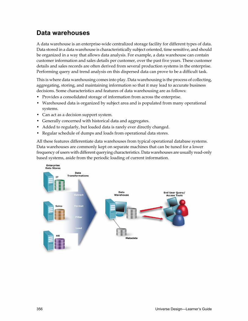
Data warehousesA data warehouse is an enterprise-wide centralized storage facility for different types of data.Data stored in a datawarehouse is characteristically subject oriented, time sensitive, and shouldbe organized in a way that allows data analysis. For example, a data warehouse can containcustomer information and sales details per customer, over the past five years. These customerdetails and sales records are often derived from several production systems in the enterprise.Performing query and trend analysis on this dispersed data can prove to be a difficult task.
This is where datawarehousing comes into play. Datawarehousing is the process of collecting,aggregating, storing, and maintaining information so that it may lead to accurate businessdecisions. Some characteristics and features of data warehousing are as follows:• Provides a consolidated storage of information from across the enterprise.• Warehoused data is organized by subject area and is populated from many operational
systems.• Can act as a decision support system.• Generally concerned with historical data and aggregates.• Added to regularly, but loaded data is rarely ever directly changed.• Regular schedule of dumps and loads from operational data stores.
All these features differentiate data warehouses from typical operational database systems.Data warehouses are commonly kept on separate machines that can be tuned for a lowerfrequency of userswith different querying characteristics.Datawarehouses are usually read-onlybased systems, aside from the periodic loading of current information.
Universe Design—Learner’s Guide356

Online Transactional Processing systemsOperational database systems dealwith handlingmany users and transactions. These databasesare often referred to as Online Transactional Processing systems (or OLTP). These operationaldatabases are continuously used systems in which users add, update, and query the storedinformation.
An example of an OLTP is a typical order-entry application. A customer calls a call center andorders products from a catalog. The sales representative answering the call can pull up theorder entry screen and enter the line items the customer desires. Whenever an order is placedit triggers inventory allocations. This seems like a relatively small process, but it will havegeneratedmany records, andmany underlying transactions. This type ofOLTP system requirestransactions to be speedy and inventory levels to be accurate. The sheer volume of these diverseoperations and the amount of data that is produced provide a poor environment for decisionsupport.
OLTP systems have been designed to support the primary business processes and are optimizedfor transaction processing. To avoid data redundancy and possible data conflicts the datamodelhas been normalized. An OLTP environment is not necessarily designed for querying andreporting, which can potentially make universe design based on an OLTP more challenging.
357Understanding Relational and Dimensional Modeling—Learner’s Guide

Data MartsA data mart is a repository of data gathered from operational data or other sources and isdesigned to serve a particular department or functional group. It is similar to aDatawarehouse,but there would be a difference in size and focus. The emphasis of a data mart is on meetingthe specific demands of a particular group of users. These users can run reports and analyzedata stored in the data mart that is designed to portray information based on their grouprequirement needs.
A common approach to using data marts is to keep data at a detail level in the data warehouseand summarize this information into the data mart for each functional group or department.
Sometimes data marts are designed for each departmental unit, and all departmental datamarts are merged later on into an enterprise-level data warehouse.
Either method offers the benefit of centralizing the information for the end users. Somecharacteristics of data marts are as follows:• Data specialized for a particular group of an organization.• Engineered for easy access.• Optimal response from lower volume queries.
Due to the more simplified and specialized nature of data marts, organizations are turning todata marts, as a quick solution to their decision-support needs.
Universe Design—Learner’s Guide358

Dimensional ModelingThe traditional entity relationship (ER) model uses a normalized approach to database design.Normalization removes redundancy from the schema to optimize storage. Data warehousingis not that concernedwith saving space. It is more concernedwithmeeting the decision supportneeds. A small amount of redundancy is usually acceptable.
Star and snowflake schemas
Dimensional modeling is a more appropriate approach to the warehouse design. Withdimensional modeling you separate the business data into logical events or facts and a set ofcorresponding dimensions.
This results in a schema that is commonly referred to as the star schema. This schema normallycontains a large and centralized fact tablewhich branches off intomany small dimension tables,resembling a star-like layout.
Fact Tables
The fact table that sits in the center of this star schema usually contains business events recordedover time. Examples of data that can be found in this table are: sales transactions, orders andreturns, bank transactions, shipments, and so forth.
The fact table normally consists of a set of numeric values and a number of foreign keys thatcorrespond to primary keys in the various dimension (lookup) tables. The information storedin the fact tables is usually static as it is historical. The most common example of a fact table inthe star schema is for sales.
Dimensions
The dimension tables consistmainly of descriptive information linked to fact records. Examplesof dimensiondata are: customer names, product descriptions, suppliers, andvendors.Dimensiontables contain fewer records than the facts table. An important factor is that the information indimension tables is not static as records in dimension tables can be updated. For example, acustomer address might be modified in the source system.
359Understanding Relational and Dimensional Modeling—Learner’s Guide

A typical datawarehouse schema always uses dimension tables or tables that dealwith periodsof time. These tables are the key element to tracking the time variant information in these typesof databases.
Sometimes a more normalized approach is taken to the dimension tables. When this happensthe star schema changes to a snowflake (or constellation) schema. A snowflake schema isbasically one fact table, connected to a number of dimension tables, and these dimension tablesin turn are connected to additional dimension tables.
In a snowflake schema it is also common to include aggregations across dimensional hierarchies,for example sales values summed up by store. These sales values can also be summarized intoseparate fact tables by region or district.
The dimensional model is a logical technique optimized for queries and reporting. It is themost common model used in current data warehousing or data mart designs. It providessimplified hierarchical paths that would enable end userswith drill-down analysis capabilities.Precalculated aggregations can be also embedded in the fact tables, which can result in rapidquery-response times.
Universe Design—Learner’s Guide360

Appendix CSQL syntaxes for other RDBMS
Alternative SQL syntaxes for other RDBMSThis appendix provides the alternative SQL syntaxes for Oracle, MySQL, DB2 and MicrosoftAccess, for the more complex objects used within this course.
ORACLE
This section provides solution syntaxes for ORACLE, based on SQL examples used in thecourse.
361SQL syntaxes for other RDBMS—Learner’s Guide
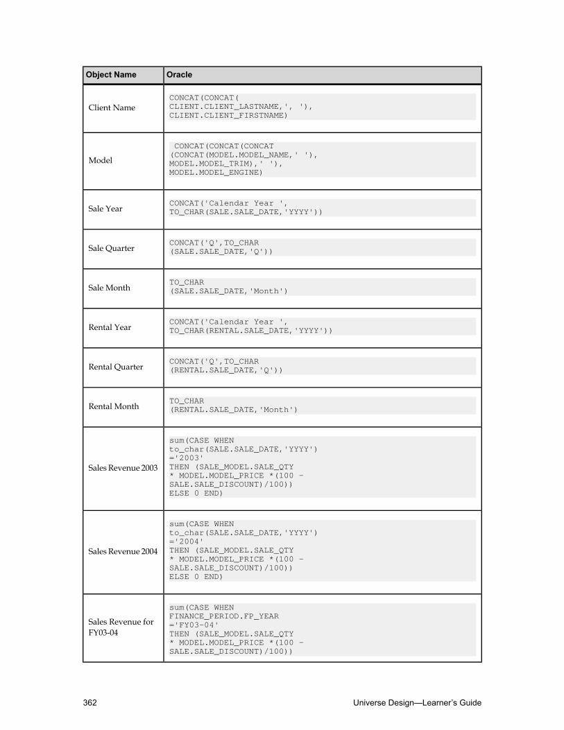
OracleObject Name
CONCAT(CONCAT(CLIENT.CLIENT_LASTNAME,', '),CLIENT.CLIENT_FIRSTNAME)
Client Name
CONCAT(CONCAT(CONCAT(CONCAT(MODEL.MODEL_NAME,' '),
Model MODEL.MODEL_TRIM),' '),MODEL.MODEL_ENGINE)
CONCAT('Calendar Year ',TO_CHAR(SALE.SALE_DATE,'YYYY'))Sale Year
CONCAT('Q',TO_CHAR(SALE.SALE_DATE,'Q'))Sale Quarter
TO_CHAR(SALE.SALE_DATE,'Month')Sale Month
CONCAT('Calendar Year ',TO_CHAR(RENTAL.SALE_DATE,'YYYY'))Rental Year
CONCAT('Q',TO_CHAR(RENTAL.SALE_DATE,'Q'))Rental Quarter
TO_CHAR(RENTAL.SALE_DATE,'Month')Rental Month
sum(CASE WHEN to_char(SALE.SALE_DATE,'YYYY')
Sales Revenue 2003='2003' THEN (SALE_MODEL.SALE_QTY * MODEL.MODEL_PRICE *(100 - SALE.SALE_DISCOUNT)/100)) ELSE 0 END)
sum(CASE WHEN to_char(SALE.SALE_DATE,'YYYY')
Sales Revenue 2004='2004' THEN (SALE_MODEL.SALE_QTY * MODEL.MODEL_PRICE *(100 - SALE.SALE_DISCOUNT)/100)) ELSE 0 END)
sum(CASE WHEN FINANCE_PERIOD.FP_YEAR
Sales Revenue forFY03-04
='FY03-04' THEN (SALE_MODEL.SALE_QTY * MODEL.MODEL_PRICE *(100 - SALE.SALE_DISCOUNT)/100))
Universe Design—Learner’s Guide362

OracleObject Name
ELSE 0 END)
sum(CASE WHEN FINANCE_PERIOD.FP_YEAR
Sales Revenue forFY04-05
='FY04-05' THEN (SALE_MODEL.SALE_QTY * MODEL.MODEL_PRICE *(100 - SALE.SALE_DISCOUNT)/100)) ELSE 0 END)
DB2
This section provides solution syntaxes for DB2, based on SQL examples used in the course.
363SQL syntaxes for other RDBMS—Learner’s Guide
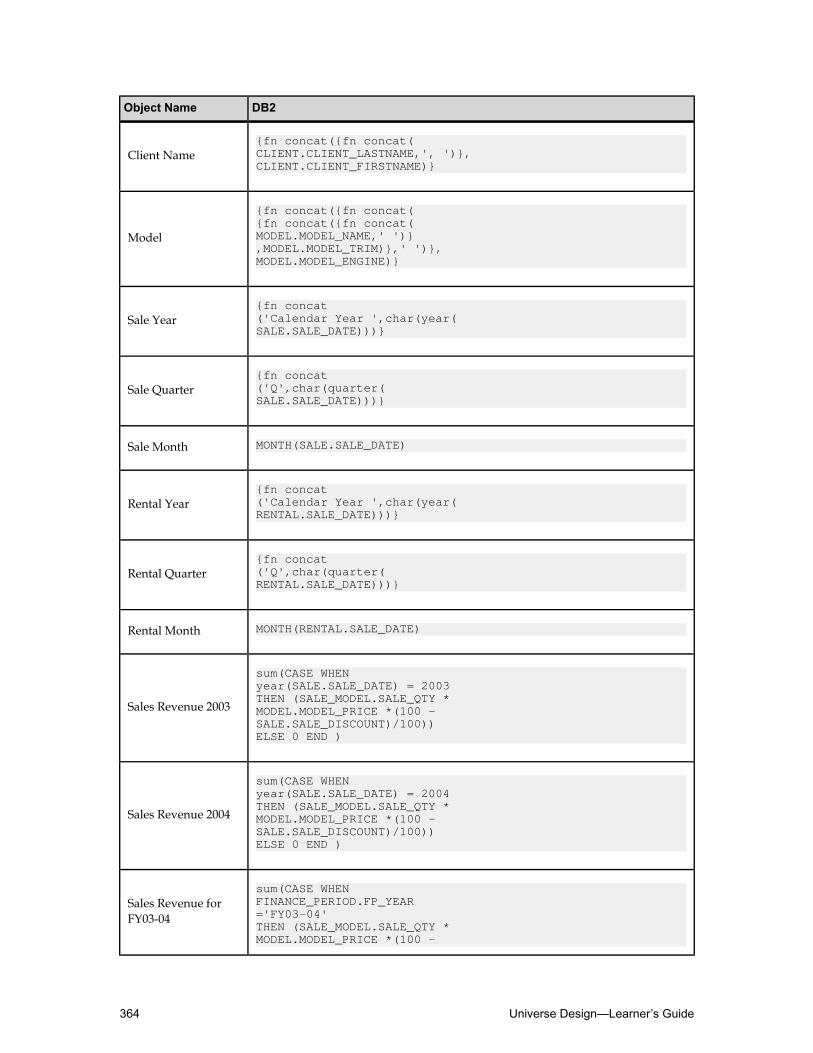
DB2Object Name
{fn concat({fn concat(CLIENT.CLIENT_LASTNAME,', ')},CLIENT.CLIENT_FIRSTNAME)}
Client Name
{fn concat({fn concat({fn concat({fn concat(
Model MODEL.MODEL_NAME,' ')},MODEL.MODEL_TRIM)},' ')},MODEL.MODEL_ENGINE)}
{fn concat('Calendar Year ',char(year(SALE.SALE_DATE)))}
Sale Year
{fn concat('Q',char(quarter(SALE.SALE_DATE)))}
Sale Quarter
MONTH(SALE.SALE_DATE)Sale Month
{fn concat('Calendar Year ',char(year(RENTAL.SALE_DATE)))}
Rental Year
{fn concat('Q',char(quarter(RENTAL.SALE_DATE)))}
Rental Quarter
MONTH(RENTAL.SALE_DATE)Rental Month
sum(CASE WHEN year(SALE.SALE_DATE) = 2003
Sales Revenue 2003THEN (SALE_MODEL.SALE_QTY * MODEL.MODEL_PRICE *(100 - SALE.SALE_DISCOUNT)/100))ELSE 0 END )
sum(CASE WHEN year(SALE.SALE_DATE) = 2004
Sales Revenue 2004THEN (SALE_MODEL.SALE_QTY * MODEL.MODEL_PRICE *(100 - SALE.SALE_DISCOUNT)/100))ELSE 0 END )
sum(CASE WHEN FINANCE_PERIOD.FP_YEARSales Revenue for
FY03-04 ='FY03-04'THEN (SALE_MODEL.SALE_QTY * MODEL.MODEL_PRICE *(100 -
Universe Design—Learner’s Guide364

DB2Object Name
SALE.SALE_DISCOUNT)/100))ELSE 0 END )
sum(CASE WHEN FINANCE_PERIOD.FP_YEAR
Sales Revenue forFY04-05
='FY04-05'THEN (SALE_MODEL.SALE_QTY * MODEL.MODEL_PRICE *(100 - SALE.SALE_DISCOUNT)/100))ELSE 0 END )
MySQL
This section provides solution syntaxes forMySQL, based on SQL examples used in the course.
365SQL syntaxes for other RDBMS—Learner’s Guide

MySQLObject Name
{fn concat({fn concat(CLIENT.CLIENT_LASTNAME,', ')},CLIENT.CLIENT_FIRSTNAME)}
Client Name
{fn concat({fn concat({fn concat({fn concat(
Model MODEL.MODEL_NAME,' ')},MODEL.MODEL_TRIM)},' ')},MODEL.MODEL_ENGINE)}
{fn concat('Calendar Year ',YEAR(SALE.SALE_DATE))}Sale Year
{fn concat('Q',QUARTER(SALE.SALE_DATE))}Sale Quarter
MONTH(SALE.SALE_DATE)Sale Month
{fn concat('Calendar Year ',YEAR(RENTAL.SALE_DATE))}Rental Year
{fn concat('Q',QUARTER(RENTAL.SALE_DATE))}Rental Quarter
MONTH(RENTAL.SALE_DATE)Rental Month
sum(CASE WHEN {fn year(SALE.SALE_DATE)}
Sales Revenue 2003= 2003 THEN (SALE_MODEL.SALE_QTY *MODEL.MODEL_PRICE * (100 - SALE.SALE_DISCOUNT)/100))ELSE 0 END)
sum(CASE WHEN {fn year(SALE.SALE_DATE)}
Sales Revenue 2004= 2004 THEN (SALE_MODEL.SALE_QTY *MODEL.MODEL_PRICE * (100 - SALE.SALE_DISCOUNT)/100))ELSE 0 END)
sum(CASE WHEN FINANCE_PERIOD.FP_YEAR
Sales Revenue forFY03-04
='FY03-04'THEN (SALE_MODEL.SALE_QTY *MODEL.MODEL_PRICE * (100 - SALE.SALE_DISCOUNT)/100))ELSE 0 END)
Universe Design—Learner’s Guide366

MySQLObject Name
Sales Revenue forFY04-05
sum(CASE WHEN FINANCE_PERIOD.FP_YEAR='FY04-05'THEN (SALE_MODEL.SALE_QTY *MODEL.MODEL_PRICE * (100 - SALE.SALE_DISCOUNT)/100))ELSE 0 END)
Microsoft Access
This section provides solution syntaxes for Microsoft Access, based on SQL examples used inthe course.
367SQL syntaxes for other RDBMS—Learner’s Guide

Microsoft AccessObject Name
CLIENT.CLIENT_LASTNAME +', '+ CLIENT.CLIENT_FIRSTNAMEClient Name
MODEL.MODEL_NAME +' '+ MODEL.MODEL_TRIM +' '+ MODEL.MODEL_ENGINEModel
'Calendar Year ' + format(SALE.SALE_DATE,'YYYY')Sale Year
'Q' + format(SALE.SALE_DATE,'Q')Sale Quarter
format(SALE.SALE_DATE,'Mmm')Sale Month
'Calendar Year ' + format(RENTAL.SALE_DATE,'YYYY')Rental Year
'Q' + format(RENTAL.SALE_DATE,'Q')Rental Quarter
format(RENTAL.SALE_DATE,'Mmm')Rental Month
sum(IIf{fn year(SALE.SALE_DATE )} = 2003,(SALE_MODEL.SALE_QTY * MODEL.MODEL_PRICE *(100-SALE.SALE_DISCOUNT)/100)),0))
Sales Revenue 2003
sum(IIf{fn year(SALE.SALE_DATE )} = 2004,(SALE_MODEL.SALE_QTY * MODEL.MODEL_PRICE *(100-SALE.SALE_DISCOUNT)/100)),0))
Sales Revenue 2004
sum(IIf(FINANCE_PERIOD.FP_YEAR ='FY03-04',(SALE_MODEL.SALE_QTY * MODEL.MODEL_PRICE *(100-SALE.SALE_DISCOUNT)/100)),0))
Sales Revenue forFY03-04
sum(IIf(FINANCE_PERIOD.FP_YEAR ='FY04-05',(SALE_MODEL.SALE_QTY * MODEL.MODEL_PRICE *(100-SALE.SALE_DISCOUNT)/100)),0))
Sales Revenue forFY04-05
Universe Design—Learner’s Guide368

Answer Key
This section contains the answers to the reviews and/or activities for the applicable lessons.
369Answer Key—Learner’s Guide

Universe Design—Learner’s Guide370

Quiz: Understanding BusinessObjects universesPage 29
1. What are the two main panes in Universe Designer?
Answer: The Universe pane, and the Structure pane.
2. What are the three ways to issue commands in Universe Designer?
Answer:Menu options, toolbar buttons, and right-click drop-down menus.
3. Where can you define what specific information about the universe gets printed?
Answer: Under Tools ➤ Options ➤ Print/PDF.
371Answer Key—Learner’s Guide

Quiz: Creating the course universePage 52
1. Information about universe administration appears on theUniverse Parametersdialog box.Under which tab can you find this information?
Answer: The Summary tab.
2. Can a universe and its content be embedded in another universe?
Answer: Yes, you can set this up in the Links tab of the Universe Parameters dialog box.Remember that both universes must reference the same database account or targeted datasource.
3. If you want to distribute the completed universe to the user population using theBusinessObjects repository, which type of connection should you use?
Answer: Use a secured connection.
Universe Design—Learner’s Guide372

Quiz: Building the universe structurePage 89
1. A schema contains two elements. What are they?
Answer:○ Tables○ Joins
2. What are three reasonswhyusing the automatic detection routine for setting join cardinalitiesis not recommended?
Answer:○ Cardinality is based on logic. The automatic detection routine uses physical cardinality,
and runs a physical count on the values in both columns being joined. You may getincorrect results if the physical count does not return the same result as a logical analysisof the data.
○ The algorithm used by the automatic detection routine assumes that you have sufficientquantity of data in both tables to be representative in ratio to the database in a liveenvironment. If you are designing against a test database, for example, with only arepresentative sampling of data, because the routine runs a physical count, it could giveyou the incorrect answer.
○ The automatic detection routine runs three subsequent queries at the target database perjoin, which may take a very long time for large databases.
3. What type of join is created by default between two tables?
Answer: The default join type is equi-join.
373Answer Key—Learner’s Guide

Quiz: Creating dimension objectsPage 116
1. Which of the three types of objects contain aggregate functions that map to statistics in thedatabase?
Answer:Measure objects.
2. When you are testing objects, what are the three things for which you need to test?
Answer:○ Do the objects exist? If not, youmay have forgotten to save your universe since the object
you are testing was created.○ Does the SQL appear correct?○ Are the results of the query correct?
3. If each object maps to a column or function in a target database, when used in a query, whatkind of statement does the object infer?
Answer: A SELECT statement.
Universe Design—Learner’s Guide374

Quiz: Creating measure objectsPage 138
1. Measure objects are very flexible because they are semantically dynamic. What does thismean?
Answer:Thismeans that the values they return in a query vary depending on the dimensionand detail objects that are used with them.
2. Measure objects are created in the same way as a dimension or detail object. However, theobject properties differ in two ways. What are they?
Answer: The object properties differ as follows:○ The Data Type field must be set to Number.○ The Select field must include an aggregate function.
375Answer Key—Learner’s Guide

Quiz: Resolving loops in a universePage 170
1. What is the first step in resolving loops?
Answer: Detecting cardinalities.
2. What causes a loop?
Answer: A loop is a join path issue that arises from the way that lookup and fact tables arerelated in a relational database. Loops can produce instances where a query returns too fewrows of data.
3. What are the two main methods of resolving loops?
Answer:○ Aliases○ Contexts
4. What are the three types of queries you can use to test your contexts?
Answer:○ Inferred○ Incompatible○ Ambiguous
Universe Design—Learner’s Guide376

Quiz: Resolving SQL trapsPage 200
1. A chasm trap can occur when:
Answer:1. Two joins from many-to-one-to-many converge on a single table.
2. The query includes objects based on the two “many” tables.
3. There are multiple rows returned for a single dimension value.
2. Describe two ways to resolve chasm traps.
Answer:1. Create a context for each fact table. This solution works in all cases.
2. Modify the SQL parameters for the universe so you can generate separate SQL queriesfor each measure. This solution only works for measure objects. It does not generateseparate queries for dimension or detail objects.
3. Describe three ways to resolve fan traps.
Answer:1. Alter the SQL parameters for the universe. This only works for measure objects. This
resolution works the same for chasm and fan traps.
2. Create an alias for the table containing the initial aggregation, and then use DetectContexts (Tools ➤ Detect Contexts) to detect and propose a context for the alias tableand a context for the original table. This is the most effective way to solve the fan trapproblem as it works with measure and dimension objects.
3. Avoid the fan trap in the first place by using the same level of granularity.
377Answer Key—Learner’s Guide

Quiz: Applying restrictions on objectsPage 215
1. What is a restriction?
Answer: A restriction is a condition in SQL that sets criteria to limit the data returned by aquery.
2. Explain two drawbacks of using restrictions at the object level.
Answer:○ Youwould get a confusing proliferation of objects for end users because youwould then
need a French Clients object, a German Clients object, and so on.○ As these objects would all represent alternate restrictions, you would not be able to
construct a logical default hierarchy (which end users make use of when drilling down).○ Although the UK Clients example is fairly clear, in many cases the restriction is not
obvious to the user simply from the name of the object. The details of theWHERE clauseare not shown in the user module.
○ If two or more similarly restricted objects are included in the same query, the conflictbetween the WHERE clauses causes no data to be returned.
3. When should you use self-restricting joins?
Answer:Use self-restricting joins to apply restrictions to tableswhen youwant the restrictionto apply irrespective of where the table is used in the SQL. This method is ideal when atable uses a flag to switch between two or more domains.
Universe Design—Learner’s Guide378
Quiz: Using @functions with objectsPage 232
1. What parameter does the @select require?
Answer: @select requires the path of the existing object to be dynamically linked to.
2. True or False. You can use the @where function in a condition object to point to an object,but not the other way around.
Answer: True
3. What function is used to create an interactive object that causes amessage to appear at queryruntime, that asks the user for specific input?
Answer:b. @prompt
4. In the @prompt two parameters are mandatory and three are optional. What parameters areoptional?
Answer:○ LOV pointer or hard-coded list○ Mono or Multi○ Free or Constrained
379Answer Key—Learner’s Guide
Quiz: Using hierarchiesPage 254
1. A _____________ hierarchy is the hierarchy based on the order of the objects within theclass.○ a) Default○ b) Custom
Answer: Default
2. What are two advantages of automatic time hierarchies?
Answer:1. It is a fairly quick and easy way to set up a time hierarchy.
2. It automatically creates an SQL Select clause using the appropriate scalar function or theRDBMS of the target database.
Universe Design—Learner’s Guide380

Quiz: Using lists of valuesPage 268
1. By default what values are contained in a list of values (LOV)?
Answer: An LOV is a list associated with an object that, by default, contains all the distinctvalues from the fields in the database for that object.
2. What are three things that a universe designer should keep inmindwhen decidingwhetherto associate an LOV with an object?
Answer:○ Because an LOV is based on a SELECT Distinct query that is sent to the target database,
associating an LOV has implications for the efficiency of Web Intelligence.○ The only purpose for creating an LOV is to assist the end user in choosing an operand
value for a condition. If the LOV does not do this, there is no point in associating it withthe object.
○ Unless the LOV is based on a personal file and not a query, the list only holds valuesthat exist within the database.
3. For what types of objects is it recommended not to provide an LOV?
Answer: It is recommended that you do not provide an LOV for the following types ofobjects:○ All measure objects.○ Any object where the LOV consists of a large number of values.○ Any object where the list on its own would be meaningless.
381Answer Key—Learner’s Guide

Quiz: Derived tables and indexesPage 285
1. What part of the SQL expression does Universe Designer use to create column names in thederived table?
Answer: It uses an alias (in SQL) to create column names.
For example:count(Region.Region_ID) as number_of_regions
2. When you insert a derived table and insert joins, what happens if you do not add the newjoin to the appropriate context?
Answer:○ When you parse the derived table’s SQL, it generates an exception.○ When you run a query, the derived table creates a Cartesian product.○ The objects you create from the derived table are incompatible with objects from any of
the existing contexts.
3. How do you apply index awareness on a universe object?
Answer: Go to the Keys tab of the Edit Properties dialog box for the object you want tomake index aware.
4. How can index awareness improve query performance?
Answer: It can improve query performance by taking advantage of indexes on key columnsin the data source.
Universe Design—Learner’s Guide382

Quiz: Linking universesPage 298
1. Which of the following is an advantage of using linked universes?○ Contexts do not have to be detected in the derived universe.○ You only have to maintain one instance of an object that is used in the linked universes.○ The exported LOV files are available in both the core and derived universes.
Answer: You only have to maintain one instance of an object that is used in the linkeduniverses.
2. True or False. You can use linking to make a universe query more than one database.
Answer: False
3. True or False. When two universes are linked, if you make a change in the core universe,the changes are automatically reflected in the derived universe.
Answer: True
4. To copy the contents of one universe into another, would it be better to Link or to Includethe universes?
Answer: Include
383Answer Key—Learner’s Guide
Quiz: Applying universe access restrictionsPage 322
1. What are the six types of restrictions that can be included in a restriction set?
Answer:○ Connections○ Query controls○ SQL generation options○ Object access○ Row access○ Alternative table access
2. How would you restrict data to only show Clients from the USA?
Answer:
Define a WHERE clause in the Rows tab with the syntax:
COUNTRY_REGION.COUNTRY_NAME = 'USA'
Universe Design—Learner’s Guide384

Quiz: Managing universesPage 348
1. Why would you decide to print details about the universe components?
Answer:○ To track progress against project plans during universe development and test phases.○ To archive after the design work is finished.○ To communicate the components of the universe to other designers.
2. True/False The universe file’s revision number allows you to determine if you are workingwith the latest version of the file.
Answer: True.
3. To ensure that you are the only universe designer that can modify a universe, you can:
Answer:b. Lock the universe when you export it to or import it from the repository.
385Answer Key—Learner’s Guide

Universe Design—Learner’s Guide386

Notes

Notes

Notes

Notes