boss rv-500 owner’s manual - · pdf fileediting a patch 9 saving a patch 10 parameter...
TRANSCRIPT

Getting Ready 2Installing the Batteries 2Connecting the Equipment 2
Basic Operation 4Adjusting the Reverb 4
Adjusting the Delay 5Turning Reverb On/Off 6Switching Banks/Patches 7Using the [TAP/CTL] Switch to Control the Reverb 8
Editing a Patch 9
Saving a Patch 10
Parameter List 11PATCH 11
Parameters Common to All Modes 11Parameters for Each Mode 12
CONTROL 16ASSIGN 16BANK 18SYSTEM 18MIDI 18MIDI PC MAP 19
Convenient Functions 20Specifying Whether to Carry-Over the Reverb Sound 20 Assigning the Functions of the [A], [B], and [TAP/CTL] Switches 20
Using Two Patches Simultaneously (Simul Mode) 21
Assigning a Function to an External Pedal 22
Synchronizing with a DAW or External MIDI Device 24
Connection Example 24MIDI Messages That Can Be Transmitted and Received 24MIDI Routing 25
Restoring the Factory Default Settings 26
Transmitting Data to an External MIDI Device 26
Troubleshooting 27
Main Specifications 27
USING THE UNIT SAFELY 28
IMPORTANT NOTES 28
Before using this unit, carefully read “USING THE UNIT SAFELY” and “IMPORTANT NOTES” (leaflet “USING THE UNIT SAFELY” and Owner’s Manual (p. 28)). After reading, keep the document(s) including those sections where it will be available for immediate reference.
5 Thanks to 32-bit high-precision processing at a 96 kHz sampling rate from input to output, the RV-500 gives you stunningly high-quality reverb.
5 With an easily readable screen and an independent [TAP/CTL] switch, it delivers both high functionality as well as ease of use during live performances.
5 A total of 12 types of reverb are provided, including classic varieties as well as “DUAL” which lets you use two reverbs simultaneously, the sparkling “SHIMMER,” and models such as “Roland SPACE ECHO RE-201” and “Roland DIGITAL REVERB SRV-2000.” Powerful DSP lets you use delay and modulation simultaneously for all reverbs.
5 The memory function lets you store and recall 297 different setups from internal memory. “CARRYOVER” provides seamless transition that preserves the reverberant sound when switching between patches.
5 By connecting the RV-500 via a USB cable or MIDI cables, you can switch sounds and control parameters in synchronization with your computer DAW or an external MIDI device.
© 2017 Roland Corporation
Owner’s Manual
2
Getting Ready
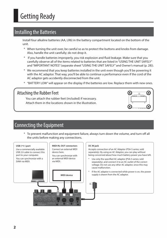
Installing the BatteriesInstall four alkaline batteries (AA, LR6) in the battery compartment located on the bottom of the unit.
* When turning the unit over, be careful so as to protect the buttons and knobs from damage. Also, handle the unit carefully; do not drop it.
* If you handle batteries improperly, you risk explosion and fluid leakage. Make sure that you carefully observe all of the items related to batteries that are listed in “USING THE UNIT SAFELY” and “IMPORTANT NOTES” (separate sheet “USING THE UNIT SAFELY” and Owner’s manual (p. 28)).
* We recommend that you keep batteries installed in the unit even though you’ll be powering it with the AC adaptor. That way, you’ll be able to continue a performance even if the cord of the AC adaptor gets accidently disconnected from the unit.
* “BATTERY LOW” will appear on the display if the batteries are low. Replace them with new ones.
Attaching the Rubber FeetYou can attach the rubber feet (included) if necessary.Attach them in the locations shown in the illustration.
Connecting the Equipment* To prevent malfunction and equipment failure, always turn down the volume, and turn off all
the units before making any connections.
DC IN jackAccepts connection of an AC Adaptor (PSA-S series; sold separately). By using an AC Adaptor, you can play without being concerned about how much battery power you have left.
* Use only the specified AC adaptor (PSA-S series; sold separately), and connect it to an AC outlet of the correct voltage. Do not use any other AC adaptor, since this may cause malfunction.
* If the AC adaptor is connected while power is on, the power supply is drawn from the AC adaptor.
USB (O) portUse a commercially available USB 2.0 cable to connect this port to your computer.You can synchronize with a DAW via MIDI.
MIDI IN, OUT connectorsConnect an external MIDI device here. You can synchronize with an external MIDI device via MIDI.
MIDI device

3
Getting Ready
CTL 1, 2/EXP jackYou can control various parameters by connecting a footswitch (FS-5U, FS-5L, FS-6, FS-7: sold separately) or an expression pedal (such as the EV-30, Roland EV-5: sold separately) to the CTL 1, 2/EXP jack (p. 22).
When connecting expression pedal
EXP
* Use only the specified expression pedal (EV-30, Roland EV-5; sold separately). By connecting any other expression pedals, you risk causing malfunction and/or damage to the unit.
When Connecting an FS-7When Connecting an FS-6
MODE/POLARITY switch
CTL 2 CTL 1
Stereo 1/4” phone type ,Stereo 1/4” phone type
MODE/POLARITY switch
When Connecting an FS-5U (or FS-5L)
When Connecting Two FS-5Us (or FS-5Ls)
1/4” phone type ,1/4” phone type
CTL 1 CTL 2 CTL 1
POLARITY switch
Stereo 1/4” phone type ,1/4” phone type x 2
When connecting an FS-5L, set MODE to “MOMENT” (p. 22).
OUTPUT A/MONO, B jacksConnect these jacks to your amp or monitor speakers.If you’re using a mono setup, use only the OUTPUT A/MONO jack.
* Do not connect headphones to the OUTPUT A/MONO, B jacks. Doing so may damage the headphones.
INPUT A/MONO, B jacksConnect your electric guitar, or another instrument or effect unit, to these jacks.
* Use the INPUT A/MONO jack and B jack when connecting a stereo-output effects unit. Use only the INPUT A/MONO jack if you’re using a mono source.
Turning the power on/offThe INPUT A/MONO jack doubles as the power switch. Power to the unit is turned on when you plug into the INPUT A/MONO jack; the power is turned off when the cable is unplugged.When powering up:Turn on the power to your amp last.When powering down:Turn off the power to your amp first.
Stereo 1/4” phone type ,Stereo 1/4” phone type

4
Basic Operation
Adjusting the Reverb
[LOW] knobAdjusts the character of the effect sound’s low-frequency range.
[TIME/VALUE] knobAdjusts the reverb time.To make larger changes in the value, turn the knob while pressing it.
[E. LEVEL] knobAdjusts the volume of the effect sound.
[I] [H] buttonsSwitch screens.
[H]
[I]
In simul mode (p. 21)
Reverb timeReverb time
Top screen
Turn the [TIME/VALUE] knob to adjust the value.
[H]
[I]
[A] [B] switchesSwitch banks/patches (p. 7).
[PRE-DELAY] knobAdjusts the time until when the reverb sound is output.
[HIGH] knobAdjusts the character of the effect sound’s high-frequency range.
[TAP/CTL] switchPress this switch to change how the reverb is applied (p. 8).
[MODE] knobSelects the type of reverb.
ROOM Reverb that simulates the reverberation in a room.
HALL Reverb that simulates the reverberation in a concert hall.
PLATE Reverb that simulates plate reverb (a reverb unit utilizing the vibration of a metal plate).
SPRING Reverb that simulates the spring reverb unit built into some guitar amps.
SHIMMER Reverb with a distinctively brilliant high frequency range.
FAST DECAYReverb with a fast decay that won't obstruct your performance even if the effect is applied deeply.
EARLY REFLECTION
Reverb that extracts only the early reflections.
NON-LINEAR Gated reverb or reverse reverb.SFX Reverb with a distinctive effect.
DUAL Reverb that lets you use two types of reverb simultaneously.
SRV Reverb that modelings the Roland SRV-2000 digital reverb.
SPACE ECHO Reverb that modelings the Roland RE-201 Space Echo.
5
Basic Operation
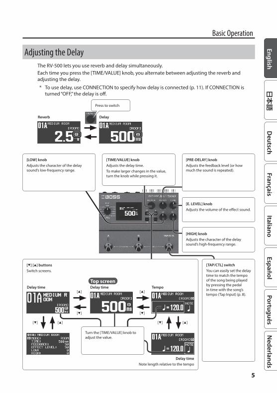
Adjusting the DelayThe RV-500 lets you use reverb and delay simultaneously.Each time you press the [TIME/VALUE] knob, you alternate between adjusting the reverb and adjusting the delay.
* To use delay, use CONNECTION to specify how delay is connected (p. 11). If CONNECTION is turned “OFF,” the delay is off.
DelayReverb
Press to switch
[LOW] knobAdjusts the character of the delay sound’s low-frequency range.
[TIME/VALUE] knobAdjusts the delay time.To make larger changes in the value, turn the knob while pressing it.
[E. LEVEL] knobAdjusts the volume of the effect sound.
[TAP/CTL] switchYou can easily set the delay time to match the tempo of the song being played by pressing the pedal in time with the song’s tempo (Tap Input) (p. 8).
[I] [H] buttonsSwitch screens.
[H] [I]
[H]
[I]
[H] [I]
Tempo
Delay timeNote length relative to the tempo
[H]
[I]
Delay timeDelay timeTop screen
Turn the [TIME/VALUE] knob to adjust the value.
[HIGH] knobAdjusts the character of the delay sound’s high-frequency range.
[PRE-DELAY] knobAdjusts the feedback level (or how much the sound is repeated).

6
Basic Operation
Turning Reverb On/Off
Patch A reverbEach time you press the [A] switch, the reverb alternately turns on (lit blue) / off (unlit).
Patch B reverbEach time you press the [B] switch, the reverb alternately turns on (lit blue) / off (unlit).
Press once
Blue: on Unlit: off
MEMO
You can also make settings so that patches A and B are used simultaneously (p. 20).
Patches and BanksSettings for MODE, PRE-DELAY, EFFECT LEVEL, LOW, HIGH, and TIME are collectively called a “patch.” You can select patches using [A], [B], and [TAP/CTL] switches (p. 20). A combination of patches A, B, and C is called a “bank.”
Bank down
Bank upBANK 02
BANK 99
BANK 01
Patch 01A Patch 01B Patch 01C
* If you want to use the [TAP/CTL] switch to select patch C, refer to “Assigning the Functions of the [A], [B], and [TAP/CTL] Switches” (p. 20).

7
Basic Operation
Switching Banks/Patches
1 Switch banks (01–99).
Bank down (press the [A] and [B] switches simultaneously)
Bank up (press the [B] and [TAP/CTL] switches simultaneously)
2 Press a blinking switch ([A] or [B]) to switch patches.
Blinking blue
MEMO
You can recall a different patch by turning the [TIME/VALUE] knob while you hold down the [EXIT] button.
MEMO
5 You can specify whether the reverb sound is or is not retained when switching patches (p. 20).
5 You can change the functions that are controlled by the [A], [B], and [TAP/CTL] switches; for example, you can make the [A] switch turn reverb on/off.

8
Basic Operation
Using the [TAP/CTL] Switch to Control the ReverbWith the initial settings, the [TAP/CTL] switch holds the reverb sound (HOLD); however, you can change this assignment so that the switch varies the way in which reverb is applied.
1 Press the [EDIT] button.
2 Use the [H] [I] buttons to select “CONTROL” and then press the [EDIT] button.
3 Use the [H] [I] buttons to select a parameter, and use the [TIME/VALUE] knob to edit the value.
Parameter Value ExplanationTAP/CTL Specifies the function of the [TAP/CTL] switch.
TAP/CTL MODE (*1)MOMENT The switch is normally off (minimum value), and turns on (maximum value) only while you
hold it down.
TOGGLE The switch alternately switches off (minimum value) and on (maximum value) each time you press it.
HOLD TIME (*2) 0–100 Specifies the time over which the input sound plays back repeatedly.RISE TIME (*3) 0–100 Specifies the time over which the twist effect rises.FALL TIME (*3) 0–100 Specifies the time over which the twist effect falls.
TAP/CTL PREFPATCH Different settings can be made for each patch.SYSTEM The same settings are shared by all patches.
*1: This is shown if TAP/CTL is set to “HOLD,” “TWIST,” or “WARP.”*2: This is shown if TAP/CTL is set to “HOLD.”*3: This is shown if TAP/CTL is set to “TWIST.”
TAP/CTL SettingsValue Explanation
OFF No assignment.HOLD The input sound plays back repeatedly while you hold down the switch.WARP Simultaneously controls the reverb sound’s feedback level and volume to produce a totally unreal reverb.TWIST A new type of reverb that produces an aggressive, spinning sensation.TAP Lets you specify the delay time by tap input.MOMENT Outputs the reverb sound only while you hold down the switch.FADE Fades-in/-out the input sound.BANK UP
Change banks.BANK DOWN
4 Press the [EXIT] button to return to the top screen.

9
Editing a PatchYou can edit a variety of patch-related parameters.
1 Press the [EDIT] button.
2 Use the [H] [I] buttons to select “PATCH,” and then press the [EDIT] button.
3 Use the [H] [I] buttons to select a parameter, and use the [TIME/VALUE] knob to edit the value.
4 Press the [EXIT] button to return to the top screen.
* Save the edited patch as described in the procedure on “Saving a Patch” (p. 10).
Basic [EDIT] operationsUse the [H] [I] buttons to move the cursorUse the [TIME/VALUE] knob to edit the value
[EDIT] button
Use the [H] [I] buttons to move the cursor
[EDIT] button
[EXIT] button

10
Saving a PatchHere’s how to save a patch that you’ve edited.
1 Press the [EXIT] button and [EDIT] button simultaneously.
2 Use the [TIME/VALUE] knob to select the save-destination number.Bank [A] switch [B] switch [TAP/CTL] switch
Bank 01 01A 01B 01CBank 02 02A 02B 02C
: : : :Bank 99 99A 99B 99C
* Patch C can be selected only if FSW MODE (p. 20) is set to “A/B/C.”
3 Press the [H] button to select the patch name.
4 Edit the patch name.[H] [I] buttons Move the cursor[TIME/VALUE] knob Edit the character
5 Press the [EDIT] button to save the patch.If you decide to cancel, press the [EXIT] button.
By moving the cursor to “WRITE TO” and turning the [TIME/VALUE] knob, you can initialize a patch (INIT) or exchange patches (EXCHANGE).

11
Parameter List
PATCH
Parameters Common to All ModesParameter Value Explanation
REVERBMODE Selects the type of reverb (p. 4). The same function as the [MODE] knob.TIME 0.1–10.0 s (*1) Adjusts the length (time) of the reverb sound.PRE-DELAY 0–200 ms Adjusts the time until when the reverb sound is output.EFFECT LEVEL 0–100 Adjusts the volume of the reverb sound.LOW (*2) -50–+50 Adjusts the low frequency range tone.HIGH (*2) -50–+50 Adjusts the high frequency range tone.
LOW CUT (*2) FLAT, 20–800 Hz This sets the frequency at which the low cut filter begins to take effect. When FLAT is selected, the low cut filter will have no effect.
HIGH CUT (*2) 630 Hz–16.0 kHz, FLAT This sets the frequency at which the high cut filter begins to take effect. When FLAT is selected, the high cut filter will have no effect.
LOW DAMP (*3) -50–+50 Adjusts the amount of attenuation for the low frequency region.HIGH DAMP (*3) -50–+50 Adjusts the amount of attenuation for the high frequency region.DENSITY (*4) 1–10 (*5) Adjusts the density of the reverb sound.MOD DEPTH 0–100 Adjusts the depth to which the reverb sound is modulated.MOD RATE 0–100 Adjusts the speed at which the reverb sound is modulated.
*1: If MODE is “EARLY REFLECTION” or “NON-LINEAR (REVERSE),” the range is 0.1–1.0 s.*2: Except when MODE is “SRV” or “SPACE ECHO”*3: Except when MODE is “EARLY REFLECTION,” “NON-LINEAR,” “SRV,” or “SPACE ECHO”*4: Except when MODE is “SFX” or “SPACE ECHO”*5: If MODE is “SRV,” the range is 0–9.
DELAY
CONNECTION OFF, SERIES, PARALLEL
Specifies whether reverb and delay are connected in series (SERIES) or in parallel (PARALLEL). If this is set to “SERIES,” the effects are connected in the order of delay0reverb.If this is set to “OFF,” the delay is off.
TIME 1–2000 ms Adjusts the delay time.
BPMSpecifies the tempo.The range of this setting depends on the TIME or NOTE value.
NOTE ˜–ª Adjusts the delay time. This is specified in terms of a note length relative to the BPM.
FEEDBACK 0–100Adjusts the amount of delay sound that is returned to the input.Higher values produce a larger number of delay repetitions.
EFFECT LEVEL 0–120 Adjusts the volume of the delay sound.LOW -50–+50 Adjusts the low frequency range tone.HIGH -50–+50 Adjusts the high frequency range tone.MOD DEPTH 0–100 Adjusts the depth to which the delay sound is modulated.MOD RATE 0–100 Adjusts the speed at which the delay sound is modulated.
TEMPO HOLD OFF, ON
Specifies whether the tempo (BPM) changes or is maintained when you switch between patches. If the tempo is maintained, the delay time can be maintained. However, if you switch between patches that have different NOTE settings (¸ or ˙ etc.), the delay time will also be different.

12
Parameter List
Parameter Value Explanation
COMMON
CARRYOVER OFF, ON You can specify whether the reverb sound is carried-over when you switch patches or turn the reverb off (p. 20).
DIRECT LEVEL 0–100 Adjusts the volume of the direct sound.INPUT LEVEL 0–100 Adjusts the volume that is input to the reverb and delay.
DUCK SENS 0–100Adjusts the sensitivity at which the volume is automatically adjusted according to the input. Higher values allow the adjustment to occur in response to lower volumes.
DUCK PRE DEPTH 0–100When the input sound is loud, this automatically reduces the volume that is being input to the reverb and delay. As this setting approaches 100, the input volume reduction is applied more deeply.
DUCK POST DEPTH 0–100When the input sound is loud, this automatically reduces the volume that is being output from the reverb and delay. As this setting approaches 100, the output volume reduction is applied more deeply.
OUTPUT GAIN -6–+6 dB Adjusts the output level.
Parameters for Each Mode
ROOMParameter Value ExplanationREVERB
TYPE AMBIENCE, SMALL, MEDIUM, LARGE Selects the size of the room.
HALLParameter Value ExplanationREVERBTYPE SMALL, MEDIUM, LARGE Selects the size of the concert hall.
SPRINGParameter Value ExplanationREVERBSPRING NUMBER 1–3 Selects the number of springs.
SHIMMERParameter Value ExplanationREVERBPITCH 1PITCH 2
-24–+24 Adjusts the amount of pitch shift.
FINE 1FINE 2
-50–+50 Finely adjusts the amount of pitch shift.
RELEASE 1RELEASE 2
0–100 Adjusts the length of the reverberation (PITCH).
LEVEL 1LEVEL 2
0–100 Adjusts the volume of the pitch-shifted sound.

13
Parameter List
FAST DECAYParameter Value ExplanationREVERBDECAY 1–10 Adjusts the decay of the reverb sound.
EARLY REFLECTIONParameter Value ExplanationREVERBTYPE 1–4 Selects the type of effect.ENVELOPE 1–10 Selects the envelope of the reverb.
NON-LINEARParameter Value ExplanationREVERBTYPE GATE, REVERSE Selects the type of reverb.GATETHRESHOLD 0–100 Adjusts the length of the reverb sound.HOLD TIME 0.1–1.0 s Adjusts the time from when the gate is closed until the gate opens next.REVERSEGATE TIME 0.1–1.0 s Adjusts the gate time.
SFXParameter Value ExplanationREVERB
TYPE
Selects the type of reverb.LO-FI Sound quality typical of an AM radio or telephone.SLOWVERB Sound with a gentle rise and soft overtones.STORM Sound that appears to be tossed by a storm.
LO-FILO-FI 1–10 Adjusts the frequency bandwidth of the reverb.DISTORTION 0–10 Adjusts the depth of distortion.
LO-FI LEVEL 0–100 Adjusts the LO-FI portion (sound similar to an AM radio or telephone) to which reverb and delay are not applied.
SLOWVERBRISE TIME 0–100 Adjusts the rise time of the reverb sound.SENS 0–100 Adjust the way in which the reverb sound rises in response to the input.LOWER HARM 0–100 Adjusts the sound of one octave below.UPPER HARM 0–100 Adjusts the sound of one octave above.UNISON MIX 0–100 Adjusts the sound at the same pitch as the input.DETUNE 0–100 Adjusts the modulation of the overtone sound.STORMCOLOR 0–100 Adjusts the character of the reverb.DEPTH 0–100 Adjusts the depth to which the reverb sound is modulated.SPEED 0–100 Adjusts the speed at which the reverb sound is swept.

14
Parameter List
DUALParameter Value ExplanationREVERBTYPE1TYPE2
ROOM, HALL, PLATE, SPRING Selects the type of reverb (p. 4). The same function as the [MODE] knob.
TIME1TIME2
0.1–10.0s Adjusts the length (time) of the reverb sound.
PRE-DELAY1PRE-DELAY2
0–200 ms Adjusts the time until the reverb sound is output.
LOW1LOW2
-50–+50 Adjusts the character of the low frequency region.
HIGH1HIGH2
-50–+50 Adjusts the character of the high frequency region.
DENSITY1DENSITY2
1–10 Adjusts the density of the reverb sound.
EFFECT LEVEL1EFFECT LEVEL2
0–100 Adjusts the volume of the reverb sound.
CROSSOVER PARALLEL, 100 Hz–4.00 kHz
Splits the input into two, and inputs each to a different reverb.If you choose the “PARALLEL” setting, the same signal is input to both.
SRVParameter Value ExplanationREVERB
SELECTION
Selects the type of reverb provided by the Roland SRV-2000 digital reverb.P-A Plate reverb.P-B Plate reverb with a sound that's more flamboyant than P-A.H37–H15 Hall reverb. Increasing this value increases the size of the concert hall.R37–R0.3 Room reverb. Increasing this value increases the size of the room.
HF DAMP 0.05–1.00 Adjusts the high frequency components of the reverb sound.DENSITY 0–9 Adjusts the density of the late reverberation.ATTACK GAIN 0–9 Adjusts the gain of the early reflections.ATTACK TIME 0–9 Adjusts the time of the early reflections.ER DENSITY 0–9 Adjusts the density of the early reflections.ER LEVEL 0–99 Adjusts the volume of the early reflections.LOW GAIN -24–+12 dB Adjusts the amount of boost/cut for the low frequency region.LOW FREQ 0.04–1.00 kHz Specifies the center frequency of the low frequency region.MID GAIN -24–+12 dB Adjusts the amount of boost/cut for the mid frequency region.MID FREQ 0.25–9.99 kHz Specifies the center frequency for the mid frequency region.
MID Q 0.2–9.0 Specifies the bandwidth of the mid frequency region. Larger values make the bandwidth narrower.
HIGH GAIN -24–+12 dB Adjusts the amount of boost/cut for the high frequency region.HIGH FREQ 0.80–9.99 kHz Specifies the center frequency for the high frequency region.
HIGH Q 0.2–9.0 Specifies the bandwidth of the high frequency region. Larger values make the bandwidth narrower.

15
Parameter List
SPACE ECHOParameter Value Explanation
ECHOREPEAT RATE 1 ms–10.0 s Adjusts the spacing of the echoes (delay time).
BPMSpecifies the tempo.The range of this setting depends on the REPEAT RATE and NOTE values.
NOTE ˜–ª Adjusts the delay time. This is specified in terms of a note length relative to the BPM.
INTENSITY 0–100 Adjusts the volume of the repeated echoes (the amount of feedback).ECHO VOLUME 0–120 Adjusts the volume of the echoes.HEAD SELECT 1–1+2+3 Selects the combination of playback heads.BASS -50–+50 Adjusts the low frequency region of the echo.TREBLE -50–+50 Adjusts the high frequency region of the echo.

16
Parameter List
CONTROLYou can specify the functions of the [TAP/CTL] switch and of a footswitch or expression pedal connected to the CTL 1,2/EXP jack.
5 “Using the [TAP/CTL] Switch to Control the Reverb” (p. 8)
5 “Assigning a Function to an External Pedal” (p. 22)
ASSIGN
ASSIGN INPUT SENSParameter Value Explanation
ASGN INPUT SENS 0–100 Adjusts the input sensitivity when “INPUT” is selected for SRC.
ASSIGN 1–8Parameter Value Explanation
SW OFF, ON Turns the ASSIGN 1–8 on/off.
SRC (SOURCE)
Specifies the controller (source).TAP/CTL [TAP/CTL] switch.
EXP PDL(EXP PEDAL)
External expression pedal (EV-30, EV-5 etc.; sold separately) connected to the CTL 1,2/EXP jack.
CTL1, 2 PDL External footswitch connected to the CTL 1,2/EXP jack.
INT PDL
Internal pedalThe virtual expression pedal will begin operating when started by the specified trigger (TRIGGER), modifying the parameter specified by “TARGET.”For details on the parameters that can be assigned to the internal pedal, refer to “TIME” and “CURVE” (p. 17)
WAVE PDL
Wave pedalThe virtual expression pedal will cyclically modify the parameter specified by “TARGET” in a fixed wave form.
INPUT
(INPUT LEVEL)
The assigned target parameter will change according to the input level.
* If you want to adjust the input sensitivity, set the SENS (INPUT SENS).CC#1–31, CC#64–95 Controller number from an external MIDI device
MODE (SOURCE MODE)
Specifies the operation of the controller.
MOMENTThe value will normally be OFF (minimum value), and will be ON (maximum value) only while the control is being operated.
* If you want to use the internal pedal or wave pedal, set to “MOMENT.”
TOGGLE The value will toggle between OFF (minimum) and ON (maximum) each time the control is operated.
TRG (TARGET) This selects the parameter to be changed.
MIN (TARGET MIN)MAX (TARGET MAX)
Specifies the range of change for the parameter. The values will depend on the parameter that’s assigned by “TARGET.”

17
Parameter List
Parameter Value Explanation
ACT LOW 0–126 Within the operating range of the source, this specifies the range that will control the target parameter.The target parameter will be controlled within the range specified. Normally, you should leave ACT LOW at “0” and ACT HIGH at “127.”ACT HIGH 0–127
WAVE RATE (*1)0–100, – Specifies the time for one cycle of the wave pedal.
* If, due to the tempo, the time is longer than the range of allowable settings, it is then synchronized to a period either 1/2 or 1/4 of that time.
WAVE FORM (*1) SAW, TRI, SIN
Select one of the following to specify the change produced by the wave pedal.
SAW TRI SIN
TRIGGER(INT PEDAL TRIGGER)(*2)
Specifies how the motion of the internal pedal will be triggered.
PAT CNG(PATCH CHANGE)
This is activated when a patch is selected.
EXP LOWThis is activated when an external expression pedal connected to the CTL 1,2/EXP jack is set to the minimum position.
EXP MIDThis is activated when the external expression pedal connected to the CTL 1,2/EXP jack is moved through the middle position.
EXP HIGHThis is activated when the external expression pedal connected to the CTL 1,2/EXP jack is set to the maximum position.
CTL1, 2 PDLThis is activated when an external footswitch connected to the CTL 1,2/EXP jack is operated.
CC#1–#31CC#64–#95
This is activated when a control change is received.
TIME(INT PEDAL TIME)(*2)
0–100This specifies the time over which the internal pedal will move from the toe-raised position to the toe-down position.
CURVE(INT PEDAL CURVE)(*2)
LINEAR, SLOW (SLOW RISE), FAST (FAST RISE)
Select one of the following curves to specify the change produced by the internal pedal.
LINEAR SLOW FAST
*1: SRC=WAVE PDL only*2: SRC=INT PDL only

18
Parameter List
BANKYou can specify how patches A and B are connected and output when using simul mode.
5 “Using Two Patches Simultaneously (Simul Mode)” (p. 21)
SYSTEMParameter Value Explanation
CONTRAST 1–16 Adjusting the contrast of the display
OUTPUT
Selects how output occurs.STEREO Stereo output.
A:DIR B:EFX Direct sound is output from the OUTPUT A/MONO jack, and effect sound is output from the B jack.
DIRECT MUTE The direct sound is not output; only the effect sound is output.
BANK MODE
Specifies the timing at which the patch is changed when you change banks.
WAITSwitching the bank only changes the indication of the screen, and does not switch the patch at that point. When you press the [A] or [B] switch, the bank and number are finalized, and operation switches to the next patch.
IMMEDIATE Operation immediately switches to the next patch when you switch banks.BANK EXTENT MIN 01–99 Sets the lower limit for the banks.BANK EXTENT MAX 01–99 Sets the upper limit for the banks.KNOB LOCK OFF, ON Specifies whether knob operations are disabled (ON) or not disabled (OFF).
KNOB MODE IMMEDIATE, HOOKWhen you move a knob, this setting specifies whether control data for that knob position is always output (IMMEDIATE) or is output only after the knob position has passed through the current value of the parameter (HOOK).
BYPASS BUFFERED, TRUE Specifies how the bypass sound is output (buffered bypass or true bypass).
PEDAL ACT PUSH, RELEASE Specifies whether the operation occurs when you press the [A], [B], or [TAP/CTL] switch or when you release the switch.
FSW MODE Specifies how the footswitch is used (p. 20).USB MODE Specifies the USB operating mode (p. 25).
MIDIParameter Value Explanation
Rx CHANNEL Ch.1–16, OFFSpecifies the receive channel.If this is “OFF,” MIDI messages are not received.
Tx CHANNEL Ch.1–16, Rx, OFFSpecifies the transmit channel.If this is “OFF,” MIDI messages are not transmitted.
PC IN OFF, ON Specifies whether program changes are received.PC OUT OFF, ON Specifies whether program changes are transmitted.
BANK SEL OUT MSB, M+L
Specifies the bank select message that is transmitted simultaneously with the program change.If you select MSB, only MSB (CC#0) is transmitted. If you select M+L, both MSB and LSB (CC#32) are transmitted.
CC IN OFF, ON Specifies whether control changes are received.CC OUT OFF, ON Specifies whether control changes are transmitted.

19
Parameter List
Parameter Value Explanation
TIME CC (R)
OFF, CC#1–31, 64–95
[TIME/VALUE] knob (reverb)
Specifies the controller number of the corresponding knobs or switches.The parameters that can be controlled differ depending on the mode.
MEMOFor details on MIDI, refer to “MIDI Implementation” (PDF).http://www.boss.info/manuals/
PRE-DLY CC (R) [PRE-DELAY] knob (reverb)E.LEVEL CC (R) [E. LEVEL] knob (reverb)LOW CC (R) [LOW] knob (reverb)HIGH CC (R) [HIGH] knob (reverb)TIME CC (D) [TIME/VALUE] knob (delay)PRE-DLY CC (D) [PRE-DELAY] knob (delay)E.LEVEL CC (D) [E. LEVEL] knob (delay)LOW CC (D) [LOW] knob (delay)HIGH CC (D) [HIGH] knob (delay)
EFFECT SWEFFECT A SWEFFECT B SW
Specifies the controller number that switches between effect-on and bypass.
CTL1 CC External CTL1 switchCTL2 CC External CTL2 switchEXP CC External EXP pedal
SYNC
Selects the tempo clock input that is used for synchronization.INTERNAL Synchronizes to the internal tempo.EXT (USB) Synchronizes to the tempo from the USB port.EXT (MIDI) Synchronizes to the tempo from the MIDI IN connector.
AUTO
Normally synchronizes to the internal tempo, but if MIDI clock is being input from the MIDI IN connector or the USB port, the tempo is synchronized to MIDI clock (AUTO).If the RV-500 is a slave device, choose the “AUTO” setting.
REALTIME SRC
Selects the source of the realtime messages that are transmitted from the MIDI OUT connector or the USB port.INT Internal realtime messages are the source.USB Realtime messages from the USB port are the source.MIDI Realtime messages from the MIDI IN connector are the source.
MIDI IN->OUTUSB IN->OUT
Specifies the connector to which MIDI messages received from the MIDI IN connector and the USB port are output.OFF MIDI messages are not output.USB MIDI messages are output to the USB port.MIDI MIDI messages are output to the MIDI OUT connector.U+M MIDI messages are output to the USB port and the MIDI OUT connector.
DEVICE ID 1–32 Sets the MIDI Device ID used for transmitting and receiving System Exclusive messages.
MIDI PC MAPParameter Value Explanation
BNK-PC# 1:001–3:128 01A–99C Specifies the program number that corresponds to each patch number.

20
Convenient Functions
Specifying Whether to Carry-Over the Reverb SoundYou can specify whether the effect sound is carried-over (ON/OFF) when you switch patches or turn the reverb off.
1 Press the [EDIT] button.
2 Use the [H] [I] buttons to select “PATCH,” and then press the [EDIT] button.
3 Use the [H] [I] buttons to select “CARRYOVER,” and use the [TIME/VALUE] knob to select ON / OFF.
4 Press the [EXIT] button to return to the top screen.
* If FSW MODE (p. 20) is set to “A/B SIMUL,” the effect sound is not carried-over even if CARRYOVER is ON.
Assigning the Functions of the [A], [B], and [TAP/CTL] Switches
1 Press the [EDIT] button.
2 Use the [H] [I] buttons to select “SYSTEM” and then press the [EDIT] button.
3 Use the [H] [I] buttons to select “FSW MODE,” and use the [TIME/VALUE] knob to select the mode.Mode Explanation
NORMALUse the [A] and [B] switches to select patch A or patch B.You can use the [TAP/CTL] switch to hold the reverb or to input the tap tempo.
A/B/CUse the [TAP/CTL] switch to select patch C.
* In this case, you can’t use the [TAP/CTL] switch to change how the reverb is applied.
A/B SIMUL Patches A and B can be used simultaneously (p. 21). Press the unlit [A] or [B] switch to make both light.
SW DN/UP Use the [A] switch to turn effect on/off, and use the [B] switch and [TAP/CTL] switch to change patches.
4 Press the [EXIT] button to return to the top screen.
21
Convenient Functions
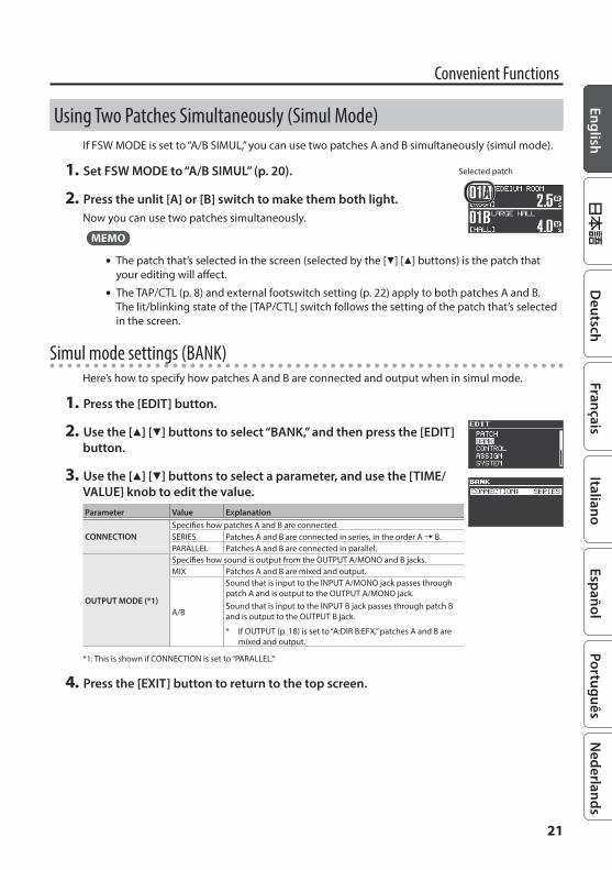
Using Two Patches Simultaneously (Simul Mode)If FSW MODE is set to “A/B SIMUL,” you can use two patches A and B simultaneously (simul mode).
1 Set FSW MODE to “A/B SIMUL” (p. 20).
2 Press the unlit [A] or [B] switch to make them both light.Now you can use two patches simultaneously.
MEMO
5 The patch that’s selected in the screen (selected by the [I] [H] buttons) is the patch that your editing will affect.
5 The TAP/CTL (p. 8) and external footswitch setting (p. 22) apply to both patches A and B. The lit/blinking state of the [TAP/CTL] switch follows the setting of the patch that’s selected in the screen.
Simul mode settings (BANK)Here’s how to specify how patches A and B are connected and output when in simul mode.
1 Press the [EDIT] button.
2 Use the [H] [I] buttons to select “BANK,” and then press the [EDIT] button.
3 Use the [H] [I] buttons to select a parameter, and use the [TIME/VALUE] knob to edit the value.Parameter Value Explanation
CONNECTIONSpecifies how patches A and B are connected.SERIES Patches A and B are connected in series, in the order A0B.PARALLEL Patches A and B are connected in parallel.
OUTPUT MODE (*1)
Specifies how sound is output from the OUTPUT A/MONO and B jacks.MIX Patches A and B are mixed and output.
A/B
Sound that is input to the INPUT A/MONO jack passes through patch A and is output to the OUTPUT A/MONO jack.Sound that is input to the INPUT B jack passes through patch B and is output to the OUTPUT B jack.
* If OUTPUT (p. 18) is set to “A:DIR B:EFX,” patches A and B are mixed and output.
*1: This is shown if CONNECTION is set to “PARALLEL.”
4 Press the [EXIT] button to return to the top screen.
Selected patch

22
Assigning a Function to an External PedalYou can assign a function to a footswitch (sold separately: FS-5U, FS-5L, FS-6, FS-7) or expression pedal (sold separately: EV-30, Roland EV-5 etc.) connected to the CTL 1,2/EXP jack.
1 Press the [EDIT] button.
2 Use the [H] [I] buttons to select “CONTROL,” and then press the [EDIT] button.
3 Use the [H] [I] buttons to select a parameter, and use the [TIME/VALUE] knob to edit the value.
Parameter Value ExplanationCTL 1/2 FUNC Specifies the function of a footswitch connected to the CTL 1,2/EXP jack.
CTL 1/2 MODE (*1)MOMENT The switch is normally off (minimum value), and turns on (maximum value) only while you
hold it down.
TOGGLE The switch alternately switches off (minimum value) and on (maximum value) each time you press it.
HOLD TIME (*2) 0–100 Specifies the time for which the reverb sound is held.RISE TIME (*3) 0–100 Specifies the time over which the twist effect rises.FALL TIME (*3) 0–100 Specifies the time over which the twist effect falls.EXP FUNC Specifies the function of an expression pedal connected to the CTL 1,2/EXP jack.TRG MIN Specify the minimum value (MIN) and maximum value (MAX) of the parameter that is controlled by the
expression pedal. The values depend on the parameter that is assigned in EXP FUNC.TRG MAXCTL 1/2 PREFEXP PREF
PATCH Different settings can be made for each patch.SYSTEM The same settings are shared by all patches.
*1: This is shown if TAP/CTL is set to “HOLD,” “TWIST,” or “WARP.”*2: This is shown if TAP/CTL is set to “HOLD.”*3: This is shown if TAP/CTL is set to “TWIST.”
CTL1 FUNC and CTL2 FUNC SettingsValue Explanation
OFF No assignment.HOLD Holds the reverb sound while you hold down the switch.WARP Simultaneously controls the reverb sound’s feedback level and volume to produce a totally unreal reverb.TWIST A new type of reverb that produces an aggressive, spinning sensation.TAP Lets you specify the delay time by tap input.MOMENT Outputs the reverb sound only while you hold down the switch.FADE Fades-in/-out the input sound.BANK UP
Change banks.BANK DOWN

23
Assigning a Function to an External Pedal
EXP FUNC SettingsValue Explanation
OFF No function is assigned. Select this if you’re using the ASSIGN1–8 setting (p. 16).RV TIME Controls the reverb time. RV PRE-DLY Adjusts the time until when the reverb sound is output.RV LOW Adjusts the character of the effect sound’s low-frequency range.RV HIGH Adjusts the character of the effect sound’s high-frequency range.RV LEVEL Controls the reverb level. RV MOD DPT Adjusts the depth to which the reverb sound is modulated.RV MOD RAT Adjusts the speed at which the reverb sound is modulated.DL TIME Controls the delay time. DL F.BACK Adjusts the amount of delay sound that is returned to the input.DL LOW Adjusts the character of the delay sound’s low-frequency range.DL HIGH Adjusts the character of the delay sound’s high-frequency range.DL LEVEL Controls the delay level. DL MOD DPT Adjusts the depth to which the delay sound is modulated.DL MOD RAT Adjusts the speed at which the delay sound is modulated.
4 Press the [EXIT] button to return to the top screen.
24
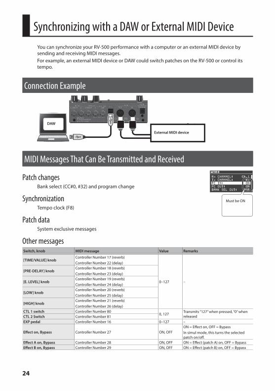
Synchronizing with a DAW or External MIDI DeviceYou can synchronize your RV-500 performance with a computer or an external MIDI device by sending and receiving MIDI messages.For example, an external MIDI device or DAW could switch patches on the RV-500 or control its tempo.
Connection Example
External MIDI device
DAW
MIDI Messages That Can Be Transmitted and Received
Patch changesBank select (CC#0, #32) and program change
SynchronizationTempo clock (F8)
Patch dataSystem exclusive messages
Other messagesSwitch, knob MIDI message Value Remarks
[TIME/VALUE] knob Controller Number 17 (reverb)Controller Number 22 (delay)
0–127 –
[PRE-DELAY] knobController Number 18 (reverb)Controller Number 23 (delay)
[E. LEVEL] knobController Number 19 (reverb)Controller Number 24 (delay)
[LOW] knobController Number 20 (reverb)Controller Number 25 (delay)
[HIGH] knobController Number 21 (reverb)Controller Number 26 (delay)
CTL 1 switch Controller Number 800, 127 Transmits “127” when pressed, “0” when
releasedCTL 2 Switch Controller Number 81EXP pedal Controller Number 16 0–127 –
Effect on, Bypass Controller Number 27 ON, OFFON = Effect on, OFF = BypassIn simul mode, this turns the selected patch on/off.
Effect A on, Bypass Controller Number 28 ON, OFF ON = Effect (patch A) on, OFF = BypassEffect B on, Bypass Controller Number 29 ON, OFF ON = Effect (patch B) on, OFF = Bypass
Must be ON

25
Synchronizing with a DAW or External MIDI Device
MIDI RoutingFor details on how to set the MIDI parameters, refer to “Basic [EDIT] operations” (p. 9).
Main Setting ItemsItem Parameter Explanation
Synchronization source SYNCSpecifies whether the synchronization source is the RV-500 (INTERNAL), USB, or an external device connected via MIDI.
Realtime messages REALTIME SRCSpecifies whether realtime messages generated by the RV-500 are transmitted, and whether realtime messages received via the MIDI IN connector or the USB port are transmitted.
MIDI message output destination
MIDI IN->OUT Specifies the MIDI messages that are transmitted from the MIDI OUT connector.
USB IN->OUT Specifies the MIDI messages that are transmitted from the USB port.
If you experience problems connecting with your DAWNormally, you don’t need to install a driver in order to connect the RV-500 to your computer. However, if some problem occurs, or if the performance is poor, using the BOSS original driver may solve the problem.In this case, setting “USB MODE” to “VENDOR” on the RV-500, install the driver on your personal computer.For details on downloading and installing the BOSS original driver, refer to the BOSS website. For further details, refer to the Readme.htm file that comes with the download.& http://www boss info/support/The program you need to use, and the steps you need to take to install the USB driver will differ depending on your computer setup, so please carefully read and refer to the Readme.htm file that comes with the download.

26
Restoring the Factory Default SettingsHere’s how to reset the settings to their factory state. If you like, you can also reset the system settings or just a specific range of patches.
1 Press the [EDIT] button.
2 Use the [H] [I] buttons to select “FACTORY RESET,” and then press the [EDIT] button.
3 Use “FROM” and “TO” to specify the range that you want to reset.Parameter Value Explanation
FROMTO
SYSTEM System parameter settings.01A–99C Settings for Patches.BANK01–99 Settings for Banks (Patch A–C, BANK parameters).
4 Press the [EDIT] button.A confirmation message appears.
5 Press the [EDIT] button to reset the settings.If you decide to cancel without resetting, press the [EXIT] button.
Transmitting Data to an External MIDI DeviceYou can use Exclusive messages to set another RV-500 to the same settings or to save effect sound settings to MIDI sequencers and other such devices. This transmission of data is referred to as bulk dump.
1 Press the [EDIT] button.
2 Use the [H] [I] buttons to select “MIDI BULK DUMP,” and then press the [EDIT] button.
3 Use “FROM” and “TO” to specify the range that you want to reset.Parameter Value Explanation
FROMTO
SYSTEM System parameter settings.01A–99C Settings for Patches.BANK01–99 Settings for Banks (Patch A–C, BANK parameters).TEMP Current reverb settings in the panel display.
4 Press the [EDIT] button.The bulk dump is executed.

27
TroubleshootingProblem Items to check Action
Power does not turn on
Is your guitar correctly connected to the INPUT A/MONO jack? Check the connection once again.
Could the batteries be low? Install fresh batteries.Is the specified PSA-S series AC adaptor connected correctly? Check the connection once again.
No sound is output / No reverb sound is output / No direct sound is output
Is the SYSTEM: OUTPUT (p. 18) setting correct? Check the SYSTEM: OUTPUT (p. 18) setting
and the OUTPUT jacks connection.Is your output device correctly connected to the OUTPUT jacks?
Footswitch does not change sounds as you expect
Is the SYSTEM: FSW MODE (p. 20) setting correct?
The FSW MODE (p. 20) setting determines what happens when you press the [A], [B], and [TAP/CTL] switches. Check the setting.
Reverb sound does not remain when you switch patches or turn off the reverb
Is the PATCH: CARRYOVER (p. 20) setting “ON”?
If CARRYOVER (p. 20) is set to “OFF” the reverb sound does not remain.
Could the SYSTEM: BYPASS (p. 18) setting be “TRUE”?
If this is set to “TRUE” (True bypass), the reverb sound cannot be carried-over when the effect is turned off even if CARRYOVER is turned “ON.” Set SYSTEM: BYPASS to “BUFFERED.”
Could the SYSTEM: FSW MODE (p. 20) setting be “A/B SIMUL”?
If this is set to “A/B SIMUL,” the reverb sound cannot be carried-over when the effect is turned off even if CARRYOVER is turned “ON.”Check the setting.
Main Specifications
BOSS RV-500: ReverbPower Supply
Alkaline battery (AA, LR6) x 4AC adaptor
Current Draw 225 mA
Battery Life for Continuous Use
Alkaline batteries (AA, LR6): Approximately 4.5 hours
* This figure will vary depending on the actual conditions of use.
Dimensions170 (W) x 138 (D) x 62 (H) mm6-3/4 (W) x 5-7/16 (D) x 2-1/2 (H) inches
Weight (including batteries)1.0 kg2 lbs 4 oz
Accessories Owner’s manual, Leaflet “USING THE UNIT SAFELY,” Alkaline Batteries (AA LR6) x 4
Options (sold separately)
AC adaptor: PSA-S seriesFootswitch: FS-5U, FS-5LDual Footswitch: FS-6, FS-7Expression pedal: FV-500H, FV-500L, EV-30, Roland EV-5
* 0 dBu = 0.775 Vrms* This document explains the specifications of the product at the time that the document was issued. For the latest information, refer to the
Roland website.
28
USING THE UNIT SAFELY
Keep small items out of the reach of childrenTo prevent accidental ingestion of the parts listed below, always keep them out of the reach of small children.• Included Parts
Rubber feet (p. 2)
IMPORTANT NOTESPower Supply: Use of Batteries• Batteries should always be installed or replaced before
connecting any other devices. This way, you can prevent malfunction and damage.
• If operating this unit on batteries, please use alkaline batteries.
Repairs and Data• Before sending the unit away for repairs, be sure to make
a backup of the data stored within it; or you may prefer to write down the needed information. Although we will do our utmost to preserve the data stored in your unit when we carry out repairs, in some cases, such as when the memory section is physically damaged, restoration of the stored content may be impossible. Roland assumes no liability concerning the restoration of any stored content that has been lost.
Additional Precautions• Any data stored within the unit can be lost as the result of
equipment failure, incorrect operation, etc. To protect yourself against the irretrievable loss of data, try to make a habit of creating regular backups of the data you’ve stored in the unit.
• Roland assumes no liability concerning the restoration of any stored content that has been lost.
• Never strike or apply strong pressure to the display.
• Do not use connection cables that contain a built-in resistor.
Intellectual Property Right• This product contains eParts integrated software platform of
eSOL Co.,Ltd. eParts is a trademark of eSOL Co., Ltd. in Japan.
• Roland, BOSS, and SPACE ECHO are either registered trademarks or trademarks of Roland Corporation in the United States and/or other countries.
• Company names and product names appearing in this document are registered trademarks or trademarks of their respective owners.