bosch turboscara sr6 / sr8 planning manual - uniroma1.itdeluca/rob1_en/product_bosch-sr6sr8.pdf ·...
TRANSCRIPT
DVVHPEO\�WHFKQRORJ\
Bosch turboscara SR6 / SR8planning manual
Ausgabe
1.0

turboscara from Bosch 1
3842 525 231 (99.08) en
ContentsPage
1 turboscara from Bosch ...................................................................3
2 System components........................................................................4
3 Robot turboscara SR6/SR8 .............................................................6
3.1 Variations...........................................................................................63.2 Aspects..............................................................................................83.2.1 turboscara SR6..................................................................................83.2.2 turboscara SR8..................................................................................93.2.3 turboscara SR-DP............................................................................103.2.4 Base plate........................................................................................103.2.5 Bracket ............................................................................................113.2.6 Gripper flange..................................................................................123.2.7 Driveless teaching (optional, in the making).....................................123.3 Mounting of periphery ......................................................................13
4 IQ 200 controller ............................................................................16
4.1 Components ....................................................................................174.1.1 rho4.1 controller computer...............................................................174.1.2 Power supply EVS ...........................................................................204.1.3 AV200 drive booster ........................................................................214.2 Technical data of the controller........................................................22
5 Accessories....................................................................................24
5.1 turboscara SR6/SR8........................................................................245.1.1 Tool Connector ................................................................................245.1.2 Pneumatic parallel gripper ...............................................................265.2 IQ 200 controller ..............................................................................275.2.1 Operating block ...............................................................................275.2.2 Touchscreen BF200T ......................................................................285.2.3 PHG2000 hand-held programming device .......................................295.2.4 Software ..........................................................................................305.2.5 Licensing the software .....................................................................325.2.6 I/O-Module.......................................................................................335.2.7 Further bus connections ..................................................................345.2.8 Control cabinet ................................................................................35
6 Layout criteria................................................................................36
6.1 Load capacity ..................................................................................366.2 Mass moment of inertia ...................................................................366.3 Reaction forces................................................................................366.4 Permissible load at gripper flange....................................................376.5 Working area...................................................................................386.5.1 Planning sheet for the SR6..............................................................386.5.2 Planning sheet for the SR8..............................................................39
2 turboscara from Bosch
3842 525 231 (99.07) de
6.6 Cycle time........................................................................................406.6.1 Cycle time determination .................................................................406.6.2 Cycle time diagrams ........................................................................426.7 I/O expansion ..................................................................................436.8 Ambient conditions ..........................................................................446.9 Other marginal conditions ................................................................44
7 Ordering .........................................................................................46
7.1 Notes on ordering ............................................................................467.2 Example...........................................................................................467.3 Order forms .....................................................................................477.3.1 Robot system complete ...................................................................477.3.2 Swivel arm robot turboscara SR6/SR8.............................................487.3.3 Options ............................................................................................497.3.4 Accessories .....................................................................................507.3.5 Documentation.................................................................................517.3.6 Licences ..........................................................................................537.3.7 Further components from the Bosch AT programme .......................53
8 Service............................................................................................54
8.1 Automation technology, robot technology division ...........................548.2 Sales ...............................................................................................548.3 Training ...........................................................................................558.4 Hotline .............................................................................................55
9 Appendix ........................................................................................57
9.1 Accessories from other manufactures..............................................579.2 Alphabetical Index ...........................................................................60

turboscara from Bosch 3
3842 525 231 (99.08) en
1 turboscara from BoschThe turboscara SR6 and SR8 are swivel arm robots (scara robots) withfour-axes that have the following advantages
• Minimum cycle time with highest precision
• Large work space and various lift strokes
• Defined mechanical interfaces
• PC-control with a wide range of communication possibilities
• Conforms to international standards
• Brushless drive technology reduces repairs
• Integrated user installation, as an option: down to gripper for attaching aTool Connector
• Integration of safety technology (safety class 3) is standard
• User power supply (24 V) in control rack
• Program language BAPS can be learned quickly and also allows thecreation of clear and understandable programs; new with BAPSplus:graphical program interface
• Can be expanded via compact and flexible input/output modules: B~IOmodules or decentralised CAN-I/O modules
• Expandable via valve block system VTS02 with CAN connection fortime-saving installation
The performance can also be seen in the accompanying service offer
• Comprehensive hotline service for all of your questions concerning therobots
• Competent representatives in your area: our products are sold throughone of our contract partners
• Fast on-site service from Bosch’s customer service department or oneof our contract partners
• Practical training of your employees in our training center.
4 System components
3842 525 231 (99.07) de
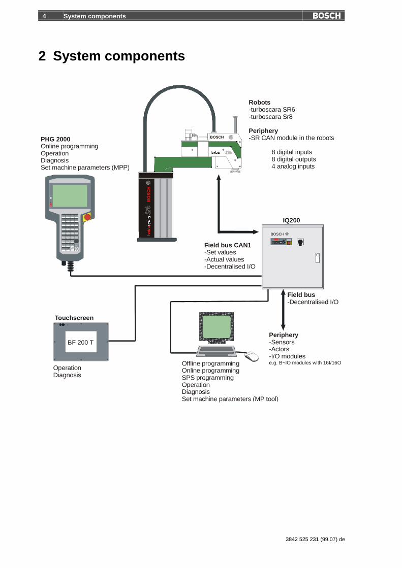
2 System components
BF 200 T
Touchscreen
IQ200
BOSCH
BO
SC
H
BOSCH
WXUER
WXUERVFDUD
PHG 2000Online programmingOperationDiagnosisSet machine parameters (MPP)
Robots
Periphery
-turboscara SR6-turboscara Sr8
-SR CAN module in the robots
8 digital inputs8 digital outputs4 analog inputs
Field bus CAN1-Set values-Actual values-Decentralised I/O
Field bus-Decentralised I/O
Periphery-Sensors-Actors-I/O modulese.g. B~IO modules with 16I/16O
OperationDiagnosis
Offline programmingOnline programmingSPS programmingOperationDiagnosisSet machine parameters (MP tool)

System components 5
3842 525 231 (99.08) en
The robot system SR6/SR8 consists of robust robotic mechanics with fourfreely programmable axes. With its high velocity and high loading capacity(up to 8 kg) the robot is predestined for assembly work and for fast Pick &Place motions.
At the core of the IQ200 robot controller is an industrial PC (rho4) with aPentium MMX processor. The power supply (EVS) has a power supplypack for the internal voltage supply (24V) integrated with an emergency offcircuit and safety technology: safety class 3 per EN 954. The digital drivebooster (AV200) for the four individual axes exchanges data with the rho4robot controller via a field bus (CAN 1). All three modules are developed as19” plug-in assemblies.
Decentralised input and output modules or other periphery equipment,such as actuators and sensors, can be controlled via the field bus (CAN 1or CAN 2).
Aside from the operating block, the robot can be operated by a hand-heldprogramming unit (PHG2000), a touch screen (BF200T), or any PC. Akeyboard, mouse, and monitor can also be directly hooked up to the robotcontroller (rho4).
The rho4 or an external PC can be used for programming the robot. Dataor programs are exchanged via the serial interfaces or with the Internetprotocol TCP/IP.
The hand-held programming device PHG2000 is used primarily to teachthe robot and to diagnose errors. It can also change and edit robot pro-grams.
The robot’s movement programs are written in the pascal-like languageBAPS (movement and sequence program language). BAPS robot pro-grams can be created with a text editor or with the graphical programmingtool BAPSplus. When needed, the integrated SoftSPS (PCL) can be pro-grammed by the offline programming software WinSPS.
6 Robot turboscara SR6/SR8
3842 525 231 (99.07) de
3 Robot turboscara SR6/SR8
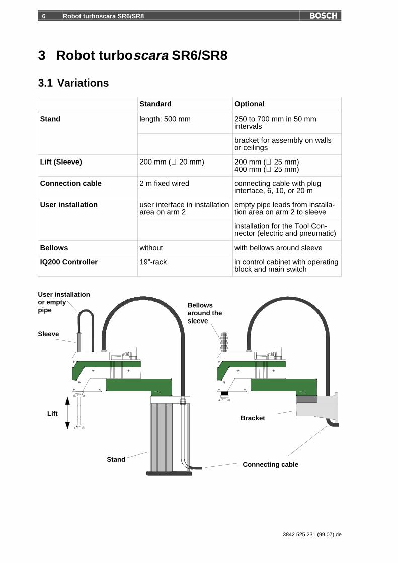
3.1 Variations
Standard Optional
length: 500 mm 250 to 700 mm in 50 mmintervals
Stand
bracket for assembly on wallsor ceilings
Lift (Sleeve) 200 mm (∅ 20 mm) 200 mm (∅ 25 mm)400 mm (∅ 25 mm)
Connection cable 2 m fixed wired connecting cable with pluginterface, 6, 10, or 20 m
user interface in installationarea on arm 2
empty pipe leads from installa-tion area on arm 2 to sleeve
User installation
installation for the Tool Con-nector (electric and pneumatic)
Bellows without with bellows around sleeve
IQ200 Controller 19”-rack in control cabinet with operatingblock and main switch
Bracket
Stand
User installationor emptypipe
Lift
Sleeve
Connecting cable
Bellowsaround thesleeve

Robot turboscara SR6/SR8 7
3842 525 231 (99.08) en
Variation: turboscara SR6/SR8 dust proof
turboscara SR6/SR8 dust proof is for use in especially severe conditions.This robot is completely sealed and uses the full scope of the turboscarafamily performance characteristics in dusty or wet work areas.
8 Robot turboscara SR6/SR8
3842 525 231 (99.07) de
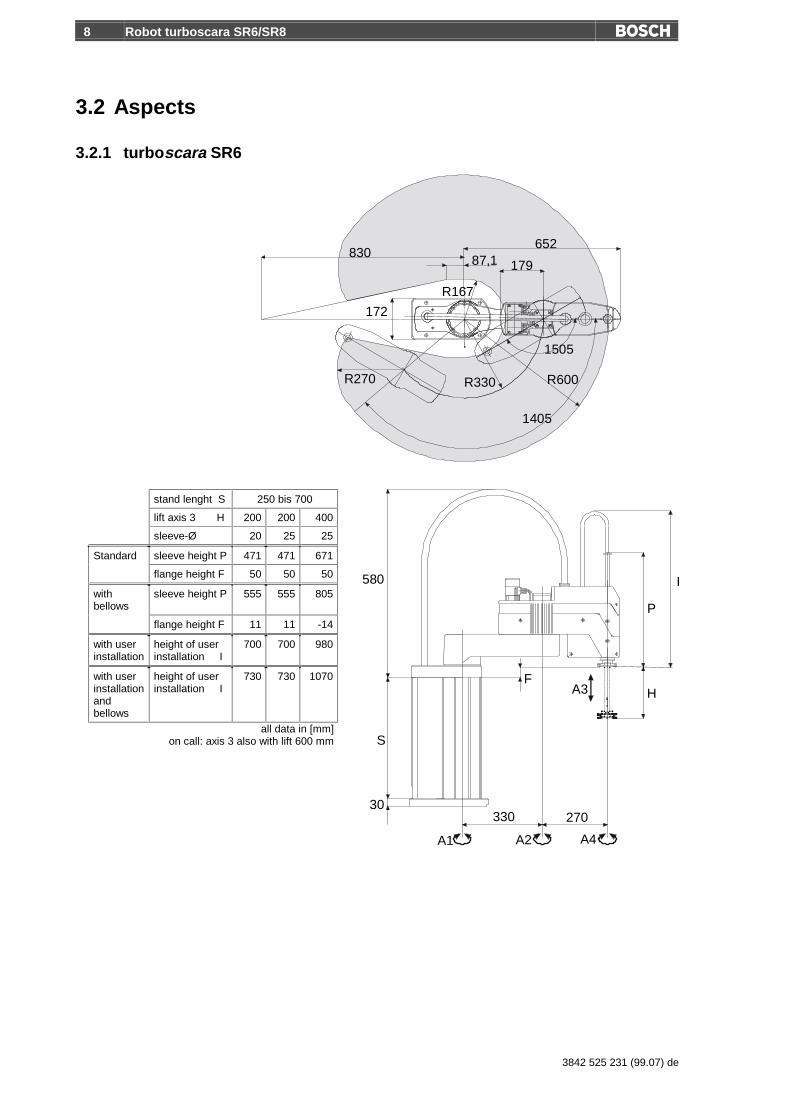
3.2 Aspects
3.2.1 turboscara SR6
83087,1
652
R600
1505
R330R270
1405
A3 H
P
270330
A1 A2 A4
30
S
580
R167
172
F
179
I
stand lenght S 250 bis 700
lift axis 3 H 200 200 400
sleeve-Ø 20 25 25
Standard sleeve height P 471 471 671
flange height F 50 50 50
withbellows
sleeve height P 555 555 805
flange height F 11 11 -14
with userinstallation
height of userinstallation I
700 700 980
with userinstallationandbellows
height of userinstallation I
730 730 1070
all data in [mm]on call: axis 3 also with lift 600 mm
Robot turboscara SR6/SR8 9
3842 525 231 (99.08) en
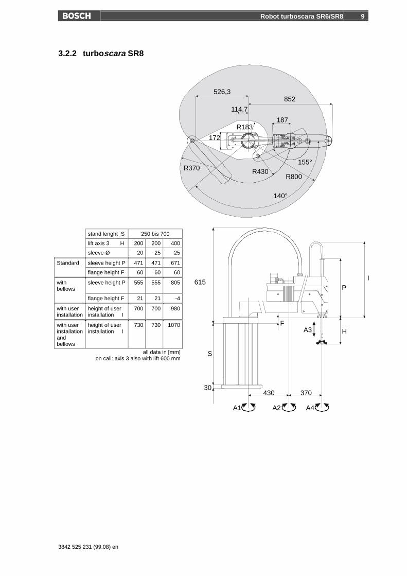
3.2.2 turboscara SR8
526,3
114,7
852
R800R370
172
R430
R183
155°
140°
187
S
30
A1 A2 A4
370430
P
HA3F
I615
stand lenght S 250 bis 700
lift axis 3 H 200 200 400
sleeve-Ø 20 25 25
Standard sleeve height P 471 471 671
flange height F 60 60 60
withbellows
sleeve height P 555 555 805
flange height F 21 21 -4
with userinstallation
height of userinstallation I
700 700 980
with userinstallationandbellows
height of userinstallation I
730 730 1070
all data in [mm]on call: axis 3 also with lift 600 mm
10 Robot turboscara SR6/SR8
3842 525 231 (99.07) de
3.2.3 turboscara SR-DP
For the measurements of the seal variations please inquire at AT/VRO(refer to 8.1). The main measurements are identical to the standard ver-sions, merely the cover on arm 2 is slightly larger.
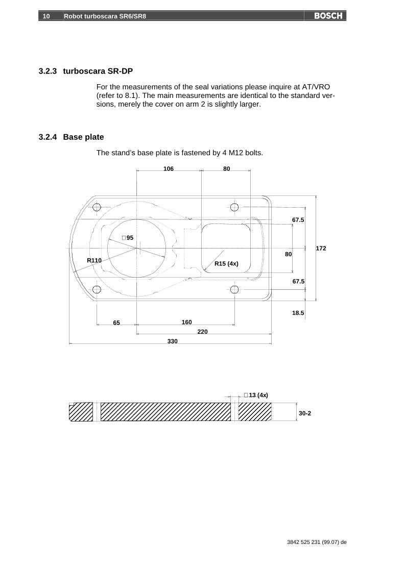
3.2.4 Base plate
The stand’s base plate is fastened by 4 M12 bolts.
330
220
16065
106 80
R110
∅95
∅13 (4x)
30-2
R15 (4x)
172
18.5
80
67.5
67.5

Robot turboscara SR6/SR8 11
3842 525 231 (99.08) en
3.2.5 Bracket
The turboscara SR6/SR8 can also be mounted on the wall or on the ceil-ing. In this case a bracket replaces the stand. This increases the possibili-ties to flexibly arrange your robot’s work area.
325246
173
12.5
25
(140)
54.5 54.52727 0
250
160
115
4444 15
15
150
4x ∅13,5
2x ∅8
2x M5
230
260

12 Robot turboscara SR6/SR8
3842 525 231 (99.07) de
3.2.6 Gripper flange
The gripper flange is mounted on the sleeve and serves as a mount for aTool Connector or other various gripper tools.
∅42
A
∅11
B
∅25∅50 H7
∅63
∅80 h8
∅6.6 (4x)
C
15
6.87
∅6 H7
M6 (4x)
29.122.27
12.06
0
29.122.27
12.06
A
B
∅20 ∅25
∅14 ∅18
Standard Option
CBellows
with; H = 200
with; H = 400
without 61
125
100
22.2
729
.1
12.0
6
012.0
6
22.2
729
.1
31.5
3.2.7 Driveless teaching (optional, in the making)
With this option it is possible to bring the robot flange into the desired position and toactivate the brakes of the axes 3 and 4 directly on the robot with switches. This canmove the robot out of an area or teach points without the drive. The controller mustbe on in order to activate the brakes.

Robot turboscara SR6/SR8 13
3842 525 231 (99.08) en
3.3 Mounting of periphery
On turboscara SR6/SR8 it is possible to mount attachments on the left andright sides of arm 2. For this purpose there are 4 threaded holes M5 (2right, and 2 left) on arm 2.
max.∅14
82
270
82
143
M5
M5
Make sure that the entire load capacity of the robot with all of its at-tachments, grippers, and workpieces does not exceed 5 or 8 kg.

14 Robot turboscara SR6/SR8
3842 525 231 (99.07) de
Technical data of the robot
Load capacity, reaction forces and reaction moments SR6/SR8
Rated load 2 kg
Maximum load (Sleeve ∅20 mm) 5 kg
Maximum load (Sleeve ∅25 mm) 8 kg
Rated maximum mass moment of inertia (Axis 4) 500 kgcm2
Max. mass moment of inertia (Axis 4) 1000 kgcm2
Horizontal force, continuous/max. 60/150 N
Vertical force, continuous/max. 200/300 N
Torque (Axis 4), rated/max. 5/10 Nm
SR6/SR8Positioning range, x, y, z
± 0,025 mm
SR6/SR8Orientation range (Axis 4)
± 0,05 °
Work area SR6 SR8
Reach 600 800 mm
Inside radius 167 183 mm
Swivel angle (Axis 1) +/-140 +/-140
°
Swivel angle (Axis 2) +/-150 +/-155
°
Lift (Sleeve ∅20 mm) 200 200 mm
Lift (Sleeve ∅25 mm, Optional) 200 200 mm
Lift (Sleeve ∅25 mm, Optional) 400 400 mm
Swivel angle (Axis 4) +/-180 +/-180
°
Robot turboscara SR6/SR8 15
3842 525 231 (99.08) en
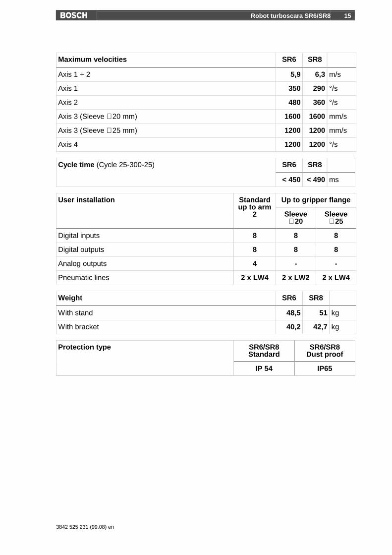
Maximum velocities SR6 SR8
Axis 1 + 2 5,9 6,3 m/s
Axis 1 350 290 °/s
Axis 2 480 360 °/s
Axis 3 (Sleeve ∅20 mm) 1600 1600 mm/s
Axis 3 (Sleeve ∅25 mm) 1200 1200 mm/s
Axis 4 1200 1200 °/s
SR6 SR8Cycle time (Cycle 25-300-25)
< 450 < 490 ms
Up to gripper flangeUser installation Standardup to arm
2 Sleeve∅20
Sleeve∅25
Digital inputs 8 8 8
Digital outputs 8 8 8
Analog outputs 4 - -
Pneumatic lines 2 x LW4 2 x LW2 2 x LW4
Weight SR6 SR8
With stand 48,5 51 kg
With bracket 40,2 42,7 kg
SR6/SR8Standard
SR6/SR8Dust proof
Protection type
IP 54 IP65
16 IQ 200 controller
3842 525 231 (99.07) de
4 IQ 200 controllerThe IQ200 robot controller was designed to control the Bosch swivel-armrobots turboscara SR6/SR8. With its expanded capabilities in parallel proc-essing, even additional tasks can be solved, as for example periphery con-trolling, diagnosis, operator guidance and much more.
The IQ200 is a high-performance PC controller with a Pentium MMX proc-essor and intelligent power boosters whose processor can perform positionFRQWUROOLQJ�LQ������ V�Fycles.
The controller is programmed with the pascal-like BAPS3 programminglanguage. The real time operating system enables the parallel controllingof separate kinematics, cell periphery, and other processes. Data ex-change with other computers, vision systems, or similar sensor systems viainterfaces are also possible from the user program. Several data transferprotocols are available for this data exchange, including TCP/IP protocol.
With the interfaces DDE (Dynamic Data Exchange) and DLL (Dynamic LinkLibrary), the data exchange between the user process and Windows appli-cations is standardised. Aside from the production of your own process in-terfaces, remote control functions and status queries can be made viaWindows applications.
A high performance storage programmable controller (SPS) is available viathe integrated interface modification controller PCL. This controller is stan-dardly used to internally control the system.
IQ200 provides for all required power supplies. An additional, non-controlled power supply with 24 VDC/4 A is available for the system’s pe-riphery. The electrical connections are created with plug or clip technology.

IQ 200 controller 17
3842 525 231 (99.08) en
4.1 Components
4.1.1 rho4.1 controller computer
Plug-in card rho4.1
Processor
The rho4.1 has a high-performance Pentium microprocessor, a 4 MB usermemory for BAPS programs and a 16 MB memory for Windows applica-tions. The microprocessor is sectioned into 2 virtual processors P1 and P2.
The processor P1 is the BAPS3 language processor. It interprets thecommands and plans the course of action and paths for the robot motion:up to 11 points in advance. In addition, the P1 processor is responsible forintelligent systems, e.g. vision systems, host computer, etc, the I/O han-dling of the freely programmable real time loop PCL, as well as the ex-change of information with the operator via Windows interface.
The task of the P2 processor is to continually calculate each set position ofthe axes in path operation, i.e. to perform a transformation of the co-ordinates from space co-ordinates to axis co-ordinates. It monitors thework space limits or the axis limits and maintains the digital position controlvia CAN (Controller Area Network).
Interfaces
The rho4.1 has PC interfaces and real time interfaces.
The PC interfaces are provided by the PC of the rho4.1.
• Four serial PC interfaces: COM1 to COM4 (COM4 is for the power sup-ply (USV))
• A parallel interface: LPT1
• A Network interface: Ethernet

18 IQ 200 controller
3842 525 231 (99.07) de
The real time interfaces are provided directly from the rho4.1 plug-in card.
• Four serial interfaces: V24_1 to V24_4
• Two CAN interfaces: CAN1 and CAN2
• An incremental interface/measurement interface
V24_1 and V24_2 can also be used as a serial 20mA interface.
There are four virtual TCP/IP interfaces WIN1 to WIN 4 available. Theseinterfaces can be reserved and parameterised depending on the applica-tion.
Incremental Interface
Maximum permitted inputfrequency
800 kHz
Minimum flank distance betweenactive counting pulses
������QV
Input resistance 120 �
Minimum voltage difference ������P9
Maximum cable length 20 m with an internal power supply andmaximum 350 mA
Sensor power supply 5 V ± 5 %; in case of a short circuit, thePC shuts down completely
Maximum permitted sensorcurrent consumption
350 mA
Longer cables can be used via the external power supply of the sensor.The possibility of a limit depends in this case on the specifications of thesensor.
Measurement input
Fast 24V input, galvanically separated, OPTO photo coupler.
Voltage range 0 -3 V to 5 V maximum 0,5 A
Voltage range 1 11 V to 30 V 4 mA to 30 mA
Switching response time (delay) maximum 1.5 µs

IQ 200 controller 19
3842 525 231 (99.08) en
CAN interface
Maximum transfer rate 1 MBaud
Maximum cable length 25 m with 1 MBaud200 m with 128 kBaud
Data driver short circuit protected, ungalvanized,separate
Bus terminator 120 ��LQWHUQDO��QRW�GLVFRQQHFWDEOH
V_24 interfaces per RS232C channel 1, 2, 3, 4
Maximum transfer rate 19200 kBaud
Maximum cable length 15 m
Data driver short circuit protected, ungalvanized,separate
Handshake signals channel 1,2 DSR, DTR
Handshake signals channel 3,4 none
Active 20 mA interface channel 1, 2
Maximum transfer rate 19200 kBaud
Maximum cable length 100 m
Data driver short circuit protected, ungalvanized,separateidle speed voltage: 12 Vinternal resistance: 464 �short circuit current maximum: 26 mA
Receiver low is recognised up to 4,5 mAhigh is recognised from 7,5 mA and up
Handshake signals channel 1,2 nonechannel 1 has a 20 mA control signal(RTS) for the connection of a PHG
Machine parameters
Individual parameters can be changed by the operator via the programmingsystem ROPS4 (ROPS4 is pre-installed on the integrated PC), via the MPtool or via a special machine parameter program (MPP) with thePHG2000.

20 IQ 200 controller
3842 525 231 (99.07) de
4.1.2 Power supply EVS
The EVS offers the necessary supply of power for the IQ200 and the pe-riphery. It fulfills the safety category 3 according to EN 954. The IQ200system signals for the operating block, the reference points, the release,the user signals, etc. are distributed via prefabricated connector cables.The ground cable can be found underneath and to the right. The EVS alsohas a completely wired emergency switch in the two-channel version forthe protective doors. Integration of further emergency switches for higherorder systems is possible. In addition, it has the switch technology for op-eration with open protection doors.
B~IO Module (not included in the standard scope of delivery)
The EVS module is arranged between rho4.1 and AV200. A 24 VDC isavailable for user signals at the XE9 connector. This power supply is non-controlled and can be loaded up to a maximum of 4 A.
An external primary fuse (16 A, delay action fuse) is necessary for theoperation of the IQ200/EVS. This fuse does not come in the scope ofdelivery!
IQ 200 controller 21
3842 525 231 (99.08) en
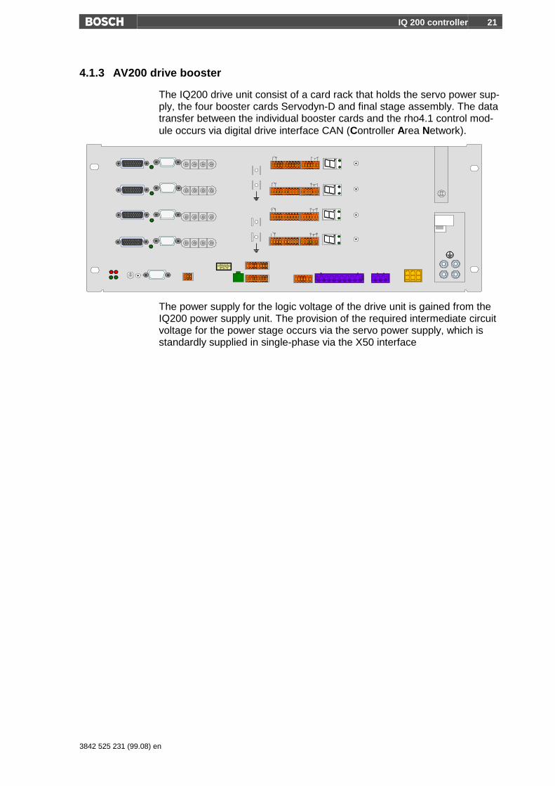
4.1.3 AV200 drive booster
The IQ200 drive unit consist of a card rack that holds the servo power sup-ply, the four booster cards Servodyn-D and final stage assembly. The datatransfer between the individual booster cards and the rho4.1 control mod-ule occurs via digital drive interface CAN (Controller Area Network).
The power supply for the logic voltage of the drive unit is gained from theIQ200 power supply unit. The provision of the required intermediate circuitvoltage for the power stage occurs via the servo power supply, which isstandardly supplied in single-phase via the X50 interface
22 IQ 200 controller
3842 525 231 (99.07) de
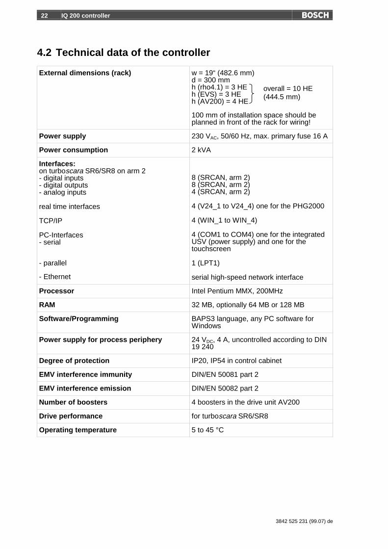
4.2 Technical data of the controller
External dimensions (rack) w = 19“ (482.6 mm)d = 300 mmh (rho4.1) = 3 HEh (EVS) = 3 HEh (AV200) = 4 HE
100 mm of installation space should beplanned in front of the rack for wiring!
Power supply 230 VAC, 50/60 Hz, max. primary fuse 16 A
Power consumption 2 kVA
Interfaces:on turboscara SR6/SR8 on arm 2- digital inputs- digital outputs- analog inputs
real time interfaces
TCP/IP
PC-Interfaces- serial
- parallel
- Ethernet
8 (SRCAN, arm 2)8 (SRCAN, arm 2)4 (SRCAN, arm 2)
4 (V24_1 to V24_4) one for the PHG2000
4 (WIN_1 to WIN_4)
4 (COM1 to COM4) one for the integratedUSV (power supply) and one for thetouchscreen
1 (LPT1)
serial high-speed network interface
Processor Intel Pentium MMX, 200MHz
RAM 32 MB, optionally 64 MB or 128 MB
Software/Programming BAPS3 language, any PC software forWindows
Power supply for process periphery 24 VDC, 4 A, uncontrolled according to DIN19 240
Degree of protection IP20, IP54 in control cabinet
EMV interference immunity DIN/EN 50081 part 2
EMV interference emission DIN/EN 50082 part 2
Number of boosters 4 boosters in the drive unit AV200
Drive performance for turboscara SR6/SR8
Operating temperature 5 to 45 °C
overall = 10 HE(444.5 mm)

IQ 200 controller 23
3842 525 231 (99.08) en
Notes........................................................................................................................................................................................................................................................................................................................................................................................................................................................................................................................................................................................................................................................................................................................................................................................................................................................................................................................................................................................................................................................................................................................................................................................................................................................................................................................................................................................................................................................................................................................................................................................................................................................................................................................................................................................................................................................................................................................................................................................................................................................................................................................................................................................................................................................................................................................................................................................

24 Accessories
3842 525 231 (99.07) de
5 Accessories
5.1 turboscara SR6/SR8
5.1.1 Tool Connector
The Tool Connector (TC) has user I/Os andeven 5/2 directional control compressed airvalves directly on the gripper flange. The ca-bles/lines are completely integrated into the ro-bot. The TC enables ultra-short cycle times viathe short supply line between the valves and thegripper. It also enables a simple and fast appli-cation and start-up via the clear installation pro-cedure.
The TC has 5 inputs and 8 outputs. The user installation guides the 8 in-puts and 8 outputs through the turboscara’s sleeve down to the TC. 5 in-puts and 8 outputs are connected directly to the TC. The 3 additional inputsare available on a separate plug.
The mounting of the Bosch gripper PPG11/21/31 is achieved very quicklywith intermediate flanges.
Technical data
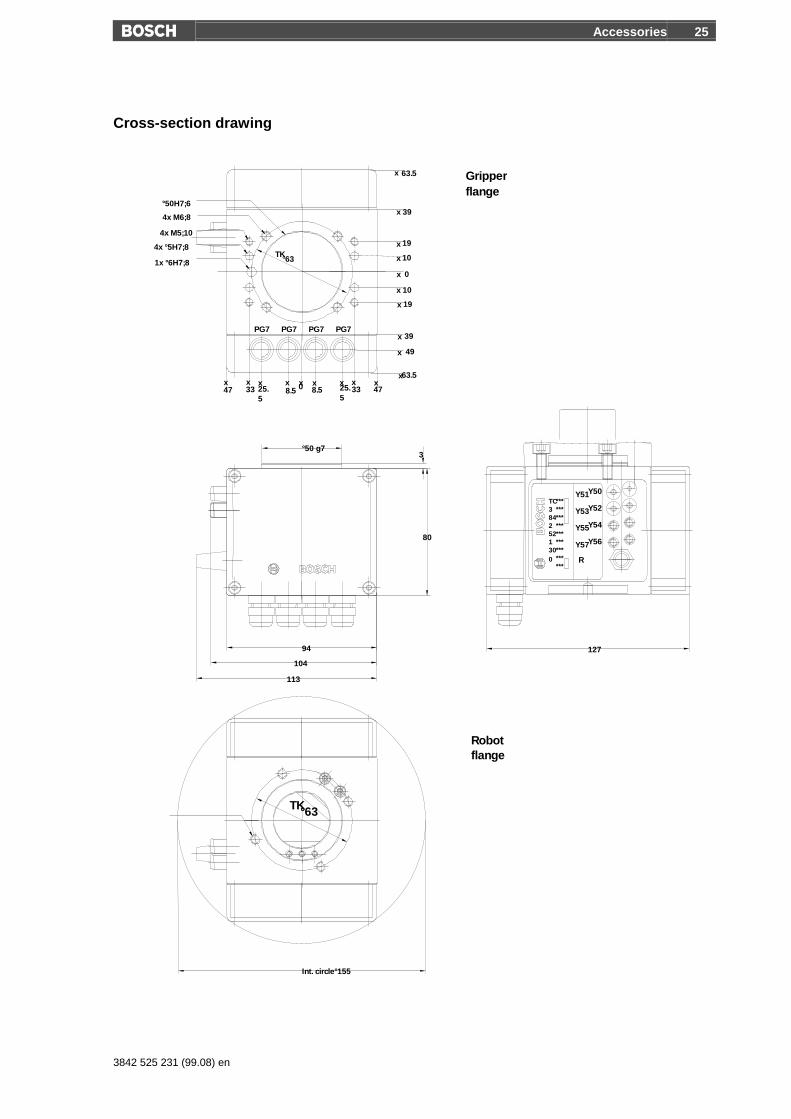
Housing dimensions 94×78×80 mm
Overall dimensions 94×127×80 mm
Interference circle diameter 155 mm
Weight 0.85 kg
Power supply 24 V, 0 V,PE
Max. current 2 A
Degree of protection IP54
Outputs 8
Inputs 5
Operating pressure 1.5 to 7 bar
Compressed air filtered 5 µm
Rated flow per valve at 6 bars 96 l/min
Valve switching response time < 15 ms
Switching frequency 5 Hz
Accessories 25
3842 525 231 (99.08) en
Cross-section drawing
0
80
°50 g7
Y56
Y54
R
Y57
Y55
Y52
Y50Y51
Y53TC3842521300
***************************
flangeGripper
flangeRobot
x 19
x63.5
49x
x 39
x 10
x 0
x 10
x 19
x 39
x 63.5
8.525.5
xx47
x33
xx478.5 25.
533
x x xx
1x °6H7;8
4x °5H7;8
4x M5;10
4x M6;8
°50H7;6
°63TK
Int. circle°155
12794
104
113
3
TK°63
PG7 PG7 PG7 PG7

26 Accessories
3842 525 231 (99.07) de
5.1.2 Pneumatic parallel gripper
2-finger parallel gripperTypes PPG11, PPG21, PPG31
• Directly connectable to the turboscaraSR6/SR8 via an intermediate flange
• Very compact due to the integrated drivein the housing
• Very light due to the use of high tensilealuminium
• Gripping power spring lock when used as external gripper
• High gripping power due to wedge hook kinematics
• Good guide characteristics via flat guiding
• Centric and parallel gripper motion with fixed gripping jaws
• Air connection and gripper mount from 3 sides
Technical data
Actuation pneumatic
Compressed air filtered (10 µm) and oiled
Operating pressure min. 5 bar, max. 6,5 bar
Installation position any
Operating temperature 5 to 60 °C
Repetition accuracy approx. 0,05 mm
Type A B C D
mm mm mm mm
PPG11 64 36 56 52
PPG21 80 42 69 64
PPG31 100 50 80.5 80
Type Mass Lift perjaw
Weight of work-piece
Gripping power lock throughspring (standard value)
kg mm kg min. N max. N
PPG11 0.62 6 1.2 90 170
PPG21 1.11 8 1.8 150 250
PPG31 1.74 10 2.8 210 330

Accessories 27
3842 525 231 (99.08) en
5.2 IQ 200 controller
5.2.1 Operating block
PROG RESET
TEST
EMERG STOPINIT ACTIVEERRORDOOR RELEASE
The operating block with its switches and LED enables the operation of thebasic functions of the IQ200:
• Mode selection (automatic / hand / test operation)
• Start, stop and continuation of user programs
• On and off switching of the drive performance
• Reset
• Display of operating conditions
• Emergency switch
Installation dimensions (Door section)
48
201
103.5∅4 4
52
207

28 Accessories
3842 525 231 (99.07) de
5.2.2 Touchscreen BF200T
Touchscreen for programming, operating and visualising
The BF200T touchscreen performs all display functions required for pro-gramming, operations and diagnosis.
Equipment
• 10.4" TFT colour display
• 600 x 480 pixels
• Touchmouse driver
• Touchscreen controller
Installation dimensions
226+0.5
326+0.5∅4 6
238
338
119
169
6

Accessories 29
3842 525 231 (99.08) en
5.2.3 PHG2000 hand-held programming device
BAPS3 programs can be constructed and tested directly on the controllerwith the PHG2000. Furthermore, data from an application program can bedisplayed or inquired. The following operational functions can also be car-ried out:
• Travel to the reference points
• Manual movement of the axes
• Teaching of points in the work space
• Diagnosis
• Parameterisation and much more
The PHG2000 is equipped with its own microprocessor. You can makeyour own masks and menu levels. As a further characteristic the rho4.1system variables can be accessed with the PHG2000.
The PHG2000 is also equipped with a two-channel emergency switch anda two-channel confirmation button. When motion functions are performedin manual mode, the confirmation button is monitored additionally by thereal time operating system. With corresponding additional measures it isthus possible for the robot to be moved in the test mode even when theprotective door is open.
If the PHG2000 is not connected, it must be removed from the systemor its emergency switch will not function.
30 Accessories
3842 525 231 (99.07) de
5.2.4 Software
The following software are available as accessories
• ROPS4/Online
• DDE-Server 4
• WinSPS
• WinDP / WinCAN
ROPS4/Online
ROPS4/Online enables the creating, testing, and archiving of programs forthe rho4 controller. The program can be run with Windows95 or Win-dowsNT. The use of a mouse is not required, but is recommended, sincethis makes it more comfortable for the operator. ROPS4 is protectedagainst unauthorised copying. A software license is required to operateROPS4.
ROPS4/Online has the following functions:
• BAPS plus: A structure-oriented program system with which sequencingprograms can be quickly and easily created, documented and tested intop-down design. The important advantage of this expansion lies in theautomatic code generation and in the possibility to observe the process.The program course is arranged in the form of a program course planconstructed of picture symbols.
• Machine parameter converter: Readable and alterable ASCII files *.ampcan be made from machine parameter files *.bin with the help of theconverter. Another part of the converter alters ASCII files into machineparameter files which can then be loaded into the controller.
• Integrated BAPS translator translates the created motion programs withhelp of the ASCII editor.
• Program archiving (load, save, list, delete, name etc.)
• Remote control functions: program start, display of axis position, I/Ostatus etc.
• Coupling functions: transfer of files from/to rho4, connection to the rho4via serial interface or TCP/IP.
• Offline/online points editor.
• Process functions: process selection, process start, process stop etc.

Accessories 31
3842 525 231 (99.08) en
DDE Server4
The DDE Server4 connects rho4.1 to Windows.
The software package ROPS4 offers many functions to communicate withthe rho4 controller: data transfer, process and status functions. In the fol-lowing they are also called online functions. These services are put to-gether in a program package equipped with a comfortable graphical userinterface and can be run with Windows95 and WindowsNT.
A function library with a normalised interface is required to give the user thepossibility to integrate the online functions into his own user interface orinto the rho4 with Windows remote control, i.e. without the use of the PC.
For this integration, MS Windows has inter-process communication Dy-namic Data Exchange. In order to exchange data between two Windowsapplications, one of them must serve as client (e.g. the user interface) andthe other as server (DDE-Server4).
The DDE Server4 offers several services for this communication which canbe used by the client. These services are used to set up connections, ex-change data, monitor, execute and much more. This data exchange can beseparated into one-time transfers (e.g. process start) and dynamic data ex-changes (e.g. axis display). All functions for the process communicationare located in the library DDEML (Dynamic Data Exchange ManagementLibrary). In general the client and server can only communicate via thesefunctions.
WinSPS
The integrated software SPS (PCL) can be programmed with WinSPS. Asa future programming tool WinSPS offers the famous Windows Look &Feel for instruction lists (AWL), operation language (AS), function plan(FUP) and contact plan (KOP).
Optionally, a WinSPS license can be directly ordered when ordering therobot system. This license contains:
• Basic WinSPS license
• License for the PCL
• License for the central programming (enables the SPS programming onanother computer that is connected with the rho4.1)
WinDP/ WinCAN
WinDP or WinCAN serve to configure the inputs and outputs which areconnected to the optional PROFIBUS DP master card or CANopen card.
32 Accessories
3842 525 231 (99.07) de
GateWay
GateWay is part of the standard scope of delivery.
GateWay is a Windows application for Windows95 or WindowsNT. Itserves the TCP/IP communication between the rho4.1 and all external cli-ents and Servers.
IP address and port number
A TCP/IP address consist of 2 components: the IP address of the computer(host) and a port number. The IP address is the world wide definitive ad-dress of the PC. The address is comparable to a normal house addresswith country, city, street and house number. The port number is the num-ber of a server or client on the computer. This is comparable to the nameof the person at the address. The port numbers 6000 to 6200 and 5000 to5200 are reserved for Bosch.
Establishing a connection
GateWay can be started after the controller is up and running.
During the initialisation GateWay builds a TCP/IP link to the correspondingserver for all adjusted connections in the file GateWay.ini. At the same timea GateWay server branch is started for each of these connections. It isavailable for the linking of a client. Since GateWay runs under the Win-dows part of the PC, the IP address is the IP address of the physicalEthernet card.
5.2.5 Licensing the software
Software requiring a license:
• ROPS4/Online
• WinSPS (Basic package + PCL + central programming)
• DDE-Server4
• WinDP / WinCAN
As an option, software licences can be ordered directly with the robot sys-tem.
You can also order the individual software licences from the AST depart-ment (drive and controller technology). The software installation data arealready in the rho4.1. You can find a fax form under the menu item ‘Li-cense application‘ of each software. Using this fax form, you can apply forthe license, see point 7.3.6.
Accessories 33
3842 525 231 (99.08) en
5.2.6 I/O-Module
You will find more information on I/O expansion in paragraph 6.7.
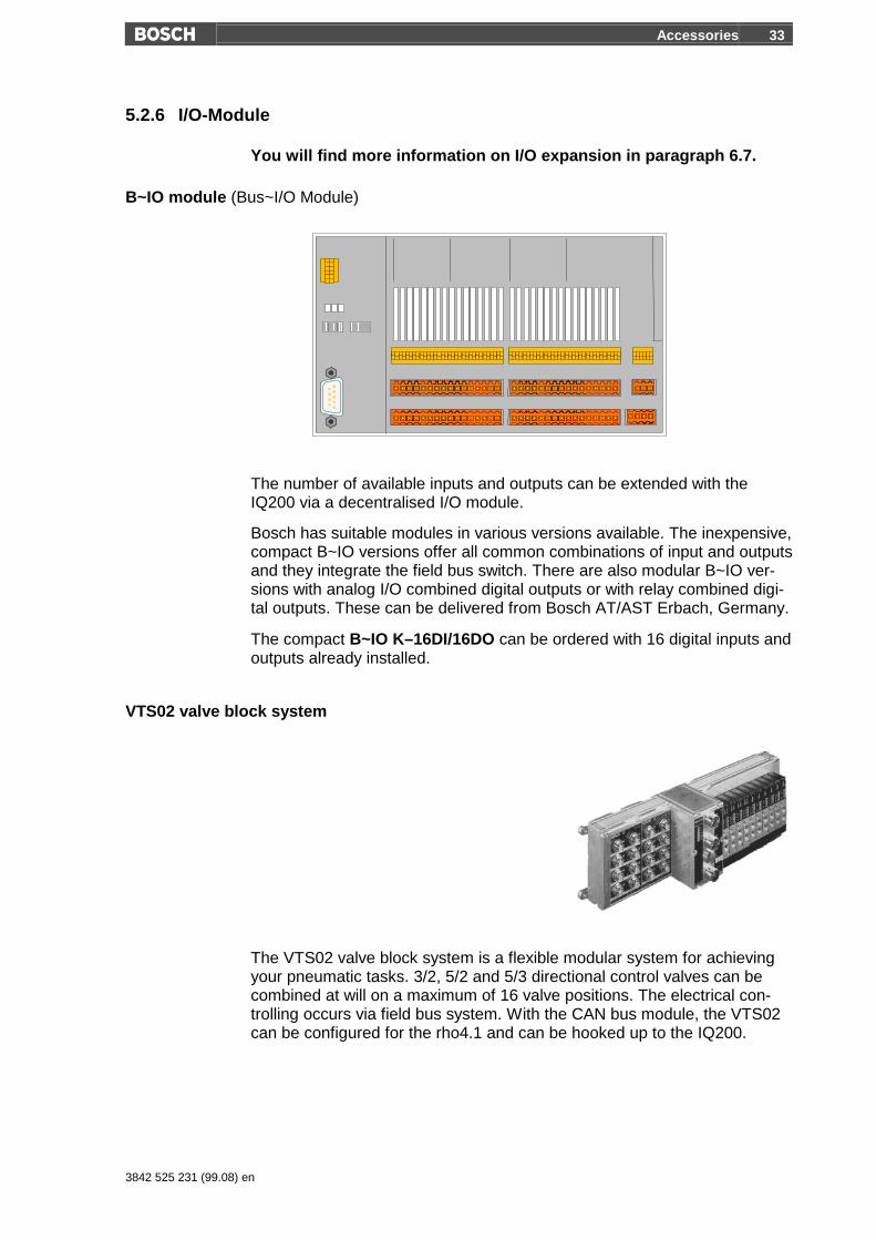
B~IO module (Bus~I/O Module)
The number of available inputs and outputs can be extended with theIQ200 via a decentralised I/O module.
Bosch has suitable modules in various versions available. The inexpensive,compact B~IO versions offer all common combinations of input and outputsand they integrate the field bus switch. There are also modular B~IO ver-sions with analog I/O combined digital outputs or with relay combined digi-tal outputs. These can be delivered from Bosch AT/AST Erbach, Germany.
The compact B~IO K–16DI/16DO can be ordered with 16 digital inputs andoutputs already installed.
VTS02 valve block system
The VTS02 valve block system is a flexible modular system for achievingyour pneumatic tasks. 3/2, 5/2 and 5/3 directional control valves can becombined at will on a maximum of 16 valve positions. The electrical con-trolling occurs via field bus system. With the CAN bus module, the VTS02can be configured for the rho4.1 and can be hooked up to the IQ200.
34 Accessories
3842 525 231 (99.07) de
5.2.7 Further bus connections
Additional bus connections can be achieved with optional plug-in cards:
PROFIBUS DP master card
PROFIBUS DP master card is a plug-in card that is built directly into therho4.1 and is delivered already configured. With the PROFIBUS DP mastercard it is possible to connect I/O islands as PROFIBUS-DP slaves to thecontroller. The configuration of these modules is programmed with WinDP.The evaluation of the signals occurs in the PLC program.
CANopen
The CANopen plug-in card is built directly into the rho4.1 and is deliveredalready configured. With this card it is possible to connect CANopen I/Oislands to the controller. The configuration of these modules is pro-grammed with WinCAN. The evaluation of the signals occurs in the PLCprogram.
InterbusS (in the making)
The InterbusS plug-in card is build directly into the rho4.1 and is deliveredalready configured. With this card it is possible to connect InterbusS I/Oislands to the controller (in the making).
The B~IO modules can be set into the corresponding versions as I/O is-lands.
Accessories 35
3842 525 231 (99.08) en
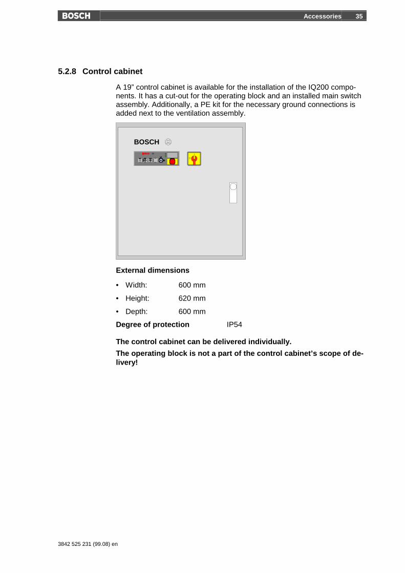
5.2.8 Control cabinet
A 19” control cabinet is available for the installation of the IQ200 compo-nents. It has a cut-out for the operating block and an installed main switchassembly. Additionally, a PE kit for the necessary ground connections isadded next to the ventilation assembly.
BOSCH
External dimensions
• Width: 600 mm
• Height: 620 mm
• Depth: 600 mm
Degree of protection IP54
The control cabinet can be delivered individually.
The operating block is not a part of the control cabinet’s scope of de-livery!
36 Layout criteria
3842 525 231 (99.07) de
6 Layout criteria
6.1 Load capacity
Load is defined as all attached mass (e.g. gripper, workpiece, tool) on theflange surface as well as attached periphery on arm 2.
The sum of all individual masses must not exceed the permitted over-all load!
Load capacity ½ 5 or 8 kg
6.2 Mass moment of inertia
The effective mass moment of inertia around the fourth axis is a combina-tion of the moments of inertia of the individual masses attached to theflange surface.
Under no circumstances is the maximum value to be exceed!
Maximum mass moment of inertia ½ 1000 kg cm2
6.3 Reaction forces
The permissible effecting forces on the robot are dependant on variousfactors of influence: duration of effect, direction of force, and the distancefrom the flange’s upper position.
Exceeding the given values can lead to mechanical or thermal over-load of the robot!
Maximum horizontal force ½ 150 N
Maximum vertical force ½ 300 N
Layout criteria 37
3842 525 231 (99.08) en
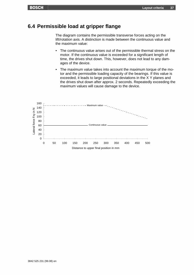
6.4 Permissible load at gripper flange
The diagram contains the permissible transverse forces acting on thelift/rotation axis. A distinction is made between the continuous value andthe maximum value:
• The continuous value arises out of the permissible thermal stress on themotor. If the continuous value is exceeded for a significant length oftime, the drives shut down. This, however, does not lead to any dam-ages of the device.
• The maximum value takes into account the maximum torque of the mo-tor and the permissible loading capacity of the bearings. If this value isexceeded, it leads to large positional deviations in the X Y planes andthe drives shut down after approx. 2 seconds. Repeatedly exceeding themaximum values will cause damage to the device.
0
20
40
60
80
100
120
140
160
0 50 100 150 200 250 300 350 400 450 500
Distance to upper final position in mm
Late
ral f
orce
Fxy
in N
Maximum value
Continuous value

38 Layout criteria
3842 525 231 (99.07) de
6.5 Working area
The working area shown in the dimensioned diagrams is valid for the ToolCenter Point: the center of the flange surface. During the layout, take intoconsideration that attachments and bulky tools do not cause collisions withthe robot stand. If this should be the case, you can limit the working areavia the software limit switch.
Observe the working area limits when making constructions!
6.5.1 Planning sheet for the SR6
-600 6005004003002001000-100-200-300-400-500 700
-600
600
500
400
300
200
100
0
-100
-200
-300
-400
-500
700
-700
Swivel angle: Lift: M 1 : 10
Axis 1: ± 140° Axis 3: 200 mm
Axis 2: ± 150°
Axis 4: ± 180°

Layout criteria 39
3842 525 231 (99.08) en
6.5.2 Planning sheet for the SR8
-600
600
500
400
300
200
100
0
-100
-200
-300
-400
-500
700
-700
800
-900
-800
900
-600 6005004003002001000-100-200-300-400-500 700-700-800 800
Swivel angle: Lift: M 1 : 10
Axis 1: ± 140° Axis 3: 200 mm
Axis 2: ± 155°
Axis 4: ± 180°

40 Layout criteria
3842 525 231 (99.07) de
6.6 Cycle time
The adherence of the required cycle time can be determined with help ofthe diagrams on the following pages. When making determinations, do notforget that the cycle time is a combination of the travelling time and theprocess times (e.g. gripping times) and that not every process allows forthe maximum acceleration and velocity. When a swivel arm robots is inmotion, very high angle accelerations can occur which can cause, for ex-ample, the workpiece to be pulled loose from the gripper.
6.6.1 Cycle time determination
Procedure
• Determine the initial position and final position for each individual axisand from that, the distance travelled.
• Read off the corresponding travelling time from the diagrams for thedetermined path distance. When the motions of several axis overlayeach other, the longest travelling time is valid.
• Determine the total travelling time by adding together the travel times inthe sequence.
• Now add 0.06 s positioning time for each exact position to be moved to,e.g. with BAPS command ,Move to point‘.
• Finally, only the process times (gripping time, etc.) must be taken intoaccount. Typical process times, e.g. time to close the gripper, lie be-tween 0.15 and 0.3 seconds. This value comprises the reaction time ofthe valve, the build up of pressure up to the gripper, and the movementof the gripper. Since gripper processes are frequent, there is a largepotential for optimisation here. For example, by arranging the valves atthe gripper (installation of the Tool Connectors on the robot flange). Theuse of vacuum suction technology proves to be advantageous, sinceonce the vacuum has be activated, the process times for the gripper arealmost negligible.

Layout criteria 41
3842 525 231 (99.08) en
• A further possibility to save cycle time exist with spatial passing. Thenormal pick-and-place procedure (see figure) has the following affect onthe movement process. As a result of the ‘move via’ command, thepoints P2 and P3 will be passed within the zone defined by R.
In practice, the driving time of the third axis is usually responsible for howmuch driving time is saved. In this case the following can be generalised:depending on lift and defined passing area, a saving of up to 50% of thedrive time of the third axis can be achieved. When determining the passingarea, existing interferences (edges of pallets, boxes, crates) in the pathmust be taken into account!
This procedure permits a rough estimation. However, valid and bind-ing statements on cycle times can only be made after testing underrealistic conditions, since it is often the peripheral processes that cansignificantly influence the cycle time of the entire station.

42 Layout criteria
3842 525 231 (99.07) de
6.6.2 Cycle time diagrams
turboscara SR6
1,00
10,00
100,00
1000,00
0,000 0,100 0,200 0,300 0,400 0,500 0,600 0,700[s]
[°] or [mm]
Axis 1 [°] Axis 2 [°] Axis 4 [°] Axis 3 Ø25 [mm] Axis 3 Ø20 [mm]
turboscara SR8
1,00
10,00
100,00
1000,00
0,000 0,100 0,200 0,300 0,400 0,500 0,600 0,700
[s]
[°] or [mm]
Axis 1 [°] Axis 2 [°] Axis 4 [°] Axis 3 Ø25 [mm] Axis 3 Ø20 [mm]
Layout criteria 43
3842 525 231 (99.08) en
6.7 I/O expansion
The standard robot system provides the following configuration:
• 8 digital inputs
• 8 digital outputs
• 4 analog inputs (10 bit in SPS programs, 8 bit in BAPS programs)
16I and 16O are additional provided with the optional ”B~IO module16I/16O in the controller“.
The I/O configuration can be further expanded by the customer (e.g. fur-ther B~IO modules, see product program AST, drive and controlling tech-nology):
• The maximum number of CAN I/Os in the SPS program is 48 bytes in-puts and 48 bytes outputs, whereby a digital input or output takes up 1bit and an analog input or output takes up 2 bytes.
• Up to 199 inputs and 199 outputs or 8 analog inputs and 16 analog out-puts can be addressed in the BAPS program.The following are standard in the SPS program for BAPS programs:
- 199 CAN I/O for BAPS- 4 analog inputs on the SRCAN modules in arm 2, filtered to 8 Bit.
• When making a layout with a larger number of I/Os, the configuration ofthe B~IO modules must be taken into account (maximum number ofjunctions on the CAN2).Please contact your system integrator when performing this.
• When making configurations with an additional bus card (PROFIBUS-DP master, CANopen, InterbusS (in the making)), an additional 16 byteI/O is available. This number can be expanded by upgrading the PCLversion from PCL-S to PCL-L or PCL-X :
- PCL-S: 16 byte I/O 16K instructions in AWL- PCL-L: 256 byte I/O 64K instructions in AWL- PCL-X: 8192 byte I/O 128K instructions in AWL
The configuration of the modules occurs with WinDP, the evaluationwith WinSPS.
44 Layout criteria
3842 525 231 (99.07) de
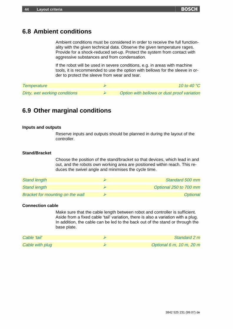
6.8 Ambient conditions
Ambient conditions must be considered in order to receive the full function-ality with the given technical data. Observe the given temperature rages.Provide for a shock-reduced set-up. Protect the system from contact withaggressive substances and from condensation.
If the robot will be used in severe conditions, e.g. in areas with machinetools, it is recommended to use the option with bellows for the sleeve in or-der to protect the sleeve from wear and tear.
Temperature ½ 10 to 40 °C
Dirty, wet working conditions ½ Option with bellows or dust proof variation
6.9 Other marginal conditions
Inputs and outputs
Reserve inputs and outputs should be planned in during the layout of thecontroller.
Stand/Bracket
Choose the position of the stand/bracket so that devices, which lead in andout, and the robots own working area are positioned within reach. This re-duces the swivel angle and minimises the cycle time.
Stand length ½ Standard 500 mm
Stand length ½ Optional 250 to 700 mm
Bracket for mounting on the wall ½ Optional
Connection cable
Make sure that the cable length between robot and controller is sufficient.Aside from a fixed cable ‘tail’ variation, there is also a variation with a plug.In addition, the cable can be led to the back out of the stand or through thebase plate.
Cable ‘tail’ ½ Standard 2 m
Cable with plug ½ Optional 6 m, 10 m, 20 m

Layout criteria 45
3842 525 231 (99.08) en
User installation
Interfaces for user installation are offered as standard in the installationarea of arm 2. If these are needed on the gripper flange, this can beachieved via an optional installation in the sealed cable pipe and via thesleeve up to the gripper flange.
Interfaces in Arm 2 ½ Standard
Empty pipe without cable ½ Optional
Installation up to gripper flange ½ Optional

46 Ordering
3842 525 231 (99.07) de
7 OrderingYou can use the following sheets to order a Bosch robot system. Theycontain all standard components, options, accessory parts and documen-tation.
7.1 Notes on ordering
• Mark the desired components in the column to the right with an X.
• In case you would like to order a variation of the standard, mark an X inthe box for ‘with the fixed options listed below’ and then choose the op-tions in the ‘options’ table with an X.
• If a choice of measurements is given, choose the desired values.
7.2 Example
Robots Order number
turboscara SR6, Standard 3842 999 835
turboscara SR6 with the fixed options listed below
turboscara SR8, Standard 3842 999 836
turboscara SR8 with the fixed options listed below X
turboscara SR6 dust proof
SR6 dust proof with the fixed options listed below
3842 999 849
turboscara SR8 dust proof
SR8 dust proof with the fixed options listed below
3842 999 850
Options for the turboscara SR6 / SR8 Dimensions
Stand length 250, 300, 350, 400, 450, 550, 600, 650, 700 350 X
Bracket instead of stand
Sleeve with ∅ 25 mm, Lift 200 mm, 400 mm 400 X
Lift 600 mm (only with agreement!)
Connecting cable with plug, 6 m, 10 m, 20 m 10 X
Empty pipe up to sleeve for the user installation (not with dust proof!) X
Installation kit up to flange
Bellows around sleeve ( already included with dust proof!)
Ordering 47
3842 525 231 (99.08) en
7.3 Order forms
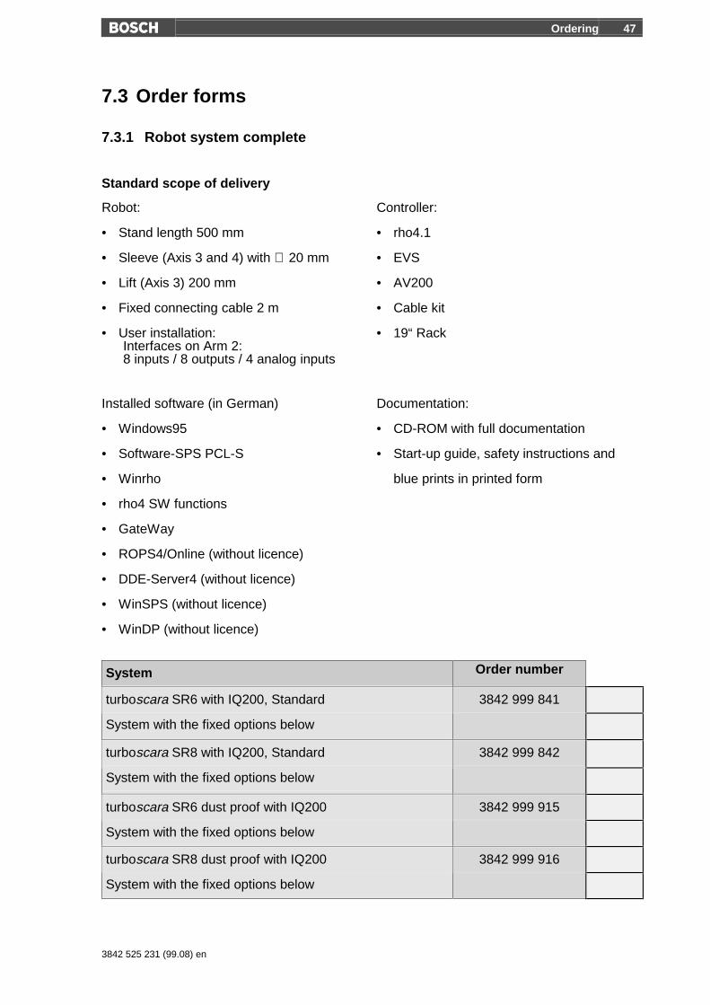
7.3.1 Robot system complete
Standard scope of delivery
Robot: Controller:
• Stand length 500 mm • rho4.1
• Sleeve (Axis 3 and 4) with ∅ 20 mm • EVS
• Lift (Axis 3) 200 mm • AV200
• Fixed connecting cable 2 m • Cable kit
• User installation:Interfaces on Arm 2:8 inputs / 8 outputs / 4 analog inputs
• 19“ Rack
Installed software (in German) Documentation:
• Windows95 • CD-ROM with full documentation
• Software-SPS PCL-S • Start-up guide, safety instructions and
• Winrho blue prints in printed form
• rho4 SW functions
• GateWay
• ROPS4/Online (without licence)
• DDE-Server4 (without licence)
• WinSPS (without licence)
• WinDP (without licence)
System Order number
turboscara SR6 with IQ200, Standard
System with the fixed options below
3842 999 841
turboscara SR8 with IQ200, Standard
System with the fixed options below
3842 999 842
turboscara SR6 dust proof with IQ200
System with the fixed options below
3842 999 915
turboscara SR8 dust proof with IQ200
System with the fixed options below
3842 999 916

48 Ordering
3842 525 231 (99.07) de
7.3.2 Swivel arm robot turboscara SR6/SR8
Standard scope of delivery (only robot mechanics)
• Stand length 500 mm
• Sleeve (Axis 3 and 4) with ∅ 20 mm
• Lift (Axis 3) 200 mm
• Fixed connecting cable 2 m
• User installation: Interfaces on arm 2
Robot Order number
turboscara SR6, Standard 3842 999 835
turboscara SR6 with the fixed options below
turboscara SR8, Standard 3842 999 836
turboscara SR8 with the fixed options below
turboscara SR6 dust proof
SR6 dust proof with the fixed options below
3842 999 849
turboscara SR8 dust proof
SR8 dust proof with the fixed options below
3842 999 850

Ordering 49
3842 525 231 (99.08) en
7.3.3 Options
Options turboscara SR6/SR8 Dimensions
Stand length 250, 300, 350, 400, 450, 550, 600, 650, 700
Bracket instead of stand
Sleeve with ∅ 25 mm, Lift 200 mm, 400 mm
Lift 600 mm (only with agreement!)
Connecting cable with plug, 6 m, 10 m, 20 m
Empty pipe up to sleeve for the user installation (not with dust proof!)
Installation kit up to flange (for Tool Connector)
Bellows around sleeve (already included with dust proof!)
Driveless teaching through button for brakes axis 3/4 (in the making)
IQ200 Options
Operating block
Control cabinet with main switch (order also operating block!)
B~IO compact module 16E/16A, installed, wired, configured, with plugs
Touchscreen BF200T includes 10 m cable, loosely enclosed
RAM expansion from 32 MB to 64 MB or 128 MB 64MB 128MB
WindowsNT instead of Windows95 (RAM expansion to a minimum of 64 MBnecessary!)
Additional bus card
Profibus DP Master
CANOpen
InterbusS (in the making)
Software licences:
ROPS4/Online
WinSPS (Basic package + PCL + central programming)
DDE-Server4
WinDP
Hardlock (dongle) for transferring of software licences
(the dongle is empty when delivered)
English language (Windows and installed software)
The EVS, rho4.1, AV200, operating block and main switch are already installed and tested in orders withcontrol cabinet and operating block.
50 Ordering
3842 525 231 (99.07) de
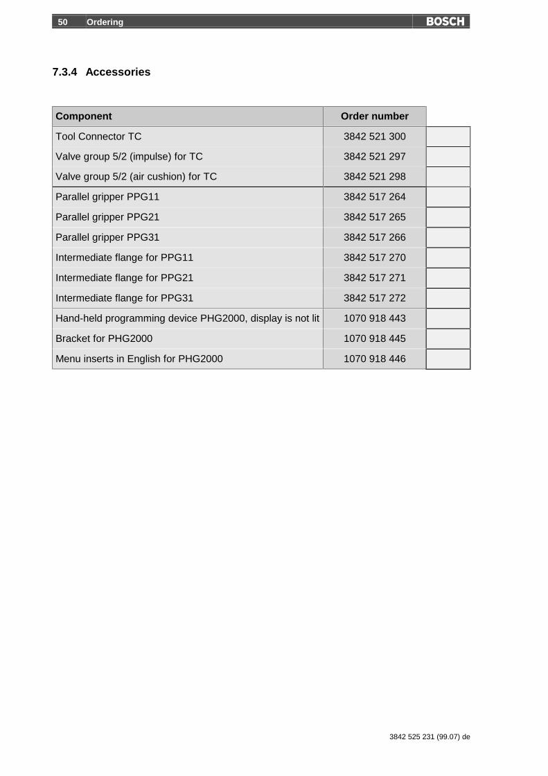
7.3.4 Accessories
Component Order number
Tool Connector TC 3842 521 300
Valve group 5/2 (impulse) for TC 3842 521 297
Valve group 5/2 (air cushion) for TC 3842 521 298
Parallel gripper PPG11 3842 517 264
Parallel gripper PPG21 3842 517 265
Parallel gripper PPG31 3842 517 266
Intermediate flange for PPG11 3842 517 270
Intermediate flange for PPG21 3842 517 271
Intermediate flange for PPG31 3842 517 272
Hand-held programming device PHG2000, display is not lit 1070 918 443
Bracket for PHG2000 1070 918 445
Menu inserts in English for PHG2000 1070 918 446

Ordering 51
3842 525 231 (99.08) en
7.3.5 Documentation
The robot’s standard scope of delivery includes a slipcase with the start-upguide – a short introduction to working with the robot -, the safety instruc-tions and the circuit diagram. In addition, it contains a CD-ROM that has,aside from all manuals listed below in German and in English, CAD data,planning instruction, and information on Bosch and its automation technol-ogy division.
The essential chapters and current changes of this CD-ROM can also befound via the Internet under the following address:http://www.bosch.de/at/rhs .
German/English
System Order number
Slipcase 3842 524 317
CD-ROM 3842 524 619
Start-up guide German 3842 524 306
Start-up guide English 3842 525 128
For additional orders of documentation write a fax:
Robert Bosch GmbH
AT/VWM1
Fax 07 11/ 8 11 - 78 95
The entire manual (CD-ROM) contains the following manuals:
Ordering number
German
Mechanik 3842 524 311
Robotersteuerung IQ 200 3842 524 313
Sicherheitshinweise 3842 524 315
BAPS3 Kurzbeschreibung 1070 072 412
BAPS3 Programmieranleitung 1070 072 413
Maschinenparameter 1070 072 414
Signalbeschreibung 1070 072 415
Statusmeldungen und Warnungen 1070 072 417

52 Ordering
3842 525 231 (99.07) de
DLL-Bibliothek 1070 072 418
Steuerungsfunktionen 1070 072 420
PHG2000 1070 072 421
BAPS plus 1070 072 422
ROPS4/Online 1070 072 423
DDE-Server4 1070 072 433
Systembeschreibung 1070 072 434
English
Mechanic 3842 524 378
IQ 200 Robot Control System 3842 525 379
Safety instructions 3842 524 315
BAPS3 Short description 1070 072 177
BAPS3 Programming manual 1070 072 178
Machine parameters 1070 072 175
Signal descriptions 1070 072 182
Status messages and warnings 1070 072 181
DLL-Library 1070 072 176
Control functions 1070 072 179
PHG2000 1070 072 183
BAPS plus 1070 072 187
ROPS4/Online 1070 072 180
DDE-Server4 1070 072 184
System description 1070 072 185
Ordering 53
3842 525 231 (99.08) en
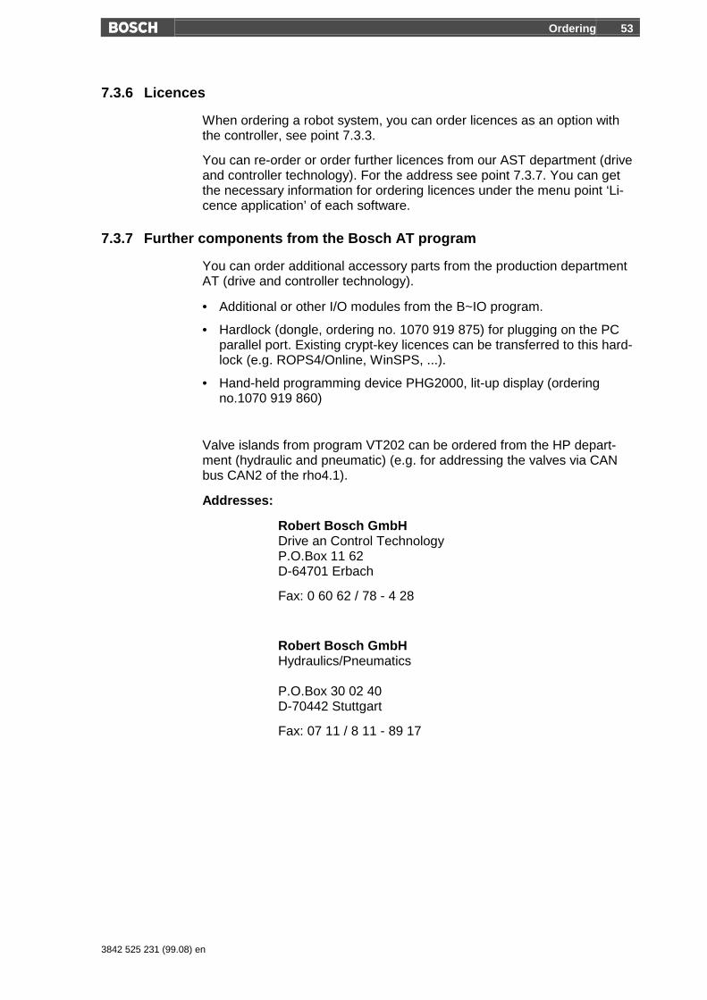
7.3.6 Licences
When ordering a robot system, you can order licences as an option withthe controller, see point 7.3.3.
You can re-order or order further licences from our AST department (driveand controller technology). For the address see point 7.3.7. You can getthe necessary information for ordering licences under the menu point ‘Li-cence application’ of each software.
7.3.7 Further components from the Bosch AT program
You can order additional accessory parts from the production departmentAT (drive and controller technology).
• Additional or other I/O modules from the B~IO program.
• Hardlock (dongle, ordering no. 1070 919 875) for plugging on the PCparallel port. Existing crypt-key licences can be transferred to this hard-lock (e.g. ROPS4/Online, WinSPS, ...).
• Hand-held programming device PHG2000, lit-up display (orderingno.1070 919 860)
Valve islands from program VT202 can be ordered from the HP depart-ment (hydraulic and pneumatic) (e.g. for addressing the valves via CANbus CAN2 of the rho4.1).
Addresses:
Robert Bosch GmbHDrive an Control TechnologyP.O.Box 11 62D-64701 Erbach
Fax: 0 60 62 / 78 - 4 28
Robert Bosch GmbHHydraulics/Pneumatics
P.O.Box 30 02 40D-70442 Stuttgart
Fax: 07 11 / 8 11 - 89 17

54 Services
3842 525 231 (99.07) de
8 Services
8.1 Automation technology, robot technology division
Robert Bosch GmbH
Automation Technology Division
AT/VRO
Wernerstraße 51
P.O.Box 30 02 07
D 70442 Stuttgart
Tel.: (07 11) 8 11 - 3 15 18
Fax : (07 11) 8 11 - 78 75
8.2 Sales
You will receive full support for your individual applications from our systemintegrators. When needed, they will lay out the complete system, programthe robots and run systems for you.
Due to their many years of experience with Bosch robots, our system inte-grators are the right people for your needs.
You will find the Bosch sales partner nearest to you on the back side of thisplanning manual.
If you have any questions, please do not hesitate to call us. We are at yourservice!

Services 55
3842 525 231 (99.08) en
8.3 Training
Our training center in Erbach, Germany, offers comprehensives courses forbeginners and advanced users of the Bosch robot technology. All coursesemphasise practical application and contain practice blocks, in which origi-nal equipment is used to practice what is learned.
Course Subject Duration
SR6 & SR8 Operation
R4/SR6-B
Operation of the SR6/SR8 robot systems withIQ200 controller.
4 days
SR6 & SR8 Maintenance
SR6-I
Maintenance of SR6/SR8 robot systems withIQ200 controller.
3 days
Advanced programming withBAPS3
R4/SR6-P
Advanced user programming with BAPS3 forrobots with IQ200 controller.
4 days
For detailed information contact the training center at:
Telephone 0 60 62 / 78 - 600 or - 602
Address Robert Bosch GmbHAutomation Technology DivisionDidactic
P.O.Box 11 62D-64701 Erbach
8.4 Hotline
If you have any questions on the turboscara SR6/SR8 robot systems withIQ 200 controller, use our customer hotline at:
Telephone 07 11 / 8 11 - 74 97 or 78 74
Address Robert Bosch GmbHAutomation Technology DivisionAT/VRO
P.O.Box 30 02 20D-70442 Stuttgart

56 Services
3842 525 231 (99.07) de
Notes........................................................................................................................................................................................................................................................................................................................................................................................................................................................................................................................................................................................................................................................................................................................................................................................................................................................................................................................................................................................................................................................................................................................................................................................................................................................................................................................................................................................................................................................................................................................................................................................................................................................................................................................................................................................................................................................................................................................................................................................................................................................................................................................................................................................................................................................................................................................................................................................

Appendix 57
3842 525 231 (99.08) en
9 Appendix
9.1 Accessories from other manufactures
On the following two pages you will find data sheets from the company Bihl+ Wiedemann. These sheets describe the AS-i/CANrho Gateway and theCANrho/PROFIBUS coupler.
The data sheets are only for your information. The individual manu-factures take responsibility for the guarantees of their accessoryparts.
AS-i/CANrho Gateway
Bihl+Wiedemann GmbH · Käfertaler Straße 164 · D-68167 Mannheim · Tel. 0621-33996-0 · Fax. 0621-3392239 · eMail: [email protected] ohne Gewähr www.bihl-wiedemann.de
AS-i Gateway to CANrho
AS-i Master128 Bit DigitalI/O-Module forCANrho
Error diagnosisDirectly at Gateway
Article no. 1173/1174
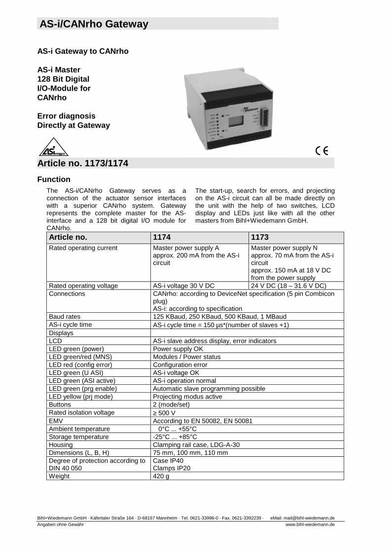
FunctionThe AS-i/CANrho Gateway serves as aconnection of the actuator sensor interfaceswith a superior CANrho system. Gatewayrepresents the complete master for the AS-interface and a 128 bit digital I/O module forCANrho.
The start-up, search for errors, and projectingon the AS-i circuit can all be made directly onthe unit with the help of two switches, LCDdisplay and LEDs just like with all the othermasters from Bihl+Wiedemann GmbH.
Article no. 1174 1173Rated operating current Master power supply A
approx. 200 mA from the AS-icircuit
Master power supply Napprox. 70 mA from the AS-icircuitapprox. 150 mA at 18 V DCfrom the power supply
Rated operating voltage AS-i voltage 30 V DC 24 V DC (18 – 31.6 V DC)Connections CANrho: according to DeviceNet specification (5 pin Combicon
plug)AS-i: according to specification
Baud rates 125 KBaud, 250 KBaud, 500 KBaud, 1 MBaudAS-i cycle time AS-i cycle time = 150 µs*(number of slaves +1)DisplaysLCD AS-i slave address display, error indicatorsLED green (power) Power supply OKLED green/red (MNS) Modules / Power statusLED red (config error) Configuration errorLED green (U ASI) AS-i voltage OKLED green (ASI active) AS-i operation normalLED green (prg enable) Automatic slave programming possibleLED yellow (prj mode) Projecting modus activeButtons 2 (mode/set)Rated isolation voltage ≥ 500 VEMV According to EN 50082, EN 50081Ambient temperature 0°C ... +55°CStorage temperature -25°C ... +85°CHousing Clamping rail case, LDG-A-30Dimensions (L, B, H) 75 mm, 100 mm, 110 mmDegree of protection according toDIN 40 050
Case IP40Clamps IP20
Weight 420 g

CAN/PROFIBUS Coupler
Bihl+Wiedemann GmbH · Käfertaler Straße 164 · D-68167 Mannheim · Tel. 0621-3392723 · Fax. 0621-3392239 · eMail: [email protected] All information subject to change
Connects a CANrho circuitwith a PROFIBUS circuitvia integrated interfaces
easy data exchangebetween CANrho and PROFIBUSvia the internal coupler
Article no. 1184 CANrho/PROFIBUS CouplerArticle no. 1188 CANopen/PROFIBUS CouplerThe CERN/PROFIBUS coupler is the easiestsolution for exchanging data between CERN andPROFIBUS.It is often necessary with large applications toexchange data between the robot controller andanother controller, for example to report operationconditions. In the past, this was commonlyachieved with help from I/Os. The inputs wereconnected with the outputs of the other controllerand vice versa. With help of the CAN-rho/PROFIBUS coupler the cost of wiring and ofthe components are reduced with this task. TheCANrho/PROFIBUS coupler consists of aCANrho slave with 8 byte input data and 8 byte
output data and a PROFIBUS slave with 8 byteinput data and 8 byte output data in a case. Theslave outputs are each connected to inputs of theother slave (CANrho slave output byte 1 withPROFIBUS slave input byte 1).CANrho and PROFIBUS are constructedgalvanically separated.The unit has a one digit display with sevensegments.As long as one of both slaves are not exchangingdata, the second slave has the default value of 0on its inputs.Further CAN protocols e.g. CANopen, etc. can bereceived upon request.
Technical dataArticle no.. 1184Connections PROFIBUS: D-Sub 9 pin
CANrho: 4 pin Combicon plugPROFIBUS-Interface According to DIN 19245 parts 1-
3Baud rates 9,6 KBaud to 12000 KBaud,
automatic recognitionDP functions Illustration of CANrho data as I/O
process data in PROFIBUSFull diagnosis and configurationvia DP master
CANrho Baud rates 125 KBaud, 250 KBaud,500 KBaud, 1 MBaud
Display 1 digit 7 segmentRated operating current < 120 mA at 24VRated operating voltage 24 V DCRated isolation voltage ≥ 500 V DCEMV According to EN 50082, EN
50081Ambient temperature 0°C ... +55°CStorage temperature -25°C ... +85°CCase Clamping rail caseDimensions (L, W, D) 100 mm, 25 mm, 120 mmDegree of protection accordingto DIN 40 050
Case IP20
Weight 120 g
CANrho/PROFIBUSConnection
CANrho/PROFIBUS Koppler
CANrhoCANrho PROFIBUS PROFIBUS
8 Byte A
8 Byte A
8 Byte E
8 Byte E

Appendix 60
3842 525 231 (99.07) en
9.2 Alphabetical Index
AAccessories 24Ambient conditions 44Application support 54AS-i - Bus 58AV200 21
BB~IO-Module 33BAPS translator 30Bellows 6Booster cards 21Bracket 11
CCANopen 34CD-ROM 51Client 32Code generation 30collision 38Components 46Confirmation button 29Connection cable 6, 44Control cabinet 35Cycle time 15, 40
DDDE-Server4 31Documentation 51Drive booster 21Dust proof 7
EEVS 20
FFinal stage 21Flange loads 37Fuse 20
GGateWay 32Gripper 26Gripper flange 12Gripping power 26
HHotline 55
II/O 43
I/O-Module 33Inputs 15, 33Inside radius 14InterbusS 34Interface 22Interface modification controller 16Interfaces 17Interference immunity 22Intermediate flanges 24Interprocess communication 31
LLicence 30Licensing the software 32Lift 14Limit switch 38Load capacity 36Load Capacity 14
MMachine parameter converter 30Machine parameters 19Main switch 35Marginal conditions 44Measurement input 18Microprocessor 16, 17, 29Mode 27Moment of inertia 36Monitor 28
OOperating block 27Operating instructions 51Operating temperature 22Ordering 46Ordering example 46Outputs 15, 33
PPassing 41PHG2000 29Pneumatic lines 15Positioning range 14Power consumption 22Power supply 20Profibus 34, 59Programming 55Programming tools 30Protection type 15Protective door 29
QQuestions 55
RReach 14Reaction forces 36

Appendix 61
3842 525 231 (99.07) en
Reaction moment 14Reaction power 14Repair 55Repetition accuracy 14Reserves 44rho4.1 17ROPS4/Online 30
SScope of delivery 47Server 32Sleeve 6Software 30Software-SPS 31Start-up guide 51Swivel angle 14System integrators 54
TTechnical data
Controller 22Technical Data
Mechanics 14Tool Connector 24Touchscreen 28Training 55
UUser installation 6, 15, 45
VValve block system 33Variations 6Velocities 15View from above 38
WWall assembly 11Weight 15WinCAN 31Windows application 32WinDP 31WinSPS 31Work area 14Working area 38

62 Appendix
3842 525 231 (99.07) en
Notes........................................................................................................................................................................................................................................................................................................................................................................................................................................................................................................................................................................................................................................................................................................................................................................................................................................................................................................................................................................................................................................................................................................................................................................................................................................................................................................................................................................................................................................................................................................................................................................................................................................................................................................................................................................................................................................................................................................................................................................................................................................................................................................................................................................................................................................................................................................................................................................................

Appendix 63
3842 525 231 (99.07) en
Notes........................................................................................................................................................................................................................................................................................................................................................................................................................................................................................................................................................................................................................................................................................................................................................................................................................................................................................................................................................................................................................................................................................................................................................................................................................................................................................................................................................................................................................................................................................................................................................................................................................................................................................................................................................................................................................................................................................................................................................................................................................................................................................................................................................................................................................................................................................................................................................................................

64 Appendix
3842 525 231 (99.07) en
Notes........................................................................................................................................................................................................................................................................................................................................................................................................................................................................................................................................................................................................................................................................................................................................................................................................................................................................................................................................................................................................................................................................................................................................................................................................................................................................................................................................................................................................................................................................................................................................................................................................................................................................................................................................................................................................................................................................................................................................................................................................................................................................................................................................................................................................................................................................................................................................................................................