bosch guide singles - davebarton.com · factory lock relay system this wiring diagram is for cars...
TRANSCRIPT

66ththEDITIONEDITIONDear Installer,
We are excited about our 6th Edition Relay ApplicationGuide! This book is offered FREE any time you place anorder with us.
The Guide has been revised and expanded to 44 pages ofvaluable tech tips featuring circuits designed by leadinginstallers and installation support teams from around thecountry.
With more than 40,000 copies in print, DLC's RelayApplication Guide has become an important reference toolfor installers everywhere. Many positive changes in our lat-est book include a reorganized layout by subject and addi-tional applications for specific vehicles.With a greater vari-ety of circuits to choose from and an easier format to use,we know you'll find time-saving tips and solutions to thoselittle challenges that pop up from time to time.Whetheryou're starting to get your feet wet or are a seasoned vet-eran, the DLC Relay Application Guide will prove to be ahandy tool to have around the shop.
So, to all of those who have contributed to the 6th Editionwith some ingenious applications or technical assistance,our thanks and recognition.
Enjoy,
David Levy
P.S. By the way, if you have a relay application for our nextedition, send it to us, we’d like to here from you.
DAVID LEVYCOMPANY, INC.
66tthhEEDDIITTIIOONN
TA B L E O F C O N T E N T SSECURITYDoor LocksAdding Door Locks-Negative Alarm Trigger. . . . . . . . . . . . . . . . . . . . . 4Adding Door Locks- Positive Alarm Trigger . . . . . 4Negative Pulse Door Locks/Negative Alarm Output . 5Positive Pulse Door Locks/Negative Alarm Output . . 5Reverse Polarity Door Locks/Rest at Ground . . . 6Reverse Polarity Door Locks/Rest Open Circuit (A) . . . . . . . . . . . . . . . . . . . . . . . . . 6Reverse Polarity Door Locks/Rest Open Circuit (B) . . . . . . . . . . . . . . . . . . . . . . . . . 7Interface W/Dual Voltage Systems- 1994 Probe . . 7Door Lock Systems using Vacuum Pump . . . . . . . 8Passenger Door Unlock Bypass Circuit/Universal . . . 8Selective Door Unlock/Negative Pulse System. . . 9Selective Door Unlock/Positive Pulse System . . . 9Selective Door Unlock/Reverse Polarity System . . 10Specialty Door Locks/93 Chrysler LeBaron/Dodge Daytona . . . . . . . . . . . . . . . . . . . . . . . . . 10Specialty Door Locks/(-) Pulse/InterruptDoor Locks- Nissan. . . . . . . . . . . . . . . . . . . . . . 11Specialty Door Locks/1994 Range Rover . . . . . . 11Specialty Door Locks/85-86 Toyota Van . . . . . . . 12Specialty Door Locks/Door Locks- Volvo. . . . . . 12
Starter DisableStarter Kill via Hidden Toggle Switch . . . . . . . . . 13Hidden Toggle Starter Disable/Extra Security . . . 13Ignition Kill Circuit. . . . . . . . . . . . . . . . . . . . . . . 14Safety Starter Cut-off. . . . . . . . . . . . . . . . . . . . . 14Stealth Starter Interrupt . . . . . . . . . . . . . . . . . . 15Starter Disable/Cigarette Lighter Inoperative. . . 15Starter Disable/Cigarette Lighter Operative . . . 16Keyless Entry w/Cigarette Lighter/Extra Security. . 16
MiscellaneousAlarm Trigger Inverter . . . . . . . . . . . . . . . . . . . . 17Adding a Pager to an existing Alarm . . . . . . . . . 17Alarm Pager Antenna Driver . . . . . . . . . . . . . . . 18Factory Horn Honk with Silent Alarm . . . . . . . . 18Fake Alarm Flashing LED . . . . . . . . . . . . . . . . . . 19Ignition Sensing LED . . . . . . . . . . . . . . . . . . . . . 19Simple Auto Alarm . . . . . . . . . . . . . . . . . . . . . . . 20Cheap, Dependable Car Alarm. . . . . . . . . . . . . . 20Alarm for Motorcycles. . . . . . . . . . . . . . . . . . . . 21
LIGHTING CIRCUITSParking Light Flashing Circuits . . . . . . . . . . . . . . 21Two Way Flasher . . . . . . . . . . . . . . . . . . . . . . . . 22Flasher Circuit for European Cars . . . . . . . . . . . 22
Separate Left/Right Parking Light Circuits (A) . . 23Separate Left/Right Parking Light Circuits (A) . . 23Left to Right Flashing High Beams . . . . . . . . . . . 24Left to Right Flashing Lights . . . . . . . . . . . . . . . . 24Horn Honk/Light Flash Circuit. . . . . . . . . . . . . . 25Flasher/Honker Circuit . . . . . . . . . . . . . . . . . . . 25Alternately Flashing Park Light/Horn . . . . . . . . . 26Parking Light Safety Flasher . . . . . . . . . . . . . . . . 26Wiper Turn-On Parking Lights & Headlights . . . 27Wipers/Lights Turn-On Together . . . . . . . . . . . . 27Courtesy/Car Identifier Lights . . . . . . . . . . . . . . 28Audible “Chirp” to Visual “Blink” Conversion . . 28Flasher LED to Light Converter. . . . . . . . . . . . . 29Basic Fog Light Systems . . . . . . . . . . . . . . . . . . . 29Auxiliary Fog Light Control . . . . . . . . . . . . . . . . 30
AUTOSOUND & CELLULARIgnition Bypass to Eliminate Noise . . . . . . . . . . . 30Amp System Remote Power Switch. . . . . . . . . . 31Switching Module. . . . . . . . . . . . . . . . . . . . . . . . 31Accessory Power Back-up Circuit . . . . . . . . . . . 32Automatic Antenna Switching Relay . . . . . . . . . . 32Auto Antenna Protector . . . . . . . . . . . . . . . . . . 33Stereo Disable with Cigarette Lighter . . . . . . . . 33Horn Alert for Cellular Phones . . . . . . . . . . . . . 34Horn Alert with Buzzer . . . . . . . . . . . . . . . . . . . 34
LATCHING TYPESSimple Latch(-) Turn-On, (+) Turn-Off/(-) Output . . 35Simple Latch(-) Turn-On, (-) Turn-Off/(+) Output . . 35Simple Latch(+) Turn-On, Remove (-) Turn-Off,(+) Output. . . . . . . . . . . . . . . . . . . . . . . . . . . . . 36Optional Methods of Latching Relays (1) . . . . . . 36Optional Methods of Latching Relays (2) . . . . . . 37Latching Trigger Alarm . . . . . . . . . . . . . . . . . . . . 37
MISCELLANEOUSTransfer Function of a Relay . . . . . . . . . . . . . . . 38Third Function Auxiliary Channel . . . . . . . . . . . 38Dual Feature auxiliary Switch. . . . . . . . . . . . . . . 39Channel Splitter (Armed/Disarmed) . . . . . . . . . 39Pulse-On/Pulse-Off Relay . . . . . . . . . . . . . . . . . . 40Steering Wheel Tilt using a Remote Starter . . . . 40The “Poor Person’s” Keyless Entry . . . . . . . . . . 41Power Trunk Release with Positive Pulse . . . . . . 41Trunk Release for 1994 Cadillac Sedan De Ville . . . 42
GENERAL & PRODUCT INFORMATIONElectronic Symbols. . . . . . . . . . . . . . . . . . . . . . . . 3MECP Study Guide . . . . . . . . . . . . . . . . . . . . . . 42About Relays . . . . . . . . . . . . . . . . . . . . . . . . . . . . 3Catalog Request Form . . . . . . . . . . . . . . . . . . . . 43
IMPORTANT INFORMATION!This guide book is only a GUIDE.The applications shown are general guidelines of the possible uses for
SPDT relays and may vary slightly from car to car, depending on model, make or other variables.ALWAYS CONSULT THE CAR’S SERVICE MANUAL WHEN ATTEMPTING AN INSTALLATION.
David Levy Co., Inc. does not assume any responsibility for damage to person or propertywhich may occur due to incorrect applications, or misinterpretation of the applications appearing
in this guide. Not responsible for typographical or printing errors.
ALL RELAYS PICTURED IN THE DIAGRAMS ARE 12V 20/30 AMP SPDT RELAYSUNLESS OTHERWISE STATED.
© THE DAVID LEVY COMPANY, INC., 1995 5M
2
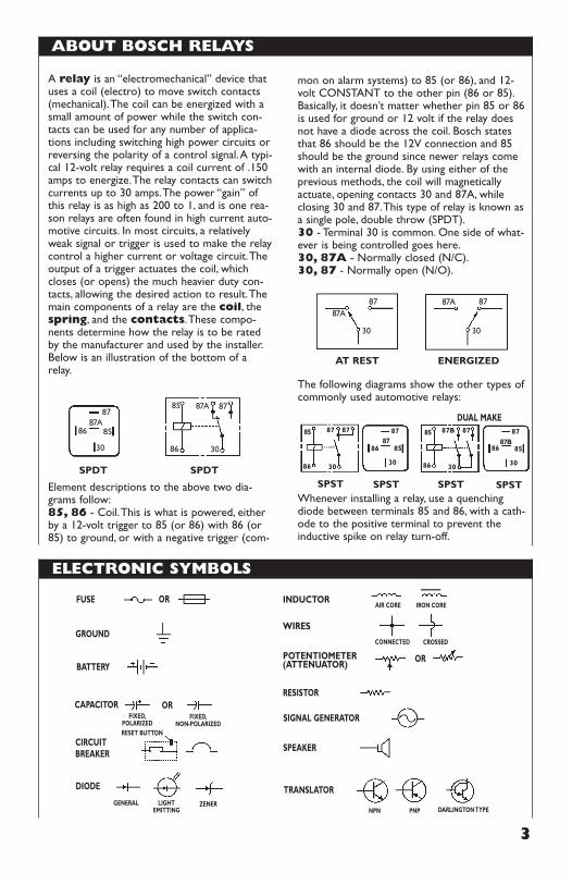
mon on alarm systems) to 85 (or 86), and 12-volt CONSTANT to the other pin (86 or 85).Basically, it doesn’t matter whether pin 85 or 86is used for ground or 12 volt if the relay doesnot have a diode across the coil. Bosch statesthat 86 should be the 12V connection and 85should be the ground since newer relays comewith an internal diode. By using either of theprevious methods, the coil will magneticallyactuate, opening contacts 30 and 87A, whileclosing 30 and 87.This type of relay is known asa single pole, double throw (SPDT).30 - Terminal 30 is common. One side of what-ever is being controlled goes here.30, 87A - Normally closed (N/C).30, 87 - Normally open (N/O).
The following diagrams show the other types ofcommonly used automotive relays:
Whenever installing a relay, use a quenchingdiode between terminals 85 and 86, with a cath-ode to the positive terminal to prevent theinductive spike on relay turn-off.
3
A relay is an “electromechanical” device thatuses a coil (electro) to move switch contacts(mechanical).The coil can be energized with asmall amount of power while the switch con-tacts can be used for any number of applica-tions including switching high power circuits orreversing the polarity of a control signal.A typi-cal 12-volt relay requires a coil current of .150amps to energize.The relay contacts can switchcurrents up to 30 amps.The power “gain” ofthis relay is as high as 200 to 1, and is one rea-son relays are often found in high current auto-motive circuits. In most circuits, a relativelyweak signal or trigger is used to make the relaycontrol a higher current or voltage circuit.Theoutput of a trigger actuates the coil, whichcloses (or opens) the much heavier duty con-tacts, allowing the desired action to result.Themain components of a relay are the coil, thespring, and the contacts.These compo-nents determine how the relay is to be ratedby the manufacturer and used by the installer.Below is an illustration of the bottom of arelay.
Element descriptions to the above two dia-grams follow:85, 86 - Coil.This is what is powered, eitherby a 12-volt trigger to 85 (or 86) with 86 (or85) to ground, or with a negative trigger (com-
ABOUT BOSCH RELAYS
87
86
30
SPDT SPDT
AT REST ENERGIZED
8587A
87
86 30
85 87A
87
30
87A87
30
87A
86 30
85 87
8586
87 87
30
87
SPST SPST
86 30
85 87
8586
87B 87
30
87B
SPST SPST
DUAL MAKE
FUSE OR
GROUND
ORRESISTOR
SIGNAL GENERATOR
SPEAKER
TRANSLATOR
OR
PNPNPN DARLINGTON TYPE
WIRES
POTENTIOMETER(ATTENUATOR)
INDUCTOR
CONNECTED CROSSED
AIR CORE IRON CORE
BATTERY
CAPACITOR
CIRCUITBREAKER
RESET BUTTON
DIODE
FIXED,POLARIZED
FIXED,NON-POLARIZED
GENERAL LIGHTEMITTING
ZENER
ELECTRONIC SYMBOLS
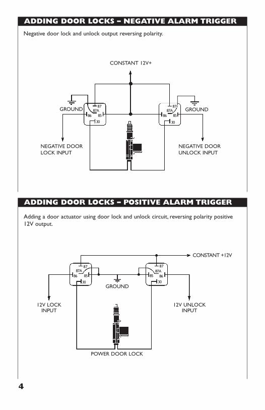
ADDING DOOR LOCKS – NEGATIVE ALARM TRIGGER
ADDING DOOR LOCKS – POSITIVE ALARM TRIGGER
4
POWER DOOR LOCK
12V UNLOCKINPUT
12V LOCKINPUT
GROUND
87
CONSTANT +12V
8687A
30
85
87
8687A
30
85
Adding a door actuator using door lock and unlock circuit, reversing polarity positive12V output.
Negative door lock and unlock output reversing polarity.
CONSTANT 12V+
87
NEGATIVE DOORUNLOCK INPUT
NEGATIVE DOORLOCK INPUT
8687A
30
85
87
8687A
30
85
GROUND GROUND

NEGATIVE-PULSE DOOR LOCKS/NEGATIVE ALARM OUTPUT
POSITIVE-PULSE DOOR LOCKS/NEGATIVE ALARM OUTPUT
5
GROUND
NEGATIVE TRIPFROM SWITCH
FROM ALARMDOOR LOCKDRIVER OUTPUT
TO DOOR LOCKS,POWER (12V POSITIVE)AND GROUND
87
12V POSITIVE8687A
30
85
87
8687A
30
85
FACTORY LOCK RELAY SYSTEM
This wiring diagram is for cars with factory lock relays.
POSITIVE TRIPFROM SWITCH
FROM ALARMDOOR DRIVEROUTPUT
TO DOOR LOCKS,POWER (12V POSITIVE)AND GROUND
87
12V POSITIVE8687A
30
85
87
8687A
30
85
FACTORY LOCK RELAY SYSTEM
This wiring diagram is for cars with factory lock relays.
REVERSE POLARITY DOOR LOCKS/REST AT GROUND
REVERSE POLARITY DOOR LOCKS/REST OPEN CIRCUIT (A)
6
FROM ALARM DOORLOCK DRIVER OUTPUTS TO DOOR LOCK
SWITCH CUT
CUT
87
12V POSITIVE
8687A
30
85
87
8687A
30
85
Wires for factory reversing polarity locks will show constant ground (–) when not inuse.When cutting the factory wires, the wires retaining the constant ground are theswitch (or relay) outputs.
+12VDCMAIN
LOCK PULSEFROM ALARM
LOCK PULSEFROM ALARM
POWERDOORLOCK
SWITCH
TO ACTUATOR
LOCK(TO ACTUATOR)
LOCK(TO SWITCH)
UNLOCK(TOSWITCH)
UNLOCK(TO
ACTUATOR)
LOCK
FUSE
UNLOCK
+12V MAIN
X CUT X
XCUTX
GROUND
87 8687A
30
85 87 8687A
30
8587 8687A
3085
87
8687A30
85
For Toyota Vans 1983 to 1985.
ALARM
INTERFACE W/DUAL VOLTAGE SYSTEMS – 1994 PROBE
7
REVERSE POLARITY DOOR LOCK/REST OPEN CIRCUIT(B)Alarm with (–) outputs.
+12VDC GROUND
GROUND87
8687A
30
85
87
8687A
30
85
87
8687A
30
85
87
8687A
30
85
L
U
Green/Black wire in door lock module is located in the passenger’s kick panel.
4.7 K
TO POWER DOOR LOCKCONTROL WIRE
12V+ HOT
ALARMNEGATIVEUNLOCK
ALARMNEGATIVE
LOCK
87
86 87A
30
85
87
86 87A
30
85
+12VDC
+12VDC +12VDC
DOOR LOCK SYSTEM USING VACUUM PUMP
PASSENGER DOOR UNLOCK BYPASS CIRCUIT
8
ALARM
VACUUMPUMP
TOSWITCH
SIDELOCK
(PULSE FROM ALARM)UNLOCK
(PULSE FROMALARM)
DOOR KEYCYLINDER
ANDSWITCH
UNIT
+12VMAIN
+12VDC
FUSECUT
X
X
GROUND
TRIGGER TO PUMPTO PUMP
SIDE
DOOR LOCKOUTPUT
87
8687A
30
85
87
8687A
30
85
Pump is activated by reversing polarity on single lead from door lock cylinder/switchto vacuum pump.
CAPACITORC1
FROM (–)DOOR
UNLOCKOUTPUTPASSENGER
DOOR LOCKACTUATOR
RELAY #1 RELAY #2
GROUND
FROM (+)SIREN
OUTPUT
TO CONSTANT+12VDC
87
86 87A
30
85
87
8587A
30
86
The value of CAPACITOR C1 controls how long RELAY #2 will remain energized once the sirenchirp(s) stop.This value should be adjusted to make sure RELAY #2 is energized when the doorunlock pulse comes through. Start with 4,700 uF, and increase by 4,700uF for every .50 to .75 sec-onds of delay time desired.
SELECTIVE DOOR UNLOCK/NEGATIVE PULSE SYSTEM
SELECTIVE DOOR UNLOCK/POSITIVE PULSE SYSTEM
9
CUT TAN
GRAY
MM
OEM DOORLOCKRELAYS
LEFTDOORLOCK
SWITCH
RIGHTDOORLOCK
SWITCH
FUSEDCONSTANT
+12VDC
UNLOCKRELAY
LOCKORANGE
LIGHT BLUE
BLACK
ORANGE
UNLOCK
LOCK
UNLOCK
LOCKRELAY
FUSE HOLDERWITH
20 AMP FUSEAT BATTERY
TO UNLOCKOUTPUT OFSECURITYSYSTEM
TO LOCKOUTPUT OFSECURITYSYSTEM
TO AUXILIARYOUTPUT OFSECURITYSYSTEM
CONSTANT+12VDCAT BATTERY
RIGHT DOORLOCK MOTOR
POWER ACCESSORY CIRCUIT BREAKER
LEFT DOORLOCK MOTOR
87
86
30
87A85
87
86
30
87A85
8786
30
87A85
Reprinted with permission from the Installation News 1995 Reference Guide and Fact Book.
FUSE HOLDER WITH 20 AMPFUSE AT BATTERY
CONSTANT+12VDCAT BATTERY87
8687A
30
85
POWER LOCKUNIT
RELAY (BOSCH PART #
0-332-204-150 ORP&B #VF-45F11)
NOTE: HEAVY LINES REPRESENTWIRE THAT IS AT LEAST 16 GAUGE.
M M M M
UNLOCK OUTPUT (POSITIVE)
LOCK OUTPUT (POSITIVE)
LOCK INPUT
UNLOCK INPUT
LOCK INPUT
UNLOCK INPUT
BATTERYFUSE LOCK OUTPUT OF
SECURITY SYSTEMAUXILIARY
OUTPUT OFSECURITYSYSTEM
GROUND
TO UNLOCK OUTPUTOF SECURITY SYSTEM
LEFT DOORLOCK SWITCH
LEFT FRONTLOCK MOTOR
LEFT REARLOCK MOTOR
RIGHT REARLOCK MOTOR
RIGHT FRONTLOCK MOTOR
RIGHT DOORLOCK SWITCH
CUT
LOCK
UNLOCK
LOCK
UNLOCK
Reprinted with permission from the Installation News 1995 Reference Guide and Fact Book.
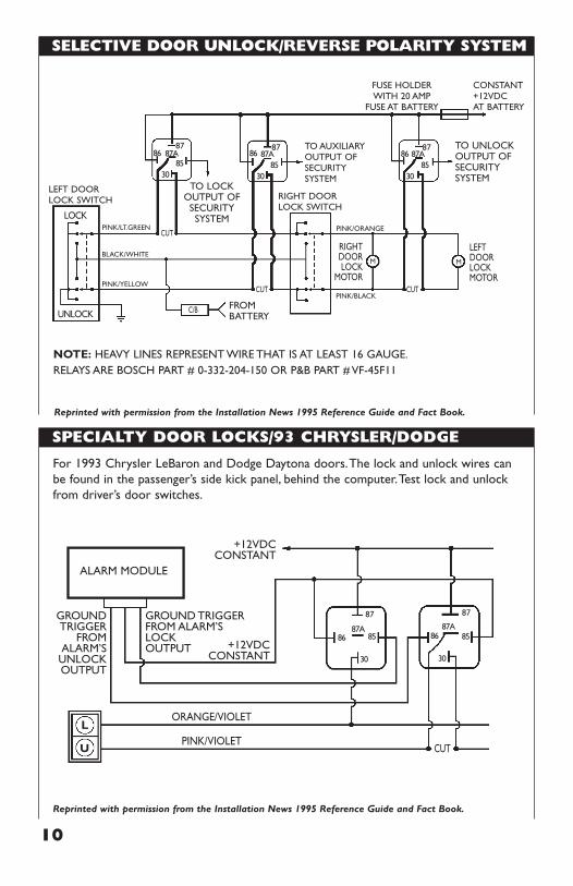
SELECTIVE DOOR UNLOCK/REVERSE POLARITY SYSTEM
SPECIALTY DOOR LOCKS/93 CHRYSLER/DODGE
10
8786 87A
3085
8786 87A
3085
8786 87A
3085
Reprinted with permission from the Installation News 1995 Reference Guide and Fact Book.
CUT
CUT CUT
C/B
PINK/ORANGE
PINK/BLACK
PINK/LT.GREEN
BLACK/WHITE
PINK/YELLOW
MM
UNLOCK
LOCK
TO UNLOCKOUTPUT OFSECURITYSYSTEM
TO LOCKOUTPUT OF
SECURITYSYSTEM
NOTE: HEAVY LINES REPRESENT WIRE THAT IS AT LEAST 16 GAUGE.RELAYS ARE BOSCH PART # 0-332-204-150 OR P&B PART # VF-45F11
FROMBATTERY
CONSTANT+12VDCAT BATTERY
FUSE HOLDERWITH 20 AMP
FUSE AT BATTERY
TO AUXILIARYOUTPUT OFSECURITYSYSTEM
RIGHT DOORLOCK SWITCH
LEFT DOORLOCK SWITCH
RIGHTDOORLOCK
MOTOR
LEFTDOORLOCKMOTOR
+12VDCCONSTANT
+12VDCCONSTANT
GROUNDTRIGGER
FROMALARM’S
UNLOCKOUTPUT
L
U
GROUND TRIGGERFROM ALARM’SLOCKOUTPUT
Reprinted with permission from the Installation News 1995 Reference Guide and Fact Book.
For 1993 Chrysler LeBaron and Dodge Daytona doors.The lock and unlock wires canbe found in the passenger’s side kick panel, behind the computer.Test lock and unlockfrom driver’s door switches.
ORANGE/VIOLET
PINK/VIOLETCUT
ALARM MODULE
87
86
30
87A85
87
86
30
87A85
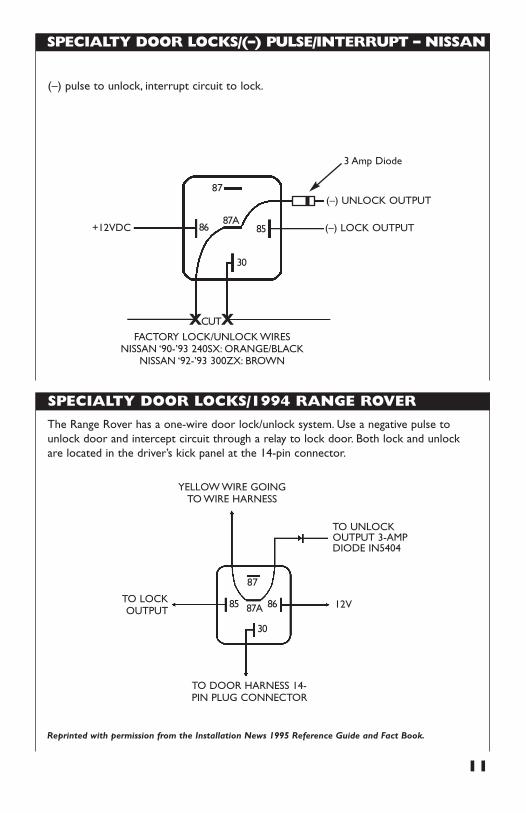
SPECIALTY DOOR LOCKS/(–) PULSE/INTERRUPT – NISSAN
SPECIALTY DOOR LOCKS/1994 RANGE ROVER
11
XCUTX
(–) LOCK OUTPUT
FACTORY LOCK/UNLOCK WIRESNISSAN ‘90-’93 240SX: ORANGE/BLACK
NISSAN ‘92-’93 300ZX: BROWN
(–) UNLOCK OUTPUT
3 Amp Diode
+12VDC
87
8687A
30
85
(–) pulse to unlock, interrupt circuit to lock.
YELLOW WIRE GOINGTO WIRE HARNESS
TO LOCKOUTPUT
TO UNLOCKOUTPUT 3-AMPDIODE IN5404
TO DOOR HARNESS 14-PIN PLUG CONNECTOR
12V
87
8687A
30
85
Reprinted with permission from the Installation News 1995 Reference Guide and Fact Book.
The Range Rover has a one-wire door lock/unlock system. Use a negative pulse tounlock door and intercept circuit through a relay to lock door. Both lock and unlockare located in the driver’s kick panel at the 14-pin connector.
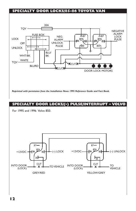
SPECIALTY DOOR LOCKS/85-86 TOYOTA VAN
SPECIALTY DOOR LOCKS/(–) PULSE/INTERRUPT – VOLVO
12
BLU/RD
LOCK
OFF
UNLOCK
20A
FUSE BOXNEG.
ALARMUNLOCK
PULSE
NEGATIVEALARMLOCKPULSE
DOOR LOCK MOTORS
WHT/BKBLU/BK
TQV
TQV
87
8687A
30
85
87
8687A
30
85
Reprinted with permission from the Installation News 1995 Reference Guide and Fact Book.
+12VDC+12VDC (–) LOCK
TO VEHICLE
GREY/RED YELLOW/GREY
TOVEHICLE
(–) UNLOCK
INTO DOOR(LOCK)
INTO DOOR(LOCK) XX
87
8687A
30
85
87
8687A
30
85
For 1995 and 1996 Volvo 850.
WHITE
XCUTXXCUTX
CUT CUT
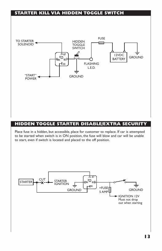
STARTER KILL VIA HIDDEN TOGGLE SWITCH
HIDDEN TOGGLE STARTER DISABLE/EXTRA SECURITY
13
TO STARTERSOLENOID
HIDDENTOGGLESWITCH
“START”POWER
87
GROUND
FLASHINGL.E.D.
FUSE
8687A
30
85
12VDCBATTERY GROUND
Place fuse in a hidden, but accessible, place for customer to replace. If car is attemptedto be started when switch is in ON position, the fuse will blow and car will be unableto start, even if switch is located and placed to the off position.
CUTXSTARTER STARTER
IGNITION
87
GROUNDGROUND
IGNITION 12VMust not dropout when starting
8687A
30
85
+FUSE5 AMP
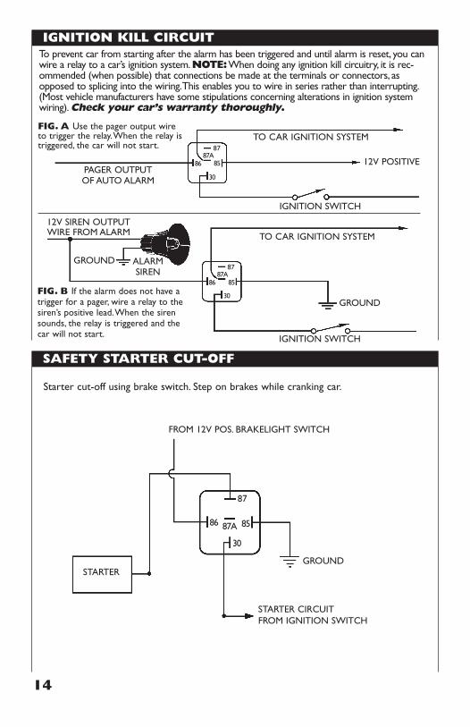
IGNITION KILL CIRCUIT
SAFETY STARTER CUT-OFF
14
To prevent car from starting after the alarm has been triggered and until alarm is reset, you canwire a relay to a car’s ignition system.NOTE:When doing any ignition kill circuitry, it is rec-ommended (when possible) that connections be made at the terminals or connectors, asopposed to splicing into the wiring.This enables you to wire in series rather than interrupting.(Most vehicle manufacturers have some stipulations concerning alterations in ignition systemwiring).Check your car’s warranty thoroughly.
TO CAR IGNITION SYSTEM
TO CAR IGNITION SYSTEM
87
IGNITION SWITCH
IGNITION SWITCH
12V POSITIVE8687A
30
85PAGER OUTPUTOF AUTO ALARM
87GROUND
GROUND
8687A
30
85
ALARMSIREN
FIG. B If the alarm does not have atrigger for a pager, wire a relay to thesiren’s positive lead.When the sirensounds, the relay is triggered and thecar will not start.
FIG. A Use the pager output wireto trigger the relay.When the relay istriggered, the car will not start.
12V SIREN OUTPUTWIRE FROM ALARM
Starter cut-off using brake switch. Step on brakes while cranking car.
STARTER
87
86 87A
30
85
FROM 12V POS. BRAKELIGHT SWITCH
STARTER CIRCUITFROM IGNITION SWITCH
GROUND
STEALTH STARTER INTERRUPT
STARTER DISABLE/CIGARETTE LIGHTER INOPERATIVE
15
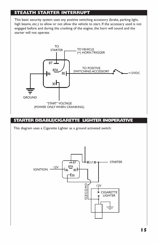
This diagram uses a Cigarette Lighter as a ground activated switch:
IGNITION
GROUND
87
12V
12V
8687A
30
85
CUT
CIGARETTELIGHTER
STARTER
This basic security system uses any positive switching accessory (brake, parking light,high beams, etc.) to allow or not allow the vehicle to start. If the accessary used is notengaged before and during the cranking of the engine, the horn will sound and thestarter will not operate.
TOSTARTER
GROUND
TO VEHICLE(+) HORN TRIGGER
87
8687A
30
85 +12VDC
“START” VOLTAGE(POWER ONLY WHEN CRANKING)
TO POSITIVESWITCHING ACCESSORY
STARTER DISABLE/CIGARETTE LIGHTER OPERATIVE
KEYLESS ENTRY W/CIGARETTE LIGHTER/EXTRA SECURITY
16
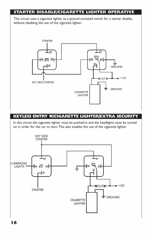
In this circuit the cigarette lighter must be pushed-in and the headlights must be turnedon in order for the car to start.This also enables the use of the cigarette lighter.
(+)PARKINGLIGHTS
STARTER
KEY SIDESTARTER
GROUND
+12VXCUTX
CIGARETTELIGHTER
87
8687A
3085
87
86 87A
30
85
This circuit uses a cigarette lighter as a ground activated switch for a starter disable,without disabling the use of the cigarette lighter.
STARTER
87
86 87A
30
85
87
8687A
30
85
CIGARETTELIGHTER
GROUND
GROUND
+12VX CUT XKEY SIDE STARTER
ALARM TRIGGER INVERTER
ADDING A PAGER TO AN EXISTING ALARM
17
12V OUT TO ALARM TRIGGER
87
12V POSITIVE
12V POSITIVE8687A
3085
DOOR SWITCH
GROUND
GROUND OUT TO ALARM TRIGGER
87
GROUND
GROUND8687A
3085
DOOR SWITCH
FIG. B Switches a 12V dome light trigger switch to a groundsensor output
FIG. A Switches a grounding domelight to a 12V sensor output.
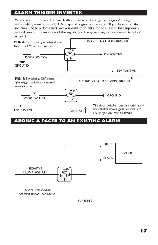
The door switches can be motion sen-sors, shaker boxes, glass sensors...etc.,any trigger you wish to invert.
12V POSITIVE
Most alarms on the market have both a positive and a negative trigger.Although bothare supplied, sometimes only ONE type of trigger can be wired. If you have a car thatswitches 12V to a dome light and you want to install a motion sensor that supplies aground, you must invert one of the signals. (i.e.The grounding motion sensor to a 12Vsensor.)
TO ANTENNA SIDEOF ANTENNA TRIP LEAD
87
8687A
3085
GROUND
RED
PAGER
BLACK
NEGATIVETRUNK SWITCH
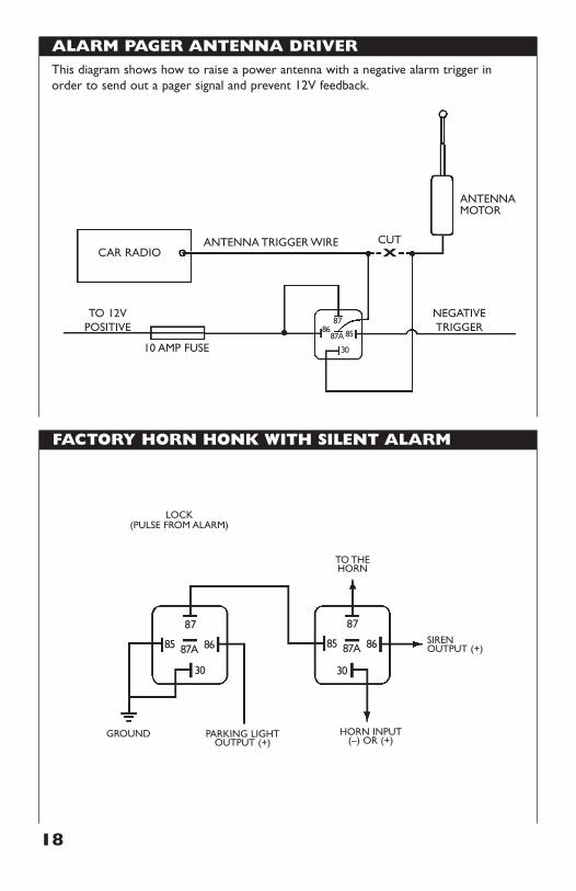
ALARM PAGER ANTENNA DRIVER
FACTORY HORN HONK WITH SILENT ALARM
18
PARKING LIGHTOUTPUT (+)
HORN INPUT(–) OR (+)
SIRENOUTPUT (+)
TO THEHORN
LOCK(PULSE FROM ALARM)
GROUND
87
8687A
30
85
87
8687A
30
85
This diagram shows how to raise a power antenna with a negative alarm trigger inorder to send out a pager signal and prevent 12V feedback.
ANTENNA TRIGGER WIRE
TO 12VPOSITIVE
NEGATIVETRIGGER
87
CUTX
8687A
30
85
10 AMP FUSE
ANTENNAMOTOR
CAR RADIO
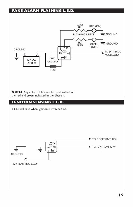
IGNITION SENSING L.E.D.
19
FAKE ALARM FLASHING L.E.D.
NOTE: Any color L.E.D.’s can be used instead ofthe red and green indicated in the diagram.
220ΩR1
R2680Ω
RED (ON)
GREEN(OFF)
FLASHING L.E.D.’S
FUSE
12V DCBATTERY
87
8687A
30
85
GROUND
GROUND
GROUND
TO (+) 12VDCACCESSORY
GROUND
L.E.D. will flash when ignition is switched off.
GROUND
87
12V FLASHING L.E.D.
8687A
30
85
TO CONSTANT 12V+
TO IGNITION 12V+
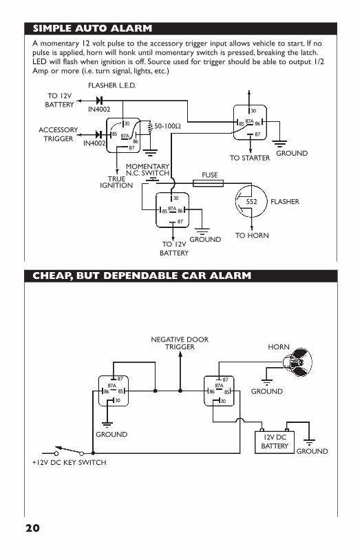
SIMPLE AUTO ALARM
CHEAP, BUT DEPENDABLE CAR ALARM
20
GROUND
GROUND
GROUND
+12V DC KEY SWITCH
HORN
87
12V DCBATTERY
8687A
30
85
87
8687A
30
85
NEGATIVE DOORTRIGGER
A momentary 12 volt pulse to the accessory trigger input allows vehicle to start. If nopulse is applied, horn will honk until momentary switch is pressed, breaking the latch.LED will flash when ignition is off. Source used for trigger should be able to output 1/2Amp or more (i.e. turn signal, lights, etc.)
IN4002
FLASHER L.E.D.
IN4002
50-100Ω
TO 12VBATTERY
FLASHER552
TO HORN
FUSEMOMENTARYN.C. SWITCH
TRUEIGNITION
87GROUND
TO STARTER
8687A
30
85
87
8687A
30
85
87
8687A
30
85
GROUND
TO 12VBATTERY
ACCESSORY TRIGGER
21
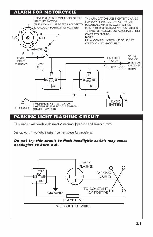
ALARM FOR MOTORCYCLE
PARKING LIGHT FLASHING CIRCUIT
This circuit will work with most American, Japanese and Korean cars.
See diagram “Two-Way Flasher” on next page for headlights.
Do not try this circuit to flash headlights as this may causeheadlights to burn-out.
SIREN OUTPUT WIRE
15 AMP FUSE
GROUNDTO CONSTANT
12V POSITIVE
PARKINGLIGHTS
#552FLASHER
87
8687A
30
85
12VDCINPUT
CURRENT
12VDCBATTERY
87
86 87A
30
+ –
85
LATCHED12VDC
87
1 AMPDIODE 1 AMP DIODE
A BA B
CORD
N/C N/O
C
12
6
86 87A
30
85
THIS APPLICATION USES TIGHT-FIT CHASSISBOX #007 (2 5/16” L; 2 1/8” W; 1 3/4” D).SOLDER ALL WIRES TO CONNECTINGPOINTS (FOR VIBRATION) AND USE SHRINKTUBING TO INSULATE. USE ADJUSTABLE HOSECLAMPS TO SECURE.NOTE:RELAY CONFIGURATION - 87 TO 30 N/O87A TO 30 - N/C (NOT USED)
TO (+)SIDE OFHORN ORANOTHERHORN
UNIVERSAL #9 BUG,VIBRATION OR TILTMERCURY SWITCH.(THE SHOCK MUST BE SET AS CLOSE TO12 O’CLOCK POSITION AS POSSIBLE)
MAKE/BREAK KEY SWITCH ORMAKE/BREAK SPST TOGGLE SWITCH.(ON/OFF SWITCH)GROUND
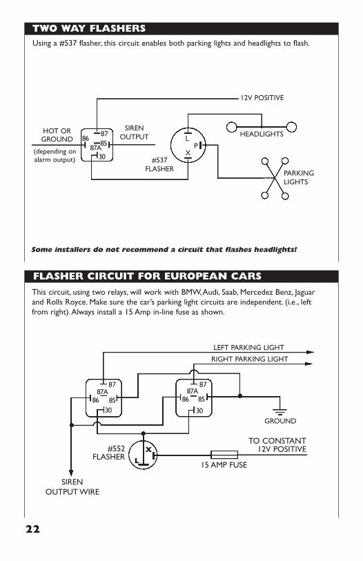
TWO WAY FLASHERS
22
This circuit, using two relays, will work with BMW,Audi, Saab, Mercedez Benz, Jaguarand Rolls Royce. Make sure the car’s parking light circuits are independent. (i.e., leftfrom right).Always install a 15 Amp in-line fuse as shown.
15 AMP FUSE
LEFT PARKING LIGHT
RIGHT PARKING LIGHT
SIRENOUTPUT WIRE
TO CONSTANT12V POSITIVE#552
FLASHER
GROUND
87
8687A
3085
87
8687A
30
X
L
85
FLASHER CIRCUIT FOR EUROPEAN CARS
#537FLASHER PARKING
LIGHTS
SIRENOUTPUT HEADLIGHTS
12V POSITIVE
HOT ORGROUND
(depending onalarm output)
87L
XP
8687A
30
85
Using a #537 flasher, this circuit enables both parking lights and headlights to flash.
Some installers do not recommend a circuit that flashes headlights!
23
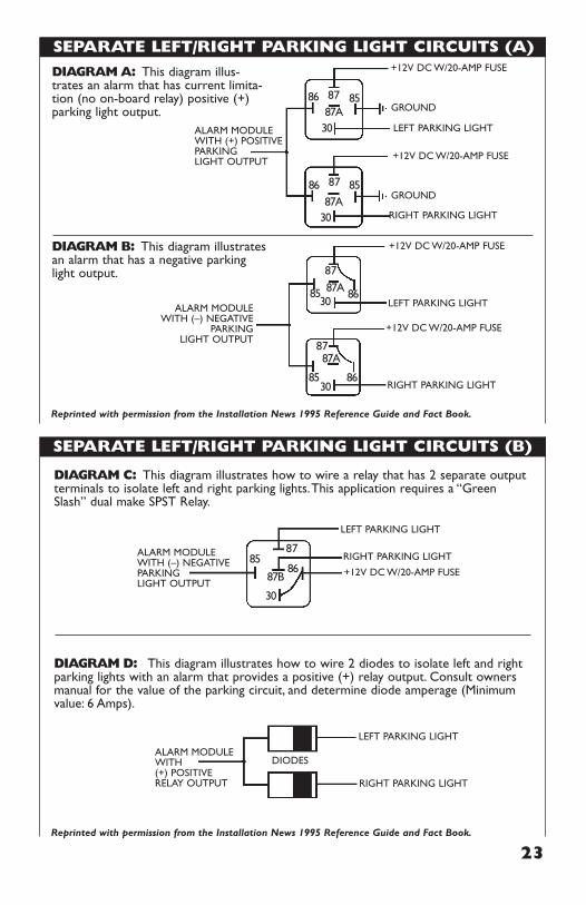
SEPARATE LEFT/RIGHT PARKING LIGHT CIRCUITS (A)
SEPARATE LEFT/RIGHT PARKING LIGHT CIRCUITS (B)
LEFT PARKING LIGHT
RIGHT PARKING LIGHT
+12V DC W/20-AMP FUSE
ALARM MODULEWITH (+) POSITIVE PARKINGLIGHT OUTPUT
+12V DC W/20-AMP FUSE
GROUND
GROUND
87 8587A
30
86
87 8587A
30
86
DIAGRAM A: This diagram illus-trates an alarm that has current limita-tion (no on-board relay) positive (+)parking light output.
LEFT PARKING LIGHT
RIGHT PARKING LIGHT
+12V DC W/20-AMP FUSE
ALARM MODULEWITH (–) NEGATIVE
PARKINGLIGHT OUTPUT
+12V DC W/20-AMP FUSE
87
8687A30
85
87
86
87A
3085
DIAGRAM B: This diagram illustratesan alarm that has a negative parkinglight output.
RIGHT PARKING LIGHT
RIGHT PARKING LIGHT
LEFT PARKING LIGHT
DIODES
+12V DC W/20-AMP FUSE
ALARM MODULEWITH (–) NEGATIVE PARKINGLIGHT OUTPUT
ALARM MODULEWITH (+) POSITIVERELAY OUTPUT
LEFT PARKING LIGHT
8687B
30
8785
DIAGRAM C: This diagram illustrates how to wire a relay that has 2 separate outputterminals to isolate left and right parking lights.This application requires a “GreenSlash” dual make SPST Relay.
DIAGRAM D: This diagram illustrates how to wire 2 diodes to isolate left and rightparking lights with an alarm that provides a positive (+) relay output. Consult ownersmanual for the value of the parking circuit, and determine diode amperage (Minimumvalue: 6 Amps).
Reprinted with permission from the Installation News 1995 Reference Guide and Fact Book.
Reprinted with permission from the Installation News 1995 Reference Guide and Fact Book.
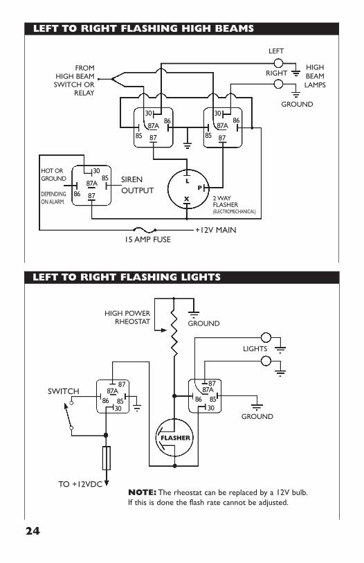
LEFT TO RIGHT FLASHING HIGH BEAMS
LEFT TO RIGHT FLASHING LIGHTS
24
SIRENOUTPUT
HOT ORGROUND
DEPENDINGON ALARM.
RIGHT
GROUND
HIGHBEAMLAMPS
15 AMP FUSE+12V MAIN
2 WAYFLASHER(ELECTROMECHANICAL)
LP
X
LEFT
FROMHIGH BEAMSWITCH OR
RELAY
87
8687A
30
85
878687A
3085
87
8687A
30
85
NOTE: The rheostat can be replaced by a 12V bulb.If this is done the flash rate cannot be adjusted.
SWITCH
LIGHTS
TO +12VDC
FLASHER
GROUND
GROUNDHIGH POWER
RHEOSTAT
87
8687A
3085
87
8687A
3085
25
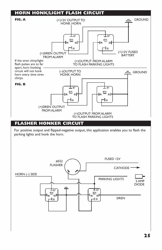
HORN HONK/LIGHT FLASH CIRCUIT
FLASHER HONKER CIRCUIT
For positive output and flipped-negative output, this application enables you to flash theparking lights and honk the horn.
FUSED 12V
CATHODE
5 AMPDIODE
87
PARKING LIGHTS
8687A
30
85
87
8687A
3085
HORN (–) SIDE
#552FLASHER
SIREN
87
(+)12V FUSEDBATTERY
(+)12V OUTPUT TOHONK HORN
(–)OUTPUT TOHONK HORN
(+)OUTPUT FROM ALARMTO FLASH PARKING LIGHTS
(+)OUTPUT FROM ALARMTO FLASH PARKING LIGHTS
8687A
30
85
87
8687A
30
85
(+)SIREN OUTPUTFROM ALARM
If the siren chirp/lightflash pulses are to farapart, horn honkingcircuit will not honkhorn every time sirenchirps.
(+)SIREN OUTPUTFROM ALARM
GROUND
87
GROUND
8687A
30
85
87
8687A
30
85
FIG. B
FIG. A
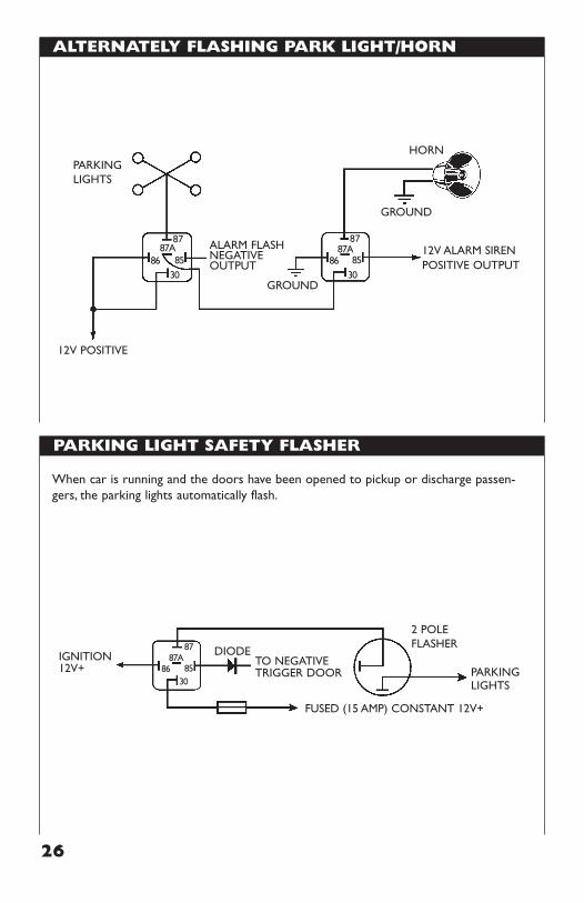
ALTERNATELY FLASHING PARK LIGHT/HORN
PARKING LIGHT SAFETY FLASHER
26
When car is running and the doors have been opened to pickup or discharge passen-gers, the parking lights automatically flash.
DIODETO NEGATIVETRIGGER DOOR
IGNITION12V+
87
FUSED (15 AMP) CONSTANT 12V+
8687A
3085
2 POLEFLASHER
PARKINGLIGHTS
ALARM FLASHNEGATIVEOUTPUT
12V ALARM SIRENPOSITIVE OUTPUT
87
8687A
3085
87
8687A
3085
GROUND
HORN
12V POSITIVE
GROUND
PARKINGLIGHTS
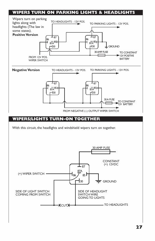
WIPERS TURN ON PARKING LIGHTS & HEADLIGHTS
WIPERS/LIGHTS TURN-ON TOGETHER
27
8786
87A30
85
8786
87A30
30 AMP FUSE
GROUND
TO CONSTANT12V POSITIVEBATTERY
85
Wipers turn on parkinglights along withheadlights (The law insome states).Positive Version
Negative Version
TO HEADLIGHTS - 12V POS.TO PARKING LIGHTS - 12V POS.
FROM 12V POS.WIPER SWITCH
8786
87A30
85
8786
87A30
30 A FUSETO CONSTANT 12V BATTERY
85
TO HEADLIGHTS - 12V POS. TO PARKING LIGHTS - 12V POS.
FROM NEGATIVE (–) OUTPUT WIPER SWITCH
With this circuit, the headlights and windshield wipers turn on together.
CONSTANT(+) 12VDC
(+) WIPER SWITCH
GROUND
87
8687A
30
85
30 AMP FUSE
TO HEADLIGHTSCUT
SIDE OF HEADLIGHTSWITCH WIREGOING TO LIGHTS
SIDE OF LIGHT SWITCHCOMING FROM SWITCH
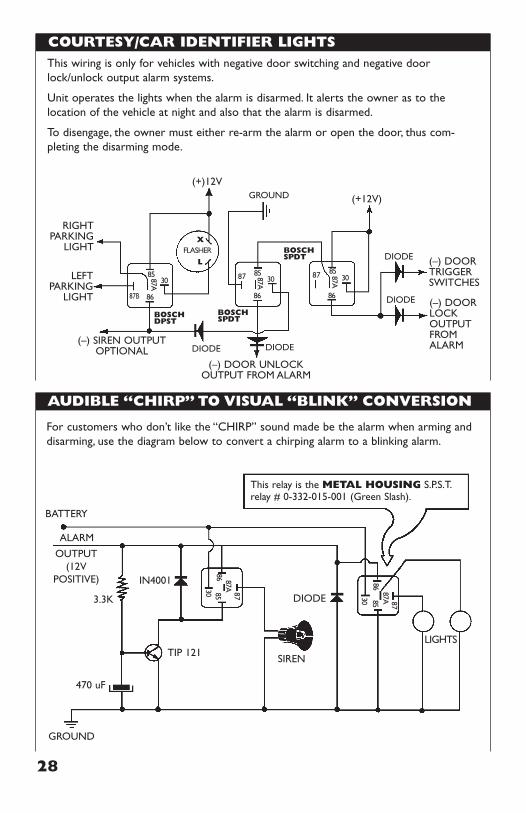
COURTESY/CAR IDENTIFIER LIGHTS
AUDIBLE “CHIRP” TO VISUAL “BLINK” CONVERSION
28
GROUND
DIODE
BOSCHDPST
BOSCHSPDT
BOSCHSPDT DIODE
DIODE
DIODE
(+)12V
(+12V)
RIGHTPARKING
LIGHT
LEFTPARKING
LIGHT
(–) SIREN OUTPUTOPTIONAL
(–) DOOR UNLOCKOUTPUT FROM ALARM
(–) DOORLOCKOUTPUTFROMALARM
87
86
87A 3085 87
86
87A 3085
87B 86
87A 30
X
LFLASHER
85
(–) DOORTRIGGERSWITCHES
This wiring is only for vehicles with negative door switching and negative doorlock/unlock output alarm systems.
Unit operates the lights when the alarm is disarmed. It alerts the owner as to thelocation of the vehicle at night and also that the alarm is disarmed.
To disengage, the owner must either re-arm the alarm or open the door, thus com-pleting the disarming mode.
IN4001
DIODE
SIREN
3.3K
470 uF
TIP 121
87
LIGHTS
86 87A30 85
87
8687A30 85
GROUND
This relay is the METAL HOUSING S.P.S.T.relay # 0-332-015-001 (Green Slash).
BATTERY
ALARM
OUTPUT(12V
POSITIVE)
For customers who don’t like the “CHIRP” sound made be the alarm when arming anddisarming, use the diagram below to convert a chirping alarm to a blinking alarm.
29
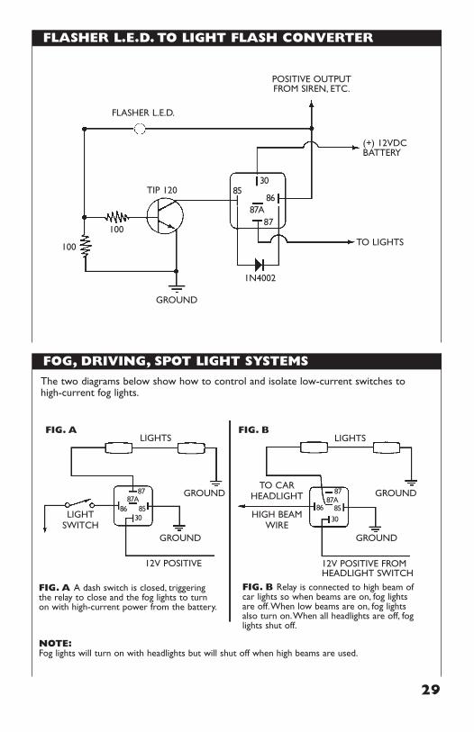
FLASHER L.E.D. TO LIGHT FLASH CONVERTER
FOG, DRIVING, SPOT LIGHT SYSTEMS
The two diagrams below show how to control and isolate low-current switches tohigh-current fog lights.
FIG. B Relay is connected to high beam ofcar lights so when beams are on, fog lightsare off.When low beams are on, fog lightsalso turn on.When all headlights are off, foglights shut off.
12V POSITIVE 12V POSITIVE FROMHEADLIGHT SWITCH
FIG. A A dash switch is closed, triggeringthe relay to close and the fog lights to turnon with high-current power from the battery.
NOTE:Fog lights will turn on with headlights but will shut off when high beams are used.
TO CARHEADLIGHT
HIGH BEAMWIRE
LIGHTSWITCH
GROUND
GROUND
GROUND
GROUND
LIGHTSFIG. A FIG. B
LIGHTS
87
8687A
3085
87
8687A
3085
TIP 120
100
100
87
8687A
3085
GROUND
1N4002
TO LIGHTS
(+) 12VDCBATTERY
POSITIVE OUTPUTFROM SIREN, ETC.
FLASHER L.E.D.
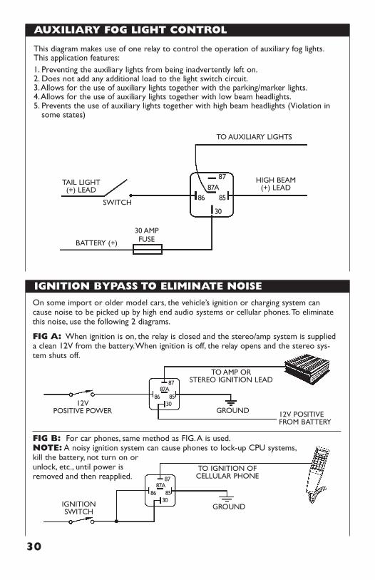
AUXILIARY FOG LIGHT CONTROL
IGNITION BYPASS TO ELIMINATE NOISE
30
This diagram makes use of one relay to control the operation of auxiliary fog lights.This application features:1. Preventing the auxiliary lights from being inadvertently left on.2. Does not add any additional load to the light switch circuit.3.Allows for the use of auxiliary lights together with the parking/marker lights.4.Allows for the use of auxiliary lights together with low beam headlights.5. Prevents the use of auxiliary lights together with high beam headlights (Violation in
some states)
TO AUXILIARY LIGHTS
BATTERY (+)
HIGH BEAM(+) LEAD
87
8687A
30
85
30 AMPFUSE
SWITCH
TAIL LIGHT(+) LEAD
On some import or older model cars, the vehicle’s ignition or charging system cancause noise to be picked up by high end audio systems or cellular phones.To eliminatethis noise, use the following 2 diagrams.
FIG A: When ignition is on, the relay is closed and the stereo/amp system is supplieda clean 12V from the battery.When ignition is off, the relay opens and the stereo sys-tem shuts off.
FIG B: For car phones, same method as FIG.A is used.NOTE: A noisy ignition system can cause phones to lock-up CPU systems,kill the battery, not turn on or unlock, etc., until power isremoved and then reapplied.
12VPOSITIVE POWER 12V POSITIVE
FROM BATTERY
TO AMP ORSTEREO IGNITION LEAD87
GROUND
8687A
3085
IGNITIONSWITCH
TO IGNITION OFCELLULAR PHONE87
GROUND
8687A
3085
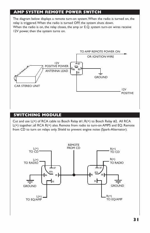
AMP SYSTEM REMOTE POWER SWITCH
SWITCHING MODULE
31
The diagram below displays a remote turn-on system.When the radio is turned on, therelay is triggered.When the radio is turned OFF, the system shuts down.When the radio is on, the relay closes, the amp or E.Q. system turn-on wires receive12V power, then the system turns on.
12VPOSITIVE POWER
ANTENNA LEAD
TO AMP REMOTE POWER ON
OR IGNITION WIRE
CAR STEREO UNIT
87
GROUND
8687A
3085
12VPOSITIVE
L(+)TO EQ/AMP
R(+)TO EQ/AMP
L(+)TO CD
R(+)TO CD
L(+)TO RADIO
GROUND
REMOTEFROM CD
GROUND
87
R(+)TO RADIO
86
87A
30
85
87
8687A
30
85
Cut and use L(+) of RCA cable to Bosch Relay #1; R(+) to Bosch Relay #2. All RCAL(+) together; all RCA R(+) also. Remote from radio to turn-on AMPS and EQ. Remotefrom CD to turn on relays only. Shield to prevent engine noise (Spark-Alternator).
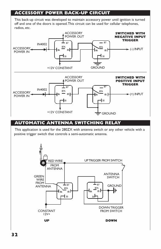
ACCESSORY POWER BACK-UP CIRCUIT
AUTOMATIC ANTENNA SWITCHING RELAY
32
SWITCHED WITHNEGATIVE INPUT
TRIGGERIN4002
ACCESSORYPOWER IN
GROUND+12V CONSTANT
ACCESSORYPOWER OUT
87
(–) INPUT8687A
30
85
87
8687A
30
85
SWITCHED WITHPOSITIVE INPUT
TRIGGER
IN4002ACCESSORYPOWER IN
GROUND+12V CONSTANT
ACCESSORYPOWER OUT
87
(+) INPUT8687A
30
85
87
8687A
30
85
This back-up circuit was developed to maintain accessory power until ignition is turnedoff and one of the doors is opened.This circuit can be used for cellular telephones,radios, etc.
CONSTANT12V+
UP DOWN
DOWN TRIGGERFROM SWITCH
FROMANTENNA
ANTENNASWITCHGREEN
WIREFROMANTENNA
RED WIRE
GROUND87
UP TRIGGER FROM SWITCH
86
87A
30
85
87
8587A
30
86
This application is used for the 280ZX with antenna switch or any other vehicle with apositive trigger switch that controls a semi-automatic antenna.
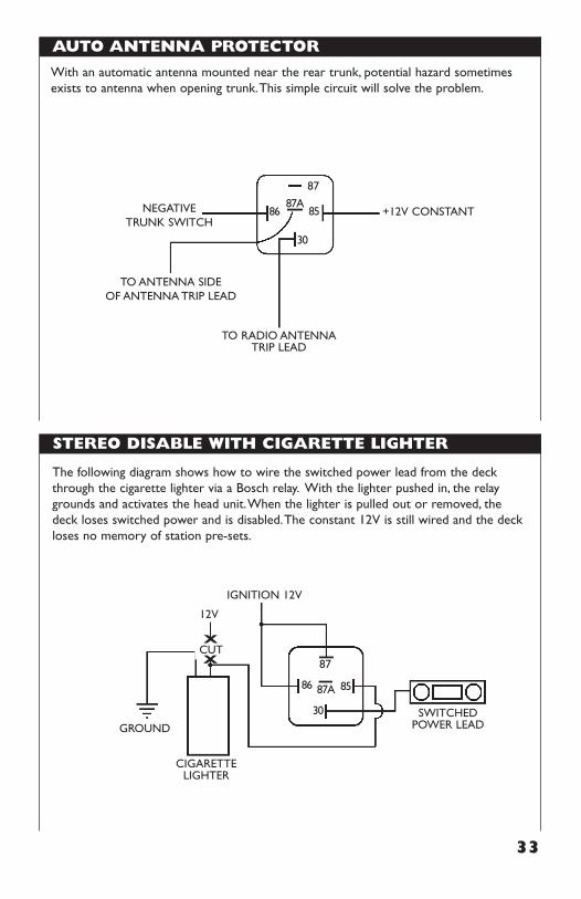
AUTO ANTENNA PROTECTOR
STEREO DISABLE WITH CIGARETTE LIGHTER
33
With an automatic antenna mounted near the rear trunk, potential hazard sometimesexists to antenna when opening trunk.This simple circuit will solve the problem.
TO ANTENNA SIDEOF ANTENNA TRIP LEAD
87
8687A
30
85
TO RADIO ANTENNATRIP LEAD
+12V CONSTANTNEGATIVETRUNK SWITCH
The following diagram shows how to wire the switched power lead from the deckthrough the cigarette lighter via a Bosch relay. With the lighter pushed in, the relaygrounds and activates the head unit.When the lighter is pulled out or removed, thedeck loses switched power and is disabled.The constant 12V is still wired and the deckloses no memory of station pre-sets.
12V
GROUND
87CUTX
X
86 87A
30
85
CIGARETTELIGHTER
SWITCHED POWER LEAD
IGNITION 12V
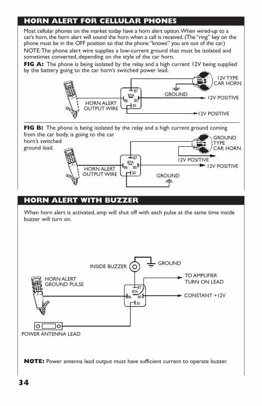
HORN ALERT FOR CELLULAR PHONES
HORN ALERT WITH BUZZER
34
Most cellular phones on the market today have a horn alert option.When wired-up to acar’s horn, the horn alert will sound the horn when a call is received. (The “ring” key on thephone must be in the OFF position so that the phone “knows” you are out of the car.)NOTE:The phone alert wire supplies a low-current ground that must be isolated andsometimes converted, depending on the style of the car horn.FIG A: The phone is being isolated by the relay and a high current 12V being suppliedby the battery going to the car horn’s switched power lead.
FIG B: The phone is being isolated by the relay and a high current ground comingfrom the car body, is going to the car horn’s switchedground lead.
HORN ALERTOUTPUT WIRE
12V POSITIVE
12V POSITIVE
12V TYPECAR HORN
87GROUND
8687A
3085
HORN ALERTOUTPUT WIRE
GROUNDTYPECAR HORN
87
GROUND
12V POSITIVE12V POSITIVE
8687A
3085
When horn alert is activated, amp will shut off with each pulse at the same time insidebuzzer will turn on.
NOTE: Power antenna lead output must have sufficient current to operate buzzer.
HORN ALERTGROUND PULSE
POWER ANTENNA LEAD
INSIDE BUZZER
87
TO AMPLIFIERTURN ON LEAD
GROUND
CONSTANT +12V8687A
30
85
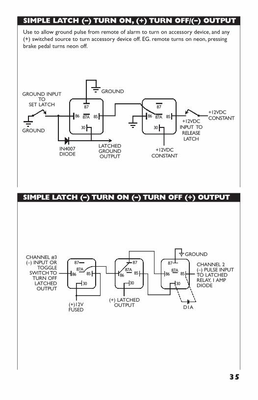
SIMPLE LATCH (–) TURN ON, (+) TURN OFF/(–) OUTPUT
SIMPLE LATCH (–) TURN ON (–) TURN OFF (+) OUTPUT
35
LATCHEDGROUNDOUTPUT
GROUND INPUTTO
SET LATCH
GROUND
IN4007DIODE
GROUND
+12VDCCONSTANT
+12VDCCONSTANT
+12VDC INPUT TORELEASELATCH
87
86 87A
30
85
87
86 87A
30
85
Use to allow ground pulse from remote of alarm to turn on accessory device, and any(+) switched source to turn accessory device off. EG. remote turns on neon, pressingbrake pedal turns neon off.
GROUNDCHANNEL #3(–) INPUT OR
TOGGLESWITCH TO
TURN OFFLATCHEDOUTPUT
(+) LATCHEDOUTPUT(+)12V
FUSED
CHANNEL 2(–) PULSE INPUTTO LATCHEDRELAY, 1 AMPDIODE
D1A
87
8687A
30
85
87
8687A
30
85
87
8687A
30
85
OPTIONAL METHODS OF LATCHING RELAYS (1)
36
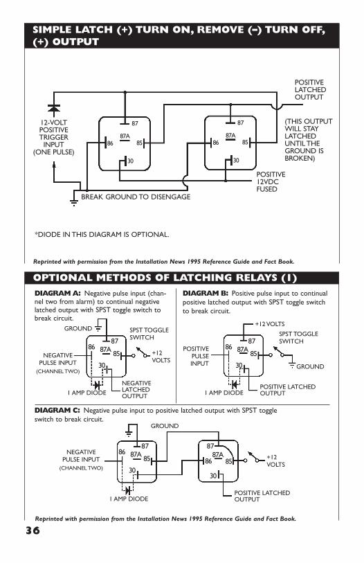
SIMPLE LATCH (+) TURN ON, REMOVE (–) TURN OFF,(+) OUTPUT
Reprinted with permission from the Installation News 1995 Reference Guide and Fact Book.
12-VOLTPOSITIVETRIGGER
INPUT(ONE PULSE)
BREAK GROUND TO DISENGAGE
*DIODE IN THIS DIAGRAM IS OPTIONAL.
POSITIVE12VDCFUSED
(THIS OUTPUTWILL STAYLATCHEDUNTIL THEGROUND ISBROKEN)
POSITIVELATCHEDOUTPUT
87
8687A
30
85
87
8687A
30
85
+12VOLTS
SPST TOGGLESWITCH
DIAGRAM A: Negative pulse input (chan-nel two from alarm) to continual negativelatched output with SPST toggle switch tobreak circuit.
DIAGRAM C: Negative pulse input to positive latched output with SPST toggle switch to break circuit.
DIAGRAM B: Positive pulse input to continualpositive latched output with SPST toggle switchto break circuit.
GROUND
GROUND
GROUND
1 AMP DIODE
1 AMP DIODE
NEGATIVELATCHEDOUTPUT
NEGATIVEPULSE INPUT
(CHANNEL TWO)
NEGATIVEPULSE INPUT
(CHANNEL TWO)
8786 87A
30
85
+12 VOLTS
SPST TOGGLESWITCH
1 AMP DIODEPOSITIVE LATCHEDOUTPUT
+12VOLTS
POSITIVE LATCHEDOUTPUT
POSITIVEPULSEINPUT
8786 87A
30
85
8786 87A
30
85
87
8687A
30
85
Reprinted with permission from the Installation News 1995 Reference Guide and Fact Book.
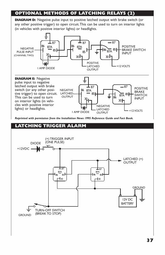
OPTIONAL METHODS OF LATCHING RELAYS (2)
LATCHING TRIGGER ALARM
37
POSITIVEBRAKE SWITCHINPUT
8786 87A
3085
8786 87A
30
85
87
86 87A
30
85
+12 VOLTSPOSITIVELATCHEDOUTPUT
DIAGRAM D: Negative pulse input to positive latched output with brake switch (orany other positive trigger) to open circuit.This can be used to turn on interior lights(in vehicles with positive interior lights) or headlights.
DIAGRAM E: Negativepulse input to negativelatched output with brakeswitch (or any other posi-tive trigger) to open circuit.This can be used to turnon interior lights (in vehi-cles with positive interiorlights) or headlights.
1 AMP DIODE
NEGATIVEPULSE INPUT
(CHANNEL TWO)
POSITIVEBRAKE SWITCHINPUT
8786 87A
30
85
87
8687A
30
85
+12 VOLTS
NEGATIVELATCHEDOUTPUT
1 AMP DIODE
NEGATIVELATCHED OUTPUT
GROUND
GROUND
DIODE
+12VDC
TURN-OFF SWITCH(BREAK TO STOP)
LATCHED (+)OUTPUT
87
12V DCBATTERY
8687A
30
85
87
8687A
30
85
(+) TRIGGER INPUT(ONE PULSE)
Reprinted with permission from the Installation News 1995 Reference Guide and Fact Book.
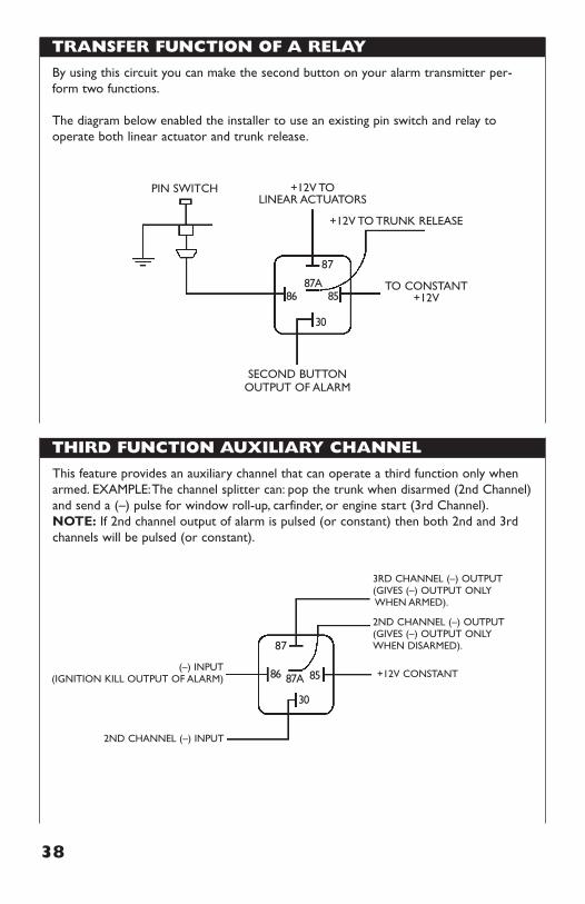
TRANSFER FUNCTION OF A RELAY
38
THIRD FUNCTION AUXILIARY CHANNEL
By using this circuit you can make the second button on your alarm transmitter per-form two functions.
The diagram below enabled the installer to use an existing pin switch and relay tooperate both linear actuator and trunk release.
+12V TOLINEAR ACTUATORS
PIN SWITCH
87
8687A
30
85
+12V TO TRUNK RELEASE
SECOND BUTTONOUTPUT OF ALARM
TO CONSTANT+12V
This feature provides an auxiliary channel that can operate a third function only whenarmed. EXAMPLE:The channel splitter can: pop the trunk when disarmed (2nd Channel)and send a (–) pulse for window roll-up, carfinder, or engine start (3rd Channel).NOTE: If 2nd channel output of alarm is pulsed (or constant) then both 2nd and 3rdchannels will be pulsed (or constant).
(–) INPUT(IGNITION KILL OUTPUT OF ALARM)
2ND CHANNEL (–) INPUT
87
86 87A
30
85
3RD CHANNEL (–) OUTPUT(GIVES (–) OUTPUT ONLYWHEN ARMED).
2ND CHANNEL (–) OUTPUT(GIVES (–) OUTPUT ONLYWHEN DISARMED).
+12V CONSTANT
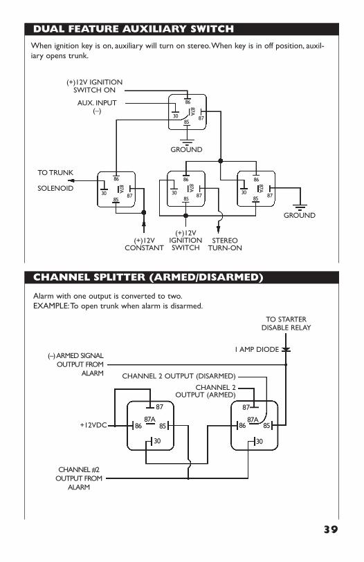
DUAL FEATURE AUXILIARY SWITCH
CHANNEL SPLITTER (ARMED/DISARMED)
39
(+)12VCONSTANT
(+)12VIGNITIONSWITCH
STEREOTURN-ON
(+)12V IGNITIONSWITCH ON
AUX. INPUT(–)
TO TRUNK
SOLENOID
GROUND
GROUND
87
86
87A
3085
87
86
87A
3085
87
86 87A
3085
87
8687A
3085
When ignition key is on, auxiliary will turn on stereo.When key is in off position, auxil-iary opens trunk.
CHANNEL #2OUTPUT FROM
ALARM
(–) ARMED SIGNAL OUTPUT FROM
ALARM
1 AMP DIODE
CHANNEL 2 OUTPUT (DISARMED)
CHANNEL 2 OUTPUT (ARMED)
TO STARTERDISABLE RELAY
+12VDC
87
8687A
30
85
87
8687A
30
85
Alarm with one output is converted to two.EXAMPLE:To open trunk when alarm is disarmed.
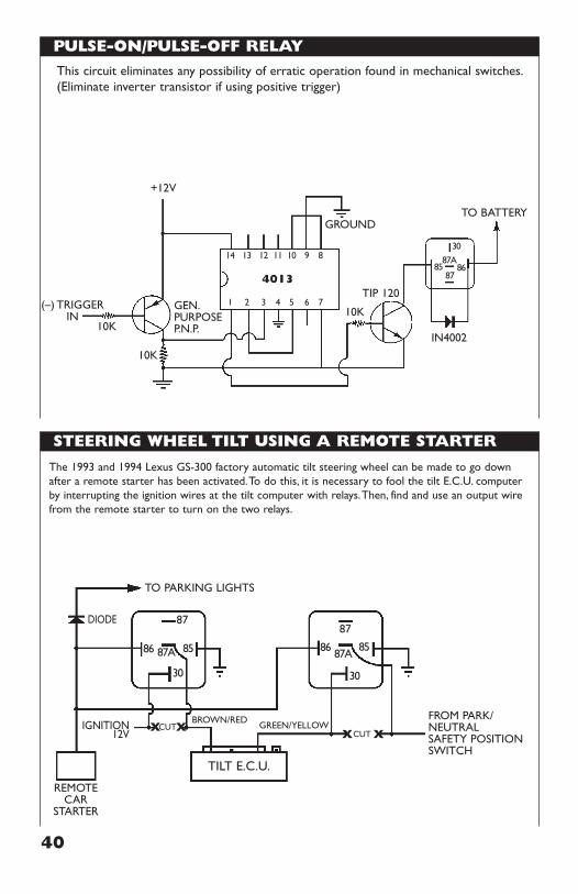
PULSE-ON/PULSE-OFF RELAY
STEERING WHEEL TILT USING A REMOTE STARTER
40
This circuit eliminates any possibility of erratic operation found in mechanical switches.(Eliminate inverter transistor if using positive trigger)
+12V
4013
IN4002
TO BATTERY
(–) TRIGGERIN
87
14 13 12 11 10 9 8
1 2 3 4 5 6 7
8687A
30
85
GEN.PURPOSEP.N.P.
TIP 120
GROUND
10K
10K
10K
GREEN/YELLOWBROWN/RED
TO PARKING LIGHTS
REMOTECAR
STARTER
IGNITION12V
DIODE
FROM PARK/NEUTRALSAFETY POSITIONSWITCH
X X
TILT E.C.U.
CUTX XCUT
87
86 87A
30
85
87
86 87A
30
85
The 1993 and 1994 Lexus GS-300 factory automatic tilt steering wheel can be made to go downafter a remote starter has been activated.To do this, it is necessary to fool the tilt E.C.U. computerby interrupting the ignition wires at the tilt computer with relays.Then, find and use an output wirefrom the remote starter to turn on the two relays.
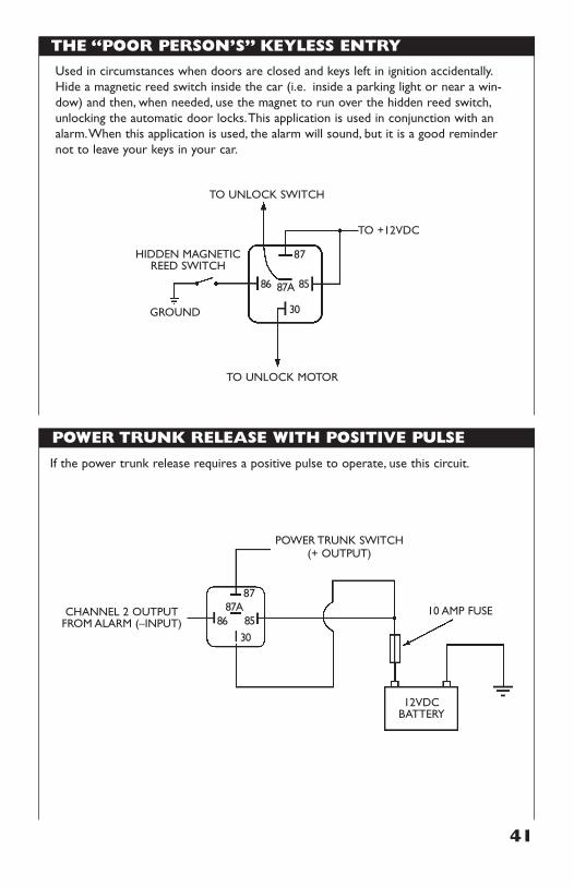
THE “POOR PERSON’S” KEYLESS ENTRY
POWER TRUNK RELEASE WITH POSITIVE PULSE
41
Used in circumstances when doors are closed and keys left in ignition accidentally.Hide a magnetic reed switch inside the car (i.e. inside a parking light or near a win-dow) and then, when needed, use the magnet to run over the hidden reed switch,unlocking the automatic door locks.This application is used in conjunction with analarm.When this application is used, the alarm will sound, but it is a good remindernot to leave your keys in your car.
HIDDEN MAGNETICREED SWITCH
TO +12VDC
87
86 87A
30
85
TO UNLOCK SWITCH
TO UNLOCK MOTOR
GROUND
If the power trunk release requires a positive pulse to operate, use this circuit.
CHANNEL 2 OUTPUTFROM ALARM (–INPUT)
87
POWER TRUNK SWITCH(+ OUTPUT)
8687A
3085
12VDCBATTERY
10 AMP FUSE
42
Endorsed by the Mobile Electronics Association, the M.E.C.P. study guide is the mostcomprehensive book of it’s type available. Designed to prepare installers of different lev-els of expertise, the Study Guide covers electronic theory, car audio, security and cellu-lar installations necessary for the First Class, Specialist and Master Installer Certification.Some of the features found in the guide are:
• Key Formulas • Sample Test Questions• Margin Notes • Glossary• Illustrations
A great reference manual to have around.
Become a Certified Installer. Order Your Copy Today!
MECPMOBILEELECTRONICSCERTIFICATIONPROGRAM
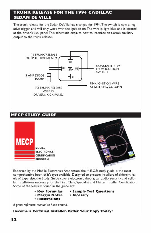
3-AMP DIODEIN5404
(–) TRUNK RELEASEOUTPUT FROM ALARM
TO TRUNK RELEASEWIRE IN
DRIVER’S KICK PANEL
CONSTANT +12VFROM IGNITIONSWITCH
PINK IGNITION WIREAT STEERING COLUMN
87
8687A
30
85
TRUNK RELEASE FOR THE 1994 CADILLAC SEDAN DE VILLE
The trunk release for the Sedan DeVille has changed for 1994.The switch is now a neg-ative trigger and will only work with the ignition on.The wire is light blue and is locatedat the driver’s kick panel.This schematic explains how to interface an alarm’s auxiliaryoutput to the trunk release.
MECP STUDY GUIDE

FREEPRODUCT CATALOG!
Business Type ( Check as many as apply) Distributor Number of installers at your location? Retailer Sales Service Installation Other
Product Type (Check as many as apply) Autosound Auto Security Would you like to receive our monthly fax Cellular specials? We offer monthly fax specials to those Two-Way customers with a dedicated fax line. Other Yes No
No. of Locations 1 2-5 6+
43
YOUR FIRST SOURCE
P A R T S A N D
F O R E L E C T R O N I C
DLC is your First Source for Electronic Partsand Accessories with thousands of items to
chose from in thirteen different categories. Our136 page catalog is available absolutely free by
filling out this form completely, and faxing ormailing it to the address shown below.
Last Name First
Title
Phone ( ) Fax ( )
Company
Business Address
City State Zip
Mail your complete form to: David Levy Company • 12753 Moore St.Cerritos, CA 90703 or Fax it to (800) 421-3538 Attention: Relay Guide