bored cast-in-place reinforced concrete piles … · statement on pile installation tolerances...
TRANSCRIPT
Edition 5 / Revision 1 ROADS AND MARITIME SERVICES January 2019
ROADS AND MARITIME SERVICES (RMS)
QA SPECIFICATION B59
BORED CAST-IN-PLACE REINFORCED CONCRETE PILES (WITHOUT PERMANENT CASING)
NOTICE
This document is a Roads and Maritime Services QA Specification. It has been developed for use with roadworks and bridgeworks contracts let by Roads and Maritime Services or by local councils in NSW. It is not suitable for any other purpose and must not be used for any other purpose or in any other context.
Copyright in this document belongs to Roads and Maritime Services.
REVISION REGISTER
Ed/Rev Number
Clause Number Description of Revision Authorised
By Date
Ed 1/Rev 0 First issued. GM, CMS 24.04.91
Ed 1/Rev 1 B59.10 Pay items and other minor changes. GM, CMS 10.09.91
Ed 1/Rev 2 B59.10(D) Reinforcement is no longer Provisional Quantity. References to RTA B80 deleted
GM, PSP J Woodward
28.08.96
Ed 2/Rev 0 Extensive changes throughout, to align with AS 2159-1995.
GM, RNIC 09.11.98
Ed 2/ Rev 1 Annexure B59/1
New schedule listing Identified Records. GM, RNIC 28.02.00
Ed 2/Rev 2 3.3, 4.1, 8(a) Annex B59/2
Requirements for examination of pile hole changed. New annexure.
GM, RNIC 18.05.00
Ed 2/Rev 3 6.6 Reference to Conditions of Contract changed to suit C1.
GM, RNIC 30.05.01
Ed 3/Rev 0 Various Text revised to direct imperative style.
“Comply” changed to “conform”. ”Contractor” replaced by “you”. ”Superintendent” replaced by “Principal”. “Shall” replaced by “must”.
Minor editorial and font changes.
GM, RNIC 30.08.05
Foreword New clause after the Table of Contents.
1.2 References revised and transferred to new Annex B59/M. Specification structure described.
2.1 From previous Clause 3.4.
2.2 From previous Clauses 5 and 6.1.
1.1, Annex M
AS 2159 replaced by AS 5100

ii
Ed/Rev Number
Clause Number Description of Revision Authorised
By Date
Ed 3/Rev 0 (cont’d)
Clause: renumbered:
1.3, 2, 3, 4, 5, 6, 7, 8, 59/2, 59/1 B59/D, 4, 5, 6, 7, 8, 9, 58/B, 59/A, 59/C
Ed 4/Rev 0 New edition, incorporating learnings from RTA Piling Inspection Workshop and feedback from industry.
GM, IC 17.10.08
Ed 4/Rev 1 5 Coring requirement clarified. GM, IC 24.08.09
Pay Items (a)(i) and (a)(ii)
Pay Items description and scope changed to differentiate between drilling in overburden and coring in rock.
Ed 4/Rev 2 1.2.5 Retitled. Definitions of “you” and “your” added.
GM, IC Bernie Chellingworth
15.01.10
3 6.1
Added: NPER registration as equivalent to CPEng, Engrs Aust, for certification purposes
Annex M Referenced documents updated
Ed 5/Rev 0 Global Clauses rearranged and reworded to improve clarity.
GM, CPS (Peter Letts)
20.02.14
1.1 Statement on pile installation tolerances moved to clause 6.1.3 and modified.
1.2.4 Standard clause on minimum frequency of testing added.
1.3 New clause titled “Definitions” added.
3 New Hold Point on submission of certification that piling equipment will be used within its safe working capacity, and set and coring has been completed, replacing Hold Point in clause 6.
5 Coring requirements clarified.
6 Individual sub-clauses rearranged and relocated to improve clarity.
Clause heading title changed.
Hold Point deleted (replaced by Hold Point in clause 3).
6.1 Headings added to form new sub-clauses 6.1.1 to 6.1.5.
6.1.2 Attendance of Geotechnical Engineer during all pile excavation work mandated.
6.1.3 New sub-clause on installation tolerances.
6.1.5 Safety requirements around pile hole revised.
6.2 Clause heading title changed.
Headings added to form new sub-clauses 6.2.1 to 6.2.8.
6.2.2, 6.2.3 Previously clause 6.2, now divided into 2 different sub-clauses.
iii
Ed/Rev Number
Clause Number Description of Revision Authorised
By Date
Ed 5/Rev 0 (cont’d)
6.2.3 Requirement for filling gap between pile casing and soil revised.
6.2.4 to 6.2.6 New sub-clauses on use of drilling fluids added.
6.3 Headings added to form new sub-clauses 6.3.1 to 6.3.4.
Previous Hold Point on placing of reinforcement cage and concrete moved to clause 8. New Hold Point on cleaning of pile hole added under sub-clause 6.3.4.
6.3.3 Requirements for pile hole wall roughening and cleaning revised.
6.3.4 Concreting to immediately follow socket excavation and cleaning emphasised. If delay of more 6 hours, further cleaning is required.
7 Clause on indirect examination of pile hole using weighted tape added.
8 Hold Point on placing of reinforcement cage moved here from clause 6.4.
9 Individual sub-clauses rearranged to improve clarity.
Headings added to form new sub-clauses 9.1 to 9.5.
9.2 Dewatering requirements of pile hole clarified.
9.3 Requirement added to verify by calculation that time to fill pile hole is within the mix reversion time.
9.4 Requirement added to maintain records during concreting of depth tremie pipe outlet, level of concrete and corresponding volume of concrete placed.
11 New clause on pile load testing added.
12 New clause on pile integrity testing added.
Annex B Items (b) and (d) amended New Items (g) and (h) for pile testing.
Annex E New annexure on frequency of testing.
Annex M Occupational Health changed to Work Health.
Ed 5/Rev 1 6.3.2 Requirement for excavation of pile hole to comply with Clause 6.3.1 emphasized.
Lower level of excavation directed clarified as “new” level.
MCQ 14.01.19

iv
Ed/Rev Number
Clause Number Description of Revision Authorised
By Date
6.3.4 Hold Point – reference to Clauses 6.3.2 and 7 added.

v
GUIDE NOTES (Not Part of Contract Document)
Clauses 6.3 and 7
For friction piles, RMS’s Project Manager must ensure that the load bearing length of the shaft is specified on the design Drawings to enable assessment of pile hole conformity to Clause 6.4.
CCTV camera examination must have the capability to view the whole pile hole circumference, to scrape the pile hole sides and base, and to view the scrapings.
CCTV camera pile hole examination can be arranged by contacting RMS Engineering Services Branch, Telephone No. 8837 0764 or Facsimile No. 8837 0059, at least 2 working days prior to the need for the examination.
Clauses 11 and 12
The extent of testing and the specific piles to be tested must be determined by the bridge designer and be clearly indicated on the Drawings, together with the ultimate pile design loads and the relevant geotechnical strength reduction factors.
Construction personnel do not determine the extent of pile testing to be carried out; this is a matter for the bridge designer, as clearly indicated in Section 3 of AS 2159, and governs the pile design, i.e. number, size, length and layout of piles, etc.


Edition 5 / Revision 1 ROADS AND MARITIME SERVICES January 2019
QA SPECIFICATION B59
BORED CAST-IN-PLACE REINFORCED CONCRETE PILES
(WITHOUT PERMANENT CASING) Copyright – Roads and Maritime Services
IC-QA-B59
VERSION FOR: DATE:

Bored Cast-in-place Reinforced Concrete Piles (Without Permanent Casing) B59
Ed 5 / Rev 1 i
CONTENTS
CLAUSE PAGE
FOREWORD ............................................................................................................................................... II RMS Copyright and Use of this Document ................................................................................... ii Revisions to Previous Version ....................................................................................................... ii Project Specific Changes ............................................................................................................... ii
1 GENERAL ........................................................................................................................................ 1 1.1 Scope .............................................................................................................................. 1 1.2 Structure of the Specification ......................................................................................... 1 1.3 Definitions ...................................................................................................................... 2
2 MATERIALS .................................................................................................................................... 2 2.1 Temporary Casings ......................................................................................................... 2 2.2 Concrete and Reinforcement .......................................................................................... 3
3 PILING PLANT AND EQUIPMENT ..................................................................................................... 3
4 SET OUT ......................................................................................................................................... 3
5 CORING .......................................................................................................................................... 3
6 EXCAVATION AND CLEANING OF PILE HOLE ................................................................................. 4 6.1 General ........................................................................................................................... 4 6.2 Pile Hole Excavation ...................................................................................................... 5 6.3 Final Pile Toe Level and Pile Hole Cleaning ................................................................. 7
7 INDIRECT EXAMINATION OF PILE HOLE ........................................................................................ 8
8 REINFORCEMENT ............................................................................................................................ 8
9 CONCRETE ...................................................................................................................................... 9 9.1 General ........................................................................................................................... 9 9.2 Dewatering ..................................................................................................................... 9 9.3 Concrete Supply ............................................................................................................. 9 9.4 Concrete Placing ............................................................................................................. 9 9.5 Concreting Records ...................................................................................................... 10 9.6 Casing Extraction ......................................................................................................... 10
10 CUT-OFF AND CLEAN UP OF TOP OF PILE .................................................................................... 10
11 PILE LOAD TESTING ..................................................................................................................... 10 11.1 General ......................................................................................................................... 10 11.2 High-Strain Dynamic Testing ....................................................................................... 11
12 PILE INTEGRITY TESTING ............................................................................................................. 12
ANNEXURE B59/A – (NOT USED) .......................................................................................................... 13
ANNEXURE B59/B – PAYMENT .............................................................................................................. 13
ANNEXURE B59/C – SCHEDULES OF HOLD POINTS, WITNESS POINTS AND IDENTIFIED RECORDS ...... 16 C1 Schedule of Hold Points and Witness Points ................................................................ 16
B59 Bored Cast-in-place Reinforced Concrete Piles (Without Permanent Casing)
ii Ed 5 / Rev 1
C2 Schedule of Identified Records .................................................................................... 16
ANNEXURE B59/D – PLANNING DOCUMENTS ....................................................................................... 17
ANNEXURES B59/E TO B59/K – (NOT USED) ........................................................................................ 17
ANNEXURE B59/L – MINIMUM FREQUENCY OF TESTING ..................................................................... 17
ANNEXURE B59/M – REFERENCED DOCUMENTS ................................................................................. 18
LAST PAGE OF THIS DOCUMENT IS ......................................................................................................... 18
FOREWORD
RMS COPYRIGHT AND USE OF THIS DOCUMENT
Copyright in this document belongs to Roads and Maritime Services.
When this document forms part of a contract
This document should be read with all the documents forming the Contract.
When this document does not form part of a contract
This copy is not a controlled document. Observe the Notice that appears on the first page of the copy controlled by RMS. A full copy of the latest version of the document is available on the RMS Internet website: http://www.rms.nsw.gov.au/business-industry/partners-suppliers/specifications/index.html
REVISIONS TO PREVIOUS VERSION
This document has been revised from Specification RMS B59 Edition 5 Revision 0.
All revisions to the previous version (other than minor editorial and project specific changes) are indicated by a vertical line in the margin as shown here, except when it is a new edition and the text has been extensively rewritten.
PROJECT SPECIFIC CHANGES
Any project specific changes are indicated in the following manner:
(a) Text which is additional to the base document and which is included in the Specification is shown in bold italics e.g. Additional Text.
(b) Text which has been deleted from the base document and which is not included in the Specification is shown struck out e.g. Deleted Text.
(RMS COPYRIGHT AND USE OF THIS DOCUMENT - Refer to the Foreword after the Table of Contents)
Ed 5 / Rev 1 1
RMS QA SPECIFICATION B59
BORED CAST-IN-PLACE REINFORCED CONCRETE PILES (WITHOUT PERMANENT CASING)
1 GENERAL
1.1 SCOPE
This Specification sets out the requirements for the construction of reinforced concrete piles which are formed and cast in place without the use of permanent casing.
Materials and construction must conform to AS 5100.3 and this Specification.
This Specification does not cover concrete injected (CFA) piles (refer to Specification RMS B63).
1.2 STRUCTURE OF THE SPECIFICATION
This Specification includes a series of annexures that detail additional requirements.
1.2.1 Payment
The method of measurement and payment must comply with Annexure B59/B.
1.2.2 Schedules of HOLD POINTS, WITNESS POINTS and Identified Records
The schedules in Annexure B59/C list the HOLD POINTS and WITNESS POINTS that must be observed. Refer to Specification RMS Q for the definitions of HOLD POINTS and WITNESS POINTS.
The records listed in Annexure B59/C are Identified Records for the purposes of RMS Q Annexure Q/E.
1.2.3 Planning Documents
The PROJECT QUALITY PLAN must include each of the documents and requirements listed in Annexure B59/D and must be implemented.
1.2.4 Frequency of Testing
The Inspection and Test Plan must nominate the proposed testing frequency to verify conformity of the item, which must not be less than the frequency specified in Annexure B59/L. Where a minimum frequency is not specified, nominate an appropriate frequency. Frequency of testing must conform to the requirements of Specification RMS Q.
You may propose to the Principal a reduced minimum frequency of testing. The proposal must be supported by a statistical analysis verifying consistent process capability and product characteristics. The Principal may vary or restore the specified minimum frequency of testing, either provisionally or permanently, at any time.

(RMS COPYRIGHT AND USE OF THIS DOCUMENT - Refer to the Foreword after the Table of Contents)
B59 Bored Cast-in-place Reinforced Concrete Piles (Without Permanent Casing)
2 Ed 5 / Rev 1
1.2.5 Referenced Documents
Unless specified otherwise or is specifically supplied by the Principal, the applicable issue of a referenced document must be the issue current at the date one week before the closing date for tenders, or where no issue is current at that date, the most recent issue.
Standards, specifications and test methods are referred to in abbreviated form (e.g. AS 1234). For convenience, the full titles are given in Annexure B59/M.
1.3 DEFINITIONS
The terms “you” and “your” mean “the Contractor” and “the Contractor’s” respectively.
The following definitions apply to this Specification:
Contract Level: Reduced level (RL) of the pile toe shown on the Drawings.
Dynamic Analysis: A Wave Equation Analysis of a specific blow using force and velocity measured in Dynamic Testing together with measured pile/soil parameters, to replicate the measured traces of force and velocity and subsequently determine pile resistance, distribution of resistance and pile integrity (e.g. CAPWAP, TNOWAVE).
Dynamic Data: The force and velocity near the head of the pile and estimates of pile resistance, Net Driving Energy, pile integrity and stresses in the pile, determined immediately using electronic equipment (e.g. PDA) during pile driving.
Dynamic Testing: The measuring and recording of Dynamic Data for each blow of the hammer and subsequent Dynamic Analysis of specific blows. The term is the same as the High-Strain Dynamic Testing of AS 2159.
Integrity Testing: A non-destructive test carried out on a concrete pile after its installation/construction to verify or examine the quality of the concrete pile shaft in terms of its continuity, density, shape and length.
Pile Design Load: The design ultimate axial load shown on the Drawings for the pile.
Piling Supervisor: Your employee responsible for supervision and control of the piling operations.
Test Piles: Piles nominated on the Drawings for load testing to confirm pile design parameters.
Wave Equation Analysis: A predictive computer analysis of pile driving, which can use hammer, pile and soil characteristics measured during Dynamic Testing for the determination of resistance versus Set of a pile (bearing graph) or pile driveability (e.g. GRLWEAP).
2 MATERIALS
2.1 TEMPORARY CASINGS
The type, thickness and fabrication of the temporary casings, where used, must be suitable for its intended purpose.
(RMS COPYRIGHT AND USE OF THIS DOCUMENT - Refer to the Foreword after the Table of Contents)
Bored Cast-in-place Reinforced Concrete Piles (Without Permanent Casing) B59
Ed 5 / Rev 1 3
2.2 CONCRETE AND REINFORCEMENT
Unless specified otherwise in this Specification, concrete and reinforcement for the piles must comply with Specification RMS B80.
3 PILING PLANT AND EQUIPMENT The equipment for construction must be of proven capacity to excavate the pile shaft and the socket in the founding material to the specified depth and diameter to achieve the design pile resistance, including the capability to excavate an additional 20% of the nominated pile depth if required.
Without limiting the requirements of Specification RMS G22, prior to bringing any piling equipment or plant to the Site, provide drawings and calculations certified by a Chartered Professional Engineer with membership of Engineers Australia practising in the field of geotechnical engineering (or equivalent) of any working platforms or supports required to keep the piling rig stable and safe during piling operations at the Site.
An equivalent to membership of Engineers Australia would be an Engineer registered on the National Engineering Register (NER) in the general area of practice of Civil Engineering and experienced in the geotechnical assessment of the stability and safety of working platforms or supports for piling rig during piling operations.
HOLD POINT
Process Held: Setting up of piling rig.
Submission Details: (a) Details of the proposed piling equipment and method together with certification, including calculations, by a Chartered Professional Engineer with membership of Engineers Australia practising in the field of geotechnical engineering (or equivalent), verifying that under the proposed set up and site conditions, the equipment nominated will be used within its safe working capacities.
(b) Certification that pile hole set out (refer Clause 4), and coring (refer Clause 5) where required, has been completed.
Release of Hold Point: The Principal will consider the details and certification submitted, prior to authorising the release of the Hold Point.
4 SET OUT Set out the site with adequate recovery pegs and survey markers so that the drilling and/or piling rig can be set up accurately on the location and alignment for each pile.
5 CORING When directed by the Principal and as required by site conditions, take 50 mm diameter cores prior to excavating the pile hole, to confirm the adequacy of the pile base and shaft.

(RMS COPYRIGHT AND USE OF THIS DOCUMENT - Refer to the Foreword after the Table of Contents)
B59 Bored Cast-in-place Reinforced Concrete Piles (Without Permanent Casing)
4 Ed 5 / Rev 1
Commence taking of the core samples at a level that is at one (1) metre above the level of the top of the rock socket shown on the Drawings for the pile, to a depth that is at least 3 m or 3 pile diameters, whichever is the greater, below the pile Contract Level.
Log the cores in accordance with AS 1726, place the cores in suitable core boxes and make them available for inspection by the Principal as required.
6 EXCAVATION AND CLEANING OF PILE HOLE
6.1 GENERAL
6.1.1 Weekly Program
Submit to the Principal weekly a daily program showing your scheduled work for pile hole excavation and/or reinforcement cage and concrete placement.
6.1.2 Supervision
Your Piling Supervisor must supervise and control the piling operations at all times.
During excavation of each pile, a Geotechnical Engineer, engaged by you, must also be in attendance.
The Geotechnical Engineer must be a Chartered Professional Engineer with membership of Engineers Australia practising in the field of geotechnical engineering (or equivalent). An equivalent to membership of Engineers Australia would be an Engineer registered on the National Engineering Register (NER) in the general area of practice of Civil Engineering and experienced in the geotechnical assessment of pile excavation.
Submit to the Principal for acceptance details of relevant qualifications and experience of the Geotechnical Engineer.
6.1.3 Pile Installation Tolerances
Tolerances on pile installation must conform to Section 7 of AS 2159, except that the inclination tolerance for vertical piles is 1%. Demonstrate to the Principal that the inclination tolerances have been achieved.
6.1.4 Environmental Requirements
Remove all excavated material from the Site, unless otherwise specified.
Collect and treat the water resulting from your piling operations in accordance with Specification RMS G36.
6.1.5 Pile Hole Safety
Provide effective measures to protect each pile hole from site run-off and from loose material falling in during excavation. Make each pile hole safe with appropriate measures, including covering it with a secure lid whenever the pile is not under construction. Leave the finished top of the casing at least one metre above ground level to prevent personnel and loose material from falling into the pile hole.

(RMS COPYRIGHT AND USE OF THIS DOCUMENT - Refer to the Foreword after the Table of Contents)
Bored Cast-in-place Reinforced Concrete Piles (Without Permanent Casing) B59
Ed 5 / Rev 1 5
6.2 PILE HOLE EXCAVATION
6.2.1 Proposed Methods
Provide in the PROJECT QUALITY PLAN the proposed methods for excavating and cleaning the pile holes, including methods of support of the sides of the excavated pile holes, and for verifying that the specified requirements have been met.
6.2.2 Use of Temporary Casings
Where necessary and appropriate, use a temporary casing to prevent the pile hole excavation from collapsing.
If a temporary casing is used, drive or sink the temporary casing through any inferior and/or hard materials, without damaging it, to bear on the founding layer.
The inside of the casing must be clean and free of any projections (such as weld backing bars) which could be an obstacle to the placing and positioning of the reinforcement cage for the piles, or which might prevent the proper completion of the pile.
6.2.3 Temporary Casings Left In Place
Temporary casings may be left in place provided that the minimum socket length shown on the Drawings is not cased and the minimum cover to reinforcement specified on the Drawings is maintained.
Where a casing is left in place, fill any gaps between the casing and the sides of excavations with sand, and compact the sand by flooding.
In the case of piles subject to high lateral loads (e.g. abutment piles and anchor pier piles), fill such gaps with a cementitious grout containing fine aggregates proportioned to produce a pourable liquid without segregation, with a compressive strength at 28 days not less than 10 MPa when sampled and tested to Test Method RMS T375.
Cement used for the grout must conform to Specification RMS 3211.
6.2.4 Use of Drilling Fluids
As an alternative to temporary casings, you may use drilling fluids such as water, bentonite or polymer slurries to provide support to the sides of the excavated pile hole.
Maintain the drilling fluid properties during the times when the drilling fluid is in use.
6.2.5 Bentonite Slurry
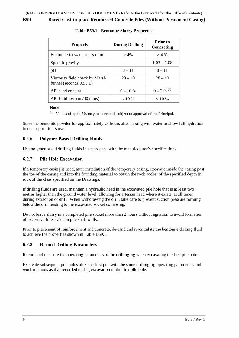
Unless specified otherwise by the manufacturer, bentonite slurry properties must be in accordance with Table B59.1.
(RMS COPYRIGHT AND USE OF THIS DOCUMENT - Refer to the Foreword after the Table of Contents)
B59 Bored Cast-in-place Reinforced Concrete Piles (Without Permanent Casing)
6 Ed 5 / Rev 1
Table B59.1 - Bentonite Slurry Properties
Property During Drilling Prior to Concreting
Bentonite-to-water mass ratio ≥ 4% < 4 %
Specific gravity 1.03 – 1.08
pH 8 – 11 8 – 11
Viscosity field check by Marsh funnel (seconds/0.95 L)
28 – 40 28 – 40
API sand content 0 – 10 % 0 – 2 % (1)
API fluid loss (ml/30 mins) ≤ 10 % ≤ 10 %
Note: (1) Values of up to 5% may be accepted, subject to approval of the Principal.
Store the bentonite powder for approximately 24 hours after mixing with water to allow full hydration to occur prior to its use.
6.2.6 Polymer Based Drilling Fluids
Use polymer based drilling fluids in accordance with the manufacturer’s specifications.
6.2.7 Pile Hole Excavation
If a temporary casing is used, after installation of the temporary casing, excavate inside the casing past the toe of the casing and into the founding material to obtain the rock socket of the specified depth in rock of the class specified on the Drawings.
If drilling fluids are used, maintain a hydraulic head in the excavated pile hole that is at least two metres higher than the ground water level, allowing for artesian head where it exists, at all times during extraction of drill. When withdrawing the drill, take care to prevent suction pressure forming below the drill leading to the excavated socket collapsing.
Do not leave slurry in a completed pile socket more than 2 hours without agitation to avoid formation of excessive filter cake on pile shaft walls.
Prior to placement of reinforcement and concrete, de-sand and re-circulate the bentonite drilling fluid to achieve the properties shown in Table B59.1.
6.2.8 Record Drilling Parameters
Record and measure the operating parameters of the drilling rig when excavating the first pile hole.
Excavate subsequent pile holes after the first pile with the same drilling rig operating parameters and work methods as that recorded during excavation of the first pile hole.

(RMS COPYRIGHT AND USE OF THIS DOCUMENT - Refer to the Foreword after the Table of Contents)
Bored Cast-in-place Reinforced Concrete Piles (Without Permanent Casing) B59
Ed 5 / Rev 1 7
6.3 FINAL PILE TOE LEVEL AND PILE HOLE CLEANING
6.3.1 Direction by Geotechnical Engineer
The attending Geotechnical Engineer will direct the Piling Supervisor as to when ground or rock of the class specified on the Drawings has been reached, the extent of further excavation required to form the socket in accordance with the Drawings, and when the pile hole and socket are considered to be clean.
6.3.2 Further Excavation
After excavation of the pile hole in accordance with Clause 6.3.1, the Principal will either accept the level reached as the final pile toe level or direct that excavation be continued to a lower level.
Where excavation to a lower level is directed, carry out further pile hole excavation to the new level directed, including further driving or sinking of the temporary casing if practicable and if necessary without damaging the casing, and again clean the pile hole in accordance with Clause 6.3.3.
6.3.3 Side Wall Roughening and Base Cleaning
Roughen the side walls of the rock socket to remove debris and surface smear and expose intact rock.
After roughening the side walls, clean the base of the pile so that intact rock is exposed over the pile base.
6.3.4 Acceptance of Pile Hole
Upon completion of excavation of the pile hole, submit to the Principal quality records, signed by the Piling Supervisor, demonstrating that the pile hole has been excavated to the position, size and level shown on the Drawings or in accordance with the directions of the attending Geotechnical Engineer, and that the soil design parameters shown on the Drawings has been achieved.
HOLD POINT
Process Held: Completion of cleaning of pile hole.
Submission Details: Notification that the pile hole excavation is complete, and documentation verifying that the plan position, size and alignment of the casing and the pile hole will result in a pile that conforms to the specified tolerances and other requirements of the Drawings and this Specification.
Release of Hold Point: The Principal will consider the submitted documents, review the progress of the Works and will either accept the pile hole excavation, or direct you to provide access for indirect examination of the pile hole (refer Clause 7), or direct you to continue excavation (refer Clause 6.3.2), prior to authorising the release of the Hold Point.
Following acceptance of the pile hole by the Principal, keep the pile hole sides and base in a clean and stable condition without contamination or softening, until concrete is placed. Place the steel reinforcement and concrete as soon as practical following final socket cleaning, and within 24 hours of the excavation of the pile hole.
Where there is a delay of more than 6 hours between cleaning and concrete placement, undertake further cleaning prior to placement of reinforcement which is to be immediately followed by placement of concrete.

(RMS COPYRIGHT AND USE OF THIS DOCUMENT - Refer to the Foreword after the Table of Contents)
B59 Bored Cast-in-place Reinforced Concrete Piles (Without Permanent Casing)
8 Ed 5 / Rev 1
7 INDIRECT EXAMINATION OF PILE HOLE To verify conformity with Clause 6.3, provide all equipment (other than that stated below) and personnel necessary for the Principal to indirectly examine the pile hole from top to bottom, including the socket base and sidewalls.
The Principal will provide the equipment for indirect examination of the pile hole, e.g. mirrors, probes, plumb weights, bright lights, CCTV cameras.
Verify conformity of the depth of each pile hole using a weighted tape at least at three locations. Carry out further indirect examination as required.
8 REINFORCEMENT Fix and place the reinforcement for the piles in accordance with Specification RMS B80 and this Specification.
Use templates when fabricating the reinforcement cages to ensure that the required reinforcement distribution is maintained.
The spacers attached to the cage must be of an approved type and distribution capable of providing the specified concrete cover and maintaining the cage in the specified position, over the whole length of the pile, after placement and during concreting.
Where telescopic casing is used, the cage must be centralised and that the minimum concrete cover must be not less than the specified value.
Cages for raked piles must incorporate provision for inserting and removing the tremie pipe without the risk of it being snagged.
Clean the pile hole and reinforcement cage of all loose and adhering material before and after the reinforcement cage is placed.
HOLD POINT
Process Held: Placing steel reinforcement cage in pile hole.
Submission Details: Verification that the pile hole is clean, and that all loose materials have been cleaned from the reinforcement cage.
Release of Hold Point: The Principal will review the submitted documents and may carry out further surveillance and audit, prior to authorising the release of the Hold Point.
WITNESS POINT
Process to be Witnessed: Inspection of the reinforcement cage prior to placing into the pile hole.
Submission Details: Submit to the Principal a works program that allows at least 2 hours advance notice of the proposed placement of the reinforcement cage into the pile hole.
(RMS COPYRIGHT AND USE OF THIS DOCUMENT - Refer to the Foreword after the Table of Contents)
Bored Cast-in-place Reinforced Concrete Piles (Without Permanent Casing) B59
Ed 5 / Rev 1 9
9 CONCRETE
9.1 GENERAL
At the time of concrete placement, the pile hole side walls and base must be clean and conform to the design parameters specified on the Drawings.
Commence concreting the pile within 2 hours of the release of the Hold Point in Clause 8. At any time where the 2 hour requirement is not met, the authorised release of the Hold Point may become invalid in which case the same Hold Point will be re-imposed.
9.2 DEWATERING
Where dewatering of the pile hole is practical, place the concrete using a centrally placed rigid hopper and pipe to a depth that will ensure the concrete does not hit the reinforcing cage and segregate.
Where dewatering is not practical, place the concrete using tremie methods in a continuous process from the base to the top of the pile. Stir up any sediment in the pile hole into suspension immediately before placing the concrete.
9.3 CONCRETE SUPPLY
Unless specified otherwise in this Specification, deliver and place concrete for the piles in accordance with RMS B80.
Provide a continuous supply of concrete so that each pile is concreted in one uninterrupted operation.
The tremie concrete mix must be self-compacting, with a nominated slump not less than 180 mm and not more than 220 mm, and in accordance with RMS B80. The tolerance on these slumps is ± 40 mm.
Verify by calculations that the working time to completely fill the pile hole with concrete is within the mix reversion time. When calculating the mix reversion time, base it on concrete at the lower limit of the permitted slump range.
9.4 CONCRETE PLACING
Where a concrete pump is used, a flexible rubber hose may be used to transport the concrete between the pump and the hopper. The hose must be long enough with sufficient support to carry the concrete to the hopper when it is raised to the highest level at the end of concreting.
Do not discharge concrete directly from the concrete pump or its discharge hose into the pile hole; use the hopper and pipe for this purpose.
The hopper and pipe of the tremie must be clean and the joints watertight throughout. Seal the tremie pipe with a plate taped to its outlet, to prevent contamination of the first charge of concrete. Alternatively, use a suitable segregation barrier such as a vermiculite plug placed in the tremie or a greased rubber ball, immediately before concrete placement. Extend the tremie pipe to the base of the pile hole before the tremie is charged with concrete.
The concrete must be of a consistency and be placed such that pockets of air or water or ground materials are not entrapped in the concrete, and the space between the reinforcement and the sides of the pile hole are completely filled with concrete.

(RMS COPYRIGHT AND USE OF THIS DOCUMENT - Refer to the Foreword after the Table of Contents)
B59 Bored Cast-in-place Reinforced Concrete Piles (Without Permanent Casing)
10 Ed 5 / Rev 1
At the start of concreting, position the outlet of the tremie pipe at the base of the pile hole. Throughout the concreting, keep the outlet of the tremie pipe a minimum distance of two metres below the top surface of the concrete by lifting the tremie pipe as the concrete level rises until the concrete surface level is above the cut-off level.
Continue concreting until sound concrete appears a minimum of 400 mm above the required pile cut-off level, to avoid defective concrete at or below cut-off level.
9.5 CONCRETING RECORDS
During concreting, maintain a record of the depth of the tremie outlet, the level of the concrete in the pile hole, and the corresponding volume of concrete placed.
9.6 CASING EXTRACTION
Withdraw any temporary casing whilst the concrete is still fluid at close to the original slump.
Where a temporary casing is being extracted during concreting, maintain a sufficient head of concrete within it to counter external pressure from the surrounding ground material so that the concrete forming the minimum cover to the reinforcement is not contaminated in any way.
Maintain the direction of pull on the temporary casing along the axis of the pile. Withdraw the casing slowly during concreting at a rate and in a manner such that no significant disturbance is caused to the surrounding material and that the pile hole is completely filled up with concrete to the exclusion of any voids. Do not withdraw the last section of casing until the concreting operation is completed.
Vibrating casing extractors may be used subject to compliance with statutory regulations (e.g. noise and vibration control) and the Conditions of Contract regarding protection of persons and property.
10 CUT-OFF AND CLEAN UP OF TOP OF PILE Carefully remove any concrete and/or casing above the cut-off level without damaging the permanent work not earlier than 24 hours after completion of placement of concrete.
Cut back the concrete of the pile so that the top of the pile embedded in the substructure is undamaged, sound, free of laitance and any loose material and has a profile with surface roughness not less than 3 mm.
The reinforcement protruding from the pile must be kept clean and protected from rusting and damage.
11 PILE LOAD TESTING
11.1 GENERAL
Where specified on the Drawings, carry out pile load testing to confirm pile design parameters. The required pile test load is specified on the Drawings and is dependent on the extent of pile testing as specified on the Drawings. Carry out the tests specified on the Drawings on the nominated test piles.
Additional performance criteria for load testing, if required, must be as specified on the Drawings.
(RMS COPYRIGHT AND USE OF THIS DOCUMENT - Refer to the Foreword after the Table of Contents)
Bored Cast-in-place Reinforced Concrete Piles (Without Permanent Casing) B59
Ed 5 / Rev 1 11
Unless specified otherwise by the Principal, perform static or high-strain dynamic testing in accordance with AS 2159, and Clause 11.2 of this Specification where applicable.
Other types of pile load testing in accordance with AS 2159 may be used, where approved by the Principal.
11.2 HIGH-STRAIN DYNAMIC TESTING
11.2.1 General
Where high-strain dynamic pile testing is to be carried out, extend the pile as required to allow the attachment of transducers or similar testing instruments.
Carry out high-strain dynamic testing in accordance with this Clause and AS 2159 using an approved organisation with approved equipment using an approved dynamic testing system, with subsequent wave equation analysis or signal matching carried out using an approved computer program, all as listed in the “Lists of RMS Approved Bridge Components and Systems” at: http://www.rms.nsw.gov.au/business-industry/partners-suppliers/documents/tenders-contracts/listofapprovedbridgecomponentssystems.pdf.
Testing must not result in the allowable concrete stresses being exceeded.
11.2.2 Testing Procedure
Use the following testing procedure:
(a) Attach four bolt-on transducers to the pile at a minimum of 1.5 times the maximum pile width below the head of the pile in accordance with the requirements of the system supplier.
(b) Following the connection of the transducers to the analyser, strike the pile with sufficient energy to verify the required resistance.
Record the blow counts, measured resistance and nominal and measured driving energy.
The relationship between the nominal driving energy and blow counts determined from a dynamic test is only valid for the specific combination of hammer, helmet, cushion, pile rake, pile size, pile material and founding material.
11.2.3 Dynamic Analysis
Analyse the dynamic test results for each pile tested. Analyses must include full Dynamic Analysis using measured field parameters of the test data (e.g. CAPWAP) and resistance versus blow count curves (e.g. GRLWEAP analysis), when requested by the Principal, showing a minimum of six (6) different resistances and the corresponding blow counts.
11.2.4 Report
Provide to the Principal two copies of a report for each pile tested including:
(a) Complete PDA (or approved equivalent) output for all blows, including driving stresses and net driving energy;
(b) CAPWAP (or approved equivalent) analyses for selected blows;
(c) When requested by the Principal, GRLWEAP (or approved equivalent) output in the form of resistance versus blow count curves giving the true pile resistance for specific driving energies, using data measured during the high-strain dynamic testing;

(RMS COPYRIGHT AND USE OF THIS DOCUMENT - Refer to the Foreword after the Table of Contents)
B59 Bored Cast-in-place Reinforced Concrete Piles (Without Permanent Casing)
12 Ed 5 / Rev 1
(d) Certification that the pile has been dynamically tested in accordance with this Specification. If it is not possible for this certification to be provided due to nonconformities in the testing or the pile tested, provide instead an itemised nonconformity report together with the proposed disposition.
12 PILE INTEGRITY TESTING Pile integrity testing must be capable to confirm that the pile is sound over its full length. Carry out integrity testing on all piles nominated on the Drawings and assess pile integrity in accordance with AS 2159.
(RMS COPYRIGHT AND USE OF THIS DOCUMENT - Refer to the Foreword after the Table of Contents)
Bored Cast-in-place Reinforced Concrete Piles (Without Permanent Casing) B59
Ed 5 / Rev 1 13
ANNEXURE B59/A – (NOT USED)
ANNEXURE B59/B – PAYMENT Refer to Clause 1.2.1.
In the Schedule of Prices accompanying the Lump Sum Tender, the cost of piles is divided into the following items or sub-items (separately provide similar items or sub-items for each diameter of pile):
(a) Drilling/Test Coring Prior to Pile Excavation - Provisional Quantity
(i) Drilling from Ground Level to Start of Rock Coring
The unit of measurement is per lineal metre of coring down to the level at which rock coring commences. The level is at one (1) metre above the level at which shaft resistance is required (refer Clause 5).
(ii) Rock Coring
The unit of measurement is per lineal metre of coring and sampling within the required zone. This item includes the costs of obtaining the cores, logging them and placing the cores in core boxes.
The end of rock coring is at the depth that is at least 3 metres or 3 pile diameters, whichever is the greater, below the pile Contract Level (refer Clause 5).
(b) Attendance of Professional Geotechnical Engineer During Pile Hole Excavation
The unit of measurement is per hour of attendance on site in accordance with Clause 6.1.2.
(c) Excavation of Pile Hole Including Temporary Casing
(i) To Contract Level
This item includes the cost of excavation to the Contract Levels shown on the Drawings, including the installation and splicing of temporary casing, sealing and dewatering if necessary of the pile hole, removal of excavated material from site, preparations for and attendance on any indirect examination of the pile hole and cutting off to suit the pile cap construction.
The unit of measurement is per lineal metre of pile hole.
(ii) Below Contract Level - Provisional Quantity
This item includes the cost of excavating below the Contract Levels shown on the Drawings, including the use of temporary casing, sealing and dewatering of the pile hole, removal of excavated material from site, and preparations for and attending any indirect examination of the pile hole.
The unit of measurement is per lineal metre of pile hole.
(RMS COPYRIGHT AND USE OF THIS DOCUMENT - Refer to the Foreword after the Table of Contents)
B59 Bored Cast-in-place Reinforced Concrete Piles (Without Permanent Casing)
14 Ed 5 / Rev 1
(d) Provision for Indirect Examination of Pile Hole
(i) For Indirect Visual or Other Inspection Method
This item includes the supply of plant, equipment, e.g. planks and barriers, and personnel to allow the Principal to indirectly examine the pile hole by indirect visual or other inspection method.
The unit of measurement is per each pile hole indirectly examined.
(ii) For CCTV Indirect Examination Method - Provisional Quantity
This item includes the supply of plant, equipment including 240 V AC power supply, planks and barriers, and personnel to allow the Principal to indirectly examine the pile hole by CCTV camera.
The unit of measurement is per each pile hole indirectly examined.
(e) Supply and Placement of Reinforcement
(i) To Contract Level
The unit of measurement is per tonne of reinforcement placed to the Contract Levels shown on the Drawings.
(ii) Below Contract Level - Provisional Quantity.
The unit of measurement is per tonne of reinforcement placed below the Contract Level shown on the Drawings.
(f) Supply and Placement of Concrete
(i) To Contact Level
This item includes the cost of supply and placement of concrete to the Contract Levels shown on the Drawings.
The unit of measurement is per lineal metre of pile.
(ii) Below Contract Level - Provisional Quantity.
This item includes the cost of supply and placement of concrete below the Contract Levels shown on the Drawings.
The unit of measurement is per lineal metre of pile.
(g) Pile Integrity Testing
(i) Pile Integrity Testing
This item covers all costs associated with undertaking the contract integrity pile testing in accordance with Clause 12, including construction and removal of any temporary measures required to undertake the testing.
The unit of measurement is per “each” pile tested.
(RMS COPYRIGHT AND USE OF THIS DOCUMENT - Refer to the Foreword after the Table of Contents)
Bored Cast-in-place Reinforced Concrete Piles (Without Permanent Casing) B59
Ed 5 / Rev 1 15
(ii) Additional Pile Integrity Testing - Provisional Quantity
This item covers all costs associated with undertaking additional integrity pile testing in accordance with Clause 12 when testing is instructed by the Principal. This item includes the cost of construction and removal of any temporary measures required to undertake the testing.
The unit of measurement is per “each” pile tested.
(h) Pile Load Testing
(i) Site Establishment
This item covers all costs associated with establishing on site and the subsequent removal of the testing equipment at each bridge site. No additional payment will be made for relocation of the testing equipment within each bridge site.
The unit of measurement is per “each” establishment of the testing equipment on site at each bridge location.
(ii) Pile Testing
This item covers all costs associated with undertaking the contract pile load testing in accordance with Clause 11, including construction and removal of any temporary measures required to undertake the testing, any excavation and backfilling required to undertake the test, and the preparation and submission of the test result reports.
The unit of measurement is per “each” pile tested.
(iii) Additional Pile Testing - Provisional Quantity
This item covers all costs associated with undertaking additional load pile testing in accordance with Clause 11 when testing is instructed by the Principal to verify design strength. The item includes cost associated with construction and removal of any temporary measures required to undertake the testing, any excavation and backfilling required to undertake the test, and the preparation and submission of the test result reports.
The unit of measurement is per “each” pile tested.

(RMS COPYRIGHT AND USE OF THIS DOCUMENT - Refer to the Foreword after the Table of Contents)
B59 Bored Cast-in-place Reinforced Concrete Piles (Without Permanent Casing)
16 Ed 5 / Rev 1
ANNEXURE B59/C – SCHEDULES OF HOLD POINTS, WITNESS POINTS AND IDENTIFIED RECORDS
Refer to Clause 1.2.2.
C1 SCHEDULE OF HOLD POINTS AND WITNESS POINTS
Clause Type Description
3 Hold Certification that piling equipment and method under the proposed set up and site conditions will be used within its safe working capacities.
6.3.4 Hold Acceptance of pile hole.
8 Hold Placing of steel reinforcement cage in pile hole.
8 Witness Inspection of reinforcement cage prior to and during placing into pile hole.
C2 SCHEDULE OF IDENTIFIED RECORDS
The records listed below are Identified Records for the purposes of RMS Q Annexure Q/E.
Clause Description of Identified Record
6.3.4 Piling records, signed by Piling Supervisor, verifying conformity of the pile hole upon completion of its excavation.
7 Results of pile hole examination.
9.5 Records of tremie outlet depth, concrete level in the pile hole and volume of concrete placed during concreting.
11.2.4 Pile load testing results.
12 Pile integrity testing results.
(RMS COPYRIGHT AND USE OF THIS DOCUMENT - Refer to the Foreword after the Table of Contents)
Bored Cast-in-place Reinforced Concrete Piles (Without Permanent Casing) B59
Ed 5 / Rev 1 17
ANNEXURE B59/D – PLANNING DOCUMENTS Refer to Clause 1.2.3.
The following documents are a summary of documents that must be included in the PROJECT QUALITY PLAN. Review the requirements of this Specification and other contract documents to determine any additional documentation requirements.
(a) Equipment and methods for installing temporary casing and excavating pile hole (refer to Clauses 3 and 6.2.1);
(b) Method for overcoming obstructions to driving of temporary casing, if applicable (refer to Clause 6.2.2);
(c) Type of drilling fluid and method of maintaining its properties, if applicable (refer to Clauses 6.2.4 to 6.2.6);
(d) Method of sealing and cleaning base and sides of pile hole (refer to Clause 6.3.3);
(e) Method of supporting reinforcement cage (refer to Clause 8);
(f) Details of mix design for tremie concrete (refer to Clause 9.3);
(g) Method of placing concrete including method of inserting and withdrawing tremie pipe (refer to Clause 9.4);
(h) Method of extracting temporary casing (refer to Clause 9.6).
ANNEXURES B59/E TO B59/K – (NOT USED)
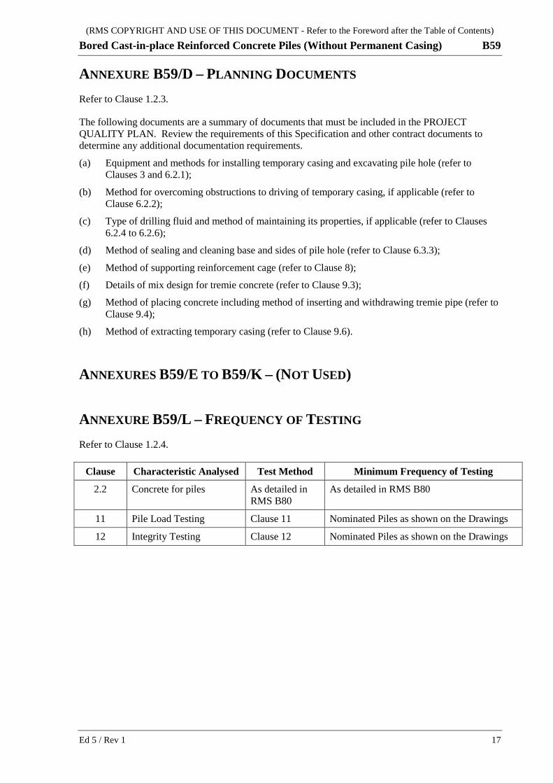
ANNEXURE B59/L – FREQUENCY OF TESTING Refer to Clause 1.2.4.
Clause Characteristic Analysed Test Method Minimum Frequency of Testing
2.2 Concrete for piles As detailed in RMS B80
As detailed in RMS B80
11 Pile Load Testing Clause 11 Nominated Piles as shown on the Drawings
12 Integrity Testing Clause 12 Nominated Piles as shown on the Drawings

(RMS COPYRIGHT AND USE OF THIS DOCUMENT - Refer to the Foreword after the Table of Contents)
B59 Bored Cast-in-place Reinforced Concrete Piles (Without Permanent Casing)
18 Ed 5 / Rev 1
ANNEXURE B59/M – REFERENCED DOCUMENTS Refer to Clause 1.2.5.
RMS Specifications
RMS G22 Work Health and Safety (Construction and Maintenance Works)
RMS G36 Environmental Protection
RMS Q Quality Management System
RMS B80 Concrete Work For Bridges
RMS 3211 Cements, Binders and Fillers
RMS Test Methods
RMS T375 Sampling and Testing of Grout
Australian Standards
AS 1726 Geotechnical site investigations
AS 2159 Piling – Design and installation
AS 5100 Bridge design
AS 5100.3 Part 3: Foundations and soil-supporting structures