boot mode index - infineon technologies
TRANSCRIPT

BMIBoot Mode IndexXMC™ microcontrollersSeptember 2016

Agenda
Overview
Key feature: Start-up mode selection requires no pins
Key feature: BMI change supported by ROM routine
System integration
Application examples
Additional features
1
2
3
4
5
6
2Copyright © Infineon Technologies AG 2016. All rights reserved.
Agenda
Overview
Key feature: Start-up mode selection requires no pins
Key feature: BMI change supported by ROM routine
System integration
Application examples
Additional features
1
2
3
4
5
6
3Copyright © Infineon Technologies AG 2016. All rights reserved.

BMIBoot Mode Index
Highlights
The BMI value determines the start-upmode and debug configuration of theXMC1000. Bootstrap modes via UART orSPI as well as single pin debug or SWDare supported. Setting the BMI to "UserProductive Mode" disables all interfacesto safeguard the XMC1000 againstexternal accesses.
Customer benefitsKey features
› More pins available for customerapplication usage
› Easy change of BMI throughcustomer application code
› Start-up mode selection requiresno pins
› BMI change supported by ROMroutine
User mode HAR(SWD/SPD)
User mode debug
User Productive Mode
ASC_BSL
SSC_BSL
Boot Mode Index
(SWD/SPD)
4Copyright © Infineon Technologies AG 2016. All rights reserved.

Agenda
Overview
Key feature: Start-up mode selection requires no pins
Key feature: BMI change supported by ROM routine
System integration
Application examples
Additional features
1
2
3
4
5
6
5Copyright © Infineon Technologies AG 2016. All rights reserved.
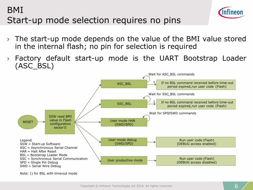
BMIStart-up mode selection requires no pins
› The start-up mode depends on the value of the BMI value storedin the internal flash; no pin for selection is required
› Factory default start-up mode is the UART Bootstrap Loader(ASC_BSL)
User mode HAR(SWD/SPD)
User mode debug(SWD/SPD)
Run user code (Flash)(DEBUG access enabled)
User productive modeRun user code (Flash)
(DEBUG access disabled)
ASC_BSL
RESET
Wait for SPD/SWD commands
Wait for ASC_BSL commands
SSW read BMIvalue in Flashconfiguration
sector 0
Legend:SSW = Start-up SoftwareASC = Asynchronous Serial ChannelHAR = Halt After ResetBSL = Bootstrap Loader ModeSSC = Synchronous Serial CommunicationSPD = Single Pin DebugSWD = Serial Wire Debug
Note: 1) for BSL with time-out mode
SSC_BSL
If no BSL command received before time-out-period expired,run user code (Flash)
Wait for SSC_BSL commands
If no BSL command received before time-out-period expired,run user code (Flash)
1
1
6Copyright © Infineon Technologies AG 2016. All rights reserved.

Agenda
Overview
Key feature: Start-up mode selection requires no pins
Key feature: BMI change supported by ROM routine
System integration
Application examples
Additional features
1
2
3
4
5
6
7Copyright © Infineon Technologies AG 2016. All rights reserved.

BMIBMI change supported by ROM routine
› BMI programing is supported by a ROM routine located at0x00000108 and can be accessed in the following way:
#define _BmiInstallationReq (0x00000108)#define XMC1000_BmiInstallationReq (*((unsigned long (**)(unsigned short)) _BmiInstallationReq))XMC1000_BmiInstallationReq(0xFFC0); // BMI = ASC_BSL
Start-up mode Pins used BMI value
ASC Bootstrap Load Mode(ASC_BSL)
P0.14/P0.15
or P1.3/P1.2
0xFFC0
User Mode (Productive) - 0xF8C1
User Mode (Debug) SWD0 P0.14/P0.15 0xF8C3
User Mode (Debug) SWD1 P1.3/P1.2 0xFAC3
User Mode (Debug) SPD0 P0.14 0xF9C3
User Mode (Debug) SPD1 P1.3 0xFBC3
User Mode (HAR) SWD0 P0.14/P0.15 0xF8C7
User Mode (HAR) SWD1 P1.3/P1.2 0xFAC7
User Mode (HAR) SPD0 P0.14 0xF9C7
User Mode (HAR) SPD1 P1.3 0xFBC7
8Copyright © Infineon Technologies AG 2016. All rights reserved.

Agenda
Overview
Key feature: Start-up mode selection requires no pins
Key feature: BMI change supported by ROM routine
System integration
Application examples
Additional features
1
2
3
4
5
6
9Copyright © Infineon Technologies AG 2016. All rights reserved.

BMISystem integration
› Target applications
– Motor control
– Intelligent lighting
– Power conversion
– Human machine interface
– Touch sense
– Connectivity
– General purpose
During mass production stage, the
device will most probably programmed
to “Productive mode” for flash protection
of the application code.
For field update of the flash content the
“Productive mode” can be changed back
to another start-up mode by the
application code at any time.
E.g. the application code could provide a
feature for changing the BMI back to
ASC_BSL mode when receiving a special
command via UART or triggered by an
external signal via a GPIO pin.
XMC1200 XMC1300XMC1100
●● ●ROM routine
XMC1000_BmiInstallationReq (BMI)
BMI Register
write
Communication
GPIO, InterruptApplicationCode
call
FLASH
10Copyright © Infineon Technologies AG 2016. All rights reserved.

Agenda
Overview
Key feature: Start-up mode selection requires no pins
Key feature: BMI change supported by ROM routine
System integration
Application examples
Additional features
1
2
3
4
5
6
11Copyright © Infineon Technologies AG 2016. All rights reserved.

Application examplesUse cases of the start-up modes
Use caseStart-up mode
› Bootstrap Loader mode (ASC_BSL,SSC_BSL)
› User mode with debug enabled(UMD)
› User mode with debug enabled andHalt After Reset (UMHAR)
› User Productive Mode (UPM)
› Allows easy and quickprogramming/erasing of the flash bycode downloaded into the SRAM viaUART or SPI
› The user code is executed afterpower-up. A debugger can connect tothe device at any time via SWD orSPD
› SWD is a standard debug protocolfor ARM® Cortex™ microcontrollers
› SPD is Infineon propriety debugprotocol allowing Single Pin Debug
› User code execution in flash must bestarted by the debugger
› Flash protection scheme. Debuggercannot connect to device and accessthe Flash content
12Copyright © Infineon Technologies AG 2016. All rights reserved.

Agenda
Overview
Key feature: Start-up mode selection requires no pins
Key feature: BMI change supported by ROM routine
System integration
Application examples
Additional features
1
2
3
4
5
6
13Copyright © Infineon Technologies AG 2016. All rights reserved.

BMIProgramming and debugging pin
› Two sets of pins available for programming and debugging:
– Channel 0 supports all start-up modes including SSC_SCL
– Channel 1 supports full and half duplex ASC_BSL, SWDand SPD
P0.14
P0.15
P1.3
P1.2
Channel 0
Channel 1
RXD SWDIO SPD RxD-TxD (Half duplex) SCLK
TXD SWDCLK - -
TXD SWDCLK - - MRST-MTSR
RXD SWDIO SPD
XMC1000
P0.13- - - - /CS
ASC_BSL
(Full duplex )
User Mode
SWD0/1
ASC_BSL
(Half duplex )
User Mode
SPD0/1SSC_BSL
RxD-TxD (Half duplex)
14Copyright © Infineon Technologies AG 2016. All rights reserved.

BMIUser Productive Mode (1/2)
› BMI=0xF8C1
› This mode should only be used if the user has confirmed thatthe code is FULLY TESTED and NO MORE MODIFICATIONof code is required
› After changing to “User Productive Mode” and a new power-upthe user code will start to run at the address contained at theflash location 0x10001004
› “User Productive Mode” provides indirectly MEMORYPROTECTION by not allowing external tools, e.g. debugger andFlash Programming Tools to access (read/write) the device
15Copyright © Infineon Technologies AG 2016. All rights reserved.

BMIUser Productive Mode (2/2)
› There is no external access to the device once it isprogrammed to “User Productive Mode”, unless there is aspecific routine already embedded in user code
› This specific routine has to be called under user-definedconditions, e.g. via interrupt or GPIO pins latch values
› The specific routine calls theXMC1000_BmiInstallationReq(new BMI) routine to re-programa new BMI value
› For code protection purpose, changing from “User ProductiveMode” and any other mode, the start-up software will erasethe full flash of the device and re-install the default BMI ->ASC_BSL (UART-BSL). Hence, user needs to call the BMI re-programming routine again via the UART-BSL mode if that isnot the desired start-up mode
16Copyright © Infineon Technologies AG 2016. All rights reserved.
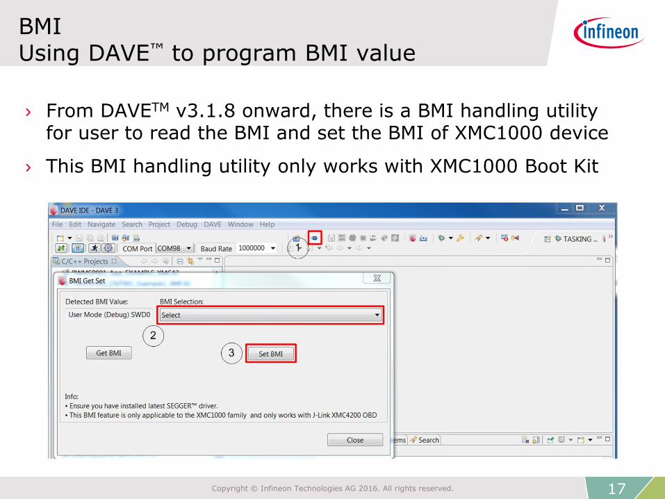
BMIUsing DAVE™ to program BMI value
› From DAVETM v3.1.8 onward, there is a BMI handling utilityfor user to read the BMI and set the BMI of XMC1000 device
› This BMI handling utility only works with XMC1000 Boot Kit
17Copyright © Infineon Technologies AG 2016. All rights reserved.

BMIAdditional note on programming the BMI value
› The default boot mode for XMC1000 device is UART-BSL mode
› A master reset will be executed after BMI value is updatedSwitching off the supply voltage before Master reset happenwill cause the BMI value to change to default BMI -> ASC_BSL
› The VDDP should keep stable at operating voltage of XMC1000during the programming of BMI value. The time taken fromcalling the XMC1000_BmiInstallationReq(new BMI) routine tillthe BMI value is changed after the master reset is about10 msec @ MCLK 8 MHz
18Copyright © Infineon Technologies AG 2016. All rights reserved.

› Product Briefs
› Selection Guides
› Application Brochures
› Presentations
› Press Releases, Ads
› Application Notes
› Technical Articles
› Simulation Models
› Datasheets, MCDS Files
› PCB Design Data
› Technical Videos
› Product Information
Videos
› Forums
› Product Support
Support material
Collaterals and
Brochures
Technical Material
Videos
Contact
› www.infineon.com/XMC
› www.infineon.com/XMC
› Kits and Boards
› DAVETM
› Software and Tool Ecosystem
› Infineon Media Center
› XMC Mediathek
› Infineon Forums
› Technical Assistance Center (TAC)
19Copyright © Infineon Technologies AG 2016. All rights reserved.

The information given in this training materials is given as a hint forthe implementation of the Infineon Technologies component only andshall not be regarded as any description or warranty of a certainfunctionality, condition or quality of the Infineon Technologiescomponent.
Infineon Technologies hereby disclaims any and all warranties andliabilities of any kind (including without limitation warranties of non-infringement of intellectual property rights of any third party) withrespect to any and all information given in this training material.
Disclaimer

21