book 18 edition 1.0 july 2018 - zhagastandard.org · figure 1-1: 3d-drawings of the luminaire...
TRANSCRIPT
Book 18 Edition 1.0 July 2018
Luminaire Extension Module & Receptacle

Zhaga Interface Specification Book 18
Summary (informative)
Background The Zhaga Consortium is a global lighting-industry organization that aims to standardize components of LED luminaires, including LED light engines, LED modules, LED arrays, holders, electronic control gear (LED drivers) and connectivity fit systems.
Zhaga has created a set of interface specifications, known as Books. Each Book defines one or more components of an LED luminaire by means of the mechanical, photometric, electrical, thermal, and control interfaces of the component to its environment. This makes such products interchangeable in the sense that it is easy to replace one product with another, even if they have been made by different manufacturers.
Contents This Book 18 defines the mechanical and electrical interface between a Luminaire Extension Receptacle on the one hand and the Luminaire Extension Module or Luminaire Extension Cap on the other hand. These components are typically applied in outdoor lighting applications. This Book should be read together with Zhaga Book 1.
Intended Use The luminaire extension module, luminaire extension cap and luminaire extension receptacle defined in this Book 18 are intended to be installed and replaced by professionals only.

COPYRIGHT
The Zhaga Interface Specification is published by the Zhaga Consortium, and has been prepared by the members of the Zhaga Consortium. All rights are reserved. Reproduction in whole or in part is prohibited without express and prior written permission of the Zhaga Consortium.
DISCLAIMER
The information contained herein is believed to be accurate as of the date of publication. However, neither the Zhaga Consortium, nor any member of the Zhaga Consortium will be liable for any damages, including indirect or consequential, from use of the Zhaga Interface Specification or reliance on the accuracy of this document.
CLASSIFICATION
The information contained in this document is for public use.
NOTICE
For any further explanation of the contents of this document, or in case of any perceived inconsistency or ambiguity of interpretation, visit www.zhagastandard.org or contact [email protected].

Zhaga Interface Specification Book 18: Luminaire Extension Module & Receptacle Edition 1.0
© Zhaga Consortium, July 2018 i
Table of Contents 1 General ................................................................................................................... 5
1.1 Introduction ............................................................................................................................................................................... 5 1.2 Scope ............................................................................................................................................................................................. 5 1.3 Conformance and references.............................................................................................................................................. 5
1.3.1 Conformance ................................................................................................................................................................... 5 1.3.2 References ........................................................................................................................................................................ 6
1.4 Definitions................................................................................................................................................................................... 6 1.5 Acronyms .................................................................................................................................................................................... 6 1.6 Symbols ........................................................................................................................................................................................ 6 1.7 Conventions ............................................................................................................................................................................... 6
1.7.1 Precedence ....................................................................................................................................................................... 6 1.7.2 Cross references ............................................................................................................................................................ 6 1.7.3 Informative text ............................................................................................................................................................. 7 1.7.4 Terms in capitals ........................................................................................................................................................... 7 1.7.5 Units of physical quantities ...................................................................................................................................... 7 1.7.6 Decimal separator ......................................................................................................................................................... 7 1.7.7 Limits .................................................................................................................................................................................. 7
2 Overview (Informative) ................................................................................... 8 2.1 General ......................................................................................................................................................................................... 8 2.2 Description of the Luminaire Extension Module, Cap and Receptacle ............................................................ 8 2.3 Outline of this Book ................................................................................................................................................................ 8
Part 1: Interface Definition
3 Mechanical interface ...................................................................................... 11 3.1 Drawing principles ............................................................................................................................................................... 11 3.2 Mechanical references ........................................................................................................................................................ 11 3.3 Definition of the mechanical interface of the Luminaire Extension Module .............................................. 12 3.4 Definition of the mechanical interface of the Luminaire Extension Cap...................................................... 16 3.5 Definition of the mechanical interface of the Luminaire Extension Receptacle ....................................... 16 3.6 Definition of the mechanical interface of the Luminaire .................................................................................... 18
4 Electrical interface .......................................................................................... 20 4.1 Electrical interface to the Luminaire Extension Module ..................................................................................... 20 4.2 Definition of the electrical interface of the Luminaire Extension Receptacle ........................................... 20
Part 2: Compliance Tests
5 Compliance test tools ..................................................................................... 22 5.1 Luminaire Extension Module test tools ...................................................................................................................... 22
5.1.1 Mechanical-stop-gauge ............................................................................................................................................ 22 5.2 Luminaire Extension Receptacle test tools ............................................................................................................... 22

Zhaga Interface Specification Book 18: Luminaire Extension Module & Receptacle Edition 1.0
© Zhaga Consortium, July 2018 ii
5.2.1 Contact-making-gauge-min ................................................................................................................................... 22 5.2.2 Contact-making-gauge-max .................................................................................................................................. 22 5.2.3 Un-mating-torque-gauge ........................................................................................................................................ 22
6 Luminaire Extension Module Compliance Tests ................................... 23 6.1 Luminaire Extension Module mechanical interface tests ................................................................................... 23
6.1.1 Test of mechanical dimensions ............................................................................................................................ 23 6.1.2 Test of LEX-M outer diameter .............................................................................................................................. 25 6.1.3 Test of the LEX-M mechanical stop features .................................................................................................. 26 6.1.4 Test of the LEX-M sealing surface ....................................................................................................................... 26 6.1.5 Test of the LEX-M contact plating ....................................................................................................................... 27
7 Luminaire Extension Cap Compliance Tests .......................................... 28 7.1 Luminaire Extension Cap mechanical interface tests ........................................................................................... 28
7.1.1 Test of mechanical dimensions ............................................................................................................................ 28 7.1.2 Test of LEX-M outer diameter .............................................................................................................................. 28 7.1.3 Test of the LEX-M mechanical stop features .................................................................................................. 28 7.1.4 Test of the LEX-M sealing surface ....................................................................................................................... 28
8 Luminaire Extension Receptacle compliance tests .............................. 29 8.1 Luminaire Extension Receptacle mechanical interface tests ............................................................................ 29
8.1.1 Test of mechanical dimensions ............................................................................................................................ 29 8.1.2 Test of the LEX-R mating & contact making ................................................................................................... 31 8.1.3 Test of the LEX-R mating and un-mating torque ......................................................................................... 31 8.1.4 Test of the LEX-R contact plating ........................................................................................................................ 32
Annex A Application guidelines ..................................................................... 33 A.1 Street lighting ......................................................................................................................................................................... 33
Annex B Mechanical drawing of the Mechanical-stop-gauge ............... 34
Annex C Mech. drawing of the Contact-making-gauge-min and Contact-making-gauge-max ............................................................................... 35
Annex D Mechanical drawing of the Un-mating-torque-gauge ............ 36
Annex E LEX-M and LEX-R mechanical interface tests (Informative) 37 E.1 LEX-M mechanical interface tests ................................................................................................................................. 37
8.1.5 Test of mechanical dimensions ............................................................................................................................ 37 E.2 LEX-R mechanical interface tests .................................................................................................................................. 37
8.1.6 Test of mechanical dimensions ............................................................................................................................ 37

Zhaga Interface Specification Book 18: Luminaire Extension Module & Receptacle Edition 1.0
© Zhaga Consortium, July 2018 iii
List of Figures Figure 1-1: 3D-drawings of the Luminaire Extension Receptacle (Top view) and the Luminaire Extension Module (bottom view) as defined in this Book 18 (Informative) ....................................................................................... 5 Figure 2-1: Luminaire Extension Module, Cap and Receptacle in a system. .................................................................. 8 Figure 3-1: Positions of the reference point, the reference plane and reference axes of the LEX-R and LEX-M. ................................................................................................................................................................................................................... 11 Figure 3-2: Mechanical interface of the LEX-M; Mating face-1. ......................................................................................... 12 Figure 3-3: Mechanical interface of the LEX-M; Mating face-2. ......................................................................................... 13 Figure 3-4: Details of the mechanical interface of the LEX-M: section B-B .................................................................. 14 Figure 3-5: Details of the mechanical interface of the LEX-M: section E-E .................................................................. 14 Figure 3-6: Details of the mechanical interface of the LEX-M: section C-C and section D-D ................................ 15 Figure 3-7: Details of the mechanical interface of the LEX-M: section F-F ................................................................... 15 Figure 3-8: Mechanical interface of the LEX-R. Details in next figure. ........................................................................... 17 Figure 3-9: Detail of the mechanical interface of the LEX-R ............................................................................................... 18 Figure 3-10: Gasket area and Keep-out area of the Luminaire ......................................................................................... 19 Figure A-1: Orientation for LEX-R and LEX-M in street lighting applications. ........................................................... 33

Zhaga Interface Specification Book 18: Luminaire Extension Module & Receptacle Edition 1.0
© Zhaga Consortium, July 2018 iv
List of Tables Table 4-1: Assignments of contacts in LEX-M and LEX-R. ................................................................................................... 20 Table 6-1: Dimension of the LEX-M and LEX-C defined in Figure 3-2. ........................................................................... 23 Table 6-2: Dimension of the LEX-M and LEX-C defined in Figure 3-3. ........................................................................... 24 Table 6-3: Dimension of the LEX-M and LEX-C defined in Figure 3-4. ........................................................................... 24 Table 6-4: Dimension of the LEX-M and LEX-C defined in Figure 3-5. ........................................................................... 25 Table 6-5: Dimension of the LEX-M and LEX-C defined in Figure 3-6. ........................................................................... 25 Table 6-6: Dimension of the LEX-M and LEX-C defined in Figure 3-7. ........................................................................... 25 Table 6-7: Pass criteria for percentage mass of several elements in the contact plating. ..................................... 27 Table 8-1: Dimension of the LEX-M and LEX-C defined in Figure 3-8. ........................................................................... 30 Table 8-2: Dimension of the LEX-M and LEX-C defined in Figure 3-9. ........................................................................... 30 Table 8-3: Pass criteria for percentage mass of several elements in the contact plating. ..................................... 32

Zhaga Interface Specification Book 18: Luminaire Extension Module & Receptacle Edition 1.0 General
© Zhaga Consortium, July 2018 5
1 General
1.1 Introduction The Zhaga Consortium is a global organization that aims to standardize components of LED Luminaires. A LED Luminaire is a lighting fixture for general lighting that contains a light source based on solid-state technology. Such light sources, including LED Modules and LED Light Engines, typically consist of one or more LEDs combined with an Electronic Control Gear (LED driver). Other components of LED luminaires include LED Arrays, Holders, and connectivity fit systems.
Zhaga has created a set of interface specifications, known as Books, which define the interfaces between a component and its environment. Book 1 is a special Book in the sense that it provides common information, which is relevant to all other Books in the series. In addition, Book 1 defines requirements and compliance tests, which are applicable across multiple Zhaga books. Such Books refer to those requirements and compliance tests as applicable.
1.2 Scope This Book 18 defines the mechanical and electrical interface between a Luminaire Extension Receptacle and the Luminaire Extension Module typically applied in outdoor lighting applications. Figure 1-1 shows an informative 3D-drawings these products.
Figure 1-1: 3D-drawings of the Luminaire Extension Receptacle (Top view) and the Luminaire Extension
Module (bottom view) as defined in this Book 18 (Informative)
1.3 Conformance and references
1.3.1 Conformance All provisions in the Zhaga interface Specifications are mandatory, unless specifically indicated as recommended, optional or informative. Verbal expressions of provisions in the Zhaga interface specifications follow the rules provided in Annex H of ISO/IEC Directives, Part 2. For clarity, the word “shall” indicates a requirement that is to be followed strictly in order to conform to the Zhaga interface specifications, and from which no deviation is permitted. The word “should” indicates that among several possibilities one is recommended as particularly suitable, without mentioning or excluding others, or that a certain course of action is preferred but not necessarily required, or that (in the negative form) a certain possibility or course of action is deprecated but not prohibited.

Zhaga Interface Specification Book 18: Luminaire Extension Module & Receptacle Edition 1.0 General
© Zhaga Consortium, July 2018 6
1.3.2 References For references that are not listed in this section, see [Book 1]. For undated references, the most recently published edition applies.
[Book 1] Zhaga Interface Specification, Book 1: Overview and Common Information.
[DALI] [DALI-part 101] & [DALI-part 102] & [DALI-part 103] & [DALI-part 207]
[DALI-part 101] IEC 62386-101:2014, Digital addressable lighting interface - Part 101: General requirements – System components, Edition 2.0, 2014-11.
[DALI-part 102] IEC 62386-102:2014, Digital addressable lighting interface - Part 102: General requirements – Control gear, Edition 2.0, 2014-11.
[DALI-part 103] IEC 62386-103:2014, Digital addressable lighting interface - Part 103: General requirements – Control devices, Edition 2.0, 2014-11.
[DALI-part 207] IEC 62386-207:2014, Digital addressable lighting interface - Part 207: Particular requirements for control gear - LED modules, 2014-11.
[IEC60598-1] IEC 60598-1; 2014, Luminaires – Part 1: General requirements and tests. Edition 8.0.
1.4 Definitions This section defines terms that have a specific meaning in the context of this Book 18. Terms that have a specific meaning across all Zhaga Books are defined in [Book 1].
Luminaire Extension Module Module according to the specifications in this book.
Luminaire Extension Cap Cap according to the specifications in this book.
Luminaire Extension Receptacle Receptacle according to the specifications in this book.
1.5 Acronyms This section defines acronyms that have a specific meaning in the context of this Book 18. Acronyms that have a specific meaning across all Zhaga Books are defined in [Book 1].
LEX-M Luminaire Extension Module
LEX-C Luminaire Extension Cap
LEX-R Luminaire Extension Receptacle
1.6 Symbols Symbols that have a specific meaning across all Zhaga Books defined in [Book 1].
1.7 Conventions This section defines the notations and conventions used in the Zhaga Interface Specifications.
1.7.1 Precedence In the case of any perceived discrepancy between the definitions provided in Part 1 of this document, Interface Definition and the definitions provided in Part 2 of this document, Compliance Testing, the definitions provided in Part 2 take precedence over the definitions provided in Part 1.
1.7.2 Cross references Unless indicated otherwise, cross references to sections include the sub sections contained therein.

Zhaga Interface Specification Book 18: Luminaire Extension Module & Receptacle Edition 1.0 General
© Zhaga Consortium, July 2018 7
1.7.3 Informative text Informative text is set in italics, unless the whole section is marked as informative.
1.7.4 Terms in capitals Terms that have a specific meaning in the context of this Book 18 are capitalized. See section 1.4.
1.7.5 Units of physical quantities Physical quantities are expressed in units of the International System of Units. All lengths that omit an explicit unit indication are in millimeters.
1.7.6 Decimal separator The decimal separator is a point.
1.7.7 Limits Values that are indicated as typical, as well as values between parentheses, are informative.
Zhaga Interface Specification Book 18: Luminaire Extension Module & Receptacle Edition 1.0 Overview (Informative)
© Zhaga Consortium, July 2018 8
2 Overview (Informative)
2.1 General General information with respect to the Zhaga Interface Specifications and certification of products that comply with this Book 18 can be found in [Book 1], section 2.
2.2 Description of the Luminaire Extension Module, Cap and Receptacle
Luminaire Extension Receptacle
Luminaire Extension Module
Luminaire internal electronics
Luminaire housing
Interface defined in this book.
Luminaire Extension Cap
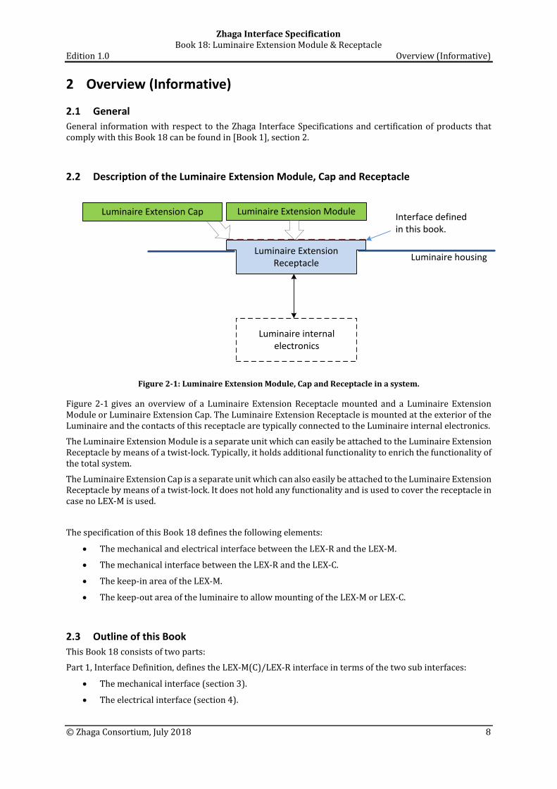
Figure 2-1: Luminaire Extension Module, Cap and Receptacle in a system.
Figure 2-1 gives an overview of a Luminaire Extension Receptacle mounted and a Luminaire Extension Module or Luminaire Extension Cap. The Luminaire Extension Receptacle is mounted at the exterior of the Luminaire and the contacts of this receptacle are typically connected to the Luminaire internal electronics.
The Luminaire Extension Module is a separate unit which can easily be attached to the Luminaire Extension Receptacle by means of a twist-lock. Typically, it holds additional functionality to enrich the functionality of the total system.
The Luminaire Extension Cap is a separate unit which can also easily be attached to the Luminaire Extension Receptacle by means of a twist-lock. It does not hold any functionality and is used to cover the receptacle in case no LEX-M is used.
The specification of this Book 18 defines the following elements:
• The mechanical and electrical interface between the LEX-R and the LEX-M.
• The mechanical interface between the LEX-R and the LEX-C.
• The keep-in area of the LEX-M.
• The keep-out area of the luminaire to allow mounting of the LEX-M or LEX-C.
2.3 Outline of this Book This Book 18 consists of two parts:
Part 1, Interface Definition, defines the LEX-M(C)/LEX-R interface in terms of the two sub interfaces:
• The mechanical interface (section 3).
• The electrical interface (section 4).

Zhaga Interface Specification Book 18: Luminaire Extension Module & Receptacle Edition 1.0 Overview (Informative)
© Zhaga Consortium, July 2018 9
Part 2, Compliance Tests, defines:
• Specific tools, which are used for testing compliance of a LEX-M, a LEX-C or a LEX-R (section 5).
• The Luminaire Extension Module compliance tests (section 6).
• The Luminaire Extension Cap compliance tests (section 7).
• The Luminaire Extension Receptacle compliance tests (section 8).

Zhaga Interface Specification Book 18: Luminaire Extension Module & Receptacle Edition 1.0
© Zhaga Consortium, July 2018 10
Part 1: Interface Definition

Zhaga Interface Specification Book 18: Luminaire Extension Module & Receptacle Edition 1.0 Mechanical interface
© Zhaga Consortium, July 2018 11
3 Mechanical interface The mechanical interface between LEX-R and LEX-M/LEX-C is defined in this section. For the purpose of this section, also the provisions in [Book 1] - section 3.3, apply.
3.1 Drawing principles The characteristics of the mechanical interface are specified according to the following principles:
• The dimensions are in millimeters.
• Third angle projection is used.
3.2 Mechanical references The reference plane, the reference point and the reference axes of LEX-R and LEX-M are defined in Figure 3-1.
Reference point
Reference plane(See mechanical drawing for definition)
X-axis
Y-axis
Z-axis
Receptacle
Module
Top View
X-axis
Y-axis
Z-axis
Figure 3-1: Positions of the reference point, the reference plane and reference axes of the LEX-R and LEX-M.
When the LEX-M is attached to the LEX-R in locking position, the reference point, the reference plane and the reference axes of both products coincide. For applications where the orientation or the LEX-R to the environment of the Luminaire (for example the street) is important, guidelines are provided in Annex A.

Zhaga Interface Specification Book 18: Luminaire Extension Module & Receptacle Edition 1.0 Mechanical interface
© Zhaga Consortium, July 2018 12
3.3 Definition of the mechanical interface of the Luminaire Extension Module The Luminaire Extension Module shall comply with the definition in Figure 3-2, Figure 3-3, Figure 3-4, Figure 3-5, Figure 3-6 and Figure 3-7. Unless indicated otherwise, the tolerance on linear dimensions is ±0.12 mm and the tolerance on angular dimensions is ±1.0⁰.
The outer diameter of the LEX-M shall be less than or equal to 89 mm.
The gasket of the LEX-R should be the only feature imparting the force on the LEX-M to ensure locking.
When mated with a gauge as defined in 5.1.1, the mechanical stop features of the LEX-M (see Figure 3-6) shall withstand a torque of 5 Nm.
Figure 3-2: Mechanical interface of the LEX-M; Mating face-1.
Notes to Figure 3-2:
• X-axis and Y-axis coincide with centerline of locking points as defined in Figure 3-6.

Zhaga Interface Specification Book 18: Luminaire Extension Module & Receptacle Edition 1.0 Mechanical interface
© Zhaga Consortium, July 2018 13
Figure 3-3: Mechanical interface of the LEX-M; Mating face-2.

Zhaga Interface Specification Book 18: Luminaire Extension Module & Receptacle Edition 1.0 Mechanical interface
© Zhaga Consortium, July 2018 14
Figure 3-4: Details of the mechanical interface of the LEX-M: section B-B
Figure 3-5: Details of the mechanical interface of the LEX-M: section E-E

Zhaga Interface Specification Book 18: Luminaire Extension Module & Receptacle Edition 1.0 Mechanical interface
© Zhaga Consortium, July 2018 15
The contact areas of the LEX-M contacts are indicated by ‘Contact Area’ in Figure 3-5. The contact areas of each contacts of the LEX-M shall be completely tin plated on both sides.
Informative: Depending on the design of the contacts in the LEX-R, either or both sides of the LEX-M contacts can be used for contact making.
Figure 3-6: Details of the mechanical interface of the LEX-M: section C-C and section D-D
Figure 3-7: Details of the mechanical interface of the LEX-M: section F-F
The sealing surface shall be free of obstacles that can prevent mating1.
1 Note that the seal has two functions: ingress protection and a spring function to keep the module in locked position.

Zhaga Interface Specification Book 18: Luminaire Extension Module & Receptacle Edition 1.0 Mechanical interface
© Zhaga Consortium, July 2018 16
3.4 Definition of the mechanical interface of the Luminaire Extension Cap The mechanical interface of the Luminaire Extension Cap shall be equal to mechanical interface of the Luminaire Extension Module as defined in section 3.3 except that the Luminaire Extension Cap shall not have contacts.
3.5 Definition of the mechanical interface of the Luminaire Extension Receptacle The Luminaire Extension Receptacle shall comply with the definition in Figure 3-8 and Figure 3-9. Unless indicated otherwise, the tolerance on linear dimensions is ±0.12 mm and the tolerance on angular dimensions is ±1.0⁰.
A LEX-R shall mate with the gauges as defined in sections 5.2.1 and 5.2.2. Moreover, the LEX-R shall have 4 contacts and these contacts shall make electrical contact with the corresponding contacts of the gauges as defined in 5.2.1 and 5.2.2.
The contacts shall be tin plated.
After 5 mating cycles with the gauge defined in section 5.2.3, the torque for un-mating shall be 1.0 Nm or more. During evaluation no downward, axial force shall be applied.
The gasket area as defined in Figure 3-10 shall be free of obstacles that can prevent mating.
The gasket of the LEX-R shall be such that mating and un-mating with a gauge defined in section 5.2.3 is possible with one hand.

Zhaga Interface Specification Book 18: Luminaire Extension Module & Receptacle Edition 1.0 Mechanical interface
© Zhaga Consortium, July 2018 17
Figure 3-8: Mechanical interface of the LEX-R. Details in next figure.
Notes to Figure 3-8:
• X-axis and Y-axis coincide with centerline of locking point as defined in Figure 3-9.

Zhaga Interface Specification Book 18: Luminaire Extension Module & Receptacle Edition 1.0 Mechanical interface
© Zhaga Consortium, July 2018 18
Figure 3-9: Detail of the mechanical interface of the LEX-R
3.6 Definition of the mechanical interface of the Luminaire The gasket area and the Luminaire keep-out area are defined in Figure 3-10.
Within Luminaire keep-out Area, the top surface of the Luminaire should have no features that protrude above a plane 4.6 mm below the reference plane.

Zhaga Interface Specification Book 18: Luminaire Extension Module & Receptacle Edition 1.0 Mechanical interface
© Zhaga Consortium, July 2018 19
Figure 3-10: Gasket area and Keep-out area of the Luminaire

Zhaga Interface Specification Book 18: Luminaire Extension Module & Receptacle Edition 1.0 Electrical interface
© Zhaga Consortium, July 2018 20
4 Electrical interface
4.1 Electrical interface to the Luminaire Extension Module The contacts on the Luminaire Extension Module should be assigned to the functionality as indicated in Table 4-1.
Contact
Module
(Figure 3-2)
Contact
Receptacle
(Figure 3-8)
Assignment
1 1 • +24 V power supply
2 2 • Negative pole for the [DALI] protocol • Ground for +24V power supply (contact 1) • Ground for General Digital IO (contact 4)
3 3 • Positive pole for the [DALI] protocol
4 4 • General Digital I/O (greater than 7V)
Table 4-1: Assignments of contacts in LEX-M and LEX-R.
The LEX-M should have a suitable insulation level for connections to basic and double insulated control interfaces as defined in [IEC60598-1].
4.2 Definition of the electrical interface of the Luminaire Extension Receptacle The contacts on the Luminaire Extension Receptacle should be assigned to the functionality as indicated in Table 4-1.
The LEX-R should have a suitable insulation level for connections to basic and double insulated control interfaces as defined in [IEC60598-1].

Zhaga Interface Specification Book 18: Luminaire Extension Module & Receptacle Edition 1.0
© Zhaga Consortium, July 2018 21
Part 2: Compliance Tests

Zhaga Interface Specification Book 18: Luminaire Extension Module & Receptacle Edition 1.0 Compliance test tools
© Zhaga Consortium, July 2018 22
5 Compliance test tools
5.1 Luminaire Extension Module test tools
5.1.1 Mechanical-stop-gauge The Mechanical-stop-gauge is defined in Annex B. This gauge is used to verify whether the mechanical stop features of the LEX-M under test (see Figure 3-6) can withstand a torque of 5 Nm.
5.2 Luminaire Extension Receptacle test tools
5.2.1 Contact-making-gauge-min The Contact-making-gauge-min is defined in Annex C. This gauge is used to verify whether the LEX-R under test can mate with a LEX-M that is compliant with this specification and whether all contacts of the LEX-R under test make electrical contact with all contacts of a LEX-M that is compliant with this specification
5.2.2 Contact-making-gauge-max The Contact-making-gauge-max is defined in Annex C. This gauge is used to verify whether the LEX-R under test can mate with a LEX-M that is compliant with this specification and whether all contacts of the LEX-R under test make electrical contact with all contacts of a LEX-M that is compliant with this specification
5.2.3 Un-mating-torque-gauge The Un-mating-torque-gauge is defined in Annex D. This gauge is used to verify whether after 5 mating cycles of the LEX-R under test with the gauge the torque for un-mating is 1.0 Nm or more.

Zhaga Interface Specification Book 18: Luminaire Extension Module & Receptacle Edition 1.0 Luminaire Extension Module Compliance Tests
© Zhaga Consortium, July 2018 23
6 Luminaire Extension Module Compliance Tests
6.1 Luminaire Extension Module mechanical interface tests
6.1.1 Test of mechanical dimensions The purpose of this test is to verify the mechanical dimensions of the Luminaire Extension Module under test.
6.1.1.1 Test equipment None
6.1.1.2 Test conditions Not applicable
6.1.1.3 Test procedure
• The manufacturer provides the mechanical drawing of the Luminaire Extension Module under test. This drawing shall include for each dimension listed in Table 6-1, Table 6-2, Table 6-3, Table 6-4, Table 6-5 and Table 6-6 the typical value and the production tolerance.
• Check whether for all dimensions listed in Table 6-1, Table 6-2, Table 6-3, Table 6-4, Table 6-5 and Table 6-6 nominal value and production tolerances are available in the drawing provided by the manufacturer.
• Check whether for all dimensions listed in Table 6-1, Table 6-2, Table 6-3, Table 6-4, Table 6-5 and Table 6-6 the nominal value and production tolerances guarantee products within the tolerance range defined in Table 6-1, Table 6-2, Table 6-3, Table 6-4, Table 6-5 and Table 6-6.
• The manufacturer provides a report of the mechanical measurement of the Luminaire Extension Module under test as described in Annex E.
• Check whether measurement results for all dimensions listed in Table 6-1, Table 6-2, Table 6-3, Table 6-4, Table 6-5 and Table 6-6 are available in the report provided by the manufacturer.
• Check whether for all dimensions listed in Table 6-1, Table 6-2, Table 6-3, Table 6-4, Table 6-5 and Table 6-6 the measured value is within the tolerance range.
Dimension Nom. value
Description
Mod
ule
Cap
Number of occurrences
to check
Tolerance
min max
M01 28.20 Ø indent √ √ 1 -0.18 +0.12
M02 12.0 Ø contact √ 1 -0.12 +0.12
- Eccentricity contact √ 1 - Ø0.15
M03 47⁰ Contact angle √ 4 -1.0⁰ +1.0⁰
M04 0.80 Thickness of contacts √ 4 -0.05 +0.05
M05 90.0⁰ Relative Contact position √ 4 -1.0⁰ +1.0⁰
M07 7.8⁰ Contact position relative to edge of indent
√ 1 -1.0⁰ +1.0⁰
Table 6-1: Dimension of the LEX-M and LEX-C defined in Figure 3-2.

Zhaga Interface Specification Book 18: Luminaire Extension Module & Receptacle Edition 1.0 Luminaire Extension Module Compliance Tests
© Zhaga Consortium, July 2018 24
Dimension Nom. value
Description
Mod
ule
Cap
Number of occurrences
to check
Tolerance
min Max
M08 - Ø center cut-out √ √ 1 8.50 -
- Eccentricity cut-out √ √ 1 - Ø0.15
M09 30.40 Ø cavity √ √ 1 -0.12 +0.12
- Max. material eccentricity cavity √ √ 1 - Ø0.10
M10 - Ø sealing keep-out area √ √ 1 38.50 -
M11 - Ø center post √ √ 1 - 4.90
- Eccentricity contact √ √ 1 - Ø0.15
M12 135⁰ Position of indent (1) √ √ 1 -1.0⁰ +1.0⁰
M13 90⁰ Position of indent (2) √ √ 1 -1.0⁰ +1.0⁰
M14 16.8⁰ Width of indent √ √ 2 -1.0⁰ +1.0⁰
M15 25.3⁰ Width of indent √ √ 1 -1.0⁰ +1.0⁰
Table 6-2: Dimension of the LEX-M and LEX-C defined in Figure 3-3.
Dimension Nom. value
Description
Mod
ule
Cap
Number of occurrences
to check
Tolerance
min Max
M16 - Length of center post √ √ 1 - 4.30
M17 - Distance to Ref. plane √ √ 1 4.10 -
M18 - Distance to Ref. plane √ √ 1 5.50 -
Table 6-3: Dimension of the LEX-M and LEX-C defined in Figure 3-4.

Zhaga Interface Specification Book 18: Luminaire Extension Module & Receptacle Edition 1.0 Luminaire Extension Module Compliance Tests
© Zhaga Consortium, July 2018 25
Dimension Nom. value
Description
Mod
ule
Cap
Number of occurrences
to check
Tolerance
min Max
M19 - Blade stand width √ 4 - 3.20
M20 3.50 Height of blade √ 4 -0.12 +0.12
M21 2.70 Bottom of blade to Ref. plane √ 4 -0.12 +0.12
Table 6-4: Dimension of the LEX-M and LEX-C defined in Figure 3-5.
Dimension Nom. value
Description
Mod
ule
Cap
Number of occurrences
to check
Tolerance
min Max
M22 0.80 Radius of locking feature √ √ 3 -0.10 +0.10
M23 1.00 Distance to Ref. plane √ √ 3 -0.12 +0.12
Table 6-5: Dimension of the LEX-M and LEX-C defined in Figure 3-6.
Dimension Nom. value
Description
Mod
ule
Cap
Number of occurrences
to check
Tolerance
min Max
M24 10⁰ Ramp of sealing surface √ √ 1 -1.0⁰ +1.0⁰
M25 3.75 Bottom of sealing surface to Ref. plane √ √ 3 -0.12 +0.12
M26 0.62 Height of ramp √ √ 1 -0.12 +0.12
Table 6-6: Dimension of the LEX-M and LEX-C defined in Figure 3-7.
6.1.1.4 Pass criteria The Luminaire Extension Module under test passes if for all dimensions listed in Table 6-1, Table 6-2, Table 6-3, Table 6-4, Table 6-5 and Table 6-6 holds:
• The mechanical drawing shows compliance with the requirements in section 3.3 within the specified tolerance and
• The measurement report shows compliance with the requirements in section 3.3 within the specified tolerance.
6.1.2 Test of LEX-M outer diameter The purpose of this test is to verify whether the Luminaire Extension Module under test is within the limit as defined in section 3.3.

Zhaga Interface Specification Book 18: Luminaire Extension Module & Receptacle Edition 1.0 Luminaire Extension Module Compliance Tests
© Zhaga Consortium, July 2018 26
6.1.2.1 Test equipment Caliper
6.1.2.2 Test conditions This test shall be conducted at 25 ± 5 ℃.
6.1.2.3 Test procedure • Measure the outer diameter of the LEX-M under test. In case the outer geometry is not circular, the
maximum diameter shall be used in this test.
6.1.2.4 Pass criteria The Luminaire Extension Module under test passes if the outer diameter of the LEX-M under test is within the limit as defined in section 3.3.
6.1.3 Test of the LEX-M mechanical stop features The purpose of this test is to verify whether mechanical stop features of the LEX-M (see Figure 3-6) can withstand a torque of 5 Nm.
6.1.3.1 Test equipment • Mechanical-stop-gauge as defined in 5.1.1.
• Torque meter
6.1.3.2 Test conditions This test shall be conducted at 25 ± 5 ℃.
6.1.3.3 Test procedure • Attach the LEX-M under test to the mechanical-stop-gauge
• Apply for 1 minute a torque of 5 Nm to attach the LEX-M with no axial force.
• Apply for 1 minute a torque of 5 Nm to detach the LEX-M with no axial force.
6.1.3.4 Pass criteria The Luminaire Extension Module under test passes if the function of mechanical stop is not impaired after the test.
6.1.4 Test of the LEX-M sealing surface The purpose of this test is to verify whether the sealing surface of the LEX-M under test is be free of obstacles that can prevent mating.
6.1.4.1 Test equipment None
6.1.4.2 Test conditions None
6.1.4.3 Test procedure • Inspect visually the sealing surface of the LEX-M under test and check whether it is free of obstacles
that can prevent mating.

Zhaga Interface Specification Book 18: Luminaire Extension Module & Receptacle Edition 1.0 Luminaire Extension Module Compliance Tests
© Zhaga Consortium, July 2018 27
6.1.4.4 Pass criteria The Luminaire Extension Module under test passes if the sealing surface of the LEX-M under test is free of obstacles that can prevent mating.
6.1.5 Test of the LEX-M contact plating The purpose of this test is to confirm that the plating to the contact areas of the LEX-M contains the minimum proportion of tin required by this specification.
6.1.5.1 Test equipment X-ray Fluorescence measurement device with a measurement accuracy of ±5% at the 95% confidence level.
6.1.5.2 Test conditions None.
6.1.5.3 Test procedure • Define ad random a measurement point in the contact area on either sides of one of the 4 contacts
of the LEX-M.
• Measure the compostion of the contact plating with a X-ray Fluorescence measurement device. The percentage mass of all elements present shall be recorded.
6.1.5.4 Pass criteria The Luminaire Extension Module under test passes if the composition of the contact plating at the measurement point complies with the restrictions in Table 6-7.
Element % mass
Tin ≥97.5
Copper ≤1.5
Zinc ≤0.7
Total Unnamed Elements ≤0.2
Lead ≤0.1
Table 6-7: Pass criteria for percentage mass of several elements in the contact plating.

Zhaga Interface Specification Book 18: Luminaire Extension Module & Receptacle Edition 1.0 Luminaire Extension Cap Compliance Tests
© Zhaga Consortium, July 2018 28
7 Luminaire Extension Cap Compliance Tests
7.1 Luminaire Extension Cap mechanical interface tests
7.1.1 Test of mechanical dimensions See section 6.1.1. Only the dimensions with a flag in the column “CAP” in Table 6-1 to Table 6-6 need to be verified.
7.1.2 Test of LEX-M outer diameter See section 6.1.2.
7.1.3 Test of the LEX-M mechanical stop features See section 6.1.3.
7.1.4 Test of the LEX-M sealing surface See section 6.1.4.

Zhaga Interface Specification Book 18: Luminaire Extension Module & Receptacle Edition 1.0 Luminaire Extension Receptacle compliance tests
© Zhaga Consortium, July 2018 29
8 Luminaire Extension Receptacle compliance tests
8.1 Luminaire Extension Receptacle mechanical interface tests
8.1.1 Test of mechanical dimensions The purpose of this test is to verify the mechanical dimensions of the Luminaire Extension Receptacle under test.
8.1.1.1 Test equipment None
8.1.1.2 Test conditions Not applicable
8.1.1.3 Test procedure
• The manufacturer provides the mechanical drawing of the Luminaire Extension Receptacle under test. This drawing shall include for each dimension listed in Table 6-1, Table 6-2, Table 6-3, Table 6-4, Table 6-5 and Table 6-6 the typical value and the production tolerance.
• Check whether for all dimensions listed in Table 8-1 and Table 8-2 nominal value and production tolerances are available in the drawing provided by the manufacturer.
• Check whether for all dimensions listed in Table 8-1 and Table 8-2 the nominal value and production tolerances guarantee products within the tolerance range defined in Table 8-1 and Table 8-2.
• The manufacturer provides a report of the mechanical measurement of the Luminaire Extension Receptacle under test as described in Annex E.
• Check whether measurement results for all dimensions listed in Table 8-1 and Table 8-2 are available in the report provided by the manufacturer.
• Check whether for all dimensions listed in Table 8-1 and Table 8-2 the measured value is within the tolerance range.

Zhaga Interface Specification Book 18: Luminaire Extension Module & Receptacle Edition 1.0 Luminaire Extension Receptacle compliance tests
© Zhaga Consortium, July 2018 30
Dimension Nom. value
Description Number of occurrences
to check
Tolerance
min max
R01 - Ø hole for center post 1 5.35 -
- Eccentricity hole for pole 1 - Ø0.15
R02 30.0 Ø outline 1 -0.12 +0.12
Max. material eccentricity outline 1 - Ø0.10
R03 28.0 Ø indent 1 -0.20 +0.00
R04 - Width of center ring 1 - 8.12
- Eccentricity of center ring 1 - Ø0.15
R05 - Height of top surface 1 - 3.35
R06 - Height of center ring 1 - 4.60
R07 - Depth of center hole 1 9.75 -
Table 8-1: Dimension of the LEX-M and LEX-C defined in Figure 3-8.
Dimension Nom. value
Description Number of occurrences
to check
Tolerance
min max
R08 3.76 Locking point to edge 3 -0.12 +0.12
R09 0.90 Curvature of locking point 3 -0.10 +0.10
R10 - Mechanical stop 1 2.00 -
R11 0.60 Lock bump 3 -0.12 +0.12
R12 - Position locking point 3 1.20 -
Table 8-2: Dimension of the LEX-M and LEX-C defined in Figure 3-9.
8.1.1.4 Pass criteria
The Luminaire Extension Receptacle under test passes if for all dimensions listed in Table 8-1 and Table 8-2 holds:
• The mechanical drawing shows compliance with the requirements in section 3.5 within the specified tolerance and
• The measurement report shows compliance with the requirements in section 3.5 within the specified tolerance.

Zhaga Interface Specification Book 18: Luminaire Extension Module & Receptacle Edition 1.0 Luminaire Extension Receptacle compliance tests
© Zhaga Consortium, July 2018 31
8.1.2 Test of the LEX-R mating & contact making The purpose of this test is to verify whether the A LEX-R can mate with a LEX-M that is compliant with this specification and all contacts of a LEX-R make electrical contact with all contacts of a LEX-M that is compliant with this specification.
8.1.2.1 Test equipment
• Contact-making-gauge-min as defined in 5.2.1. • Contact-making-gauge-max as defined in 5.2.2. • Ohms meter or contact making tester.
8.1.2.2 Test conditions This test shall be conducted at 25 ± 5 ℃.
8.1.2.3 Test procedure • Mount the LEX-R, including gasket according to the manufacturer’s instruction on a flat plate.
• Attach the contact-making-gauge-min to the LEX-R under test. Check whether the gauge fits the LEX-R under test without undue force and whether all 4 electrical connections are established.
• Attach the contact-making-gauge-max to the LEX-R under test. Check whether the gauge fits the LEX-R under test without undue force and whether all 4 electrical connections are established.
8.1.2.4 Pass criteria The Luminaire Extension Receptacle under test passes if the test result confirms that both gauges fit the LEX-R under test and with both gauges, all 4 electrical connections are established.
8.1.3 Test of the LEX-R mating and un-mating torque The first purpose of this test is to verify whether after 5 mating cycles with the gauge defined in section 5.2.3, the torque for un-mating is 1.0 Nm or more.
The second purpose of this test if the gasket of the LEX-R is such that mating and un-mating with a gauge defined in section 5.2.3 is possible with one hand.
The third purpose of the test is to verify that the gasket area as defined in Figure 3-10 is free of obstacles that can prevent mating.
8.1.3.1 Test equipment
• Un-mating-torque-gauge as defined in 5.2.3. • Torque meter.
8.1.3.2 Test conditions This test shall be conducted at 25 ± 5 ℃.
8.1.3.3 Test procedure • Mount the LEX-R, including gasket according to the manufacturer’s instruction on a flat plate.
• Perform 5 mating sequences with the un-mating-torque-gauge and the LEX-R under test. The test shall be performed with one hand and no axial force shall be applied.
• Measure the torque required to detach the un-mating-torque-gauge from the LEX-R under test. During this measurement no axial force shall be applied.
8.1.3.4 Pass criteria The Luminaire Extension Receptacle under test passes if it can be performed with one hand and the measured torque is 1.0 Nm or more.

Zhaga Interface Specification Book 18: Luminaire Extension Module & Receptacle Edition 1.0 Luminaire Extension Receptacle compliance tests
© Zhaga Consortium, July 2018 32
8.1.4 Test of the LEX-R contact plating The purpose of this test is to confirm that the plating to the contact areas of the LEX-R contains the minimum proportion of tin required by this specification.
8.1.4.1 Test equipment X-ray Fluorescence measurement device with a measurement accuracy of ±5% at the 95% confidence level.
8.1.4.2 Test conditions None.
8.1.4.3 Test procedure
• The LEX-R manufacturers provides a statement to the ATC indicating the contact area of the contacts.
• Define ad random a measurement point in the contact area on either sides of one of the 4 contacts of the LEX-R.
• Measure the compostion of the contact plating with a X-ray Fluorescence measurement device. The percentage mass of all elements present shall be recorded.
8.1.4.4 Pass criteria The Luminaire Extension Receptacle under test passes if the composition of the contact plating at the measurement point complies with the restrictions in Table 6-7.
Element % mass
Tin ≥97.5
Copper ≤1.5
Zinc ≤0.7
Total Unnamed Elements ≤0.2
Lead ≤0.1
Table 8-3: Pass criteria for percentage mass of several elements in the contact plating.

Zhaga Interface Specification Book 18: Luminaire Extension Module & Receptacle Edition 1.0 Application guidelines
© Zhaga Consortium, July 2018 33
Annex A Application guidelines The Luminaire Extension Receptacles and the Luminaire Extension Modules are intended to be used in outdoor applications. In some of these applications, the orientation of the LEX-M with respect to its environment is essential for proper functioning. For applications where this is the case, it is important that the orientation is correct also after attaching a new the LEX-M, possibly from another brand. In order to facilitate this, the recommended orientations are defined for several applications.
It is also recommended that information on the orientation and mounting of the LEX-M and LEX-R is available in the product documentation.
A.1 Street lighting For this application it is recommended that the Luminaire and the LEX-R in the Luminaire are mounted such that the Y-axis of the receptacle is perpendicular to the road and is pointing towards the center of the road. See Figure A-1.
Also for this application it is recommended that the LEX-M is constructed assuming that the Luminaire and the LEX-R in the luminaire are mounted such that the Y-axis of the receptacle is perpendicular to the road and is pointing towards the center of the road.
X-axis
Y-axis
Z-axisX-axis
Y-axis
Z-axis
LEX-R and LEX-M mounted on top of luminaire
LEX-R and LEX-M mounted at bottom of luminaire
Figure A-1: Orientation for LEX-R and LEX-M in street lighting applications.

Zhaga Interface Specification Book 18: Luminaire Extension Module & Receptacle Edition 1.0 Mechanical drawing of the Mechanical-stop-gauge
© Zhaga Consortium, July 2018 34
Annex B Mechanical drawing of the Mechanical-stop-gauge

Zhaga Interface Specification Book 18: Luminaire Extension Module & Receptacle Edition 1.0 Mech. drawing of the Contact-making-gauge-min and Contact-making-gauge-max
© Zhaga Consortium, July 2018 35
Annex C Mech. drawing of the Contact-making-gauge-min and Contact-making-gauge-max

Zhaga Interface Specification Book 18: Luminaire Extension Module & Receptacle Edition 1.0 Mechanical drawing of the Un-mating-torque-gauge
© Zhaga Consortium, July 2018 36
Annex D Mechanical drawing of the Un-mating-torque-gauge

Zhaga Interface Specification Book 18: Luminaire Extension Module & Receptacle Edition 1.0 LEX-M and LEX-R mechanical interface tests (Informative)
© Zhaga Consortium, July 2018 37
Annex E LEX-M and LEX-R mechanical interface tests (Informative)
E.1 LEX-M mechanical interface tests
8.1.5 Test of mechanical dimensions The purpose of this test is to verify the mechanical dimensions of the Luminaire Extension Module under test.
8.1.5.1 Test equipment This test should be conducted with measuring equipment allowing a measurement accuracy (linear and angular) equal or better than 0.2 x tolerance. This test may be conducted by optical or tactile measurement techniques but in this case the LEX-M under test will need to be sectioned in order to measure certain dimension. Alternatively, topographic techniques may be used.
8.1.5.2 Test conditions This test shall be conducted at 25 ± 5 ℃.
8.1.5.3 Test procedure • Measure all dimensions listed in Table 6-1, Table 6-2, Table 6-3, Table 6-4, Table 6-5 and Table 6-6.
E.2 LEX-R mechanical interface tests
8.1.6 Test of mechanical dimensions The purpose of this test is to verify the mechanical dimensions of the Luminaire Extension Module under test.
8.1.6.1 Test equipment This test should be conducted with measuring equipment allowing a measurement accuracy (linear and angular) equal or better than 0.2 x tolerance. This test may be conducted by optical or tactile measurement techniques but in this case the LEX-M under test will need to be sectioned in order to measure certain dimension. Alternatively, topographic techniques may be used.
8.1.6.2 Test conditions This test shall be conducted at 25 ± 5 ℃.
8.1.6.3 Test procedure • Measure all dimensions listed in Table 8-1 and Table 8-2.