bone as a composite material: the role of osteons as barriers to
TRANSCRIPT
Royal College of Surgeons in Irelande-publications@RCSI
Anatomy Articles Department of Anatomy
1-6-2007
Bone as a composite material: the role of osteons asbarriers to crack growth in compact bone.Fergal J. O'BrienRoyal College of Surgeons in Ireland, [email protected]
David TaylorTrinity College Dublin
T Clive LeeRoyal College of Surgeons in Ireland
This Article is brought to you for free and open access by the Departmentof Anatomy at e-publications@RCSI. It has been accepted for inclusion inAnatomy Articles by an authorized administrator of [email protected] more information, please contact [email protected].
CitationO'Brien, F.J.; Taylor, D. and Lee, T.C. Bone as a composite material: the role of osteons as barriers to crack growth in compact bone.International Journal of Fatigue 2007 (29): 1051-1056.
— Use Licence —
Attribution-Non-Commercial-ShareAlike 1.0You are free:• to copy, distribute, display, and perform the work.• to make derivative works.Under the following conditions:• Attribution — You must give the original author credit.• Non-Commercial — You may not use this work for commercial purposes.• Share Alike — If you alter, transform, or build upon this work, you may distribute the resulting work onlyunder a licence identical to this one.For any reuse or distribution, you must make clear to others the licence terms of this work. Any of theseconditions can be waived if you get permission from the author.Your fair use and other rights are in no way affected by the above.This work is licenced under the Creative Commons Attribution-Non-Commercial-ShareAlike License. Toview a copy of this licence, visit:URL (human-readable summary):• http://creativecommons.org/licenses/by-nc-sa/1.0/URL (legal code):• http://creativecommons.org/worldwide/uk/translated-license
This article is available at e-publications@RCSI: http://epubs.rcsi.ie/anatart/6
Bone as a composite material:
the role of osteons as barriers to crack growth in compact bone
Fergal J. O’Brien a,b*, David Taylor b , T. Clive Lee a,b
aDepartment of Anatomy, Royal College of Surgeons in Ireland,
St Stephen’s Green, Dublin 2, Ireland
bTrinity Centre for Bioengineering, School of Engineering,
Trinity College, Dublin, Ireland
Abbreviated title: The role of osteons as microstructural barriers in compact bone
Keywords: fatigue, bone, microcrack, propagation
* Corresponding author. Tel: +353-1-402-2149; Fax: +353-1-402-2355.
E-mail address: [email protected]
ABSTRACT
This article summarises a number of studies in the area of bone microdamage which
were carried out in our laboratory over the past 5 years. A technique was developed to
label microcracks during mechanical testing. Fluorescent chelating agents were
applied at intervals to bone specimens fatigue tested in cyclic compression until
failure occurred. Microcrack densities were measured and microcrack length at the
time of encountering the cement line surrounding an osteon was also recorded.
Microcracks were shown to develop rapidly during the first stage of testing but then
further accumulation of cracks did not occur until the period just before failure. The
majority of microcracks were found in interstitial bone and did not penetrate cement
lines. Only microcracks greater than 300µm in length were found to be capable of
penetrating osteons. This work provides experimental data to support the hypothesis
that secondary osteons act as barriers to crack propagation in compact bone.
1 INTRODUCTION
Fatigue damage in bone occurs in the form of microcracks due to the regular day to
day activities of normal life in healthy human beings. This damage acts as a stimulus
for bone remodelling (Martin and Burr [1], Burr et al. [2], Burr and Martin [3], Mori
and Burr [4], Lee et al. [5], Martin [6], O’Brien et al. [7]). Bones, therefore, have an
advantage over most engineering structures in that they have an inherent ability to
repair damage. However if this damage accumulates at such a rate that the capacity
for bone repair is exceeded, stress fractures result. These fractures occur commonly
in athletes and soldiers engaged in high intensity, repetitive activities such as
marching or running. If, on the other hand, damage accumulates at 'normal' rates but
the bone’s repair mechanism is deficient, fragility fractures result which occur
commonly in osteoporotic bone (Diab et al. [8]; O’Brien et al. [9], Schaffler et al.
[10]).
Secondary osteonal bone has been compared to a composite material and to metals
whereby microstructural features within the material, such as laminae and voids, may
provide sites for crack initiation, but they also serve as barriers to crack growth which
may slow down or even halt crack propagation completely. It has been proposed that
a microstructural barrier concept may exist in bone (Martin and Burr [11], Taylor and
Prendergast [12], Akkus and Rimnac [13]; Sobelman et al. [14]) whereby the
microstructure of osteonal bone provides barriers to crack growth in the form of
cement lines which surround secondary osteons. The cement line interface between
osteons and interstitial bone is relatively weak which means that it may reduce the
shear strength of osteonal bone (Frasca [15]). However it has been hypothesised that
slipping at this interface relaxes shear stresses, reducing strain energy and thus
slowing crack propagation. Jepsen et al [16] showed that the lamellar interface in
bone is weak and is the principal site of shear damage formation but the lamellar
interface was shown to be highly effective in keeping cracks isolated from each other.
Zioupos et al. [17] showed that microcracks in bone did interact with the
microstructure of the bone and that the grain of the bone constrained their growth
directions. They hypothesised that the presence of lamellae influenced the process by
which microcracks coalesced but that vascular or other naturally occurring cavities
did not initiate microcracking and appeared to deflect microcracks. Work by
Schaffler et al. [10] added quantitative data to this hypothesis suggesting that 80-90%
of all microcracks in cortical bone are found in the interstitial matrix between osteons.
This article summarises a number of studies which were carried out in our laboratory
over the past four years (O’Brien et al. [18-20]. One of the challenges with studying
microcracks in bone is developing a technique with which to monitor them. Lee et al,
[21] demonstrated that the application of fluorescent chelating agents in sequence
could be used to monitor microcrack growth in vitro. These agents are as effective as
the standard method, basic fuchsin, in identifying microcracks but are also site
specific as they bind to calcium ions lining the crack walls. Each agent fluoresces a
different colour under UV light and so individual agents can be distinguished when
viewed using UV epifluorescence microscopy. However substitution of one agent by
another due to varying affinities for exposed calcium which line the walls of
microcracks made measuring crack growth imprecise. This paper summarises how
the method of detection was refined in order to determine the optimal sequence of
application for five chelating agents which allowed all the agents to fluoresce equally
brightly using UV epifluorescence and avoided substitution. Following development
of the optimal labelling technique, it was proposed to label microcracks and monitor
microcrack development during fatigue testing to look at the process by which
microcracks propagate and interact with the bone’s microstructure ultimately bringing
about failure. Furthermore, the authors sought to test the hypothesis that bone
behaves as a composite material and, if so, to determine the components of the bone’s
microstructure which allow this comparison to be made. In particular, we wished to
determine whether cement lines influenced crack growth and whether a
microstructural barrier phenomenon exists in bone.
2 MATERIALS AND METHODS
2.1 Development of an optimised labelling technique
The aims of this experiment were to refine the method of detection developed by Lee
et al. [21] in order to determine the optimal sequence of application for the five
fluorescent chelating agents which allowed all the agents to fluoresce equally brightly
using UV epifluorescence and avoided substitution. The levels of free calcium in a
solution of calcium chloride before and after the introduction of each chelating agent
were measured using ion chromatography (Haddad and Jackson, [22]). The calcium
chloride concentration was 1 x 10⁻³
M and each of the five chelating agents, alizarin
complexone (A), calcein blue (B), xylenol orange (X) (all from Aldrich Chemical Co.,
Milwaukee, Wi., USA), calcein (C) (Sigma Chemical Co., St. Louis, Mo., USA) and
oxytetracycline (O) (Bimeda Ltd, Dublin) was injected separately at a concentration
of 5 x 10⁻⁴
M. The chelating agents were ranked in order of decreasing affinity for
calcium and this sequence was then tested on bone specimens using a scratch test
technique. Samples of cortical bone were removed from the mid-diaphysis of bovine
tibiae and machined into beam-shaped specimens using a band saw. These were then
finely polished using emery paper. Using a compass point, a 5mm straight line was
scratched on the upper surface of the bone beams. Each specimen was immersed in a
vial containing a 5 x 10⁻⁴
M aqueous solution of the fluorescent agent and placed in a
vacuum desiccator for 4 hours. The specimen was washed in de-ionised water, a
second 5mm line scratched parallel to the first and the specimen immersed in a vial
containing a 5 x 10⁻⁴
M aqueous solution of a second fluorescent agent and placed in
the vacuum desiccator for 4 hours. This protocol was repeated using two, three and
four dye sequences. Following establishment of the optimal sequence of application,
mechanical tests were carried with the fluorochromes applied in sequence to monitor
crack growth.
2.2 Mechanical testing
Samples were taken from fresh bovine tibiae and machined into typical, waisted,
"dog-bone" type specimens of circular cross section using an established protocol
(Taylor et al [23]). Compressive fatigue tests were carried out in an INSTRON 8501
servo-hydraulic testing machine used in load control to apply an axial force to the
specimens, which were enclosed in a small plastic bath to which the dyes could be
added and removed. All tests were carried out at room temperature, at a frequency of
3 Hz, and at a stress range of 80 MPa (between 8 and 88MPa). The fluorescent
chelating agents were applied in the pre-determined sequence in order to label
microcracks formed prior to, and during the tests. Initially, the machined specimens
were placed in a single vial of the first agent in a dessiccator under vacuum for 16
hours to label any microdamage which existed prior to testing. Testing was carried
out with the second agent for the first 10,000 cycles of testing. The test was stopped,
the bath was rinsed with distilled water and the third agent added. Testing was
continued until 50,000 cycles had elapsed and the fourth agent applied. As explained
in the Results and Discussion sections of this paper, difficulties were encountered
with the use of all five agents in sequence and therefore only four agents were used.
Failure was defined using established criteria [23]; a 10% reduction in stiffness which
generally coincided with the appearance of a large crack.
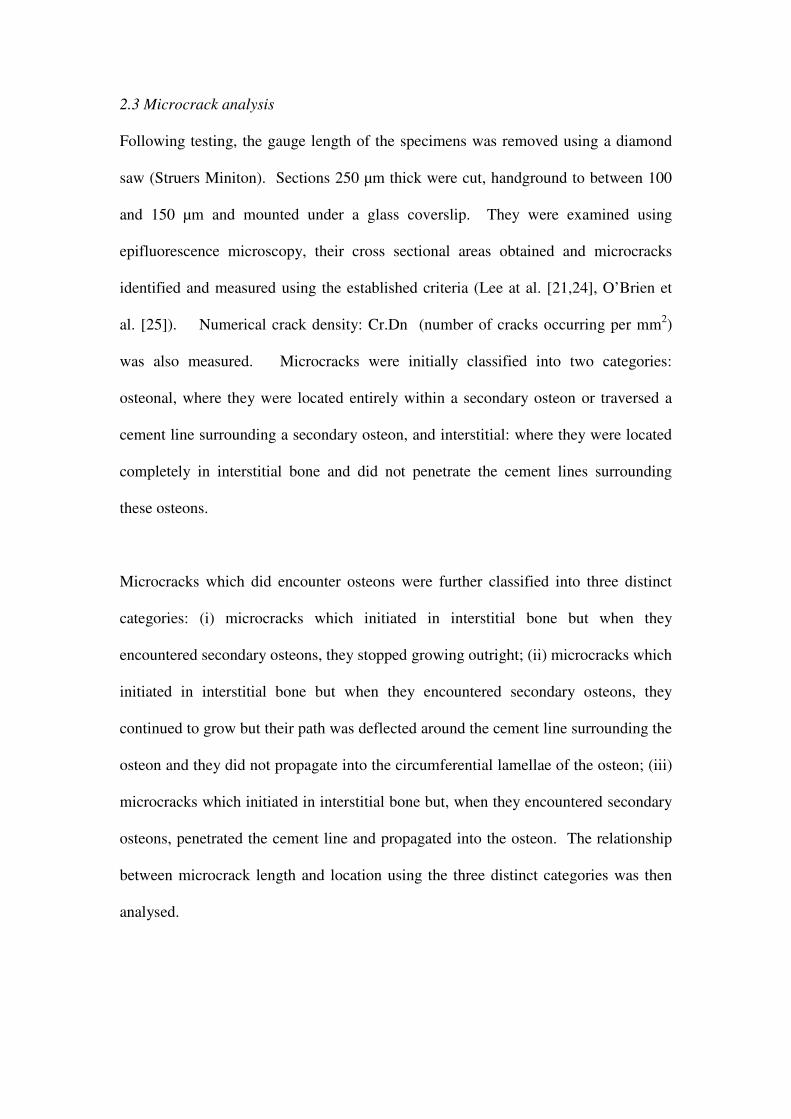
2.3 Microcrack analysis
Following testing, the gauge length of the specimens was removed using a diamond
saw (Struers Miniton). Sections 250 µm thick were cut, handground to between 100
and 150 µm and mounted under a glass coverslip. They were examined using
epifluorescence microscopy, their cross sectional areas obtained and microcracks
identified and measured using the established criteria (Lee at al. [21,24], O’Brien et
al. [25]). Numerical crack density: Cr.Dn (number of cracks occurring per mm2)
was also measured. Microcracks were initially classified into two categories:
osteonal, where they were located entirely within a secondary osteon or traversed a
cement line surrounding a secondary osteon, and interstitial: where they were located
completely in interstitial bone and did not penetrate the cement lines surrounding
these osteons.
Microcracks which did encounter osteons were further classified into three distinct
categories: (i) microcracks which initiated in interstitial bone but when they
encountered secondary osteons, they stopped growing outright; (ii) microcracks which
initiated in interstitial bone but when they encountered secondary osteons, they
continued to grow but their path was deflected around the cement line surrounding the
osteon and they did not propagate into the circumferential lamellae of the osteon; (iii)
microcracks which initiated in interstitial bone but, when they encountered secondary
osteons, penetrated the cement line and propagated into the osteon. The relationship
between microcrack length and location using the three distinct categories was then
analysed.
3 RESULTS
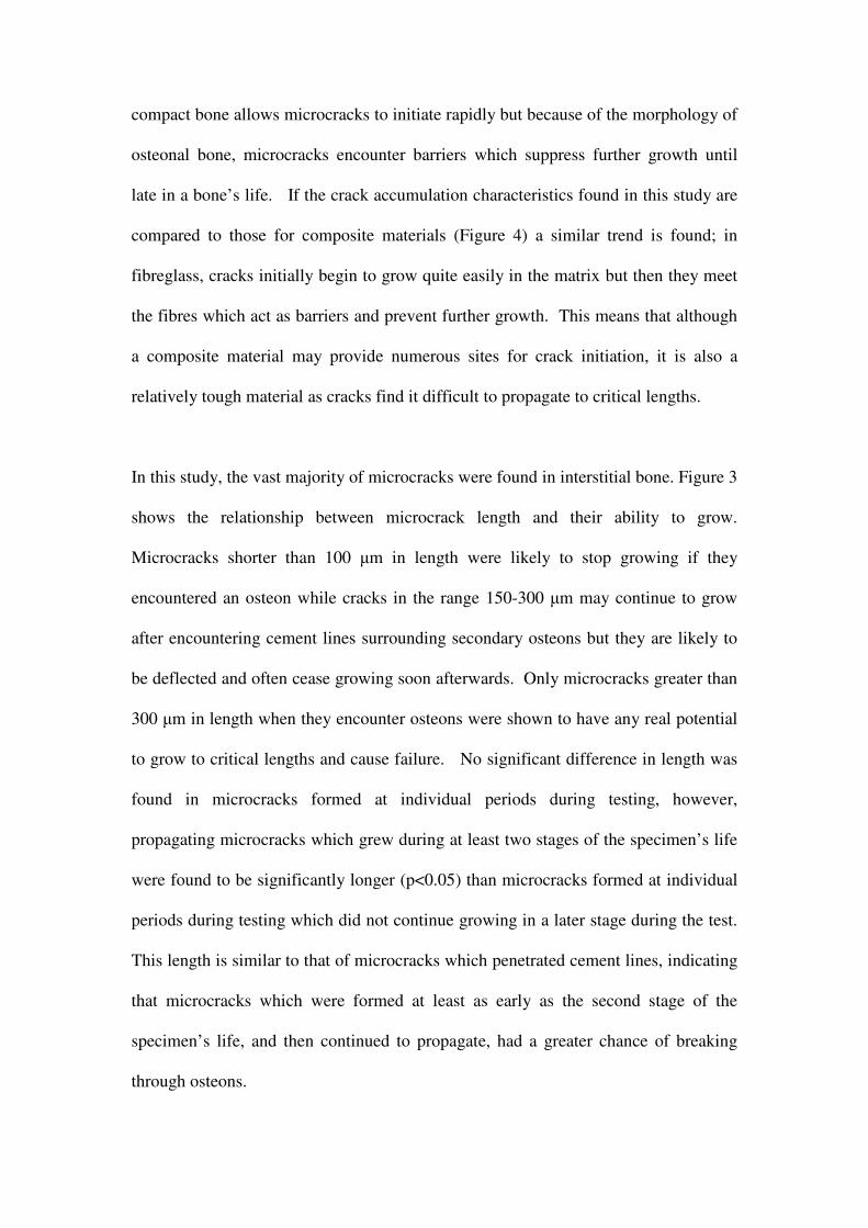
The results from the ion chromatography analysis demonstrated that alizarin
complexone had the greatest affinity for calcium followed by xylenol orange (X),
calcein blue (B), calcein (C) and oxytetracycline (O). Scratch tests were carried out
using chelating agents applied in this order. However the scratch test analysis led to a
revision in this sequence as C was found to have a greater affinity for calcium than B
i.e B followed by C resulted in greater fluorochrome substitution than C followed by
B. The concentration of B was then reduced in stages, firstly to 2.5 x 10⁻⁴
M and then
to 1 x 10⁻⁴
M until the degree of substitution was negligible. O was problematic as it
tended to substitute each of the other agents regardless of the sequence of application.
This could not be rectified by altering the sequence or concentration and so O was
excluded from the study. The revised four stain protocol was A-X-C-B, using 5 x 10⁻⁴
M concentrations of A, X and C and B at 1 x 10⁻⁴
M. Figure 1 demonstrates this
sequence using an image from the scratch test analysis. All four scratched regions
can be clearly distinguished from each other and from the surrounding bone matrix
and substitution is negligible. This sequence was then used during mechanical
testing.
The fluorescent chelating agents allowed a clear distinction to be made between pre-
existing microcracks and microcracks formed at individual periods during testing.
Only 6% of microcracks were pre-existing and these did not propagate during testing.
Figure 2 illustrates the pattern of microcrack accumulation (crack density) during the
course of a test. Microcracks were shown to develop rapidly during the first 10,000
cycles, but no significant increase took place between 10,000 cycles and 50,000
cycles. A further increase in microcrack- density then took place between 50,000
cycles and failure with the mean Nf being 88,380 (S.D. 22,400) cycles to failure. No
significant difference was found in length between microcracks which were found
exclusively in a single period during testing and which did not propagate beyond this
period (0-10,000 cycles, 10,000- 50,000 cycles, 50,000 cycles to failure). The mean
crack length of cracks formed during these periods was found to be 170 µm (S.D. 56
µm). Pre-existing microcracks were short in comparison to the other types (56 µm
S.D. 50 µm), were found close to the surface of the specimen and were not found to
propagate during testing. One of benefits to using this sequential labelling technique
is that microcracks which had propagated between two or more distinct periods of
testing were labelled with two or more dyes and therefore allowed them to be
distinguished from cracks which had been formed during a single period of the test.
These propagating microcracks were found to be longer than microcracks formed at
individual periods during testing (281 µm S.D. 119 µm).
The majority of microcracks were located in interstitial bone (85%) and did not
penetrate the cement lines surrounding secondary osteons. Figure 3 shows the
analysis of those cracks which did encounter cement lines. One-way analysis of
variance (ANOVA) showed that there was a significant difference between all groups
(p<0.05), indicating that crack length at the time of encountering an osteon
significantly affected its ability to propagate. This illustrates the influence of crack
length on its ability to penetrate cement lines and propagate through an osteon. The
first category indicates that if cracks were less than 100 µm (mean: 95 µm S.D. 26
µm) when they encountered a cement line surrounding an osteon, they stopped
growing outright. However the mean length for cracks which were deflected when
they encountered the cement line was 174 µm (S.D. 47 µm). A general observation,
albeit one for which we have no data, showed that these deflected cracks generally
stopped growing soon after the encounter with a cement line and were not observed to
become macroscale cracks. The third category shows cracks which did actually
manage to penetrate one or more osteons; these were significantly longer (p<0.05)
than the other categories (mean: 313 µm S.D. 116 µm).
4. DISCUSSION
This study describes how a technique, using fluorescent chelating agents to
sequentially label microcrack growth in bone was developed (Lee et al. [21]) then
refined (O’Brien et al. [18]) and subsequently used, by applying the agents at different
intervals during a mechanical fatigue test, to learn more about microcracks, their
effect on the fatigue behaviour of bone, their interaction with the bone’s
microstructure and the processes by which they initiate and grow (O’Brien et al.
[19,20]). The optimal sequence of application and concentration of each agent was
alizarin complexone (0.0005M) followed by xylenol orange (0.0005M), calcein
(0.0005M) and calcein blue (0.0001M). A fifth agent, oxytetracycline was excluded
from the study after recurring problems were found with its ability to chelate exposed
calcium when applied in sequence with the other agents. Crack accumulation during
the life of a test specimen followed a characteristic curve in which many cracks
initiate early during the specimen’s life (first 10,000 cycles) but then accumulation of
more cracks is suppressed with only a slight increase occurring between 10,000 and
50,000 cycles before microcracks rapidly accumulate after 50,000 cycles eventually
resulting in failure. It has been proposed that a microstructural barrier concept
governs the fatigue behaviour of bone whereby the microstructure of secondary
compact bone allows microcracks to initiate rapidly but because of the morphology of
osteonal bone, microcracks encounter barriers which suppress further growth until
late in a bone’s life. If the crack accumulation characteristics found in this study are
compared to those for composite materials (Figure 4) a similar trend is found; in
fibreglass, cracks initially begin to grow quite easily in the matrix but then they meet
the fibres which act as barriers and prevent further growth. This means that although
a composite material may provide numerous sites for crack initiation, it is also a
relatively tough material as cracks find it difficult to propagate to critical lengths.
In this study, the vast majority of microcracks were found in interstitial bone. Figure 3
shows the relationship between microcrack length and their ability to grow.
Microcracks shorter than 100 µm in length were likely to stop growing if they
encountered an osteon while cracks in the range 150-300 µm may continue to grow
after encountering cement lines surrounding secondary osteons but they are likely to
be deflected and often cease growing soon afterwards. Only microcracks greater than
300 µm in length when they encounter osteons were shown to have any real potential
to grow to critical lengths and cause failure. No significant difference in length was
found in microcracks formed at individual periods during testing, however,
propagating microcracks which grew during at least two stages of the specimen’s life
were found to be significantly longer (p<0.05) than microcracks formed at individual
periods during testing which did not continue growing in a later stage during the test.
This length is similar to that of microcracks which penetrated cement lines, indicating
that microcracks which were formed at least as early as the second stage of the
specimen’s life, and then continued to propagate, had a greater chance of breaking
through osteons.

Failure was observed to occur with the propagation of one, or very few, long cracks to
critical lengths, rather than by the coalescence of numerous small microcracks.
However, an interesting observation was that these cracks always penetrated a cement
line at some stage on the path to failure. Figure 5 shows a typical example of two
large cracks that were involved in failure of a specimen. It can be seen clearly that, as
these cracks grew to macrocrack size, they managed to penetrate the cement lines of
numerous osteons. This was a recurring theme when the fracture surfaces were
studied, all failure surfaces showed splitting of osteons usually at the Haversian canals
in the centre. These canals provide vascular supply to the bone tissue and are
therefore essential to the well-being of the bone tissue. However, as failure tended to
occur with the critical growth of cracks which had penetrated cement lines, rather than
the growth of cracks which were found in regions of the bone with few secondary
osteons, this would suggest that, in the event of microcracks growing to lengths which
allowed them to penetrate cement lines, these canals acted as weaknesses in the bone
and allowed a pathway for further propagation and eventual failure.
5. ACKNOWLEDGEMENTS
This work was funded by the Health Research Board of Ireland, Cappagh Hospital
Trust and the Research Committee of the Royal College of Surgeons In Ireland.
6. REFERENCES
[1] Martin RB, Burr DB. A hypothetical mechanism for the stimulation of osteonal
remodelling by fatigue damage. J Biomech 1982;(15):137-139..
[2] Burr DB, Martin RB, Schaffler MB, Radin EL. Bone remodeling in response to in
vivo fatigue microdamage. J Biomech 1985;(18):189-200.
[3] Burr DB, Martin RB. Calculating the probability that microcracks initiate
resorption spaces. J Biomech 1993;(26): 613-616.
[4] Mori S, Burr DB Increased intracortical remodeling following fatigue damage.
Bone 1993; (14):103-109.
[5] Lee TC, Staines A, Taylor D. Bone adaptation to load: microdamage as a stimulus
for bone remodelling. J Anat 2002;(201): 437-446.
[6] Martin RB. Toward a unifying theory of bone remodelling. Bone 2000;(26):1-6.
[7] O'Brien FJ, Hardiman DA, Hazenberg JG, Mercy MV, Mohsin S, Taylor D, Lee
TC. The behaviour of microcracks in compact bone. Eur J Morphol 2005; 42(1-2):71.
[8] Diab T, Condon KW, Burr DB, Vashishth D. Age-related change in the damage
morphology of human cortical bone and its role in bone fragility. Bone. 2005 (in
press).
[9] O'Brien FJ, Brennan O, Kennedy OD, Lee TC. Microcracks in cortical bone: how
do they affect bone biology? Curr Osteoporos Rep 2005;3(2):39-45.
[10] Schaffler MB, Choi K, Milgrom C. Aging and matrix microdamage
accumulation in human compact bone. Bone 1995;17: 521-525.
[11] Martin RB, Burr DB. The structure, function and adaption of cortical bone.
Raven Press, New York, 1989.
[12] Taylor D, Prendergast PJ. A model for fatigue crack propagation and remodelling
in compact bone. J Eng Med 1997;(211):369-375.
[13] Akkus O, Rimnac CM. Cortical bone tissue resists fatigue fracture by
deceleration and arrest of microcrack growth. J Biomech 2001;(34):757-764.
[14] Sobelman OS, Gibeling JC, Stover SM, Hazelwood SJ, Yeh OC, Shelton DR,
Martin RB. Do microcracks decrease or increase fatigue resistance in cortical bone? J
Biomech 2004;37(9):1295-303.
[15] Frasca P. Scanning electron microscopy studies of ground substance in the
cement lines, resting lines, hypercalcified rings and reversal lines of human cortical
bone. Acta Anatomica 1981;(109):115-121.
[16] Jepsen KJ, Davy DT, Krzypow DJ. The role of the lamellar interface during
torsional yielding of human cortical bone. J Biomech 1999;(32): 303-310.
[17] Zioupos P, Currey JD, Sedman AJ. An examination of the micromechanics of
failure in bone and antler by acoustic emission tests and laser scanning confocal
microscopy. Med Eng Physics 1994;(16):203-212.
[18] O’Brien FJ, Taylor D, Lee TC. An improved labelling technique for monitoring
microcrack growth in compact bone. J Biomech 2002;(35):523-526.
[19] O’Brien FJ, Taylor D, Lee TC.Microcrack accumulation at different intervals
during fatigue testing of compact bone. . J Biomech 2003;(36): 973-980.
[20] O'Brien FJ, Taylor D, Clive Lee T. The effect of bone microstructure on the
initiation and growth of microcracks. J Orthop Res 2005;23(2):475-80.
[21] Lee TC, Arthur TL, Gibson LJ, Hayes WC. Sequential labelling of microdamage
in bone using chelating agents. J Ortho Res 2000;(18):322-325.
[22] Haddad PR, Jackson PE. Ion chromatography: principles and applications.
Elsevier Science Publishers, Amsterdam, 1990.
[23] Taylor D, O’Brien FJ, Prina Mello A, Ryan C, O'Reilly P., Lee TC. Compression
data on bovine bone confirms that 'stressed volume' principle explains the variability
of fatigue strength results. J Biomech 1999;(32):1199-1203.
[24] Lee TC, Myers ER, Hayes WC. Fluorescence-aided detection of microdamage in
compact bone. J Anat 1998;(193):179-184.
[25] O’Brien FJ, Taylor D, Dickson GR, Lee TC. Visualisation of three-dimensional
microcracks in compact bone. J Anat 2000:(197):413-420.
[26] Reifnider KL. Damage and damage mechanics. In: Fatigue of Composite
Materials. Elsevier, New York, 1990, pp. 11-77.
Fig. 1 The optimal four agent sequence developed from the scratch tests, from left to
right: alizarin complexone (0.0005M), xylenol orange (0.0005M), calcein (0.0005M)
followed by calcein blue (0.0001M). All 4 stains are clearly distinct from each other
and from the surrounding bone. Scale bar=200 µm.
Fig. 2 Accumulated microcrack density v time. Microcrack density increased rapidly
during the first 10,000 cycles but then there was a reduced rate of accumulation until
50,000 cycles have elapsed after which there is another rapid rate of accumulation.
0
0.1
0.2
0.3
0.4
0.5
0.6
0.7
0.8
Cr.
Dn
(#crk
s/m
m2)
Preexisting
Cracks
10000
Cycles50000
CyclesFailure
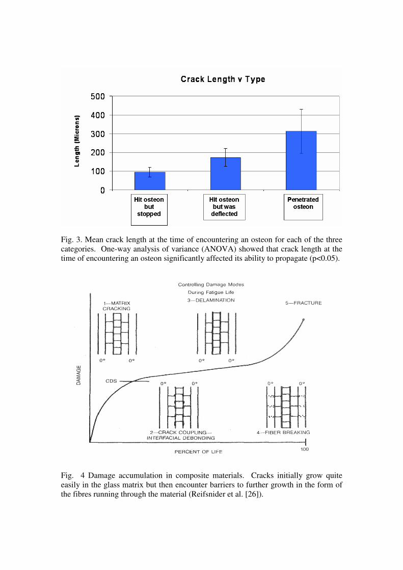
Fig. 3. Mean crack length at the time of encountering an osteon for each of the three
categories. One-way analysis of variance (ANOVA) showed that crack length at the
time of encountering an osteon significantly affected its ability to propagate (p<0.05).
Fig. 4 Damage accumulation in composite materials. Cracks initially grow quite
easily in the glass matrix but then encounter barriers to further growth in the form of
the fibres running through the material (Reifsnider et al. [26]).
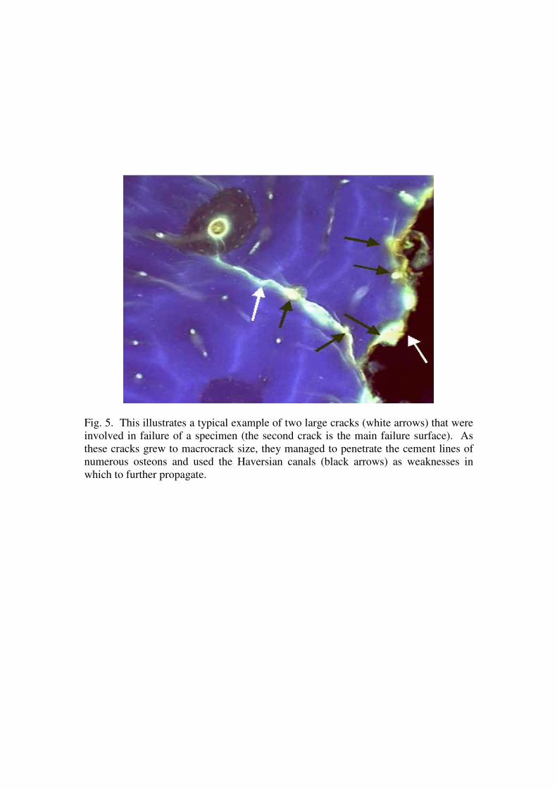
Fig. 5. This illustrates a typical example of two large cracks (white arrows) that were
involved in failure of a specimen (the second crack is the main failure surface). As
these cracks grew to macrocrack size, they managed to penetrate the cement lines of
numerous osteons and used the Haversian canals (black arrows) as weaknesses in
which to further propagate.