bond behavior of a cfrp strengthening system
TRANSCRIPT

7/25/2019 Bond Behavior of a CFRP Strengthening System
http://slidepdf.com/reader/full/bond-behavior-of-a-cfrp-strengthening-system 1/7
Asia-Pacific Conference on FRP in Structures (APFIS 2007)
S.T. Smith (ed)
© 2007 International Institute for FRP in Construction
Bond Behavior of a CFRP Strengthening Systemfor Steel Structures
M. Dawood*, M. Guddati and S. Rizkalla
Department of Civil, Construction and Environmental Engineering,
North Carolina State University, USA*Email: [email protected]
ABSTRACT
This paper summarizes an experimental program supported by an analytical modeling study undertaken to
investigate the bond behavior of carbon fiber reinforced polymer (CFRP) materials used for strengthening steel
structures. The experimental program consisted of three double-lap shear coupon tests and five large-scale beam
tests. Different methods to reduce the bond stress concentrations near the plate ends were investigated including
increasing the length of the splice cover plate and implementing a reverse-tapered plate end configuration.
Three-dimensional linear and non-linear finite element analysis (FEA) was conducted to study the cracking behavior of the splice joints and to determine the effect of the reverse-taper on the interface shear and normal
(peeling) stress distributions near the plate ends. The research findings indicate that implementation of the
reverse taper at the plate ends can double the splice capacity as compared to conventional square plate ends.
Based on the research findings simple design recommendations are presented to increase the ultimate capacity of
splice joints. This paper demonstrates that splice joints can be effectively implemented to facilitate the use of
CFRP strengthening systems for strengthening and repair of long-span steel beams.
KEYWORDS
splice joints, steel, CFRP, reverse taper, FEA, design recommendations, bond, shear stress, peeling stress
INTRODUCTION
Recently, a high-modulus CFRP system has been developed for strengthening and repair of steel bridge girders(Rizkalla and Dawood, 2006). To facilitate implementation of the system to longer span structures, a suitablesplice joint has been developed. Due to the high stiffness of the strengthening materials, plate end debonding is
a critical failure mode which should be carefully considered to avoid premature debonding of the splice plates.
A number of researchers have established analytical models to predict the debonding capacity of bonded joints
using stress based (Albat and Romily, 1999; Smith and Teng, 2001; Stratford and Cadei, 2006) and fracture
mechanics based (Lenwari et al., 2006) approaches. Finite element analyses indicate that careful detailing of
plate ends can significantly reduce bond stress concentrations at these locations, thereby significantly increasing
splice joint capacity (Hildebrand, 1994; Belingardi et al., 2002). Research on spliced connections of plated
beams is limited. Stallings and Porter (2003) tested eight reinforced concrete beams which were strengthened
with CFRP including lap-spliced joints at various locations. They found that failure typically occurred due to
debonding of the splice plates and proposed that splices should be located such that the strain at the splice
location does not exceed an experimentally determined limiting value. To the authors’ knowledge there has not been a comprehensive experimental and analytical study on the performance of CFRP spliced joint connections
for steel structures.
CFRP STRENGTHENING SYSTEM
The unidirectional CFRP plates used in the experimental program were manufactured using high modulus
carbon fibers produced by Mitsubishi Chemical Inc. The CFRP plates were bonded using a two part epoxy
adhesive. The mechanical properties of the fibers, the CFRP plates and the adhesive are presented in Table 1.
Preparation and installation of the strengthening system was conducted according to the recommendations
presented by Schnerch et al. (2007).
PDF created with pdfFactory Pro trial version www.pdffactory.com

7/25/2019 Bond Behavior of a CFRP Strengthening System
http://slidepdf.com/reader/full/bond-behavior-of-a-cfrp-strengthening-system 2/7
Table 1. Mechanical properties of the CFRP strengthening system
CFRP PlateMaterial Property
Fibers
(Mitsubishi, 2004) Reported Measured* Adhesive
**
Elastic Modulus, E 640,000 MPa 450,000 MPa 418,000 MPa 2565 MPa
Ultimate Strength, f frp,u 2600 MPa 1540 MPa 1490 MPa 37.5 MPa
Ultimate Strain, εfrp,u 0.004 0.0033 0.0035 0.015
Fiber Volume Fraction 100 % 70 % N/A N/A
*ASTM D 3039, ** ASTM D 638
EXPERIMENTAL PROGRAM
An extensive experimental program was conducted by Dawood and Rizkalla (2007) to investigate the bond and
splice behavior of CFRP plates. A total of six double-lap shear coupons and nine steel beams were tested. The
parameters considered in the study were the plate end configuration, the length of the splice plates and the use of
mechanical anchorage to resist adhesive normal (peeling) stresses. The following sections briefly summarize the
details of the experimental program for both the coupon tests and the beam tests. The discussion in this paper is
limited to those specimens which included square and reverse-tapered plate end details without mechanical
anchorage. Findings of the complete experimental program are given in Dawood and Rizkalla (2007).
Double-lap Shear Coupon Tests
Three double-lap shear coupons were tested in the first phase of the experimental program. The typical couponsconsisted of two 8 mm thick x 38 mm wide CFRP main plates which were butted together and connected to each
other by two 4 mm thick x 400 mm long adhesively bonded CFRP splice plates.
Two different plate end details were investigated as shown in Table 2. Each specimen configuration was
assigned a two-part specimen ID. The first part indicates the nominal length of the splice plates in millimeters.
The second part of the ID indicates the configuration of the plate ends (Square or Tapered 2 locations). The
square end represents the simplest and most commonly used joint detail while the reverse-tapered joint
configuration was implemented to reduce the bond stress concentrations near the plate ends.
Table 2. Double-lap shear coupon joint configurations
Coupon
ID
Configuration End of Splice
Plate
Center of Splice
Joint
Plate End
Detail
# of
Tests
400-S Square (S) 1
400-T2 Tapered (T2) 2
Beam Tests
Five beams were tested in the second phase of the experimental program to investigate the behavior of CFRP
splice joints under flexural loading. The typical test beams consisted of a W12x30 steel wide flange section with
a structural steel channel welded to the compression flange to simulate the presence of a reinforced concrete
deck. The beams were strengthened with two 2100 mm long CFRP plates which were bonded to the bottom of
the tension flange. The plates were butted at midspan and spliced using a bonded CFRP cover plate. The beamswere tested in a simply supported configuration with a span of 4570 mm and a constant moment region of
1600 mm. The test matrix for the beam tests is presented in Table 4.
Table 3. Beam test matrix
Specimen ID Splice Length (mm) Plate end detail # of Tests
800-S S 2
800-T2800
T2 1
400-S S 1
400-T2400
T2 1
Splice plate
Fillet of adhesive
CL Main plate
Splice plate
Main plateCL
PDF created with pdfFactory Pro trial version www.pdffactory.com

7/25/2019 Bond Behavior of a CFRP Strengthening System
http://slidepdf.com/reader/full/bond-behavior-of-a-cfrp-strengthening-system 3/7
EXPERIMENTAL RESULTS
Doubl e-l ap Shear Coupon Test Results
All of the tested coupons failed by sudden debonding of the CFRP splice plates prior to rupture of the FRP.
Inspection of the failure surface suggests that the failure typically occurred within the thin layer of resin on the
surface of the CFRP strip left by the manufacturing process. The maximum load achieved prior to debonding
and the maximum measured strain in the CFRP main plate are presented in Figure 1 for each of the tested
coupons. The figure also presents the ratio of the maximum strain in the CFRP main plate, εmax, to the rupturestrain of the CFRP, εfrp,u. Inspection of these values indicates that use of the reverse-tapered joint configurationapproximately doubled the maximum capacity of the bonded joint as compared to the square end configuration.
Figure 1. Double-lap shear coupon test results
The measured load-strain behavior at the centerline of the splice joint is given in the graph in Figure 1. The
figure also shows the calculated load-strain behavior for a continuous 8 mm x 35 mm CFRP plate. From the
figure, it can be seen that the initial response of the joints was linear with a higher stiffness than the calculated
stiffness of the continuous FRP plate due to the geometry of the spliced joints. Upon fabrication of the splice
coupons, a small gap was left between the butted ends of the main CFRP plate, which was subsequently filled
with adhesive. This adhesive helped to increase the stiffness of the splice joint.
For the square ended joint configuration, 400-S, the high bond stress concentrations near the square plate ends
within the center of the joint resulted in premature cracking of the adhesive at this location. This can be seen by
the sudden increase of the strain at the 40 kN load level in Figure 1. This increase of strain was accompanied by
a corresponding decrease of the stiffness of the splice. From the figure it can be seen that the final stiffness of
joint 400-S closely matches the theoretical stiffness of the continuous FRP plate, which indicates that the
adhesive at the center of the joint was completely cracked. The reverse-tapered joint configuration, 400-T2,
exhibited a slightly different behavior as shown in the figure. The presence of the tapered plate ends within the
center of the joint helped to reduce the bond stress concentrations at that location which prevented cracking of
the adhesive. Consequently, the joint behavior was linear up to failure with a measured stiffness consistently
higher than the predicted stiffness.
Beam Test Results
All of the beams tested in the second phase of the experimental program failed due to sudden debonding of the
splice plates as shown in the photograph in Figure 2. The failure plane typically extended along the interface
between the CFRP splice plate and the CFRP main plate starting from one end of the splice plate and extending
to the center of the splice joint. The debonded region then continued along the interface between the CFRP main
plate and the tension flange of the steel beam as shown in the figure.
0
50
100
150
200
250
0 0.0005 0.001 0.0015 0.002
Average Measured Strain
A p p l i e d T e n s i o n ,
T ( k N )
400-T2(2)
400-T2(1)
400-S
CFRP
rupture
(465 kN)
TT
Coupon ID Failure
Load
(kN)εmax
max
frp,u
ε
ε
400-S 89 0.00078 0.23
400-T2 (1) 191 0.0015 0.44
400-T2 (2) 228 0.0016 0.47
PDF created with pdfFactory Pro trial version www.pdffactory.com

7/25/2019 Bond Behavior of a CFRP Strengthening System
http://slidepdf.com/reader/full/bond-behavior-of-a-cfrp-strengthening-system 4/7
Figure 2. Typical debonding failure of a splice beam
The maximum load and CFRP strain in the main plate achieved prior to debonding are also given in Figure 2 for
each of the tested beams. The table presents the ratio of the maximum CFRP strain, εmax, to the rupture strain of
the CFRP, εfrp,u. It should be noted that the presence of the splice plate induced a strain concentration in the
main CFRP plate near the toe of the splice. Thus, the reported strain values in Figure 2 are approximately 20 to
30 percent higher than the calculated strain in the CFRP away from the splice joint.
Comparing the maximum load and CFRP strain for the tested beams indicates that increasing the splice length
from 400 mm to 800 mm did not increase the capacity of the splice joint for the square ended joints. However,
including the reverse-tapered plate end approximately doubled the capacity of the splices which confirms the
findings of the double-lap shear tests. The measured load-deflection relationship at midspan of each of the tested
beams is shown in the graph in Figure 2. The dashed line in the graph represents the complete load-deflectionrelationship calculated using a moment-curvature analysis. The figure indicates that all of the beams failed by
debonding of the splice plate prior to reaching the increased yield load level of the strengthened beam.
FINITE ELEMENT ANALYSIS
A 3-D non-linear FEA was conducted to investigate the behavior of the tested double-lap shear coupons. The
tested coupon with the square plate ends, 400-S, was modeled using the ANSYS software package. The CFRP
plates were modeled using 8-node, 3-D elements with three degrees of freedom (dof’s) at each node. The
adhesive materials were modeled using the ANSYS concrete element which is an 8-node, 3-D solid element with
built-in cracking and crushing capabilities. Cracking of the element occurs when the calculated principal stress
at a given location exceeds the specified rupture strength of the material. A maximum element size of 1 mm wasused in all three principal directions. Thus, the adhesive layer was meshed by a single element through the
thickness while the thickness of the CFRP splice plate was modeled using four elements.
The CFRP plates were modeled as orthotropic materials with moduli of elasticity in the longitudinal, E z, and
transverse, Ex and Ey, directions of 418,000 MPa and 10,200 MPa respectively. The shear modulus of the CFRP
was 3750 MPa in all three principle directions. The Poisson’s ratio of the CFRP in the X-Y direction was
specified as 0.39 while in the other two principal directions a Poisson’s ratio of 0.33 was used. The adhesive
was modeled as a linear elastic, isotropic material with an elastic modulus and Poisson’s ratio of 3000 MPa and
0.39 respectively. Within the center of the splice joint, the limiting tension strength of the adhesive was
specified as 37.5 MPa which was obtained from tension tests of representative adhesive coupons. The strength
of the bond interface between the CFRP and the adhesive was obtained from pull-off tests. A total of four pull-
off tests were conducted. Typically a combined interfacial/interlaminar failure was observed near the surface of
the CFRP material. The average and maximum measured bond strengths were 18.4 MPa and 20.2 MPa
0
100
200
300
400
500
600
700
0 10 20 30 40 50
Midspan Deflection (mm)
T o t a l A p p l i e d
L o a d ( k N
800-T2
400-T2
800-S(2)
400-S
800-S(1)
CFRP Rupture
Steel YieldPredicted
behavior
Splice Plate
Main Plate
Splice Plate
Beam IDFailure
Load (kN)εmax max frp,uε ε
800-S(1) 178 0.00082 0.24
800-S(2) 205 0.00104 0.31
800-T2 408 0.00227 0.67
400-S 180 0.00085 0.25
400-T2 340 0.00148 0.44
PDF created with pdfFactory Pro trial version www.pdffactory.com
7/25/2019 Bond Behavior of a CFRP Strengthening System
http://slidepdf.com/reader/full/bond-behavior-of-a-cfrp-strengthening-system 5/7
respectively. The maximum measured pull-off strength was used as the specified tension strength of the bonded
interface between the CFRP and the adhesive in the finite element model.
A linear 3-D finite element analysis of the tested splice beams was also conducted to determine the effect of the
splice plate length and the reverse-tapered joint configuration on the adhesive bond stresses under flexural
loading conditions. The beams were modeled using 20-node brick elements with three dof’s at each node. To
reduce computational expense, only the constant moment region of the beams was modeled and quarter model
symmetry was employed. A stress gradient was applied at the end of the beam section away from midspan tosimulate an equivalent total applied load of 80 kN. Stability of the model was provided by fixing the vertical
dof’s at the top of the beam at midspan. A maximum element edge length of 5 mm was used throughout the
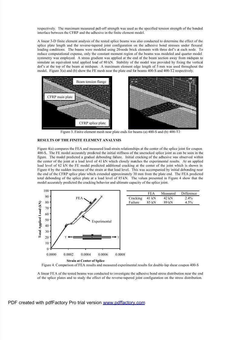
model. Figure 3(a) and (b) show the FE mesh near the plate end for beams 400-S and 400-T2 respectively.
Figure 3. Finite element mesh near plate ends for beams (a) 400-S and (b) 400-T2
RESULTS OF THE FINITE ELEMENT ANALYSIS
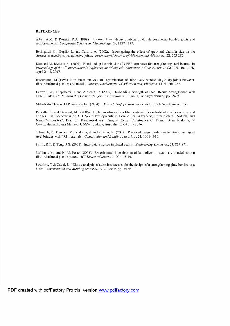
Figure 4(a) compares the FEA and measured load-strain relationships at the center of the splice joint for coupon
400-S. The FE model accurately predicted the initial stiffness of the uncracked splice joint as can be seen in the
figure. The model predicted a gradual debonding failure. Initial cracking of the adhesive was observed within
the center of the joint at a load level of 41 kN which closely matches the experimental results. At an applied
load level of 62 kN the FE model predicted additional cracking at the center of the joint which is shown in
Figure 4 by the sudden increase of the strain at that load level. This was accompanied by initial debonding near
the end of the CFRP splice plate which extended approximately 30 mm from the plate end. The FEA predicted
total debonding of the splice plate at a load level of 85 kN. The values presented in Figure 4 show that themodel accurately predicted the cracking behavior and ultimate capacity of the splice joint.
Figure 4. Comparison of FEA results and measured experimental results for double-lap shear coupon 400-S
A linear FEA of the tested beams was conducted to investigate the adhesive bond stress distribution near the end
of the splice plates and to study the effect of the reverse-tapered joint configuration on the stress distribution.
Beam tension flange
CFRP splice plate
CFRP main plate
(a) (b)
0
1020
30
40
50
60
70
80
90
100
0.0000 0.0002 0.0004 0.0006 0.0008
Strain at Center of Splice
T o t a l A p p l i e d L o a d ( k N )
TT
FEA Measured Difference
Cracking 41 kN 42 kN 2.4%
Failure 85 kN 89 kN 4.5%
FEA
Experimental
PDF created with pdfFactory Pro trial version www.pdffactory.com

7/25/2019 Bond Behavior of a CFRP Strengthening System
http://slidepdf.com/reader/full/bond-behavior-of-a-cfrp-strengthening-system 6/7
The FEA indicated that for the square ended joint configurations, 400-S and 800-S, and the reverse-tapered
configurations, 400-T2 and 800-T2, increasing the length of the splice plate did not affect the stress distribution
near the end of the plate. This is consistent with the findings of the experimental program which indicate that
increasing the splice length did not increase the joint capacity. However, the FEA indicated that the presence of
the reverse-tapered joint configuration significantly decreased the magnitude of the principal bond stress near the
end of the joint. Figure 5(a) and (b) show the shear, normal and principal stress distributions near the end of the
splice plate for beam configurations 800-S and 800-T2 as determined from the FEA. Inspection of the figure
indicates that the presence of the reverse-tapered plate end essentially eliminates the normal (peeling) stressconcentration near the end of the plate thus reducing the maximum principle stress by approximately 60 percent.
This reduction of the principle stress can explain the increase of the joint capacity due to the reverse taper which
was measured in the experimental program.
Figure 5. Bond stresses near the end of the splice plates obtained by FEA for beams (a) 800-S and (b) 800-T2
DESIGN RECOMMENDATIONS
The findings of the experimental and FEA investigations indicate that the capacity of a spliced joint is typically
governed by debonding prior to achieving the rupture strain of the CFRP. Consequently, when strengtheninglonger span beams, splices should be located at points of relatively low moment to prevent a premature failure of
the strengthening system due to debonding of the splice plate. For an 800 mm long reverse-tapered splice, such
as that of beam 800-T2, the maximum strain in the main CFRP plate prior to debonding was 67 percent of the
rupture strain of the CFRP. This corresponds to a maximum strain of 50 percent of the rupture strain at a
location away from the splice plate when accounting for the strain concentration effect. Due to the slight non-
linearity of the moment-curvature relationship of the strengthened beams, the corresponding moment at failure is
approximately 60 percent of the maximum moment applied to the beam. Therefore it is recommended to locate
the splices where the moment is less than 60 percent of the maximum applied factored moment.
CONCLUSIONS
This paper presents an experimental and finite element study of CFRP splice joints for strengthening steel
structures. The findings demonstrate that implementing a reverse-tapered joint configuration is more effective
than increasing the splice length to increase the splice capacity. Finite element analysis indicates that the presence of the reverse taper reduces the bond stress concentration near the end of the CFRP splice plate. Based
on the findings, simplified design recommendations are provided for the design and location of splice joints.
ACKNOWELDGEMENTS
The authors would like to acknowledge the contributions of Mitsubishi Chemical FP America Inc. and the
National Science Foundation (NSF) Industry/University Cooperative Research Center (I/UCRC) on Repair of
Buildings and Bridges with Composites. (RB2C)
-5
0
5
10
15
20
25
30
340 360 380 400 420
Distance from Center of Splice Joint, x (mm)
A d h e s i v e S t r e s s ( M P a ) Normal
Shear
Prinicpal
340 360 380 400 420
Distance from Center of S plice Joint, x (mm)
Normal
Shear
Prinicpal
(a) (b)
PDF created with pdfFactory Pro trial version www.pdffactory.com
7/25/2019 Bond Behavior of a CFRP Strengthening System
http://slidepdf.com/reader/full/bond-behavior-of-a-cfrp-strengthening-system 7/7
REFERENCES
Albat, A.M. & Romily, D.P. (1999). A direct linear-elastic analysis of double symmetric bonded joints and
reinforcements. Composites Science and Technology, 59, 1127-1137.
Belingardi, G., Goglio, L. and Tarditi, A. (2002). Investigating the effect of spew and chamfer size on the
stresses in metal/plastics adhesive joints. International Journal of Adhesion and Adhesives, 22, 273-282.
Dawood M, Rizkalla S. (2007). Bond and splice behavior of CFRP laminates for strengthening steel beams. In
Proceedings of the 3rd
International Conference on Advanced Composites in Construction (ACIC 07), Bath, UK,April 2 – 4, 2007.
Hildebrand, M (1994). Non-linear analysis and optimization of adhesively bonded single lap joints between
fibre-reinforced plastics and metals. International Journal of Adhesion and Adhesives, 14, 4,, 261-267.
Lenwari, A., Thepchatri, T and Albrecht, P. (2006). Debonding Strength of Steel Beams Strengthened with
CFRP Plates, ASCE Journal of Composites for Construction, v. 10, no. 1, January/February, pp. 69-78.
Mitsubishi Chemical FP America Inc. (2004). Dialead: High performance coal tar pitch based carbon fiber.
Rizkalla, S. and Dawood, M. (2006). High modulus carbon fiber materials for retrofit of steel structures and bridges. In Proceedings of ACUN-5 “Developments in Composites: Advanced, Infrastructural, Natural, and
Nano-Composites”, Eds: Sri Bandyopadhyay, Qinghua Zeng, Christopher C. Bernd, Sami Rizkalla, N
Gowripalan and Janis Matison, UNSW, Sydney, Australia, 11-14 July 2006.
Schnerch, D., Dawood, M., Rizkalla, S. and Sumner, E. (2007). Proposed design guidelines for strengthening of
steel bridges with FRP materials. Construction and Building Materials, 21, 1001-1010.
Smith, S.T. & Teng, J.G. (2001). Interfacial stresses in plated beams. Engineering Structures, 23, 857-871.
Stallings, M. and N. M. Porter (2003). Experimental investigation of lap splices in externally bonded carbon
fiber-reinforced plastic plates. ACI Structural Journal, 100, 1, 3-10.
Stratford, T & Cadei, J. “Elastic analysis of adhesion stresses for the design of a strengthening plate bonded to a
beam,” Construction and Building Materials, v. 20, 2006, pp. 34-45.
PDF created with pdfFactory Pro trial version www pdffactory com