boiler room monitoring system mechatronics project project...
TRANSCRIPT

Boiler Room Monitoring System
Mechatronics Project
PROJECT REPORT
Spring-2009
Submitted by Team 1
Alfonso Cozzo Vinay K.M Sam Wan

Topic Boiler Room Monitoring System (Hot water system Natural gas burner) Preventive maintenance that saves you money
Purpose
The scope of the project includes the study of the various stages of a Residential Boiler and its corresponding parameters. With our project we aim at achieving the following:
Maintenance of the system to ensures extended life of the system, increase system gain and also safe operation.
The aim is to constantly improve processes and thus reduce waste even more. Improving efficiency of the system reduces excess energy utilization in heating
the system Provide a cost effective way to read boiler parameter values and have an alarm
system setup for the user to be informed of the system failures. Develop a user friendly device to monitor the system.
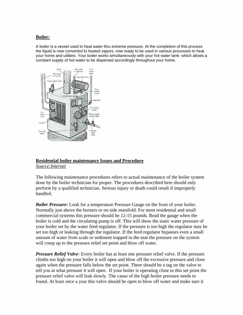
Boiler: A boiler is a vessel used to heat water thru extreme pressure. At the completion of this process the liquid is now converted to heated vapors, now ready to be used in various processes to heat your home and utilities. Your boiler works simultaneously with your hot water tank- which allows a constant supply of hot water to be dispersed accordingly throughout your home.
Residential boiler maintenance Issues and Procedure Source:Internet The following maintenance procedures refers to actual maintenance of the boiler system done by the boiler technician for proper. The procedures described here should only perform by a qualified technician. Serious injury or death could result if improperly handled. Boiler Pressure: Look for a temperature Pressure Gauge on the front of your boiler. Normally just above the burners or on side manifold. For most residential and small commercial systems this pressure should be 12-15 pounds. Read the gauge when the boiler is cold and the circulating pump is off. This will show the static water pressure of your boiler set by the water feed regulator. If the pressure is too high the regulator may be set too high or leaking through the regulator. If the feed regulator bypasses even a small amount of water from scale or sediment trapped in the seat the pressure on the system will creep up to the pressure relief set point and blow off water. Pressure Relief Valve: Every boiler has at least one pressure relief valve. If the pressure climbs too high on your boiler it will open and blow off the excessive pressure and close again when the pressure falls below the set point. There should be a tag on the valve to tell you at what pressure it will open. If your boiler is operating close to this set point the pressure relief valve will leak slowly. The cause of the high boiler pressure needs to found. At least once a year this valve should be open to blow off water and make sure it

has not plugged up with sediment and scale. Check the boiler pressure before you begin, if it is close to the set point the relief valve will not close right away. The outlet of the relief valve should be piped to 6" above the floor and to a place where it will not cause water damage if opened. This makes annual blow down on the relief valve easy. It can be piped directly to a floor drain, but the outlet should be open so any leakage can be detected. If the unit is not piped to a deain use a bucket to catch the water if needed. Make sure you know where the boiler feed water shut off is, just in case. With the boiler off and cold, lift the manual lever and blow off some water for a few seconds and let the lever snap back. There should be a good gush that comes out and be fairly clear water. If the valve has small leaks after wards, just open it again and let some more water out, sediment can become trapped in the seat causing minor leakage. If the valve will not close at all shut the boiler water feed off and remove and replace the relief valve. If no water comes out, then the valve is plugged or there is no water in the boiler. In either case do not use the boiler until the problem is identified and repaired. Circulating Pump: Most boiler pumps require lubrication for the motor and the pump. The motor normally requires a few drops and the pump bearing should have and oil port. This needs to be filled to keep the oil wicks wet. Refer to the manufacturer instructions for lubrication procedure for you pump. There maybe more than one pump on you system. Some of the smaller cartridge style pumps do not require any maintenance. The volume of water circulated by the pump is very important to the boiler operation. Too little water will boil inside the heating coil and plug it with scale. This will sound like a crackling sound inside the boiler when the burner is operating. A single pressure gauge piped across the pump inlet and outlet is the best way to monitor pump performance. As the pressure difference increases across the pump the lower the volume. The lower the pressure differences the higher the volume. Another way to check water flow is by temperature. When the burner is operating check the temperature rise through the boiler. Most are designed for a 10%F TD with nominal water flow. If the TD is higher 25%F or more the water flow is too low and can start to boil off in the heating coil. Temperature Set point: There could be up 4 temperature controller on a hot water boiler system. Room Thermostat, Boiler Water Temperature Control, Circulation pump temperature control, and the safety high limit control. Operating set point is normally an external control to the boiler. It controls the temperature of the circulating water. This can be a fixed set point set around 160°F to 180°F or preferably an Outdoor reset controls will raise the boiler water temperature the colder it gets outside and lower the water temperature the warm it gets outside. Outdoor reset controls can save a lot of money on a boiler system. It also has a minimum boiler temperature of 130%F to prevent condensation inside the boiler and will shut the boiler off it get too warm outside. Room Thermostat can be used to open a zone valve, which in turn enables the boiler, or enables the boiler directly. Circulation thermostats are used to start and stop the circulation pump and can be

combined in the same control as the high limit. Normally the circ pump should be set around 90°F-100°F. On atmospheric boiler with draft hoods after the burner shuts down the continued draft starts to cool the water .Air from inside the boiler room is cooler then the water temperature in the boiler system. By shutting down the boiler circuit pump after the water cools helps to reduce this heat loss. An Automatic draft hood vent damper can also prevent heat loss. High limit control is a safety limit switch that will shut the burner off if the water temperature gets too high. Check with the boiler manufacturer for the proper set point for your system. These are normally around 200%F but can be higher or lower. I have often found these being used as the operating control for the boiler because they are shipped with the boiler and the installer does not add the external operating control leaving the boiler without a safety high limit control. Pilot Assembly:
Issue with the Pilot Light frequently going out: The most common is a bad thermocouple. A thermocouple sends a signal to the main gas control on the water heater telling it the pilot is on. If the thermocouple goes bad, it will send a false signal and the pilot will go out. Solution to the above issues is our project

Project description
Picture of the entire Setup A boiler room is a place was no one goes until there is a problem. However most
of the time no one knows there is a problem with the heating system until it is too late and the house is ice cold or there is no more hot water. To help prevents such problems we suppose using an early warning system to detect a minor problem before it becomes a major problem. One of the most common places of failure on a boiler is in the pilot assembly. The pilot light is controlled by a thermocouple which pulls in the presence of flame. However, if the thermocouple malfunctions than the heat cannot turn on and tenant’s complaints will soon follow. To help fix the problem more quickly we suppose using a photo resistor to monitor the state of the pilot and report any problems to the owner of the house or the land lord. Another problem that plagues Hot water boilers is the accumulation of rust in the boiler water. This rust increase fuel costs and cuts down the efficiency of the system which means that the rust is hitting you were it hurts in the wallet. It is recommended that you change the water in your system every couple of months to prevent this build up but no one does. Therefore we are proposing a monitoring system that will use a boilers existing gauge glass to monitor rust levels. The system will than be able to change water to correct the rust problem. Another problem with hot water system is found in the expansion tank. Many times the expansion tanks ruptures and fills with water causing failure and a very soggy basement. Therefore a system involving humidity to monitor the pressure relief value would be very useful. The system will be connected to a control panel located in the superintendent’s apartment or some other high traffic areas were it will likely be checked like near the main entrance. The panel consists of a group of LEDS and speakers that will alert people to the presence of a problem.
Another part of the system will be a hand held diagnostic tool that can be used to test different parts of the boiler. One such test could utilize a non contact temperature sensor to test if the circulator pump is running or not. Most boiler rooms are noisy and most circulators run silent which makes it hard to determine if they are running. However by taking one temperature on the header line before the flow control and one after the flow control you can tell if the circulator is running. This is possible because of the flow control value which only allows for heat to escape from the boiler only when the circulator is on. So by using the temperature difference between the two lines you can better understand what is going wrong with your system. You can determine if the circulator is working or not or if the flow control value is malfunctioning. This system could also be used on a boiler with zone values to determine if all the zones of your system are working. In the future we could create different platforms for different boilers systems with different sets of problems. For example a model designed for Oil burners which use sensor so detect dirty oil filters and supply line problems Also fuel gauges that monitor oil levels to insure that you receive the correct amount of oil from your supplier.

Basic boiler room set up with a hot water heater and a gas fired hot water boiler. This diagram shows a representation of the BS2 wired to monitor these devices as well as the led alert panel.

Analysis of design Pilot Assembly:-
The Pilot flame detector The Pilot flame detector consists of a photo resistor connected in a RC circuit. In the RC circuit the Photo resistor works as a variable resistor. Therefore the RC time changes in the presence of different values of light. Therefore the program checks if a certain value of light is present. In order words it checks if the pilot light is on. If the pilot light is off than a warning light is set off and an alarm sounds The Pilot flame detector Code HIGH 15 PAUSE 100 RCTIME 15, 1, Inputtime DEBUG HOME , "Light = ", DEC4 Inputtime IF (400<Inputtime) THEN HIGH 5 FREQOUT 11 ,1500, 2000 ’Speaker activated ENDIF Here the RCTIME circuit with the Photo-resistor as the resistance is used to determine the state of light (On/Off). If the value of the RCTIME (Inputtime) is greater than the threshold value of 400(value determined by experimentation) then it implies that the Pilot Flame is Off and thus Alarms.

The Pilot flame detector Electronic circuits
Photo-resistor Rctime circuit The Dirty Water Detector: Photo of Valve assembly

The Dirty Water detector consists of a photo resistor connected in a RC circuit. In the RC circuit the Photo resistor works as a variable resistor. Therefore the RC time changes in the presence of different values of light. Therefore the program checks if a certain value of light is present in order words it checks if the water in the gauge glass is dirty. If the water is dirty a motor is used to drain water from the boiler. After a set time the value closes and checks the water again. This process is repeated until the water is clean The Dirty Water Code 'Water Check Program 'LED ON HIGH 13 HIGH 2 PAUSE 100 RCTIME 2, 1, Inputtime IF (50<Inputtime) THEN GOSUB A ‘ Speaker Program DEBUG HOME ,CR DEBUG "Light = ", DEC4 Inputtime ‘ Clean up the water by opening valve and does the check twice, if still dirty jumps out to ‘ avoid the system from continuous cleaning IF number <2 THEN HIGH 6 FOR i=0 TO 90 ‘Counter clockwise rotation for opening of valve PULSOUT 14,500 PAUSE 20 NEXT PAUSE 1000 FOR i=0 TO 90 ‘Clockwise rotation for closing of valve PULSOUT 14,1000 PAUSE 20 NEXT

PAUSE 100 number=number+1 ‘Increment the counter ELSE HIGH 9 ENDIF LOW 6 ENDIF DEBUG HOME, CR DEBUG "light = ", DEC4 Inputtime The RC Circuit is used to check the purity of water flow in the water circulation system. When the value of the rctime is greater than 35 it implies the water is dirty and so the valve circuit is activated to open the valve and allow the flow of fresh water by draining of the dirty water. The valve is closed after a period of time which is based on the water flow rate. In the ‘FOR’ loop for the above code the values are chosen based on the required rotation of the valve to open and close. The Dirty Water Electronic circuits
LED Circuit
Photo-resistor Rctime circuit Thermostat lock Box Alarm

Photo of Box Alarm The Thermostat lock Box Alarm detector consists of a button connected in circuit to a pin on the BS2 . In the circuit the Photo resistor works as a normaly closed touch sensor. So as long as the box stays closed the alarm will not sound If the value of the button changes due to the box opening the alarm will sound. The program checks if the button value is high. If the box is opened than an warning light goes on and a alarm sound. This allows the landlord to caught someone who is tampering with the Thermostat. Thermostat lock Box Alarm Code IF IN12=0 THEN ‘check for Button being pressed HIGH 7 HIGH 1 FREQOUT 11 ,1500, 2000 ELSEIF IN12=1 THEN ENDIF Thermostat lock Box Alarm Circuit

The Water Detector: The Water detector consists of a humidity sensor. The program checks if a certain value of humidity is present in other words it checks if the water leaking from the pressure relief value. If water is present that a warning led will light and the alarm will sound
HS1101- Humidity Sensor The Water Detector Alarm Code RHconstant CON 12169 HIGH 0 PAUSE 1 RCTIME 0,1, Inputtime Inputtime=Inputtime*100 Humidity = (Inputtime-RHconstant)/24 IF (humidity >50) THEN HIGH 8 FREQOUT 11 ,1500, 2000 ENDIF DEBUG HOME, "relative Humidity = ", DEC Humidity, "%" PAUSE 100

The RHconstant which is 12169is selected by calibration that is by measuring the humidity outside using another measuring device. The RHconstant value is made to match the output to actual measured value. This is a trial method to set the value. The Water Detector Alarm Circuit
Humidity Sensor Temperature sensor: MLX90614 Infrared Thermometer Module
BASIC Stamp pin connections:

MLX90614 Module - Function GND - Ground link between microcontroller / MLX90614 Module - Gnd 5V - Voltage link between microcontroller / MLX90614 Module ) - 5V (VDD) SIG - Serial I/O link between microcontroller / MLX90614 Module - Any I/O pin ALR - Alarm control output, high on alarm - optional RST - Reset link to coprocessor, pull low to high for reset - optional Applications:
Sensing and measuring surface temperatures without surface contact Alarming alert for over temperature conditions Temperature sensing element for residential, commercial and industrial building
air conditioning Industrial temperature control of moving parts such as die protection Human or animal presence detection Movement detection Multiple zone temperature control – up to 100 sensors can be read via common 2
wires Thermal relay and alert Body temperature measurement
Display menu board:

The display panel consists of a series of LEDs, speakers and two buttons. The LED will light according to which alarm has been tripped in the system. The LED will stay on until the reset button has been pressed by the user. Also the Speakers will sound until the mute button is pressed by the user Display Circuit Circuit for display panel Complete system The complete system combines the proceeding programs into one big program and checks each sensor one at a time. Than if there is any problem than it turns on the display panel Complete System Code

' {$STAMP BS2} ' {$PBASIC 2.5} ‘Defining the variables Inputtime VAR Word i VAR Byte number VAR Nib mute VAR Nib mute=0 OUTL =%000000000 OUTH = %000000000 DIRH = %111111111 DIRH = %111111111 Main: DO ‘Pilot assembly check program HIGH 15 PAUSE 100 RCTIME 15, 1, Inputtime DEBUG HOME ,"Light = ", DEC4 Inputtime IF (200<Inputtime ) THEN HIGH 5 HIGH 1 GOSUB A ‘ Speaker Program ENDIF 'Water Check Program 'LED ON HIGH 13 HIGH 2 PAUSE 100 RCTIME 2, 1, Inputtime IF (50<Inputtime) THEN GOSUB A ‘ Speaker Program DEBUG HOME ,CR DEBUG "Light = ", DEC4 Inputtime ‘ Clean up the water by opening valve and does the check twice, if still dirty jumps out to ‘ avoid the system from continuous cleaning IF number <2 THEN HIGH 6 FOR i=0 TO 90 ‘Counter clockwise rotation for opening of valve PULSOUT 14,500

PAUSE 20 NEXT PAUSE 1000 FOR i=0 TO 90 ‘Clockwise rotation for closing of valve PULSOUT 14,1000 PAUSE 20 NEXT PAUSE 100 number=number+1 ‘Increment the counter ELSE HIGH 9 ENDIF LOW 6 ENDIF DEBUG HOME, CR DEBUG "light = ", DEC4 Inputtime 'Alarm Box IF IN12=0 THEN HIGH 7 HIGH 1 FREQOUT 11 ,1500, 2000 ELSEIF IN12=1 THEN ENDIF 'Humdity RHconstant CON 12169 HIGH 0 PAUSE 1 RCTIME 0,1, Inputtime Inputtime=Inputtime*100 Inputtime = (Inputtime-RHconstant)/24 IF (Inputtime >60) THEN HIGH 8 HIGH 1 GOSUB A ‘ Speaker Program ENDIF DEBUG HOME, CR ,CR DEBUG "relative Humidity = ", DEC Inputtime, "%" PAUSE 1000

'Check For User Input LOOP WHILE (IN3=0 AND IN4 =0) IF IN3=1 THEN LOW 1 LOW 5 LOW 6 LOW 7 LOW 8 LOW 9 Mute =0 GOTO main ELSEIF IN4=1 THEN Mute = 1 GOTO main ENDIF A: ‘ Speaker Program IF (mute =0) THEN FREQOUT 11 ,1500, 2000 ENDIF RETURN Diagnostic Temperature Sensor Code Main: LOW 4 ’Turns off the light probe GOSUB M ‘ Prevent Button Jump DIRL = %11111111 TxPin CON 0 Baud19200 CON 32 DO ’Display first option and wait for user input HIGH TxPin ' Set pin high to be a serial port PAUSE 100 ' Pause for Serial LCD to initialize SEROUT 12, Baud19200, [$0C] ' clear SEROUT 12, Baud19200, [" Check Boiler B1"] SEROUT 12, Baud19200,[$94] SEROUT 12, Baud19200, ["next option B2."] PAUSE 10 IF IN11=1 THEN 'Check Boiler B1 GOTO A 'Check Boiler Ciculator ELSEIF IN10=1 THEN 'NEXT opition

GOTO B 'TEMPERATURE MENU OPTION ENDIF LOOP 'UNTIL IN11=1 OR IN10=1 ' Waits FOR the ON BUTTON TO be pushed" A: 'Check Boiler Ciculator DO LOOP UNTIL IN11=0 AND IN10=0 SEROUT 12, Baud19200, [$0C] ' clear SEROUT 12, Baud19200, ["T1 U FC T2 O FC."] ‘ Temp 1 under flow control and temp2 over flow control SEROUT 12, Baud19200,[$94] SEROUT 12, Baud19200, ["Press Button 1 ."] DO LOOP UNTIL IN11 =1 'GOSUB M 'SEROUT 12, Baud19200, [$0C] ' clear 'SEROUT 12, Baud19200, ["Point to spot"] 'SEROUT 12, Baud19200,[$94] 'SEROUT 12, Baud19200, ["B1 Store T."] 'DO 'LOOP UNTIL IN11 =1 GOSUB M Reset CON 15 Alarm CON 14 Sensor CON 13 ' -----[ Constants ]------------------------------------------------------- baud CON 84 xslave CON $35 'slave address ' -----[ Variables ]------------------------------------------------------- temperature VAR Word tempL VAR temperature.LOWBYTE tempH VAR temperature.HIGHBYTE temperature2 VAR Word tempL2 VAR temperature2.LOWBYTE

tempH2 VAR temperature2.HIGHBYTE DO GOSUB K 'TAKE TEMPERATURE 1 LOOP UNTIL IN11=1 GOSUB M 'ELIMINATE BUTTON JUMP DO GOSUB L 'TAKE TEMPERATURE 2 LOOP UNTIL IN11=1 GOSUB M ‘Comparing temperature values IF (temperature < temperature2-2) THEN PAUSE 100 ' Pause for Serial LCD to initialize SEROUT 12, Baud19200, [$0C] ' clear SEROUT 12, Baud19200, ["error TEST Again"] 'SEROUT 12, Baud19200,[$94] 'SEROUT 12, Baud19200, ["test again" ] PAUSE 6000 LOW 4 GOTO Main ELSEIF (temperature > temperature2+2) THEN PAUSE 100 ' Pause for Serial LCD to initialize SEROUT 12, Baud19200, [$0C] ' clear SEROUT 12, Baud19200, [" Circulator OFF"] 'SEROUT 12, Baud19200,[$94] 'SEROUT 12, Baud19200, ["Check FC" ] PAUSE 6000 LOW 4 GOTO Main ELSE PAUSE 100 ' Pause for Serial LCD to initialize SEROUT 12, Baud19200, [$0C] ' clear SEROUT 12, Baud19200, [" CIRCULATOR WORKING"] 'SEROUT 12, Baud19200,[$94] 'SEROUT 12, Baud19200, [" Check elsewhere" ] B: 'TEMPERATURE MENU OPTION SEROUT 12, Baud19200, [$0C] ' clear SEROUT 12, Baud19200, ["Check TEMP B1."] SEROUT 12, Baud19200,[$94] SEROUT 12, Baud19200, ["next option B2."]

GOSUB M 'ELIMINATE BUTTON JUMP DO IF IN11=1 THEN 'Check temp B1 GOTO C 'TEMPERATURE PROGRAM ELSEIF IN10=1 THEN 'NEXT opition GOTO D ENDIF LOOP C: 'TEMPERATURE PROGRAM GOSUB M DO GOSUB K 'Take Temp1 LOOP UNTIL IN11=1 GOTO Main D:'HUMDTY MENU OPTION SEROUT 12, Baud19200, [$0C] ' clear SEROUT 12, Baud19200, ["Check HUM."] SEROUT 12, Baud19200,[$94] SEROUT 12, Baud19200, ["next option B2."] GOSUB M 'ELIMINATE BUTTON JUMP DO IF IN11=1 THEN 'Check HUM B1 GOTO E ELSEIF IN10=1 THEN 'NEXT opition GOTO F ENDIF LOOP E: 'HUMDITY TESTOR DO LOOP UNTIL IN11=0 AND IN10=0 RHconstant CON 12169 DO time VAR Word Humidity VAR Word HIGH 0 PAUSE 1 RCTIME 0,1, time time=time*100 Humidity = (time-RHconstant)/24

SEROUT 12, Baud19200, [$0C] ' clear SEROUT 12, Baud19200, ["HUM.",DEC Humidity] SEROUT 12, Baud19200,[$94] SEROUT 12, Baud19200, ["B2 for Menu"] 'DEBUG HOME, "relative Humidity = ", DEC Humidity, "%" PAUSE 100 LOOP UNTIL IN10=1 GOTO main F: 'THERMOSTAT MENU OPTION SEROUT 12, Baud19200, [$0C] ' clear SEROUT 12, Baud19200, ["Check thermo."] SEROUT 12, Baud19200,[$94] SEROUT 12, Baud19200, ["next option B2."] GOSUB M 'ELIMINATE BUTTON JUMP DO IF IN11=1 THEN 'Check THERMOSTAT B1 GOTO G ELSEIF IN10=1 THEN 'NEXT opition GOTO H ENDIF LOOP G: 'THERMOSTAT TESTOR GOSUB M 'ELIMINATE BUTTON JUMP SEROUT 12, Baud19200, [$0C] ' clear SEROUT 12, Baud19200, ["LED ON WORKING."] SEROUT 12, Baud19200,[$94] SEROUT 12, Baud19200, ["LED OFF BROKE"] DO HIGH 1 LOOP UNTIL IN10=1 LOW 1 GOTO main H: 'STEAM TRAP TESTOR SEROUT 12, Baud19200, [$0C] ' clear SEROUT 12, Baud19200, ["STEAM TRAP TEST."] SEROUT 12, Baud19200,[$94] SEROUT 12, Baud19200, ["next option B2."] GOSUB M

DO IF IN11=1 THEN 'Check STEAM TRAP B1 GOSUB I ELSEIF IN10=1 THEN 'NEXT opition GOTO Main ENDIF LOOP I: 'Check Steam Trap GOSUB M SEROUT 12, Baud19200, [$0C] ' clear SEROUT 12, Baud19200, ["T1 B ST T2 A ST."] SEROUT 12, Baud19200,[$94] SEROUT 12, Baud19200, ["Press Button 1 ."] DO LOOP UNTIL IN11 =1 GOSUB M SEROUT 12, Baud19200, [$0C] ' clear SEROUT 12, Baud19200, ["Piont to spot"] SEROUT 12, Baud19200,[$94] SEROUT 12, Baud19200, ["B1 Store Temp."] DO LOOP UNTIL IN11 =1 GOSUB M DO GOSUB K 'Take Temp1 LOOP UNTIL IN11=1 GOSUB M DO GOSUB L 'TAKE TEMP2 LOOP UNTIL IN11=1 GOSUB M DEBUG DEC temperature DEBUG DEC temperature2

IF (temperature < temperature2-2) THEN PAUSE 100 ' Pause for Serial LCD to initialize SEROUT 12, Baud19200, [$0C] ' clear SEROUT 12, Baud19200, ["error"] SEROUT 12, Baud19200,[$94] SEROUT 12, Baud19200, ["test again" ] PAUSE 6000 LOW 4 GOTO Main ELSEIF (temperature > temperature2+2) THEN PAUSE 100 ' Pause for Serial LCD to initialize SEROUT 12, Baud19200, [$0C] ' clear SEROUT 12, Baud19200, ["Steam Trap good"] PAUSE 6000 LOW 4 GOTO Main ELSE PAUSE 100 ' Pause for Serial LCD to initialize SEROUT 12, Baud19200, [$0C] ' clear SEROUT 12, Baud19200, ["Steam Trap Fail "] PAUSE 6000 LOW 4 GOTO Main ENDIF K: 'Take Temp 1 HIGH 4 SEROUT Sensor,baud,[0,"!TEMR",xslave,$07] SERIN Sensor,baud,[tempL,tempH ] temperature = (temperature/100*2)-273 'Celsius temperature = ((9*temperature/5)+32) ' F PAUSE 100 ' Pause for Serial LCD to initialize SEROUT 12, Baud19200, [$0C] ' clear SEROUT 12, Baud19200, ["Temperature"] SEROUT 12, Baud19200,[$94] SEROUT 12, Baud19200, [DEC temperature ] RETURN L:'TAKE TEMP2 HIGH 4 SEROUT Sensor,baud,[0,"!TEMR",xslave,$07] SERIN Sensor,baud,[tempL2,tempH2] temperature2 = (temperature2/100*2)-273 'Celsius temperature2 = ((9*temperature2/5)+32) ' F

PAUSE 100 ' Pause for Serial LCD to initialize SEROUT 12, Baud19200, [$0C] ' clear SEROUT 12, Baud19200, [" temperature 2"] SEROUT 12, Baud19200,[$94] SEROUT 12, Baud19200, [DEC temperature2 ] RETURN M: DO LOOP UNTIL IN11=0 AND IN10=0 RETURN Testing the Circulator
• Use the BS2 and a temperature sensor to take non contact temperature measurements
• Reading one is taken between the outlet of the boiler and the flow control • Reading two is taken after the flow control • By comparing the two values you can know if the circulator is working
Three possible outcomes
• Temp1 = Temp 2 • This means the circulator and flow control are working correctly • Temp1 > Temp2 • This means either the circulator or flow control not working correctly • Temp1 < Temp2 • The reading are faulty and you must try again
Testing a steam trap
• Keeps Steam in your heater and out of your return lines • Hot steam caused the trap to close • Cooler steam will cause the trap to open • When the trap malfunctions the efficiently of your system drops significantly
The three possible out comes
• Temp1 = Temp 2 • This means that the steam trap is malfunctioning • Temp1 > Temp2 • This means the steam trap is working correctly • Temp1 < Temp2 • The reading are faulty and you must try again

Humidity tester • Take readings of humidity around the boiler room can expose potential problems • For Example a leaking hot water heater
Temperature sensor • Taking Temperature readings inside and outside of the boiler room can be very
useful • Taking temperature reading at all the radiators can tell you how the system is
working • Also taking temperature readings at the hot water heater can prevent scalding
Continuity tester • Can Be used to test all the Safety switches on your boiler • Can also be used to Check for Proper Thermostat operation • Thermostat test
Prototype Cost Bill of materials: SERIAL NO.
ITEM NAME QTY UNIT PRICE AMOUNT
1 BASIC Stamp 2 Module 2 49 98
2 BS2 Board of Education 2 69.99 139.98
3 HS1101 Humiditysensor 2 4.99 9.98
4 MLX90614 Infrared Therm 10 Deg
1 59.99 59.99
5 PULSED PIEZO BUZZ 1 5.49 5.49
6 5000MCD JMBO LED 1 2.79 2.79
7 Resistors PK5 1 MEG 1/4 W 1 0.99 0.99
8 ULTRA BRIGHT UV LED PK2 1 1.69 1.69
9 TLC555 TIMER 1 1.69 1.69
10 UNIVERSAL BREADBOARD 301 2 7.99 15.98
11 PK10 MINI CLIPS 1 3.59 3.59
12 90'#22 SOLID UL 1 7.99 7.99
13 UNIVERSAL BREADBOARD 102L 1 19.99 19.99
14 SHIPPING 1 17.23 17.23
15 Standard Servo motor 1 12.99 12.99
16 LCD 1 20 20
TOTAL USD$ 418.37

Further Improvisations: Standardization is necessary for approved processes and flexibility. Standards are oriented on best-in-class and are not static – this means they are permanently developed. The use of standardized sensors ensures system accuracy Cost Reduction: Use of appropriate cost effective sensors will serve the purpose. Remote Access: Incorporating internet access or mobile technology would enable the users to have access remotely. One can receive text messages to the mobile phone

thousands of miles away from home of an alarm triggered. Also system can be web -internet enabled to control the boiler parameters. The system could be shut-off if required.
Conclusion: We successfully utilized the BS2 Parallax Kit to achieve the purpose of our project. We made use of the available low cost sensors and circuits to monitor the Home Boiler system.