boiler – fundamentals and best practices · pdf fileboiler - fundamentals steam...
TRANSCRIPT

Boiler Boiler –– Fundamentals Fundamentals and Best Practicesand Best Practices
By:

Boiler - Fundamentals
Steam production and steam uses
Steam purity and steam quality
Types of boilers
Basic boiler principles
Basic boiler calculations

Steam Productionand
Steam Uses
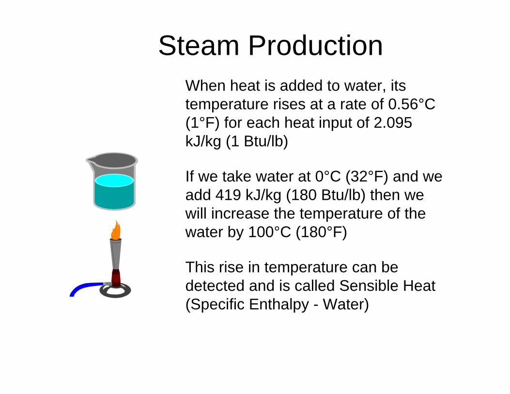
Steam ProductionWhen heat is added to water, its temperature rises at a rate of 0.56°C (1°F) for each heat input of 2.095 kJ/kg (1 Btu/lb)
If we take water at 0°C (32°F) and we add 419 kJ/kg (180 Btu/lb) then we will increase the temperature of the water by 100°C (180°F)
This rise in temperature can be detected and is called Sensible Heat (Specific Enthalpy - Water)
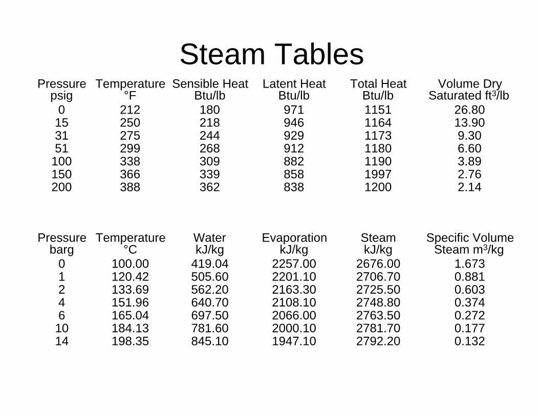
Steam TablesPressure
psigTemperature
°FSensible Heat
Btu/lbLatent Heat
Btu/lbTotal Heat
Btu/lbVolume Dry
Saturated ft3/lb0 212 180 971 1151 26.8015 250 218 946 1164 13.9031 275 244 929 1173 9.3051 299 268 912 1180 6.60
100 338 309 882 1190 3.89150 366 339 858 1997 2.76200 388 362 838 1200 2.14
Pressure barg
Temperature °C
Water kJ/kg
Evaporation kJ/kg
Steam kJ/kg
Specific Volume Steam m3/kg
0 100.00 419.04 2257.00 2676.00 1.6731 120.42 505.60 2201.10 2706.70 0.8812 133.69 562.20 2163.30 2725.50 0.6034 151.96 640.70 2108.10 2748.80 0.3746 165.04 697.50 2066.00 2763.50 0.27210 184.13 781.60 2000.10 2781.70 0.17714 198.35 845.10 1947.10 2792.20 0.132

Steam ProductionAt normal atmospheric pressure, any further addition of heat to water at 100°C will not increase the temperature but will convert some of the water into steam
In order to convert water into steam 2,257 kJ/kg (971Btu/lb) of additional heat must be added
This cannot be detected as a rise in temperature and is called the Latent Heat of Vaporisation (Specific Enthalpy - Evaporation)
Steam

Steam Production
Total Heat of Steam = Sensible Heat + Latent Heat of Vaporisation
Specific Enthalpy :Steam = Water + Evaporation
Thus the Total Heat of Steam (Specific Enthalpy - Steam) is 2,676 kJ/kg (1151 Btu/lb)
This data is found in Steam Tables
Steam

Steam Production
From steam tables we can see that the total heat of steam does not vary a great deal as the boiler pressure increase
The boiling point (b.p.) increases as the pressure increases
Thus the sensible heat increases as the pressure increases, and the latent heat decreases
Boiler pressures are expressed in psia, psig, bar, kg/cm2, kpa
Steam

Steam Uses
Space heating
Drying - paper mill
Process heating
Sterilisation
Humidification
Power generation

Steam Purityand
Steam Quality

Steam Purity
Steam purity is an expression of the quantity of non water components in the steam
Components can be dissolved in the steam, dissolved in water droplets entrained in the steam or carried as discrete solid particles in the steam
Steam impurities are normally expresses as a quantity in parts per million (ppm) or parts per billion

Steam Quality
Steam quality relates to the quantity of moisture present in the steam
100% quality specifying no moisture content
0% quality specifying all liquid
Liquid droplets entrained in the steam leaving a boiler contain dissolved solids

Types of Boilers

Types of Boilers
• Fire Tube
• Water Tube
• Waste Heat

Types of Boilers
Fire Tube Boilers
Water Tube Boilers
Waste Heat Boilers
Low Pressure Systems
Medium to High Pressure Systems
Process applications HRSG

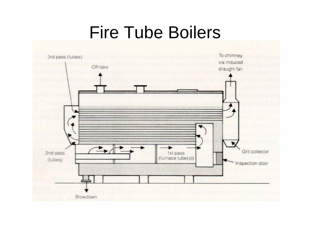
Fire Tube Boilers
Also referred to as smoke tube boilers, shell boilers, package boilers
Multiple gas paths - 2, 3 and 4 pass
Internal furnace or fire box as the 1st pass
Dry back or wet back design
Single fuel or dual fuel design
Little or no steam separation equipment
Fire Tube Boilers

Fire Tube Boilers

Typical designs are O, D and A type boilers
Steam separation equipment - drum furniture
Cyclone separatorsDemister padsBaffle plates
Have economisers and superheaters
Large water tube boilers are field erected and may be unique design
Fire Tube Boilers

WATER WALLS
SUPERHEATER
SCREEN TUBES
STEAM DRUM
MUDDRUM
ECONOMISER
AIR HEATER
RISERSDOWNCOMERS
Fire Tube Boilers

Fire Tube Boilers

Waste Heat Boilers
Various types and designs
Shell and tube exchanger
Linked to process
Ammonia plant

Waste Heat Boiler Waste Heat Boiler
AmmoniaAmmoniaPlantPlant

Heat Recovery Steam Generators (HRSG)
Various types and designs
Shell and tube exchanger
Water tube boiler
Multiple drum systemlow pressure (LP)medium pressure (MP)high pressure (HP)

Multi Pressure Boiler System with Integral Deaerator

Steam Generators
Coil designs, vertical or horizontal
Bucket types
Steam water separator
Boiler water returned to feed tank
May include economiser and superheater

Steam Generator - Coil

Basic Boiler Principles

HOT WELLDEAERATOR
EXTERNALTREATMENT
MAKE UP
RETURNED CONDENSATEWATER AND HEAT
FEEDWATERWATER
AND SOLIDS
SATURATED STEAMEVAPORATED WATER
Continuous blowdownto remove dissolved solids in boiler water
Intermittent blowdownto remove suspended solids in boiler water
Blowdown - Removes boiler water with a high concentration of solids which is replaced by feedwater containing a low concentration of solids
WATER AND
SOLIDS
Basic Boiler Principles
Basic Boiler Principles
Water and solids enter the boiler
Water leaves the boiler as steam
Solids concentrate in the boiler
Therefore the boiler water will contain more solids than the feedwater
This Concentrating effect is called
The Cycles of Concentration or The Cycles

Basic Boiler Principles
A boiler can only tolerate a specific number of cycles of concentration
This will vary depending on
Type and pressure of the boiler
Type of external treatment
Percentage condensate return

Basic Boiler Principles
The chemical factors which limit the boiler water cycles of concentration are
Suspended solids (Total Hardness)
Dissolved solids
Total alkalinity (M Alkalinity)
Silica

Basic Boiler Principles
How do we determine the chemical control limits that we apply to an operating boiler ?
• British Standard BS2486:1997
• ASME Guidelines* 1994
Consensus on operating practices for the control of feedwater and boiler water chemistry in modern industrial boilers

Basic Boiler Calculations

Basic Boiler Calculations
Feedwater
Make Up
CondensateReturn

Basic Boiler Calculations
• Feedwater = Make up + Condensate Return

Basic Boiler Calculations
FeedwaterFlow
Steam Make (Flow)
Blowdown

Basic Boiler Calculations
• Feedwater = Make up + Condensate Return
• Feedwater Flow (FWF) = Steam Make + Blowdown

Basic Boiler Calculations
• Feedwater = Make up + Condensate Return
• Feedwater Flow (FWF) = Steam Make + Blowdown(BD)
• Feedwater Flow (FWF) = Steam Make + Steam Make• Cycles -
1
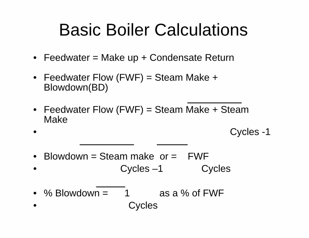
Basic Boiler Calculations• Feedwater = Make up + Condensate Return
• Feedwater Flow (FWF) = Steam Make + Blowdown(BD)
• Feedwater Flow (FWF) = Steam Make + Steam Make
• Cycles -1
• Blowdown = Steam make or = FWF• Cycles –1 Cycles
• % Blowdown = 1 as a % of FWF • Cycles

Condensate Return is also expressed as % of FWF
If Condensate Return = 60% Make up = 40%
% Condensate + % Make up = 100% = FWF
As the boiler water cycles of concentration increase then the feedwater flow and the steam make approach the same number
Basic Boiler Calculations

Calculate the feedwater composition (impurities) from make up and condensate analysis below
Make-Up Condensate FeedwaterTotal Hardness 2 0M Alkalinity 200 10TDS 350 15Silica 6 0% Condensate 50
Basic Boiler Calculations

Calculate the feedwater composition (impurities) from make up and condensate analysis below
Total HardnessM AlkalinityTDSSilica% Condensate
Make up
2200350
6
Condensate
010150
50
Feed water
1105
182.53
Basic Boiler Calculations

Boiler Water Best PractisesBoiler Water Best Practises

Boiler Water
Internal Treatment
Technology
Why is Effective Internal BoilerWater Treatment Necessary ?

Effective Internal Boiler Water Treatment
Controls
• Deposition
• Corrosion
• Carryover
and

Enhances System Reliability and Efficiency
• Avoids unscheduled shutdowns
• Helps ensure uninterrupted production
• Reduces maintenance costs
• Reduces operating costs

What Operating Costs are Associated with Boiler
Operation ?

Boiler Operating Costs
• Fuel - Gas, Oil, Coal
• Water - Influent and Effluent
• Regenerants - Salt, Acid,
Caustic
• Water Treatment

• Fuel - Gas, Oil, Coal• Water - Influent and Effluent• Regenerants - Salt, Acid, Caustic
• Water Treatment
Boiler Operating Costs

• Need to minimise all operating costsReducing boiler water blowdown giveswater, energy and chemical savings
• Need to maximise efficiency Maintain clean heat transfer surfacesHeat recovery systems
Boiler Operating Costs

Effective Internal Boiler Water Treatment
Controls
•Deposition

Boiler Water Deposit Control
• Hardness salts• Calcium• Magnesium
• Metal oxides• Iron• Copper

Comparison of Heat Transfer Surfaces With and Without Deposits
Fireside Waterside Fireside Waterside
Metal Metal Scale
Without deposits With deposits
600°F 500°F 500°F
800°Fandabove
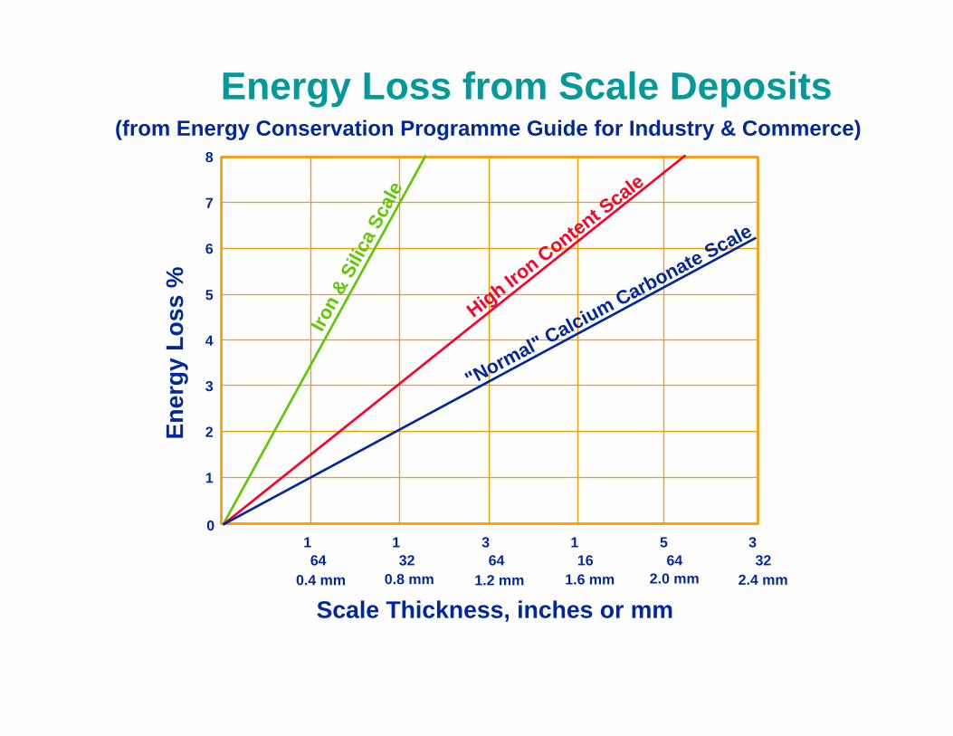
Energy Loss from Scale Deposits(from Energy Conservation Programme Guide for Industry & Commerce)
164
132
364
116
564
332
0
Scale Thickness, inches or mm
Ener
gy L
oss
%8
7
6
5
4
3
2
1
Iron
& Si
lica
Scal
e
High Iron Content S
cale
"Normal" Calcium Carbonate Scale
0.4 mm 0.8 mm 1.2 mm 1.6 mm 2.0 mm 2.4 mm

Long Term Overheating

Boiler Water Deposit Control
• Removal of impurities• Pretreatment plant
• Chemical treatment
• Controlled blowdown

Effective Internal Boiler Water Treatment
Controls
• Deposition
• Corrosion

Boiler Water Corrosion Control
• Oxygen pitting
• Caustic corrosion• Embrittlement or gouging
• Acidic attack

Oxygen Corrosion - Pitting


Caustic Gouging

Acid Corrosion
Acid Corrosion

Effective Internal Boiler Water Treatment
Controls• Deposition
• Corrosion
• Carryover

Control of Boiler Water Carryover
• Effective mechanical steam separation
• Proper control of boiler water chemistry
• Antifoam, as needed
• Avoid major contaminant ingress
• Proper boiler operating practices

What Types of Internal Boiler Water
Treatments are Available ?

Internal Treatment Programmes
General Classifications• Precipitating
• Solubilising
• Combination
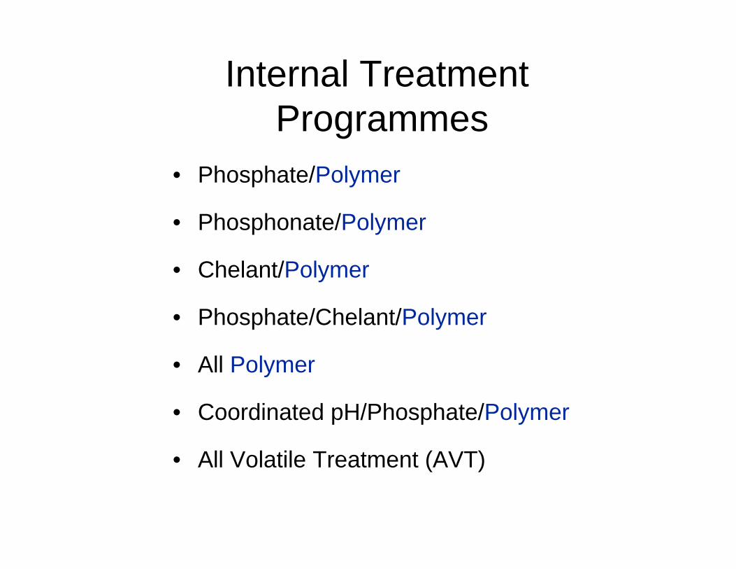
• Phosphate/Polymer
• Phosphonate/Polymer
• Chelant/Polymer
• Phosphate/Chelant/Polymer
• All Polymer
• Coordinated pH/Phosphate/Polymer
• All Volatile Treatment (AVT)
Internal Treatment Programmes

Boiler Water Polymers
are Crucial to the
Success of any
Internal Treatment Programme

How do Boiler Water Polymers Function ?

Boiler Water Polymers
The mechanisms by which boiler water polymers function are
• Complexation / Solubilisation
• Crystal modification
• Dispersion

Calcium phosphate, magnesium silicate crystals formed in boiler water without dispersant

Calcium phosphate, magnesium silicate crystals formed in boiler water in the presence of a sulphonated polymer

Variables Affecting Polymer Performance
• Functional group• carboxylated (SCP/SCCP)• sulfonated (SSP)• phosphorylated (HTP)
• Polymer backbone
• Molecular weight

CH3
O-
Polymethacrylate
X
C CH2
C=O
CH
O-
CH2
Polyacrylate
C = O
X
CH2
OH
CH
Acrylate-Acrylamide Copolymer
CH2
NH2
CH
X
C = OC = O
CH2
SO3-
CH
Sulfonated Styrene-MaleicAnhydride Copolymer
CH CH
C
X Y
C =
OO
O=
Typical Polymer Structures

O-
O-
Phosphonate
P = O
Poly (isopropenyl phosphonic acid) PIPPA
O P
C
CH3
OH
XO-
CH2
=
R
HEDP
P- O
O
C P
CH3
OH
O
O -- O
O -
= =
Polyethylene glycol allyl ether (PEGAE)
CH2 CH
C = O
O- H+
CH2 CH
CH2
O [CH2 CH2 O]m Hn
Typical Polymer Structures

Polymer Performancevs
Molecular Weight
Polymer Molecular Weight
Dep
ositi
on

Programme Selection Considerations
• Boiler pressure, design
• Pre-treatment plant type
• Feedwater quality
• Hot well, deaerator type
• Steam turbine
• Control capabilities

Chemical Factors
• Total Dissolved Solids (TDS)
• Alkalinity
• Silica
• Suspended Solids

ASME Boiler Feedwater Quality Guidelines for Modern Industrial
Water-Tube Boilers•Drum Pressure
•(kg/cm²)
•0 - 21•22 - 31•32 - 42•43 - 52•53 - 63•64 - 70•71 - 105
Iron(ppm Fe)
0.100.050.03
0.0250.020.020.01
Copper(ppm Cu)
0.050.0250.020.02
0.0150.0150.01
Hardness(ppm CaCO3)
0.300.300.200.200.100.050.0
Internal Treatment Programmes
• Phosphate/Polymer

Phosphate/Polymer Treatment
• Reactions:
• Ca + PO4 + OH Ca(OH)PO4
• Calcium Phosphate Hydroxide Hydroxyapatite
•
• Mg + SiO3 + OH Mg(OH)SiO3
• Magnesium Silica Hydroxide Serpentine

Phosphate/Polymer Treatment
Characteristics
• Hardness controlled by precipitation• Polymers used to control hardness
sludge and metal oxides• Phosphate residual used for programme
control
• Hydroxide alkalinity required (pH : 10.5 -
12)

Phosphate/Polymer Treatment
Boiler Control Parameters• Phosphate residual as PO4 depending on
hardness in the feedwater• usually associated with boiler pressure• and environmental legislation
• M alkalinity of 700 ppm as CaCO3 (25 % of TDS)
• Polymer : min 360 ppm as SP8100• Still the most used method for treating low
pressure boilers

Phosphate/Polymer Treatment
• Disadvantages
• Is a precipitation programme (some deposition is normal)
• Higher blowdown rates may be required
Advantages
• Tolerates a wide range of feedwater hardness
• Non corrosive treatment
• Suitable for low to medium pressure systems
• Easy operator control

Internal Treatment Programmes
• Phosphate/Polymer
• Phosphonate/Polymer

Phosphonate/Polymer
Characteristics
• Organic phosphor donors combined with three synergistic polymers
• Complexes hardness, iron and copper ions in BFW
• Disperses/solubilises contaminants in boiler minimising sludge formation

Phosphonate/Polymer
– 200 - 300 ppm in blowdown– (BFW hardness + tot Fe) max 1 ppm for
300 ppm in boiler– filtered tot. PO4 min 6 ppm in BD – Other :
• conductivity• SiO2• M-alk
a) Solubilising
Boiler Control Parameters

b) Precipitating
• Phosphate residual as PO4 depending on hardness in the feedwater
• M alkalinity of 700 ppm as CaCO3 (25 % of TDS)
Phosphonate/Polymer
Boiler Control Parameters

Internal Treatment Programmes
• Phosphate/Polymer
• Phosphonate/Polymer
• Chelant/Polymer

Chelant/Polymer Treatment
• Common Chelating Agents
• EDTA
• NTA

Chemical Structure of EDTA
- OOC - CH2
- OOC - CH2
N - C - C - N
H CH2 - COO -
CH2 - COO -
H
H H
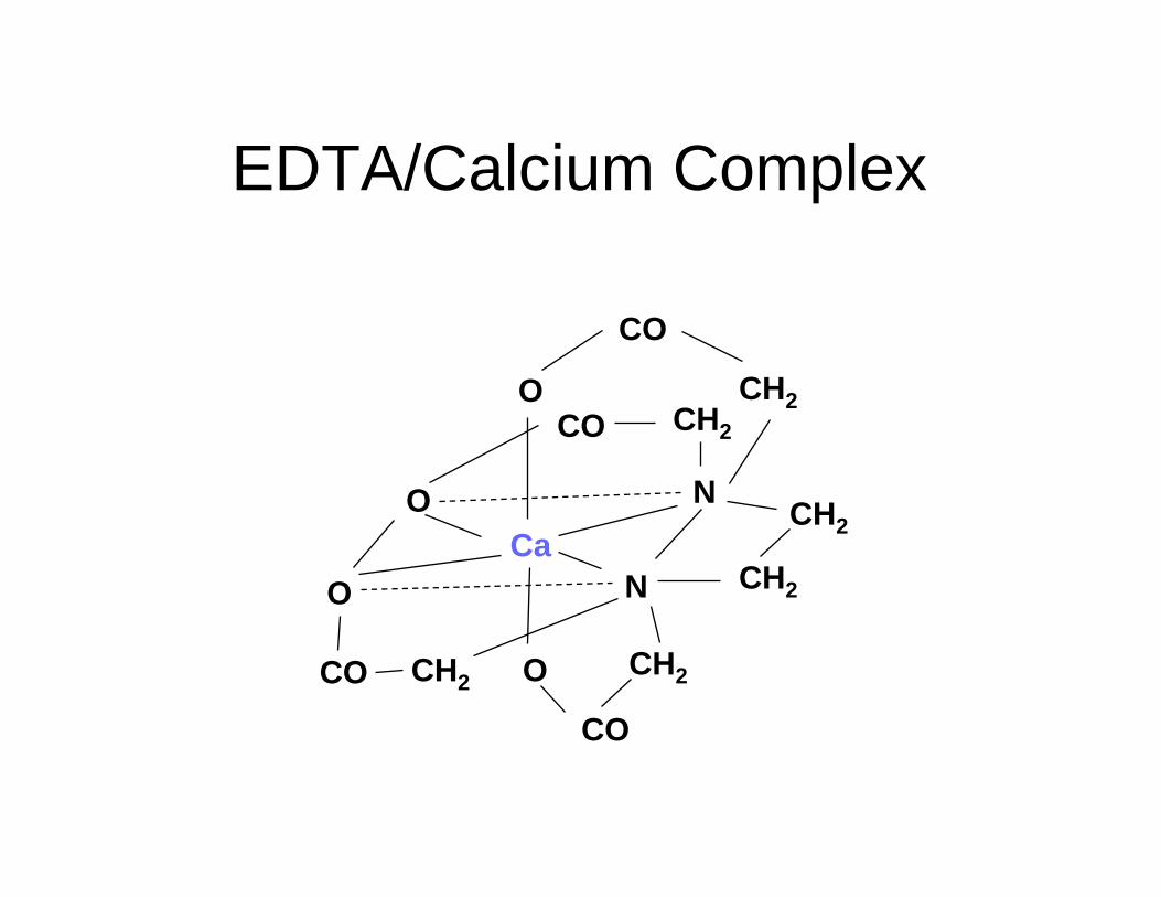
EDTA/Calcium Complex
Ca
CO
N
N CH2
CH2CH2
CH2
CH2CH2CO
CO
CO
O
O
O
O

Chelant/Polymer Treatment
Characteristics
• Are solubilising treatments
• Chelant complexes hardness and soluble iron / copper
• Polymers used to enhance metal oxide control
• Must be fed to the feedwater line

Chelant/Polymer Treatment• Disadvantages
• Requires intensive operator control
• Potentially corrosive if misapplied
Advantages
• Solubilising treatment
• Effective on hardness and soluble iron
• Allow reduced blowdown
• Increased reliability and efficiency
• Suitable for low to medium pressure systems

Internal Treatment Programmes
• Phosphate/Polymer
• Phosphonate/Polymer
• Chelant/Polymer
• Phosphate/Chelant/Polymer
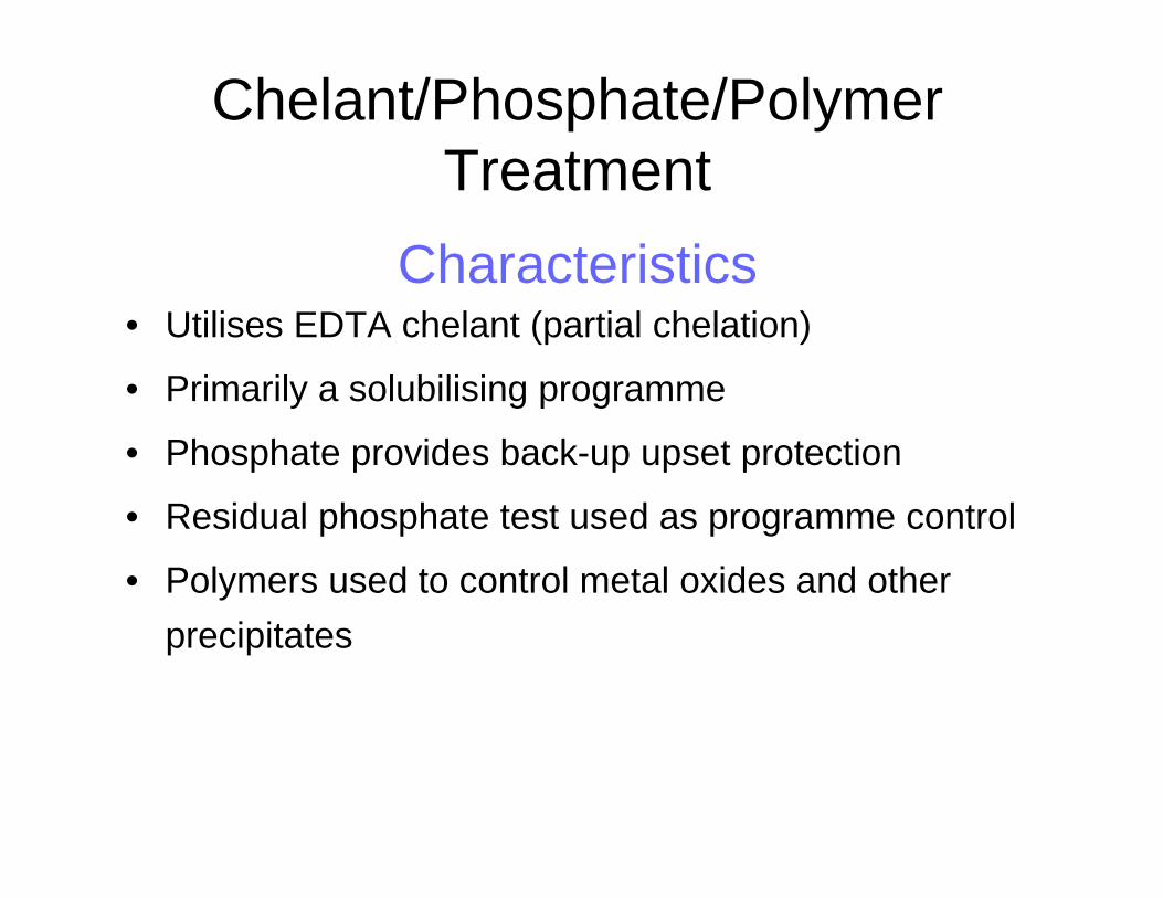
Chelant/Phosphate/Polymer Treatment
Characteristics• Utilises EDTA chelant (partial chelation)
• Primarily a solubilising programme
• Phosphate provides back-up upset protection
• Residual phosphate test used as programme control
• Polymers used to control metal oxides and other precipitates

Chelant/Phosphate/Polymer Treatment
• Disadvantages
• Some precipitation is possible
• Potentially corrosive if misapplied
Advantages
• Primarily a solubilising treatment
• Effective on hardness and iron
• May allow reduced blowdown
• Increased reliability and efficiency
• Easy and accurate control test
• Tolerates a wide range of feedwater hardness
• Suitable for low to medium pressure systems

Internal Treatment Programmes
• Phosphate/Polymer
• Chelant/Polymer
• Phosphate/Chelant/Polymer
• All Polymer

All Polymer TreatmentCharacteristics
• Certain polymers can be effective complexing agents
• Principle mechanism is complexation of soluble impurities
• Secondary mechanism is dispersion of particulates
• Fed to the boiler feedwater
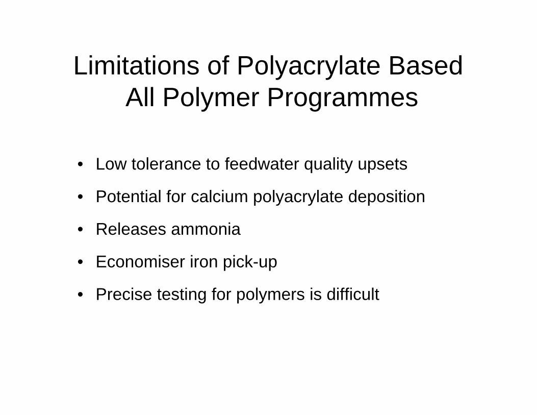
Limitations of Polyacrylate Based All Polymer Programmes
• Low tolerance to feedwater quality upsets
• Potential for calcium polyacrylate deposition
• Releases ammonia
• Economiser iron pick-up
• Precise testing for polymers is difficult

Internal Treatment Programmes
• Phosphate/Polymer
• Phosphonate/Polymer
• Chelant/Polymer
• Phosphate/Chelant/Polymer
• All Polymer/OptiSperse AP

What is OptiSperse AP ?
• A new, revolutionary programme using patented co-polymer technology
• A stand-alone all polymer / all organic boiler internal treatment programme which provides superior control over hardness and iron deposition

OptiSPerse AP Treatment vs. Traditional All Polymer
• Traditional All Polymer Programme
• Generates ammonia
• Forms calcium-polymer deposits with BFW
hardness excursions or underfeed
• Overfeed may cause foaming
• Corrosive to economiser surfaces
• Must be fed downstream of copper alloys
• OptiSperse AP Programme
• No ammonia generated
• No treatment related deposition
• No steam purity problems
• Not corrosive to preboilercircuit
• May be fed ahead of copper alloys in BFW

Research Boiler Studies Under Fouling Conditions
Test Conditions900 psig (63 kg/cm2)All-polymer ProgrammeCa/Mg/Fe present
TRADITIONAL ALL-POLYMER
OPTISPERSE AP
0 1 2 3 4 5
POLYMER/HARDNESS RATIO
DW
D

Research Boiler StudiesUnder Potential Fouling Conditions
(Equal Polymer Actives)
300 psig (21 kg/cm2) 600 psig (42 kg/cm2) 900 psig (63 kg/cm2)
Dep
osit
Wei
ght D
ensi
ty
OPTISPERSE AP Traditional All-Polymer

Internal Treatment Programmes
• Phosphate/Polymer
• Phosphonate/Polymer
• Chelant/Polymer
• Phosphate/Chelant/Polymer
• All Polymer
• Coordinated
pH/Phosphate/Polymer

Coordinated pH/Phosphate Polymer Treatment
Characteristics• Primarily for high purity/high pressure
systems
• Mainly a corrosion control programme
• Phosphate used to control pH and neutralise excess caustic
• Polymers used to control deposition

Corrosion of Mild Steel vs. pH
1 2 3 4 5 6 7 8 9 10 11 12 13 14Safe Range
Rel
ativ
e C
orro
sive
Atta
ck
8.5 pH 12.7 pH

Caustic Concentration Mechanism
Magnetite
NaOH
Steam Out
NaOH
Boiler Water in
Fe3O4 PorousDeposit
NaOH
NaOH
NaOH
NaOH

Boiler water in
steamescapes
porousdeposit
magnetite
Na+
HPO42 -
Na+
Na+
Na+
Na+
Prevention
HPO42 -
HPO42 -
HPO42 -
HPO42 -
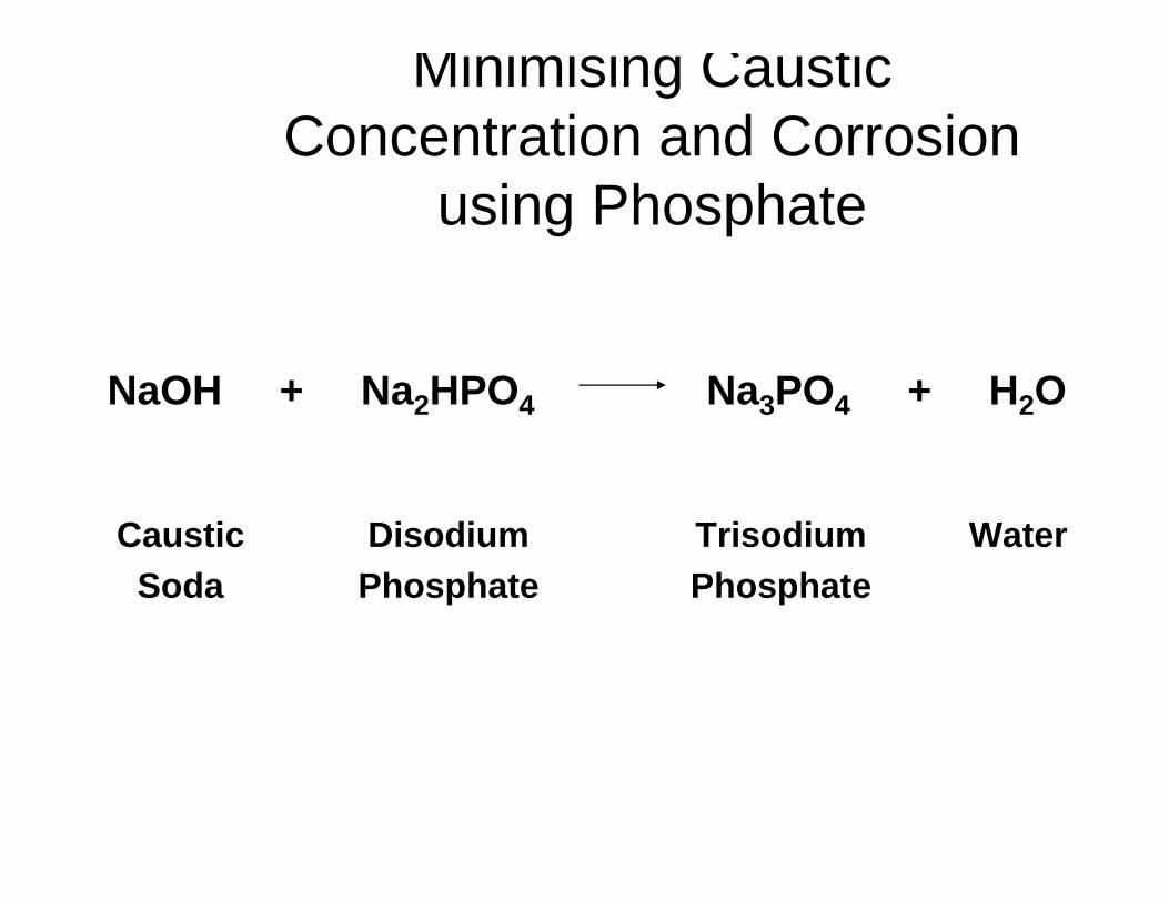
Minimising Caustic Concentration and Corrosion
using Phosphate
NaOH + Na2HPO4 Na3PO4 + H2O
CausticSoda
DisodiumPhosphate
TrisodiumPhosphate
Water

Co-ordinated Congruent Phosphate/pH Control Chart
2.6:1 Na/PO4
8.28.48.68.89.09.29.49.69.8
10.010.210.410.610.8
102 3 4 5 6 7 81 15 20 30 40 50 60Ortho-phosphate, as PO4 mg/l
"Free" CausticRegion
Maximum Boundary 3.0:1 Na/PO4Molar Ratio
Control Boundary 2.2:1 Na/PO4Molar Ratio "Captive"
AlkalinityRegion
2.7:1 Na/PO4
2.8:1 Na/PO4
pH
VectorControlDiagram
Tri-Sod
ium
Phosphate
Cau
stic
Mono-Sodium
Phosphate
BlowdownDi-SodiumPhosphate

Internal Treatment Programmes
• Phosphate/Polymer
• Phosphonate/Polymer
• Chelant/Polymer
• Phosphate/Chelant/Polymer
• All Polymer
• Coordinated pH/Phosphate/Polymer OptiSperse
HTP

Characteristics of HTP-2
• A unique new phosphorylated boiler polymer
• Particularly effective on iron
• Demonstrated clean-up ability
• Designed for high purity/high cycles systems
• Suitable for use up to 125 kg/cm²
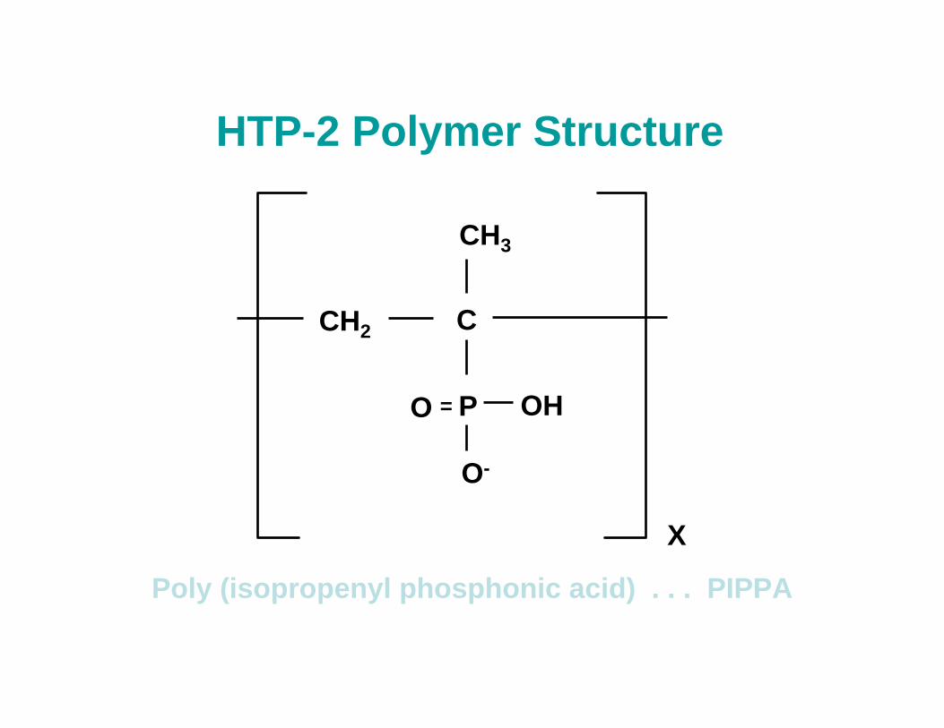
HTP-2 Polymer Structure
O P
C
CH3
OH
X
O-
CH2
=
Poly (isopropenyl phosphonic acid) . . . PIPPA

Internal Treatment Programmes
• Phosphate/Polymer - OptiSperse PO, OptiGuard MCP
• Phosphonate/Polymer - OptiSperse PQ
• Chelant/Polymer - OptiSperse CL
• Phosphate/Chelant/Polymer - OptiSperse CP
• All Polymer - OptiSperse AP, OptiGuard MCA
• Coordinated pH/Phosphate/Polymer - OptiSperse HTP
• All Volatile Treatment (AVT)