boiler and unfired pressure vessel code -...
TRANSCRIPT

DEPT. OF INDUSTRY, LABOR & HUMAN RELATIONS I
Cl^ fin,
/ Chapter Ind 41
BOILER AND UNFIRED PRESSURE VESSEL CODE
Ind 41.01 f Scope Ind 41.67 Pressure calculation forInd 41.02. De finitions furnaces and circularInd 41.03 Safety regulations fluesInd 41.04 Reporting of accidents Ind 41.68 Boiler plate thickness
and major repairs Ind 41.69 Other methods of in-Ind 41.05 jReporting'boiler and stalling safety devices
;pressure vessel locations and 'other appliancesInd 41.06 ' Identi fication of boilers Ind 41.70 Factor of safety
Ind 41. 71 StrengthInd 41.08 Cedrtificate ofecompe- Ind 41.72.
renegrthlsShearing tre
sof
tency as inspector rivetsInd 41.11 Boiler blow-down equip- Ind 41.73 Efficiency of joint
went Ind 41.74 Ligament between par-Ind 41.12 Vessels supplied through allel tube holes
pressure reducing valves Ind 41.75 Ligaments 'between di-Ind 41.13 [ Maintenance axonal tube holesInd 41.20 Periodic- inspections -re- Ind 41.76 Maximum pressure for
quired cast iron boilersInd 41.21 Vessels exempt from Ind 41.77 'Safety or relief valves__
periodic inspections required on boilersInd 41.22 Preparation for internal Ind 41.78 Safety valves for low
Inspections pressure 'steam, minia-Ind 41.23 Insurance company in- ture and power boilers
spections Ind 41.79 Water-relief valves forInd 41.24 Inspections by citiesInd 41.26 Companies or corpora_ Ind 41.80
hot water boilersThermometers for hot
tions <allowed to make water 'boilersInspections Ind 41.81 Water glass
Ind 41.26 Reporting of inspectionsInd 41.27 :Inspection report forms
Ind 41.82Ind 41.83
Gage cocksWater column piping
Ind 41.28 'Certi ficates of operation Ind 41.84 Pressure gagesInd 41.29 Condemnation Ind 41.85 Stop valves on pressureInd 41.50 A.S.M.E, code vessels Ind 41.86
discharge outletsSteam mainsInd 41.51 Wisconsin special ves-
sell Ind 41.87 Bottom blow-off or drainInd 41.52 U. S. de p artment of Ind 41.88
Ind 41.89Feed pipeCombustion regulatorstransportation - federal for boilershighway division
Ind 41.53 Non-code vessels Ind 41.90 Flanged connectionsInd 41.54 Low water fuel cut-off Ind 41.91 Washout and inspection
for hot water heating Ind 41.92openingsManholesboilers
Ind 41.60 Application Ind 41.93Ind 41.94
MaintenanceThreaded openings`allowableInd 41.61 Maximum
working pressures Ind 41.95 Boiler setting and in-Ind 41.62 Code construoted vessels Ind 41.96
sAccess and doAcccess an fi ringdInd 41.63 Pressure calculations for
shells Ind 41.97 Water tube boiler doorsInd 41.64 Pressure calculations for Ind 41.98 Low-water 'cut-off and
flat heads and flat sur- water feeder-faces Ind 41.99 Pressure relief devices
Ind 41.65 Pressure calculations for required ` for unfireddished heads pressure vessels
Ind 41.66 Dished head restrictions
History: Chapters Ind 41 and 42 as ithey existed on April 30, 1961 wererepealed and new chapters Ind 41 and 42 are created effective May 1,1961.
Register, November, 1971, No 191Boiler and Unfired Pressure Vessel Code

WISCONSIN ADMINISTRATIVE CODE
PART I
SCOPE
Ind 41.01 Scope. (1) The provisions of this code apply to boilersand unfired pressure vessels in use at places of employment and inpublic buildings.
Note. Section 101.01 (1), Wis. Stats., provides that the phrase "placeof employment" means and includes every place, whether indoors or outor underground and the premises appurtenant thereto where eithertemporarily or permanently any industry, trade or business is carriedon or where any process or operation directly or indirectly related toany industry, trade or business is carried on and where any person isdirectly or indirectly employed by another for direot or indirect gain orprofit but shall not include any place where persons are employed infa) private domestic service which does not involve the use of mechan-cal ,Rower or, (b) farming. The term 'farming" includes those activities
specified in section 102.04 (3), and also includes the transportation offarm _products, supplies or equipment directly to the farm by the oper-ator<of said farm or his employees for use thereon if such activities aredirectly or indirectly for the purpose of producing commodities formarket or as an accessory to such production.
(2) ,Vessels used for the storage and transportation of liquefiedpetroleum gas, anhydrous ammonia, and refrigerants shall be subjectonly to the provisions of this code found under Part V "New Installa-tions", Part VII "Repairs, Additions, Alterations, and Special Rules",and Part VIII "Second Hand Boilers and Second Hand Unfired Pres-sure Vessels."
(3) The provisions of this code do not apply to air eliminators,scraper traps, and similar devices on the pumping and dispensingequipment or systems used in the transportation, storage, or distribu-tion of flammable liquids.
History: Cr. Register, April, 1961, No. 64, eff. 5-1-61.
PART II
DEFINITIONSInd 41.02 Definitions. (1) A.S.M.E. BOILER AND UNFIRED PRESSURE
VESSEL coDES are those published by the American Society of Mechan-ical Engineers.
(2) ?BOILER. A closed vessel intended for use in heating water orfor the application of heat to generate steam or other vapor to beused externally to itself.
(a) Low pressure boiler. A boiler on which the safety valves are setat pressures not exceeding 15 psig.
(b) 'Miniature boiler. A boiler on which the safety valve is set atover 15 psig and that does not exceed the following limits:
16 inch inside diameter of shell;5 cubic feet gross volume;
100 psi maximum allowable working pressure.
(c) Portable boiler. An internally fired boiler primarily intended fortemporary location and whose construction and usage is obviously ofa portable nature.
(d) Power boiler. A boiler on which the safety valves are set at apressure of more than 15 psig and that exceeds the dimensions of aminiature boiler.
Register, November, 1971, No. 191Boiler and Unfired Pressure Vessel Code
DEPT. OF INDUSTRY, LABOR & HUMAN RELATIONS
(3) CERTIFICATE OF COMPETENCY. A certificate issued to a boileror pressure vessel inspector by the department of industry, laborand human relations.
(4) EXISTING INSTALLATION. Boiler and pressure vessels placedin operation or contracted for prior to January 1, 1957. (See part VI)
(5) EXTERNAL INSPECTION. One made while boiler or vessel is inoperation.
(6) FUSION WELDING. The melting together of filler metal and basemetal, or of base metal only, which results in coalescence.
(7) HOT WATER HEATING BOILER AND HOT WATER SUPPLY. A boilercompletely filled with water that furnishes hot water to be usedexternally to itself at pressures not exceeding 1.60 psig or at tempera-tures not exceeding 250 F. (A boiler exceeding either of these limitsshall be classified as a power boiler.)
(3) INSPECTOR, AUTHORIZED OR QUALIFIED. (a) Field inspector.A boiler or pressure vessel inspector who holds a valid certificateof competency.
(b) 'Shop inspector. A boiler or pressure vessel inspector who isholding the necessary commissions and employed by a city or a statewhich has adopted the A.S.M.E. boiler and pressure vessel code,or who is employed by an insurance company, and who when per-forming shop inspections in Wisconsin holds a Wisconsin certificateof competency.
(9) INTERNAL INSPECTION. One made when the boiler or pressurevessel is shut down and hndholes and manholes or other inspectionopenings are opened or removed for inspection of the interior asrequired by the inspector.
(10) MAJOR REPAIR. A riveted or welded repair to a boiler drum,pressure vessel drum, or boiler water leg.
(11) NEW INSTALLATION, BOILER OR PRESSURE VESSEL, One placedin operation or contracted for after January 1, 1957.
(12) NON-STANDARD BOILER OR NON-STANDARD PRESSURE VESSEL.One not bearing a valid Wisconsin stamping, nor the A.S.M.E.stamping, nor the National Board stamping, nor the U. S. Depart-ment of Transportation stamping, nor the stamping of the A.P.I.-A.S.M.E., nor any stamping authorized by other applicable codes.
(13) OWNER OR USER. Any person, firm, or corporation owningor operating ,a boiler or pressure vessel.
(14) SECOND HAND VESSEL. A boiler or pressure vessel when bothlocation and =ownership have been changed subsequent to the origi-nal installation.
(15) PRESSURE VESSEL. A 'vessel that obtains its pressure froman external source or from an indirect application of heat.
(16) CONDEMNED. A boiler or pressure vessel declared to be un-safe and has an applied stamping designating its condemnation.
Note: For further explanation of definitions see the current edition of theA,S.M.E. 'Code—Section VIII—Scope.
History: Cr. Register, April, 1961 No 64, eff. 5- 1-61; am. (2) (b), (7),(10), Register, January, 1966, No. 121, eff. 2-1-66; am, (3), (4), (8) (a)and (b), (9), (10), (11), (12), (13), (14), (15), and cr . (16), Register,October, 1970, No. 178, eff. 11-1-70.
Register, November, 1971, No 191Boiler and Unfired Pressure Vessel Code
WISCONSIN ADMINISTRATIVE CODE
PART III
GENERAL RULES
Ind 41.03 Safety regulations. (1) No boiler or pressure vessel shallbe operated at a pressure in excess of the maximum operatingpressure stated on its current certificate of operation.
(2) No unauthorized person shall remove or tamper with anyconnected safety device nor shall any person adjust a connectedsafety valve to a greater relieving pressure than that allowed forthe vessel as stated on its current certificate of operation.
(3) Boiler and pressure vessels shall be so installed that therewill be sufficient room between the vessel and any ceiling, wall, par-tition, or floor to facilitate the connection and operation of valves,pipes, and other appurtenances and shall be installed in a mannerthat will not block any inspection opening.
History: Cr. Register, April, 1961, No. 64, eff. 5-1-61; a.m. (3), Register,January, 1966, No. 121, eff. 2-1--66; am., Register, February, 1971, No. 182,eff. 3-1-71.
Ind 41.04 Reporting accidents and major repairs. (1) Whenever aboiler or pressure vessel fails and causes injury to any person, theowner or user shall report the facts involved to the Department ofIndustry, Labor and Human Relations within the following 24 hours.The owner or user shall not remove or disturb the vessel or any ofits parts nor permit any such removal or disturbance prior to receiv-ing authorization from the Department of Industry, Labor andHuman Relations, except for the purpose of saving human life orfurther property damage.
(2) ; The owner shall report any major repairs of a boiler or pres-sure vessel as provided in Part VII "Repairs, Additions, Alterationsand Special Rules."
History: Cr. Register, April, 1961, No. 64, eff. 5-1-61; am., Register,February, 1971, No. 182, eff. 3-1-71.
Ind 41.05 Reporting boiler and pressure vessel locations. (1) Theowner or user of any boiler or pressure vessel shall report the loca-tion of suc vessels unless either of the following conditions are met:
(a) The vessels are exempt from periodic inspections. See sectionInd 41.2V by the Department of Industry, Labor and HumanRelations.
(b) The vessels are subjected to periodic inspection by the De-partment of Industry, Labor and Human Relations, a city, an insur-ance company, or a company authorized to make its own inspections.
History: Cr. Register, April, 1961, No. 64, eff. 5-1-61; am. Register,February, 1971, No. 182, eff. 3-1-71.
Ind 41.06 Identification of boilers and pressure vessels. (1) Theowner or user of a boiler or pressure vessel shall number each vesselin some permanent manlier and in an accessible location.
(2) Boilers a d pressure vessels subject to periodic inspections(see Ind 41.20) shall be identified by a registration number suppliedby the Department of Industry, Labor and Human Relations. Theregistration number shall be affixed by an authorized inspector. Thestate tag 'shall be attached to the vessel at a location which can beeasily, viewed.
History: Cr. Register, April, 1961, No. 64, eff. 5-1-61; r. and reer.Register, February, 1971, No. 182, eff. 3-1-71.
Register, November, 1971, No. 191Boiler and Unfired Pressure Vessel Code

DEPT. OF INDUSTRY, LABOR & HUMAN RELATIONS 5
Ind 41.08 Certificate of competency as inspector. (1) CERTIFICATEREQUIRED. An inspection report covering a boiler or pressure vesselmay be recognized and accepted only when the inspector holds a validcertificate of competency issued by the Department of Industry,Labor and Human Relations.
(2) ELIGIBILITY. (a) The applicant for a certificate of competencyas a boiler or pressure vessel inspector shall be an employe of thestate, a municipality, an insurance company, or a corporation orcompany authorized to make its own inspections.
(b) The applicant shall be at least 25 years of age. He shall havehad at least3 years of experience in one or more of the followingendeavors: construction, repairing, inspecting, or operating engineerin charge of high pressure steam boilers or pressure vessels.
(c) A degree in mechanical engineering may be accepted as theequivalent of 2 years practical experience." (d) The appplicant's employer shall certify that applicant's state-ment of experience is correct.
(3) APPLICATIONS AND RENEWALS. (a) Pees for examination andreciprocal certificates of competency shall be submitted with appli-cations nd in the amount specified in Wis. Adm. Code chapterInd 69
(b) Renewal fees shall be submitted with the request for renewaland in the amount specified in chapter Ind 69.
(c) A request for renewal shall be filed with the Department ofIndustry, Labor and Human Relations on or before January 1 ofthe calendar year for which the certificate is to be valid.
(d) Applications for examinations and applications for renewalsby employes of the state and employes of the city of Milwaukeerequire no fee.
(4) EXAMINATIONS. (a) Certificates of competency for a boileror pressure vessel inspector may be issued by the Department ofIndustry, Labor and Human Relations to eligible applicants passingthe examinations prescribed by and conducted by the department.
(b) Holders of certificates, who do not apply for renewal in any3 year period may be required to pass a scheduled examination.
(5) ANNULMENTS AND REVOCATIONS. (a) A certificate becomesinvalid when the holder terminates his employment with the employerof record at the time of issue. A renewal may be obtained underthe provisions of this section provided applicant meets eligibilityrequirements.
(b) A certificate may be annulled or revoked when incompetencyor negligence is determined after investigation.
(6) RECIPROCAL COMMISSIONS. (a) A reciprocal certificate of com-petency may be granted by the Department of Industry, Labor andHuman Relations to a boiler or pressure vessel inspector under thefollowing conditions:
1. The inspector shall be employed by a boiler insurance companylicensed to do business in Wisconsin. The boiler insurance companyshall make the application for a reciprocal commission to the Depart-ment of Industry, Labor and Human Relations.
2. The inspector shall hold a commission issued by the NationalBoard of Boiler and Pressure Vessel Inspectors or a certificate of
Register, November, 1971, No 191Boiler and Unfired Pressure Vessel Code
WISCONSIN ADMINISTRATIVE CODE
competency from a city or state which has adopted the A.S.M.E.Boiler and Pressure Vessel Code and which holds a written examina-tion similar to that required by Wisconsin.
3. The inspector shall appear before an examining board ap-pointed by the Department of Industry, Labor and Human Relationsto review his qualifications as an inspector
History: Cr.Register, April, 1961, No. 64, eff. 5-1-61; r. and recr.Register, February, 1971, No. 182, eff. 3-1-71.
Ind 41.11 Boiler blow-down equipment. (1) The blow-down from aboiler or boilers that enters a sewer system or blow-down which isconsidered a hazard to life or property shall pass through some formof blow-off equipment that will reduce pressure and temperature asrequired hereinafter.
(2) The temperature of the water leaving the blow-off equipmentshall not exceed 140 F.
(3) The pressure of the blow-down leaving any type of blow-offequipment shall not exceed 5 psi.
(4) The blow-off piping and fittings betwecc^ the boiler ,id the blow-off tank shall comply with sections Ind 41.50^and Ind 41.51 of this code. f
(5) The tanl shall be designed in accordance with sections Ind 41.504and Ind 41.5V of this code for a working pressure of at least one-fourth the lnaximum working pressure of the boiler to which it isconnected.
(6) All blow-off equipment, except centrifugal blow-down separa-tors, shall be fitted with openings to facilitate cleaning and inspection.
Note: Blow-off equipment designed in accordance with the boiler blow-offequipment code issued by the National Board of Boiler and Pressure VesselInspectors, 1.968 edition, will meet the re quirements of this section. Othermethods of designing blow-off equipment may be used if approved by theDepartment of Industry, Labor and human Relations.
<(Available for inspection at the 'office of the Department of Industry,Labor and Human Relations and the secretary of state's office and the officeof the 'revisor of statutes or may be procured for personal use from theNational Board of Boiler and Pressure Vessel Inspectors, 1155 North HighStreet, Columbus, Ohio.)
History: Cr. Register, April, 1961, No. 64, eff. 5-1-61.
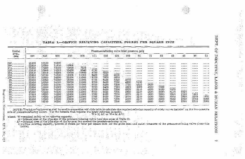
Ind '41.12 Vessels supplied through pressure reducing valves. (1)The following formula 'shall be used for determining the sizes ofsafety and relief valves on pressure vessels such as pressure cookers,indirect hot water heaters, equipment in heating systems, etc., whichare supplied through pressure reducing valves from boilers carryinga higher steam pressure. Where a pressure reducing valve is sup-plied by a boiler, the capacity of the safety valve or valves on thelow pressure side of the system need not exceed the capacity of theboiler.RVC= % X OC X VSPAWhere RVC = re lief valve capacity, lbs. of steam per hour.OC' orifice capacity, lbs. of steam per hour per sq. in. (See Table 1.)VSPA=valve size pipe area, sq. in. (See Table 2.)
Register, November, 1971, No. 191Boiler and Unfired Pressure Vessel Code
t7hrd
HO
zr7ciMH
ti
7O
dl^°
z
HOz
TABLE 1.—ORIFICE RELIEVING CAPACI'T'IES, POUNDS PER SQUARE INCH
outletpres., —psig 400 350 300 250 200 175 150 125 : 100 85 75 60 50 40 30 25
250-------- 21000 17100 10800 -- ----- ---- ---- ---- ---- ---- --- ---- ---200_________ 21350 18250 15350 10900 _____ ---_ ____ -___ -___ ____ ___- ___- __-_ -___ -___175 --------- 21350 18250 16000 12600 7250 ___- - __-_ --_ _--_ --__ -___ ____150 --------- 21350 18250 16200 13400 9540 6750 -_- __-_ __-- -__ _-_- ---_ ---_ -___ ____ ____125 --------- 21350 18250 16200 13600 10800 8780 6220 ' ---- _-__ -__ __-_ ____ _-__ -___ ___-110 --------- 21350 18250 16200 13600 11000 9460 7420 4550 _-__ ___ ____ ____ ____ ____ __ _ ____
100 --------- 21350 18250 16200 13600 11000 9760 7970 5630 -___ ___ __-_ ___ ____ ___ ____ __85 --------- 21350 18250 16200 13600 11000 9760 8480 6640 4070 ___ _-__ ___ ____ ____ __-_ __ _75 --------- 21350 18250 16200 13600 11000 9760 8480 7050 4980 3150 __- -___ -_ ----60--------- 21350 18250 16200 13600 11000 9760 8480 '7200 5750 4540 3520 --_ _-__ -___ ----50--------- 21350 18250 16200 13600 11000 9760 8480 7200 5920 5000 4230 2680 --__ ----40 --------- 21350 18250 16200 13600 11000 9760 8480 7200 5920 5140 4630 3480 2470 ____ ____30 --------- 21350 18250 16200 13600 11000 9760 3480 7200 5920 5140 4630 3860 3140 2210 __-- _-__25 --------- 21350 18250 16200 13600 11000 9760 8480 7200 5920 5140 4630 3860 3340 2580 1485 -__-
m 15__-______ -21350 18250 :.16200 :13600 11000 9760 :8480 7200 5920 5140 4630 3860 3340 2830 2320 1800
10 --------- "21350 18250 16200 13600 11000 -9760 8480 7200 5920 5140 4630 3860 3340 2830 2320 20605 --------- 21350 ;c18250 16200 13600 11000 : 9760 8480 7200 5920 5140 4630 3860 3340 2830 2320 2060
<
NOTE: The following formulas shall be used in connection with this table to calculate the required relieving capacity of safety valves installed on the low-pressureside of pressure-reducing valves. Use the formula that re quires the larger relieving capacity.
W=%AC orW=MA'Cwhere: W =required safety valve relieving capacity.
A= internal area of the pipe size of the pressure-reducing valve (use pipe areas of Table 2).~ Ai =Internal area of the pipe size of the by-pass line around the pressure-reducing valve.
C = orifice relieving capacity, pounds of e. m per hour per square inch for the given inlet and outlet pressures of the pressure-reducing valve (from thisTable).
z,o
H
Pressure-reducing valve inlet pressure, psig

WISCONSIN ADMINISTRATIVE CODE
TABLE 2.-INTERNAL PIPE AREA
STANDARD
Nominal pipe size, inches Actual internal Approx. in- Approx. internal
diameter, ternal diameter, area, square
inches inches inches
Ys----------------------------- 0.675 0.49 0.19
Y2 ----------------------------- 0.840 0.62 0.30
Y4 ----------------------------- 1.050 0.82 0.53
1 ----------------------------- 1.315 1.05 0.86
1%'^---------------- ----------- 1.660 1.38 1.50
lye_____________________________ 1.900 1.61 2.04
2 -----------------------------
2.375 2.07 3.36
2 Y2 ----------------------------- 2.875 2.47 4.783 - ------ ------_______- _ _____ __ 3.5 3.07 7.39
3 Y2 ----------------------------- 4.0 3.55 9.894
-----------------------------4.5 4.03 12.73
5 ----------------------------- 5.563 5.05 19.99
6 -----------------------------
6.625 6.07 28.89
8 -----------------------------
8.626 8.07 51.15
10 ----------------------------- 10.750 10.19 81.55
12 _____________________________ 12.750 12.09 114.80
Note: In applying these rules, the area of the pipe is always based uponstandard weight pipe and the inlet size of the pressure-reducing valve.
(a) The following formula shall be used to determine the steamflow rate through the bypass when pressure reducing valves are ar-ranged with a valved bypass which also acts as a potential steamsource hazard in case the bypass is left open.
RVC - 1/2 X OC X BPA.Where RVC = relief valve capacity, lbs. of steam per hour.OC ;_ orifice capacity, lbs, of steam per hour per square inch. (See
Table 1.)BPA - bypass pipe area, sq. inch. (See Table 2.)(b) The larger of the relief valve capacities calculated by the formu-
las in subsections Ind 41.12 (1) "/and (1) (a) shall be used for select-
ing the relief valve for the vessel.Note: Example. Suppose a high pressure boiler operating at 125 psi
distributes steam to a series of 40 psi ASME constructed retorts througha 1 1/2 inch size pressure reducing valve provided with a glove-valved1 inch bypass. Determine the proper ASME relief valve protection forthe retorts. Utilizing data in tables and the fi rst of the 2 formulas above:
W '/a X 7200 iX 2.04 = 4896 lbs. steam per hour.Checking the bypass steam flow according to the second formula gives:W = 1/2 X 7200 X 0.86 3100 lbs, steam per hour.The potential steam flow through the pressure reducing valve is 4896
lbs. per hour rated capacity or4896 X 1000 or 4,896,000 BTU per hour.
History: 'Cr. Register, April, 1961, No. 64, eff. 5-1-61; am. Register,January, 1966, No. 121,' eff. ̀2-1-66; r. and veer. (1) and 'Table 1, Register,February, 1971, 'No. 182, eff. 3-1-71; r. (1) second "Note" following Table2 including referenced formulas that follow this note and cr. (1) (a)and (b), Register, May, 1971, No. 185, eff. 6-1-71.
Ind 41.13 Maintenance. (1) All boilers shall be installed and main-tained in such a manner as to prevent excessive corrosion and deter-ioration.
(2) The inspector shall note conditions during internal inspection,Register, November, 1971, No. 191Boiler and Un fl red Pressure Vessel Code

DEPT. OF INDUSTRY, LABOR & HUMAN RELATIONS 9
external inspection, or hydrostatic pressure test and shall order suchchanges or repairs as will place the boiler in a safe working condition.
Note: Section VII, A.S.M.E. Boiler and Pressure Vessel Code "Recom-mended Rules for 'Care of Boilers" is an excellent guide for 'boiler ownersand operators.
History: Cr. Register, February, 1971, No. 182, eff. 3-1-71.
PART IV
INSPECTIONS
Ind 41.20 Inspections. (1) ALL INSPECTIONS. The authorized inspec-tors of the 'department, upon presenting appropriate credentials tothe owner, operator, or agent in charge, are authorized
(a) To enter without delay and at reasonable times any factory,plant, establishment, construction site, or other area, workplace orenvironment where work, is performed by an employee of an employer;and
(b) To inspect and investigate during regular working hours andat other reasonable times, and within reasonable limits and in areasonable manner, any such place of employment and all pertinentconditions, structures, machines, apparatus, devices, equipment, andmaterials therein, and to question_ privately any such employer, owner,operator, agent or employee.
(2) CONTACTING REPRESENTATIVE. The inspector before -making hisinspection shall contact a representative of the employer, and a repre-sentative authorized by his employees who shall be given an oppor-tunity to accompany the inspector during the physical inspection ofany workplace under subsection (1),/for the purpose of aiding suchinspection.
(a) Where there is no authorized employee representative, theinspector shall consult with a reasonable number of employees con-cerning matters of health and safety in the workplace.
Note: The department policy is not to give advance notice, but inthe scheduling and in the act of inspecting it may not always be possi-ble to avoid advance notice or to obtain accompaniment` as, for example,inside boilers or in precarious locations of elevator installations, butotherwise these rules will be 'diligently observed.
(3) INSPECTION Or BOILERS. Except as regulated in section Ind41.21, boilers sliall be subjected to either a regular internal or ex-ternal inspection at least once every 12 months by a qualified inspector.
(4) INSPECTION of PRESSURE VESSELS. Except as regulated in sec-tion Ind 41.21, pressure 'vessels shall be subjected to a, regular' in-ternal or external inspection at least once every 24 months by aqualified inspector,
(5) WHEN INTERNAL INSPECTION IS NOT POSSIBLE. Where an in-ternal inspection is not possible because of the construction of theboiler, an external inspection will, be acceptable.
(6) EXTENSION OF PERIOD BETWEEN INSPECTIONS. If operating con-ditions require, longer periods between inspections of boilers maybe approved by the department of industry, labor and human re-lations upon a written request for an extension.
History: Cr. Register, April, 1961, No. 64, eff. 5-1-61; am. (2), (3),(4), Register, October, 1970, No. 178, eff. 11-1-70; renum. (1), (2), (3),(4) to be (3), (4), (5) and (6) and cr. (1) and (2), Register, April, 1973,No. 208, eff. 5-1-73.
Register, April, 1973,' No. `208Boiler and Unfired Pressure Vessel Code

10 WISCONSIN ADMINISTRATIVE CODE
Ind 41.21 Vessels exempt from periodic inspections. (1) The follow-ing,boilers and pressure vessels will not be subject to periodic inspec-tion, but in individual cases any such vessel will be subject to inspec-tion,by or on order of the department upon complaint of any personor upon initiative of the department when there is reasonable causeto suspect that the construction, installation, maintenance or operationof the vessel is not in keeping with the general purpose and intent ofthis code:
(a) Boilers or pressure vessels which receive regular inspections byUnited States government inspectors.
(b) Steam boilers or pressure vessels having an internal or externaloperating pressure not exceeding 15 psi with no limitations to size.Hot water boilers and their expansion tanks having an internal oper-ating pressure not exceeding 30 psi with no limitations to size.
(c) Boilers used exclusively for agricultural purposes.(d) Miniature boilers.(e) Pressure vessels having an inside diameter not exceeding ,6
inches with no limitation to pressure,(f) Pressure vessels having a volume of less than 5 cubic feet and
an operating pressure of less than 250 psi.(g) Pressure vessels with a volume of less than 1% cubic feet with
no ' limit on pressure.(h) Pressure vessels which are used in accordance with the regula-
tions of the U.S. Department of Transportation.(i) Air receivers having a volume not to exceed 12 cubic feet and an
operating pressure of less than 225 psi.(j) Hot water supply boilers and hot water storage tanks.(k) Vessels used for the storage or processing of cold water includ-
ing those with air cushions.History: Cr. Register, April, 1961, No. 64, eff. 5-1-61; r. and recr,
Register, February, 1971, No. 182,'eff. 3-1-71.
` Ind 41.22 !Preparation for internal inspection. The owner or userof a boiler or a pressure vessel subject to inspection shall prepare thevessel for internal inspection after due notice from the inspector. Toprepare a vessel for an internal inspection all manhole plates, allwash-out plugs, and a sufficient number of handhole plates to permita satisfactory inspection shall be removed. The shell and heads shallbe thoroughly cleaned and exposed when so requested. Each steamboiler shall be thoroughly drained of water and all fire side surfacescleaned before an internal inspection is made.
History: Cr. Register, :April, 1961, No. 64,'eff, 5-1-61; r. and recr.Register, February, 1971, No. 182, efP. 3-1-71.
Ind 41.23 Insurance company inspections. (1) Periodic inspectionsof boilers and pressure vessels by insurance companies may be ac-cepted by the Department' of Industry, Labor and Human Relationsunder the following conditions:
(a) The boiler and pressure vessel inspectors employed by theinsurance company shall hold certificates of 'competency issued by theDepartment of Industry, Labor and Human Relations.
(b) The insurance company shall report inspections of <boilers andpressure vessels to the Department of Industry, Labor and HumanRelations as required in section Ind 41.26.
(c) The inspection procedures used by the insurance company shallconform to the regulations of this code.
Register, April, 1973, No, 208Boiler and Unfired Pressure Vessel Code

DEPT. OF INDUSTRY, LABOR & HUMAN RELATIONS 10a
(d) The insurance company shall report to the Department ofIndustry, Labor and Human Relations within 30 days when insurancecoverage is started or discontinued on a boiler or pressure vessel. Thereason for discontinuing the coverage shall be given on the report.
History: Cr. Register, April, 1961, No. 64, eff. 5-1-61; r, and recr.Register, February, 1971, No. 182, eff. 3-1-71.
Ind 41.24 Inspections by cities. (1) Periodic inspections of boilerand pressure vessels by cities of the first class may be accepted bythe Department of Industry, Labor and Human Relations under thefollowing conditions:
(a) The boiler and pressure vessel inspectors employed by the cityshall hold certificates of competency issued by the Department ofIndustry, Labor and Human Relations.
(b) The city shall keep a record of such periodic inspections.(c) The inspection procedures used by the city shall conform to the
regulations of this code.History: Cr. Register, April, 1961, No. 64, eff. 5-1-61; r. and recr.
Register, February, 1971, No. 182, eff. 3-1-71.
Ind 41.25 Companies or corporations allowed to make inspections.(1) Periodic inspections by companies or corporations of boilers orpressure vessels which they own or operate may be accepted by the
Register, April, 1973, No. 208Boiler and Unfired Pressure Vessel Code

DEPT. OF INDUSTRY, LABOR & HUMAN RELATIONS 11
Department of Industry, Labor and Human Relations under the fol-lowing conditions:
(a) The boiler and pressure vessel inspectors employed by the com-pany or corporation shall hold certificates of competency issued bythe Department of Industry, Labor and Human Relations.
(b) The company or corporation shall report inspections of boilersand pressure vessels to the Department of Industry, Labor and HulnanRelations as required in section Ind 41.26.x,
(c) The inspection procedures used by the company or corporationshall conform to the regulations of this code.
History: Cr. Register, April, 1961, No. 64, eff. 5-1-61; r, and recr.Register, February, 1971, No. 182, eff. 3-1-71.
Ind 41.26 Reporting of inspections. (1) Reports of periodic internalor external inspections of boilers and pressure vessels shall be sentto the Department of Industry, Labor and Human Relations within 30days from the date of the inspection.
(2) External inspections shall be reported only whbn^either of thefollowing conditions is found:
(a) An internal inspection is not possible because of the construc-tion of the vessel. In such cases the first inspection shall be ;reportedto the commission in the same manner as an internal inspection. Thereport shall be marked "external' and the reason for malting anexternal inspection instead of an internal shall be given.
(b) When violations of this code or unsafe conditions involving thesafety of the vessel are found. This report shall be made on A.S.M.E.Form P-6 and 'shall 'explain the violation or unsafe condition witreferences to code section numbers. A copy of the recommendationsto the owner or user of the vessel shall accompany the report to thecommission.
History: Cr. Register, April, 1961, No. 64, eff, 5-1-61; am, (1), Register,February, 1971, No. 182, eff. 3-1-71.
Ind 41.27 Inspection report forms. (1) An internal or external boilernspect'̂oon that conforms to periodic inspection requirements (Ind
41.20)Vshall be reported to the Department of Industry, Labor andHuman Relations on inspection form SB 210 or National Board ofBoiler and Pressure Vessel Inspectors standard form.
(2) A pressure vessel iuspecti.n that conforms to periodic inspec-tion requirements (Ind 41.20)all be reported to the Departmentof Industry, Labor and Human Relations on inspection form SB 209or National Board of Boiler and Pressure Vessel Inspectors standardform.
(a) Multiple Vessels on a Single Report. A group of pressure vesselsof the same design and use that are interconnected or are operatedso as to form a unit, machine, or apparatus may be included in asingle report. The report shall contain the number, description, anduse of the vessel and shall be reported to the Department of Industry,Labor and Human Relations on inspection form SB 209 or NationalBoard of Boiler and Pressure Vessel Inspectors standard forma
Register, November, 1971, No. 191Boiler and Unfired Pressure Vessel Code
12 WISCONSIN ADMINISTRATIVE CODE
(3) The inspection report shall be legible and complete as possible.A manufacturer's data report of boiler or pressure vessel shall beavailable to inspector for first inspection.
History: Cr. Register, April, 1961, No. 64, eff, 5-1-61; r. and recr.Register, February, 1971, No. 182, eff. 3-1-71.
Ind 41.28 Certificates of operation. (1) After each periodic internalor external inspection a certificate of operation shall be issued tothe owner or user of the boiler or pressure vessel by the depart-ment of industry, labor and human relations or by the city author-ized by that agency.
(2) The certificate of operation shall give the maximum operatingpressure as determined using the regulations of the code.
(3) The certificate of operation shall be valid until the next re-quired periodic inspection.
(4) The certificate of operation shall be kept on file on the prem-ises by the owner or user of the boiler or pressure vessel and shallbe available when called for by a deputy of the department of in-dustry, labor and human relations.
NOTE: A fee in the amount set in chapter Ind 69, Fee Schedule,shall be paid to the Department of Industry, Labor and Human Re-lations for all Certificates of Operation.
History: Cr. Register, April, 1961, No. 64 eff. 5-1-61; am. (1), (4) and(5), Register, January, 1966, No. 121, eff. 2-1-66; am. (1), (2), (3) and(4) and r. (5), Register, October, 1970, No. 178, eff. 11-1-70.
Ind 41.29 Condemnation. (1) The condemnation of a boiler or pres-sure vessel shall be a function of the department of industry, laborand human relations only. Any boiler or pressure vessel declaredby an authorized inspector to be unsafe and beyond repair shall bereferred to the department of industry, labor and human relationsfor condemnation proceedings.
(2) Any boiler or pressure vessel confirmed by the departmentof industry, labor and human relations to be unsafe for furtheruse shall be stamped as follows:
"CONDEMNED"
"Arrowhead Stamp x Wisconsin x Arrowhead Stamp"
Letters shall be at least %" high and arrowheads shall be %" wide.(3) , It shall be unlawful for any person, firm, partnership or
corporation to use, operate, or offer for sale for operation withinthe state any condemned boiler or pressure vessel.
History: Cr. Register, October, 1970, No. 178, eff. 11-1-70,
PART V
NEW INSTALLATIONS
ORIGINAL CONSTRUCTION
Ind 41.50 A.S.M.E, code ves els. (1) E cept as regulated in Wis.Adm. Code sections Ind 41.51; Ind 41 ;52; and Ind 41.53, boilers andpressure vessels installed after the effective date of this section, shallRegister, November, 1971, No. 191Boiler and Unfired Pressure Vessel Code

DEPT. OF INDUSTRY, LABOR & HUMAN RELATIONS 13
be constructed and installed in accordance with the following sectionsof the A.S.M.E. Boiler and Pressure Vessel Code:
As Amended bySummer and
Winter Addenda(a) Section I Power Boilers________________________ 1968 Edition 1968 and 1969(b) Section II Material Specifications________________(c) Section III Nuclear Vessels______________________(d) Section IV Low Pressure Heating Boilers__________(e) Section VIII Pressure Vessels—Div. 1______________(f) Section VIII Pressure Vessels—Div. 2______________(g) Section IX Welding qualifications________________(h) Nuclear Power Piping (U.S.A.S. B31.7) ----------------- 1969 Edition
Note 1. The department of industry, labor and human relations willrecognize the applicable "case interpretations" of A.S.M.E. boiler andpressure `vessel `code published by A.S.M.E. as being acceptable.
Note 2. 'Copies of the above publication are available for inspectionat the office of the department of industry, labor and human relations,secretary of state's office, and the office of the revisor of statutes, orthey may be 'procured for personal use from the American Society ofMechanical Engineers, United Engineering Center, 345 East 47th ,Street,New York, New York 10017.
History: Cr. Register, April, 1961, No. 64, eff. 5-1-61; r. and recr. Regis-ter, December, 1962, No. 84, eff. 1-1-63; am. Register, August, 1964, No.104, 'eff. 9-1-64; 'am. Register, January, 1966, No. 121, eft. 2-1-66; am.Register, March, 1966, No. 123, eff, 4-1-66; r. and recr., Register, Novem-ber," 1970, No, 179, eff. 12-1-70; am. (1) intro, par., Register, March, 1971.No. '183, eff. 4-1-71.
Ind 41.51 Wisconsin special vessels. (1) Where it is not possible orpractical to construct a boiler or pressure vessel in st ict compliancewith the A.S.M.E. codes listed in section Ind 41.50,'Alie Departmentof Industry, Labor and Human Relations may grant a modification tothe owner or user to permit the installation of the vessel as a Wiscon-sin special within the State of Wisconsin under the following'condi-tions:
(a) When the method of designing or constructing the vessel is notcovered by the 9.S.M.E, codes, the department may approve theinstallation of the vessel if adequate proof of comparable safety ofthe design or construction is shown.
1. Complete plans, calculations, and specifications in duplicate shallbe submitted to and approved by the department before the vessel isinstalled.
(b) When the vessel is to be built by an owner for his own use, thedepartment may waive the stamping required by the A.S.M.E, codeslisted in section Ind 41.50.
1. Complete plans, calculations, and specifications in duplicate shallbe submitted to and approved by the department before th6vessel -is'installed.
(c) Whence small number of vessels is to be built by a manufacturer,the department may waive the stamping required by the A.S.M.E.codes listed in section Ind 41.50.V'
1. Complete plans, calculations and specifications in duplicate shallbe submitted to and approved by the department before the vessel isinstalled.
(2) The provisions of this section shall not apply to Wisconsinspecial vessels accepted by the Department of Industry, Labor andHuman Relations before the effective date of this section.
History: Cr. Register, April, 1961, No. 64, eff. 5-1-61; r. and recr.Register, February, 1971, No. 182, eff. 3-1-71.
Register, November, 1971, No 191Boiler and Unfired Pressure Vessel Code

14 WISCONSIN ADMINISTRATIVE CODE
Ind 41.52 U.S. Department of Transportation—Federal highway Di-vision. Pressure vessels carrying the stamping of the D.O.T. will beconsidered Arnparable to a vessel meeting the requirements of sectionInd 41.50. '̀r hen such vessels are used in the State of Wisconsin, itshall be the responsibility of the owner of the vessels to have theconstruction records of the vessels available for inspection by theDepartment of Industry, Labor and Human Relations.
History: Cr. Register, April, 1961, No. 64, eff. 5-1-61; am. Register,February, 1971, No. 182, eff. 3-1-71.
Ind 41.53 Non-Code vessels. (1) The following vessels will only berequired to meet the pressure-relief doice requirements of theA.S.M.E. codes listed in section Ind 41.50.
(a) Water heating apparatus, such as range boilers or tanks havinga self-contained gas, oil, or electric heating unit used exclusively forhot water service provided such apparatus carries a seal of approvalfrom a testing agency recognized nationally and by the commission.The term "hot water service" shall be construed to mean a system inwhich the hot 'water is used for general cleaning purposes as in thebath, the laundry, and in the kitchen.
1. This exception shall not apply when the apparatus is used as ahot water heating boiler.
(b) Vessels for containing water under pressure for domestic supplyincluding those having an air space for expansion.
(c) Hot water storage tanks, when heated indirectly by circulatingeither steam at or below 15 prig, or by hot water at or below 30 psigthrough a coil or heat exchanger, and the storage water temperaturedoes not exceed 200 F. ,
(d) Pressure vessels used for water conditioning and filtration.(e) The vessels listed in paragraphs (b); (c) and (d)' of this section
shall be identified by stamping showing the manufacturer's name, 'aserial number, the allowable working pressure, and the year fabricated.
11istory: Cr. Register, April, 1961, No. 64, eff. 5-1-61.
Ind 41.54 Low water fuel cut-off for hot water heating boilers. Everyautomatically fired hot water heating boiler installed after the effec-tive date of this section with a heat input of more than 200,000 Btuper hour shall be provided with an automatic low-water fuel cut-offso located as to automatically cut off the fuel supply when the surfaceof the water falls to the lowest safe water line. The lowest safe waterline shall be at or above the height required on a corresponding steamboiler.
History: Cr. Register, April, 1.961, No. 64, eff. 5-1-61.
Register, November, 1971, No. 191Boiler and Unfired Pressure Vessel Code

DEPT. OF INDUSTRY, LABOR & HUMAN RELATIONS 15
PART VI
EXISTING INSTALLATIONS
Ynd 41.60 Applition. (1) The provisions of sections Ind 41.60through Ind 41.99\'-'all apply to boilers installed prior to January 1,1957.
''_-- (2) Unfired pressure vessels installed pript to January 1, 1957 shallmeet the requirements of section Ind 41.99; pressure relief devices forunfired pressure vessels.
History: Cr. Register, April, 1961, No. 64, eff. 5-1-61.
Ind 41.61 Maximum allowable working pressures. (1) The maximumallowable working pressure on a boiler is the safe pressure at whichthe boiler may be operated asetermined by the provisions of sectionsInd. 41.60 through Ind 41.99;Y inclusive, of this code.
(2) No boiler shall be operated at a pressure in excess of the maxi-mum allowable working pressure for such boiler.
History: Cr. Register, April, 1961, No. 64, eff. 5-1-61.
Ind 41.62 Code constructed vessels. Any boiler that has been con-structed and stamped in accordance with the rules and regulations ofthe A.S.M.E. boiler and pressure vessel code, or other recognized codes,or has the standard stamping of another state that has adopted thestandard of construction of the A.S.M.E. boiler and pressure vesselcode, shall be allowed and may be operated at the maximum workingpressure stamped on its shell providing the vessel is unaltered, in goodworking order, and not deteriorated b3T age or corrosion. For un-stamped boilers, the operating pressure shall be determined by usingsections Ind 41.63 through Ind 41.76, nclusive.
Iiistory: Cr. Register, April, 1961, No. 64, eff. 5-1-61.
Ind 41.63 Pressure calculations for shells. The maximum allowableworking pressure to be allowed on the shell of a boiler shall be deter-mined from the following formula:
P` T.S.XtXE
RXF.S.
where P ` maximum allowable working pressure, pounds per squareinch,
T.S. ` tensile strength of shell plate, pounds per square inch,t= minimum thickness of shell plates, inches,
E c efficiency of longitudinal joint—method of determiningwhich is given in section Ind 41.73,:
R = inside radius of the outside course of the shell,F.S. — lowest factor of safety allowed by section Ind 41.70.w
History: Cr. Register, April, 1961, No. 64, eff. 5-1-61.
Ind 41.64 Pressure calculations for flat heads and flat surfaces. Themaximum allowable working pressure on flat surfaces of boilers shallbe determined by the following formula:
T.S. X toP 0.5Xd2XF.S.
where P = maximum allowable working pressure, pounds per squareinch,
Register, November, 1971, No 191Boiler and Unfired Pressure Vessel Code

16 WISCONSIN ADMINISTRATIVE CODE
T.S. = tensile strength of plate, pounds per square inch,t c thickness of plate, inches,d,— diameter of head or shortest unsupported span of head or
maximum pitch between stays, inches,F.S. = lowest factor of safety allowed by section Ind 41.70.
Note. No allowance will be made for the holding power of flanges.
History: Cr. Register, April, 1961, No. 64, eff. 5-1-61.
Ind 41.65 Pressure calculations for dished heads. The maximumallowable working pressure on unstayed dished heads shall be deter-mined by the following formula:
Pressure on concave side (plus head)
P— 2XT.S.XEXt
8.33 X L
Pressure on convex side (minus head)
P,-2XT.S.XEXtX0.68.33 X L
where t thickness of plate, inches,P = maximum allowable working ,pressure pounds per square
inch,
T.S. c tensile strength pounds per square inch,L radius to which the head is dished,
measure on the concave side of the head, inches,E — efficiency of weakest joint used in forming the head .(exclu-
sive of the joint to the shell) for seamless heads,'E = 1.00.
History: Cr. Register, April , . 1961,. No. 64, eff. 5-1-61.
Ind 41.66 Dished head restrictions. Dished heads without skirts orflanges shall not be used for any pressure.
History: Cr. Register, April, 1961, No. 64, eff. 5-1-61.
Ind 41.67 Pressure calculation for furnaces and circular flues. Themaximum allowable working pressure on furnaces of vertical boilersandc' cular flues s}h^all be determined as indicated in 'sections Ind41.50^iid Ind 41.51 bf this code.
History: Cr. Register, April, 1961, No. 64, eff. 5-1-61.
Ind 41.68 Boiler plate thickness. (1) The minimum thickness of anyboiler plate under pressure shall be % inch except that boiler plate instayed surfaces shall be A inch thick minimum.
(2) Seamless shells for miniature boilers may be constructed of Yeainch boiler plate.
History: Cr. Register, April, 1961, No. 64, eff. 5-1-61.
Ind 41„69 Other methods of installing safety devices another appli-ances. Where the .A.S.M.E. codes listed in Ind 41.50' permit othermethods of installing safety devices and other appliances on boilers,these methods may be used on existing boilers.
Histmry: Cr. Register, April, 1961, No. 64, eff. b-1^ffi9..
Register, November, 1971, No. 191Boiler and Unfired Pressure Vessel Code

DEPT. OF INDUSTRY, LABOR & HUMAN RELATIONS 17
Ind '41.70 Factor of safety. Maximum allowable working pressureshall be determined by using a for of safety of at least 5 exceptas provided in section Ind 41.62:
]History; Cr. Register, April, 1961, No. 64, eff. 5-1-61.
Ind 41.71 Strength of materials. When the tensile strength of mate-rials is not known, it shall be taken as 55,000 pounds per square inchfor steel and 45,000 pounds per square inch for wrought iron, 30,000pounds per square inch for copper and 18,000 pounds per square inchfor cast iron. The resistance to crushing of mild steel shall be takenas 95,000 pounds per square inch of cross sectional area.
History: Cr. Register, April, 1961, No. 64, eff. 5-1-61.
Ind '41.72 Shearing strength of rivets. (1) MAXIMUM PER SQUAREINCH. The maximum shearing strength of rivets per square inch ofcross-sectional area shall be taken as follows:
Ultimate strengthPounds persquareinch
Iron rivets in single shear _____________________`_ 38,000
Iron rivets in double shear ----------------------- 76,000
Steel rivets in single shear _______________________ 44,000Steel rivets in double shear ----------------------- 88,000
(2) RIVET DIMENSIONS AFTER DRIVING. When thethe diameter of therivet holes in the longitudinal joints of a boiler is not known, thediameter and cross-sectional area of rivets, after driving, shall betaken from Table 3.
'PABLEI 3
Thickness//
XH //s, 6 //i(c
11//-
3/3//3/8
of Plate 0.25" 0.2812" 0.3125" 0.3Y375" 0.375 0.375" 0.40625"
Diameter of %11 %11 %" %" %"Rivet after up to andDriving including Over
2" pitch 2" pitch
Cross sectionalarea of rivet 0.3712 0.3712 0.4418 0.4418 0.4418 0.5185 0.5185after driving sq. in. sq. in. sq. in, sq. in. sq. in. sq. in. 'sq. in.
Thickness " , %" ^" %"of Plate 0.4375" 0.4375" 0.46875" 0.5" 0.5625" 0.625"
Diameter of %" ////"Rivet after up to and overDriving including 2%"
2y" pitchpitch
Cross sectionalarea of rivet 0.6013 0.6903 0.6903 0.6903 0.8866 0.8866after driving sq. in. sq. in. sq. in. sq. in. sq. in. sq. in.
History: Cr. Register, April, 1961, No. 64, eff. 5-1-61.
Register, November, 1971, No 191Boiler and Un fi red Pressure Vessel Code
18 WISCONSIN ADMINISTRATIVE CODE
Ind 41.73 Efficiency of joint. The efficiency of a joint is the ratiowhich the strength of the joint bears to strength of the solid plate,and shall be determined as follows:
(1) For riveted joints, calculate according to sections Ind 41.50 andInd 41.5144 of this code using the values stated in sections Ind 41.71"/and Ind 41.72:'
(2) For welded joints, calculate by reference to Table 4.
TABLE 4
MAXIMUM ALLOWABLE EFFICIENCIES FOR FUSIONWELDED JOINTS
Maximum JointType of Joint Limitations Efficiency
Per Cent
Double-Welded Butt Joint None 80
Single-Welded Butt Joint Longitudinal joints not over 1 Y4" thick. 80with Backing Strip No thickness limitations on circumferential
joints.
Single-Welded Butt Joint Circumferential joints only not over %" 70without Backing Strip thick.
Double-Welded Fu ll-Fillet Longitudinal joints not over %" thick. 60Lap Joint. ' Circumferential joints not over %" thick.
Single-Welded Full-Fillet Circumferential joints only not over %" 50Joints with Plug Welds thick and for attachments of heads not
over 24" outside diameter to shells notover %" thick.
Single-Full Fillet Joint For attachments to heads convex to pres- 60without Plug Welds sure to shell not over %" thick, only with
use of fillet weld on inside shell; for attach-ments to heads having pressure on eitherside, with fillet weld on outside of headflange only, to shells not over 24" insidediameter and not over Y4 " required thick-ness.
Forged Weld None 70
Brazed Steel None 80
Brazed Copper None 90
History: Cr. Register, April, 1961, No. 64, eff. 5-1-61.
Ind 41.74 Ligament between parallel tube holes. When a shell ordrum is drilled for tube holes in a line parallel to the axis of the shellor drum, the efficiency of the ligament between the tub holes shall bedetermined as shown in sections Ind 41.5 and Ind 41.51 of this code.
History; Cr. Register, April, 1961, No. 64, eff. 5-1-61.
Ind 41.75 Ligaments between diagonal tube holes. When a shell ordrum is drilled for tube holes in a line diagonal with the axis theshell or drum, the efficiency of the ligament bet^$en the tub olesshall be determined as shown in sections Ind 41.50 and Ind 41.51 ofthis code.
History: Cr. Register, April, 1961, No. 64, eff. 5-1-61.
Ind 41.76 Maximum pressure for cast iron boilers. (1) The maximumallowable working pressure on a steam boiler constructed wholly orprincipally of cast iron shall not exceed 15 pounds per square inch.
Register, November, 1971, No. 191Boiler and Un fired Pressure Vessel Code

DEPT. OF INDUSTRY, LABOR & HUMAN RELATIONS 19
(2) The maximum allowable working pressure on boilers, the tubesof which are secured to cast iron headers, shall not exceed 160 poundsper square inch.
History: Cr. Register, April, 1961, No. 64, eff. 5-1-61.
Ind 41.77 Safety or relief valves required on boilers. Every boilershall have one or more safety or relief valves set at or below themaximum allowable working pressure. On power boilers the remain-ing valves may be set at a higher pressure in accordance with sectionInd 41.78. V
History: Cr. Register, April, 1961, No. 64, eff. 5-1-61.
Ind 41.78 Safety valves for low pressure steam, miniature andpower boilers. (1) Every boiler shall be provided with safety valvecapacity sufficient to discharge all the steam that can be generatedwithout an increase over the maximum allowable working pressure orto which the valve is set, except a 6 010 increase while the valve is dis-charging.for power and miniature boilers, and a 5 pound per squareinch increase while the valve is discharging for low pressure steamboilers.
(2) The steam generating capacity of a boiler in pounds of steamper hour may be determined by one of the following:
(a) ;Manufacturer's maximum output rating.(b)_ Pounds of steam
Maximum Btu input per hour X 0.75per hour 1000
(c) Actual evaporation test.(d) On the basis of boiler heating surface or waterwall heating sur-
face as ,given in Table 5.TABLE J
MIN11VIUM POUNDS OF STEAM PER HOUR PER SQUAREFOOT OF SURFACE
Type of Boilers SurfaceFiretubeBoilers
watertubeBoilers
Power Boilers---------- Boiler heating surfaceHand-fired---------------------- 5 6Stoker-fired--------------------- 7 8Oil, gas, or pulverized fuel fired--- 8 10
waterwall heating surfaceHand-fired---------------------- 8 8Stoker-fired--------------------- 10 12Oil, gas, or pulverized fuel fired--- 14 16
Low Pressure Steam andMiniature Boilers ------ Boiler heating surface
any method of firing------------- 5 5*
*Shall include cast iron boilers.
Note. Compliance with section Ind 41.78 (1) will be required in everycase.
(3) On power boilers one or more safety valves on the boiler propershall be set at or below the maximum allowable working pressure. Theremaining valves may be set within a range of 3% above the maxi-mum allowable working pressure, but the range of setting of all of
Register, November, 1971, No 191Boiler and Unfired Pressure Vessel Code

20 WISCONSIN ADMINISTRATIVE CODE
the valves on a boiler shall not exceed 10 010 of the highest pressure towhich any valve is set.
(4) Safety valves which are constructedan accordanod with thestandards as specified in sections Ind 41.50 and Ind 41.51 of this codeare acceptable. Safety valves constructed to other standards may beused if 'approved by the industrial commission. Dead-weight orweighted-lever safety valves shall not be used.
(5) When 2 or more safety valves are used on a boiler, they may bemounted either separately or as twin valves made by placing individualvalves on Y-bases, or duplex, triplex, or multiplex valves having 2 ormore valves in the same body casing. The valves shall be made ofequal sizes, if possible, and in any event if not of the same size, thesmaller of the two valves shall have a relieving capacity of at least50 010 of that of the larger valve.
(6) The safety valve or valves shall be connected to the boiler inde-pendent of any other steam connection, and attached as close as prac-tical to the boiler, without any unnecessary intervening pipe or fitting.Every safety valve shall be connected so as to stand in an uprightposition, with spindle vertical, when possible.
(7) The opening or connection between the boiler and the safetyvalve or valves shall have at least the area of the inlet of the valveor valves. No valve of any description shall be placed between therequired safety valve or valves and the boiler, nor on the dischargepipe between the safety valve and the atmosphere. When a dischargepipe is . used, the cross-sectional area shall be not less than the fullarea of the valve outlet or of the total of the areas of the valve outletsdischarging thereinto, and shall be as short and straight as possibleand so arranged to avoid undue stresses on the valve or valves.
(a) All safety-valve discharges shall be so located or piped as to becarried clear from running boards, platforms, or otherwise carried toa safe location.
(b) lProvision for gravity drain shall be made in the discharge pipe,at or hear each safety valve, and where water or condensation maycollect.
(8) (a) The spring in a safety valve in service for pressures up toand including 250 pounds shall not be used for any pressure more than10% above or 10% below that for which it was designed. For higherpressures, the spring shall not be used for any pressure more than 5%above or 5 010 below that for which it was designed.
(b) If the operating conditions of a valve are changed so as torequire a new spring for a different pressure, the valve shall beadjusted by the manufacturer or his authorized representative whoshall furnish and install a new name plate.
(9) Every superheater shall have one or more safety valves nearthe nutlet. The discharge capacity of the safety valve or valves on anattached superheater may be included in determining the number andsize of the safety valves for the boiler, provided there are no inter-vening,:valves between the superheater safety valve and the boiler,and provided the discharge capacity of the safety valve or valves onthe boiler, as distinct from the superheater, is at least 75% of theaggregate valve, capacity required. A soot-blower connection may beattached to the salve outlet from the superheater that is used for thesafety valve connection.Register, November, 1971, No. 191Boiler and Unfired Pressure Vessel Code

DEPT. OF INDUSTRY, LABOR & HUMAN RELATIONS 21
(10) (a) Every boiler shall have outlet connections for the requiredsafety valve or valves, independent of any other outside steam con-nection. The area of the boiler opening or openings shall be at leastequal to the aggregate areas of inlet connections of all of the safetyvalves to be attached thereto. An internal collecting pipe, splash plate,or pan may be used, provided the total area for inlet of steam theretois not less than twice the aggregate areas of the inlet connections ofthe attached safety valves. The holes in such collection pipes shall beat least ; %" in diameter and the least dimension in any other form ofopening for inlet of steam shall be 1/1".
(b) If safety valves are attached to a separate steam drum or dome,the opening between the boiler proper and the steam drum or domeshall be not less than required by section Ind 41.73 (10) (a).'$
(c) When boilers allowed different pressures are connected to acommon steam main and all safety valves are not set at the lowestpressure allowed, no safety valve shall be set to exceed by more than50 010 the lowest pressure allowed.
(d) For conditions exceeding those specified in the above paragraph,the case shall be referred to the industrial commission for decision.
History: Cr. Register, April, 1961, No. 64, eff. 5-1-61.
Ind 41.79 Water-relief valves for hot water boilers. (1) Each hotwater boiler shall have one or more relief valves of the spring loadedtype, without disk guides on the pressure side of the valve. The valvesshall be set to relieve at a pressure at or below the maximum allow-able - oiking pressure of the boiler.
(2) ReYe.f valves whic} are constructed in accordance with sectionsInd 41.b0` and Ind 41.61 of this code are acceptable. Relief valves con-strucied to other standards may be used if approved by the industrialcommission.
(3) Water-relief valves shall be attached directly or as close as pos-sible to the boiler without any unnecessary intervening pipe or fitting.A water-relief valve shall not be connected to an internal pipe in theboiler. Water-relief _valve shall be connected so as to stand uprightwith the spindle vertical when possible.
(4) No shut-off of any description shall be placed between thewater-relief valve and the boiler, nor on discharge pipes between suchvalve and the atmosphere.
(5) When a discharge pipe is used its area shall be not less thanthe area of the valve or aggregate area based on the nominal diame-ters of the valves with which it connects. The discharge pipe shall bepitched away from the valve to prevent water from lodging in theupper part of the valve or in the pipe. The water-relief valve shall beso located and piped that there will be no danger of scalding attend-ants.
(6) The required water-relief valve capacity for any hot water boilershall be equal to the maximum Btu output at the boiler nozzle or shallbe equal to the boiler heating surface multiplied by 5000.
(7) The water-relief valve capacity for each hot water boiler shallbe such that the valve or valves will relieve all the pressure that canbe generated by the boiler without allowing the pressure to rise morethan 3 pounds above the maximum allowable working pressure of theboiler.
Register, November, 1971, No 191Boiler and Unfired Pressur e Vessel Code

22 WISCONSIN ADMINISTRATIVE CODE
(8) Every boiler shall have proper outlet connections for the re-quired water-relief valves, independent of any other connection out-side the boiler. The area of the opening or openings shall be at leastequal to the aggregate area based on the nominal diameters of all ofthe water-relief valves with which it connects.
I3istory: Cr. Register, April, 1961, No. 64, eff. 5-1-61.
Ind 41.80 Thermometers for hot water boilers. Every hot-waterboiler shall have a thermometer so located and connected that it shallbe easily readable when observing the water pressure or altitude. Thethermometer shall be so located that it shall at all times indicate thetemperature in degrees Fahrenheit of the water in the boiler, at ornear the outlet.
History: Cr. Register, April, 1961, No. 64, eff. 5-1-61.
Ind 41.81 Water glass. Every low pressure steam, miniature andpower boiler shall have at least one water glass, equipped with avalved drain, the lowest visible part of which shall be at or above thefollowing location except that in all cases it shall be so placed as togive adequate protection to those parts of a boiler proper subject tothe heat of the products of combustion:
(1) Horizontal return tubular boilers—not less than 4 inches abovethe upper surface of the upper row of tubes except when the distancebetween the uppermost surface of the tubes and the top of the steamspace is 13 inches or less the distance may be reduced to 2 inches.
(2) Locomotive type boilers-3 inches above the highest part of thecrown sheet.
(3) Vertical fire tube boilers—not less than i/a the length of the tubeabove the lower tube sheets.
(4) Water tube boilers—as specified by the manufacturer.(5) Scotch marine type boilers-3 inches above the combustion
chamber top.Note. For Dry Back see section Ind 41.81 (1).
(6) Cast iron boilers—as specified by the manufacturer.(7) Other types and designs—for other types and new designs the
location shall be fixed by the manufacturer subject to approval by theindustrial -commission.
History: Cr. Register, April, 1961, No. 64, eff. 5-1-61.
Ind 41.82 Gage cocks. (1) Every steam boiler, except those exemptedbelow, shall have 3 gage cocks located within the range of the visibleportion of the water glass.
(2) The following boilers shall not be required to have gage cocks:(a) Boilers which do not have a definite water level.(b) Boilers which have 2 water glasses spaced not less than 2 feet
apart on the same horizontal line.(c) ,Boilers which have 2 remote water level indicators in addition
to the required water glass.(d) Miniature boilers.(3) The following boilers shall be required to have only 2 gage
cocks:(a) how pressure steam boilers.(b) Locomotive type boilers not over 36 inches in diameter.
Register, November, 1971, No. 191Boiler and Unfired Pressure Vessel Code

DEPT. OF INDUSTRY, LABOR & HUMAN RELATIONS 23
(c) Firebox or water leg boilers in which the water heating surfacedoes not exceed 50 square feet.
History: Cr. Register, April, 1961, No. 64, eff. 5-1-61.
Ind 41.83 Water column piping. (1) No connections shall be placedon pipes connecting the water column to the boiler except connectionsfor damper regulator, feed water regulator, steam gage or drains.
(2) The minimum size of the pipes connecting the water column toa boiler shall be 1 inch. Water-glass fittings or gage cocks may beconnected direct to the boiler.
(3) The water connections to the water column of a boiler, whenpracticable, shall be provided with a cross at each right-angle turn tofacilitate cleaning. The water column shall be fitted with a drain cockor drain valve with a suitable connection to the ashpit or other safepoint of waste, and if the water connection thereto has a rising bendor pocket which cannot be drained by means of the water column drain,an additional drain shall be placed in this connection in order that itmay be blown off to clear any sediment from the pipe.
(4) The steam connection to the water column of a horizontal-returntubular boiler shall be taken from the top of the shell or the upperpart of the head; the water connection shall be taken from the fronthead at a point not less than 6 inches below the center line of theshell. For the firebox types of boilers, the water connection to thewater column shall be taken at a point not less than 6 inches belowthe lowest water line or as near thereto as possible, and in no case lessthan 1S inches above the mud ring.
(5) When shut-offs are used on the connections to a water column,they 'shall be either outside-screw-and-yoke type valves or stop cockswith levers permanently fastened thereto and marked in line with theirpassage. Where stop cocks are used they shall be of a type with theplug held in place by a guard or gland.
History: Cr. Register, April, 1961, No. 64, eff. 5-1-61.
Ind 41.84 Pressure gages. (1) (a) Every boiler shall be providedwith a pressure gage connected to the upper part of the boiler and soarranged that the gage cannot be shut off from the boiler except thata shut-off valve or cock shall be placed close to the gage or a secondshut-:off valve or cock close to the boiler to permit removal for testingwhile the boiler is in operation.
"(b) For steam boilers, the gage may also be connected to the watercolumn or water column steam connection. For steam boilers, a siphonor equivalent device of sufficient capacity to keep the gage tube filledwith water ;shall be provided.
(2) The 'dial 'of the pressure gage shall be graduated to at least oneand one-half times the pressure at which the safety or relief valve isset except as follows:
(a) On low pressure steam boilers the gage shall be graduated to atleast 30 pounds per square inch.
(b) On hot water boilers the pressure or altitude gage shall be grad-uated to at least one and one-half times the maximum allowable work-ing pressure.'`
(3)`(a) For low pressure steam boilers, the travel of the pointerfrom zero to 30 pounds per square inch shall be at least 4 inches.
(b) Effective stops shall be provided for the indicating pointer at thelowest and highest pressure points.
Register, November, 1971, No 191Boiler and Unfired Pressure Vessel Code
24 WISCONSIN ADMINISTRATIVE CODE
(4) The pressure gage dial shall at all times be protected by atransparent cover and shall be kept clear at all times. This gage shouldbe so located as to be readily visible to the operator.
history: Cr. Register, April, 1961, No. 64, eff. 5-1-61.
Ind 41.85 Stop valves on pressure discharge outlets. (1) Each pres-sure discharge outlet on miniature and power boilers, except safety orrelief ; valve outlets, shall be fitted with one or more stop valves locatedas near to the boiler as practicable. When 2 or more low pressuresteam boilers are connected to a common header, a stop valve shall beprovided in the steam outlet of each boiler as near to the boiler aspracticable.
(2) When 2 stop valves are placed in the steam connection betweena power boiler and the steam main there shall be a free blow drainbetween them. The discharge of this drain valve shall be visible tothe operator while manipulating the valve.
(3) (a) When a, stop valve is so located that water can accumulate,drains shall be provided.
(b) Each dry pipe or similar apparatus shall have two holes drilledinto it. These holes shall be not less than 1/z" diameter each and shallbe kept open so that the condensation can escape.
(4) Each superheater shall be equipped with at least one drain solocated as will most effectively provide for the proper operation ofthe apparatus.
History: Cr. Register, April, 1961, No. 64, eff. 5-1-61.
Ind 41.86 Steam mains. Provision shall be made for the expansionand contraction of steam mains connected to boilers by providing sub-stantial anchorage at suitable points so that there shall be no unduestrain transmitted to the boiler. 'Steam reservoirs shall be used onsteam mains when heavy pulsations of the steam currents causevibration of the boiler shell plates.
History: Or. Register, April, 1961, No. 64, eff. 5-1-61.
Ind 41.87 Bottom blow-off or drain. (1) Connected to the lowest spacepracticable of each boiler, there shall be a bottom blow-off pipe fittedwith a valve or cock. The valves shall be of straightway or angle con-struction and cocks shall have the plugs held in place with a glandor guard. Straightway globe valves of the ordinary type or valves ofsuch type that dams or pockets can exist for the collection of sedi-ment, shall not be used on such connections.
(2) A surface blow-off shall not exceed 2% inch pipe size and theinternal and external pipes, when used, shall form a continuous pas-sage, but with clearance between their ends and arranged so that theremoval of either will not disturb the other. A properly designed steelbushing or a flanged connection shall be used.
(3) (a) Each boiler shall have a bottom blow-off pipe, fitted with avalve or cock, in direct connection with the lowest water space prac-ticable., The ,maximum size of pipe and fittings shall be 2% inches andthe minimum size shall be 1 inch except that for boilers with 100square feet of water heating surface or less and low pressure steamboilers the minimum size of pipe and fittings may be 3/4 inch, Straight-way globe valves of the ordinary type or valves of such type thatdams or pockets can exist for the collection of sediment, shall not beused on such connections.
Register, November, 1977., No. 191Boiler and Unfired Pressure Vessel Code
DEPT. OF INDUSTRY, LABOR & HUMAN RELATIONS 25
(b) The bottom blow-off pipe for low pressure steam, miniature, andhot water boilers may be connected to return connections which arethe ;same size or larger than the size herein specified. In such case, theblow-off shall be so located that the connection may be completelydrained.
(4) A bottom blow-off cock shall have the plug held in place by aguard or gland. The end of the plug shall be distinctly marked in linewith the passage.
(5) :(a) For power boilers, the bottom blow-off pipe or pipes shallbe of wrought iron or steel and shall be at least extra heavy.
(b) The fittings between a power boiler and the required bottomblow-off 'valve or valves shall be of steel, cast steel or malleable ironand shall be not less than extra heavy construction for pressures notexceeding 150 pounds per square inch.
(c) For pressures exceeding 150 pounds per square inch such fittingshall be of steel construction and not less than extra heavy.
(d) Cast iron pipe and fittings shall not be used in the bottom blow-off pipe between the boiler and the bottom blow-off valve or valves.
(6) (a) On all boilers except those used for traction and portablepurposes, when the maximum allowable working pressure exceeds 125pounds per square inch, each bottom blow-off pipe shall have 2 slow-opening valves, or one slow-opening valve and a cock, and such valves,or valve and cock, shall be at least extra heavy construction. On aboiler having multiple blow-off pipes a single master valve may beplaced on the common blow-off pipe from the boiler, in which case onlyone valve on each individual blow-off is required. Two independentvalves, or a valve and a cock may be combined in one body providedthe combined fitting is the equivalent of 2 independent valves, or avalve and a cock, so that the failure of one to operate could not affectthe operation of the other.
(b) Every traction and portable boiler shall have a bottom blow-offvalve; when the -maximum allowable working pressure exceeds .125pounds per square inch, the blow-off valve shall be at least extraheavy.
(c) For pressures exceeding 200 pounds per square inch the valvesor cocksshall be of steel construction.
(d) The blow-off valve or valves shall be the full size of the blow-offpipe.
(7) A bottom blow-off pipe when exposed to direct furnace heatshall be protected by fire brick or other heat resisting material soarranged that the pipe may be inspected.
'(8) An opening in the boiler setting for a blow-off pipe shall bearranged to provide for free expansion and contraction.
(9) See section Ind 41.11 for required boiler blow-down equipment.History: Cr. Register, April, 1961, No. 64, eff. 5-1-61.
Ind 41.88 Feed pipe. (1) (a) Each low pressure steam, miniatureand power boiler shall have the feed pipe fitted with a check valve
Register, November, 1971, No 191.Boiler and Unfired Pressure Vessel Code

26 WISCONSIN ADMINISTRATIVE CODE
near the boiler and a stop valve between the check valve and theboiler. Single low pressure steam boiler installations of the gravityreturn type which do not have a stop valve in the steam outlet linewill not be required to have a stop valve in the return pipe.
(b) On low pressure steam boilers, the return pipe loop connectionshown in Fig. 1 may be used in place of the check valve.
(2) (a) The feed water shall be introduced into a boiler in such amanner that the water will not be discharged directly against surfacesexposed to gases of high temperature, or to direct radiation from thefire, or close to riveted joints of shell or furnace sheets.
(b) Where horizontal return tubular boilers are fed through thefront, a, boiler bushing or its equivalent shall be used and the feedwater shall discharge at about three-fifths the length of the boilerfrom the front head, and above the second row of tubes from the top.
(3) When 2 or more power boilers are fed from a common source,there shall be a globe or regulating valve on the branch to each boiler,between the check valve and the source of supply. When 2 or morelow pressure steam boilers, using a gravity return system are fedfrom a common source, one check valve may be placed on the mainreturn pipe with a stop valve on the branch return to each boiler.Wherever globe valves are used on feed piping, the inlet shall be underthe disk of the valve.
(4) (a) Means shall be provided for feeding a boiler against themaximum allowable working pressure or the pressure at which thesafety valve is set to blow.
(b) Where a source of feed is available at a sufficient pressure tofeed the boiler against a pressure 6% higher than that at which thesafety valve is set to blow, this may be considered one of the means.
(5) Every boiler and its piping system shall be provided with awater supply line from an outside source of water supply in order toreplace the water leaving the system through leakage, process work,or 'other reasons.
(a) A stop and check valve shall be provided in the water supplyline with the stop valve closest to the boiler.
(b) On low pressure steam and hot water boilers, the water supplyline shall be connected to the boiler return or feed piping system andnot directly to the boiler.
(c) On low pressure steam, miniature, and hot water boilers, thewater supply line pressure shall be high enough to feed the boiler orthe system against the maximum allowable working pressure of theboiler.
(6) A heater for oil or other liquid harmful to boiler operation shallnot be installed directly in the steam or water space within a boiler.Where an external type heater for such service is used, positive meanssuch as double-transfer heaters or indicators such as fuel-oil indicatorsor sight glasses shall be provided to prevent the introduction into theboiler of oil or other liquid harmful to boiler operation.
Register, November, 1971, No. 191.Boiler and Unfired Pressure Vessel Code
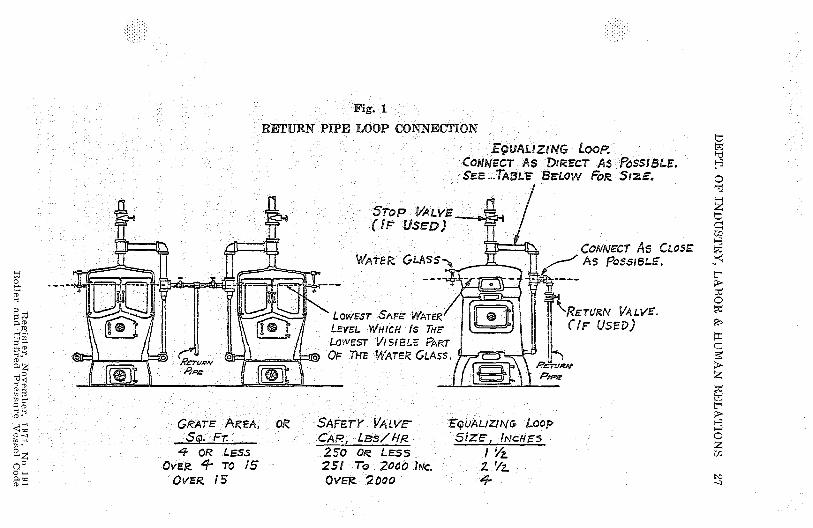
Fog. 1
RETURN PIPE LOOP CONNECTION
FQUALIZING LoopC®AfldEGT AS DIRECT AS POSSIBLE.Sr: p- .._TA5Lr 'S8= OW POP SIZE.
STOP VALVE(IF SE-p )
Comvecr As CLOSEWATER GLASS- - t As Poss ► BLE,
LowFST SAFE W, TER
LEVEL IWwcH Is THE
^{ZETURM VALVE
CIF USED)
LOWEST VIS 1 2LF PAP,T
^ ZC
^ RETLR•Y ^ ^ OF THE WATER GLASS.
R^Ti/R!d
hOPae
Pew^m
m^
cCD
GRATE AKeA, OR SAFETY VALVE-SQUALJZ NG L®0pSo. FT. CAP., LsslRR SIZE, INCH,-5
^z _4 OR _Less 2 5-0 Orz LE5S 1 %2° ? OVE9 4 TO 15 251 To 2000 Iric. 2 `/z
,^^ ovFR 15 OVER '2000 J

28 WISCONSIN ADMINISTRATIVE CODE
Ind 41.89 Combustion regulators for boilers. (1) A temperature com-bustion regulator, which will control the rate of combustion to preventthe temperature of the water from rising above 250 F. at or near theoutlet, or a thermostatic device which will relieve the pressure on theboiler when the temperature exceeds 250 F. shall be used on all hotwater boilers.
(2) When a pressure combustion regulator is used on a steam boiler,it shall operate to prevent the steam pressure from rising above themaximum allowable working pressure for the boiler.
History: Cr. Register, April, 1961, No. 64, eff. 5-1-61.
Ind 41.90 Flanged connections. Openings in boilers having flangedconnections shall have the flanges conform to the A.S.A. (AmericanStandards Association) for the corresponding drilling for -bolts orstuds. Steel outlet nozzles and flanges may be riveted or welded to theshell. Cast iron outlet nozzles or flanges will be permitted only on lowpressure steam or hot water boilers and can be attached to the shellonly by riveting.
Note. Copies of the publication are available for inspection at theoffice of the industrial commission, secretary of state, and revisor ofstatutes or they may be procured for personal use from the AmericanStandards Association, 10 East 40th Street, New York, New York.
History. Cr. Register, April, 1961, No. 64, eff. 5-1-61.
Ind 41.91 Washout and inspection openings. (1) All boilers shall beprovided with suitable manhole or handhole openings, except specialtypes where they are manifestly not needed or used.
(2) All horizontal fire tube boilers shall be required to have thefollowing manhole or handhole openings:
(a) A manhole in the front head below the tubes for:1. Horizontal return tubular power boilers over 54 inches in
diameter.2. Horizontal return tubular low pressure steam or hot water
boilers over 60 inches in diameter.3. For smaller boilers a handhole may be used in place of the
manhole.(b) A manhole in the upper part of the shell or head for:
1. Horizontal return tubular, fire box and locomotive power boilersover '48 inches.
2. Scotch marine power boilers over 54 inches in diameter.3. Low pressure steam boilers over 60 inches in diameter.4. For smaller boilers a handhole may be used in place of the
manhole.(c) Locomotive and fire box boilers shall also have the following
handhole or washout openings:1. One at each of the 4 corners of the lower portion of the water
leg.2. One in the front head at or about the line of the crown sheet.3. One near the throat sheet of power boilers where possible.4. One in the rear head of power boilers below the tubes.
(3) (a) A vertical fire tube boiler, except boilers 24 inches or less indiameter shall have not less than 4 handholes located as follows: 2 inthe shell at or about the line of the -crown sheet or lower tube sheet;2 in the shell at the lower part of the water leg.
(b) Vertical fire tube boilers 24 inches or less in diameter shall have3 one-inch diameter washout plugs except that boilers not exceeding
Register,, November, 1971, No.,1910 r-so

DEPT. OF INDUSTRY, LABOR & HUMAN RELATIONS 29
12 inches internal diameter having less than 10 square 'feet of waterheating surface need not have more than 2 such washout plugs, oneof which may be used for the attachment of the bottom blow-off valve.The threads of the washout plugs shall be of non-ferrous material.
(4) Where handholes are provided, such handholes shall not be lessthan 21/2 'inches by 3 1/z inches in size.
(5) Washout plugs, except for vertical fire tube boilers, shall be notless than 1% 'inch pipe size and shall have threads of non-ferrousmaterials.
(6) 'Every cast iron boiler shall be provided with washout openingsto permit the removal of any sediment that may accumulate therein.Washout openings may be used for return pipe connection if the wash-out plug is placed in a tee so that the plug is directly opposite and asclose as possible to the opening in the boiler.
history: Cr. Register, April, 1961, No. 64, eff. 5-1-61.
Ind 41.92 Manholes. Where manholes are provided, such manholesshall be not less than 11 inches by 15 inches, or 10 inches by 16 inchesin size. A circular manhole opening shall be not less than 15 inches indiameter.
History: Cr. Register, April, 1961, No. 64, eff, 5-1-61.
Ind 41.93 Maintenance. (1) All boilers shall be installed and main-tained in such a manner as to prevent excessive corrosion or deteriora-tion.
(2) The inspector shall note conditions during the internal inspec-tion, external inspection or hydrostatic pressure test and ,order suchchanges or repairs as will place the boiler in a safe working condition.
History: Cr. Register, April, 1961, No. 64, eff. 5-1-61.
Ind 41.94 iThreaded openings. (1) All pipe threads shall conform tothe American Pipe Thread standard and all connections one inch pipesize or over shall have not less than the number of threads given inTable 6. For smaller pipe connections there shall be at least 4 threadsin the opening.
(2) If the thickness of the shell of the boiler is not sufficient to givesuch number of threads a construction shall be employed which willprovide at least the required number of threads.
TABU; tiMINIMUM NUMBER OF PIPE THREADS FOR CONNECTIONS
TO BOILERS
Size of pipe connections,inches_________________ 1 & 1% & 2% to 4% to 7 & 8 9 & 10 12
IX 2 4 inel 6 inelNumber of threadsper inch_______________ 11Y 11% 8 8 8 8 8
Minimum number ofthreads required foropening_______________ 4 5 7 8 10 12 13
Minimum thickness ofmaterial required to giveabove number of threads,inches_________________ 0.348 0.435 0.875 1 1.25 1.5 1.6265
Note. Copies of the publication are available for inspection at the officeof the industrial <commission, secretary of state, and revisor of statutesor they may be procured for personal use from the American SitandardsAssociation, 10 'East 40th Street, New York, New York, or the AmericanSociety of Mechanical Engineers, 29 West 39th Street, New York 18, NewYork.
History: Cr. Register, April, 1961, No. 64, eff. 5-1-61.
Register, November, 1971, No 191Boiler and Unfirerl Praaanrr. 1T—.1 (1-1n
30 WISCONSIN ADMINISTRATIVE CODE
Ind 41.95 Boiler setting and installation. (1) A horizontal returntubular boiler over 72 inches in diameter shall be supported from steelhangers by the outside suspension type of setting, independent of theboiler side walls. The hangers shall be so designed that the load isproperly distributed between the rivets attaching them to the shelland so that no more than 2 of these rivets come in the same longi-tudinal line on each hanger. The distance girthwise of the boiler fromthe centers of the bottom rivets to the center of the top rivets attach-ing the hangers shall be not less than 12 inches. The other rivets usedshall be spaced evenly between these points. If more than 4 hangersare used they shall be set in 4 pairs.
(2) A horizontal return tubular boiler over 54 inches and up to andincluding 72 inches in diameter, shall be supported by the outside sus-pension type of setting, or at 4 points by not less than S steel or castiron brackets, set in pairs. A horizontal return tubular boiler up toand including 54 inches in diameter shall be supported by the outsidesuspension type of setting, or by not less than 2 steel or cast ironbrackets on each side.
'(3) Lugs or hangers, when used to support a boiler of any type shallbe properly fitted to the surfaces to which they are attached. If riv-eted, the shearing and crushing stresses on the rivets used for attach-ing the lugs or ha °gers shall not exceed 8% of the strength given insection Ind 41.72'VVhere it is impractical to use rivets, studs with notless than 10 threads per inch may be used. In computing the shearingstress, the area at the bottom of the thread shall be used. Strengthwelding may . Yee used, if done in accordance with sections Ind 41.50',and Ind 41.51 of this code.
(4) Wet bottom stationary boilers shall have a space of not lessthan 12 inches between the bottom of the boiler and the floor line, withaccess for inspection.
(5) The upper surface of the fire grate of an internally fired boilerof the open bottom locomotive, vertical fire tube or similar type, shallnot be below the water space in the water leg, except where the rivetsat the bottom of the water leg are protected from the action of thefire and products of combustion.
History: Cr. Register, April, 1961, No. 64, eff. 5-1-61.
Ind 41.96 Access and firing doors. The minimum size of an accessdoor to be placed in a boiler setting shall be 12 inches by 16 inches orequivalent area, 11 inches to be the least dimension in any case.-History: Cr. Register, April, 1961, No. 64, eff. 5-1-61.
Ind 41.97 Water tube boiler doors. A water tube boiler shall havethe firing doors, furnace inspection doors and clinker doors of theinward opening type, unless such doors are provided with latching orfastening devices or otherwise so constructed as to prevent them, whenclosed, from being blown open by pressure on the furnace side.
History: Cr. Register, April, 1961, No. 64, eff. 5-1-61.
Ind 41.99 Low-water cut-off and water feeder. (1) Every automati-cally fired power boiler which does not have a full time attendant andevery, automatically fired low pressure steam boiler shall be equippedwith an automatic low-water fuel cut-off or other device which willperform a similar function, so located as to automatically cut off thefuel supply when the surface of the water falls to the lowest safe
Register, November, 1971, No. 191Boiler and Unflred Pressure Vessel Code

DEPT. OF INDUSTRY, LABOR & HUMAN RELATIONS 31
water line. If a water feeding device is installed, it shall be so con-structed that the water inlet valve cannot feed water into the boilerthrough the float chamber and so located as to supply requisite feedwater. The lowest safe water line shall be not lower than the lowestvisible part of the water glass.
(2) Such a fuel or feed water control device may be attached directto a boiler or to the topped openings provided for attaching a waterglass direct to a boiler, provided that such connections from the boilerare non-ferrous tees or Y's not less than i/a inch pipe size betweenthe boiler and the water glass so that the water glass is attacheddirect and as close as possible to the boiler; the straightway tappingof the Y or tee to take the water glass fittings, the side outlet of theY or tee to take the fuel cut-off or water-feeding device. The ends ofall nipples shall be reamed to full size diameter.
(3) Designs embodying a float and float bowl, or probe controlsinstalled in a bowl or chamber externally to the boiler shall have avertical straightway valved drain pipe at the lowest point in the waterequalizing pipe, connections by which the bowl or chamber and theequalizing pipe can be flushed and the device tested.
History: Cr. Register, April, 1961, No. 64, eff. 5-1-61.
Ind 41.99 Pressure relief devices required for unfired pressurevessels. (1) Every unfired pressure vessel shall be provided with orprotected by a pressure relief device.
(2) The relieving capacity of the pressure relief device shall beequal to or greater than the input to the vessel or shall be greatenough to prevent the pressure in the vessel from rising more than10% above the maximum allowable working pressure of the vessel.
(3) Safety valves whichare/constructed i accordance with thestandards of sections Ind 41.5 and Ind 41.51: of this code are accept-able. Safety valves constructed to other standards may be used ifapproved by the industrial commission.
(4) Rupture disks may be used in lieu of safety valves on vesselscontaining substances that may render a safety valve inoperative, orwhere a loss of valuable material by leakage should be avoided, orcontamination of the atmosphere by leakage of noxious gases must beavoided. Such rupture disks shall be tested, marked, and installled inaccordance with the A.S.M.E. codes listed in section Ind 41.50."v/
(5) When hot, water supply is heated indirectly by steam in a coilor pipe a water relief valve of at least one inch in diameter, set torelieve at or below the maximum allowable working pressure of thetank shall be used.
(6) Each safety or relief valve shall have a full size direct connec-tion to the pressure vessel. When an escape pipe is used it shall befull sized and fitted with an open drain, to prevent water lodging inthe ;upper 'part of the safety or relief valve or escape pipe. When apressure vessel is fitted with 2 safety or relief valves on one connec-tion, this connection to the pressure vessel shall have a cross-sectionalarea equal to or greater than the combined area of the 2 safety orrelief valves. No valve of any description shall be placed between thesafety or relief valve and the pressure vessel, nor on the escape pipebetween the safety or relief valve and the atmosphere.
Boil Register
, November, 1971, No ,191er and Unfired Pressure Vessel Code
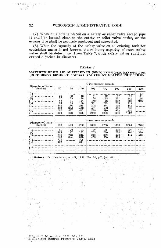
32 WISCONSIN ADMINISTRATIVE CODE
(7) When an elbow is placed on a safety or relief valve escape pipeit shall be located close to the safety or relief valve outlet, or theescape pipe shall be securely anchored and supported.
(8) When the capacity of the safety valve on an existing tank forcontaining gases is not known, the relieving capacity of such safetyvalve shall be determined from Table 7. Such safety valves shall notexceed 4 inches in diameter.
TABLE 7
MAXIMUM FREE AIR SUPPLIED IN CUBIC FEET PER MINUTE FOR(DIFFERENT SIZES OF SAFETY VALVES AT STATED PRESSURES
Gage pressure, poundsDiameter of Valve --- — — —
"(inches) 50 100 150 200 250 300 350 400
X -------------- ------- - ------ ------- --- - 53;2-------------- 20 32 42 51 59 67 74 < 111
-------------- 37 59 78 96 112 127 141 1761'"-------------- 58 94 124 152 178 202 224 2481 Y4 -------------- 84 135 180 221 259 293 325 -------1>2-------------- 114 186 248 302 354 400 444 -------2 -------------- 189 306 410 501 592 668 741 -------2 Y2 -------------- 282 457 613 750 880 998 1114 -------3 -------------- 393 638 856 1050 1230 1398 1557 -------
Gage pressure, pounds -Diameter of Valve — -- —
(inches) 500 600 800 1000 1200 1600 2000 2400
-------------- 61 70 84 97 109 128 147 167-------------- 129 147 177 205 230 270 304 330-------------- 224 232 242 346 386 423 474 518
1 -------------- 286 324 ' 390 460 500 586 -------- -------1 Y4 -------------- 374 ' ------- 509 -------- -------- ------ -- ------- -------1%-------------- 472 ------- 634 -------- -------- -- ------ -------- -------2 -------------- ------- ------- -- ----- -------- -------- -- ------ -------- -- -----2Y--------------- ------- ------- - ------ -------- -------- -- ------ -------- -------`l-------------- ------- ------- - ------ ---- --____- _.- - -
Iliartury: Cr. Register, April, 1961, No. 64, eff. 5-1-61.
Register, November, 1971, No. 191Boiler and Unfired Pressure Vessel Code