body interior adp a -...
TRANSCRIPT

BODY INTERIOR
C
D
E
SECTION ADPA
B
AUTOMATIC DRIVE POSITIONER
F
G
H
I
K
L
M
DP
N
O
P
CONTENTS
A
BASIC INSPECTION .................................... 5
DIAGNOSIS AND REPAIR WORKFLOW .......... 5Work Flow .................................................................5
INSPECTION AND ADJUSTMENT ..................... 8Preliminary Check .....................................................8Special Repair Requirement .....................................8
FUNCTION DIAGNOSIS ............................... 9
AUTOMATIC DRIVE POSITIONER SYSTEM ..... 9
AUTOMATIC DRIVE POSITIONER SYSTEM .............9AUTOMATIC DRIVE POSITIONER SYSTEM : System Diagram ........................................................9AUTOMATIC DRIVE POSITIONER SYSTEM : Component Parts Location ......................................10AUTOMATIC DRIVE POSITIONER SYSTEM : System Description .................................................10AUTOMATIC DRIVE POSITIONER SYSTEM : Component Description ..........................................11
MANUAL FUNCTION ................................................12MANUAL FUNCTION : System Diagram ................13MANUAL FUNCTION : System Description ............13MANUAL FUNCTION : Component Parts Loca-tion ..........................................................................14MANUAL FUNCTION : Component Description ....15
MEMORY FUNCTION ...............................................16MEMORY FUNCTION : System Diagram ...............16MEMORY FUNCTION : System Description ..........16MEMORY FUNCTION : Component Parts Loca-tion ..........................................................................18MEMORY FUNCTION : Component Description ....18
EXIT ASSIST FUNCTION ..........................................19EXIT ASSIST FUNCTION : System Diagram .........19EXIT ASSIST FUNCTION : System Description .....20EXIT ASSIST FUNCTION : Component Parts Lo-cation .......................................................................21
EXIT ASSIST FUNCTION : Component Description ..........................................21
ENTRY ASSIST FUNCTION ......................................22ENTRY ASSIST FUNCTION : System Diagram .....22ENTRY ASSIST FUNCTION : System Description
....22ENTRY ASSIST FUNCTION : Component Parts Location ...................................................................23ENTRY ASSIST FUNCTION : Component Description ..........................................24
DIAGNOSIS SYSTEM (DRIVER SEAT C/U) ....25Diagnosis Description ..............................................25CONSULT-III Function ............................................25
COMPONENT DIAGNOSIS .........................28
U1000 CAN COMM CIRCUIT ...........................28Description ...............................................................28DTC Logic ................................................................28Diagnosis Procedure ..............................................28Special Repair Requirement ....................................28
B2112 SLIDING MOTOR ..................................29Description ...............................................................29DTC Logic ................................................................29Diagnosis Procedure ..............................................29
B2113 RECLINING MOTOR .............................30Description ...............................................................30DTC Logic ................................................................30Diagnosis Procedure ..............................................30
B2114 SEAT LIFTER FR ..................................31Description ...............................................................31DTC Logic ................................................................31Diagnosis Procedure ..............................................31
B2115 SEAT LIFTER RR ..................................32Description ...............................................................32DTC Logic ................................................................32
ADP-1
Diagnosis Procedure ............................................. 32
B2117 ADJ PEDAL MOTOR ............................. 33Description .............................................................. 33DTC Logic ............................................................... 33Diagnosis Procedure ............................................. 33
B2120 ADJ PEDAL SENSOR ........................... 35Description .............................................................. 35DTC Logic ............................................................... 35Diagnosis Procedure ............................................. 35
B2126 DETENT SW ........................................... 37Description .............................................................. 37DTC Logic ............................................................... 37Diagnosis Procedure ............................................. 37
B2128 UART COMMUNICATION LINE ............ 39Description .............................................................. 39DTC Logic ............................................................... 39Diagnosis Procedure ............................................. 39
POWER SUPPLY AND GROUND CIRCUIT ..... 41
BCM ........................................................................... 41BCM : Diagnosis Procedure ................................... 41
DRIVER SEAT CONTROL UNIT .............................. 41DRIVER SEAT CONTROL UNIT : Diagnosis Procedure ............................................. 42DRIVER SEAT CONTROL UNIT : Special Repair Requirement ........................................................... 42
AUTOMATIC DRIVE POSITIONER CONTROL UNIT .......................................................................... 42
AUTOMATIC DRIVE POSITIONER CONTROL UNIT : Diagnosis Procedure .................................. 42AUTOMATIC DRIVE POSITIONER CONTROL UNIT : Special Repair Requirement ....................... 43
SLIDING SWITCH .............................................. 44Description .............................................................. 44Component Function Check ................................. 44Diagnosis Procedure ............................................. 44Component Inspection ............................................ 45
RECLINING SWITCH ........................................ 46Description .............................................................. 46Component Function Check ................................. 46Diagnosis Procedure ............................................. 46Component Inspection ............................................ 47
LIFTING SWITCH (FRONT) .............................. 48Description .............................................................. 48Component Function Check ................................. 48Diagnosis Procedure ............................................. 48Component Inspection ............................................ 49
LIFTING SWITCH (REAR) ................................. 50Description .............................................................. 50Component Function Check ................................. 50Diagnosis Procedure ............................................. 50
Component Inspection ............................................ 51
PEDAL ADJUSTING SWITCH .......................... 52Description .............................................................. 52Component Function Check .................................. 52Diagnosis Procedure .............................................. 52Component Inspection ............................................ 54
SEAT MEMORY SWITCH ................................. 55Description .............................................................. 55Component Function Check .................................. 55Diagnosis Procedure .............................................. 55Component Inspection ............................................ 56
DOOR MIRROR REMOTE CONTROL SWITCH ............................................................. 57
CHANGEOVER SWITCH .......................................... 57CHANGEOVER SWITCH : Description .................. 57CHANGEOVER SWITCH : Component Function Check ...................................................................... 57CHANGEOVER SWITCH : Diagnosis Procedure ... 57CHANGEOVER SWITCH : Component Inspec-tion .......................................................................... 58
MIRROR SWITCH ..................................................... 59MIRROR SWITCH : Description ............................. 59MIRROR SWITCH : Component Function Check ... 59MIRROR SWITCH : Diagnosis Procedure .............. 59MIRROR SWITCH : Component Inspection ........... 61
POWER SEAT SWITCH GROUND CIRCUIT ... 62Diagnosis Procedure .............................................. 62
DETENTION SWITCH ....................................... 63Description .............................................................. 63Component Function Check .................................. 63Diagnosis Procedure .............................................. 63
FRONT DOOR SWITCH (DRIVER SIDE) ......... 65Description .............................................................. 65Component Function Check ................................... 65Diagnosis Procedure ............................................... 65Component Inspection ............................................ 65
SLIDING SENSOR ............................................ 67Description .............................................................. 67Component Function Check .................................. 67Diagnosis Procedure .............................................. 67
RECLINING SENSOR ....................................... 69Description .............................................................. 69Component Function Check .................................. 69Diagnosis Procedure .............................................. 69
LIFTING SENSOR (FRONT) ............................. 71Description .............................................................. 71Component Function Check .................................. 71Diagnosis Procedure .............................................. 71
LIFTING SENSOR (REAR) ............................... 73Description .............................................................. 73
ADP-2
C
D
E
F
G
H
I
K
L
M
A
B
DP
N
O
P
A
Component Function Check ..................................73Diagnosis Procedure ..............................................73
PEDAL ADJUSTING SENSOR ..........................75Description ..............................................................75Component Function Check ..................................75Diagnosis Procedure ..............................................75
MIRROR SENSOR .............................................77
DRIVER SIDE ............................................................77DRIVER SIDE : Description ....................................77DRIVER SIDE : Component Function Check ........77DRIVER SIDE : Diagnosis Procedure ....................77
PASSENGER SIDE ...................................................79PASSENGER SIDE : Description ...........................79PASSENGER SIDE : Component Function Check ..................................79PASSENGER SIDE : Diagnosis Procedure ...........79
SLIDING MOTOR ...............................................81Description ..............................................................81Component Function Check ..................................81Diagnosis Procedure ..............................................81
RECLINING MOTOR ..........................................83Description ..............................................................83Component Function Check ..................................83Diagnosis Procedure ..............................................83
LIFTING MOTOR (FRONT) ................................85Description ..............................................................85Component Function Check ..................................85Diagnosis Procedure ..............................................85
LIFTING MOTOR (REAR) ..................................87Description ..............................................................87Component Function Check ..................................87Diagnosis Procedure ..............................................87
PEDAL ADJUSTING MOTOR ............................89Description ..............................................................89Component Function Check ..................................89Diagnosis Procedure ..............................................89
DOOR MIRROR MOTOR ...................................91Description ..............................................................91Component Function Check ....................................91Diagnosis Procedure ...............................................91Component Inspection ............................................93
SEAT MEMORY INDICATOR LAMP .................94Description ..............................................................94Component Function Check ..................................94Diagnosis Procedure ..............................................94Component Inspection ............................................95
ECU DIAGNOSIS .........................................96
DRIVER SEAT CONTROL UNIT ........................96Reference Value .....................................................96
Wiring Diagram ......................................................101Fail Safe ................................................................115DTC Index .............................................................116
AUTOMATIC DRIVE POSITIONER CON-TROL UNIT ...................................................... 117
Reference Value ....................................................117Wiring Diagram ......................................................120
BCM (BODY CONTROL MODULE) ............... 135Reference Value ....................................................135Terminal Layout .....................................................138Physical Values .....................................................138Wiring Diagram ......................................................144Fail Safe ................................................................147DTC Inspection Priority Chart .............................148DTC Index .............................................................148
SYMPTOM DIAGNOSIS ............................ 150
ADP SYSTEM SYMPTOMS ............................ 150Symptom Table .....................................................150
NORMAL OPERATING CONDITION ............. 152Description .............................................................152
PRECAUTION ............................................ 153
PRECAUTIONS ............................................... 153Precaution for Supplemental Restraint System (SRS) "AIR BAG" and "SEAT BELT PRE-TEN-SIONER" ...............................................................153Precaution Necessary for Steering Wheel Rota-tion After Battery Disconnect .................................153Precaution for Work ...............................................153
ON-VEHICLE MAINTENANCE .................. 155
PRE-INSPECTION FOR DIAGNOSTIC .......... 155Basic Inspection ....................................................155
PREPARATION ......................................... 157
PREPARATION ............................................... 157Special Service Tool ..............................................157Commercial Service Tool ......................................157
ON-VEHICLE REPAIR ............................... 158
DRIVER SEAT CONTROL UNIT .................... 158Removal and Installation .......................................158
AUTOMATIC DRIVE POSITIONER CON-TROL UNIT ...................................................... 159
Removal and Installation .......................................159
SEAT MEMORY SWITCH ............................... 160Removal and Installation .......................................160
DOOR MIRROR REMOTE CONTROL SWITCH ........................................................... 161
Removal and Installation .......................................161
ADP-3

PEDAL ADJUSTING MOTOR ......................... 162 Removal and Installation ....................................... 162
ADP-4

DIAGNOSIS AND REPAIR WORKFLOW
C
D
E
F
G
H
I
K
L
M
A
B
DP
N
O
P
< BASIC INSPECTION >
A
BASIC INSPECTIONDIAGNOSIS AND REPAIR WORKFLOW
Work Flow INFOID:0000000003935450
WORK FLOW
DETAILED FLOW
ALKIA0538GB
ADP-5

DIAGNOSIS AND REPAIR WORKFLOW
< BASIC INSPECTION >1. GET INFORMATION FOR SYMPTOM
Get the detailed information from the customer about the symptom (the condition and the environment whenthe incident/malfunction occurred).
>> GO TO 2
2. CHECK DTC WITH AUTOMATIC DRIVE POSITIONER SYSTEM
Check “Self Diagnostic Result” with CONSULT-III.Refer to ADP-116, "DTC Index".Is any symptom described and any DTC is displayed?Symptom is described, DTC is displayed.>>GO TO 3Symptom is not described, DTC is displayed.>>GO TO 7Symptom is described, DTC is not displayed.>>GO TO 4
3. CONFIRM THE SYMPTOM
Try to confirm the symptom described by the customer.
>> GO TO 7
4. CONFIRM THE SYMPTOM
Try to confirm the symptom described by the customer.
>> GO TO 5
5. CHECK NORMAL OPERATING CONDITION
Check normal operating condition. Refer to ADP-152, "Description".Is the incident normal operation?YES >> Inspection End.NO >> GO TO 6
6. PERFORM BASIC INSPECTION
Isolate the malfunctioning point with the basic inspection. Refer to ADP-8, "Preliminary Check".
>> GO TO 8
7. PERFORM DTC CONFIRMATION PROCEDURE
Perform the confirmation procedure for the detected DTC.Is the DTC displayed?YES >> GO TO 9NO >> Check intermittent incident. Refer to GI-49, "Intermittent Incident".
8. PERFORM COMPONENT FUNCTION CHECK
Perform the component function check for the isolated malfunctioning point.
>> GO TO 9
9. DETECT MALFUNCTIONING PART BY DIAGNOSTIC PROCEDURE
Isolate the malfunctioning point by performing the diagnosis procedure relevant to the symptom during thecomponent diagnosis.
>> GO TO 10
10. REPAIR OR REPLACE
Repair or replace the malfunctioning part.
ADP-6

DIAGNOSIS AND REPAIR WORKFLOW
C
D
E
F
G
H
I
K
L
M
A
B
DP
N
O
P
< BASIC INSPECTION >
A
>> GO TO 11
11. FINAL CHECK
Perform the DTC confirmation procedure (if DTC is detected) or component function check (if no DTC isdetected) again, and then check that the malfunction can be repaired securely.Are all malfunctions corrected?YES >> Inspection End.Symptom is detected.>> GO TO 4DTC is detected.>> GO TO 7
ADP-7

INSPECTION AND ADJUSTMENT
< BASIC INSPECTION >INSPECTION AND ADJUSTMENT
Preliminary Check INFOID:0000000003935451
1. FOREIGN OBJECTS
Check the following:• objects on or behind the seats that could cause binding• objects under the seats that may be interfering with the seat’s moving parts• objects under pedals that may interfere with movementAre there any foreign objects that could be causing interference?YES >> Remove objects.NO >> GO TO 2
2. WIRING CONNECTIONS
1. Disconnect harness connectors.2. Check terminals for damage or loose connections. 3. Reconnect harness connectors.Are any connectors damaged or loose?YES >> Repair or replace damaged parts.NO >> GO TO 3
3. POWER AND GROUND
Check power supply and ground circuits for control unit. Refer to ADP-42, "DRIVER SEAT CONTROL UNIT :Diagnosis Procedure".Is the inspection result normal?YES >> Refer to ADP-116, "DTC Index".NO >> Repair or replace as necessary.
Special Repair Requirement INFOID:0000000003935452
Refer to Owner’s Manual for Automatic Drive Positioner system operating instructions.
ADP-8

AUTOMATIC DRIVE POSITIONER SYSTEM
C
D
E
F
G
H
I
K
L
M
A
B
DP
N
O
P
< FUNCTION DIAGNOSIS >
A
FUNCTION DIAGNOSISAUTOMATIC DRIVE POSITIONER SYSTEMAUTOMATIC DRIVE POSITIONER SYSTEM
AUTOMATIC DRIVE POSITIONER SYSTEM : System Diagram INFOID:0000000003935453
ALJIA0243GB
ADP-9

AUTOMATIC DRIVE POSITIONER SYSTEM
< FUNCTION DIAGNOSIS >AUTOMATIC DRIVE POSITIONER SYSTEM : Component Parts Location INFOID:0000000003935454
AUTOMATIC DRIVE POSITIONER SYSTEM : System Description INFOID:0000000003935455
OUTLINEThe system automatically moves the driver seat, pedal assembly and door mirror position by the driver seatcontrol unit and the automatic drive positioner control unit. The driver seat control unit corresponds with theautomatic drive positioner control unit by UART communication.
LIIA2405E
1. A. BCM M18, M19, M20B. Pedal adjusting motor E109, E110 (view with lower instrument panel LH removed)
2. A. Door mirror LH D18, RH D118B. Front door switch LH B8
3. Seat memory switch D5
4. A. Pedal adjusting switch M96B. Door mirror remote control switch M163
5. A. A/T deviceB. A/T device (park position switch) M156
6. A. Sliding motor LH B204, reclining motor LH B232, lifting motor (front) B206, lifting motor (rear) B207B. Driver seat control unit B202, B203C. Power seat switch LH B208(front seat LH view)
7. A. Automatic drive positioner control unit M33, M34B. Circuit breaker-2 M82 (view with instrument panel removed)
Function Description
Manual functionThe driving position (seat, pedal assembly and door mirror position) can be adjusted by using the power seat switch, pedal adjusting switch or door mirror remote control switch.
Memory functionThe seat, pedal assembly and outside mirror move to the stored driving position by pressing seat memory switch (1 or 2).
ADP-10

AUTOMATIC DRIVE POSITIONER SYSTEM
C
D
E
F
G
H
I
K
L
M
A
B
DP
N
O
P
< FUNCTION DIAGNOSIS >
A
AUTOMATIC DRIVE POSITIONER SYSTEM : Component Description INFOID:0000000003935456
CONTROL UNITS
INPUT PARTS
Switches
Entry/Exit assist functionExit On exit, the seat moves backward.
Entry On entry, the seat returns from exiting position to the previous driving position.
Keyfob interlock functionPerform memory operation, exiting operation and entry operation by key unlock oper-ation.
Intelligent Key interlock functionPerform memory operation, exiting operation and entry operation by Intelligent Key unlock operation or driver side door request switch unlock operation .
Function Description
Item Function
Driver seat control unit
• Main unit of automatic drive positioner system• It is connected to the CAN.• It communicates with the automatic drive positioner control unit via UART com-
munication.
Automatic drive positioner control unit
• It communicates with the driver seat control unit via UART communication.• Perform various controls with the instructions of driver seat control unit.• Perform the controls of the pedal adjusting, door mirror and the seat memory
switch.
BCM
Transmit the following status to the driver seat control unit via CAN communication.• Front door LH: OPEN/CLOSE• Ignition switch position: ACC/ON• Door lock: UNLOCK (with Intelligent Key or remote keyless entry request switch
operation)• Key ID• Key switch: Insert/Pull out Intelligent Key or ignition key• Starter: CRANKING/OTHER
Combination meterTransmit the vehicle speed signal to the driver seat control unit via CAN communi-cation.
AV control unit The setting change of auto drive positioner system can be performed on the display.
A/T device (park position switch) Transmit the shift position signal (P range) to the driver seat control unit.
Item Function
Key switch and ignition knob switch The key switch is installed to detect the key inserted/removed status.
Front door switch LH Detect front door (driver side) open/close status.
A/T device (park position switch) Detect the P range position of A/T selector lever.
Set switch The registration and system setting can be performed with its operation.
Seat memory switch 1/2 The registration and operation can be performed with its operation.
Power seat switch
The following switch is installed.• Reclining switch• Lifting switch (front)• Lifting switch (rear)• Sliding switchThe specific parts can be operated with the operation of each switch.
ADP-11

AUTOMATIC DRIVE POSITIONER SYSTEM
< FUNCTION DIAGNOSIS >Sensors
OUTPUT PARTS
MANUAL FUNCTION
Pedal adjusting switch
The following switch is installed.• Pedal forward• Pedal backwardThe specific parts can be operated with the operation of each switch.
Door mirror remote control switch
The following switch is installed.• Mirror switch• Changeover switchThe specific parts can be operated with the operation of each switch.
Item Function
Item Function
Door mirror sensor (LH/RH) Detect the up/down and left/right position of outside mirror face.
Pedal adjusting sensor Detect the forward/backward position of pedal assembly.
Lifting sensor (front) Detect the up/down position of seat lifting (front).
Lifting sensor (rear) Detect the up/down position of seat lifting (rear).
Reclining sensor Detect the tilt of seatback.
Sliding sensor Detect the front/rear position of seat.
Item Function
Door mirror motor (LH/RH) Move the outside mirror face up/down and left/right.
Pedal adjusting motor Move the pedal assembly forward/backward.
Lifting motor (front) Move the seat lifting (front) up/down.
Lifting motor (rear) Move the seat lifting (rear) up/down.
Reclining motor Tilt and raise up the seatback.
Sliding motor Slide the seat forward/backward.
Seat memory indicator Illuminates or flashes according to the registration/operation status.
ADP-12

AUTOMATIC DRIVE POSITIONER SYSTEM
C
D
E
F
G
H
I
K
L
M
A
B
DP
N
O
P
< FUNCTION DIAGNOSIS >
A
MANUAL FUNCTION : System Diagram INFOID:0000000003935457
MANUAL FUNCTION : System Description INFOID:0000000003935458
OUTLINEThe driving position (seat, pedal assembly and door mirror position) can be adjusted manually with power seatswitch, pedal adjusting switch and door mirror remote control switch.
OPERATION PROCEDURE1. Turn ignition switch ON.2. Operate power seat switch, pedal adjusting switch or door mirror remote control switch.3. The driver seat, pedal assembly or door mirror operates according to the operation of each switch.
DETAIL FLOW
Seat
Adjustable pedals
ALJIA0185GB
Order Input Output Control unit condition
1Power seat switch(sliding, lifting, reclin-ing)
—The power seat switch signal is input to the driver seat control unit when the power seat switch is operated.
2 —Motors(sliding, lifting, reclin-ing)
The driver seat control unit outputs signals to each motor accord-ing to the power seat switch input signal.
Order Input Output Control unit condition
1 Pedal adjusting switch —The pedal adjusting switch signal is input to the automatic drive positioner control unit when the pedal adjusting switch is operat-ed.
ADP-13
AUTOMATIC DRIVE POSITIONER SYSTEM
< FUNCTION DIAGNOSIS >Door Mirror
NOTE:The door mirrors can be operated manually when ignition switch is in either ACC or ON position. The ignitionswitch signal (ACC/ON) is transmitted from BCM to the driver seat control unit via CAN communication andfrom the driver seat control unit to the automatic drive positioner control unit via UART communication.
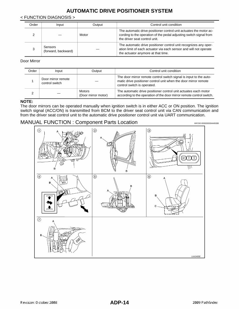
MANUAL FUNCTION : Component Parts Location INFOID:0000000004449386
2 — MotorThe automatic drive positioner control unit actuates the motor ac-cording to the operation of the pedal adjusting switch signal from the driver seat control unit.
3Sensors(forward, backward)
—The automatic drive positioner control unit recognizes any oper-ation limit of each actuator via each sensor and will not operate the actuator anymore at that time.
Order Input Output Control unit condition
Order Input Output Control unit condition
1Door mirror remote control switch
—The door mirror remote control switch signal is input to the auto-matic drive positioner control unit when the door mirror remote control switch is operated.
2 —Motors(Door mirror motor)
The automatic drive positioner control unit actuates each motor according to the operation of the door mirror remote control switch.
LIIA2405E
ADP-14

AUTOMATIC DRIVE POSITIONER SYSTEM
C
D
E
F
G
H
I
K
L
M
A
B
DP
N
O
P
< FUNCTION DIAGNOSIS >
A
MANUAL FUNCTION : Component Description INFOID:0000000003935460
CONTROL UNITS
INPUT PARTS
Switches
Sensors
OUTPUT PARTS
1. A. BCM M18, M19, M20B. Pedal adjusting motor E109, E110 (view with lower instrument panel LH removed)
2. A. Door mirror LH D18, RH D118B. Front door switch LH B8
3. Seat memory switch D5
4. A. Pedal adjusting switch M96B. Door mirror remote control switch M163
5. A. A/T deviceB. A/T device (park position switch) M156
6. A. Sliding motor LH B204, reclining motor LH B232, lifting motor (front) B206, lifting motor (rear) B207B. Driver seat control unit B202, B203C. Power seat switch LH B208(front seat LH view)
7. A. Automatic drive positioner control unit M33, M34B. Circuit breaker-2 M82 (view with instrument panel removed)
Item Function
Driver seat control unit
• Operates the specific seat motor with the signal from the power seat switch.• Transmits the ignition switch signal (ACC/ON) via UART communication to the
automatic drive positioner control unit.• Transmits the pedal adjusting switch signal via UART communication to the au-
tomatic drive positioner control unit.
Automatic drive positioner control unitOperates the specific motor with the signal from driver seat control unit or door mir-ror remote control switch.
BCMRecognizes the following status and transmits it to the driver seat control unit via CAN communication.• Ignition position: ACC/ON
Item Function
Power seat switch
The following switch is installed.• Reclining switch• Lifting switch (front)• Lifting switch (rear)• Sliding switchThe specific parts can be operated with the operation of each switch.
Pedal adjusting switch
The following switch is installed.• Pedal forward• Pedal backwardThe specific parts can be operated with the operation of each switch.
Door mirror remote control switch
The following switch is installed.• Mirror switch• Changeover switchThe specific parts can be operated with the operation of each switch.
Item Function
Pedal adjusting sensor Detect the forward/backward position of pedal assembly.
ADP-15

AUTOMATIC DRIVE POSITIONER SYSTEM
< FUNCTION DIAGNOSIS >MEMORY FUNCTION
MEMORY FUNCTION : System Diagram INFOID:0000000003935461
MEMORY FUNCTION : System Description INFOID:0000000003935462
OUTLINEThe driver seat control unit can store the optimum driving positions (seat, pedal assembly and door mirrorposition) for 2 people. If the front seat position is changed, one-touch (pressing desired memory switch formore than 0.5 second) operation allows changing to the other driving position.NOTE:Further information for the memory storage procedure. Refer to Owner’s Manual.
OPERATION PROCEDURE1. Turn ignition switch ON2. Press desired memory switch for more than 0.5 second.3. Front seat LH, pedal assembly and door mirror will move to the memorized position.
OPERATION CONDITIONSatisfy all of the following items. The memory function is not performed if these items are not satisfied.
Item Function
Door mirror motor (LH/RH) Move the outside mirror face up/down and left/right.
Pedal adjusting motor Move the pedal assembly forward/backward.
Lifting motor (front) Move the seat lifter (front) up/down.
Lifting motor (rear) Move the seat lifter (rear) up/down.
Reclining motor Tilt and raise up the seatback.
Sliding motor Slide the seat forward/backward.
ALJIA0187GB
ADP-16

AUTOMATIC DRIVE POSITIONER SYSTEM
C
D
E
F
G
H
I
K
L
M
A
B
DP
N
O
P
< FUNCTION DIAGNOSIS >
A
DETAIL FLOW
Item Request status
Ignition position ON
Switch inputs• Power seat switch• Pedal adjusting switch• Door mirror control switch• Set switch• Seat memory switch
OFF(Not operated)
A/T selector lever P position
Order Input Output Control unit condition
1 Memory switch —
The memory switch signal is inputted to the automatic drive positioner control unit when memory switch 1 or 2 is operated.Memory switch signal is input to driver seat control unit via UART communication.
2 —
Motors(seat, pedal adjusting, door mirror)
Driver seat control unit operates each motor of seat when it recogniz-es the memory switch pressed for 0.5 second or more and requests each motor operation to automatic drive positioner control unit via UART communication. The automatic drive positioner control unit op-erates each motor.
Memory switch Indica-tor
Driver seat control unit requests the flashing of memory indicator to automatic drive positioner control unit via UART communication while either of the motors is operating. The automatic drive positioner con-trol unit illuminates the memory indicator.
3Sensors(seat, pedal adjust-ing, door mirror)
—
Driver seat control unit judges the operating seat position with each seat sensor input. The positions of the adjustable pedals and outside mirror are monitored with each sensor signal that is input from auto drive positioner control unit via UART communication. Driver seat control unit stops the operation of each motor when each part reach-es the recorded address.
4 —Memory switch Indica-tor
Driver seat control unit requests the illumination of memory indicator to auto drive positioner control unit via UART communication after all motors stop. The auto driving positioner control unit illuminates the memory indicator for 5 seconds.
ADP-17

AUTOMATIC DRIVE POSITIONER SYSTEM
< FUNCTION DIAGNOSIS >MEMORY FUNCTION : Component Parts Location INFOID:0000000004449387
MEMORY FUNCTION : Component Description INFOID:0000000003935464
CONTROL UNITS
INPUT PARTS
LIIA2405E
1. A. BCM M18, M19, M20B. Pedal adjusting motor E109, E110 (view with lower instrument panel LH removed)
2. A. Door mirror LH D18, RH D118B. Front door switch LH B8
3. Seat memory switch D5
4. A. Pedal adjusting switch M96B. Door mirror remote control switch M163
5. A. A/T deviceB. A/T device (park position switch) M156
6. A. Sliding motor LH B204, reclining motor LH B232, lifting motor (front) B206, lifting motor (rear) B207B. Driver seat control unit B202, B203C. Power seat switch LH B208(front seat LH view)
7. A. Automatic drive positioner control unit M33, M34B. Circuit breaker-2 M82 (view with instrument panel removed)
Item Function
Driver seat control unit
• The address of each part is recorded.• Operates each motor of seat to the registered position.• Requests the operations of pedal assembly and door mirror to automatic drive po-
sitioner control unit
Automatic drive positioner control unitOperates the pedal adjusting motor and door mirror with the instructions from the driver seat control.
ADP-18

AUTOMATIC DRIVE POSITIONER SYSTEM
C
D
E
F
G
H
I
K
L
M
A
B
DP
N
O
P
< FUNCTION DIAGNOSIS >
A
Switches
Sensors
OUTPUT PARTS
EXIT ASSIST FUNCTION
EXIT ASSIST FUNCTION : System Diagram INFOID:0000000003935465
Item Function
Memory switch 1/2 The registration and memory function can be performed with its operation.
Item Function
Door mirror sensor (LH/RH) Detect the up/down and left/right position of outside mirror face.
Pedal adjusting sensor Detect the forward/backward position of pedal assembly.
Lifting sensor (front) Detect the up/down position of seat lifting (front).
Lifting sensor (rear) Detect the up/down position of seat lifting (rear).
Reclining sensor Detect the tilt of seatback.
Sliding sensor Detect the front/rear position of seat.
Item Function
Door mirror motor (LH/RH) Move the outside mirror face up/down and left/right.
Pedal adjusting motor Move the pedal assembly forward/backward.
Lifting motor (front) Move the seat lifter (front) up/down.
Lifting motor (rear) Move the seat lifter (rear) up/down.
Reclining motor Tilt and raise up the seatback.
Sliding motor Slide the seat forward/backward.
Memory indicator Illuminates or blinks according to the registration/operation status.
ALJIA0188GB
ADP-19

AUTOMATIC DRIVE POSITIONER SYSTEM
< FUNCTION DIAGNOSIS >EXIT ASSIST FUNCTION : System Description INFOID:0000000003935466
OUTLINEWhen exiting, if the conditions are satisfied, the seat is moved backward from normal sitting position.The seat slide amount at entry/exit operation can be changed.NOTE:• This function is set to OFF before delivery (initial setting).• Further information for the system setting procedure. Refer to Owner’s Manual.
OPERATION PROCEDURE1. Open the driver door with ignition switch in OFF position.2. Front seat LH will move to the exiting position.
OPERATION CONDITIONSatisfy all of the following items. The exit assist function is not performed if these items are not satisfied.
DETAIL FLOW
Item Request status
Ignition switch OFF
System setting [Entry/exit assist function] ON
Initialization Done
Switch inputs• Power seat switch• Pedal adjusting switch• Door mirror remote control switch• Set switch• Seat memory switch
OFF(Not operated)
A/T selector lever P position
Order Input Output Control unit condition
1 Front door switch LH —Driver seat control unit receives front door switch LH signal (open) from BCM via CAN communication.
2 — Motor (seat sliding)Driver seat control unit operates the seat sliding motor, which recog-nizes that the front door LH is opened with ignition switch OFF.
ADP-20

AUTOMATIC DRIVE POSITIONER SYSTEM
C
D
E
F
G
H
I
K
L
M
A
B
DP
N
O
P
< FUNCTION DIAGNOSIS >
A
EXIT ASSIST FUNCTION : Component Parts Location INFOID:0000000004449388
EXIT ASSIST FUNCTION : Component Description INFOID:0000000003935468
CONTROL UNITS
INPUT PARTS
Switches
LIIA2405E
1. A. BCM M18, M19, M20B. Pedal adjusting motor E109, E110 (view with lower instrument panel LH removed)
2. A. Door mirror LH D18, RH D118B. Front door switch LH B8
3. Seat memory switch D5
4. A. Pedal adjusting switch M96B. Door mirror remote control switch M163
5. A. A/T deviceB. A/T device (park position switch) M156
6. A. Sliding motor LH B204, reclining motor LH B232, lifting motor (front) B206, lifting motor (rear) B207B. Driver seat control unit B202, B203C. Power seat switch LH B208(front seat LH view)
7. A. Automatic drive positioner control unit M33, M34B. Circuit breaker-2 M82 (view with instrument panel removed)
Item Function
Driver seat control unit Operates the seat sliding motor for a constant amount.
BCMRecognizes the following status and transmits it to the driver seat control unit via CAN communication.• Front door LH: OPEN/CLOSE
ADP-21

AUTOMATIC DRIVE POSITIONER SYSTEM
< FUNCTION DIAGNOSIS >Sensors
OUTPUT PARTS
ENTRY ASSIST FUNCTION
ENTRY ASSIST FUNCTION : System Diagram INFOID:0000000003935469
ENTRY ASSIST FUNCTION : System Description INFOID:0000000003935470
OUTLINEThe seat is in the exiting position when either following condition (A or B) is satisfied, the seat returns fromexiting position to the previous driving position.NOTE:• This function is set to OFF before delivery (initial setting).• Further information for the system setting procedure. Refer to Owner’s Manual.
OPERATION PROCEDURE1. A: Turn the ignition switch ON.
B: Turn the ignition switch from OFF to ACC after closing the driver door.2. Front seat LH will return from the exiting position to entry position.
OPERATION CONDITIONSatisfy all of the following items. The entry assist function is not performed if these items are not satisfied.
Item Function
Front door switch LH Detect front door LH open/close status.
Item Function
Sliding sensor Detect the front/rear position of seat.
Item Function
Sliding motor Slide the seat forward/backward.
ALJIA0188GB
ADP-22

AUTOMATIC DRIVE POSITIONER SYSTEM
C
D
E
F
G
H
I
K
L
M
A
B
DP
N
O
P
< FUNCTION DIAGNOSIS >
A
DETAIL FLOW
ENTRY ASSIST FUNCTION : Component Parts Location INFOID:0000000004449389
Item Request status
SeatThe vehicle is not moved after performing the
exit assist function.
Switch inputs• Power seat switch• Pedal adjusting switch• Door mirror control switch• Set switch• Memory switch
OFF(Not operated)
A/T selector lever P position
Order Input Output Control unit condition
1Door switch/Ignition switch
—Driver seat control unit receives the signals of ignition switch signal and front door switch from BCM via CAN communication.
2
— Motor (sliding)Driver seat control unit operates the sliding motor when the operating conditions are satisfied.
Sensor (sliding) —Sensor monitors the operating positions of seat and then stops the operation of motor when seat reaches the recorded address.
LIIA2405E
ADP-23

AUTOMATIC DRIVE POSITIONER SYSTEM
< FUNCTION DIAGNOSIS >ENTRY ASSIST FUNCTION : Component Description INFOID:0000000003935472
CONTROL UNITS
INPUT PARTS
Switches
Sensors
OUTPUT PARTS
1. A. BCM M18, M19, M20B. Pedal adjusting motor E109, E110 (view with lower instrument panel LH removed)
2. A. Door mirror LH D18, RH D118B. Front door switch LH B8
3. Seat memory switch D5
4. A. Pedal adjusting switch M96B. Door mirror remote control switch M163
5. A. A/T deviceB. A/T device (park position switch) M156
6. A. Sliding motor LH B204, reclining motor LH B232, lifting motor (front) B206, lifting motor (rear) B207B. Driver seat control unit B202, B203C. Power seat switch LH B208(front seat LH view)
7. A. Automatic drive positioner control unit M33, M34B. Circuit breaker-2 M82 (view with instrument panel removed)
Item Function
Driver seat control unitAccording to the ignition signal and front door switch LH signal from BCM,• Operates the seat sliding motor for a constant amount.
BCM
Recognizes the following status and transmits it to the driver seat control unit via CAN communication.• Front door LH: OPEN/CLOSE• Ignition switch position: ACC/ON
Item Function
Front door switch LH Detect front door LH open/close status.
Item Function
Sliding sensor Detect the front/rear position of seat.
Item Function
Sliding motor Slide the seat forward/backward.
ADP-24

DIAGNOSIS SYSTEM (DRIVER SEAT C/U)
C
D
E
F
G
H
I
K
L
M
A
B
DP
N
O
P
< FUNCTION DIAGNOSIS >
A
DIAGNOSIS SYSTEM (DRIVER SEAT C/U)
Diagnosis Description INFOID:0000000003935473
The auto drive positioner system can be checked and diagnosed for component operation with CONSULT-III.
DIAGNOSTIC MODE
CONSULT-III Function INFOID:0000000003935474
SELF-DIAGNOSIS RESULTSRefer to ADP-116, "DTC Index".
DATA MONITOR
Diagnostic mode[AUTO DRIVE POS.]
Description
WORK SUPPORT Changes the setting of each function.
SELF-DIAG RESULTS Performs self-diagnosis for the auto drive positioner system and displays the results.
DATA MONITORDisplays input signals transmitted from various switches and sensors to driver seat con-trol unit in real time.
CAN DIAG SUPPORT MNTR The result of transmit/receive diagnosis of CAN communication can be read.
ACTIVE TEST Drive each output device.
ECU PART NUMBER Displays part numbers of driver seat control unit parts.
Monitor Item UnitMain
Signals
Selection From Menu
Contents
SET SW “ON/OFF” × × ON/OFF status judged from the setting switch signal.
MEMORY SW1 “ON/OFF” × × ON/OFF status judged from the seat memory switch 1 sig-nal.
MEMORY SW2 “ON/OFF” × × ON/OFF status judged from the seat memory switch 2 sig-nal.
SLIDE SW–FR “ON/OFF” × × ON/OFF status judged from the sliding switch (forward) sig-nal.
SLIDE SW–RR “ON/OFF” × × ON/OFF status judged from the sliding switch (backward) signal.
RECLN SW–FR “ON/OFF” × × ON/OFF status judged from the reclining switch (forward) signal.
RECLN SW–RR “ON/OFF” × × ON/OFF status judged from the reclining switch (backward) signal.
LIFT FR SW–UP “ON/OFF” × × ON/OFF status judged from the lifting switch front (up) sig-nal.
LIFT FR SW–DN “ON/OFF” × × ON/OFF status judged from the lifting switch front (down) signal.
LIFT RR SW–UP “ON/OFF” × × ON/OFF status judged from the lifting switch rear (up) sig-nal.
LIFT RR SW–DN “ON/OFF” × × ON/OFF status judged from the lifting switch rear (down) signal.
MIR CON SW–UP “ON/OFF” × × ON/OFF status judged from the mirror switch (up) signal.
MIR CON SW–DN “ON/OFF” × × ON/OFF status judged from the mirror switch (down) signal.
MIR CON SW–RH “ON/OFF” × × ON/OFF status judged from the door mirror remote control switch (passenger side) signal.
MIR CON SW–LH “ON/OFF” × × ON/OFF status judged from the door mirror remote control switch (driver side) signal.
ADP-25

DIAGNOSIS SYSTEM (DRIVER SEAT C/U)
< FUNCTION DIAGNOSIS >ACTIVE TESTCAUTION:When driving vehicle, do not perform active test.
WORK SUPPORT
MIR CHNG SW–R “ON/OFF” × × ON/OFF status judged from the door mirror remote control switch (switching to right) signal.
MIR CHNG SW–L “ON/OFF” × × ON/OFF status judged from the door mirror remote control switch (switching to left) signal.
PEDAL SW-FR “ON/OFF” × × ON/OFF status judged from the pedal adjusting switch (for-ward) signal.
PEDAL SW-RR “ON/OFF” × × ON/OFF status judged from the pedal adjusting switch (backward) signal.
DETENT SW “ON/OFF” × × The selector lever position “OFF (P position) / ON (other than P position)” judged from the detention switch signal.
STARTER SW “ON/OFF” × × Ignition key switch ON (START, ON) /OFF (ACC, OFF) sta-tus judged from the ignition switch signal.
SLIDE PULSE — – ×Value (32768) when battery connections are standard. If it moves backward, the value increases. If it moves forward, the value decreases.
RECLN PULSE — – ×Value (32768) when battery connections are standard. If it moves backward, the value increases. If it moves forward, the value decreases.
LIFT FR PULSE — – ×Value (32768) when battery connections are standard. If it moves DOWN, the value increases. If it moves UP, the val-ue decreases.
LIFT RR PULSE — – ×Value (32768) when battery connections are standard. If it moves DOWN, the value increases. If it moves UP, the val-ue decreases.
MIR/SEN RH U–D “V” – × Voltage input from door mirror sensor (passenger side) up/down is displayed.
MIR/SEN RH R–L “V” – × Voltage input from door mirror sensor (passenger side) left/right is displayed.
MIR/SEN LH U–D “V” – × Voltage input from door mirror sensor (driver side) up/down is displayed.
MIR/SEN LH R–L “V” – × Voltage input from door mirror sensor (driver side) left/right is displayed.
PEDAL SEN “V” – × Pedal position (voltage) judged from the pedal adjusting sensor signal is displayed.
Monitor Item UnitMain
Signals
Selection From Menu
Contents
Test item Description
SEAT SLIDE Activates/deactivates the sliding motor.
SEAT RECLINING Activates/deactivates the reclining motor.
SEAT LIFTER FR Activates/deactivates the lifting motor (front).
SEAT LIFTER RR Activates/deactivates the lifting motor (rear).
ADJ PEDAL MOTOR Activates/deactivates the pedal adjusting motor.
MIRROR MOTOR RH Activates/deactivates the mirror motor (passenger side).
MIRROR MOTOR LH Activates/deactivates the mirror motor (driver side).
MEMORY SW INDCTR Turns ON/OFF the memory indicator.
ADP-26

DIAGNOSIS SYSTEM (DRIVER SEAT C/U)
C
D
E
F
G
H
I
K
L
M
A
B
DP
N
O
P
< FUNCTION DIAGNOSIS >
A
Work item Content Item
SEAT SLIDE VOLUME SETThe amount of seat sliding for entry/exit assist can be selected from 3 items.
40 mm
80 mm
150 mm
EXIT SEAT SLIDE SETTINGEntry/exit assist (seat) can be selected: ON (operated) – OFF (not operated)
ON
OFF
ADP-27

U1000 CAN COMM CIRCUIT
< COMPONENT DIAGNOSIS >COMPONENT DIAGNOSISU1000 CAN COMM CIRCUIT
Description INFOID:0000000003935475
Refer to LAN-4, "System Description".
DTC Logic INFOID:0000000003935476
DTC DETECTION LOGIC
DTC CONFIRMATION PROCEDURE
1. STEP 1
Turn ignition switch ON and wait at least 3 seconds.
>> GO TO 2
2. STEP 2
Check “Self diagnostic result” with CONSULT-III.Is the DTC detected?YES >> Perform diagnosis procedure. Refer to ADP-28, "Diagnosis Procedure".NO >> Inspection End.
Diagnosis Procedure INFOID:0000000003935477
Refer to LAN-14, "Trouble Diagnosis Flow Chart".
Special Repair Requirement INFOID:0000000003935478
Refer to Owner’s Manual.
DTCTrouble diagnosis
nameDTC detecting condition Possible cause
U1000CAN COMM CIR-CUIT
• Driver seat control unit cannot communicate to other control units.
• Driver seat control unit cannot communicate for more than the specified time.
• Harness or connectors(CAN communication line is open or shorted)
ADP-28

B2112 SLIDING MOTOR
C
D
E
F
G
H
I
K
L
M
A
B
DP
N
O
P
< COMPONENT DIAGNOSIS >
A
B2112 SLIDING MOTOR
Description INFOID:0000000003935479
• The seat sliding motor is installed to the seat frame assembly.• The seat sliding motor is installed with the driver seat control unit.• Slides the seat frontward/rearward by changing the rotation direction of sliding motor.
DTC Logic INFOID:0000000003935480
DTC DETECTION LOGIC
DTC CONFIRMATION PROCEDURE
1. STEP 1
Turn ignition switch ON.
>> GO TO 2
2. STEP 2
Check “Self diagnostic result” with CONSULT-III.Is the DTC detected? YES >> Perform diagnosis procedure. Refer to ADP-29, "Diagnosis Procedure".NO >> Inspection End.
NOTE:First perform diagnosis for B2126 if B2126 is detected. Refer to ADP-37, "Diagnosis Procedure".
Diagnosis Procedure INFOID:0000000003935481
1. PERFORM DTC CONFIRMATION PROCEDURE
1. Turn ignition switch ON.2. Check “Self diagnostic result” with CONSULT-III.3. Erase the DTC.4. Perform DTC confirmation procedure. Refer to ADP-29, "DTC Logic".Is the DTC displayed again?YES >> GO TO 2NO >> Check intermittent incident. Refer to GI-49, "Intermittent Incident".
2. CHECK COMPONENTS
Refer to ADP-67, "Component Function Check" and ADP-81, "Component Function Check".
>> Inspection End.
DTC No.Trouble diagnosis
nameDTC detecting condition Possible cause
B2112 SEAT SLIDEThe driver seat control unit detects the output of slid-ing motor output terminal for 0.1 second or more even if the sliding switch is not input.
• Driver seat control unit
ADP-29

B2113 RECLINING MOTOR
< COMPONENT DIAGNOSIS >B2113 RECLINING MOTOR
Description INFOID:0000000003935482
• The seat reclining motor is installed to the seat frame assembly.• The seat reclining motor is activated with the driver seat control unit.• Tilts the seatback frontward/rearward by changing the rotation direction of reclining motor.
DTC Logic INFOID:0000000003935483
DTC DETECTION LOGIC
DTC CONFIRMATION PROCEDURE
1. STEP 1
Turn ignition switch ON.
>> GO TO 2
2. STEP 2
Check “Self diagnostic result” with CONSULT-III.Is the DTC detected? YES >> Perform diagnosis procedure. Refer to ADP-30, "Diagnosis Procedure".NO >> Inspection End.
NOTE:First perform diagnosis for B2126 if B2126 is detected. Refer to ADP-37, "Diagnosis Procedure".
Diagnosis Procedure INFOID:0000000003935484
1. PERFORM DTC CONFIRMATION PROCEDURE
1. Turn ignition switch ON.2. Check “Self diagnostic result” with CONSULT-III.3. Erase the DTC.4. Perform DTC confirmation procedure. Refer to ADP-30, "DTC Logic".Is the DTC displayed again?YES >> GO TO 2NO >> Check intermittent incident. Refer to GI-49, "Intermittent Incident".
2. CHECK COMPONENTS
Refer to ADP-69, "Component Function Check" and ADP-83, "Component Function Check".
>> Inspection End.
DTC No.Trouble diagnosis
nameDTC detecting condition Possible cause
B2113 SEAT RECLININGThe driver seat control unit detects the output of re-clining motor output terminal for 0.1 second or more even if the reclining switch is not input.
• Driver seat control unit
ADP-30

B2114 SEAT LIFTER FR
C
D
E
F
G
H
I
K
L
M
A
B
DP
N
O
P
< COMPONENT DIAGNOSIS >
A
B2114 SEAT LIFTER FR
Description INFOID:0000000003935485
• The lifting motor (front) is installed to the seat frame assembly.• The lifting motor (front) is activated with the driver seat control unit.• Tilts the seat front up/down by changing the rotation direction of lifting motor (front).
DTC Logic INFOID:0000000003935486
DTC DETECTION LOGIC
DTC CONFIRMATION PROCEDURE
1. STEP 1
Turn ignition switch ON.
>> GO TO 2
2. STEP 2
Check “Self diagnostic result” with CONSULT-III.Is the DTC detected? YES >> Perform diagnosis procedure. Refer to ADP-31, "Diagnosis Procedure".NO >> Inspection End.
NOTE:First perform diagnosis for B2126 if B2126 is detected. Refer to ADP-37, "Diagnosis Procedure".
Diagnosis Procedure INFOID:0000000003935487
1. PERFORM DTC CONFIRMATION PROCEDURE
1. Turn ignition switch ON.2. Check “Self diagnostic result” with CONSULT-III.3. Erase the DTC.4. Perform DTC confirmation procedure. Refer to ADP-31, "DTC Logic".Is the DTC displayed again?YES >> GO TO 2NO >> Check intermittent incident. Refer to GI-49, "Intermittent Incident".
2. CHECK COMPONENTS
Refer to ADP-71, "Component Function Check" and ADP-85, "Component Function Check".
>> Inspection End.
DTC No.Trouble diagnosis
nameDTC detecting condition Possible cause
B2114 SEAT LIFTER FRThe driver seat control unit detects the output of lift-ing motor (front) output terminal for 0.1 second or more even if the lifting switch is not input.
• Driver seat control unit
ADP-31

B2115 SEAT LIFTER RR
< COMPONENT DIAGNOSIS >B2115 SEAT LIFTER RR
Description INFOID:0000000003935488
• The lifting motor (rear) is installed to the seat frame assembly.• The lifting motor (rear) is activated with the driver seat control unit.• Tilts the seat rear up/down by changing the rotation direction of lifting motor (rear).
DTC Logic INFOID:0000000003935489
DTC DETECTION LOGIC
DTC CONFIRMATION PROCEDURE
1. STEP 1
Turn ignition switch ON.
>> GO TO 2
2. STEP 2
Check “Self diagnostic result” with CONSULT-III.Is the DTC detected? YES >> Perform diagnosis procedure. Refer to ADP-32, "Diagnosis Procedure".NO >> Inspection End.
NOTE:First perform diagnosis for B2126 if B2126 is detected. Refer to ADP-37, "Diagnosis Procedure".
Diagnosis Procedure INFOID:0000000003935490
1. PERFORM DTC CONFIRMATION PROCEDURE
1. Turn ignition switch ON.2. Check “Self diagnostic result” with CONSULT-III.3. Erase the DTC.4. Perform DTC confirmation procedure. Refer to ADP-32, "DTC Logic".Is the DTC displayed again?YES >> GO TO 2NO >> Check intermittent incident. Refer to GI-49, "Intermittent Incident".
2. CHECK COMPONENTS
Refer to ADP-73, "Component Function Check" and ADP-87, "Component Function Check".
>> Inspection End.
DTC No.Trouble diagnosis
nameDTC detecting condition Possible cause
B2115 SEAT LIFTER RRThe driver seat control unit detects the output of lift-ing motor (rear) output terminal for 0.1 second or more even if the lifting switch is not input.
• Driver seat control unit
ADP-32

B2117 ADJ PEDAL MOTOR
C
D
E
F
G
H
I
K
L
M
A
B
DP
N
O
P
< COMPONENT DIAGNOSIS >
A
B2117 ADJ PEDAL MOTOR
Description INFOID:0000000003935491
• The pedal adjusting sensor is installed to pedal adjusting motor assembly.• The resistance of pedal adjusting sensor is changed according to the forward/backward position of pedal
assembly.• The terminal voltage of automatic drive positioner control unit will be changed according to a change of
pedal adjusting sensor resistance. Automatic drive positioner control unit calculates the pedal position fromthe voltage.
DTC Logic INFOID:0000000003935492
DTC DETECTION LOGIC
DTC CONFIRMATION PROCEDURE
1. STEP 1
Turn ignition switch ON.
>> GO TO 2
2. STEP 2
Check “Self diagnostic result” with CONSULT-III.Is the DTC detected? YES >> Perform diagnosis procedure. Refer to ADP-33, "Diagnosis Procedure".NO >> Inspection End.
Diagnosis Procedure INFOID:0000000003935493
1. CHECK PEDAL ADJUSTING MECHANISM
Check the following.• Operation malfunction caused by pedal adjusting mechanism deformation or pinched harness or other for-
eign materials• Operation malfunction and interference with other parts by poor installationIs the inspection result normalYES >> GO TO 2NO >> Repair or replace the malfunctioning part and check again.
2. CHECK FUNCTION
1. Turn ignition switch ON.2. Check “ADJ PEDAL MOTOR” in "Active test" mode with CONSULT-III.
Is the inspection result normal?YES >> Pedal adjusting motor circuit is OK.NO >> GO TO 3
DTC No.Trouble diagnosis
nameDTC detecting condition Possible cause
B2117 ADJ PEDAL SENSORWhen any manual or automatic operations are not performed, if motor operation is detected for 0.1 second or more, status is judged "Output error".
• Harness and connectors(pedal adjusting sensor circuit is opened/shorted, pedal adjusting sensor power supply circuit is opened/shorted.)
• Pedal adjusting sensor
Test item Description
ADJ PEDAL MOTOR The pedal adjusting motor is activated by receiving the drive signal.
ADP-33

B2117 ADJ PEDAL MOTOR
< COMPONENT DIAGNOSIS >3. CHECK PEDAL ADJUSTING MOTOR CIRCUIT HARNESS CONTINUITY
1. Turn ignition switch OFF.2. Disconnect automatic drive positioner control unit and pedal
adjusting motor assembly.3. Check continuity between automatic drive positioner control unit
connector M34 terminals 37, 45 and pedal adjusting motorassembly connector E109 terminals 1, 2.
4. Check continuity between automatic drive positioner control unitconnector M34 terminals 37, 45 and ground.
Is the inspection result normal?YES >> GO TO 4NO >> Repair or replace harness.
4. CHECK AUTOMATIC DRIVE POSITIONER CONTROL UNIT OUTPUT SIGNAL
1. Connect the automatic drive positioner control unit and pedaladjusting motor assembly.
2. Check voltage between automatic drive positioner control unitconnector and ground.
Is the inspection result normal?YES >> Replace pedal adjusting motor assembly. Refer to BR-23, "Removal and Installation".NO >> GO TO 5
5. CHECK INTERMITTENT INCIDENT
Refer to GI-49, "Intermittent Incident".Is the inspection result normal?YES >> Replace automatic drive positioner control unit. Refer to ADP-159, "Removal and Installation".NO >> Repair or replace the malfunctioning part.
37 - 1 : Continuity should exist.45 - 2 : Continuity should exist.
37 - Ground : Continuity should not exist.45 - Ground : Continuity should not exist.
LIIA1755E
Connec-tor
TerminalsCondition
Voltage (V) (Approx.)(+) (-)
M34
37
Ground
Pedal adjusting switch ON (FORWARD operation)
Battery voltage
Other than above 0
45
Pedal adjusting switch ON (BACKWARD operation)
Battery voltage
Other than above 0
PIIA4806E
ADP-34
B2120 ADJ PEDAL SENSOR
C
D
E
F
G
H
I
K
L
M
A
B
DP
N
O
P
< COMPONENT DIAGNOSIS >
A
B2120 ADJ PEDAL SENSOR
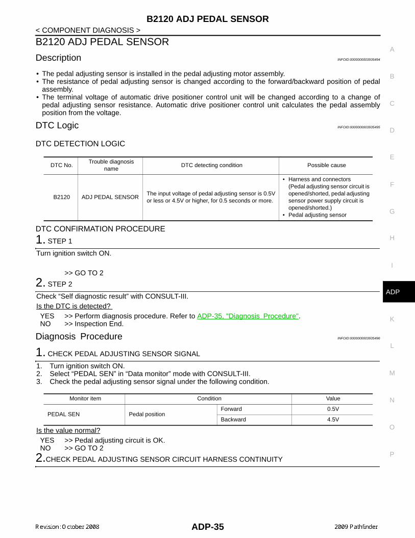
Description INFOID:0000000003935494
• The pedal adjusting sensor is installed in the pedal adjusting motor assembly.• The resistance of pedal adjusting sensor is changed according to the forward/backward position of pedal
assembly.• The terminal voltage of automatic drive positioner control unit will be changed according to a change of
pedal adjusting sensor resistance. Automatic drive positioner control unit calculates the pedal assemblyposition from the voltage.
DTC Logic INFOID:0000000003935495
DTC DETECTION LOGIC
DTC CONFIRMATION PROCEDURE
1. STEP 1
Turn ignition switch ON.
>> GO TO 2
2. STEP 2
Check “Self diagnostic result” with CONSULT-III.Is the DTC is detected? YES >> Perform diagnosis procedure. Refer to ADP-35, "Diagnosis Procedure".NO >> Inspection End.
Diagnosis Procedure INFOID:0000000003935496
1. CHECK PEDAL ADJUSTING SENSOR SIGNAL
1. Turn ignition switch ON.2. Select “PEDAL SEN” in “Data monitor” mode with CONSULT-III. 3. Check the pedal adjusting sensor signal under the following condition.
Is the value normal?YES >> Pedal adjusting circuit is OK.NO >> GO TO 2
2.CHECK PEDAL ADJUSTING SENSOR CIRCUIT HARNESS CONTINUITY
DTC No.Trouble diagnosis
nameDTC detecting condition Possible cause
B2120 ADJ PEDAL SENSORThe input voltage of pedal adjusting sensor is 0.5V or less or 4.5V or higher, for 0.5 seconds or more.
• Harness and connectors(Pedal adjusting sensor circuit is opened/shorted, pedal adjusting sensor power supply circuit is opened/shorted.)
• Pedal adjusting sensor
Monitor item Condition Value
PEDAL SEN Pedal positionForward 0.5V
Backward 4.5V
ADP-35

B2120 ADJ PEDAL SENSOR
< COMPONENT DIAGNOSIS >1. Disconnect automatic drive positioner control unit and pedaladjusting motor assembly. 2. Check continuity between automatic drive positioner connector
and pedal adjusting motor connector.
3. Check continuity between automatic drive positioner control unitconnector and ground.
Is the inspection result normal?YES >> Replace pedal adjusting motor assembly. Refer to BR-23, "Removal and Installation". NO >> Repair or replace harness.
Connector Terminal Connector TerminalContinuity
A B
Automatic drive positioner control unit: M33
8
Pedal adjust-ing motor as-sembly: E110
4 Yes
C
Automatic drive positioner control unit: M34
33 5 Yes
41 3 Yes
Connector Terminal
Ground
ContinuityA
Automatic drive positioner control unit: M33
8 No
B
Automatic drive positioner control unit: M34
33 No
41 No
LIIA2236E
ADP-36

B2126 DETENT SW
C
D
E
F
G
H
I
K
L
M
A
B
DP
N
O
P
< COMPONENT DIAGNOSIS >
A
B2126 DETENT SW
Description INFOID:0000000003935497
• Park position switch is installed on A/T device. It is turned OFF when the A/T selector lever is in P position.• The driver seat control unit judges that the A/T selector lever is in P position if continuity does not exist in this
circuit.
DTC Logic INFOID:0000000003935498
DTC DETECTION LOGIC
DTC CONFIRMATION PROCEDURE
1. STEP 1
Drive the vehicle at 7±4km/h or more.
>> GO TO 2
2. STEP 2
Check “Self diagnostic result” with CONSULT-III.Is the DTC detected? YES >> Perform diagnosis procedure. Refer to ADP-37, "Diagnosis Procedure".NO >> Inspection End.
Diagnosis Procedure INFOID:0000000003935499
1. CHECK DTC
Check “Self diagnostic result” for BCM with CONSULT-lll.Are other DTCs detected?YES >> Check The DTC.NO >> GO TO 2
2. CHECK DETENTION SWITCH SIGNAL
1. Turn ignition switch ON.2. Select “DETENT SW” in “Data Monitor” mode with CONSULT-lll.3. Check detention switch signal under the following condition.
Is the status normal?YES >> A/T device (park position switch) circuit is OK.NO >> GO TO 3
3. CHECK A/T DEVICE (PARK POSITION SWITCH) HARNESS
DTC No.Trouble diagnosis
nameDTC detecting condition Possible cause
B2126 DETENT SWA/T selector lever is in P position and the vehicle speed of 7±4km/h is detected.
• Harness and connectors(Park position switch circuit is opened/shorted.)
• Park position switch• Combination meter
(CAN communication )
Monitor item Condition Status
DETENT SW A/T selector leverP position OFF
Other than above ON
ADP-37

B2126 DETENT SW
< COMPONENT DIAGNOSIS >1. Turn ignition switch OFF.2. Disconnect A/T device and driver seat control unit.3. Check continuity between A/T device connector M158 terminal 4and driver seat control unit connector B203 terminal 21.
4. Check continuity between A/T device connector M158 terminal 4and ground.
Is the inspection result normal?YES >> GO TO 4NO >> Repair or replace harness.
4. CHECK PARK POSITION SWITCH
Check continuity between A/T device (park position switch) terminalsas follows.
Is the inspection result normal?YES >> GO TO 5NO >> Replace A/T device. Refer to TM-195, "Removal and
Installation".
5. CHECK INTERMITTENT INCIDENT
Refer to GI-49, "Intermittent Incident".Is the inspection result normal?YES >> Replace driver seat control unit. Refer to SE-25, "Exploded View".NO >> Repair or replace the malfunctioning part.
4 - 21 : Continuity should exist.
4 - Ground : Continuity should not exist.LIIA1774E
Terminals Condition Continuity
2 4P position Yes
Other than P position No
LIIA1775E
ADP-38

B2128 UART COMMUNICATION LINE
C
D
E
F
G
H
I
K
L
M
A
B
DP
N
O
P
< COMPONENT DIAGNOSIS >
A
B2128 UART COMMUNICATION LINE
Description INFOID:0000000003935500
Driver seat control unit performs UART communication with the automatic drive positioner control unit using 2communication lines, TX and RX line. Driver seat control unit receives the operation signals of pedal adjustingswitch, door mirror remote control switch, set switch and memory switch and the position signals of adjustablepedal sensor and door mirror sensor from the automatic drive positioner control unit and transmits the opera-tion request signal.
DTC Logic INFOID:0000000003935501
DTC DETECTION LOGIC
DTC CONFIRMATION PROCEDURE
1. STEP 1
Turn ignition switch ON.
>> GO TO 2
2. STEP 2
Operate pedal adjusting switch for more than 2 seconds.
>> GO TO 3
3. PROCEDURE 3
Check “Self diagnostic result” with CONSULT-III.Is the DTC detected? YES >> Perform diagnosis procedure. Refer to ADP-39, "Diagnosis Procedure".NO >> Inspection End.
Diagnosis Procedure INFOID:0000000003935502
1. CHECK UART COMMUNICATION LINE CONTINUITY
1. Turn ignition switch OFF.2. Disconnect driver seat control unit and automatic drive posi-
tioner control unit.3. Check continuity between driver seat control unit harness con-
nector and automatic drive positioner control unit harness con-nector.
4. Check continuity between driver seat control unit harness connector and ground.
DTC No. Trouble diagnosis name DTC detecting condition Possible cause
B2128 UART COMMThe communication between driver seat control unit and automatic drive positioner control unit is interrupt-ed for a period of time.
• UART communication line(UART communication line is open or shorted)
• Driver seat control unit• Automatic drive positioner
control unit
Driver seat control unit connector
TerminalAutomatic drive positioner
control unit connectorTerminal Continuity
B2021
M3310
Yes17 26
PIIA4598E
ADP-39

B2128 UART COMMUNICATION LINE
< COMPONENT DIAGNOSIS >Is the inspection result normal?YES >> Check intermittent incident. Refer to GI-49, "Intermittent Incident".NO >> Repair or replace harness.
Driver seat control unit con-nector
Terminal
Ground
Continuity
B2021
No17
ADP-40
POWER SUPPLY AND GROUND CIRCUIT
C
D
E
F
G
H
I
K
L
M
A
B
DP
N
O
P
< COMPONENT DIAGNOSIS >
A
POWER SUPPLY AND GROUND CIRCUITBCM
BCM : Diagnosis Procedure INFOID:0000000004428648
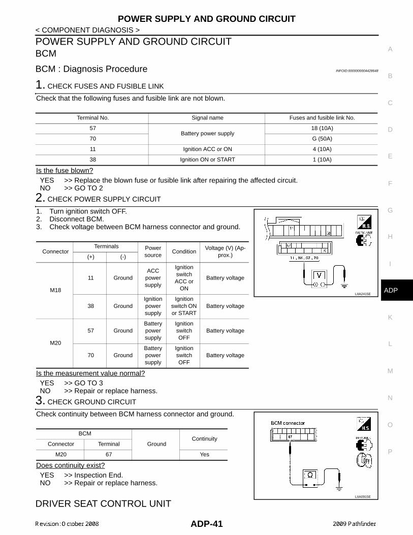
1. CHECK FUSES AND FUSIBLE LINK
Check that the following fuses and fusible link are not blown.
Is the fuse blown?YES >> Replace the blown fuse or fusible link after repairing the affected circuit.NO >> GO TO 2
2. CHECK POWER SUPPLY CIRCUIT
1. Turn ignition switch OFF.2. Disconnect BCM.3. Check voltage between BCM harness connector and ground.
Is the measurement value normal?YES >> GO TO 3NO >> Repair or replace harness.
3. CHECK GROUND CIRCUIT
Check continuity between BCM harness connector and ground.
Does continuity exist?YES >> Inspection End.NO >> Repair or replace harness.
DRIVER SEAT CONTROL UNIT
Terminal No. Signal name Fuses and fusible link No.
57Battery power supply
18 (10A)
70 G (50A)
11 Ignition ACC or ON 4 (10A)
38 Ignition ON or START 1 (10A)
ConnectorTerminals Power
sourceCondition
Voltage (V) (Ap-prox.)(+) (-)
M18
11 GroundACC
power supply
Ignition switch ACC or
ON
Battery voltage
38 GroundIgnition power supply
Ignition switch ON or START
Battery voltage
M20
57 GroundBattery power supply
Ignition switch OFF
Battery voltage
70 GroundBattery power supply
Ignition switch OFF
Battery voltage
LIIA2415E
BCM
GroundContinuity
Connector Terminal
M20 67 Yes
LIIA0915E
ADP-41

POWER SUPPLY AND GROUND CIRCUIT
< COMPONENT DIAGNOSIS >DRIVER SEAT CONTROL UNIT : Diagnosis Procedure INFOID:0000000003935505
NOTE:Do not disconnect the battery negative terminal and the driver seat control unit connector until DTC is con-firmed with CONSULT-III.
1. CHECK POWER SUPPLY CIRCUIT
1. Turn ignition switch OFF.2. Check voltage between driver seat control unit harness connec-
tor and ground.
Is the inspection result normal?YES >> GO TO 2.NO >> Check the following.
• Repair or replace harness between driver seat control unit and fuse block (J/B).• Circuit breaker.
2. CHECK GROUND CIRCUIT
Check continuity between the driver seat control unit harness con-nector and ground.
Is the inspection result normal?YES >> Driver seat control unit power supply and ground circuit
are OK.NO >> Repair or replace harness.
DRIVER SEAT CONTROL UNIT : Special Repair Requirement INFOID:0000000003935506
1. PERFORM ADDITIONAL SERVICE
Perform additional service when removing battery negative terminal.
>> Refer to Owner’s Manual.AUTOMATIC DRIVE POSITIONER CONTROL UNIT
AUTOMATIC DRIVE POSITIONER CONTROL UNIT : Diagnosis ProcedureINFOID:0000000003935507
NOTE:Do not disconnect the battery negative terminal and the driver seat control unit connector until DTC is con-firmed with CONSULT-III.
1. CHECK POWER SUPPLY CIRCUIT
Terminals
Power source
ConditionVoltage (V)(Approx.)
(+)
(–)Driver seat control unit connector
Terminal
B202 6
Ground
START power sup-
ply
Ignition switch START Battery
voltage
B20333 Battery
power sup-ply
Ignition switch OFF40
LIIA1897E
Driver seat control unitconnector
Terminal
Ground
Continuity
B202 32Yes
B203 48
PIIA4542E
ADP-42

POWER SUPPLY AND GROUND CIRCUIT
C
D
E
F
G
H
I
K
L
M
A
B
DP
N
O
P
< COMPONENT DIAGNOSIS >
A
1. Turn ignition switch OFF.2. Check voltage between automatic drive positioner control unit
harness connector and ground.
Is the inspection result normal?YES >> GO TO 2.NO >> Repair or replace harness.
2. CHECK GROUND CIRCUIT
Check continuity between the automatic drive positioner control unitharness connector and ground.
Is the inspection result normal?YES >> Automatic drive positioner control unit power supply and
ground circuit are OK.NO >> Repair or replace harness.
AUTOMATIC DRIVE POSITIONER CONTROL UNIT : Special Repair RequirementINFOID:0000000003935508
1.PERFORM ADDITIONAL SERVICE
Perform additional service when removing battery negative terminal.
>> Refer to Owner’s Manual.
Terminals
Voltage (V)(Approx.)
(+)
(–)Automatic drive positioner control unit connector
Terminal
M3334
Ground Battery voltage39 PIIA4543E
Automatic drive positioner control unit connector
Terminal
Ground
Continuity
M3340
Yes48
PIIA4544E
ADP-43

SLIDING SWITCH
< COMPONENT DIAGNOSIS >SLIDING SWITCH
Description INFOID:0000000003935509
Sliding switch is equipped to the power seat switch LH on the seat cushion trim. The operation signal is inputto the driver seat control unit when the sliding switch is operated.
Component Function Check INFOID:0000000003935510
1. CHECK FUNCTION
1. Select “SLIDE SW-FR”, “SLIDE SW-RR” in “Data monitor” mode with CONSULT-III. 2. Check sliding switch signal under the following conditions.
Is the indication normal?YES >> Inspection End.NO >> Perform diagnosis procedure. Refer to ADP-44, "Diagnosis Procedure".
Diagnosis Procedure INFOID:0000000003935511
1. CHECK SLIDING SWITCH SIGNAL
1. Turn ignition switch ON.2. Check voltage between driver seat control unit harness connec-
tor and ground.
Is the inspection result normal?YES >> GO TO 5NO >> GO TO 2
2. CHECK SLIDING SWITCH CIRCUIT
1. Turn ignition switch OFF.2. Disconnect driver seat control unit and power seat switch LH.3. Check continuity between driver seat control unit harness con-
nector and power seat switch LH harness connector.
Monitor item Condition Status
SLIDE SW-FR Sliding switch (forward)Operate ON
Release OFF
SLIDE SW-RR Sliding switch (backward)Operate ON
Release OFF
Driver seat control unit connector
TerminalsCondition
Voltage (V)(Approx.)(+) (–)
B202
11
GroundSliding switch
Operate (backward)
0
ReleaseBattery voltage
26
Operate (forward)
0
ReleaseBattery voltage
PIIA4577E
Driver seat control unit connector
TerminalPower seat switch
LH connectorTerminal Continuity
B202 (A)11
B208 (B)1
Yes26 5
ALJIA0308ZZ
ADP-44

SLIDING SWITCH
C
D
E
F
G
H
I
K
L
M
A
B
DP
N
O
P
< COMPONENT DIAGNOSIS >
A
4. Check continuity between driver seat control unit harness connector and ground.
Is the inspection result normal?YES >> GO TO 3NO >> Repair or replace harness.
3. CHECK DRIVER SEAT CONTROL UNIT OUTPUT
1. Connect the driver seat control unit.2. Turn ignition switch ON.3. Check voltage between driver seat control unit harness connec-
tor and ground.
Is the inspection result normal?YES >> GO TO 4NO >> Replace driver seat control unit. Refer to SE-25, "Exploded View".
4. CHECK SLIDING SWITCH
Refer to ADP-45, "Component Inspection".Is the inspection result normal?YES >> GO TO 5NO >> Replace power seat switch LH. Refer to SE-25, "Exploded View".
5. CHECK INTERMITTENT INCIDENT
Refer to GI-49, "Intermittent Incident".Is the inspection result normal?YES >> Replace driver seat control unit. Refer to SE-25, "Exploded View".NO >> Repair or replace malfunctioning part.
Component Inspection INFOID:0000000003935512
1. CHECK SLIDING SWITCH
1. Turn ignition switch OFF.2. Disconnect power seat switch LH.3. Check continuity between power seat switch LH terminals.
Is the inspection result normal?YES >> Inspection End.NO >> Replace power seat switch LH. Refer to SE-25, "Exploded View".
Driver seat control unit connector
Terminal
Ground
Continuity
B202 (A)11
No26
Driver seat control unit connector
Terminals Voltage (V)(Approx.)(+) (–)
B20211
Ground Battery voltage26
PIIA4577E
TerminalCondition Continuity
Power seat switch LH
7
1 Sliding switch (backward)Operate Yes
Release No
5 Sliding switch (forward)Operate Yes
Release No ALJIA0309ZZ
ADP-45

RECLINING SWITCH
< COMPONENT DIAGNOSIS >RECLINING SWITCH
Description INFOID:0000000003935513
Reclining switch is equipped to the power seat switch LH on the seat cushion trim. The operation signal isinput to the driver seat control unit when the reclining switch is operated.
Component Function Check INFOID:0000000003935514
1. CHECK FUNCTION
1. Select “RECLN SW-FR”, “RECLN SW-RR” in “Data monitor” mode with CONSULT-III. 2. Check reclining switch signal under the following conditions.
Is the indication normal?YES >> Inspection End.NO >> Perform diagnosis procedure. Refer to ADP-46, "Diagnosis Procedure".
Diagnosis Procedure INFOID:0000000003935515
1. CHECK RECLINING SWITCH SIGNAL
1. Turn ignition switch ON.2. Check voltage between driver seat control unit harness connec-
tor and ground.
Is the inspection result normal?YES >> GO TO 5NO >> GO TO 2
2. CHECK RECLINING SWITCH CIRCUIT
1. Turn ignition switch OFF.2. Disconnect driver seat control unit and power seat switch LH.3. Check continuity between driver seat control unit harness con-
nector and power seat switch LH harness connector.
4. Check continuity between driver seat control unit harness con-nector and ground.
Monitor item Condition Status
RECLN SW-FR Reclining switch (forward)Operate ON
Release OFF
RECLN SW-RR Reclining switch (backward)Operate ON
Release OFF
Driver seat control unit connector
Terminals Condition
Voltage (V) (Approx.)(+) (–)
B202
12
GroundReclining
switch
Operate (forward)
0
Release Battery voltage
27
Operate (backward)
0
Release Battery voltage
PIIA4580E
Driver seat control unit connector
TerminalPower seat switch
LH connectorTerminal Continuity
B202 (A)12
B208 (B)3
Yes27 4
ALJIA0310ZZ
ADP-46

RECLINING SWITCH
C
D
E
F
G
H
I
K
L
M
A
B
DP
N
O
P
< COMPONENT DIAGNOSIS >
A
Is the inspection result normal?YES >> GO TO 3NO >> Repair or replace harness.
3. CHECK DRIVER SEAT CONTROL UNIT OUTPUT
1. Connect the driver seat control unit connector.2. Turn ignition switch ON.3. Check voltage between driver seat control unit harness connec-
tor and ground.
Is the inspection result normal?YES >> GO TO 4NO >> Replace driver seat control unit. Refer to SE-25, "Exploded View".
4. CHECK RECLINING SWITCH
Refer to ADP-47, "Component Inspection".Is the inspection result normal?YES >> GO TO 5NO >> Replace power seat switch LH. Refer to SE-25, "Exploded View".
5. CHECK INTERMITTENT INCIDENT
Refer to GI-49, "Intermittent Incident".Is the inspection result normal?YES >> Replace driver seat control unit. Refer to SE-25, "Exploded View".NO >> Repair or replace the malfunctioning part. Refer to SE-25, "Exploded View".
Component Inspection INFOID:0000000003935516
1. CHECK RECLINING SWITCH
1. Turn ignition switch OFF.2. Disconnect power seat switch LH.3. Check continuity between power seat switch LH terminals.
Is the inspection result normal?YES >> Inspection End.NO >> Replace power seat switch LH. Refer to SE-25, "Exploded View".
Driver seat control unitconnector
Terminal
Ground
Continuity
B202 (A)12
No27
Driver seat control unit connector
Terminals Voltage (V) (Approx.)(+) (–)
B20212
Ground Battery voltage27
PIIA4580E
TerminalsCondition Continuity
Power seat switch LH
7
3Reclining switch (backward)
Operate Yes
Release No
4Reclining switch (forward)
Operate Yes
Release No ALJIA0311ZZ
ADP-47
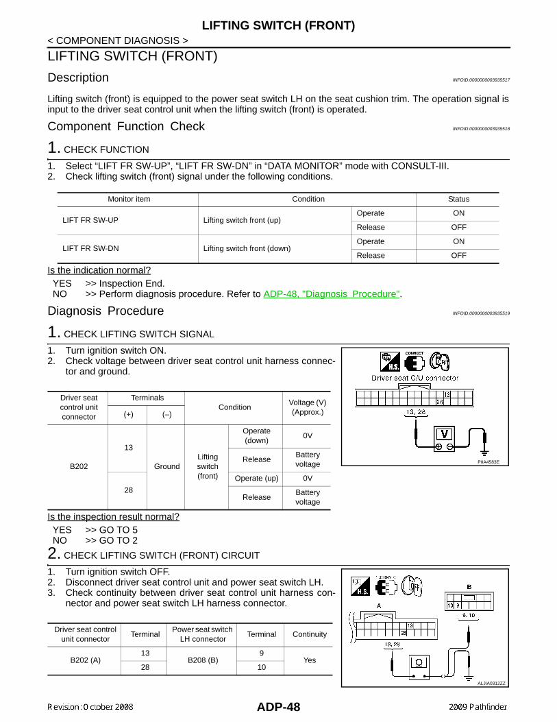
LIFTING SWITCH (FRONT)
< COMPONENT DIAGNOSIS >LIFTING SWITCH (FRONT)
Description INFOID:0000000003935517
Lifting switch (front) is equipped to the power seat switch LH on the seat cushion trim. The operation signal isinput to the driver seat control unit when the lifting switch (front) is operated.
Component Function Check INFOID:0000000003935518
1. CHECK FUNCTION
1. Select “LIFT FR SW-UP”, “LIFT FR SW-DN” in “DATA MONITOR” mode with CONSULT-III.2. Check lifting switch (front) signal under the following conditions.
Is the indication normal?YES >> Inspection End.NO >> Perform diagnosis procedure. Refer to ADP-48, "Diagnosis Procedure".
Diagnosis Procedure INFOID:0000000003935519
1. CHECK LIFTING SWITCH SIGNAL
1. Turn ignition switch ON.2. Check voltage between driver seat control unit harness connec-
tor and ground.
Is the inspection result normal?YES >> GO TO 5NO >> GO TO 2
2. CHECK LIFTING SWITCH (FRONT) CIRCUIT
1. Turn ignition switch OFF.2. Disconnect driver seat control unit and power seat switch LH.3. Check continuity between driver seat control unit harness con-
nector and power seat switch LH harness connector.
Monitor item Condition Status
LIFT FR SW-UP Lifting switch front (up)Operate ON
Release OFF
LIFT FR SW-DN Lifting switch front (down)Operate ON
Release OFF
Driver seat control unit connector
Terminals Condition
Voltage (V) (Approx.)(+) (–)
B202
13
GroundLifting switch (front)
Operate (down)
0V
ReleaseBattery voltage
28
Operate (up) 0V
ReleaseBattery voltage
PIIA4583E
Driver seat control unit connector
TerminalPower seat switch
LH connectorTerminal Continuity
B202 (A)13
B208 (B)9
Yes28 10
ALJIA0312ZZ
ADP-48

LIFTING SWITCH (FRONT)
C
D
E
F
G
H
I
K
L
M
A
B
DP
N
O
P
< COMPONENT DIAGNOSIS >
A
4. Check continuity between driver seat control unit harness connector and ground.
Is the inspection result normal?YES >> GO TO 3NO >> Repair or replace harness.
3. CHECK DRIVER SEAT CONTROL UNIT OUTPUT
1. Connect the driver seat control unit.2. Turn ignition switch ON.3. Check voltage between driver seat control unit harness connec-
tor and ground.
Is the inspection result normal?YES >> GO TO 4NO >> Replace driver seat control unit. Refer to SE-25, "Exploded View".
4. CHECK LIFTING SWITCH (FRONT)
Refer to ADP-49, "Component Inspection".Is the inspection result normal?YES >> GO TO 5NO >> Replace power seat switch LH. Refer to SE-25, "Exploded View".
5. CHECK INTERMITTENT INCIDENT
Refer to GI-49, "Intermittent Incident".Is the inspection result normal?YES >> Replace driver seat control unit. Refer to SE-25, "Exploded View".NO >> Repair or replace the malfunctioning part.
Component Inspection INFOID:0000000003935520
1. CHECK LIFTING SWITCH (FRONT)
1. Turn ignition switch OFF.2. Disconnect power seat switch LH.3. Check continuity between power seat switch LH terminals.
Is the inspection result normal?YES >> Inspection End.NO >> Replace power seat switch LH. Refer to SE-25, "Exploded View".
Driver seat control unitconnector
Terminal
Ground
Continuity
B202 (A)13
No28
Driver seat control unitconnector
Terminals Voltage (V) (Approx.)(+) (–)
B20213
Ground Battery voltage28
PIIA4583E
TerminalCondition Continuity
Power seat switch LH
7
9 Lifting switch front (down)Operate Yes
Release No
10 Lifting switch front (up)Operate Yes
Release NoALJIA0313ZZ
ADP-49

LIFTING SWITCH (REAR)
< COMPONENT DIAGNOSIS >LIFTING SWITCH (REAR)
Description INFOID:0000000003935521
Lifting switch (rear) is equipped to the power seat switch LH on the seat cushion trim. The operation signal isinput to the driver seat control unit when the lifting switch (rear) is operated.
Component Function Check INFOID:0000000003935522
1. CHECK FUNCTION
1. Select “LIFT RR SW-UP”, “LIFT RR SW-DN” in “Data monitor” mode with CONSULT-III. 2. Check lifting switch (rear) signal under the following conditions.
Is the indication normal?YES >> Inspection End.NO >> Perform diagnosis procedure. Refer to ADP-50, "Diagnosis Procedure".
Diagnosis Procedure INFOID:0000000003935523
1. CHECK LIFTING SWITCH (REAR) SIGNAL
1. Turn ignition switch ON.2. Check voltage between driver seat control unit harness connec-
tor and ground.
Is the inspection result normal?YES >> GO TO 5NO >> GO TO 2
2. CHECK LIFTING SWITCH (REAR) CIRCUIT
1. Turn ignition switch OFF.2. Disconnect driver seat control unit and power seat switch LH.3. Check continuity between driver seat control unit harness con-
nector and power seat switch LH harness connector.
4. Check continuity between driver seat control unit harness con-nector and ground.
Monitor item Condition Status
LIFT RR SW-UP Lifting switch rear (up)Operate ON
Release OFF
LIFT RR SW-DN Lifting switch rear (down)Operate ON
Release OFF
Driver seat control unit connector
Terminals Condition
Voltage (V) (Approx.)(+) (–)
B202
14
GroundLifting switch(rear)
Operate (down) 0
Release Battery voltage
29Operate (up) 0
Release Battery voltage
PIIA4586E
Driver seat control unit connector
TerminalPower sear switch
LH connectorTerminal Continuity
B202 (A)14
B208 (B)2
Yes29 6
ALJIA0314ZZ
ADP-50

LIFTING SWITCH (REAR)
C
D
E
F
G
H
I
K
L
M
A
B
DP
N
O
P
< COMPONENT DIAGNOSIS >
A
Is the inspection result normal?YES >> GO TO 3NO >> Repair or replace harness.
3. CHECK DRIVER SEAT CONTROL UNIT OUTPUT
1. Connect the driver seat control unit.2. Turn ignition switch ON.3. Check voltage between driver seat control unit harness connec-
tor and ground.
Is the inspection result normal?YES >> GO TO 4NO >> Replace driver seat control unit. Refer to SE-25, "Exploded View".
4. CHECK LIFTING SWITCH (REAR)
Refer to ADP-51, "Component Inspection".Is the inspection result normal?YES >> GO TO 5NO >> Replace power seat switch LH. Refer to SE-25, "Exploded View".
5. CHECK INTERMITTENT INCIDENT
Refer to GI-49, "Intermittent Incident".Is the inspection result normal?YES >> Replace driver seat control unit. Refer to SE-25, "Exploded View".NO >> Repair or replace the malfunctioning part.
Component Inspection INFOID:0000000003935524
1. CHECK LIFTING SWITCH (REAR)
1. Turn ignition switch OFF.2. Disconnect power seat switch LH.3. Check continuity between power seat switch LH terminals.
Is the inspection result normal?YES >> Inspection End.NO >> Replace power seat switch LH. Refer to SE-25, "Exploded View".
Driver seat control unitconnector
Terminal
Ground
Continuity
B202 (A)14
No29
Driver seat control unit connector
Terminals Voltage (V) (Approx.)(+) (–)
B20214
Ground Battery voltage29
PIIA4586E
TerminalCondition Continuity
Power seat switch LH
7
2 Lifting switch rear (up)Operate Yes
Release No
6 Lifting switch rear (down)Operate Yes
Release NoALJIA0315ZZ
ADP-51

PEDAL ADJUSTING SWITCH
< COMPONENT DIAGNOSIS >PEDAL ADJUSTING SWITCH
Description INFOID:0000000003935525
Pedal adjusting switch is on the instrument panel. The operation signal is input to the driver seat control unitwhen the pedal adjusting switch is operated. The pedal adjusting switch signal is sent to the automatic drivepositioner control unit via UART communication.
Component Function Check INFOID:0000000003935526
1. CHECK FUNCTION
1. Select “PEDAL SW-FR”, “PEDAL SW-RR” in “Data monitor” mode with CONSULT-III. 2. Check pedal adjusting switch signal under the following conditions.
Is the indication normal?YES >> Inspection End.NO >> Perform diagnosis procedure. Refer to ADP-52, "Diagnosis Procedure".
Diagnosis Procedure INFOID:0000000003935527
1. CHECK PEDAL ADJUSTING SWITCH SIGNAL
1. Turn ignition switch ON.2. Check voltage between driver seat control unit harness connec-
tor and ground.
Is the inspection result normal?YES >> GO TO 5NO >> GO TO 2
2. CHECK PEDAL ADJUSTING SWITCH CIRCUIT
Monitor item Condition Status
PEDAL SW-FR Pedal adjusting switch (forward)Operate ON
Release OFF
PEDAL SW-RR Pedal adjusting switch (backward)Operate ON
Release OFF
Driver seat control unit connector
Terminals Condition
Voltage (V) (Approx.)(+) (–)
B202
15
GroundPedal ad-
justing switch
Operate (backward)
0
ReleaseBattery voltage
30
Operate (forward)
0
ReleaseBattery voltage
PIIA4591E
ADP-52

PEDAL ADJUSTING SWITCH
C
D
E
F
G
H
I
K
L
M
A
B
DP
N
O
P
< COMPONENT DIAGNOSIS >
A
1. Turn ignition switch OFF.2. Disconnect driver seat control unit and pedal adjusting switch.3. Check continuity between driver seat control unit harness con-
nector and pedal adjusting switch harness connector.
4. Check continuity between driver seat control unit harness con-nector and ground.
Is the inspection result normal?YES >> GO TO 3NO >> Repair or replace harness.
3. CHECK DRIVER SEAT CONTROL UNIT OUTPUT
1. Connect the driver seat control unit.2. Turn ignition switch ON.3. Check voltage between driver seat control unit harness connec-
tor and ground.
Is the inspection result normal?YES >> GO TO 4NO >> Replace driver seat control unit. Refer to SE-25, "Exploded View".
4. CHECK PEDAL ADJUSTING SWITCH
Refer to ADP-54, "Component Inspection".Is the inspection result normal?YES >> GO TO 5NO >> Replace pedal adjusting switch.
5. CHECK PEDAL ADJUSTING SWITCH GROUND CIRCUIT
Check continuity between pedal adjusting switch connector M96 ter-minal 1 and ground.
Is the inspection result normal?YES >> GO TO 6NO >> Replace or replace harness.
6. CHECK INTERMITTENT INCIDENT
Driver seatcontrol unit connector
TerminalPedal adjusting
switch connectorTerminal Continuity
B20215
M962
Yes30 3
Driver seat control unit connector
Terminal
Ground
Continuity
B20215
No30
LIIA0726E
Driver seat control unit connector
Terminals Voltage (V) (Approx.)(+) (–)
B20215
Ground Battery voltage30
PIIA4591E
1 - Ground : Continuity should exist.
LIIA1015E
ADP-53

PEDAL ADJUSTING SWITCH
< COMPONENT DIAGNOSIS >Refer to GI-49, "Intermittent Incident".Is the inspection result normal?YES >> Replace automatic drive positioner control unit. Refer to ADP-159, "Removal and Installation".NO >> Repair or replace the malfunctioning part.Component Inspection INFOID:0000000003935528
1. CHECK PEDAL ADJUSTING SWITCH
1. Turn ignition switch OFF.2. Disconnect pedal adjusting switch.3. Check continuity between pedal adjusting switch terminals.
Is the inspection result normal?YES >> Inspection End.NO >> Replace pedal adjusting switch.
TerminalCondition Continuity
Pedal adjusting switch
1
2Pedal adjusting switch (backward)
Operate Yes
Release No
3Pedal adjusting switch (forward)
Operate Yes
Release NoLIIA1014E
ADP-54

SEAT MEMORY SWITCH
C
D
E
F
G
H
I
K
L
M
A
B
DP
N
O
P
< COMPONENT DIAGNOSIS >
A
SEAT MEMORY SWITCH
Description INFOID:0000000003935529
Memory switch is equipped on the seat memory switch installed to the front door LH trim. The operation signalis input to the automatic drive positioner control unit when the memory switch is operated.
Component Function Check INFOID:0000000003935530
1. CHECK FUNCTION
1. Select “MEMORY SW 1”, “MEMORY SW 2”, "SET SW" in “Data monitor” mode with CONSULT-III. 2. Check seat memory switch signal under the following conditions.
Is the indication normal?YES >> Inspection End.NO >> Perform diagnosis procedure. Refer to ADP-55, "Diagnosis Procedure".
Diagnosis Procedure INFOID:0000000003935531
1. CHECK MEMORY SWITCH CIRCUIT
1. Turn ignition switch OFF.2. Disconnect automatic drive positioner control unit and seat
memory switch.3. Check continuity between automatic drive positioner control unit
harness connector and seat memory switch harness connector.
4. Check continuity between automatic drive positioner control unit harness connector and ground.
Is the inspection result normal?YES >> GO TO 2NO >> Repair or replace harness.
2. CHECK MEMORY SWITCH GROUND CIRCUIT
Monitor item Condition Status
MEMORY SW1 Memory switch 1Push ON
Release OFF
MEMORY SW2 Memory switch 2Push ON
Release OFF
SET SW Set switch Push ON
Release OFF
Automatic drive positioner control
unit connectorTerminal
Seat memory switch connector
Terminal Continuity
M33
9
D5
1
Yes24 3
25 2
Automatic drive positionercontrol unit connector
Terminal
Ground
Continuity
M33
9
No24
25
PIIA4576E
ADP-55

SEAT MEMORY SWITCH
< COMPONENT DIAGNOSIS >Check continuity between seat memory switch harness connectorand ground.Is the inspection result normal?YES >> GO TO 3NO >> Repair or replace harness.
3. CHECK SEAT MEMORY SWITCH
Refer to ADP-56, "Component Inspection".Is the inspection result normal?YES >> GO TO 4NO >> Replace seat memory switch. Refer to INT-14, "Removal and Installation".
4. CHECK INTERMITTENT INCIDENT
Refer to GI-49, "Intermittent Incident".Is the inspection result normal?YES >> Replace automatic drive positioner control unit. Refer to ADP-159, "Removal and Installation".NO >> Repair or replace the malfunctioning part.
Component Inspection INFOID:0000000003935532
1. CHECK SEAT MEMORY SWITCH
1. Turn ignition switch OFF.2. Disconnect seat memory switch.3. Check continuity between seat memory switch terminals.
Is the inspection result normal?YES >> Inspection End.NO >> Replace seat memory switch.
Seat memory switchconnector
TerminalGround
Continuity
D5 4 Yes
PIIA4821E
TerminalCondition Continuity
Seat memory switch
4
1 Memory switch 1Push Yes
Release No
2 Memory switch 2Push Yes
Release No
3 Set switchPush Yes
Release No
LIIA1020E
A D P - 5 6

DOOR MIRROR REMOTE CONTROL SWITCH
C
D
E
F
G
H
I
K
L
M
A
B
DP
N
O
P
< COMPONENT DIAGNOSIS >
A
DOOR MIRROR REMOTE CONTROL SWITCHCHANGEOVER SWITCH
CHANGEOVER SWITCH : Description INFOID:0000000003935533
Changeover switch is integrated into door mirror remote control switch.Changeover switch has three positions (L, N and R).It changes door mirror motor operation by transmitting control signal to automatic drive positioner control unit.
CHANGEOVER SWITCH : Component Function Check INFOID:0000000003935534
1. CHECK CHANGEOVER SWITCH FUNCTION
Check the operation on “MIR CHNG SW-R” or “MIR CHNG SW-L” in “DATA MONITOR” mode with CON-SULT-III.Refer to ADP-25, "CONSULT-III Function".Is the inspection result normal?YES >> Changeover switch function is OK.NO >> Refer to ADP-57, "CHANGEOVER SWITCH : Diagnosis Procedure".
CHANGEOVER SWITCH : Diagnosis Procedure INFOID:0000000003935535
1. CHECK CHANGEOVER SWITCH SIGNAL
1. Turn ignition switch ON.2. Check voltage between automatic drive positioner control unit
connector and ground.
Is the inspection result normal?YES >> GO TO 6NO >> GO TO 2
2. CHECK HARNESS CONTINUITY
1. Turn ignition switch OFF.2. Disconnect automatic drive positioner control unit and door mir-
ror remote control switch.3. Check continuity between automatic drive positioner control unit
connector and door mirror remote control switch connector.
4. Check continuity between automatic drive positioner control unit connector and ground.
Terminals
Change over switch condition
Voltage (V)(Approx.)
(+)
(-)Automatic drive positioner control
unit connectorTerminal
M33
2
Ground
RIGHT 0
Other than above 5
18LEFT 0
Other than above 5
PIIA4767E
Automatic drive positioner control
unit connectorTerminal
Door mirror re-mote control
switch connectorTerminal Continuity
M332
M1633
Yes18 2 LIIA1821E
ADP-57

DOOR MIRROR REMOTE CONTROL SWITCH
< COMPONENT DIAGNOSIS >Is the inspection result normal?YES >> GO TO 3NO >> Repair or replace harness.
3. CHECK DOOR MIRROR REMOTE CONTROL SWITCH GROUND CIRCUIT
Check continuity between door mirror remote control switch connec-tor and ground.
Is the inspection result normal?YES >> GO TO 4NO >> Repair or replace harness.
4. CHECK AUTOMATIC DRIVE POSITIONER CONTROL UNIT OUTPUT SIGNAL
1. Connect automatic drive positioner control unit.2. Turn ignition switch ON.3. Check voltage between automatic drive positioner control unit
connector and ground.
Is the inspection result normal?YES >> GO TO 5.NO >> Replace automatic drive positioner control unit. Refer to ADP-159, "Removal and Installation".
5. CHECK CHANGEOVER SWITCH
Check changeover switch.Refer to ADP-58, "CHANGEOVER SWITCH : Component Inspection".Is the inspection result normal?YES >> Refer to GI-49, "Intermittent Incident".NO >> Replace door mirror remote control switch. Refer to INT-14, "Removal and Installation".
6. CHECK INTERMITTENT INCIDENT
Check intermittent incident.Refer to GI-49, "Intermittent Incident".Is the inspection result normal?YES >> Replace automatic drive positioner control unit. Refer to ADP-159, "Removal and Installation".NO >> Repair or replace the malfunctioning parts.
CHANGEOVER SWITCH : Component Inspection INFOID:0000000003935536
1. CHECK CHANGEOVER SWITCH
Automatic drive positioner control unit connector
Terminal
Ground
Continuity
M332
No18
Door mirror remote control switch connector
TerminalGround
Continuity
M163 13 Yes
LIIA1825E
Terminals
Voltage (V)(Approx.)
(+)
(-)Automatic drive positioner control unit connector
Terminal
M332
Ground 518
PIIA4767E
ADP-58

DOOR MIRROR REMOTE CONTROL SWITCH
C
D
E
F
G
H
I
K
L
M
A
B
DP
N
O
P
< COMPONENT DIAGNOSIS >
A
Check door mirror remote control switch.
Is the inspection result normal?YES >> Inspection End.NO >> Replace door mirror remote control switch. Refer to ADP-161, "Removal and Installation".
MIRROR SWITCH
MIRROR SWITCH : Description INFOID:0000000003935537
It operates angle of the door mirror face.It transmits mirror face adjust operation to automatic drive positioner control unit.
MIRROR SWITCH : Component Function Check INFOID:0000000003935538
1. CHECK MIRROR SWITCH FUNCTION
Check the operation on “MIR CON SW–UP/DN” and “MIR CON SW–RH/LH” in “DATA MONITOR” modewith CONSULT-III.Refer to ADP-25, "CONSULT-III Function".Is the inspection result normal?YES >> Mirror switch function is OK.NO >> Refer to ADP-59, "MIRROR SWITCH : Diagnosis Procedure".
MIRROR SWITCH : Diagnosis Procedure INFOID:0000000003935539
1. CHECK MIRROR SWITCH FUNCTION
1. Turn ignition switch ON.2. Check voltage between automatic drive positioner control unit
connector and ground.
Is the inspection result normal?YES >> GO TO 6NO >> GO TO 2
2. CHECK HARNESS CONTINUITY
Terminal Change over switch condition
ContinuityDoor mirror remote control switch
2
13
LEFT Yes
Other than above No
3RIGHT Yes
Other than above No
LIIA2052E
Terminals
Mirror switchCondition
Voltage (V)(Approx.)
(+)
(–)Automatic drive positioner control
unit connectorTerminal
M33
3
Ground
UP 0
Other than above 5
4LEFT 0
Other than above 5
19DOWN 0
Other than above 5
20RIGHT 0
Other than above 5
PIIA4771E
ADP-59

DOOR MIRROR REMOTE CONTROL SWITCH
< COMPONENT DIAGNOSIS >1. Turn ignition switch OFF.2. Disconnect automatic drive positioner control unit and door mir-ror remote control switch.3. Check continuity between automatic drive positioner control unit
connector and door mirror remote control switch connector.
4. Check continuity between automatic drive positioner control unit connector and ground.
Is the inspection result normal?YES >> GO TO 3NO >> Repair or replace harness.
3. CHECK DOOR MIRROR REMOTE CONTROL SWITCH GROUND CIRCUIT
Check continuity between door mirror remote control switch connec-tor and ground.
Is the inspection result normal?YES >> GO TO 4NO >> Repair or replace harness.
4. CHECK AUTOMATIC DRIVE POSITIONER CONTROL UNIT OUTPUT SIGNAL
1. Connect automatic drive positioner control unit.2. Turn ignition switch ON.3. Check voltage between automatic drive positioner control unit
and ground.
Is the inspection result normal?
Automatic drive positioner control
unit connectorTerminal
Door mirror remote control switch con-
nectorTerminal Continuity
M33
3
M163
6
Yes4 5
19 14
20 4
Automatic drive positioner control unit connector
Terminal
Ground
Continuity
M33
3
No4
19
20
LIIA1823E
Door mirror remote control switch connector
TerminalGround
Continuity
M163 13 Yes
LIIA1825E
Terminals
Voltage (V)(Approx.)
(+)
(-)Automatic drive positioner control unit connector
Terminal
M33
3
Ground 54
19
20
PIIA4771E
ADP-60

DOOR MIRROR REMOTE CONTROL SWITCH
C
D
E
F
G
H
I
K
L
M
A
B
DP
N
O
P
< COMPONENT DIAGNOSIS >
A
YES >> GO TO 5NO >> Replace automatic drive positioner control unit. Refer to ADP-159, "Removal and Installation".
5. CHECK MIRROR SWITCH
Check mirror switch.Refer to ADP-61, "MIRROR SWITCH : Component Inspection".Is the inspection result normal?YES >> Refer to GI-49, "Intermittent Incident".NO >> Replace door mirror remote control switch. Refer to ADP-161, "Removal and Installation".
6. CHECK INTERMITTENT INCIDENT
Check intermittent incident.Refer to GI-49, "Intermittent Incident".Is the inspection result normal?YES >> Replace automatic drive positioner control unit. Refer to ADP-159, "Removal and Installation".NO >> Repair or replace the malfunctioning parts.
MIRROR SWITCH : Component Inspection INFOID:0000000003935540
1. CHECK MIRROR SWITCH
Check door mirror remote control switch.
Is the inspection result normal?YES >> Inspection End.NO >> Replace door mirror remote control switch. Refer to ADP-161, "Removal and Installation".
Terminal
Mirror switch condition ContinuityDoor mirror remote control switch
4
13
RIGHT Yes
Other than above No
5LEFT Yes
Other than above No
6UP Yes
Other than above No
14DOWN Yes
Other than above No
LIIA2053E
ADP-61

POWER SEAT SWITCH GROUND CIRCUIT
< COMPONENT DIAGNOSIS >POWER SEAT SWITCH GROUND CIRCUIT
Diagnosis Procedure INFOID:0000000003935541
1. CHECK POWER SEAT SWITCH LH GROUND CIRCUIT
1. Turn ignition switch OFF.2. Disconnect power seat switch LH.3. Check continuity between power seat switch LH connector and
ground.
Is the inspection result normal?YES >> Check intermittent incident. Refer to GI-49, "Intermittent
Incident".NO >> Repair or replace harness.
Power seat switch LH connector
TerminalGround
Continuity
B208 7 Yes
ALJIA0316ZZ
ADP-62

DETENTION SWITCH
C
D
E
F
G
H
I
K
L
M
A
B
DP
N
O
P
< COMPONENT DIAGNOSIS >
A
DETENTION SWITCH
Description INFOID:0000000003935542
Park position switch is installed on A/T device. It is turned OFF when the A/T selector lever is in P position.The driver seat control unit judges that the A/T selector lever is in P position if continuity does not exist in thiscircuit.
Component Function Check INFOID:0000000003935543
1. CHECK FUNCTION
1. Select “DETENT SW” signal in “Data monitor” mode with CONSULT-III. 2. Check park position switch signal under the following conditions.
Is the indication normal?YES >> Inspection End.NO >> Perform diagnosis procedure. Refer to ADP-63, "Diagnosis Procedure".
Diagnosis Procedure INFOID:0000000003935544
1. CHECK DTC WITH “BCM”
Check “Self Diagnostic Result” for BCM with CONSULT-lll.Is any other DTC detected?YES >> Check the DTC. NO >> GO TO 2
2. CHECK PARK POSITION SWITCH INPUT SIGNAL
1. Turn ignition switch ON.2. Mechanical key must be removed from the key switch.3. Check voltage between driver seat control unit harness connec-
tor and ground.
Is the inspection result normal?YES >> GO TO 4NO >> GO TO 3
3. CHECK PARK POSITION SWITCH CIRCUIT
Monitor item Condition Status
DETENT SW A/T selector lever
P position OFF
Other than above
ON
Driver seat control unit connector
TerminalCondition
Voltage (V)(Approx.)(+) (-)
B202 21 GroundA/T selec-tor lever
P positionBattery volt-
age
Other than above
0VLIIA2238E
ADP-63

DETENTION SWITCH
< COMPONENT DIAGNOSIS >1. Turn ignition switch OFF.2. Disconnect driver seat control unit and A/T device.3. Check continuity between driver seat control unit harness con-nector and A/T device harness connector.
4. Check continuity between A/T device harness connector andground.
Is the inspection result normal?YES >> GO TO 4NO >> Repair or replace harness.
4. CHECK INTERMITTENT INCIDENT
Refer to GI-49, "Intermittent Incident".Is the inspection result normal?YES >> Replace driver seat control unit. Refer to SE-25, "Exploded View".NO >> Repair or replace the malfunctioning part.
Driver seat control unit A/T deviceContinuity
Connector Terminal Connector Terminal
B202 21 M158 4 Yes
A/T device
GroundContinuity
Connector Terminal
M158 4 No
LIIA1774E
ADP-64

FRONT DOOR SWITCH (DRIVER SIDE)
C
D
E
F
G
H
I
K
L
M
A
B
DP
N
O
P
< COMPONENT DIAGNOSIS >
A
FRONT DOOR SWITCH (DRIVER SIDE)
Description INFOID:0000000003935545
Detects front door LH open/close condition.
Component Function Check INFOID:0000000003935546
1. CHECK FUNCTION
1. Select “DOOR SW-DR” in “Data monitor” mode with CONSULT-III.2. Check the front door switch LH signal under the following conditions.
Is the inspection result normal?YES >> Inspection End.NO >> Perform diagnosis procedure. Refer to ADP-65, "Diagnosis Procedure".
Diagnosis Procedure INFOID:0000000003935547
1. CHECK FRONT DOOR SWITCH LH CIRCUIT
1. Disconnect BCM.2. Check continuity between BCM connector and front door switch
LH connector.
3. Check continuity between BCM connector and ground.
Is the inspection result normal?YES >> GO TO 2NO >> Repair or replace harness.
2. CHECK FRONT DOOR SWITCH LH
Refer to ADP-65, "Component Inspection".Is the inspection result normal?YES >> GO TO 3NO >> Replace front door switch LH.
3. CHECK INTERMITTENT INCIDENT
Refer to GI-49, "Intermittent Incident".Is the inspection result normal?YES >> Replace BCM. Refer to BCS-59, "Removal and Installation".NO >> Repair or replace the malfunctioning part.
Component Inspection INFOID:0000000003935548
1. CHECK FRONT DOOR SWITCH LH
Monitor item Condition Status
DOOR SW-DR Front door switch LHOpen ON
Close OFF
BCM connector TerminalFront door switch
LH connectorTerminal Continuity
M19 47 B8 2 Yes
BCM connector TerminalGround
Continuity
M19 47 No
LIIA1027E
ADP-65
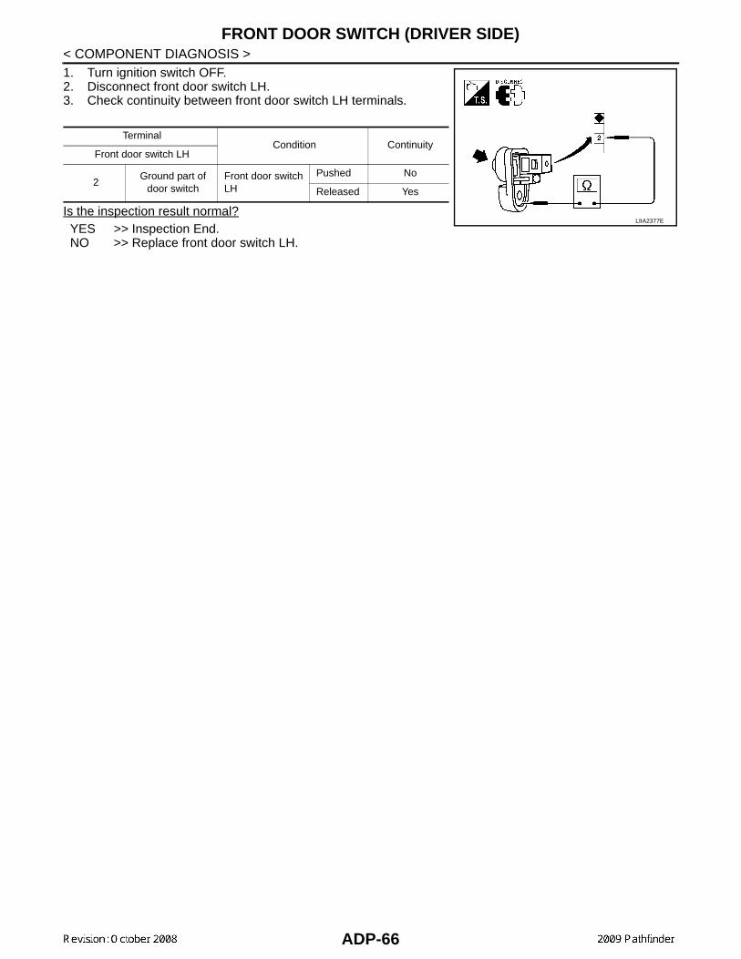
FRONT DOOR SWITCH (DRIVER SIDE)
< COMPONENT DIAGNOSIS >1. Turn ignition switch OFF.2. Disconnect front door switch LH.3. Check continuity between front door switch LH terminals.Is the inspection result normal?YES >> Inspection End.NO >> Replace front door switch LH.
TerminalCondition Continuity
Front door switch LH
2Ground part of
door switchFront door switch LH
Pushed No
Released Yes
LIIA2377E
ADP-66

SLIDING SENSOR
C
D
E
F
G
H
I
K
L
M
A
B
DP
N
O
P
< COMPONENT DIAGNOSIS >
A
SLIDING SENSOR
Description INFOID:0000000003935549
• The sliding sensor is installed to the seat frame assembly.• The pulse signal is input to the driver seat control unit when sliding is performed.• The driver seat control unit counts the pulse and calculates the sliding amount of the seat.
Component Function Check INFOID:0000000003935550
1. CHECK FUNCTION
1. Select “SLIDE PULSE” in “Data monitor” mode with CONSULT-III. 2. Check sliding sensor signal under the following conditions.
Is the indication normal?YES >> Inspection End.NO >> Perform diagnosis procedure. Refer to ADP-67, "Diagnosis Procedure".
Diagnosis Procedure INFOID:0000000003935551
1. CHECK SLIDING SENSOR SIGNAL
1. Turn ignition switch ON.2. Read voltage signal between driver seat control unit harness
connector and ground with osiloscope.
Is the inspection result normal?YES >> GO TO 4NO >> GO TO 2
2. CHECK SLIDING SENSOR CIRCUITS
Monitor item Condition Valve
SLIDE PULSE Seat sliding
Operate (forward) Change (increase)
Operate (backward) Change (decrease)
Release No change
Terminals
Condition Voltage signal
(+)
(–)Driver’s
seat control
unit
Termi-nal
B202 24 GroundSeat sliding
Operate
Other than above
0 or 5
PIIA4556E
PIIA3277E
ADP-67

SLIDING SENSOR
< COMPONENT DIAGNOSIS >1. Turn ignition switch OFF.2. Disconnect driver seat control unit and sliding motor LH.3. Check continuity between driver seat control unit harness con-nector and sliding motor LH harness connector.
4. Check continuity between driver seat control unit harness connector and ground.
Is the inspection result normal?YES >> GO TO 3NO >> Repair or replace harness.
3. CHECK SEAT OPERATION
1. Connect driver seat control unit and sliding motor LH.2. Check seat operation (except sliding operation) with memory function.Is the inspection result normal?YES >> Replace sliding motor LH. Refer to SE-25, "Exploded View".NO >> Replace driver seat control unit. Referr to SE-25, "Exploded View".
4. CHECK INTERMITTENT INCIDENT
Refer to GI-49, "Intermittent Incident".Is the inspection result normal?YES >> Replace driver seat control unit. Refer to SE-25, "Exploded View".NO >> Repair or replace the malfunctioning part.
Driver seat control unit connector
TerminalSliding motor LH connector
Terminal Continuity
B202 (A)
16
B204 (B)
3
Yes24 4
31 2
Driver seat control unit connector
Terminal
Ground
Continuity
B202 (A)
16
No24
31
ALJIA0466ZZ
ADP-68

RECLINING SENSOR
C
D
E
F
G
H
I
K
L
M
A
B
DP
N
O
P
< COMPONENT DIAGNOSIS >
A
RECLINING SENSOR
Description INFOID:0000000003935552
• The reclining motor is installed to the seat frame assembly.• The pulse signal is inputted to the driver seat control unit when the reclining is operated.• The driver seat control unit counts the pulse and calculates the reclining amount of the seat.
Component Function Check INFOID:0000000003935553
1. CHECK FUNCTION
1. Select “RECLN PULSE” in “Data monitor” mode with CONSULT-III.2. Check reclining sensor signal under the following conditions.
Is the indication normal?YES >> Inspection End.NO >> Perform diagnosis procedure. Refer to ADP-69, "Diagnosis Procedure".
Diagnosis Procedure INFOID:0000000003935554
1. CHECK RECLINING SENSOR SIGNAL
1. Turn ignition switch ON.2. Read voltage signal between driver seat control unit harness
connector and ground with oscilloscope.
Is the inspection result normal?YES >> GO TO 4NO >> GO TO 2
2. CHECK RECLINING SENSOR CIRCUIT
Monitor item Condition Value
RECLN PULSE Seat reclining
Operate (forward) Change (increase)
Operate (backward) Change (decrease)
Release No change
Terminals
Condition Voltage signal(+)
(–)Driver seat con-trol unit
Termi-nal
B202 9 GroundSeat reclin-ing
Operate
Other than above
0 or 5
PIIA4559E
SIIA0692J
ADP-69

RECLINING SENSOR
< COMPONENT DIAGNOSIS >1. Turn ignition switch OFF.2. Disconnect driver seat control unit and reclining motor LH.3. Check continuity between driver seat control unit harness con-nector and reclining motor LH harness connector.
4. Check continuity between driver seat control unit harness con-nector and ground.
Is the inspection result normal?YES >> GO TO 3NO >> Repair or replace harness.
3. CHECK SEAT OPERATION
1. Connect driver seat control unit and reclining motor LH connector.2. Check seat operation (except reclining operation) with memory function.Is the operation normal?YES >> Replace reclining motor LH. Refer to SE-25, "Exploded View".NO >> Replace driver seat control unit. Refer to SE-25, "Exploded View".
4. CHECK INTERMITTENT INCIDENT
Refer to GI-49, "Intermittent Incident".Is the inspection result normal?YES >> Replace driver seat control unit. Refer to SE-25, "Exploded View".NO >> Repair or replace the malfunctioning part.
Driver seat control unit connector
TerminalReclining motor
connectorTerminal Continuity
B202 (A)9
B232 (B)1
Yes31 4
Driver seat control unit connector
Terminal
Ground
Continuity
B202 (A)9
No31
ALJIA0467ZZ
ADP-70

LIFTING SENSOR (FRONT)
C
D
E
F
G
H
I
K
L
M
A
B
DP
N
O
P
< COMPONENT DIAGNOSIS >
A
LIFTING SENSOR (FRONT)
Description INFOID:0000000003935555
• The lifting sensor (front) is installed to the seat frame assembly.• The pulse signal is input to the driver seat control unit when the lifting (front) is operated.• The driver seat control unit counts the pulse and calculates the lifting (front) amount of the seat.
Component Function Check INFOID:0000000003935556
1.CHECK FUNCTION
1. Select “LIFT FR PULSE” in “Data monitor” mode with CONSULT-III.2. Check the lifting sensor (front) signal under the following conditions.
Is the indication normal?YES >> Inspection End.NO >> Perform diagnosis procedure. Refer to ADP-71, "Diagnosis Procedure".
Diagnosis Procedure INFOID:0000000003935557
1. CHECK LIFTING SENSOR (FRONT) SIGNAL
1. Turn ignition switch ON.2. Read the voltage signal between driver seat control unit harness
connector and ground with an oscilloscope.
Is the inspection result normal?YES >> GO TO 4NO >> GO TO 2
2. CHECK LIFTING SENSOR (FRONT) CIRCUIT
Monitor item Condition Value
LIFT FR PULSE Seat lifting (front)
Operate (up) Change (increase)
Operate (down) Change (decrease)
Release No change
Terminals
Condition Voltage signal
(+)
(–)Driver
seat con-trol unit
connector
Termi-nal
B202 25 GroundSeat lifting(front)
Oper-ate
Other than above
0 or 5
PIIA4561E
SIIA0691J
ADP-71

LIFTING SENSOR (FRONT)
< COMPONENT DIAGNOSIS >1. Turn ignition switch OFF.2. Disconnect driver seat control unit and lifting motor (front).3. Check continuity between driver seat control unit harness con-nector and lifting motor (front) harness connector.
4. Check continuity between driver seat control unit harness con-nector and ground.
Is the inspection result normal?YES >> GO TO 3NO >> Repair or replace harness.
3. CHECK SEAT OPERATION
1. Connect driver seat control unit and lifting motor (front).2. Check seat operation [except lifting (front) operation] with memory function.Is the operation normal?YES >> Replace lifting motor (front). Refer to SE-25, "Exploded View".NO >> Replace driver seat control unit. Refer to SE-25, "Exploded View".
4. CHECK INTERMITTENT INCIDENT
Refer to GI-49, "Intermittent Incident".Is the inspection result normal?YES >> Replace driver seat control unit. Refer to SE-25, "Exploded View".NO >> Repair or replace the malfunctioning part.
Driver seat control unit connector
TerminalLifting motor
(front) connectorTerminal Continuity
B202 (A)
16
B206 (B)
3
Yes25 4
31 2
Driver seat control unit connector
Terminal
Ground
Continuity
B202 (A)
16
No25
31
ALJIA0468ZZ
ADP-72

LIFTING SENSOR (REAR)
C
D
E
F
G
H
I
K
L
M
A
B
DP
N
O
P
< COMPONENT DIAGNOSIS >
A
LIFTING SENSOR (REAR)
Description INFOID:0000000003935558
• The lifting sensor (rear) is installed to the seat frame assembly. • The pulse signal is input to the driver seat control unit when the lifting (rear) is operated.• The driver seat control unit counts the pulse and calculates the lifting (rear) amount of the seat.
Component Function Check INFOID:0000000003935559
1. CHECK FUNCTION
1. Select “LIFT RR PULSE” in “Data monitor” mode with CONSULT-III.2. Check lifting sensor (rear) signal under the following conditions.
Is the indication normal?YES >> Inspection End.NO >> Perform diagnosis procedure. Refer to ADP-73, "Diagnosis Procedure".
Diagnosis Procedure INFOID:0000000003935560
1. CHECK LIFTING SENSOR (REAR) SIGNAL
1. Turn ignition switch OFF.2. Read voltage signal between driver seat control unit harness
connector and ground with oscilloscope.
Is the inspection result normal?YES >> GO TO 4NO >> GO TO 2
2. CHECK LIFTING SENSOR (REAR) CIRCUIT
Monitor item Condition Value
LIFT RR PULSE Seat lifting (rear)
Operate (up) Change (increase)
Operate (down) Change (decrease)
Release No change
Terminals
Condition Voltage signal
(+)
(–)Driver
seat con-trol unit
connector
Termi-nal
B202 10 GroundSeat lifting(rear)
Oper-ate
Other than above
0 or 5
PIIA4563E
SIIA0693J
ADP-73
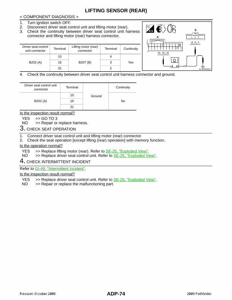
LIFTING SENSOR (REAR)
< COMPONENT DIAGNOSIS >1. Turn ignition switch OFF.2. Disconnect driver seat control unit and lifting motor (rear).3. Check the continuity between driver seat control unit harnessconnector and lifting motor (rear) harness connector.
4. Check the continuity between driver seat control unit harness connector and ground.
Is the inspection result normal?YES >> GO TO 3NO >> Repair or replace harness.
3. CHECK SEAT OPERATION
1. Connect driver seat control unit and lifting motor (rear) connector.2. Check the seat operation [except lifting (rear) operation] with memory function.Is the operation normal?YES >> Replace lifting motor (rear). Refer to SE-25, "Exploded View".NO >> Replace driver seat control unit. Refer to SE-25, "Exploded View".
4. CHECK INTERMITTENT INCIDENT
Refer to GI-49, "Intermittent Incident".Is the inspection result normal?YES >> Replace driver seat control unit. Refer to SE-25, "Exploded View".NO >> Repair or replace the malfunctioning part.
Driver seat control unit connector
TerminalLifting motor (rear)
connectorTerminal Continuity
B202 (A)
10
B207 (B)
4
Yes16 3
31 2
Driver seat control unit connector
Terminal
Ground
Continuity
B202 (A)
10
No16
31
ALJIA0469ZZ
ADP-74

PEDAL ADJUSTING SENSOR
C
D
E
F
G
H
I
K
L
M
A
B
DP
N
O
P
< COMPONENT DIAGNOSIS >
A
PEDAL ADJUSTING SENSOR
Description INFOID:0000000003935561
• The pedal adjusting sensor is installed to the pedal adjusting motor assembly. • The resistance of pedal adjusting sensor is changed according to the forward/backward position of pedal
assembly.• The terminal voltage of automatic drive positioner control unit will be changed according to a change of
pedal adjusting sensor resistance. Automatic drive positioner control unit calculates the pedal assemblyposition from the voltage.
Component Function Check INFOID:0000000003935562
1. CHECK FUNCTION
1. Select “PEDAL SEN” in “Data monitor” mode with CONSULT-III.2. Check the pedal sensor signal under the following condition.
Is the indication normal?YES >> Inspection End.NO >> Perform diagnosis procedure. Refer to ADP-75, "Diagnosis Procedure".
Diagnosis Procedure INFOID:0000000003935563
1. CHECK PEDAL ADJUSTING SENSOR SIGNAL
1. Turn ignition switch ON.2. Check voltage between automatic drive positioner control unit
harness connector and ground.
Is the inspection result normal?YES >> GO TO 4NO >> GO TO 2
2. CHECK PEDAL ADJUSTING SENSOR CIRCUIT
Monitor item Condition Value
PEDAL SEN Pedal positionForward 0.5V
Backward 4.5V
Terminal
ConditionVoltage (V)(Approx.)
(+)
(-)Automatic drive position-er control unit
Terminal
M33 8 GroundPedal as-sembly position
Forward 0.5
Backward 4.5
PIIA4569E
ADP-75

PEDAL ADJUSTING SENSOR
< COMPONENT DIAGNOSIS >1. Turn ignition switch OFF.2. Disconect automatic drive positioner control unit and pedaladjusting motor assembly.3. Check continuity between automatic drive positioner control unit
harnnes connector and pedal adjusting motor assembly harnessconnector.
4. Check continuity between automatic drive positioner control unitharness connector and ground.
Is the inspection result normal?YES >> GO TO 3NO >> Repair or replace harness.
3. CHECK DOOR MIRROR OPERATION
1. Connect automatic drive positioner control unit and pedal adjusting motor assembly.2. Turn ignition switch ON.3. Check door mirror operation with memory function.Is the operation normal?YES >> Replace pedal adjusting motor assembly. Refer to BR-23, "Removal and Installation".NO >> Replace automatic drive positioner control unit. Refer to ADP-159, "Removal and Installation".
4. CHECK INTERMITTENT INCIDENT
Refer to GI-49, "Intermittent Incident".Is the inspection result normal?YES >> Replace automatic drive positioner control unit. Refer to ADP-159, "Removal and Installation".NO >> Repair or replace the malfunctioning part.
Automatic drive posi-tioner
control unit connectorTerminal
Pedal adjusting motor assembly
connectorTerminal Continuity
M33 (A) 8
E110 (B)
4
YesM34 (C)
33 5
41 3
Automatic drive positionercontrol unit connector
Terminal
Ground
Continuity
M33 (A) 8
NoM34 (C)
33
41LIIA2236E
ADP-76

MIRROR SENSOR
C
D
E
F
G
H
I
K
L
M
A
B
DP
N
O
P
< COMPONENT DIAGNOSIS >
A
MIRROR SENSORDRIVER SIDE
DRIVER SIDE : Description INFOID:0000000003935564
• The mirror sensor LH is installed to the door mirror LH.• The resistance of 2 sensors (horizontal and vertical) is changed when the door mirror LH is operated.• Automatic drive positioner control unit calculates the door mirror position according to the change of the volt-
age of 2 sensor input terminals.
DRIVER SIDE : Component Function Check INFOID:0000000003935565
1. CHECK FUNCTION
1. Select “MIR/SEN LH U-D”, “MIR/SEN LH R-L” in “Data monitor” with CONSULT-III.2. Check mirror sensor (driver side) signal under the following condition.
Is the indication normal?YES >> Inspection End.NO >> Perform diagnosis procedure. Refer to ADP-77, "DRIVER SIDE : Diagnosis Procedure".
DRIVER SIDE : Diagnosis Procedure INFOID:0000000003935566
1. CHECK DOOR MIRROR LH SENSOR SIGNAL
1. Turn ignition switch to ACC.2. Check voltage between door mirror LH harness connector and
ground.
Is the inspection result normal?YES >> GO TO 5NO >> GO TO 2
2. CHECK DOOR MIRROR LH SENSOR CIRCUIT 1
Monitor item Condition Value
MIR/SEN LH U-D
Door mirror LH
Close to peak 3.4V
Close to valley 0.6V
MIR/SEN LH R-LClose to right edge 3.4V
Close to left edge 0.6V
Terminals
ConditionVoltage (V)(Approx.)
(+)
(–)Door mirror LH connector
Terminal
D18
10
GroundDoor mirrorLH
Close to peak 3.4
Close to valley 0.6
5Close to right edge 3.4
Close to left edge 0.6
LIIA1766E
ADP-77

MIRROR SENSOR
< COMPONENT DIAGNOSIS >1. Turn ignition switch OFF.2. Disconnect automatic drive positioner control unit and door mir-ror LH.3. Check continuity between automatic drive positioner control unit
harness connector and door mirror LH harness connector.
4. Check continuity between automatic drive positioner control unit harness connector and ground.
Is the inspection result normal?YES >> GO TO 3NO >> Repair or replace harness.
3. CHECK DOOR MIRROR LH SENSOR CIRCUIT 2
1. Check continuity between automatic drive positioner control unitharness connector and door mirror LH harness connector.
2. Check continuity between automatic drive positioner control unitharness connector and ground.
Is the inspection result normal?YES >> GO TO 4NO >> Repair or replace harness.
4. CHECK PEDAL ADJUSTING OPERATION
1. Connect driver seat control unit connector and door mirror LH connector.2. Turn ignition switch ON.3. Check pedal adjusting operation with memory function.Is the operation normal?YES >> Replace door mirror actuator LH. Refer to MIR-15, "Door Mirror Assembly".NO >> Replace automatic drive positioner control unit. Refer to ADP-159, "Removal and Installation".
5. CHECK INTERMITTENT INCIDENT
Refer to GI-49, "Intermittent Incident".Is the inspection result normal?YES >> Replace automatic drive positioner control unit. Refer to ADP-159, "Removal and Installation".NO >> Repair or replace the malfunctioning part.
Automatic drive positioner control
unit connectorTerminal
Door mirror LH connector
Terminal Continuity
M336
D1810
Yes22 5
Automatic drive positioner control unit connector
Terminal
Ground
Continuity
M336
No22
LIIA1768E
Automatic drive positioner control
unit connectorTerminal
Door mirror LH connector
Terminal Continuity
M3433
D184
Yes41 9
Automatic drive positioner control unit connector
Terminal
Ground
Continuity
M3433
No41
LIIA1767E
ADP-78
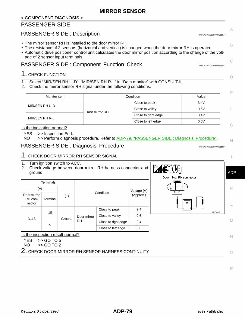
MIRROR SENSOR
C
D
E
F
G
H
I
K
L
M
A
B
DP
N
O
P
< COMPONENT DIAGNOSIS >
A
PASSENGER SIDE
PASSENGER SIDE : Description INFOID:0000000003935567
• The mirror sensor RH is installed to the door mirror RH.• The resistance of 2 sensors (horizontal and vertical) is changed when the door mirror RH is operated.• Automatic drive positioner control unit calculates the door mirror position according to the change of the volt-
age of 2 sensor input terminals.
PASSENGER SIDE : Component Function Check INFOID:0000000003935568
1. CHECK FUNCTION
1. Select “MIR/SEN RH U-D”, “MIR/SEN RH R-L” in “Data monitor” with CONSULT-III.2. Check the mirror sensor RH signal under the following conditions.
Is the indication normal?YES >> Inspection End.NO >> Perform diagnosis procedure. Refer to ADP-79, "PASSENGER SIDE : Diagnosis Procedure".
PASSENGER SIDE : Diagnosis Procedure INFOID:0000000003935569
1. CHECK DOOR MIRROR RH SENSOR SIGNAL
1. Turn ignition switch to ACC.2. Check voltage between door mirror RH harness connector and
ground.
Is the inspection result normal?YES >> GO TO 5NO >> GO TO 2
2. CHECK DOOR MIRROR RH SENSOR HARNESS CONTINUITY
Monitor item Condition Value
MIR/SEN RH U-D
Door mirror RH
Close to peak 3.4V
Close to valley 0.6V
MIR/SEN RH R-LClose to right edge 3.4V
Close to left edge 0.6V
Terminals
ConditionVoltage (V)(Approx.)
(+)
(–)Door mirror RH con-nector
Terminal
D118
10
GroundDoor mirror RH
Close to peak 3.4
Close to valley 0.6
5Close to right edge 3.4
Close to left edge 0.6
LIIA1769E
ADP-79

MIRROR SENSOR
< COMPONENT DIAGNOSIS >1. Turn ignition switch OFF.2. Disconnect automatic drive positioner control unit and door mir-ror RH.3. Check continuity between automatic drive positioner control unit
harness connector and door mirror RH harness connector.
4. Check continuity between automatic drive positioner control unit harness connector and ground.
Is the inspection result normal?YES >> GO TO 3NO >> Repair or replace harness.
3. CHECK DOOR MIRROR RH SENSOR POWER SUPPLY CIRCUIT
1. Check continuity between automatic drive positioner control unitharness connector and door mirror RH harness connector.
2. Check continuity between automatic drive positioner control unitharness connector and ground.
Is the inspection result normal?YES >> GO TO 4NO >> Repair or replace harness.
4. CHECK PEDAL ADJUSTING OPERATION
1. Connect driver seat control unit connector and door mirror RH connector.2. Turn ignition switch ON.3. Check pedal adjusting operation with memory function.Is the operation normal?YES >> Replace door mirror actuator RH. Refer to MIR-15, "Door Mirror Assembly".NO >> Replace automatic drive positioner control unit. Refer to ADP-159, "Removal and Installation".
5. CHECK INTERMITTENT INCIDENT
Refer to GI-49, "Intermittent Incident".Is the inspection result normal?YES >> Replace automatic drive positioner control unit. Refer to ADP-159, "Removal and Installation".NO >> Repair or replace the malfunctioning part.
Automatic drive posi-tioner control unit
connectorTerminal
Door mirror RH connector
Terminal Continuity
M335
D11810
Yes21 5
Automatic drive positioner control unit connector
Terminal
Ground
Continuity
M335
No21
LIIA1772E
Automatic drive posi-tioner control unit
connectorTerminal
Door mirror RH connector
Terminal Continuity
M3433
D1184
Yes41 9
Automatic drive positioner control unit connector
Terminal
Ground
Continuity
M3433
No41
LIIA1771E
ADP-80

SLIDING MOTOR
C
D
E
F
G
H
I
K
L
M
A
B
DP
N
O
P
< COMPONENT DIAGNOSIS >
A
SLIDING MOTOR
Description INFOID:0000000003935570
• The sliding motor LH is installed to the seat frame assembly.• The sliding motor LH is installed with the driver seat control unit.• The seat is slid forward/backward by changing the rotation direction of sliding motor LH.
Component Function Check INFOID:0000000003935571
1. CHECK FUNCTION
1. Select “SEAT SLIDE” in “Active test” mode with CONSULT-III.2. Check the sliding motor LH operation.
Is the operation of relevant parts normal?YES >> Inspection End.NO >> Perform diagnosis procedure. Refer to ADP-81, "Diagnosis Procedure".
Diagnosis Procedure INFOID:0000000003935572
1. CHECK SLIDING MOTOR LH POWER SUPPLY
1. Turn the ignition switch to ACC.2. Perform “Active test” (“SEAT SLIDE”) with CONSULT-lll3. Check voltage between driver seat control unit harness connec-
tor and ground.
Is the inspection result normal?YES >> Replace sliding motor LH. Refer to SE-25, "Exploded View".NO >> GO TO 2
2. CHECK SLIDING MOTOR LH CIRCUIT
Test Item Description
SEAT SLIDE
OFF
Seat sliding
Stop
FR Forward
RR Backward
Terminal
Test ItemVoltage (V)(Approx.)
(+)
(-)Driver seat control unit connector
Terminal
B203
35
GroundSEAT SLIDE
OFF 0
FR (forward) Battery voltage
RR (backward) 0
42
OFF 0
FR (forward) 0
RR (backward) Battery voltage
PIIA4801E
ADP-81

SLIDING MOTOR
< COMPONENT DIAGNOSIS >1. Turn ignition switch OFF.2. Disconnect driver seat control unit and sliding motor LH.3. Check continuity between driver seat control unit harness con-nector and sliding motor LH harness connector.
4. Check continuity between driver seat control unit harness con-nector and ground.
Is the inspection result normal?YES >> GO TO 3NO >> Repair or replace harness.
3. CHECK INTERMITTENT INCIDENT
Refer to GI-49, "Intermittent Incident".Is the inspection result normal?YES >> Replace driver seat control unit. Refer to SE-25, "Exploded View".NO >> Repair or replace the malfunctioning part.
Driver seat control unit connector
TerminalSliding motor LH
connectorTerminal Continuity
B203 (A)35
B204 (B)5
Yes42 1
Driver seat control unit connector
Terminal
Ground
Continuity
B203 (A)35
No42
ALJIA0470ZZ
ADP-82

RECLINING MOTOR
C
D
E
F
G
H
I
K
L
M
A
B
DP
N
O
P
< COMPONENT DIAGNOSIS >
A
RECLINING MOTOR
Description INFOID:0000000003935573
• The reclining motor LH is installed to the seat back frame. • The reclining motor LH is activated with the driver seat control unit. • The seatback is reclined forward/backward by changing the rotation direction of reclining motor LH.
Component Function Check INFOID:0000000003935574
1. CHECK FUNCTION
1. Select “SEAT RECLINING” in “Active test” mode with CONSULT-III.2. Check the reclining motor LH operation.
Is the operation of relevant parts normal?YES >> Inspection End.NO >> Perform diagnosis procedure. Refer to ADP-83, "Diagnosis Procedure".
Diagnosis Procedure INFOID:0000000003935575
1. CHECK RECLINING MOTOR LH POWER SUPPLY
1. Turn the ignition switch to ACC.2. Perform “Active test” (“SEAT RECLINING”) with CONSULT-lll3. Check voltage between driver seat control unit harness connec-
tor and ground.
Is the inspection result normal?YES >> Replace reclining motor LH. Refer to SE-25, "Exploded View".NO >> GO TO 2
2. CHECK RECLINING MOTOR LH CIRCUIT
Test Item Description
SEAT RECLINING
OFF
Seat reclining
Stop
FR Forward
RR Backward
Terminal
Test ItemVoltage (V)(Approx.)
(+)
(-)Driver
seat con-trol unit
connector
Terminal
B203
36
GroundSEAT RE-CLINING
OFF 0
FR (forward) Battery voltage
RR (backward) 0
44
OFF 0
FR (forward) 0
RR (backward) Battery voltage
PIIA4802E
ADP-83

RECLINING MOTOR
< COMPONENT DIAGNOSIS >1. Turn ignition switch OFF.2. Disconnect driver seat control unit and reclining motor LH.3. Check continuity between driver seat control unit harness con-nector and reclining motor harness connector.
4. Check continuity between driver seat control unit harness con-nector and ground.
Is the inspection result normal?YES >> GO TO 3NO >> Repair or replace harness.
3. CHECK INTERMITTENT INCIDENT
Refer to GI-49, "Intermittent Incident".Is the inspection result normal?YES >> Replace driver seat control unit. Refer to SE-25, "Exploded View".NO >> Repair or replace the malfunctioning part.
Driver seat control unit connector
TerminalReclining motor LH
connectorTerminal Continuity
B203 (A)36
B232 (B)2
Yes44 3
Driver seat control unit connector
Terminal
Ground
Continuity
B203 (A)36
No44
ALJIA0471ZZ
ADP-84

LIFTING MOTOR (FRONT)
C
D
E
F
G
H
I
K
L
M
A
B
DP
N
O
P
< COMPONENT DIAGNOSIS >
A
LIFTING MOTOR (FRONT)
Description INFOID:0000000003935576
• The lifting motor (front) is installed to the seat frame assembly. • The lifting motor (front) is activated with the driver seat control unit.• The lifter (front) is moved upward/downward by changing the rotation direction of lifting motor (front).
Component Function Check INFOID:0000000003935577
1. CHECK FUNCTION
1. Select “SEAT LIFTER FR” in “Active test” mode with CONSULT-III.2. Check the lifting motor (front) operation.
Is the operation of relevant parts normal? YES >> Inspection End.NO >> Perform diagnosis procedure. Refer to ADP-85, "Diagnosis Procedure".
Diagnosis Procedure INFOID:0000000003935578
1. CHECK LIFTING MOTOR (FRONT) POWER SUPPLY
1. Turn the ignition switch to ACC.2. Perform “Active test” (“SEAT LIFTER FR”) with CONSULT-lll.3. Check voltage between driver seat control unit harness connec-
tor and ground.
Is the inspection result normal?YES >> Replace lifting motor (front). Refer to SE-25, "Exploded View".NO >> GO TO 2
2. CHECK LIFTING MOTOR (FRONT) CIRCUIT
Test Item Description
SEAT LIFTER FR
OFF
Seat lifting (front)
Stop
UP Upward
DWN Downward
Terminal
Test ItemVoltage (V)(Approx.)
(+)
(-)Driver seat control unit connector
Terminal
B203
37
GroundSEAT LIFTER FR
OFF 0
UP 0
DWN (down) Battery voltage
45
OFF 0
UP Battery voltage
DWN (down) 0
PIIA4805E
ADP-85

LIFTING MOTOR (FRONT)
< COMPONENT DIAGNOSIS >1. Turn ignition switch OFF.2. Disconnect driver seat control unit and lifting motor (front).3. Check continuity between driver seat control unit harness con-nector and lifting motor (front) harness connector.
4. Check continuity between driver seat control unit harness con-nector and ground.
Is the inspection result normal?YES >> GO TO 3NO >> Repair or replace harness.
3. CHECK INTERMITTENT INCIDENT
Refer to GI-49, "Intermittent Incident".Is the inspection result normal?YES >> Replace driver seat control unit. Refer to SE-25, "Exploded View".NO >> Repair or replace the malfunctioning part.
Driver seat control unit connector
TerminalLifting motor (front)
connectorTerminal Continuity
B203 (A)37
B206 (B)1
Yes45 5
Driver seat control unit connector
Terminal
Ground
Continuity
B203 (A)37
No45
ALJIA0472ZZ
ADP-86

LIFTING MOTOR (REAR)
C
D
E
F
G
H
I
K
L
M
A
B
DP
N
O
P
< COMPONENT DIAGNOSIS >
A
LIFTING MOTOR (REAR)
Description INFOID:0000000003935579
• The lifting motor (rear) is installed to the seat frame assembly.• The lifting motor (rear) is activated with the driver seat control unit.• The seat lifter (rear) is moved upward/downward by changing the rotation direction of lifting motor (rear).
Component Function Check INFOID:0000000003935580
1. CHECK FUNCTION
1. Select “SEAT LIFTER RR” in “Active test” mode with CONSULT-III.2. Check the lifting motor (rear) operation.
Is the operation of relevant parts normal?YES >> Inspection End.NO >> Perform diagnosis procedure. Refer to ADP-87, "Diagnosis Procedure".
Diagnosis Procedure INFOID:0000000003935581
1. CHECK LIFTING MOTOR (REAR) POWER SUPPLY
1. Turn the ignition switch OFF.2. Perform “Active test” (“SEAT LIFTER RR”) with CONSULT-lll3. Check voltage between driver seat control unit harness connec-
tor and ground.
Is the inspection result normal?YES >> Replace lifting motor (rear). Refer to SE-25, "Exploded View".NO >> GO TO 2
2. CHECK LIFTING MOTOR (REAR) CIRCUIT
Test Item Description
SEAT LIFTER RR
OFF
Seat lifting (rear)
Stop
UP Upward
DWN Downward
Terminal
Test ItemVoltage (V)(Approx.)
(+)
(-)Driver seat control unit connector
Terminal
B203
38
GroundSEAT LIFTER RR
OFF 0
UP Battery voltage
DWN (down) 0
39
OFF 0
UP 0
DWN (down) Battery voltage
PIIA4804E
ADP-87

LIFTING MOTOR (REAR)
< COMPONENT DIAGNOSIS >1. Disconnect driver seat control unit and lifting motor (rear).2. Check continuity between driver seat control unit harness con-nector and lifting motor (rear) harness connector.
3. Check continuity between driver seat control unit harness con-nector and ground.
Is the inspection result normal?YES >> GO TO 3NO >> Repair or replace harness.
3. CHECK INTERMITTENT INCIDENT
Refer to GI-49, "Intermittent Incident".Is the inspection result normal?YES >> Replace driver seat control unit. Refer to SE-25, "Exploded View".NO >> Repair or replace the malfunctioning part.
Driver seat control unit connector
TerminalLifting motor (rear)
connectorTerminal Continuity
B203 (A)38
B207 (B)5
Yes39 1
Driver seat control unit connector
Terminal
Ground
Continuity
B203 (A)38
No39
ALJIA0473ZZ
ADP-88

PEDAL ADJUSTING MOTOR
C
D
E
F
G
H
I
K
L
M
A
B
DP
N
O
P
< COMPONENT DIAGNOSIS >
A
PEDAL ADJUSTING MOTOR
Description INFOID:0000000003935582
• The pedal adjusting motor is installed to the pedal adjusting motor assembly. • The pedal adjusting motor is activated with the automatic drive positioner control unit.• The pedal assembly is adjusted forward/backward by changing the rotation direction of pedal adjusting
motor.
Component Function Check INFOID:0000000003935583
1. CHECK FUNCTION
1. Select “ADJ PEDAL MOTOR” in “Active test” mode with CONSULT-III.2. Check the pedal adjusting motor operation.
Is the operation of relevant parts normal? YES >> Inspection End.NO >> Perform diagnosis procedure. Refer to ADP-89, "Diagnosis Procedure".
Diagnosis Procedure INFOID:0000000003935584
1. CHECK PEDAL ADJUSTING MOTOR POWER SUPPLY
1. Turn the ignition switch OFF.2. Perform “Active test” (“ADJ PEDAL MOTOR”) with CONSULT-lll.3. Check voltage between automatic drive positioner control unit
harness connector and ground.
Is the inspection result normal?YES >> Replace pedal adjusting motor assembly. Refer to BR-23, "Removal and Installation".NO >> GO TO 2
2. CHECK PEDAL ADJUSTING MOTOR CIRCUIT
Test item Description
ADJ PEDAL MOTOR
OFF
Pedal adjusting motor
Stop
FR Forward
RR Backward
Terminal
Test ItemVoltage
(V)(Approx.)
(+)
(-)
Automatic drive posi-tioner con-
trol unit connector
Terminal
M34
37
GroundADJ PED-AL MOTOR
OFF 0
RR (backward) 0
FR (forward)Battery voltage
45
OFF 0
RR (backward)Battery voltage
FR (forward) 0
PIIA4806E
ADP-89

PEDAL ADJUSTING MOTOR
< COMPONENT DIAGNOSIS >1. Disconnect automatic drive positioner control unit and pedaladjusting motor assembly.2. Check continuity between automatic drive positioner control unit
harness connector and pedal adjusting motor harness connec-tor.
3. Check continuity between automatic drive positioner control unit harness connector and ground.
Is the inspection result normal?YES >> GO TO 3NO >> Repair or replace harness.
3. CHECK INTERMITTENT INCIDENT
Refer to GI-49, "Intermittent Incident".Is the inspection result normal?YES >> Replace automatic drive positioner control unit. Refer to ADP-159, "Removal and Installation".NO >> Repair or replace the malfunctioning part.
Automatic drive positioner control
unit connectorTerminal
Pedal adjusting motor assembly
connectorTerminal Continuity
M34 (A)37
E109 (B)2
Yes45 1
Automatic drive positioner control unit connector
Terminal
Ground
Continuity
M34 (A)37
No45
ALJIA0474ZZ
ADP-90

DOOR MIRROR MOTOR
C
D
E
F
G
H
I
K
L
M
A
B
DP
N
O
P
< COMPONENT DIAGNOSIS >
A
DOOR MIRROR MOTOR
Description INFOID:0000000003935585
It makes mirror face operate from side to side and up and down with the electric power that automatic drivepositioner control unit supplies.
Component Function Check INFOID:0000000003935586
1. CHECK DOOR MIRROR MOTOR FUNCTION
Check the operation with “MIRROR MOTOR RH” and “MIRROR MOTOR LH” in “ACTIVE TEST” mode withCONSULT-IIIRefer to ADP-25, "CONSULT-III Function".Is the inspection result normal?YES >> Door mirror motor function is OK.NO >> Refer to ADP-91, "Diagnosis Procedure".
Diagnosis Procedure INFOID:0000000003935587
1. CHECK DOOR MIRROR MOTOR INPUT SIGNAL
1. Turn ignition switch ON.2. Check voltage between door mirror connector and ground.
Is the inspection result normal?YES >> Refer to ADP-93, "Component Inspection".NO >> GO TO 2
2. CHECK HARNESS CONTINUITY
1. Turn ignition switch OFF.2. Disconnect automatic drive positioner control unit connector and
door mirror.3. Check continuity between automatic drive positioner control unit
connector and door mirror connector.Door mirror LH
TerminalsDoor mirror re-mote control
switch condition
Voltage (V)(Approx.)
(+)
(–)Door mirror connector
Terminal
D18 (LH)D118 (RH)
3
Ground
UP Battery voltage
Other than above 0
2LEFT Battery voltage
Other than above 0
8DOWN / RIGHT Battery voltage
Other than above 0
LIIA1762E
Automatic drive positioner control
unit connectorTerminal
Door mirror LH connector
Terminal Continuity
M33
16
D18
8
Yes31 3
32 2
LIIA1756E
ADP-91

DOOR MIRROR MOTOR
< COMPONENT DIAGNOSIS >Door mirror RH
4. Check continuity between automatic drive positioner control unitconnector and ground.Door mirror LH
Door mirror RH
Is the inspection result normal?YES >> GO TO 3NO >> Repair or replace harness.
3. CHECK AUTOMATIC DRIVE POSITIONER CONTROL UNIT OUTPUT SIGNAL
1. Connect automatic drive positioner control unit.2. Turn ignition switch ON.3. Check voltage between automatic drive positioner control unit
connector and ground.Door mirror LH
Automatic drive posi-tioner control unit con-
nectorTerminal
Door mirror RH connector
Terminal Continuity
M33
14
D118
3
Yes15 2
30 8
Automatic drive position-er control unit connector
Terminal
Ground
Continuity
M33
16
No31
32
Automatic drive position-er control unit connector
Terminal
Ground
Continuity
M33
14
No15
30
LIIA1759E
Terminals
Mirror switch condition
Voltage (V)(Approx.)
(+)
(-)Automatic drive positioner control
unit connectorTerminal
M33
16
Ground
DOWN / RIGHT Battery voltage
Other than above 0
31UP Battery voltage
Other than above 0
32LEFT Battery voltage
Other than above 0
ALJIA0197ZZ
ADP-92

DOOR MIRROR MOTOR
C
D
E
F
G
H
I
K
L
M
A
B
DP
N
O
P
< COMPONENT DIAGNOSIS >
A
Door mirror RH
Is the inspection result normal?YES >> GO TO 4NO >> Replace automatic drive positioner control unit. Refer to ADP-159, "Removal and Installation".
4. CHECK DOOR MIRROR MOTOR
Check door mirror motor.Refer to ADP-93, "Component Inspection".Is the inspection result normal?YES >> Refer to GI-49, "Intermittent Incident".NO >> Replace door mirror actuator. Refer to MIR-15, "Door Mirror Assembly".
Component Inspection INFOID:0000000003935588
1. CHECK DOOR MIRROR MOTOR-I
Check that door mirror motor does not trap foreign objects and does not have any damage.Refer to MIR-15, "Door Mirror Assembly".Is the inspection result normal?YES >> GO TO 2NO >> Replace door mirror actuator. Refer to MIR-15, "Door Mirror Assembly".
2. CHECK DOOR MIRROR MOTOR-II
1. Turn ignition switch OFF.2. Disconnect door mirror.3. Apply 12V to each power supply terminal of door mirror motor.
Is the inspection result normal?YES >> Inspection End.NO >> Replace door mirror actuator. Refer to MIR-15, "Door Mirror Assembly".
Terminals
Mirror switch con-dition
Voltage (V)(Approx.)
(+)
(-)Automatic drive positioner con-
trol unit connec-tor
Terminal
M33
14
Ground
UP Battery voltage
Other than above 0
15LEFT Battery voltage
Other than above 0
30DOWN / RIGHT Battery voltage
Other than above 0
ALJIA0198ZZ
Door mirror connectorTerminal
Operational direction(+) (–)
D18 (LH)D118 (RH)
8 2 RIGHT
2 8 LEFT
3 8 UP
8 3 DOWN
ADP-93
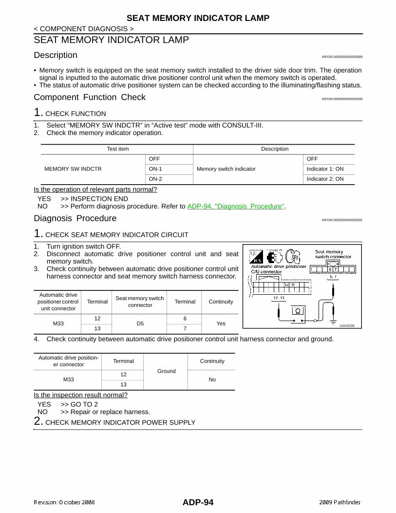
SEAT MEMORY INDICATOR LAMP
< COMPONENT DIAGNOSIS >SEAT MEMORY INDICATOR LAMP
Description INFOID:0000000003935589
• Memory switch is equipped on the seat memory switch installed to the driver side door trim. The operationsignal is inputted to the automatic drive positioner control unit when the memory switch is operated.
• The status of automatic drive positioner system can be checked according to the illuminating/flashing status.
Component Function Check INFOID:0000000003935590
1. CHECK FUNCTION
1. Select “MEMORY SW INDCTR” in “Active test” mode with CONSULT-III. 2. Check the memory indicator operation.
Is the operation of relevant parts normal?YES >> INSPECTION ENDNO >> Perform diagnosis procedure. Refer to ADP-94, "Diagnosis Procedure".
Diagnosis Procedure INFOID:0000000003935591
1. CHECK SEAT MEMORY INDICATOR CIRCUIT
1. Turn ignition switch OFF.2. Disconnect automatic drive positioner control unit and seat
memory switch.3. Check continuity between automatic drive positioner control unit
harness connector and seat memory switch harness connector.
4. Check continuity between automatic drive positioner control unit harness connector and ground.
Is the inspection result normal?YES >> GO TO 2NO >> Repair or replace harness.
2. CHECK MEMORY INDICATOR POWER SUPPLY
Test item Description
MEMORY SW INDCTR
OFF
Memory switch indicator
OFF
ON-1 Indicator 1: ON
ON-2 Indicator 2: ON
Automatic drive positioner control
unit connectorTerminal
Seat memory switch connector
Terminal Continuity
M3312
D56
Yes13 7
Automatic drive position-er connector
Terminal
Ground
Continuity
M3312
No13
LIIA1022E
ADP-94

SEAT MEMORY INDICATOR LAMP
C
D
E
F
G
H
I
K
L
M
A
B
DP
N
O
P
< COMPONENT DIAGNOSIS >
A
Check voltage between seat memory switch harness connector andground.
Is the inspection result normal?YES >> GO TO 3NO >> Check the following.
• Fuse• Harness for open or short between memory indicator and fuse.
3. CHECK MEMORY INDICATOR
Refer to ADP-95, "Component Inspection".Is the inspection result normal?YES >> GO TO 4NO >> Replace seat memory switch. Refer to INT-14, "Removal and Installation".
4. CHECK INTERMITTENT INCIDENT
Refer to GI-49, "Intermittent Incident".Is the inspection result normal?YES >> Replace automatic drive positioner control unit. Refer to ADP-159, "Removal and Installation".NO >> Repair or replace the malfunctioning part.
Component Inspection INFOID:0000000003935592
1. CHECK SEAT MEMORY INDICATOR
1. Disconnect seat memory switch.2. Check continuity between seat memory switch terminals.
Is the inspection result normal?YES >> INSPECTION ENDNO >> Replace seat memory switch. Refer to INT-14, "Removal and Installation".
Seat memory switch connector
Terminals Voltage (V) (Approx.)(+) (–)
D5 5 Ground Battery voltage
PIIA4595E
Terminal
ContinuitySeat memory switch
(+) (-)
65 Yes
7
ALJIA0200ZZ
ADP-95
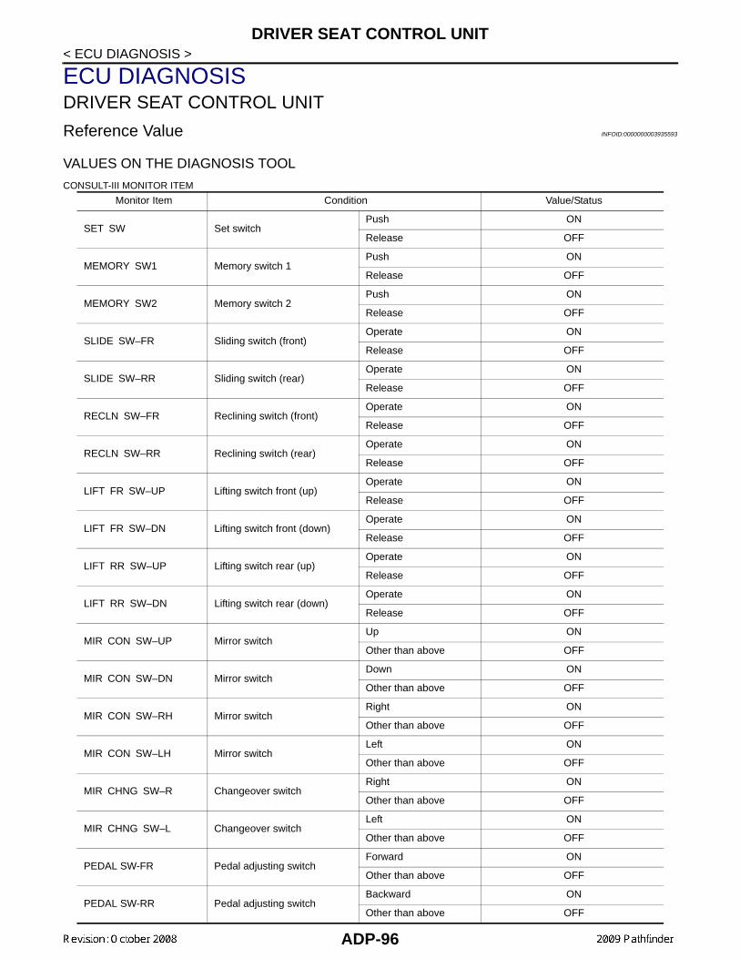
DRIVER SEAT CONTROL UNIT
< ECU DIAGNOSIS >ECU DIAGNOSISDRIVER SEAT CONTROL UNIT
Reference Value INFOID:0000000003935593
VALUES ON THE DIAGNOSIS TOOL
CONSULT-III MONITOR ITEM
Monitor Item Condition Value/Status
SET SW Set switchPush ON
Release OFF
MEMORY SW1 Memory switch 1Push ON
Release OFF
MEMORY SW2 Memory switch 2Push ON
Release OFF
SLIDE SW–FR Sliding switch (front)Operate ON
Release OFF
SLIDE SW–RR Sliding switch (rear)Operate ON
Release OFF
RECLN SW–FR Reclining switch (front)Operate ON
Release OFF
RECLN SW–RR Reclining switch (rear)Operate ON
Release OFF
LIFT FR SW–UP Lifting switch front (up)Operate ON
Release OFF
LIFT FR SW–DN Lifting switch front (down)Operate ON
Release OFF
LIFT RR SW–UP Lifting switch rear (up)Operate ON
Release OFF
LIFT RR SW–DN Lifting switch rear (down)Operate ON
Release OFF
MIR CON SW–UP Mirror switchUp ON
Other than above OFF
MIR CON SW–DN Mirror switchDown ON
Other than above OFF
MIR CON SW–RH Mirror switchRight ON
Other than above OFF
MIR CON SW–LH Mirror switchLeft ON
Other than above OFF
MIR CHNG SW–R Changeover switchRight ON
Other than above OFF
MIR CHNG SW–L Changeover switchLeft ON
Other than above OFF
PEDAL SW-FR Pedal adjusting switchForward ON
Other than above OFF
PEDAL SW-RR Pedal adjusting switchBackward ON
Other than above OFF
ADP-96

DRIVER SEAT CONTROL UNIT
C
D
E
F
G
H
I
K
L
M
A
B
DP
N
O
P
< ECU DIAGNOSIS >
A
TERMINAL LAYOUT
PHYSICAL VALUES
DETENT SW AT selector leverP position OFF
Other than above ON
STARTER SW Ignition positionCranking ON
Other than above OFF
SLIDE PULSE Seat sliding
Forward The numeral value decreases
Backward The numeral value increases
Other than above No change to numeral value
RECLN PULSE Seat reclining
Forward The numeral value decreases
Backward The numeral value increases
Other than above No change to numeral value
LIFT FR PULSE Seat lifter (front)
Up The numeral value decreases
Down The numeral value increases
Other than above No change to numeral value
LIFT RR PULSE Seat lifter (rear)
Up The numeral value decreases
Down The numeral value increases
Other than above No change to numeral value
MIR/SEN RH U–D Door mirror (passenger side)Close to peak 3.4
Close to valley 0.6
MIR/SEN RH R–L Door mirror (passenger side)Close to left edge 3.4
Close to right edge 0.6
MIR/SEN LH U–D Door mirror (driver side)Close to peak 3.4
Close to valley 0.6
MIR/SEN LH R–L Door mirror (driver side)Close to left edge 0.6
Close to right edge 3.4
PEDAL SEN Pedal positionForward 0.5
Backward 4.5
Monitor Item Condition Value/Status
JMJIA0199ZZ
ADP-97
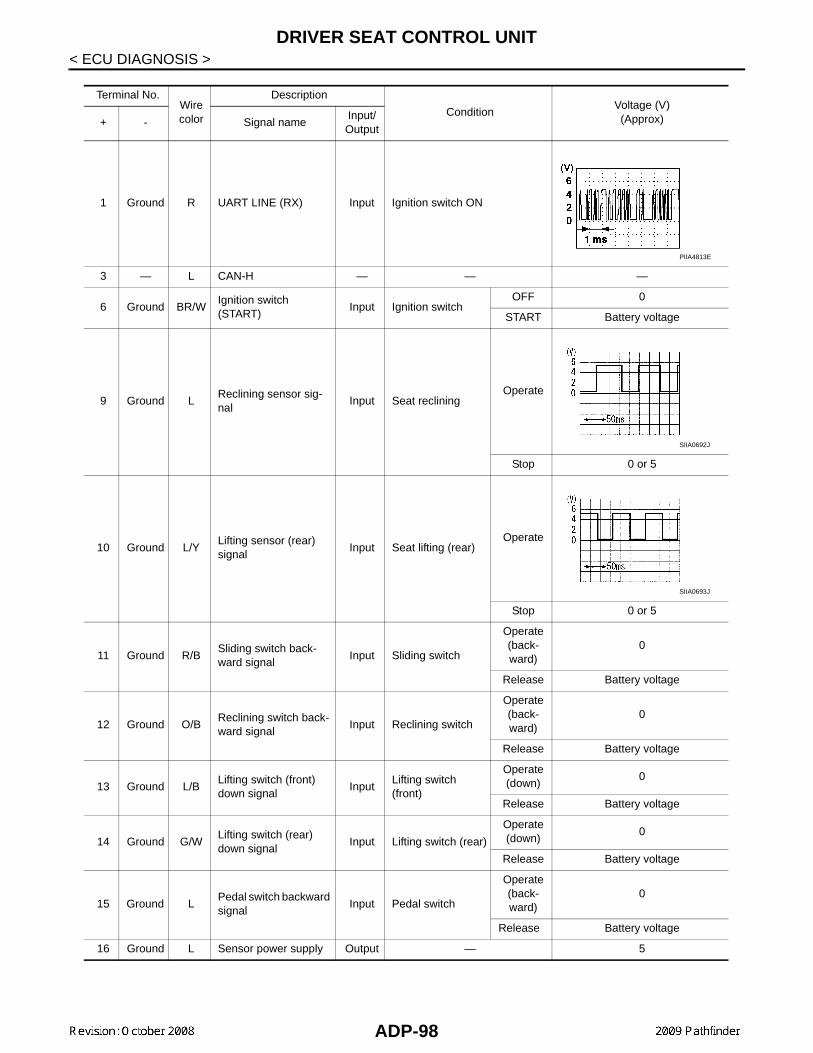
DRIVER SEAT CONTROL UNIT
< ECU DIAGNOSIS >Terminal No.Wire color
Description
ConditionVoltage (V)(Approx)+ - Signal name
Input/Output
1 Ground R UART LINE (RX) Input Ignition switch ON
3 — L CAN-H — — —
6 Ground BR/WIgnition switch (START)
Input Ignition switchOFF 0
START Battery voltage
9 Ground LReclining sensor sig-nal
Input Seat recliningOperate
Stop 0 or 5
10 Ground L/YLifting sensor (rear) signal
Input Seat lifting (rear)Operate
Stop 0 or 5
11 Ground R/BSliding switch back-ward signal
Input Sliding switch
Operate(back-ward)
0
Release Battery voltage
12 Ground O/BReclining switch back-ward signal
Input Reclining switch
Operate(back-ward)
0
Release Battery voltage
13 Ground L/BLifting switch (front) down signal
InputLifting switch (front)
Operate(down)
0
Release Battery voltage
14 Ground G/WLifting switch (rear) down signal
Input Lifting switch (rear)
Operate(down)
0
Release Battery voltage
15 Ground LPedal switch backward signal
Input Pedal switch
Operate (back-ward)
0
Release Battery voltage
16 Ground L Sensor power supply Output — 5
PIIA4813E
SIIA0692J
SIIA0693J
ADP-98

DRIVER SEAT CONTROL UNIT
C
D
E
F
G
H
I
K
L
M
A
B
DP
N
O
P
< ECU DIAGNOSIS >
A
17 Ground R/W UART LINE (TX) Output Ignition switch ON
19 — P CAN-L — — —
21 Ground LA/T device (park posi-tion switch)
Input A/T selector lever
P position 0
Except P position
Battery voltage
24 Ground Y/G Sliding sensor signal Input Seat slidingOperate
Stop 0 or 5
25 Ground R/LLifting sensor (front) signal
Input Seat lifting (front)Operate
Stop 0 or 5
26 Ground P/BSliding switch forward signal
Input Sliding switch
Operate (forward)
0
Release Battery voltage
27 Ground G/BReclining switch for-ward signal
Input Reclining switch
Operate (forward)
0
Release Battery voltage
28 Ground Y/BLifting switch (front) up signal
InputSeat lifting switch (front)
Operate (up)
0
Release Battery voltage
29 Ground R/WLifting switch (rear) up signal
InputSeat lifting switch (rear)
Operate (up)
0
Release Battery voltage
30 Ground L/WPedal switch forward signal
Input Pedal switch
Operate (forward)
0
Release Battery voltage
31 Ground Y Sensor ground — — 0
32 Ground B Ground (signal) — — 0
33 Ground W/LBattery power source (C/B)
Input — Battery voltage
Terminal No.Wire color
Description
ConditionVoltage (V)(Approx)+ - Signal name
Input/Output
PIIA4814E
PIIA3277E
SIIA0691J
ADP-99

DRIVER SEAT CONTROL UNIT
< ECU DIAGNOSIS >35 Ground RSliding motor forward output signal
Output Seat sliding
Operate (forward)
Battery voltage
Release 0
36 Ground R/WReclining motor for-ward output signal
Output Seat reclining
Operate (forward)
Battery voltage
Release 0
37 Ground BLifting motor (front) down output signal
Output Seat lifting (front)
Operate(down)
Battery voltage
Stop 0
38 Ground LLifting motor (rear) up output signal
Output Seat lifting (rear)
Operate(up)
Battery voltage
Stop 0
39 Ground L/WLifting motor (rear) down output signal
Output Seat lifting (rear)
Operate(down)
Battery voltage
Stop 0
40 Ground Y/R Power source (Fuse) Input — Battery voltage
42 Ground GSliding motor back-ward output signal
Output Seat sliding
Operate(back-ward)
Battery voltage
Stop 0
44 Ground G/WReclining motor back-ward output signal
Output Seat reclining
Operate(back-ward)
Battery voltage
Stop 0
45 Ground YLifting motor (front) up output signal
Output Seat lifting (front)
Operate(up)
Battery voltage
Stop 0
48 Ground B Ground (power) — — 0
Terminal No.Wire color
Description
ConditionVoltage (V)(Approx)+ - Signal name
Input/Output
ADP-100

DRIVER SEAT CONTROL UNIT
C
D
E
F
G
H
I
K
L
M
A
B
DP
N
O
P
< ECU DIAGNOSIS >
A
Wiring Diagram INFOID:0000000003935594
ABJWA0006GB
ADP-101

DRIVER SEAT CONTROL UNIT
< ECU DIAGNOSIS >ABJWA0007GB
ADP-102

DRIVER SEAT CONTROL UNIT
C
D
E
F
G
H
I
K
L
M
A
B
DP
N
O
P
< ECU DIAGNOSIS >
A
ABJWA0008GB
ADP-103

DRIVER SEAT CONTROL UNIT
< ECU DIAGNOSIS >ABJWA0009GB
ADP-104

DRIVER SEAT CONTROL UNIT
C
D
E
F
G
H
I
K
L
M
A
B
DP
N
O
P
< ECU DIAGNOSIS >
A
ABJIA0012GB
ADP-105

DRIVER SEAT CONTROL UNIT
< ECU DIAGNOSIS >ABJIA0160GB
ADP-106

DRIVER SEAT CONTROL UNIT
C
D
E
F
G
H
I
K
L
M
A
B
DP
N
O
P
< ECU DIAGNOSIS >
A
ABJIA0013GB
ADP-107
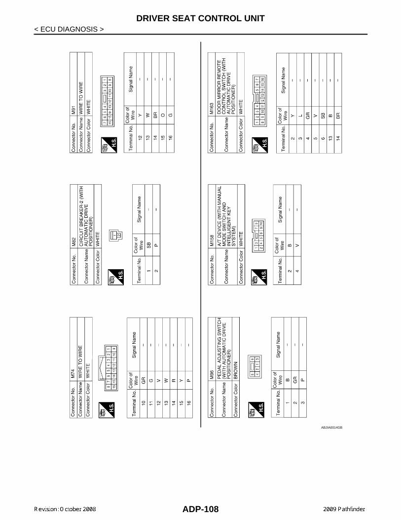
DRIVER SEAT CONTROL UNIT
< ECU DIAGNOSIS >ABJIA0014GB
ADP-108

DRIVER SEAT CONTROL UNIT
C
D
E
F
G
H
I
K
L
M
A
B
DP
N
O
P
< ECU DIAGNOSIS >
A
ABJIA0015GB
ADP-109
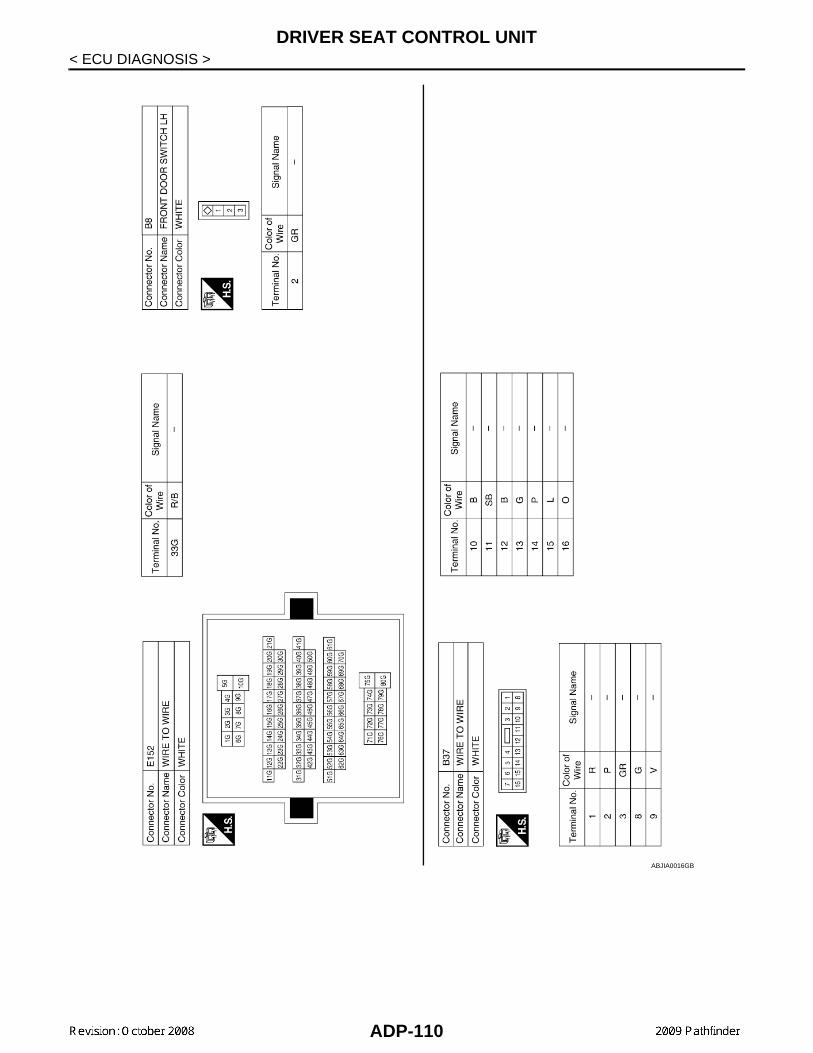
DRIVER SEAT CONTROL UNIT
< ECU DIAGNOSIS >ABJIA0016GB
ADP-110

DRIVER SEAT CONTROL UNIT
C
D
E
F
G
H
I
K
L
M
A
B
DP
N
O
P
< ECU DIAGNOSIS >
A
ABJIA0017GB
ADP-111

DRIVER SEAT CONTROL UNIT
< ECU DIAGNOSIS >ABJIA0018GB
ADP-112

DRIVER SEAT CONTROL UNIT
C
D
E
F
G
H
I
K
L
M
A
B
DP
N
O
P
< ECU DIAGNOSIS >
A
ABJIA0019GB
ADP-113

DRIVER SEAT CONTROL UNIT
< ECU DIAGNOSIS >ABJIA0161GB
ADP-114

DRIVER SEAT CONTROL UNIT
C
D
E
F
G
H
I
K
L
M
A
B
DP
N
O
P
< ECU DIAGNOSIS >
A
Fail Safe INFOID:0000000003935595
The fail-safe mode may be activated if the following symptoms are observed.
FAIL-SAFE MODEWhen any manual and automatic operations are not performed, if any motor operations of front seat LH orpedals are detected for T2 or more, status is judged “Output error”.
ABJIA0162GB
ADP-115

DRIVER SEAT CONTROL UNIT
< ECU DIAGNOSIS >NOTE:The front seat LH position and pedal adjustment functions (see the following table) operate simultaneously inthe order of priority.
*: In conjunction with sliding the seat, the door mirrors are positioned.
CANCEL OF FAIL-SAFE MODEThe mode is cancelled when the A/T selector lever is shifted to P position from any other position.
DTC Index INFOID:0000000003935596
*1:
• 0: Current malfunction is present
• 1-39: Displayed if any previous malfunction is present when current condition is normal. The numeral value increases by one at eachIGN ON to OFF cycle from 1 to 39. The counter remains at 39 even if the number of cycles exceeds it. However, the counter is resetto 1 if any malfunction is detected again, the normal operation is resumed and the ignition switch is turned from OFF to ON.
OPERATED PORTION T2
Seat sliding Approx. 0.1 sec.
Seat reclining Same as above
Seat lifting (Front) Same as above
Seat lifting (Rear) Same as above
Pedal adjust Same as above
Priority Function Priority Function
1 Seat sliding, (door mirror LH/RH)* 4 Seat lifter-FR
2 Pedal 5 Seat lifter-RR
3 Seat reclining
CONSULT-IIIdisplay
Timing*1
Item Reference pageCurrent mal-function
Previous mal-function
CAN COMM CIRCUIT[U1000]
0 1-39 CAN communication ADP-28
SEAT SLIDE[B2112]
0 1-39 Seat slide motor output ADP-29
SEAT RECLINING[B2113]
0 1-39 Seat reclining motor output ADP-30
SEAT LIFTER FRONT[B2114]
0 1-39 Seat lifting motor front output ADP-33
SEAT LIFTER REAR[B2115]
0 1-39 Seat lifting motor rear output ADP-33
ADJ PEDAL MOTOR[B2117]
0 1-39 Pedal adjusting motor output ADP-33
ADJ PEDAL SENSOR[B2120]
0 1-39 Pedal adjusting sensor input ADP-33
DETENT SW[B2126]
0 1-39 Park position switch condition ADP-37
UART COMM[B2128]
0 1-39 UART communication ADP-39
ADP-116
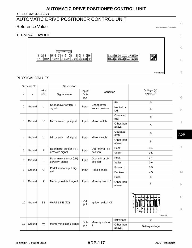
AUTOMATIC DRIVE POSITIONER CONTROL UNIT
C
D
E
F
G
H
I
K
L
M
A
B
DP
N
O
P
< ECU DIAGNOSIS >
A
AUTOMATIC DRIVE POSITIONER CONTROL UNIT
Reference Value INFOID:0000000003935597
TERMINAL LAYOUT
PHYSICAL VALUES
JMJIA0199ZZ
Terminal No.
Wire color
Description
ConditionVoltage (V)(Approx.)+ - Signal name
Input/Out-put
2 Ground LChangeover switch RHsignal
InputChangeover switch position
RH 0
Neutral or LH
5
3 Ground SB Mirror switch up signal Input Mirror switch
Operated(up)
0
Other than above
5
4 Ground V Mirror switch left signal Input Mirror switch
Operated(left)
0
Other than above
5
5 Ground RDoor mirror sensor (RH) up/down signal
InputDoor mirror RH position
Peak 3.4
Valley 0.6
6 Ground LDoor mirror sensor (LH) up/down signal
InputDoor mirror LH position
Peak 3.4
Valley 0.6
8 Ground OPedal sensor input sig-nal
Input Pedal sensorForward 0.5
Backward 4.5
9 Ground LG Memory switch 1 signal Input Memory switch 1
Push 0
Other than above
5
10 Ground SB UART LINE (TX)Out-put
Ignition switch ON
12 Ground W Memory indictor 1 signalOut-put
Memory indictor 1
Illuminate 0
Other than above
Battery voltage
PIIA4813E
ADP-117

AUTOMATIC DRIVE POSITIONER CONTROL UNIT
< ECU DIAGNOSIS >13 Ground Y Memory indictor 2 signalOut-put
Memory indictor 2
Illuminate 0
Other than above
Battery voltage
14 Ground GRDoor mirror motor (RH) up output signal
Out-put
Door mirror RH
Operate(up)
1.5 - Battery voltage
Other than above
0
15 Ground VDoor mirror motor (RH) left output signal
Out-put
Door mirror RH
Operate(left)
1.5 - Battery voltage
Other than above
0
16 Ground O
Door mirror motor (LH) down output signal
Out-put
Door mirror (LH)
Operate(down)
1.5 - Battery voltage
Other than above
0
Door mirror motor (LH) right output signal
Operate(right)
1.5 - Battery voltage
Other than above
0
18 Ground YChangeover switch LHsignal
InputChangeover switch position
LH 0
Neutral or RH
5
19 Ground BRMirror switch down sig-nal
Input Mirror switch
Operate(down)
0
Other than above
5
20 Ground GR Mirror switch right signal Input Mirror switch
Operate(right)
0
Other than above
5
21 Ground PDoor mirror sensor (RH) left/right signal
InputDoor mirror RH position
Left edge 3.4
Right edge 0.6
22 Ground GDoor mirror sensor (LH) left/right signal
InputDoor mirror LH position
Left edge 0.6
Right edge 3.4
24 Ground GR Set switch signal Input Set switch
Push 0
Other than above
5
25 Ground P Memory switch 2 signal Input Memory switch 2
Push 0
Other than above
5
26 Ground G UART LINE (RX) Input Ignition switch ON
Terminal No.
Wire color
Description
ConditionVoltage (V)(Approx.)+ - Signal name
Input/Out-put
PIIA4814E
ADP-118

AUTOMATIC DRIVE POSITIONER CONTROL UNIT
C
D
E
F
G
H
I
K
L
M
A
B
DP
N
O
P
< ECU DIAGNOSIS >
A
30 Ground G
Door mirror motor (RH) down output signal
Out-put
Door mirror (RH)
Operate(down)
1.5 - Battery voltage
Other than above
0
Door mirror motor (RH) right output signal
Operate(right)
1.5 - Battery voltage
Other than above
0
31 Ground RDoor mirror motor (LH)up output signal
Out-put
Door mirror (LH)
Operate(up)
1.5 - Battery voltage
Other than above
0
32 Ground BDoor mirror motor (LH)left output signal
Out-put
Door mirror (LH)
Operate(left)
1.5 - Battery voltage
Other than above
0
33 Ground W Sensor power supply Input — 5
34 Ground R Battery power source Input — Battery voltage
37 Ground GPedal adjusting motor forward output signal
Out-put
Pedal adjusting motor
Operate(forward)
Battery voltage
Other than above
0
39 Ground SB Battery power source — Battery voltage
40 Ground B Ground — — 0
41 Ground Y Sensor ground — — 0
45 Ground BRPedal adjusting motor backward output signal
Out-put
Pedal adjusting motor
Operate(back-ward)
Battery voltage
Other than above
0
48 Ground B Ground — — 0
Terminal No.
Wire color
Description
ConditionVoltage (V)(Approx.)+ - Signal name
Input/Out-put
ADP-119

AUTOMATIC DRIVE POSITIONER CONTROL UNIT
< ECU DIAGNOSIS >Wiring Diagram INFOID:0000000004432031
ABJWA0006GB
ADP-120

AUTOMATIC DRIVE POSITIONER CONTROL UNIT
C
D
E
F
G
H
I
K
L
M
A
B
DP
N
O
P
< ECU DIAGNOSIS >
A
ABJWA0007GB
ADP-121

AUTOMATIC DRIVE POSITIONER CONTROL UNIT
< ECU DIAGNOSIS >ABJWA0008GB
ADP-122

AUTOMATIC DRIVE POSITIONER CONTROL UNIT
C
D
E
F
G
H
I
K
L
M
A
B
DP
N
O
P
< ECU DIAGNOSIS >
A
ABJWA0009GB
ADP-123

AUTOMATIC DRIVE POSITIONER CONTROL UNIT
< ECU DIAGNOSIS >ABJIA0012GB
ADP-124

AUTOMATIC DRIVE POSITIONER CONTROL UNIT
C
D
E
F
G
H
I
K
L
M
A
B
DP
N
O
P
< ECU DIAGNOSIS >
A
ABJIA0160GB
ADP-125

AUTOMATIC DRIVE POSITIONER CONTROL UNIT
< ECU DIAGNOSIS >ABJIA0013GB
ADP-126

AUTOMATIC DRIVE POSITIONER CONTROL UNIT
C
D
E
F
G
H
I
K
L
M
A
B
DP
N
O
P
< ECU DIAGNOSIS >
A
ABJIA0014GB
ADP-127

AUTOMATIC DRIVE POSITIONER CONTROL UNIT
< ECU DIAGNOSIS >ABJIA0015GB
ADP-128
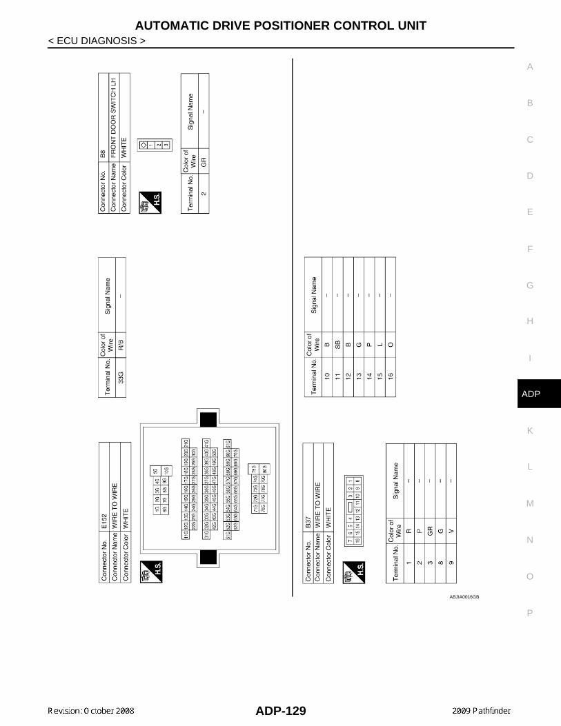
AUTOMATIC DRIVE POSITIONER CONTROL UNIT
C
D
E
F
G
H
I
K
L
M
A
B
DP
N
O
P
< ECU DIAGNOSIS >
A
ABJIA0016GB
ADP-129

AUTOMATIC DRIVE POSITIONER CONTROL UNIT
< ECU DIAGNOSIS >ABJIA0017GB
ADP-130

AUTOMATIC DRIVE POSITIONER CONTROL UNIT
C
D
E
F
G
H
I
K
L
M
A
B
DP
N
O
P
< ECU DIAGNOSIS >
A
ABJIA0018GB
ADP-131

AUTOMATIC DRIVE POSITIONER CONTROL UNIT
< ECU DIAGNOSIS >ABJIA0019GB
ADP-132

AUTOMATIC DRIVE POSITIONER CONTROL UNIT
C
D
E
F
G
H
I
K
L
M
A
B
DP
N
O
P
< ECU DIAGNOSIS >
A
ABJIA0161GB
ADP-133

AUTOMATIC DRIVE POSITIONER CONTROL UNIT
< ECU DIAGNOSIS >ABJIA0162GB
ADP-134

BCM (BODY CONTROL MODULE)
C
D
E
F
G
H
I
K
L
M
A
B
DP
N
O
P
< ECU DIAGNOSIS >
A
BCM (BODY CONTROL MODULE)
Reference Value INFOID:0000000004432032
VALUES ON THE DIAGNOSIS TOOL
Monitor Item Condition Value/Status
AIR COND SWA/C switch OFF OFF
A/C switch ON ON
AUT LIGHT SYSOutside of the room is dark OFF
Outside of the room is bright ON
AUTO LIGHT SWLighting switch OFF OFF
Lighting switch AUTO ON
BACK DOOR SWBack door closed OFF
Back door opened ON
CDL LOCK SWDoor lock/unlock switch does not operate OFF
Press door lock/unlock switch to the LOCK side ON
CDL UNLOCK SWDoor lock/unlock switch does not operate OFF
Press door lock/unlock switch to the UNLOCK side ON
DOOR SW-ASFront door RH closed OFF
Front door RH opened ON
DOOR SW-DRFront door LH closed OFF
Front door LH opened ON
DOOR SW-RLRear door LH closed OFF
Rear door LH opened ON
DOOR SW-RRRear door RH closed OFF
Rear door RH opened ON
ENGINE RUNEngine stopped OFF
Engine running ON
FR FOG SWFront fog lamp switch OFF OFF
Front fog lamp switch ON ON
FR WASHER SWFront washer switch OFF OFF
Front washer switch ON ON
FR WIPER LOWFront wiper switch OFF OFF
Front wiper switch LO ON
FR WIPER HIFront wiper switch OFF OFF
Front wiper switch HI ON
FR WIPER INTFront wiper switch OFF OFF
Front wiper switch INT ON
FR WIPER STOPAny position other than front wiper stop position OFF
Front wiper stop position ON
HAZARD SWWhen hazard switch is not pressed OFF
When hazard switch is pressed ON
LIGHT SW 1STLighting switch OFF OFF
Lighting switch 1st ON
ADP-135

BCM (BODY CONTROL MODULE)
< ECU DIAGNOSIS >HEADLAMP SW1Headlamp switch OFF OFF
Headlamp switch 1st ON
HEADLAMP SW2Headlamp switch OFF OFF
Headlamp switch 1st ON
HI BEAM SWHigh beam switch OFF OFF
High beam switch HI ON
H/L WASH SWNOTE:The item is indicated, but not monitored
OFF
IGN ON SWIgnition switch OFF or ACC OFF
Ignition switch ON ON
IGN SW CANIgnition switch OFF or ACC OFF
Ignition switch ON ON
INT VOLUME Wiper intermittent dial is in a dial position 1 - 7 1 - 7
I-KEY LOCK1LOCK button of Intelligent Key is not pressed OFF
LOCK button of Intelligent Key is pressed ON
I-KEY UNLOCK1UNLOCK button of Intelligent Key is not pressed OFF
UNLOCK button of Intelligent Key is pressed ON
KEY ON SWMechanical key is removed from key cylinder OFF
Mechanical key is inserted to key cylinder ON
KEYLESS LOCK2LOCK button of key fob is not pressed OFF
LOCK button of key fob is pressed ON
KEYLESS UNLOCK2UNLOCK button of key fob is not pressed OFF
UNLOCK button of key fob is pressed ON
OIL PRESS SW
• Ignition switch OFF or ACC• Engine running
OFF
Ignition switch ON ON
PASSING SWOther than lighting switch PASS OFF
Lighting switch PASS ON
PUSH SW1Return to ignition switch to LOCK position OFF
Press ignition switch ON
REAR DEF SWRear window defogger switch OFF OFF
Rear window defogger switch ON ON
RKE LOCK AND
UNLOCK2NOTE:The item is indicated, but not monitored
OFF
ON
RR WASHER SWRear washer switch OFF OFF
Rear washer switch ON ON
RR WIPER INTRear wiper switch OFF OFF
Rear wiper switch INT ON
RR WIPER ON Rear wiper switch OFF OFF
Rear wiper switch ON ON
RR WIPER STOPRear wiper stop position OFF
Other than rear wiper stop position ON
TAIL LAMP SWLighting switch OFF OFF
Lighting switch 1ST ON
Monitor Item Condition Value/Status
ADP-136

BCM (BODY CONTROL MODULE)
C
D
E
F
G
H
I
K
L
M
A
B
DP
N
O
P
< ECU DIAGNOSIS >
A
1: With Intelligent Key
2: With remote keyless entry system
TRNK OPNR SWWhen back door opener switch is not pressed OFF
When back door opener switch is pressed ON
TURN SIGNAL LTurn signal switch OFF OFF
Turn signal switch LH ON
TURN SIGNAL RTurn signal switch OFF OFF
Turn signal switch RH ON
VEHICLE SPEED While driving Equivalent to speedometer reading
Monitor Item Condition Value/Status
ADP-137

BCM (BODY CONTROL MODULE)
< ECU DIAGNOSIS >Terminal Layout INFOID:0000000004432033
Physical Values INFOID:0000000004432034
LIIA2443E
ADP-138

BCM (BODY CONTROL MODULE)
C
D
E
F
G
H
I
K
L
M
A
B
DP
N
O
P
< ECU DIAGNOSIS >
A
TerminalWire color
Signal nameSignal input/output
Measuring conditionReference value or waveform
(Approx.)Ignition switch
Operation or condition
1 BRIgnition keyhole illumi-nation
Output OFFDoor is locked (SW OFF) Battery voltage
Door is unlocked (SW ON) 0V
2 PCombination switch input 5
Input ONLighting, turn, wiper OFFWiper dial position 4
3 SBCombination switch input 4
Input ONLighting, turn, wiper OFFWiper dial position 4
4 VCombination switch input 3
Input ONLighting, turn, wiper OFFWiper dial position 4
5 LCombination switch input 2
Input ONLighting, turn, wiper OFFWiper dial position 4
6 RCombination switch input 1
9 YRear window defogger switch
Input ON
Rear window defogger switch ON
0V
Rear window defogger switch OFF
5V
11 G/BIgnition switch (ACC or ON)
InputACC or
ONIgnition switch ACC or ON Battery voltage
12 LG Front door switch RH Input OFFON (open) 0V
OFF (closed) Battery voltage
13 L Rear door switch RH Input OFFON (open) 0V
OFF (closed) Battery voltage
15 WTire pressure warning check connector
Input OFF — 5V
18 BRRemote keyless entry receiver and optical sensor (ground)
Output OFF — 0V
SKIA5291E
SKIA5292E
SKIA5291E
SKIA5292E
ADP-139

BCM (BODY CONTROL MODULE)
< ECU DIAGNOSIS >19 VRemote keyless entry receiver (power sup-ply)
Output OFF Ignition switch OFF
20 GRemote keyless entry receiver (signal)
Input OFF
Stand-by (keyfob buttons re-leased)
When remote keyless entry receiver receives signal from keyfob (keyfob buttons pressed)
21 GR NATS antenna amp. InputOFF →
ONIgnition switch (OFF → ON)
Just after turning ignition switch ON: Pointer of tester should
move for approx. 1 second, then return to battery voltage.
22 V BUS — —Ignition switch ON or power window timer operates
23 GSecurity indicator lamp
Output OFFGoes OFF → illuminates (Ev-ery 2.4 seconds)
Battery voltage → 0V
25 BR NATS antenna amp. InputOFF →
ONIgnition switch (OFF → ON)
Just after turning ignition switch ON: Pointer of tester should
move for approx. 1 second, then return to battery voltage.
27 WCompressor ON sig-nal
Input ONA/C switch OFF 5V
A/C switch ON 0V
28 LG Front blower monitor Input ONFront blower motor OFF Battery voltage
Front blower motor ON 0V
29 G Hazard switch Input OFFON 0V
OFF 5V
301 GBack door opener switch
Input OFFON (open) 0V
OFF (closed) Battery voltage
302 SBBack door opener switch
Input OFFON (open) 0V
OFF (closed) Battery voltage
TerminalWire color
Signal nameSignal input/output
Measuring conditionReference value or waveform
(Approx.)Ignition switch
Operation or condition
LIIA1893E
LIIA1894E
LIIA1895E
PIIA2344E
ADP-140

BCM (BODY CONTROL MODULE)
C
D
E
F
G
H
I
K
L
M
A
B
DP
N
O
P
< ECU DIAGNOSIS >
A
32 OCombination switch output 5
Output ONLighting, turn, wiper OFFWiper dial position 4
33 GRCombination switch output 4
Output ONLighting, turn, wiper OFFWiper dial position 4
34 GCombination switch output 3
Output ONLighting, turn, wiper OFFWiper dial position 4
35 BRCombination switch output 2
Output ONLighting, turn, wiper OFFWiper dial position 4
36 LGCombination switch output 1
371 BKey switch and key lock solenoid
Input OFFKey inserted Battery voltage
Key inserted 0V
372 BKey switch and igni-tion knob switch
Input OFFIntelligent Key inserted Battery voltage
Intelligent Key inserted 0V
38 W/R Ignition switch (ON) Input ON — Battery voltage
39 L CAN-H — — — —
40 P CAN-L — — — —
42 LGGlass hatch ajar switch
Input ONGlass hatch open 0
Glass hatch closed Battery
43 P Back door latch switch Input OFFON (open) 0V
OFF (closed) Battery voltage
TerminalWire color
Signal nameSignal input/output
Measuring conditionReference value or waveform
(Approx.)Ignition switch
Operation or condition
SKIA5291E
SKIA5292E
SKIA5291E
SKIA5292E
ADP-141

BCM (BODY CONTROL MODULE)
< ECU DIAGNOSIS >44 ORear wiper auto stop switch
Input ON
Rise up position (rear wiper arm on stopper)
0V
A Position (full clockwise stop position)
Battery voltage
Forward sweep (counterclock-wise direction)
Fluctuating
B Position (full counterclock-wise stop position)
0V
Reverse sweep (clockwise di-rection)
Fluctuating
47 GR Front door switch LH Input OFFON (open) 0V
OFF (closed) Battery voltage
48 P Rear door switch LH Input OFFON (open) 0V
OFF (closed) Battery voltage
49 L Cargo lamp Output OFFAny door open (ON) 0V
All doors closed (OFF) Battery voltage
51 GTrailer turn signal (right)
Output ON Turn right ON
52 V Trailer turn signal (left) Output ON Turn left ON
53 LBack door latch actua-tor
Output OFFOFF 0
ON Battery voltage
55 WRear wiper output cir-cuit 1
Output ONOFF 0
ON Battery voltage
56 V Battery saver output OutputOFF
30 minutes after ignition switch is turned OFF
0V
ON — Battery voltage
57 R/Y Battery power supply Input OFF — Battery voltage
58 W Optical sensor Input ON
When optical sensor is illumi-nated
3.1V or more
When optical sensor is not illu-minated
0.6V or less
59 GRFront door lock as-sembly LH actuator (unlock)
Output OFFOFF (neutral) 0V
ON (unlock) Battery voltage
TerminalWire color
Signal nameSignal input/output
Measuring conditionReference value or waveform
(Approx.)Ignition switch
Operation or condition
SKIA3009J
SKIA3009J
ADP-142

BCM (BODY CONTROL MODULE)
C
D
E
F
G
H
I
K
L
M
A
B
DP
N
O
P
< ECU DIAGNOSIS >
A
1: With remote keyless entry system
2: With Intelligent Key system
60 LG Turn signal (left) Output ON Turn left ON
61 G Turn signal (right) Output ON Turn right ON
63 BRInterior room/map lamp
Output OFFAny door switch
ON (open) 0V
OFF (closed) Battery voltage
65 VAll door lock actuators (lock)
Output OFFOFF (neutral) 0V
ON (lock) Battery voltage
66 L
Front door lock actua-tor RH, rear door lock actuators LH/RH and glass hatch lock actu-ator (unlock)
Output OFF
OFF (neutral) 0V
ON (unlock) Battery voltage
67 B Ground Input ON — 0V
68 OPower window power supply (RAP)
Output —
Ignition switch ON Battery voltage
Within 45 seconds after igni-tion switch OFF
Battery voltage
More than 45 seconds after ig-nition switch OFF
0V
When front door LH or RH is open or power window timer operates
0V
69 LPower window power supply
Output — — Battery voltage
70 W Battery power supply Input OFF — Battery voltage
TerminalWire color
Signal nameSignal input/output
Measuring conditionReference value or waveform
(Approx.)Ignition switch
Operation or condition
SKIA3009J
SKIA3009J
ADP-143

BCM (BODY CONTROL MODULE)
< ECU DIAGNOSIS >Wiring Diagram INFOID:0000000004432035
ABMWA0070GB
ADP-144
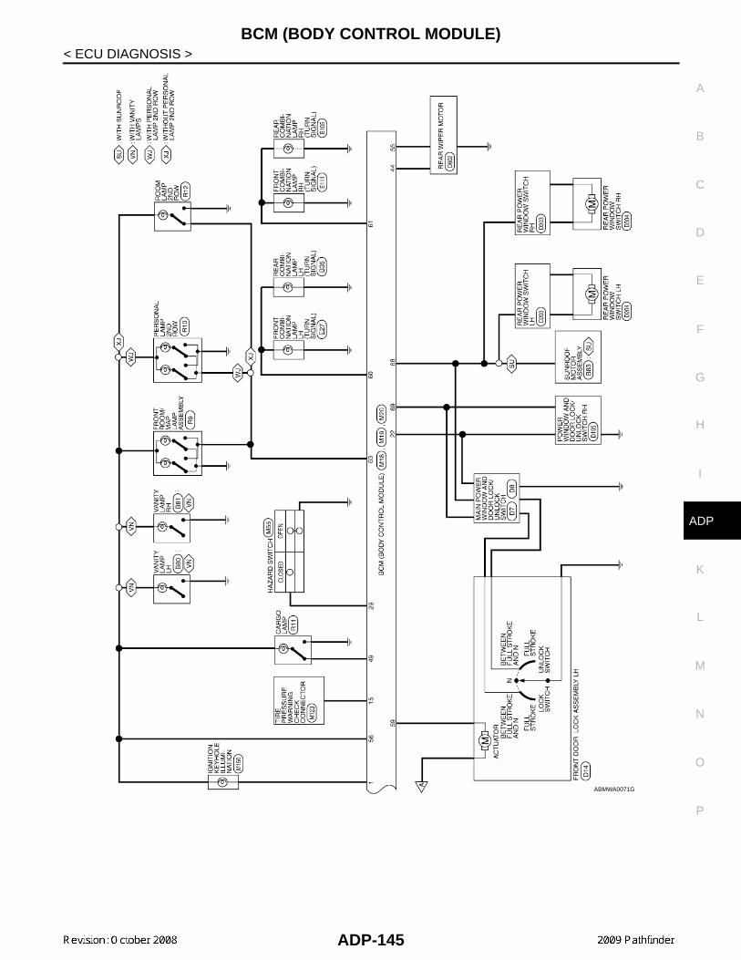
BCM (BODY CONTROL MODULE)
C
D
E
F
G
H
I
K
L
M
A
B
DP
N
O
P
< ECU DIAGNOSIS >
A
ABMWA0071GB
ADP-145

BCM (BODY CONTROL MODULE)
< ECU DIAGNOSIS >ABMIA0161GB
ADP-146

BCM (BODY CONTROL MODULE)
C
D
E
F
G
H
I
K
L
M
A
B
DP
N
O
P
< ECU DIAGNOSIS >
A
Fail Safe INFOID:0000000004432036
Fail-safe indexBCM performs fail-safe control when any DTC listed below is detected.
ABMIA0162GB
ADP-147

BCM (BODY CONTROL MODULE)
< ECU DIAGNOSIS >DTC Inspection Priority Chart INFOID:0000000004432037
If some DTCs are displayed at the same time, perform inspections one by one based on the following prioritychart.
DTC Index INFOID:0000000004432038
NOTE:Details of time display
• CRNT: Displays when there is a malfunction now or after returning to the normal condition until turning igni-tion switch OFF → ON again.
• 1 - 39: Displayed if any previous malfunction is present when current condition is normal. It increases like 1→ 2 → 3...38 → 39 after returning to the normal condition whenever ignition switch OFF → ON. The counterremains at 39 even if the number of cycles exceeds it. It is counted from 1 again when turning ignition switchOFF → ON after returning to the normal condition if the malfunction is detected again.
Display contents of CONSULT Fail-safe Cancellation
U1000: CAN COMM CIRCUIT Inhibit engine crankingWhen the BCM re-establishes communication with the other mod-ules.
U1010: CONTROL UNIT (CAN) Inhibit engine cranking When the BCM re-start communicating with the other modules.
Priority DTC
1• U1000: CAN COMM CIRCUIT• U1010: CONTROL UNIT (CAN)
2
• B2190: NATS ANTENNA AMP• B2191: DIFFERENCE OF KEY• B2192: ID DISCORD BCM-ECM• B2193: CHAIN OF BCM-ECM• B2013: STRG COMM 1• B2552: INTELLIGENT KEY• B2590: NATS MALFUNCTION
3• C1729: VHCL SPEED SIG ERR• C1735: IGNITION SIGNAL
4
• C1704: LOW PRESSURE FL• C1705: LOW PRESSURE FR• C1706: LOW PRESSURE RR• C1707: LOW PRESSURE RL• C1708: [NO DATA] FL• C1709: [NO DATA] FR• C1710: [NO DATA] RR• C1711: [NO DATA] RL• C1712: [CHECKSUM ERR] FL• C1713: [CHECKSUM ERR] FR• C1714: [CHECKSUM ERR] RR• C1715: [CHECKSUM ERR] RL• C1716: [PRESSDATA ERR] FL• C1717: [PRESSDATA ERR] FR• C1718: [PRESSDATA ERR] RR• C1719: [PRESSDATA ERR] RL• C1720: [CODE ERR] FL• C1721: [CODE ERR] FR• C1722: [CODE ERR] RR• C1723: [CODE ERR] RL• C1724: [BATT VOLT LOW] FL• C1725: [BATT VOLT LOW] FR• C1726: [BATT VOLT LOW] RR• C1727: [BATT VOLT LOW] RL
ADP-148
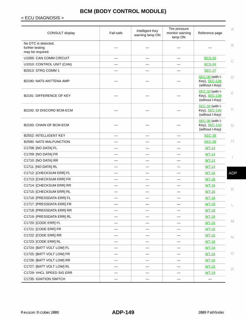
BCM (BODY CONTROL MODULE)
C
D
E
F
G
H
I
K
L
M
A
B
DP
N
O
P
< ECU DIAGNOSIS >
A
CONSULT display Fail-safeIntelligent Key
warning lamp ON
Tire pressure monitor warning
lamp ONReference page
No DTC is detected.further testingmay be required.
— — — —
U1000: CAN COMM CIRCUIT — — — BCS-33
U1010: CONTROL UNIT (CAN) — — — BCS-34
B2013: STRG COMM 1 — — — SEC-27
B2190: NATS ANTTENA AMP — — —SEC-30 (with I-Key), SEC-136 (without I-Key)
B2191: DIFFERENCE OF KEY — — —SEC-33 (with I-Key), SEC-139 (without I-Key)
B2192: ID DISCORD BCM-ECM — — —SEC-34 (with I-Key), SEC-140 (without I-Key)
B2193: CHAIN OF BCM-ECM — — —SEC-36 (with I-Key), SEC-142 (without I-Key)
B2552: INTELLIGENT KEY — — — SEC-38
B2590: NATS MALFUNCTION — — — SEC-39
C1708: [NO DATA] FL — — — WT-14
C1709: [NO DATA] FR — — — WT-14
C1710: [NO DATA] RR — — — WT-14
C1711: [NO DATA] RL — — — WT-14
C1712: [CHECKSUM ERR] FL — — — WT-16
C1713: [CHECKSUM ERR] FR — — — WT-16
C1714: [CHECKSUM ERR] RR — — — WT-16
C1715: [CHECKSUM ERR] RL — — — WT-16
C1716: [PRESSDATA ERR] FL — — — WT-18
C1717: [PRESSDATA ERR] FR — — — WT-18
C1718: [PRESSDATA ERR] RR — — — WT-18
C1719: [PRESSDATA ERR] RL — — — WT-18
C1720: [CODE ERR] FL — — — WT-16
C1721: [CODE ERR] FR — — — WT-16
C1722: [CODE ERR] RR — — — WT-16
C1723: [CODE ERR] RL — — — WT-16
C1724: [BATT VOLT LOW] FL — — — WT-16
C1725: [BATT VOLT LOW] FR — — — WT-16
C1726: [BATT VOLT LOW] RR — — — WT-16
C1727: [BATT VOLT LOW] RL — — — WT-16
C1729: VHCL SPEED SIG ERR — — — WT-19
C1735: IGNITION SWITCH — — — —
ADP-149

ADP SYSTEM SYMPTOMS
< SYMPTOM DIAGNOSIS >SYMPTOM DIAGNOSISADP SYSTEM SYMPTOMS
Symptom Table INFOID:0000000003935603
NOTE: Always perform the “Basic Inspection” before performing diagnosis in the following table. Refer to ADP-5,"Work Flow".
SYMPTOM 1
SYMPTOM 2
SYMPTOM 3
SYMPTOM 4
Symptom Diagnosis procedureReference
page
Manual functions (for specific part) do not operate
Sliding operation Check sliding switch. ADP-44
Reclining operation Check reclining switch. ADP-46
Lifting operation (front) Check lifting switch (front). ADP-48
Lifting operation (rear) Check lifting switch (rear). ADP-50
Pedal operation1. Check pedal adjusting switch. ADP-52
2. Check pedal adjusting sensor. ADP-75
Door mirror operation1. Changeover switch. ADP-57
2. Mirror switch ADP-59
All parts of seatCheck power seat switch ground cir-cuit.
ADP-62
Symptom Diagnosis procedureReference
page
Memory functions (for specific part) do not operate
Sliding operation Check sliding sensor. ADP-67
Reclining operation Check reclining sensor. ADP-69
Lifting operation (front) Check lifting sensor (front). ADP-71
Lifting operation (rear) Check lifting sensor (rear). ADP-73
Pedal operation Check pedal adjusting sensor. ADP-75
Door mirror operation Check door mirror sensor.
Driver side: ADP-77
Passenger side:
ADP-79
Symptom Diagnosis procedureReference
page
Memory functions and manual func-tions (for specific part) do not operate
Sliding operation Check sliding motor. ADP-81
Reclining operation Check reclining motor. ADP-83
Lifting operation (front) Check lifting motor (front). ADP-85
Lifting operation (rear) Check lifting motor (rear). ADP-87
Pedal operation Check pedal adjusting motor. ADP-89
Door mirror operation Check door mirror motor. ADP-91
ADP-150

ADP SYSTEM SYMPTOMS
C
D
E
F
G
H
I
K
L
M
A
B
DP
N
O
P
< SYMPTOM DIAGNOSIS >
A
SYMPTOM 5
SYMPTOM 6
Symptom Diagnosis procedureReference
page
Entry/Exit assist function does not operate.
1. Check system setting. ADP-20
2. Perform initialization. ADP-21
3. Check front door switch (driver side). ADP-65
Intelligent Key interlock function does not operate.(Other automatic operations and Intelligent Key system are normal)
1. Check door lock function. DLK-22
2. Perform memory storing. ADP-10
Symptom Diagnosis procedureReference
page
Memory indicators 1 and/or 2 do not illuminate. 1. Check seat memory switch. ADP-55
2. Check seat memory indicator. ADP-94
Symptom Diagnosis procedureReference
page
Memory operation does not operate. Check A/T device (park position switch). ADP-63
ADP-151

NORMAL OPERATING CONDITION
< SYMPTOM DIAGNOSIS >NORMAL OPERATING CONDITION
Description INFOID:0000000003935604
The following symptoms are normal operations, and they do not indicate a malfunction.
Symptom Cause Action to take Reference page
Entry/Exit assist function does not operate.
No initialization has been performed. Perform initialization. ADP-19
Entry/exit assist function is disabled.NOTE:The entry/exit assist function is disabled before delivery (initial setting).
Change the settings. ADP-22
Entry assist function does not op-erate.
Manual operation with power seat switch was performed after exit assist function excution.
Perform the memory function.
ADP-22
Memory function, entry/exit as-sist function or Intelligent Key in-terlock function does not operate.
The operating conditions are not fulfilled.Fulfill the operation
conditions.
Memory function: ADP-16
Exit assist function: ADP-20
Entry assist function: ADP-22
Intelligent Key interlock function: ADP-10
ADP-152
PRECAUTIONS
C
D
E
F
G
H
I
K
L
M
A
B
DP
N
O
P
< PRECAUTION >
A
PRECAUTIONPRECAUTIONS
Precaution for Supplemental Restraint System (SRS) "AIR BAG" and "SEAT BELT PRE-TENSIONER" INFOID:0000000003935605
The Supplemental Restraint System such as “AIR BAG” and “SEAT BELT PRE-TENSIONER”, used alongwith a front seat belt, helps to reduce the risk or severity of injury to the driver and front passenger for certaintypes of collision. This system includes seat belt switch inputs and dual stage front air bag modules. The SRSsystem uses the seat belt switches to determine the front air bag deployment, and may only deploy one frontair bag, depending on the severity of a collision and whether the front occupants are belted or unbelted.Information necessary to service the system safely is included in the SR and SB section of this Service Man-ual.WARNING:• To avoid rendering the SRS inoperative, which could increase the risk of personal injury or death in
the event of a collision which would result in air bag inflation, all maintenance must be performed byan authorized NISSAN/INFINITI dealer.
• Improper maintenance, including incorrect removal and installation of the SRS, can lead to personalinjury caused by unintentional activation of the system. For removal of Spiral Cable and Air BagModule, see the SR section.
• Do not use electrical test equipment on any circuit related to the SRS unless instructed to in thisService Manual. SRS wiring harnesses can be identified by yellow and/or orange harnesses or har-ness connectors.
Precaution Necessary for Steering Wheel Rotation After Battery DisconnectINFOID:0000000004448898
NOTE:• This Procedure is applied only to models with Intelligent Key system and NATS (NISSAN ANTI-THEFT SYS-
TEM).• Remove and install all control units after disconnecting both battery cables with the ignition knob in the
″LOCK″ position.• Always use CONSULT-III to perform self-diagnosis as a part of each function inspection after finishing work.
If DTC is detected, perform trouble diagnosis according to self-diagnostic results.For models equipped with the Intelligent Key system and NATS, an electrically controlled steering lock mech-anism is adopted on the key cylinder.For this reason, if the battery is disconnected or if the battery is discharged, the steering wheel will lock andsteering wheel rotation will become impossible.If steering wheel rotation is required when battery power is interrupted, follow the procedure below beforestarting the repair operation.
OPERATION PROCEDURE1. Connect both battery cables.
NOTE:Supply power using jumper cables if battery is discharged.
2. Use the Intelligent Key or mechanical key to turn the ignition switch to the ″ACC″ position. At this time, thesteering lock will be released.
3. Disconnect both battery cables. The steering lock will remain released and the steering wheel can berotated.
4. Perform the necessary repair operation.5. When the repair work is completed, return the ignition switch to the ″LOCK″ position before connecting
the battery cables. (At this time, the steering lock mechanism will engage.)6. Perform a self-diagnosis check of all control units using CONSULT-III.
Precaution for Work INFOID:0000000003935606
• When removing or disassembling each component, be careful not to damage or deform it. If a componentmay be subject to interference, be sure to protect it with a shop cloth.
ADP-153
PRECAUTIONS
< PRECAUTION >• When removing (disengaging) components with a screwdriver or similar tool, be sure to wrap the componentwith a shop cloth or vinyl tape to protect it.• Protect the removed parts with a shop cloth and keep them.• Replace a deformed or damaged clip.• If a part is specified as a non-reusable part, always replace it with new one.• Be sure to tighten bolts and nuts securely to the specified torque.• After re-installation is completed, be sure to check that each part works normally.• Follow the steps below to clean components.- Water soluble foul: Dip a soft cloth into lukewarm water, and wring the water out of the cloth to wipe the
fouled area.Then rub with a soft and dry cloth.
- Oily foul: Dip a soft cloth into lukewarm water with mild detergent (concentration: within 2 to 3%), and wipethe fouled area.Then dip a cloth into fresh water, and wring the water out of the cloth to wipe the detergent off. Then rub witha soft and dry cloth.
• Do not use organic solvent such as thinner, benzene, alcohol, or gasoline.• For genuine leather seats, use a genuine leather seat cleaner.
ADP-154

PRE-INSPECTION FOR DIAGNOSTIC
C
D
E
F
G
H
I
K
L
M
A
B
DP
N
O
P
< ON-VEHICLE MAINTENANCE >
A
ON-VEHICLE MAINTENANCEPRE-INSPECTION FOR DIAGNOSTIC
Basic Inspection INFOID:0000000003935607
1. CHECK POWER SUPPLY AND DROUND CIRCUIT
Check the power supply and ground circuit as shown below.• Driver seat control unit :Refer to ADP-42, "DRIVER SEAT CONTROL UNIT : Diagnosis Procedure".• Automatic drive positioner control unit: Refer to ADP-42, "AUTOMATIC DRIVE POSITIONER CONTROL
UNIT : Diagnosis Procedure".Is the inspection result normally?YES >> GO TO 2NO >> Repair or replace the malfunctioning part.
2. CHECK MANUAL FUNCTION
Check the manual function operations by operating the relevant switches as shown below.• Seat (slide, reclining, lifting front, lifting rear)• Pedal assembly (forward, backward)• Door mirrorDo all manual functions operate normally?YES >> GO TO 3NO (Seat, pedal, door mirror)>>Go to SYMPTOM 1, refer to ADP-150, "Symptom Table". And, GO TO 4 if
the result of SYMPTOM 1 is OK.
3. CHECK MEMORY FUNCTION 1
Register the seat positions (refer to Owner’s Manual) and check that all parts of the seat, pedals, and door mir-rors move to their memory positions correctly.Are the operations normal?YES >> Check each malfunction according to the instruction of the SYMPTOM 4, refer to ADP-150,
"Symptom Table".NO (memory indicator operates normally)>> Go to SYMPTOM 2, refer to ADP-150, "Symptom Table".NO (memory indicator does not operate normally either)>> GO TO 5
4. CHECK MEMORY FUNCTION 2
Register the seat positions (refer to Owner’s Manual) and check that all parts of the seat, pedals, and door mir-rors move to their memory positions correctly.Are the operations normal?YES >> Check intermittent incident. Refer to GI-49, "Intermittent Incident".NO >> GO TO 7
5. CHECK SEAT MEMORY SWITCH/MEMORY INDICATOR
Check the seat memory switch/memory switch indicator of the SYMPTOM 5, refer to ADP-150, "SymptomTable".Is the inspection result normal?YES >> GO TO 6NO >> Repair or replace the malfunctioning part.
6. CHECK OPERATION CONDITION
Check the memory operation conditions (refer to ADP-10, "AUTOMATIC DRIVE POSITIONER SYSTEM :System Description").Are all operation conditions fulfilled?YES >> Go to SYMPTOM 6, refer to ADP-150, "Symptom Table".NO >> Fulfill the operation conditions. Refer to ADP-10, "AUTOMATIC DRIVE POSITIONER SYSTEM :
System Description".
7. CHECK MECHANISM
ADP-155

PRE-INSPECTION FOR DIAGNOSTIC
< ON-VEHICLE MAINTENANCE >Check for the following.• Mechanism deformation or pinched foreign materials.• Interference with other parts because of poor installation.Is any malfunction present in the relevant parts?YES >> Go to SYMPTOM 3, refer to ADP-150, "Symptom Table".NO >> Repair or replace the malfunctioning part.ADP-156

PREPARATION
C
D
E
F
G
H
I
K
L
M
A
B
DP
N
O
P
< PREPARATION >
A
PREPARATIONPREPARATION
Special Service Tool INFOID:0000000003935608
The actual shapes of Kent-Moore tools may differ from those of special service tools illustrated here.
Commercial Service Tool INFOID:0000000003935609
Tool number(Kent-Moore No.)Tool name
Description
—(J-39570)Chassis ear
Locating the noise
—(J-43980)NISSAN Squeak and Rattle Kit
Repairing the cause of noise
SIIA0993E
SIIA0994E
(Kent-Moore No.)Tool name
Description
(J-39565)Engine ear
Locating the noise
SIIA0995E
ADP-157
DRIVER SEAT CONTROL UNIT
< ON-VEHICLE REPAIR >ON-VEHICLE REPAIRDRIVER SEAT CONTROL UNIT
Removal and Installation INFOID:0000000003935610
Refer to SE-33, "Exploded View" for removal and installation of driver seat control unit.
ADP-158

AUTOMATIC DRIVE POSITIONER CONTROL UNIT
C
D
E
F
G
H
I
K
L
M
A
B
DP
N
O
P
< ON-VEHICLE REPAIR >
A
AUTOMATIC DRIVE POSITIONER CONTROL UNIT
Removal and Installation INFOID:0000000003935611
REMOVALCAUTION:When removing and installing, use shop cloths to protect parts from damage.1. Remove the battery negative terminal.2. Remove the instrument driver lower panel. Refer to IP-11, "Removal and Installation".3. Remove the screw (A).4. Remove automatic drive positioner control unit (1) from bracket
and disconnect electrical connectors.
INSTALLATIONInstallation is in the reverse order of removal.CAUTION:• Clamp the harness in position.NOTE:After installing the automatic drive positioner control unit, perform additional service when disconnecting bat-tery negative terminal. Refer to ADP-8, "Special Repair Requirement".
ALIIA0210GB
ADP-159

SEAT MEMORY SWITCH
< ON-VEHICLE REPAIR >SEAT MEMORY SWITCH
Removal and Installation INFOID:0000000003935612
Refer to INT-14, "Removal and Installation" for removal and installation of seat memory switch.
ADP-160

DOOR MIRROR REMOTE CONTROL SWITCH
C
D
E
F
G
H
I
K
L
M
A
B
DP
N
O
P
< ON-VEHICLE REPAIR >
A
DOOR MIRROR REMOTE CONTROL SWITCH
Removal and Installation INFOID:0000000003935613
Refer to MIR-15, "Door Mirror Assembly" for removal and installation of door mirror remote control switch.
ADP-161

PEDAL ADJUSTING MOTOR
< ON-VEHICLE REPAIR >PEDAL ADJUSTING MOTOR
Removal and Installation INFOID:0000000003935614
Refer to ACC-4, "Removal and Installation" for accelerator pedal and BR-23, "Removal and Installation" forbrake pedal when removing pedal adjusting motors.
ADP-162