boca systems, incbocasystems.com/documents/fgl44k.doc · web viewboca systems, inc. 1065 south...
TRANSCRIPT

BOCA SYSTEMS, INC.1065 South Rogers CircleBoca Raton, Florida 33487PHONE: 561 998 9600FAX: 561 998 9609Email [email protected]
PROGRAMMING GUIDE
FRIENDLY GHOST LANGUAGE
FGL46 / FGL26FGL44 / FGL24FGL42 / FGL22
(May 6, 2023)Revision K
FRIENDLY GHOST LANGUAGE (FGL) is BOCA’s industry standard language which allows the user to print data, graphics, boxes and bar codes anywhere on the ticket in virtually any orientation. Great care has been taken to make this language user friendly without sacrificing any of the features and flexibility required by both future and existing customers. FGL has been structured in such a way to easily accommodate adding new functions in the future. FGL46 is the latest version of the Friendly Ghost Language. Unless stated otherwise, all references in the programming guide to FGL44/24 are the same for FGL46/26.
FGL24 and FGL22 are subsets of FGL44 and FGL42, respectively. They contain most of the same features as FGL44/42. Features unavailable in the FGL24/22 code will be identified, when appropriate, throughout the programming guide. For simplicity, all references to FGL44 should be interpreted as FGL42/24/22, except as noted. We hope you enjoy your new Ghostwriter family printer.
The FGL44 language represents the latest enhancements to the FGL language. FGL44 contains many new features (proportional fonts, HP soft font compatibility, software control of cut position, etc.) while retaining all of the commonly used FGL features. Downloading of FGL Bitmapped fonts is no longer allowed in order to eliminate potential conflicts with some of the new FGL44 type features.
While the use of FGL provides the programmer with the most efficient means of communicating with the printer, less technical users can print directly from any Windows application by installing the appropriate FGL printer driver and setting the page size to match the ticket size. Please read the printer driver page on our website if you prefer to use a printer driver.
Copyright c 1989, 1990, 1991, 1992 and 1994 by Boca Systems, Inc.
TABLE OF CONTENTS
GENERAL DESCRIPTION - READ THIS FIRST..................................................................................3 COMMAND SEQUENCES...................................................................................................................8 STATUS COMMANDS....................................................................................................................... 11 FILE COMMANDS............................................................................................................................ 16 PRINT COMMANDS.......................................................................................................................... 16 SPECIAL COMMANDS...................................................................................................................... 17 POSSIBLE FUTURE COMMANDS AND FEATURES.........................................................................18 STANDARD INTERFACE PINOUTS..................................................................................................19 UPC SUPPLEMENT........................................................................................................................... 20 INTERLEAVED 2OF5 SUPPLEMENT................................................................................................21 EAN13 SUPPLEMENT....................................................................................................................... 22 CODE 39 SUPPLEMENT.................................................................................................................. 22 USS-CODABAR SUPPLEMENT.........................................................................................................22 SOFTSTRIP BAR CODE SUPPLEMENT...........................................................................................23 DOWNLOADING FILE SUPPLEMENT...............................................................................................24 DOWNLOADING LOGO SUPPLEMENT............................................................................................25 DOWNLOADING PCX SUPPLEMENT...............................................................................................27 FGL TEXT LOGO (MACRO) SUPPLEMENT.....................................................................................28 DOWNLOADING FONTS SUPPLEMENT..........................................................................................29 UPDATING FIRMWARE, FONTS and FEATURES............................................................................30 BOX AND LINE SUPPLEMENT..........................................................................................................32 HOST TO PRINTER COMMUNICATION SUPPLEMENT...................................................................33 DIAGNOSTIC MODE SUPPLEMENT.................................................................................................34 ORIENTAL CHARACTER SETS........................................................................................................35 DUAL PRINTER SUPPLEMENT.........................................................................................................37 FGL CONTROL PANEL..................................................................................................................... 39 PRINTER STATUS SUPPLEMENT....................................................................................................46 LED STATUS PANEL SUPPLEMENT................................................................................................47 SAMPLE BASIC PROGRAM FOR SENDING AND RECEIVING STATUS FROM PRINTER..............48 SHADING PATTERN SUPPLEMENT.................................................................................................49 FLASH MEMORY EXPANSION SUPPLEMENT.................................................................................50 FONT SIZE SUPPLEMENT................................................................................................................52 PRINTER DRIVER SUPPLEMENT.....................................................................................................53 PROGRAMMING GUIDE FOR 2S......................................................................................................56 MAG PRINTERS................................................................................................................................ 57 FGL 42/44/46 CONFIGURATION TEST TICKET SUPPLEMENT.......................................................59 CHANGING ETHERNET ADDRESS SUPPLEMENT..........................................................................67 ETHERNET INTERFACE ADDENDUM - REV D................................................................................68 MEMORY INVENTORY COMMAND SUPPLEMENT..........................................................................79 APPENDIX A - SAMPLE BASIC PROGRAM FOR 200 DPI PRINT HEAD..........................................80 APPENDIX B - GHOSTWRITER COMMANDS - Quick Reference Chart...........................................80 APPENDIX C - ASCII CHARACTER SET...........................................................................................84 APPENDIX D – Special Character Set................................................................................................85 200 DPI FONT SAMPLES.................................................................................................................. 86
2

GENERAL DESCRIPTION - READ THIS FIRSTMany people will have neither the time nor patience to read through this entire programming guide. For those of you, we recommend that you skip to Appendix A and B of the manual. Appendix A contains sample basic programs, while Appendix B quickly lists all of the Ghostwriter commands. If you plan to use any special functions not covered in these examples, a quick look at the "command sequence" section and the applicable "supplement" section should provide you with the rest of the information you need. The technically oriented are invited to read the whole manual. The rest of you might find it more enjoyable to skip the "Theory of Operation" section and go straight to the "General" section. In any case, please feel free to call us if you have any questions.
BRIEF THEORY OF OPERATIONIn order to produce a ticket or label the Boca printer must first receive ticket data written in FGL. All data transmitted to the printer is immediately placed in its 4k byte circular input buffer. The printer uses this information to produce a ticket image. The Ghostwriter uses two independent ticket buffers for storing the ticket image. The data from the input circular buffer is processed and then loaded into one of the printer's two ticket buffers. After the ticket data is fully processed, the printer begins printing that ticket and then starts processing the next ticket's data. This processed data is then loaded into the second ticket buffer. At this point, the two ticket buffers are full so no new information can be processed from the input buffer. However, the printer can still receive more data at this point until it has reached its maximum limit of bytes loaded. Once the ticket has finished printing, the printer can again start processing data. It will start printing the second ticket buffer while inserting processed data into the first ticket buffer. The above cycle will be repeated for each ticket. This double buffered approach allows the computer system to derive the maximum ticket output from the printer.
In serial mode, the printer will go busy if it has more than 3000 characters stored in its circular input buffer. This is for protection against systems that still send some data even after the printer goes busy. In parallel mode, the printer will go busy if it has more than 4000 characters stored in its circular buffer. (Note: the printer goes busy momentarily for each character sent during parallel transmission.) Since the printer is constantly processing data from the input buffer, it will typically take a transmission of much more than 4000 characters to fill up the buffer. In both parallel and serial mode, the printer will remain busy until it has reduced the number of stored characters below 2500.
In addition to the ready/busy function, the printer can transmit x-on/off and status when operating via its serial interface. X-off (13H) is sent in conjunction with the printer going busy. X-on (11H) is sent whenever the printer goes ready. An ACK (06H) is sent following the successful printing of a ticket. After the last ticket is printed, the printer will send an ACK followed by a 10H indicating an out of ticket condition. A ticket jam will result in the transmission of a 18H (no ACK will be sent).
GENERAL INFORMATIONFGL has evolved over a period of many years. During this time, the Ghostwriter has been used with many different logic boards (421487, FGL I - 421532, FGL II - 421570, FGL III - 421670, FGL IV - 421770, FGL40 – 422270, FGL41 – 422770, FGL42 – FGL42 and FGL44 – FGL44). Although the basic FGL language has remained constant, new features are added with each revision. Some of the new features found in this manual may not be available on certain individual printers. Should you find that you are unable to access any of the features delineated in this manual, please feel free to consult the factory to verify whether or not this option is available in your printer.
This manual has been written specifically for the newest FGL44 board. This board features a fast state-of-the-art 32 bit RISC microprocessor. This new board is an enhanced version of the FGL 42 board and processes data about 4 times faster. It contains twice the memory of the FGL42 board.
The Ghostwriter prints on a variety of ticket and label sizes. The standard widths are 2", 2.125", 2.5", 2.7", 3.25", 4" and 8". Dot sizes of .00492" (203.2 dpi) and .00328" (304.9 dpi) are available. For the sake of clarity, we will assume a standard ticket to be 2" wide by 5.5" long. Additionally, we will refer to the above dot densities as 200 and 300 dpi.
TICKET/LABEL FORMATTINGA ticket can be thought of as a large dot matrix. The printer can place a dot anywhere on the ticket according to set spacing requirements. These spacing requirements are a function of the particular print head used on the printer. The ticket is comprised of a series of dot rows and dot columns. For a standard size (2" x 5.5", 200 dpi) ticket there are 384 dot rows and approximately 1050 dot columns. Note, that the printer usually reserves a small margin around the perimeter of the ticket in which no printing can appear. The starting position on each
3

ticket is row 0, column 0 (0,0). This is the left top-most corner of a ticket. The end of the ticket (the bottom right-hand corner) is considered to be position row 383,column 1049 (383,1049).
The printer can print different size character sets depending on the font size sent to it. The default font size is called font3 and produces characters 17 dots wide by 31 dots high positioned within a box 20 dots wide (approximately 10 character per inch) by 33 dots high. The box size can be changed by commands to the printer in order to produce different inter-character spacing. Each character is top-left justified within the box depending on its rotation. Each character can be rotated in any of the four directions. Non-rotated (NR) characters are printed across the ticket from left to right. Rotated right (RR) characters are printed down the ticket from top to bottom. Rotated upside down (RU) characters are printed across the ticket from right to left (and build up from their starting points). Rotated left (RL) characters are printed up the ticket from bottom to the top. A character can be positioned to start anywhere on the ticket by sending a row/column command to the printer. The next character will start where the previous character box ended unless a new row/column command is sent. A return command will position the next character on the start of the next line keeping the same rotation from before (unless a new one is sent). Therefore, if a return is sent while printing in a rotated right mode the next character is printed at the top of the ticket and one character line below (to the left of) the previous line. A character line is equal to the box height of a character. In the default mode (font3), a character line is 33 dot positions and a character column is 20 dot positions.
Please note that many software programs will automatically send a return characters based on some arbitrary criteria. These automatic carriage returns should be suppressed.
The different types of command sequences that the printer will accept will be described later. The ticket data is terminated by a FF (0CH) or <p> indicating that the full ticket has been received. At this point, the Ghostwriter will print, cut and eject the ticket. To print a ticket without cutting, send a 1DH in place of the FF. For a complete list of print commands see the command section. The printer will automatically clear its buffer after printing a ticket.
AUTOMATIC TICKET LENGTH CALCULATIONOn power-up, the printer will automatically determine the length (in dot positions) of the ticket being used. This feature allows different sized tickets to be used with the same printer and software. On thermal printers, the ticket will advance past the print head and then return to the initial print position during this measurement. On ribbon printers, a blank ticket will be cut and ejected. This feature can be disabled as explained in the command sequence section.
The printer will allow the user to print data across the entire length of the ticket minus .142" (29 dot columns on a printer with a .005" dot print head). With all ticket stocks, there is a slight variation in the distance between successive black marks which will result in a small variation in the calculated length of the ticket. It is, therefore, recommended that the user avoid printing in the last two or three dot columns of the ticket to avoid the possibility of truncating the last column due to a variation in calculated ticket length. (For reference, a 5.5" long ticket will contain about 1050 dot columns.)
SPECIAL CONSIDERATIONS Most Ghostwriters require a minimum of three characters (blanks are acceptable) to be sent in the first line before accepting a CR character. This is to protect the printer from processing false CR's which are sent by certain PC's. The Ghostwriter also requires a minimum of three lines of data per ticket as a further error checking technique. This restriction does not apply if a <p> command is used as the print command instead of the form feed character.
Certain printer commands allow the user to select rotated and/or expanded versions of a character set. All modified characters will be top and left justified in their box according to their rotation. For example, a rotated left character that starts at the bottom left-hand corner of the ticket will build up the ticket and to the right. Expanded characters will build even further into rows and columns next to them. Therefore, care must be taken not to start a character in a row or column that is occupied by another character. For instance, if you expand a non-rotated 7x8 boxsize character by 2 it will occupy a space 16 dot positions down from its starting point and 14 spaces to the right. Therefore, no character should be placed less than 16 dot rows below that character or closer than 14 positions to the right. The printer will automatically do this if no overriding positioning commands are sent. In other words, the Ghostwriter knows if it is printing an extra sized character and it will place the next character in the correct position so it will not be over-written. This also holds true for return commands. The printer will automatically position itself down enough lines depending on the size of the characters printed. However, the printer only remembers the parameters set up for the previously printed character. Therefore, if a sentence is printed across the ticket and it starts with normal characters and ends with double-sized characters, a return will position the next character below the beginning of the sentence as if it started with a double-sized
4

character. If this feature is not desired, skip the return character and send a row/column command to position the next character where desired.
Note - Care must be used when using size modifiers and positioning commands. In most instances, the printer will ignore all data sent outside the ticket boundaries as well as any data sent following an illegal positioning command. In the latter case, the printer will normally ignore all remaining data until a valid command is sent. However, in certain cases, the illegal data may end up being printed on either this or the following ticket. Always check what is being sent to the printer if unexpected results occur.
Printer Default Settings Font type - Font3 (17x31 dot matrix) Character box size - 20x33 dot matrix Starting point - row 0,column 0 Height - normal (1) Width - normal (1) Rotation - No rotation (NR) Ticket length - automatically calculated Printing length - equal to ticket length Bar code size - 4 units (32 dots) Dot row offset - 1 unit (8 rows)
These settings can be changed at any time (and in any combination) before printing a character or string of characters. However, once changed, they will remain in effect until changed with a new command. The printer will also return to the default settings for the start of a new ticket. Once a print command is sent, the printer reverts back to the default settings so each new ticket must repeat any special command settings - they will not be retained from the previous ticket.
INVERTED CHARACTERSThe Ghostwriter will print an inverted version of any character sent provided that the proper modifier has been sent. An EI (enable inversion) command turns on the inverted mode. All subsequent data (except bar codes) will be inverted until a DI (disable inversion) command is sent. An inverted character is simply a negative image of the original. Caution should be exercised in using these modifiers because the whole ticket could be blackened if the DI modifier is forgotten. In inverted mode, the printer will automatically add a black border around the character to improve its readability. Therefore, an inverted character is actually slightly larger than a normal character. This must be remembered when positioning characters beneath inverted characters with row/column commands. It is recommended that a new row/column command be sent for the line following an inverted one. If one is not sent, then the lines may be closer together than expected because of the increased size of the inverted characters. (This feature is not presently available with soft fonts.)
BAR CODES Code 39, Interleaved 2of5, EAN13, EAN8, UPC, USS-Codabar, Code 128 and Softstrip can be printed via the appropriate select codes. All can be printed in either ladder or picket fence orientations. Ladder bar codes are printed along the width of the ticket and picket fence bar codes are printed along the length of the ticket. Ladder bar codes can be printed top to bottom (RR) or bottom to top (RL). Picket fence bar codes can be printed left to right (NR) or right to left (RU).
All bar codes should be selected by specifying the starting address, bar code size, orientation and type of bar code. Most bar codes are built using bars 8 dots high and 1 dot wide. This is the minimum size of a bar (called a unit dimension). The height of the bar can be changed in units of 8 using the bar code size command. Therefore, the number used to select the bar code size represents the number of 8 dot high bars to be used to construct the bar code. (A bar code size of three translates to a 24 dot high bar code.)
All bar codes can be expanded from their normal bar width of one dot by using the expanded (X) command. The expanded command allows you to double, triple, etc., the length of the bar code. It does not affect the height (size) of the bar code. Normally, on a 200 dpi head you should at least use the <X2> command, <X3> for 300 dpi.
There are two types of bar code select commands. Using uppercase letters to select a bar code type will allow you to print bar codes in only two rotations, top to bottom and left to right. This command is to keep the software downward compatible with older FGL printers. A new type of command using lowercase letters to select bar code type has been added to the FGL44 language. This command allows the rotation commands to be used to rotate bar codes in all four directions.
5
A human readable interpretation line can also be selected by sending a BI (bar code interpretation) command. Please note that the bar codes will be printed the same way as characters are. This means that non-rotated picket fence bar codes will expand down and to the right from the initial starting position (with the interpretation below - if selected). Rotated-upside down picket fence bar codes expand in the opposite direction. Rotated-right ladder bar codes are printed down and to the left of the starting point (with the interpretation below - if selected). Rotated-left ladder bar codes expand in the opposite direction. Care must be taken to start the bar codes at a position that will allow them to be printed fully. For example, a rotated-right ladder bar code with a size of 5 will be 40 dots wide. The interpretation, if printed, will take up another 10 dots (2 dots of space + 8 dots of character height. Therefore, the bar code will need at least 50 dot columns to be printed so it should be started somewhere past column 50. Please read the appropriate bar code data supplement before using any of the bar codes.
GRAPHICSUsing Graphics mode, you can individually turn on or off any dot on a ticket. In this manner, you can create your own images, shapes or logos. A Graphic character is made up of one byte of data. Graphic characters can be positioned like normal characters with row, column commands. The first Graphics character will be printed at the row/column position selected. Each succeeding Graphics character will be printed in the next dot column. Following transmission of the graphics select command <G> or <G#>, the user is to send the printer bytes of dot data for each column of data to be printed. Each byte will represent one column of 8 dots (the MSB being the top dot) with the leftmost column being transmitted first. A one will print as a black dot and a zero will be a blank dot. If the command <G> is sent without a number, the bytes must be transmitted in multiples of seven. If the <G#> command is used, then the number of bytes sent over is equal to #. In either case, the graphics mode must be re-selected after each group of bytes is sent over. If not, the Ghostwriter will be unable to distinguish the graphics bytes from command sequences.
NOTE: The interface must be configured for eight bit data in order to use dot addressable graphics.
Some computers can not send the full range of 8 bit data (0-255) that is needed to fully describe all possible graphics characters. Therefore, the printer is capable of receiving the dot data bytes not just as straight decimal interpretations of each column but also as ASCII characters. For example, a column which has every other dot on 01010101 (55H) would have a straight decimal value of 85. Therefore, to print this column in normal graphics mode, a byte with a value of 85 would be sent to the printer. In Basic this could be done with a print chr$(85) statement. However, in ASCII graphics mode the byte is split into 2 ASCII bytes representing the hex value of the data. In the above case, the 85 decimal byte is equal to 55H so it is sent as two bytes of ASCII 5's. In Basic this could be done with a simple print "55" command. The ASCII graphics mode is distinguished from the normal mode by using a small g instead of a capital one. There is no default byte count of 7 for ASCII graphics - the command must contain the number of bytes to follow <g#>. See the command and logo supplement sections for further clarification.
DOWNLOADABLE FONTS AND LOGOSDownloaded data is saved in either flash or ram depending on the printer’s default configuration. FGL44/42 printers are factory set to default to flash, FGL22/24 to ram. See the font and logo supplements for programming information. The process of saving the downloaded data into the flash memory may take several seconds. While saving the data to flash memory, the printer will go busy to prevent further data processing until the operation has finished. Data that has been saved to flash memory will not be lost when the printer is turned off. Logos sent to the printer without id’s are stored sequentially.
Customers must keep track of the data sent to the printer in order to prevent overloading of the download space in flash (128k in FGL42, 256k in FGL44). The printer will send the amount of free bytes remaining in the download space in response to an <S7> command. Note: to receive this status you must have a serial printer. You can reuse the download space with the ESC c command. This command will cause the printer to reset all of its download pointers so that all new information is stored at the beginning of the download area. See the command and logo supplement sections for further clarification. All logos can be manipulated (height/width, scaling, rotation) like any standard FGL font. Soft font data can be rotated and multiplied up to a maximum of 16. Scaling is now available for soft fonts.
Logos can be sent to the printer in one of two formats - FGL image or PCX. Customers can either write their own software to generate the FGL format or use a BOCA IMAGE program to convert uncompressed TIFF files to FGL graphics for downloading to the printer. Contact Boca if you wish to purchase this software package. PCX files, preceded with a few simple commands, can be sent as is to the printer. See both the applicable supplements for further details.
6

DIAGNOSTIC MODEThe printer can be put in a diagnostic mode when there appears to be a problem communicating with it. In this mode, the printer simply stores all the data it receives and prints it out as is on a ticket. It does not process the data as ticket information. See the diagnostic mode supplement for further details. PAPER MODEPaper mode is primarily used for internal printer testing. As a result, there are a number of features that do not operate exactly as a standard BOCA printer. In normal operation, the printer will immediately start printing tickets if new tickets are re-loaded. In paper mode, if the printer runs out of tickets it will be unable to print new tickets until the test button is depressed to signal the printer that the tickets are loaded. However, this is not true if the purge printer <PP> command has been sent.
INTERFACE SPECIFICATIONPinouts and interface types vary among customers. A summary of basic interface types is provided on a separate page.
ENHANCED FEATURES Ability to accept and scale downloaded Soft fonts. Ability to delete individual fonts or logos. Permanent and re-settable ticket counters [FGL44/24 only]. DRAM Size
o FGL22 – 2MBo FGL42 – 4MBo FGL24/44 – 8MBo FGL26/46 – 16MB
Flash Sizeo FGL42 – 128KB standard / 1.875 MB total (optional)o FGL44 – 256KB standard / 2.25 MB total (optional)o FGL46 – 512KB standard / 4.0 MB total (optional)
COMMAND BUFFERING All FGL commands are now buffered in the printer and therefore processed in the order they were sent. This leads to improved performance of the printer. Older FGL printers would buffer some commands while processing others immediately as they were received (like status or downloading commands). Therefore, some commands will behave differently on an FGL44 printer (like status commands) than they did on the older FGL versions.
DUAL PRINTERSome customers require different length or width tickets to be printed depending on the application. The FGL44 board can be used to drive two print heads. A Dual printer is available, using this board, that can print tickets on two different paper paths. As an example, you could use one path for tickets and the other one for receipts. Many different combinations of print heads are available. See the dual printer supplement for further details.
TEST BUTTON RELOAD/RESETIn the past, a paper jam or unsuccessful ticket load would stop the printer from operating. The user would have to reset the printer in order to resume printing. Any tickets in the printer's buffer prior to recycling power would be lost. Now, simply by holding in the test button, the printer will try and reload tickets. If the printer can successfully reload, it will print any remaining tickets in its buffer. This is a useful feature for operators who had trouble loading the tickets in the required amount of time. The operator can also manually load the ticket under the print head and then push the test button to allow the printer to properly load the ticket.
2S PRINTER (no longer in production)This is a two sided printer. Please see the 2S supplement for details.
7

COMMAND SEQUENCESThe Ghostwriter accepts a wide variety of commands to control the printing of characters. A command sequence performs a unique function and many different sequences can be sent for each string to be printed. A command is distinguished from text by the < > characters. A < is used as a front marker for a command sequence and the > is used for an end marker. Any data sent between these markers is interpreted as command data. The data to be printed on the ticket is sent with no markers.
Every command sequence must be bracketed with the < > characters. If more than one command is sent in a line, the front marker of the second command is sent immediately after the end marker of the first sequence. Note that there is no delimiter between commands (ex. <HW2,2><RC10,30>). Usually, commands can be sent in any order. The text to be printed then comes right after the end of the last command end marker. The printer expects all the data it receives to be sent as ASCII characters. Below is a list of all the command sequences, a code example and how they are used. It is important to use the command character letters as indicated below. Lower case and upper case letters are not equivalent and cannot be interchanged. The following is a complete list of FGL44 commands. Please note that not all of these commands will be available in all firmware versions.
Most lowercase commands are permanently stored in Flash memory. Commands accessing flash should be used sparingly. These commands are intended to set the initial defaults and occasionally (monthly, annually) clear out memory. Important: Flash commands should never be used on every ticket. Excessive use of flash commands slows down ticket throughput and reduces the life of the flash.
ROW/COLUMN COMMAND - <RC10,330> This command positions the character at the row (R) and column (C) sent. There must be a comma sent between the row and column values. In the above example, the row is 10 and the column 330. The character will start there and build according to its rotation. NOTE: The values are ASCII characters. This means that the 10 is sent as an ASCII 1 followed by an ASCII 0 not as a byte with a value of 10.
ROTATION COMMAND This command sets the rotation mode for all the following text until a new direction is sent. Facing in the direction of rotation, all characters build down and to the right of their starting points.
<NR> No rotation<RR> Rotate right (+90)<RU> Rotate upside down (+180)<RL> Rotate left (+270 or - 90)
HEIGHT/WIDTH COMMAND - <HW2,3>This command sets up the height and width of the character. In the above example, the height will be 2 and the width 3. This means that for a 7x8 dot size character it will be 21 dots wide and 16 dots high. Characters are limited in their expansion only by the size of the ticket. Be careful not to build characters into the ones below them. Once the height and width have been changed from normal, you must send a <HW1,1> to return to normal size. NOTE: HW is capped at a maximum of 16 when using soft fonts.
FONT SIZE COMMAND<F1> Font1 characters (5x7)<F2> Font2 characters (8x16)<F3> OCRB (17x31)<F4> OCRA (5x9)<F6> large OCRB (30x52)<F7> OCRA (15x29)<F8> Courier (20x40)(20x33)<F9> small OCRB (13x20)<F10> Prestige (25x41)<F11> Script (25x49)<F12> Orator (46x91)<F13> Courier (20x40)(20x42)
This command sets the font size of the characters to be printed. The printer defaults to the font3 size on 200 dpi printers. Alternate font sizes will be available on certain models. See the font size supplement for actual font size samples and further information.
8

BOXSIZE COMMAND - <BS21,34>This command changes the box size to the values sent. The first value is the box width and the second is the box height. The character printed sits in this box. The font3 box size is 20x33 so in this example the character will sit in a box that is one dot higher (34) and one dot wider (21) than normal. This means that there will be an extra dot space between characters and between lines of characters. This command is used to get compressed or expanded spacing of characters. Note: when printing in inverted mode, the entire boxsize will be printed in the negative image. If a character only takes up a small fraction of the boxsize, it will have a large black border around it. This border can be trimmed by sending a boxsize that is smaller than the font size!
CLEAR BUFFER COMMAND - <CB> This command will clear the ticket buffer and be sent before any other commands. In most instances, this command is not needed as the printer clears itself automatically. The <CB> command restores all font definitions back to their normal states. This command should be avoided as it degrades printer throughput.
GRAPHICS COMMAND - <G>byte1,byte2,byte3,byte4,byte5,byte6,byte7 or <G#>byte1,byte2...byte#This command can be sent with or without a number. The number tells the printer how many graphics bytes are coming next. If no number is sent, the printer uses the default value of 7. Therefore, exactly 7 graphics bytes must follow a command of just <G>. The bytes are sent one after the other without any intervening commas! See the logo supplement figure and sample basic programs at the end of the manual for further clarification.
ASCII GRAPHICS COMMAND - <g#>ASCII high byte1,ASCII low byte1 ... last byteThis command uses ASCII characters instead of straight decimal representations of the data. For example, a byte value of 3F hex would be sent as an ASCII byte of 3 (33H) and an ASCII byte of F (46H). This command should only be used with computers that cannot send non-ASCII characters to the printer as the number of bytes sent in ASCII graphics mode is twice that sent in normal mode. (Please note that the # following the small g command must be an even number equal to the total number of high and low bytes sent.) Use the logo supplement figure and downloading in ASCII format section for further clarification.
BAR CODE INTERPRETATION COMMAND - <BI>This command will cause the bar code interpretation (human readable code) to be printed underneath the bar code. The <BI> command is only active for the bar code immediately following it. The interpretation is printed in font1 and is automatically adjusted depending on the size of the bar code. The different bar code command sequences are listed under the particular bar code supplement desired.
BAR CODE SELECT COMMAND - <AB#>string or <aB#>string Old style - rotation commands have no effect on bar codes.
A= U (for upc and ean8)A= E (for ean-13)A= N (for three of nine)A= F (for interleaved two of five)A= C (for uss-codabar)A= O (for code 128)
New style - rotation commands affect the bar codes.
a= u (for upc and ean8)a= e (for ean-13)a= n (for three of nine)a= f (for interleaved two of five)a= c (for uss-codabar)a= o (for code 128)a= s (for softstrip)
B= P (for picket-fence)B= L (for ladder )
# and string vary as detailed below
The above example is a symbolic representation of a bar code select command. The letter A represents the type of bar code selected. The letter B represents the orientation of the bar code (either picket fence or ladder).
9

The # represents the size (in units) of the bar code. This is an optional parameter and if it is not sent then the default size of 4 will be used. Each unit represents an 8 dot high bar so a default bar code will be 32 dots high. Bar codes can only be rotated in specific directions - <NR> and <RU> for picket fence; <RR> and <RL> for ladder bar codes. Refer to the particular bar code supplement selected in order to find the exact commands and strings needed for bar code printing.
BAR CODE EXPANDED COMMAND - <X2>This command allows you to expand the width of a bar code bar (normally based on a one dot unit). The number following the X will be the new dot unit bar size. In the above example, the new width of a bar is 2 dots. This will double the length of the bar code. An <X3> command would triple the bar code length. Normally, a setting of 2 dot wide bars is all that is needed for clear, readable bar codes.Note: 9 (nine) is the largest expansion number allowed.
BAR CODE RATIO ADJUST COMMAND <AXB#>string or <aXB#>string , future commands: <AYB#>string or <aYB#>string
A= N (for three of nine)A= F (for interleaved two of five)
a= n (for three of nine)a= f (for interleaved two of five)
All bar codes naturally default to a 2:1 ratio between wide and narrow spaces. However, certain bar codes (I2of5, 3of9) can be printed in a 3:1 (5:2) wide to narrow ratio. This is accomplished by adding an X (Y) to the normal command structure as shown above. For example, to print a 3:1 (5:2) ratio ladder 3of9 bar code you would use a <NXL> (<NYL>) string command. Do not use the X (Y) with bar codes that can't be printed in that format!NOTE: The 5:2 ratio has not yet been implemented and will not be available until sometime in the future.
PRINTING LENGTH COMMAND - <PL#>This command allows the user to control the length of a printed ticket. On power-up, the printer calculates the length of the ticket. It then sets the printing length equal to this value. Therefore, a standard ticket is usually printed to about 1050 columns. To reduce the printable area on the ticket, use a number smaller than the actual length of the ticket. The printing length may not exceed the actual ticket length. If a <PL> command is sent that is too big, the printer will set it equal to the ticket length. Please note that the first column always starts on the far left-hand side of the ticket. Using this command to reduce the print length, will generally cause the print time to be slightly faster as the printer will not have to reverse as much on the first ticket. This command is not used very often.
PERMANENT PRINTING LENGTH COMMAND - <pl#>This command will cause the printer to permanently store the printing length value in the flash. The # sent is equal to the number of dot column positions you want to print. If no number is sent, the printing length determined during initialization will be stored. Once a value has been stored, the ticket measuring function of the printer, after poweron, is disabled. This is a handy feature when using label stock where the motion of the ticket out and back during initialization can peel off the label. By having the label printing size permanently stored, there is no reason to measure the label.
PERMANENT TICKET LENGTH COMMAND - <tl#>This command should only be used if the ticket length is greater than the printing. This command will cause the printer to permanently store the ticket length value in the Flash. The # sent is equal to the dot column size of the ticket. If no number is sent, the ticket length determined during initialization will be stored. Once a value has been stored, the ticket measuring function of the printer, after poweron, is disabled.
Normally, the ticket length and the printing length are the same. However, when using short (under 1.5") die cut labels it is often desirable to have the print length smaller than the ticket length. Label stocks usually have a clear (non-printing) area between labels so that the ticket (label) size is larger than the printing size. In this case, the length of the gap between labels is typically used as the difference between the print length and the ticket length. Please note that the <tl#> command must be sent before <pl#> command.
DELETE PERMANENT LENGTH COMMAND - <dpl>This command re-enables the automatic ticket measuring function of the printer after poweron. This command is used when you want to delete the <pl#> or <tl#> command. This command clears the printing length and ticket length values from the Flash memory and re-enables the automatic ticket measuring function.
10

REPEAT COMMAND - <RE#> The REPEAT command allows the user to print multiple copies without retransmitting the ticket. The number used in the repeat command represents the number of tickets to be printed in addition to the first ticket. The repeat command can be sent anywhere in the data stream prior to the print command.
TRANSPARENT MODE ON COMMAND - <t>All data sent after receipt of this command will be transmitted out of the CRT #1 port without being processed by the printer. This mode will continue until receipt of the transparent mode off <n> command.See the host to printer communication supplement for further details.
TRANSPARENT MODE OFF COMMAND - <n>This command terminates the printer's transparent mode and returns it to normal operation. NOTE: Transparent mode remains active until receipt of the full command string. In other words, the command string <n> will be transmitted over the CRT #1 port. See the host to printer communication supplement for further details.
STATUS COMMANDSThe status enabled function must be set to activate these commands.
NOTE: Because of the new command buffering structure, the printer will no longer respond to status commands immediately. The printer must first process all of the data received prior to the status command. In other words, there is a potential response delay of a few seconds if the status request is received in the middle of printing a ticket. If the status request is sent by itself, the response will still be immediate.
STATUS REQUEST - <S1> The printer will respond with a one byte status message following the receipt of this command.
PROM TYPE AND TICKET COUNT STATUS REQUEST - <S2>The printer will respond with a seven digit ticket count followed by the software level of the printer. A typical response will be as indicated below:
0004616 PROM = FGL44A
DELAYED STATUS REQUEST (end of ticket run status) - <S3> or <s3>Normally, the printer sends an ack (6) status byte after successfully printing a ticket. Some customers may prefer to receive this ack only after the last ticket in a run is printed. This command will perform that function. It can be sent on the first ticket or every ticket of a run. When the printer is finished with the last ticket, it will issue the acknowledgment. Note: This command remains in effect only for a run of tickets. It must be re-sent with the start of a new run if you desire this status.
NO STATUS - <S5> or <s5>This feature disables the transmission of all status information, except for x-on/off information. This command remains in effect until poweroff.
ASCII STATUS - <S6> or <s6>This feature is for customers whose systems can't handle non-ASCII characters or do not pass on the xon/xoff values. All status information, including the xon/xoff, will have 30h added to them to convert them to an ASCII value. (Values over 20H are unaffected by this command.) This command remains in effect until poweroff.
DOWNLOAD SPACE AVAILABLE STATUS - <S7>This feature enables the user to find out how many free bytes are left in the download memory area of the printer. Usually, there are 128k bytes of space available. After downloading some data to the printer, you can use this command to determine how much space is left. This status is sent as an 8 digit hexadecimal count. For example, if 100k bytes are available the count will be 00019000. On the fgl44 printer, the <S7> command can now be used to keep track of both the RAM and flash download space. If you are in temporary mode, the <S7> command will return the amount of RAM space available. If you are in permanent mode, it will display the amount of flash space available. Note: deleting a file from flash does not free up the memory for later use unless the flash is empty. The deleted file space is marked as ‘dirty’. See <S9> command below.
PARTIAL ASCII STATUS - <S8> or <s8>11

This feature is for customers whose systems can't handle non-ASCII characters but need valid xon/xoff values. All status information, except for a valid xon/xoff, will have 30h added to them to convert them to an ASCII value. This command remains in effect until poweroff. Note: xon/xoff status sent in response to an <S1> command will have the 30H added but xon/xoff sent for handshaking will not. (Values over 20H are unaffected by this command.)
DIRTY BYTE TOTAL STATUS - <S9> (New command)This feature enables the user to find out how many dirty bytes there are in the download space of the flash. This status is sent as an 8 digit hexadecimal count. When a file is marked as deleted, its flash space cannot be reused until a reclaim occurs. This space is considered ‘dirty’ space. You can use the <DF9> command to reclaim this space (see the downloading file supplement for more details).
CLEAR PERMANENT STATUS COMMANDS - <cs>This command clears all permanent status commands from the Flash memory.
PRINT DOWNLOADABLE FONT COMMAND - <SF#>Use this font command to specify the desired font. See “downloading Font supplement” for further details.
PRINT DOWNLOADABLE LOGO COMMAND - <LD#>This command causes the Ghostwriter to print one of its customer downloaded logos on the ticket. This command is explained in greater detail in the logo supplement. (NOTE: This command must be preceded by a starting point, <SP#,#>, command.)
PRINT RESIDENT LOGO COMMAND - <LO#>This command causes the Ghostwriter to print any one of its factory pre-loaded logos on the ticket. This command is explained in greater detail in the logo supplement. (NOTE: This command must be preceded by a starting point, <SP#,#>, command.)
STARTING POINT COMMAND - <SP#,#>This command is used only when printing logos. It is used to assign the starting location of the logo in the same way that the <RC#,#> command is used to assign the starting position of normal alphanumeric characters.
DRAW BOX COMMAND - <BXr,c>This command tells the printer to draw a box "r" dot rows tall and "c" dot columns wide. We recommend that a row/column command is used immediately following this command to prevent any confusion regarding the location of the cursor following this command.
DRAW VERTICAL LINE COMMAND - <VXr>This command draws a vertical line (one dot wide) "r" dots long. We recommend that a row/column command is used immediately following this command to prevent any confusion regarding the location of the cursor following this command.
DRAW HORIZONTAL LINE COMMAND - <HXc>This command draws a horizontal line (one dot wide) "c" dots long. We recommend that a row/column command is used immediately following this command to prevent any confusion regarding the location of the cursor following this command.
LINE THICKNESS COMMAND - <LT#>This command is used in conjunction with the line and box drawing commands. It allows the user to change the thickness of the lines being drawn from their normal default thickness of one dot. The # in the command represents the number of dots in the thickness of the line. This command must be sent immediately preceding the line or box command it is to work with. All lines revert back to the default size of one after being drawn. Therefore, if you want to draw several boxes with different line thicknesses you must send a separate line thickness command before each box drawing command. The following sequence <LT4><BX10,10> would produce a box 10 dots long by 10 dots wide with a line thickness of 4 dots. Note that the thickness of a box grows towards the center of the box. A vertical line grows towards the right and a horizontal line grows towards the bottom of a ticket. The only restriction on the thickness of a box drawing line is that it may not be more than 1/2 the size of smallest box dimension. For example, a 10 x 15 box can have a maximum line thickness of 5 (note: this would produce a solid black box).
RESET TICKET COUNT - <rtc#> [not available on FGL42/22]12

The printer maintains separate re-settable ticket counts for each path. This command resets the re-settable ticket count on the printer. The # field represents the path number. The re-settable ticket count is printed on the test ticket preceded by RTC. This count is not affected by turning off the printer.
PERMANENT TICKET COUNT - (no applicable commands) – [not available on FGL42/22] - The printer maintains separate non re-settable ticket counts for each path. The permanent ticket count is printed on the test ticket preceded by PTC. This count is not affected by turning off the printer.
PRINT TICKET COUNT COMMAND - <PC>The printer keeps track of each ticket that it prints. This seven digit number is kept in the printer as the user ticket count. This number is independent of both re-settable and permanent ticket counts. Up to two ticket counts (both the same count) can be printed in any font size, in any rotation, anywhere on the ticket. To have this number printed on the ticket, you must send the printer a <PC> command. This command can be placed anywhere in the ticket data. However, it will use the location of the ticket pointer when the command is sent in determining where to place the count. Therefore, it is recommended to send a normal row/column command before the <PC> command. The reason for being able to print two counts is to print a count on the main ticket and the same count on a stub. To change the count, see the load ticket count instruction below. Note that the height/width command has no effect with this command and that only two counts can be printed per ticket. A separate <PC> command must be sent for each count you want printed. For example, to print two rotated-right font3 counts, 100 columns apart, you might send the following:
<F3><RR><RC10,100><PC><F3><RR><RC10,200><PC>
LOAD TICKET COUNT COMMAND - <TC1234567>This command allows the user to preload the printer's seven digit ticket count. It must contain all seven digits - a count of 5 would be sent as <TC0000005>. This number will be the count for the ticket presently being sent. The next ticket will be one higher. When using this command with a repeat command and a print count command you can print many tickets at full speed with the only difference being the ticket count.Note: the user ticket count is automatically reset to 0 each time the printer is turned off.
ENABLE INVERTED PRINT MODE COMMAND - <EI>This command enables inverted print mode (white on black printing). (Presently unavailable with soft fonts.)
DISABLE INVERTED PRINT MODE COMMAND - <DI>This command disables inverted print mode.
CRT MESSAGES ENABLE COMMAND - <ME>The printer sends a status byte to the cpu when it runs out of tickets, when it receives illegal data, when there is a jam or a problem with the ribbon. If the printer receives a <ME> command, it will send an ASCII message to the crt port as well as the normal cpu status byte. In this way, an operator will see the message 'OUT OF TICKETS' on the screen when it occurs. Only the above mentioned conditions will be reported. Once enabled this command remains in effect until it is disabled (see below).
CRT MESSAGES DISABLED COMMAND - <MD>This is the normal default condition of the printer. This command is used to disable the function of the <ME> command mentioned above.
MULTIPLE TICKET MODE DISABLED - <md>During normal (multiple ticket mode) operation, the printer will stop for several hundred milliseconds within each ticket to allow the cutter to cycle. This break in the print cycle causes a small (under .005") gap in the printout. Under normal circumstances, this gap is barely detectable and of little consequence. However, the gap would make it difficult to read a bar code printed across this area (approximately one inch from the right edge of the ticket). This problem can be avoided by placing the printer into single ticket mode. Sending the <md> command causes the printer to treat each ticket like a single ticket, even in a multiple run. Single ticket mode adds approximately 2 inches of paper feed time (about .5 seconds) to each ticket. This command will be stored in flash and will remain in effect until an <me> is sent.
MULTIPLE TICKET MODE ENABLED - <me>This is the normal default condition of the printer (see above). This command will be stored in flash and will remain in effect until an <md> is sent.
13

DIAGNOSTIC MODE COMMAND - <DM>The printer can be put in diagnostic mode by sending a <DM> command. For an explanation of diagnostic mode, see the diagnostic supplement. This command remains in effect until power off.
PURGE PRINTER OF REMAINING TICKETS COMMAND - <PP>Normally, when the printer runs out of tickets, it will save whatever ticket data it has not yet printed. Then, when new stock has been loaded, it will continue where it left off. However, if this command has been sent to the printer, it will not print the remaining tickets. In this mode, when the printer runs out of tickets it will purge all remaining ticket information. It will also reset the ticket count to zero. Therefore, in this mode, the printer acts as if it has been reset after running out of tickets. This command should be sent at the beginning of the day and not after the printer has run out of tickets. This command remains in effect until poweroff.
PARKING TICKET COMMAND - <PT> or <pt>In normal operation, the ticket sits at the cut position while idle (approximately one inch beyond the print head). With thick (.010") ticket stock, this can cause a bend in the ticket stock. In order to avoid this situation, a special command has been created to reverse the ticket to the print position after the last ticket in a group has been printed. This command remains active until power is turned off.
DELETE PARKING TICKET COMMAND - <dpt>This command is used to delete the permanent parking ticket command <pt> and return the printer to the normal mode of operation.
SINGLE BUFFER MODE COMMAND - <sb>Normally, the FGL44 printer will accept as many tickets as it can until it determines that its 4k input buffer is full. At that point, the printer will go busy until it has processed some of the characters and thus has room for more data. In many applications, the printer does not go busy at all as its buffer never gets full. This is advantageous in most applications. However, some of our customers designed their software around the busy architecture of the old FGL2 printer. The older printer would go busy after each print command it received (a single ticket buffer was full) and then go ready when it started printing.
For customers who require the FGL2 busy protocol, an FGL44 printer can be configured to act like an FGL2 printer by sending it an <sb> command. Caution must be exercised when using the FGL2 single buffer mode because no buffer overflow check is performed on its 4k input buffer. The printer only goes busy after a print command, not when its buffer is full. When sending very large data files to the printer you must be careful not to overflow the buffer. The potential for buffer overflow is more probable with parallel interfaces due to their high data transmission speeds. Note: Because of command buffering in the FGL44 printer this command does not work exactly as before. The printer now goes busy when it processes the print command not when it receives the print command (the old way). This means the FGL44 printer will go busy a few miliseconds later than previous printers in this mode. This command is generally not recommended for use.
This command will be stored in flash and will remain in effect until an <mb> is sent.
MULTIPLE BUFFER MODE COMMAND - <mb>This is the normal FGL44 default condition of the printer (see above). This command will be stored in flash and will remain in effect until an <sb> is sent.
EXPANDED CHARACTER MODE ENABLE COMMAND - <xe>The BOCA printer normally prints ASCII characters from character 32 (a space) to character 127 (~). Except for certain fonts, character values over 127 will produce unexpected results. Some fonts (like font13) can print character values over 127. In other fonts, certain values over 127 are transposed to produce our special character set (see the special character set page). Some customers have requested the ability to not have this transposing done on values greater than 127. This command disables that function and gives the customer the ability to print all values over 127 provided that they have modified the font data to have valid bitmaps for those values. This command should only be used by customers that are modifying the font data with their own bitmaps. This command will be stored in flash, if present, and will remain in effect until disabled.
14

EXPANDED CHARACTER MODE DISABLE COMMAND - <xd>This is the normal default condition of the printer. This command is used to disable the function of the <xe> command mentioned above. This command will be stored in flash, if present, and will remain in effect until a <xe> is issued.
TRANSLATION TABLE COMMAND - <TT#> or <tt#>See the downloading font supplement for further details.
RESIDENT FONT TRANSLATION TABLE ENABLE/DISABLE COMMAND - <TRE><TRD> or <tre><trd>See the downloading font supplement for further details. (New command)
TEST BUTTON DISABLED COMMAND - <td>Some customers have to keep a very tight inventory of their ticket stock and therefore they do not want anyone printing test tickets. The <td> command disables the test button on the printer. This command will be stored in flash, if present, and will remain in effect until re-enabled by the <te> command.
TEST BUTTON ENABLED COMMAND - <te>This is the normal default condition of the printer. This command is used to enable the function of the <td> command mentioned above. This command will be stored in flash if present and will remain in effect until disabled.
PCX FILE BEING SENT COMMAND - <pcx> [not avaible on FGL22/24]This command notifies the printer that a PCX image file is being sent to the printer. This command must be sent as part of a command sequence like <SP#,#><pcx><G#>pcx bytes. See the PCX supplement for further details.
PRINT ON TICKET PATH #1 - <P1>See the dual printer supplement for further details.
PRINT ON TICKET PATH #2 - <P2>See the dual printer supplement for further details.
DUAL PRINTER MODE - <pb><pb1>See the dual printer supplement for further details
DUAL SUPPLY MODE - <pb2>See the dual printer supplement for further details.
VENTEK DUAL SUPPLY MODE - <pb3>See the dual printer supplement for further details.
CASH DRAW A COMMAND - <DA>This command generates a 50 ms pulse to open the A cash draw. When using this command don't use the old 1CH cash draw command.
CASH DRAW B COMMAND - <DB>Certain printers are configured with two cash draws, side A and B. This command generates a 50 ms pulse to open the B cash draw. When using this command don't use the old 1CH cash draw command.
ENABLE TEST TICKET ACKNOWLEDGE COMMAND - <ta>Normally, no acknowledgment is sent when a test ticket is printed. For customers preferring to keep track of each test ticket printed, an ack character (5) will be sent if this function is enabled by the <ta> command. This command will be stored in flash if present and will remain in effect until disabled by the <dta> command below.
DISABLE TEST TICKET ACKNOWLEDGE COMMAND - <dta>This command returns the printer to the normal test ticket mode in which no ack character is sent.
SCALE DOWN COMMAND - <SD#> [not available on FGL22/24]An FGL fonts may be scaled down to a fraction of its original size. The font will be divided by the # indicated in the scale down command. This command may be used in combination with the <HW#,#> command to create
15

fractional multiples of font sizes. (e.g. - To scale a font to 2/3 its original size, send <HW2,2><SD3>.) NOTE: The height/width command should be sent before the scaling command. (Now available with soft fonts.)
SHADE PATTERN IN BACKGROUND - <PAB> [not available on FGL22/24]See the shading pattern supplement for further details.
SHADE PATTERN IN FOREGROUND - <PAF> [not available on FGL22/24]See the shading pattern supplement for further details.
SHADE PATTERN # - <PA#> [not available on FGL22/24]See the shading pattern supplement for further details.
ENABLE SHADING - <ES> [not available on FGL22/24]See the shading pattern supplement for further details.
DISABLE SHADING - <DS> [not available on FGL22/24]See the shading pattern supplement for further details.
LOW VOLTAGE ENABLE COMMAND - <lve#>This command adjusts the print intensity by varying the amount of time the print head voltage stays on at a given speed setting. <lve0> is the default setting. The # value may range from –5 to +5. Positive #’s increase the print intensity, while negative numbers decrease the intensity. Each number increase represents a 10% change in value. Please note that this feature is intended to fine tune the intensity and not to compensate for inferior and/or inappropriate ticket stock. Excessive manipulation of the print intensity via this command will result in greatly decreased head life. When using this command with a dual printer, <lve#> will adjust the print intensity on the active path. It is, therefore, recommended that the path command be sent immediately prior to the <lve#> command to guarantee that the proper path intensity is selected.
TOP ADJUSTMENT COMMAND - <taj#> (New command)Note: This command should only be used by an experienced user.This command is used to adjust the top non-rotated printing position. A negative value will adjust the printing position up and a positive value will adjust it down. Each adjustment unit is equal to 8 dots. For example, a <taj2> command will adjust the top printing down 16 dots. Normally, there is a top margin (TOFF) and a bottom margin (BOFF). If there is no top margin, the printing can not be adjusted up. If there is no bottom margin, the printing can still be adjusted down but it will reduce the number of lines that can be printed on a ticket. The adjustment values can range from -(the top margin amount) to +10. Normally, all you would need to use is either <taj-1> or <taj1>. This command is saved in the flash and becomes permanent until a new <taj#> command is sent. To return to the default setting send a <taj0>command.
FILE COMMANDS
FILE ID COMMAND - <ID#> See the downloading file supplement for further details
PERMANENT FILE COMMAND - <PF> [not available on FGL22/24]See the downloading file supplement for further details
TEMPORARY FILE COMMAND - <TF> See the downloading file supplement for further details
DELETE FILE COMMAND - <DF#>See the downloading file supplement for further details
PRINT COMMANDS
PRINT / CUT TICKET - <p>This is the normal print command. The printer will cut the ticket after printing if it has a cutter.
PRINT / NO CUT TICKET - <q>16

This is the normal print/no cut command. The printer will not cut the ticket after printing even if it has a cutter.
PRINT TICKET AND EJECT - <z>This command is to be used in place of a normal print command (<p> or FF) on "escrow" type printers. When this command is used, the printer will activate the second stepper to eject the ticket after the ticket is cut. Please note that the printer will not eject any tickets regardless of the <z> command in the middle of a run of multiple tickets. (Multiple tickets are defined as any ticket printed without a break between tickets - including tickets being printed via a repeat command.) Do not use this command unless you want the tickets to be ejected (your printer must contain an eject stepper motor).
PRINT / CUT (HOLD TICKET IMAGE) - <h>This command is also used in place of a normal print command (<p> or FF). The purpose of this command is to allow the user to update a number of fields on the ticket without re-transmitting all of the data. This feature is particularly useful when logos, graphics or large blocks of data are retained from ticket to ticket. While this feature can greatly reduce the amount of data sent from the computer to the printer, it should be noted that updating large blocks of data may result in an overall decrease in printer throughput.
In normal operation, the printer automatically clears its ticket image buffer after the ticket is printed. When this command is used, the printer will hold the print image in memory. The image will remain intact until either a ticket is printed with a normal print command (<p> or FF) or a clear buffer command, <CB>, is issued. This command also places the printer in replace mode. This means that all text sent for succeeding tickets will replace the text located at that same position on the original 'held' ticket. In this manner, you can send a main ticket and then update only select fields on the following tickets. All the tickets must end with an <h> command if you want to continue in this mode. The printer will cut the ticket after printing if it has a cutter. The last ticket before a new main ticket is to be printed should end with a normal print command.
Please note that the "<h>" feature is intended to be used for the replacement of similar fields of data. The use of the "<h>" command to overwrite a field of large characters with small characters will cause pieces of the original data to remain on the ticket making the new field difficult to read. Similarly, changing the font size or font type will also create undesirable results. Another factor to consider is that, although new data is placed on the ticket on a bit by bit basis, "<h>" mode data is loaded on a byte by byte basis. This means that the data is replaced in multiples of 8 bits. For example, a font6 character is 52 dots high but the actual amount of replaced data will be 56 dots (next multiple of 8). Therefore, in this case, any characters located 4 or less dots below the replaced field will be erased. To avoid erasing adjacent data accidentally, you should avoid printing any characters within 8 dots below the field that is to be replaced. The exact number varies with font size, height and width so trial and error is the best approach if you are losing parts of characters when printing in the replace mode.
(NOTE: This command is not currently supported when using soft fonts. This command is not applicable to MagMini and Dual printers.)
PRINT / NO CUT (HOLD TICKET IMAGE) - <r>This command works just like the hold command above except that in cut mode no ticket is cut until a normal print command (<p> or FF) is sent.(NOTE: This command is not currently supported when using soft fonts. This command is not applicable to MagMini and Dual printers.)
SPECIAL COMMANDSThe following commands are to be transmitted independently (without the < or > characters).
NORMAL PRINT / CUT COMMAND - 0CH (FF) This command prints and cuts the ticket.
PRINT / NO CUT - 1DH This command causes the printer to print a ticket without cutting.
CASH DRAW COMMAND - 1CHObsolete
LOAD DOWNLOADABLE LOGO - ESC<RC0,0><G#>(BYTE1 - BYTE#)<RC#,#><G#>(BYTES)...ESC
17

This command allows the user to store up to 128K bytes of logos in the Ghostwriter's memory. Once stored, the logos can be accessed via a simple command. This will be discussed in detail in the LOGO SUPPLEMENT SECTION.
CLEAR DOWNLOADABLE STORAGE AREA - ESC cNote: this is a character 27 followed by small c (character 99).
The printer has a separate memory area that it reserves for downloaded logos and fonts. Normally, all information sent is stored sequentially in memory starting at the beginning. When the memory is full or if you want to change the information in memory, you must clear out the old information before sending the new information. You can do this by turning off the printer or sending this command. Note: if the printer has flash memory, the information is not lost after poweroff so you must send this command if you want to reuse the download space. This command clears the download logo and font pointers so that new information can be downloaded to the printer at the beginning of memory.
POSSIBLE FUTURE COMMANDS AND FEATURES
PROGRAMMABLE TEST TICKET This command would allow the customer to design their own test ticket.
PCL5 EMULATIONAt the present time, BOCA supports offers an optional PCL4 emulation. We expect to implement a full PCL5 emulation sometime in the future.
18

STANDARD INTERFACE PINOUTS
SERIAL PINOUTSRS232 (std)
RS232 (PC)
RS232 (RJ11) CPU PORT RS232
(RJ11) Terminal Port
PIN FUNCTION PIN FUNCTION PIN FUNCTION PIN FUNCTION2 Printer Transmit 2 Printer Receive 1 DTR (printer rdy) 1 DTR (printer rdy)3 Printer Receive 3 Printer Transmit 2 Printer Transmit 2 Printer Receive7 Ground 5 RTS (+5V) 3 Printer Receive 3 Printer Transmit5,20 Printer Ready 6 DTR (printer rdy) 4 Ground 4 Ground4,22 RTS (+5V) 7 Ground 5 Ground 5 Ground
8 CD (+5V) 6 6
TYPICAL RS232 PIN CONNECTIONS(standard) (standard) (pc type) (pc type)25 PIN PC 9 PIN PC 25 PIN PC 9 PIN PCBOCA CPU BOCA CPU BOCA CPU BOCA CPU 2 ---- 3 RXD 2 ---- 2 RXD 2 ---- 2 TXD 2 ---- 3 TXD 3 ---- 2 TXD 3 ---- 3 TXD 3 ---- 3 RXD 3 ---- 2 RXD 7 ---- 7 GND 7 ---- 5 GND 5 ---- 5 CTS* 5 ---- 8 CTS*20 ---- 6 DSR 20 ---- 6 DSR 6 ---- 6 DSR 6 ---- 6 DSR20 ---- 5 CTS* 20 ---- 1 CD* 7 ---- 7 GND 7 ---- 5 GND20 ---- 8 CD* 20 ---- 8 CTS* 8 ---- 8 CD* 8 ---- 1 CD** optional connection
PARALLEL PIN FUNCTION1 Strobe (negative)2-9 Data (DB0 - DB7)10 ACK (negative)11 BUSY12 PAPER OUT13 SELECT (negative)15 ERROR (negative)18 Ground
NOTE: The above pinouts may vary on certain printers due to special customer request.STANDARD INTERFACE PINOUTS CONTINUED
RS422 DIFFERENTIAL INTERFACE PINOUTS (422190-9)FAA LORPIN FUNCTION PIN FUNCTION1,7 Ground 1,7 Ground19 Printer Transmit - 19 Printer Transmit +25 Printer Transmit + 25 Printer Transmit -15 Printer Receive - 15 Printer Receive +17 Printer Receive + 17 Printer Receive -11 Ready + 11 Ready +10 Ready - 10 Ready -
19

UPC SUPPLEMENT
UPC (version A) is a numeric only code which contains a left hand border character, 6 left hand characters, a center character, 6 right hand characters and a right border character. The letter U is used to select UPC bar code. The border and center characters are defined as follows:
Left Border JCenter KRight Border L
All UPC bar codes include a check digit. The UPC check digit is the 12th digit, located in the lower-right corner of the barcode itself. Calculating the UPC barcode check digit is explained below. Note: If you send the wrong value the printer will automatically calculate the correct value.
Calculating UPC Check DigitWhile there are 12 digits in a UPC barcode, only the first 11 digits contain user data. The last digit is a check digit based on the previous 11 numbers. Our example barcode data is "401234567893". Calculate the UPC check digit as follows:
Beginning on the left, add up digits in the odd positions. Multiple the result by 3. Add up all the digits in the even positions. Add the first subtotal to the second. Now what single digit number makes the total a multiple of 10? That's the check digit. In this example it is 3.
4+1+3+5+7+9=29 29x3=87 0+2+4+6+8=20 87+20=107 (add 3 to make 110)
A typical data stream for printing UPC ladder bar code is as follows:"<RC0,70><X2><UL5>J401234K567893L"
The following data will generate a 5 unit wide (40 dots) expanded bar code. The bar code will represent the numbers 401234 and 567893 separated by the guard markers. It will start in row 0 and column 70 and build down and towards the left. There will be no interpretation printed.
A typical data stream for printing UPC picket fence bar code with interpretation is as follows"<RC0,70><X2><BI><UP5>J401234K567893L"
EAN8
This code is really an 8 digit UPC code. The check digit is calculated using the same method described above.
A typical EAN8 ladder code follows:"<RC0,70><X2><UL5>J1234K5670L"
The same bar code printed in the opposite direction would be as follows: "<RL><RC200,70><X2><uL5>J1234K5670L"
20

INTERLEAVED 2OF5 SUPPLEMENT
Interleaved 2 of 5 bar code is a numeric only bar code. All I 2 of 5 bar codes must contain an even number of characters and are bracketed by a stop and start character. The character is the colon (:). The letter F is used to select interleaved two of five bar code. Note: this bar code can be printed in either a 2:1 or 3:1 wide to narrow ratio. The following are 2:1 ratio commands (the default value).
A typical picket fence bar code would be sent as follows:"<RC0,10><X2><FP3>:123456:"
The above prints a 3 unit high (24 dots) bar code starting at row 0 column 10. The bar code will extend down and to the right from the initial row and column position.
A typical ladder orientation bar code with interpretation and a default width of 4 would be sent as follows. "<RC0,70><FL>:123456:"
An expanded (doubled) version of the above bar code would be as follows:"<RC0,70><FL><X2>:123456:"
A 3:1 ratio of the above expanded (doubled) version would be as follows:"<RC0,70><FXL><X2>:123456:"
21

EAN13 SUPPLEMENT
EAN13 is a numeric only bar code. All EAN13 codes must contain a variable parity bit followed by a front guard character (J), 6 lefthand characters, a center pattern (K), 6 righthand characters and an ending guard pattern (L). The parity of the lefthand characters is determined by the first (parity) bit. The last bit in the righthand side is the check-digit. The firmware automatically recalculates this value after transmission. The letter E is used to select EAN13 bar code.
A typical EAN13 ladder bar code sequence would look like the following:"<RC0,70><EL5><BI>9J014561K780128L"
The above command line would generate a 5 unit wide bar code starting on row 0 ,column 70. The BI command causes the interpretation to be printed with the bar code.
A typical expanded EAN13 picket fence bar code with no interpretation would be as follows:"<RC0,10><X2><EP3>9J014561K780128L"
CODE 39 SUPPLEMENT
Code 39 is an alphanumeric bar code. The Code 39 character set consists of bar code symbols representing characters 0-9, A-Z, the space character and the following symbols: - , . , $ , / , + , %. All code 39 data must be bracketed by an asterik (*) on both sides. The letter N is used to select three of nine bar code. Note: this bar code can be printed in either a 2:1 or 3:1 wide to narrow ratio. The following are 2:1 ratio commands (the default value).
A typical ladder code 39 bar code would be sent as follows:"<RC0,70><NL3>*CODE39*"
This would result in a 3 unit wide bar code starting on row 0, column 70. No interpretation is printed.
A typical picket fence code 39 would be as follows:"<RC0,10><NP5><BI>*CODE39*"
This code starts at row 0, column 10. The interpretation is included.
To print the above bar code in a 3:1 ratio you would send the following:"<RC0,10><NXP5><BI>*CODE39*"
USS-CODABAR SUPPLEMENT
USS-CODABAR is a numeric bar code with 6 special characters (-$:/.+) and 4 start/stop characters (A,B,C,D). The data sent must be bracketed by a start and stop character. The letter C is used to select USS-CODABAR bar code.
A typical data stream for a picket fence codabar bar code with interpretation starting at row 0,column 110 is as follows:
"<RC0,110><CP><BI>A123456B"
A expanded ladder version of the above would be as follows:"<RC0,110><X2><CL><BI>A123456B"
22

CODE 128 SUPPLEMENT
Code 128 is an alphanumeric bar code. All code 128 data must be bracketed by a caret (^) on both sides. The letter O is used to select one twenty eight bar code. Shift characters and check digits are automatically calculated by the Ghostwriter. The printer will switch between start codes ‘B’ and ‘C’ where appropriate.
A typical ladder code 128 bar code would be sent as follows:"<RC0,70><OL3>^CODE128^"
This would result in a 3 unit wide bar code starting on row 0, column 70. No interpretation is printed.
A typical expanded picket fence code 128 would be as follows:"<RC0,10><X2><OP5><BI>^CODE128^"
This code starts at row 0, column 10. The interpretation is included.
SOFTSTRIP BAR CODE SUPPLEMENT
Softstrip is a very high density bar code that can consist of any character from 0 to 255. It can be used to store text data or graphics data. The commands to use this bar code are very similar to our previous bar code commands. However, there are a few differences that must be noted when using this bar code. The lower-case letter s is used to signify that a Softstrip bar code is being selected. The uppercase letter will not be accepted as it is with the other bar codes. Also the bar code ratio command letter (X) has a different meaning with the Softstrip bar code. It is used to indicate how many bytes of data each line of the bar code will contain. There can be either 2 or 3 bytes in each line. The default value is 2 bytes but the X letter will change that to 3 bytes.
The default size of the bar code is 1 dot wide by 2 dots high. <X#> expands the width, while <sXL#> expands the height. We recommend maintaining the initial 1x2 ratio of the width to height. Number values of 2 and 3 work best with 200 dpi printers while values of 2 thru 5 are recommended for 300 dpi printers.
When sending alphanumeric data to the printer you can use the caret character ^ to mark the bar code data string. For example, the following sequence will produce a rotated-left, ladder Softstrip bar code with 3 bytes per line and a bar size of 2 by 4.
<RC200,20><RL><X2><sXL2>^THIS IS A SOFTSTRIP BAR CODE^
If the data string you are sending to the printer consists of graphics data (non-alphanumeric values), then you must add the graphics command string immediately after the bar code select command and before the actual data. The bar code delimiter character ^ is not used in this case. You can also use this method when using alphanumeric chatracters. For example, you could print the same bar code as above with the following sequence.
<RC200,20><RL><X2><sXL2><G28>THIS IS A SOFTSTRIP BAR CODE
Note, that you can't print bar code interpretations with the Softstrip bar code.
Softstrip is a registered trademark of Cauzin Systems Inc.
23

DOWNLOADING FILE SUPPLEMENT
NOTE: FGL22/24 does not support any of the flash related functions described below.
The printer support three modes of file storage: resident, permanent, or temporary. Resident files are usually stored in FLASH by Boca Systems. Permanent files are stored in FLASH by the customer and temporary files are stored in RAM. All files downloaded to the printer are initially stored as permanent files. The storage mode can be changed with one of the following FGL commands:
Default Permanent file - <pf>Default Temporary file - <tf>Permanent file - <PF>Temporary file - <TF>
The lower case storage mode commands change the printer’s default mode, while the upper case commands modify the printer’s file storage mode until modified by the next storage mode command. The printer will return to its default mode on power up.
RESIDENT FILESResident fonts are printed with the <F#> command and resident logos are printed with the <LO#> command. Resident fonts can't be removed from flash unless the entire flash is erased. Resident files are usually only downloaded at the factory.
PERMANENT AND TEMPORARY FILESThe printer automatically assigns a sequential ID# to all permanent and temporary files unless the files are preceded with a valid <ID#> command. The first two soft fonts loaded would be referenced as <SF1> and <SF2>, respectively. The first two logos loaded would be referenced as <LD1> and <LD2>, respectively. Note: Logo ID’s are limited to 511 and Soft font ID’s are limited to 32767.
Permanent files are stored in flash and therefore will be saved if the printer is turned off. Temporary files are stored in ram and will be lost if the printer is turned off.
The <ID#> command is used to assign an ID number to soft fonts and logos. To preset the next logo to logo 3, send <ID3> prior to the logo information. To replace logo 3, send <ID3> before downloading the next logo. The <ID#> command is used in the same manner for both logos and soft fonts.
The delete file command <DF#> is used to delete permanent and temporary files.
<DF#> command format.
1 - Delete all permanent and temporary files (same as an ESC c command).2 - Delete all temporary files.3 - Delete all permanent and temporary soft fonts.4 - Delete all temporary soft fonts.5 - Delete all permanent and temporary logo files.6 - Delete all temporary logo files.7 - Delete individual soft font file.8 - Delete individual logo file.9 - Reclaim (defrag) download flash space. Use this command to free up any ‘dirty’ bytes in the flash. (New command)10 - Delete all TrueType Font files. (New command for FGL26 and FGL46 only)11 - Delete individual TrueType Font files. (New command for FGL26 and FGL46 only)
Notes: The <ID#> command must precede the <DF7>, <DF8> or <DF11> command in order to delete an
individual file. The printer keeps track of the file ID's as they are deleted. The ID assigned to the next file downloaded will
always be one greater than the highest remaining ID left in the printer. If all files are deleted, then the ID number starts back at one.
Example: If the printer has soft font1 , soft font2 , soft font3, and logo1 downloaded and you wanted to delete soft font2 you would send the following string: <ID2><D7>. The next soft font downloaded would then be soft font4.
24

DOWNLOADING LOGO SUPPLEMENT
NOTE: FGL22/24 does not support any of the flash related functions described below.Note: please read the Downloading File Supplement first.
Logos can originate in one of two manners. They can be permanently stored in the printer's memory before leaving the factory or they can be downloaded by the customer directly. The former is accessed by use of the <LO#> command, the latter, by the <LD#> command. If the printer is in permanent file mode then all logos downloaded by the user will be automatically stored in Flash. They will still be available even after the printer is turned off.
RESIDENT FACTORY LOGOS - To print a factory logo, you could send the following:
<SP60,170><LO1>
The above command will print the first factory loaded logo locating it at row/column position 60,170. NOTE: Factory logos are a customer specified option and are not present on most printers.
DOWNLOADABLE LOGOS - The printer is capable of receiving downloaded logo data and recalling it throughout the day. The download logo data must be in either the FGL image format described below or the PCX format described in the PCX supplement.
FGL IMAGE FORMAT -This data is comprised mostly of FGL graphics commands. The downloaded data must be sent in strict accordance with the following rules.
The logo should be drawn such that the left-topmost corner is considered to be position 0,0 (see figure on next page). To enter download mode, send the following:
ESC<RC0,0><G#>byte 1,byte 2, ... byte #<RCx,y> or CR<G#>byte 1,byte 2, ... byte #..ESC
All download logo data is bracketed by ESC characters. Following the ESC, the printer expects to receive a row/column command (preferably <RC0,0>). The <G#> tells the printer how many bytes of logo data are to follow. The following # bytes should be sent without any commas. The commas are used solely in the interest of clarity in this example.
The above routine should be repeated for each line of logo data. For the remaining lines, a CR should be used in place of the row/column command if the data is to start at the beginning of the next line. If you use carriage returns, the logo can be expanded simply by using the <HW#,#> command. Each carriage return will move the next line down 8 dots. If you use row/column commands to position each line of logo data, you can't expand the logo.
To load additional logos, repeat the above procedure for each logo. The logos will automatically be assigned the next consecutive number unless the <ID#> command is used. Note: the ID# should not exceed 511 when using logos. The standard FGL44 printer will accept a maximum of 256KB (128KB FGL42) of downloadable data. NOTE: The printer's total capacity of downloadable space is for both logos and fonts. Additional Flash memory is an option available on both the FGL44 and FGL42 printers.
25

PRINT DOWNLOADED LOGOS - To print a downloaded logo #2 starting at row/column position 50,120 send:
<SP50,120><LD2>
The following sample Basic program illustrates one way to send a downloaded logo to the printer (use the figure for reference).
10 CLS20 OPEN "COM1:9600,N,8,1,RS,DS60000" AS #130 PRINT#1,CHR$(27);40 PRINT#1,"<RC0,0><G21>";50 FOR X=1 TO 21:READ A:PRINT#1,CHR$(A);:NEXT X60 DATA 3,12,24,48,96,70,70,64,64,64,64,64,67,65,64,64,64,72,85,85,3470 PRINT#1,CHR$(13);80 PRINT#1,"<G21>";90 FOR X=1 TO 21:READ A:PRINT#1,CHR$(A);:NEXT X100 DATA 224,24,12,6,3,49,49,1,1,1,1,1,97,193,1,1,1,137,85,85,34110 PRINT#1,CHR$(27);120 END
Lines 30 and 110 send the ESC character that must bracket the transmission. Line 40 sends the initial reference point of row 0,column 0 and signals the printer that there are 21 graphics bytes coming. The first byte sent is a value of 3. Refer to the figure to see how this is determined. Note that semicolons are used to suppress spaces and carriage returns being sent between bytes and commands. Any extraneous data sent will cause unwanted results. Also note that in this example a return character chr$(13) is sent in place of the row/column command in line 70. Therefore, you could double the size of this logo by sending a <HW2,2> command before the print logo command.
DOWNLOADING IN ASCII FORMAT - Downloading of logos can be done in ASCII format just like ASCII graphics. It follows all of the above rules except that a small g is used instead of a capital G and the bytes of data are represented as ASCII characters not decimal. The Basic program above would be re-written for ASCII downloading mode as follows:
10 CLS20 OPEN "COM1:9600,N,8,1,RS,DS60000" AS #130 PRINT#1,CHR$(27);40 PRINT#1,"<RC0,0><g42>";45 PRINT#1,"030C18306046464040404040434140404048555522";50 PRINT#1,CHR$(13);55 PRINT#1,"<g42>";60 PRINT#1,"E0180C06033131010101010161C101010189555522";65 PRINT#1,CHR$(27);70 END
26

DOWNLOADING PCX SUPPLEMENT (Not available on FGL22/24)
PCX files are a commonly found format used by image and paint programs. These files can be downloaded directly as is to the printer as long as they are preceded with a small FGL string. The only restriction on the PCX file is that it must be saved in the 1-bit format. This is the normal format for non-color images. The PCX file can be downloaded to the printer for use later on as a logo or it can be sent as a PCX graphics file to be printed immediately. To print the PCX file immediately, send the following command string:
<SP#,#><pcx><G#>pcx bytes.
The pcx must be in lowercase letters. The <SP#,#> command positions the image. If no starting point is sent, the image will start at point 0,0. The # in the G command is equal to the number of bytes in the entire PCX file. After the <G#> you must send the actual PCX file. There must not be any extra characters sent! For example, if the PCX file contained 3500 bytes you would send a <G3500> command followed by the 3500 bytes.
To download the PCX file for use later on as a logo, follow the same procedure as above but send an esc character (27d) both before and after the PCX data stream.
esc<pcx><G#>pcx bytes esc.
This image can then be printed using the normal logo printing commands like <SP20,20><LD1><p>. All PCX images can be rotated, multiplied and scaled just like any FGL font.
This is a sample basic program that sends and prints a 1-bit pcx file to the printer.
10 CLS20 PRINT:PRINT "WHICH OF THE FOLLOWING PORTS IS YOUR PRINTER CONNECTED TO?"30 PRINT:PRINT "1=LPT1:"40 PRINT "2=LPT2:"50 PRINT "3=COM1:"60 PRINT "4=COM2:"70 PRINT:INPUT "ENTER NUMBER 1-4";PN$:PN=VAL(PN$)80 IF PN < 1 OR PN > 4 THEN CLS:GOTO 2090 CLS100 ON PN GOTO 110,120,130,140110 OPEN "LPT1:" AS #1:WIDTH #1,255:GOTO 150120 OPEN "LPT2:" AS #1:WIDTH #1,255:GOTO 150130 OPEN "COM1:9600,N,8,1,RS,DS60000" AS #1:GOTO 150140 OPEN "COM2:9600,N,8,1,RS,DS60000" AS #1:GOTO 150150 PRINT:INPUT "NAME OF PCX FILE YOU WANT TO PRINT";A$160 OPEN "R",#2,A$,1170 PRINT "DOWNLOADING FILE TO PRINTER ......."180 W=LOF(2)190 PRINT #1,"<pcx><G";W;">";200 FIELD 2, 1 AS R$210 FOR X=1 TO W220 GET #2,X230 PRINT #1,R$;240 NEXT X250 PRINT #1,"<p>";
To store a pcx file as a logo in flash run the above program with the following line changes.
175 PRINT #1,chr$(27);250 PRINT #1,chr$(27);
The logo can then be printed as explained above (eg. <SP#,#><LD#><p>).
27

PCX vs FGL Image formatThe BOCA printer handles both 1-bit PCX files and FGL image files. PCX files take up less room in memory than the corresponding FGL image. Therefore, more logos can fit in memory if they are in PCX format than in the FGL format. However, since the PCX files are saved in compressed form they must be decompressed and converted to the FGL Image format by the printer before the image is printed. Because of this internal converting, it takes a little longer to print a PCX image. For most images, the difference in printing speed is insignificant.
Note: Customers wishing to download in the FGL Image format can either write their own software to generate the data or buy the BOCA IMAGE program. This program converts uncompressed TIFF files to the FGL Image format for downloading to the printer.
FGL TEXT LOGO (MACRO) SUPPLEMENT
The printer can store a string of FGL commands (a macro) in memory as if they were a downloaded logo image. These commands could then be used later on to print a ticket by using a print logo command. However, instead of printing a logo image it will print a ticket according to the FGL commands previously sent. This is a handy feature when most of the tickets have the same format and only a few lines are different. It is also useful in cutting down the communication time needed to print each ticket. In order for the FGL commands to be stored in memory and not be acted on immediately, you must bracket the FGL string with esc (27d) characters. The bracketed FGL string is then considered an FGL logo. The following is an example FGL logo.
esc <RC10,10><HW2,2>THIS IS AN FGL LOGO<RC100,10><HW1,1>THIS IS A TEST<RC200,10><HW2,2><F2>HELLO esc
If you sent this command string first, the printer would store it in memory as logo #1. If you had already sent a logo then it would be logo #2, etc. Then, if you sent a <LD1><p> string later on the printer would print a ticket according to the above FGL commands. The only restrictions on sending FGL logos to the printer are that you may not send graphics or logo commands within the FGL string. Also, the first character sent after the esc character must be the FGL command delimiter (<). The following examples are illegal FGL logo strings.
esc THIS IS A TEST<RC10,10>TEST esc - Does not start with a <.esc <HW2,2>THIS IS A TEST<SP50,50><LD1> esc - uses a logo command.esc <RC40,40>THIS IS A TEST<G7>7 bytes esc - uses a graphics command.
28

DOWNLOADING FONTS SUPPLEMENT
Note: please read the Downloading File Supplement first.
FGL44 printers will no longer accept downloaded FGL bitmapped fonts. Instead, you can download HP Soft fonts directly to the printer. Soft fonts are readily available and, therefore, provide a far greater selection of fonts than those available through FGL.
Soft font files contain complete character data and instructions and may be downloaded “as is” to the printer. Soft fonts usually end with the .SFP or .SFL extensions but this depends on the program that creates them (like the Adobe Font Foundry Program).
SOFT FONT DOWNLOADING
Downloading Fonts as Temporary or PermanentThe process of transferring fonts from your computer to your printer is called downloading. If you use a font frequently, download it as permanent. This causes the file to be stored in flash so it will always be available.This is the default mode for the printer but if the mode has been changed you can send a <PF> command to set permanent mode. If you install a font as temporary, it is loaded into your printer's ram memory not flash. These files will be lost once power is turned off. Send a <TF> command to set the temporary file mode.
For example, to send a Soft font to a printer connected to your lpt1 port simply type copy/b name.sfp lpt1:. You must also send at least one other character following the last soft font to guarantee the font is stored into the printer’s memory. NOTE: Pushing the test button after downloading the last soft font will also store the font into the printer’s memory.
Note: Soft fonts are often available in both Portrait and Landscape orientations. The customer only needs to download the portrait orientation in order to get all four rotations of the font.
Permanent and temporary fonts are assigned a sequential ID according to the order of downloading unless the download is preceded with the <ID#> command. The first soft font downloaded would be soft font 1, the second soft font 2, etc. The first soft font would be printed with an <SF1> command, the second by <SF2> etc.
TRUE TYPE FONT DOWNLOADING and REFERENCING (New feature for FGL26 and FGL46 only)
Download TTF file - <ttf#> where # represents the file length in bytes.Reference TTF file - <TTF#,point_size> where # represents ID number assigned at download.
The Boca Systems Customer program can be used to download TTF files or you can also perform this task manually by sending the <ttf#> command followed by the TTF file itself. The Boca Systems Customer program (which can perform many test & configuration tasks) can be downloaded, saved and installed from the Ghostwriter News page of our web site (www.bocasystems.com).
Instead of sending TT fonts to a printer slowly at run-time as a graphic, one can now preload the printer with commonly used TTF files and then reference them quickly at run-time.
The FGL command <ttf#> is used to download the TrueType font file into the printer. The TTF file numbers will be automatically assigned by the printer in sequence starting with 1,2,3… The c:\windows\fonts is filled with shortcuts to the files, so if a download is attempted directly from this directory one will probably download the shortcut, instead of the desired file. Before downloading any TrueType font file, we recommend copying the file into your working folder or the folder containing the customer program. Typically, our Customer program is installed in the C:\Program Files\Customer folder. Should you be using the Customer program, put your files there and then perform the download.
Once one or more TTF files have been downloaded, they can be referenced with the use of the <TTF#,point_size> FGL command. The example below assumes two TTF files have been previously downloaded and will print a sample of each.
<TTF2,20><RC100,100>This is sample of TTF number 2 with point size 20<p><TTF1,15><RC100,100>This is sample of TTF number 1 with point size 25<p>
29

TRANSLATION TABLE COMMAND - <TT#>This command only affects fonts that use an extended character set. Originally, was meant only for use with downloaded soft fonts. It can now be used with resident fonts (see below).
0 = Normal - prints characters in the same order as they were stored.
1 = Used for translating a font stored in code page 1252 Windows Latin 1 format to the code page 437 MS-DOS Latin US (PC-8) character set.
2 = Used for translating a font stored in code page 1252 Windows Latin 1 format to the code page 850 MS-DOS (Multilingual Latin I) character set.
3 = Used for translating a font stored in code page 1250 Windows Central Europe format to the code page 852 (Latin II) character set.
4 = Used for translating a font stored in code page 850 MS-DOS (Multilingual Latin I) format to the code page 1252 Windows Latin 1 character set.
Note: code page 858 is the same as code page 850 except it contains the Euro character in space D5. It can be used in place of code page 850.
PERMANENT TRANSLATION TABLE COMMAND - <tt#>This command is exactly the same as described above except that the command is saved in the flash and becomes permanent until a new <tt#> command is sent. To return to the default setting send a <tt0>command.
RESIDENT FONT TRANSLATION TABLE ENABLE/DISABLE COMMAND - <TRE><TRD> or <tre><trd>Normally, the Translation Table command above does not work with Resident fonts (like font13). A new command has been added to allow the user to translate resident fonts. For example, font 13 which is stored in the printer in code page 850 format can be printed as code page 1252. You could use the <TRE><TT4> command to do this. Use the lowercase commands to permanently store the commands in the printer.
NOTE: If you are unable to print all the characters in a soft font, you may not have enough printer memory for all of the fonts you are downloading. To prevent this error, try downloading fewer fonts, or contact Boca Systems about purchasing additional printer memory.
Boca Systems also offers a program that will convert true type fonts to the soft font format. It can handle both single and two-byte character code files.
UPDATING FIRMWARE, FONTS and FEATURES
Most features of the FGL44/24 printers can be updated through the printer’s communication port.
Boca has a program called Update44 that allows the customer to send a new firmware version directly to the printer without the need to open up the printer. After updating successfully the printer will reset itself.
The printer will display the message Updating code while it is updating the firmware.
The printer will display the message Updating fonts while it is updating the fonts.
30

NOTE: If the main program ever gets corrupted to the extent to which it is no longer possible to update the code by normal methods, the printer may be powered up in a special boot code mode to allow the re-installation of the program software. To enter the boot, hold down all three front panel buttons while turning on the printer. The display should say Boot40 - OK. The printer is now ready to accept new code.
Additional features may be added on a printer by printer by supplying a unique licensing number in combination with the activation codes. Unique codes are required for each printer to be updated.
SOFT FONT CONVERSION PROGRAMBOCA offers software that allows the customer to load any true type font available through Windows into the printer. Please note that this program positions the characters in accordance with the Windows font tables. DOS font tables are not directly supported by this program.
31

BOX AND LINE SUPPLEMENT
The box and line commands are very useful in adding a finished appearance to the ticket. The following example shows how a ticket could be formatted using these commands. (NOTE: The following ticket is printed on a 2" wide print head with 200 dpi.
1 CLS:PRINT:PRINT "WHICH OF THE FOLLOWING PORTS IS YOUR PRINTER CONNECTED TO?"2 PRINT:PRINT "1=LPT1:":PRINT "2=LPT2:":PRINT "3=COM1:":PRINT "4=COM2:"3 PRINT:INPUT "ENTER NUMBER 1-4";PN$:PN=VAL(PN$)4 IF PN < 1 OR PN > 4 THEN CLS:GOTO 15 ON PN GOTO 6,7,8,96 OPEN "LPT1:" AS #1:WIDTH #1,255:GOTO 107 OPEN "LPT2:" AS #1:WIDTH #1,255:GOTO 108 OPEN "COM1:9600,N,8,1,RS,DS60000" AS #1:GOTO 109 OPEN "COM2:9600,N,8,1,RS,DS60000" AS #1:GOTO 1010 CLS20 PRINT: INPUT "Enter number of tickets to print";N30 FOR J=1 TO N40 PRINT#1,"<RC94,60><HW2,2><F2>15G";50 PRINT#1,"<RC88,34><LT2><BX36,140>";60 PRINT#1,"<RC180,75>A ";70 PRINT#1,"<RC176,34><LT2><BX36,140>";80 PRINT#1,"<RC248,34><LT2><BX36,140>";90 PRINT#1,"<RC328,34><LT2><BX36,140>";100 PRINT#1,"<RC70,70><HW1,1><F2>SEAT";110 PRINT#1,"<RC158,70>ROW ";120 PRINT#1,"<RC88,720><LT2><BX32,140>";130 PRINT#1,"<RC168,720><LT2><BX36,140>";140 PRINT#1,"<RC248,720><LT2><BX36,140>";150 PRINT#1,"<RC328,720><LT2><BX36,140>";160 PRINT#1,"<RC2,10><LT4><BX380,1020>";170 PRINT#1,"<RC16,240><LT2><BX200,400>";180 PRINT#1,"<RC333,44><F3><HW1,1><NR>1000<RC333,105>"J;190 PRINT#1,"<F6><HW1,1><RC40,336>BOCA";200 PRINT#1,"<F2><HW2,2><RC100,330>PRESENTS";210 PRINT#1,"<F6><HW1,1><RC140,325>BOXES";220 PRINT#1,"<F2><HW2,2><RR><RC20,1000> VOID VOID";230 PRINT#1,"<RC280,210><LT2><HX456>";240 PRINT#1,"<RC10,680><LT2><VX360>";250 PRINT#1,"<RC252,210><NR><BS9,12><F2><HW2,2>FRIENDLY GHOST LANGUAGE";260 PRINT#1,"<RC300,240><HW2,2><F1>CUSTOMIZE YOUR TICKETS WITHOUT";270 PRINT#1,"<RC320,240>EXPENSIVE PRE-PRINTED STOCK.";280 PRINT#1,"<p>";290 NEXT J300 END
SAMPLE OF TICKET PRODUCED WITH THIS PROGRAM:
32

HOST TO PRINTER COMMUNICATION SUPPLEMENT
BOCA printers can be used with a variety of Host systems, including IBM PC's or compatibles, Apple computers, mainframes and mini computers like the IBM AS400. They are also used with many different types of terminals, protocol converters, and spoolers. However, some of these devices (particularly the AS400) have a tendency to automatically add unwanted characters to the printer's data stream.
If there is any difficulty in interfacing the BOCA to any device, we recommend immediately placing the printer into diagnostic mode (see the diagnostic mode supplement for details) to determine whether or not data is being received. If no data is received, there is a cabling problem between the printer and the transmitting device.
If the problem is not in the cabling, the cause is usually extra data being sent from the system hardware to the printer. The best way to overcome this extraneous data is to put the printer into Transparent mode operation using the control panel. Then turn the printer on. From this point on, everything sent to the printer will be ignored until the printer sees a <n> command. The data that it ignores is echoed to the crt port. Since most printers don't have a crt on this port, the data is essentially ignored.
Before sending real data, send a <n> to cancel transparent mode and activate normal mode. The printer will now process the incoming data. After sending the print command to the printer, send another <t> command. This puts the printer back in transparent mode and prevents it from getting extra data that sometimes follows the ticket data. Bracket all valid ticket data in this manner and the BOCA printer should work with any hardware system. It is further recommended that the <p> is used for the print command in these situations, as the FF character is sometimes deleted from the data stream by certain computer systems.
AS400 AND TERMINAL CONFIGURATIONS:
AS400 Device description - 5256 model 2 (dumb ASCII printer).
The following terminals are known to work with the Boca printer and the AS400. Lynk Terminal Lyte 2 model - setup as a 5256 dumb ASCII printer and blank out all the setup codes. Decision Data Terminal 3596 - can be ordered with a special Boca Printer Software card option. IBM 3477 - setup as a 5256 dumb ASCII printer.
SOME KNOWN WORKING AS400 CONFIGURATIONS:
AS400 -------------------twinax-------------------- TERMINAL ----------------------parallel/serial-----------------------BOCADevice description - 5256 model 2 Setup as 5256 dumb ascii printerThen define - controller,address,port Blank out all setup codes
AS400 --------------------twinax------------------------- PC--------------------------------parallel/serial--------------------BOCADevice description - 5256 model 2 Running Client Access Software (don't need transparent mode)Then define - controller,address,port Use other non-laser printer option
AS400 ---------------------twinax------------------------- PC--------------------------------parallel/serial-------------------BOCARunning Cambridge Software Running Client Access Software (don't need transparent mode)Autoset port as 3812 page printer Host print transform - yesDevice description - 5256 Printer Model - Quickwriter 3 IBM 5204-1
Set Windows Print driver to 'Generic Text'
33

DIAGNOSTIC MODE SUPPLEMENT
The printer can be put in diagnostic mode thru either hardware or software. The control panel can be used to select “diagnostic mode”. To put the printer in diagnostic mode thru software, send the <DM> command. Diagnostic mode is used when there appears to be a problem communicating with the printer. When the printer is in this mode, it stores all the data sent to it but does not process it as ticket data. Instead, it prints each data value between 0 and FFH as a unique character. The full chart is shown below. Characters 0-0FH (0C and 0D excluded) are marked with an underline and characters 10H-1FH are marked with a small character. For example, an stx (02) character would be a 2 with an underline and an ESC (1B) character would look like B with a dot below it. The 0C value is a print command and is shown as a Pc character. The 0D is a return character and is shown as a return arrow. Most other characters are printed as is with the exception of some special values (like the german characters). If a value is greater than 127 then it will be shown as an inverted character (white on black background).
The printer will print a diagnostic ticket only after receiving a full ticket's worth of characters. If not enough data is sent to fill a ticket, the printer will not print a ticket. In this case, you simply push the test button and the ticket will contain the diagnostic data plus the words *** diagnostic mode ***. Whenever you think you have sent data to the printer and it does not print a ticket, push the test button to see if any data has been transmitted. If no data appears on the ticket, it indicates that no data was transmitted to the printer. At this point, we recommend verifying the cable connections between the printer and the host computer. Also, verify that the print driver software has been written properly.
Remember to put the printer back in non-diagnostic mode after testing.
DIAGNOSTIC TICKET SHOWING CHARACTERS 0 - 255
34

ORIENTAL CHARACTER SETS (Not available for FGL22/24/26)
Boca offers several resident oriental fonts as options.
The optional Japanese font supplied with the FGL printer contains the following types of characters: miscellaneous symbols; upper and lower case Roman characters and numerals; Hiragana characters; full-width Katakana; Greek characters, Cyrillic characters and approximately 6350 KANJI characters. This character set is provided in all four FGL directions. It is selected by specifying printer font 25, FGL command "<F25>". The optional Chinese font supplied with the FGL printer contains the following types of characters: miscellaneous symbols; upper and lower case Roman characters and numerals; Hiragana characters; full-width Katakana; Greek characters, Cyrillic characters and approximately 6700 Chinese characters. It can be selected by sending the following FGL commands "<F20>".
Once font 20 or 25 has been selected the printer is automatically placed in "two byte" mode which allows it to correctly interpret Extended UNIX Codes (EUC) which are used to represent the KANJI characters. When operating in this mode, the printer treats any two adjacent bytes that fall into the EUC KANJI code range as a single character. The range of values for the first byte of each character is 161-254 decimal and the range for the second byte is 161-254 decimal. The first byte received by the printer is the most significant byte of the character code and the second byte is the least significant byte. Please note that some of the characters within this range have not been defined. Any character codes received for undefined characters will print as spaces.
In addition to the Two byte character codes, the printer will accept normal FGL commands (character range 0-127 decimal) while font 20 or 25 is active. Please note that the printer will not accept any standard ASCII characters in this mode. ASCII characters can only be printed by re-selecting a standard one byte font.
Two byte mode will be terminated any time another font is selected; graphics or logo mode is entered; or a download sequence is received. To place the printer back into two byte mode, an oriental font must again be selected.
The Oriental fonts are organized according to the KUTEN value of the characters. The KUTEN is a matrix that contains 94 rows with 94 characters per row.
In the Chinese font, rows 1 - 15 are reserved for non-Chinese characters and rows 16 thru 87 contain the Chinese characters. The first character of the Chinese font is the space character located at KUTEN position row 1 column 1.
In the Japanese font, the first character of the KANJI character set is the space character located at KUTEN position row 1 column 1. The sample ticket shows the first 8 rows of the font. These rows are reserved for non-KANJI characters. Rows 9 thru 15 do not have characters assigned to them and rows 16 thru 84 contain the KANJI characters. Please note in the following example that the KUTEN values are offset by 160 decimal to form the EUC character code required by the printer.
NOTE: At the present time, BOCA supports EUC codes for Japanese, Chinese and Korean. Big Five encoding for Traditional Chinese is supported. Unicode Traditional Chinese and Japanese is supported. Shift JIS Japanese is also supported.
35

Sample Basic Program
The following basic program was used to print the sample Japanese ticket.
CLSOPEN "lpt1:" FOR OUTPUT AS #1WIDTH #1, 255PRINT #1, "<F25><RR><HW2,2><RC0,2300>";FOR i = 1 TO 7 'row number
FOR j = 1 TO 94 'cell number IF j MOD 20 = 0 THEN PRINT #1, CHR$(13); END IF PRINT #1, CHR$(i + 160); CHR$(j + 160); NEXT j PRINT #1, CHR$(13); CHR$(13);NEXT iPRINT #1, CHR$(12);
Sample Ticket Rows 1-7 of KANJI Font
Note: The above was printed on a 300 dpi printer. We suggest deleting the <HW2,2> command on 200 dpi printers to avoid oversized characters.
36

DUAL PRINTER SUPPLEMENT
<P1> - Print on ticket path #1. This command must be sent prior to any other data or commands for this ticket. <P2> - Print on ticket path #2. This command must be sent prior to any other data or commands for this ticket. NOTE: We recommend sending <P1> and <P2> on every ticket printed on a dual printer.
Commands which have been modified in relation to dual mode.<pl> - Permanent print length command. This command was changed to allow both ticket paths to have a permanent printing length. This command only works on the current ticket path. This means that if a change is required on the other ticket path (or if both ticket paths need to be changed), a <P1> or <P2> command needs to be issued before the print length command to determine which path will be affected. The <pl> command will change the printing length of the ticket permanently by storing the new value in nonvolatile memory.
<PL> - Temporary print length command. The changes to this command are the same as the <pl> command above, with the exception that the new values are not permanently stored. This routine only effects the program variables and not the permanent variables. If the printer power is turned off, the printer will re-initialize the print length to the previous values determined during initialization. The new print length becomes effective immediately.
<dpl> - Delete permanent length command. This command will delete both permanent length variables (permanent ticket length and permanent printing length). This command, like the <pl> command, only works on the current path. If the non-active path or both paths need to be cleared, then a <P1> or <P2> command needs to be issued before the <dpl> command. This command becomes effective only after the printer has been turn off and back on.
<tl> - Permanent ticket length command. The ticket length command was changed to effect both paths. This routine only works on the current path. If both paths need to be changed, send <P1> or <P2> before the ticket length command. This routine affects both permanent and program variables and become effective immediately. When the printer is turned off and back on, the stored ticket length will be used and the tickets will not be measured. The permanent ticket length will be in effect until the delete permanent length command (<dpl>) is sent.
<h> - Print / Cut and hold ticket image. This command is not applicable to MagMini and Dual printers.
<r> - Print / No Cut and hold ticket image. This command is not applicable to MagMini and Dual printers.
Brief comparison of the different dual modes.
Dual ModePaths can be different sizes (both paths are measured).Both paths must be loaded at all times.Does not distinguish status messages.Printer goes busy if it runs out of paper on either side.
Dual Supply ModePaths must be the same size (only one path is measured).Only one path needs to be loaded.Does not distinguish status messages.Automatically prints on the other side after running out of paper.
Ventek Dual Supply Mode Paths can be different sizes (both paths are measured).Only one path needs to loaded.Distinguishes status messages with path number.Automatically purges all remaining data on a path if it runs out of paper.
37

Miscellaneous Comments on Duals Test Tickets - The first test ticket will be printed on path #2. Each time the test button is pressed, the
printer will alternate between the two ticket paths. If the test button is pressed and held, multiple test tickets will be printed on the same path.
Out of Tickets - Ticket stock is continuously monitored on both ticket paths. Anytime either path run out of tickets the printer will stop and wait for tickets to be reloaded.
Dual Supply Mode - The printer can be placed into dual supply mode by sending <pb2>. This mode is intended for unattended applications where the primary goal is to prevent the printer from running out of tickets. In this mode, both paper paths must contain identical tickets. The printer will automatically start feeding tickets from the idle path after the live path exhausts its ticket supply. (NOTE: Single supply mode can be restored by sending a <pb1> to the printer.)
Label Mode - A special implementation of label mode has been provided on the dual path printer. This mode is selected in the same way as a single path printer, by the switch settings on the printer controller board. However, label mode on the dual printer only affects path #2, path #1 will default to ticket mode. This allows both tickets and labels to be printed on the same printer.
Special Label Handling - When the printer has been configured for printing labels and a permanent ticket length has been sent, a special label initialization routine has been added. This routine allows the start point of the label stock to be determined with out feeding labels out of the printer. This feature is useful when printers are left unattended and leading blank labels after power on can not be tolerated.
Resetting Dual Mode - Dual mode can be restored either through the control panel or by sending a <pb> command.
38

FGL CONTROL PANEL
FGL 24 & 44 CONTROL PANEL FACTORY MENUThe FGL24 and FGL44 printers allow the user to adjust various printer options through the control panel.
To access and use the OPERATOR MENU, follow these steps:1. Ticket stock should be loaded into the printer. The LCD window displays FGL44B# - A# (# - number value
depends on revision level; B represents the software series level; A# is the font)2. Press both MENU and TEST switches simultaneously for about 3 seconds. The LCD window displays
OPERATOR MENU. (To access the FACTORY MENU, press MENU and CHOICES instead of MENU and TEST.) WARNING: Improper use of the factory menu may disable your printer.
3. To scroll through the menu topic, use MENU stopping on the topic you wish to change.4. Press CHOICES to scroll through choices in the selected topic. NOTE: The printer displays a blinking
cursor for the values presently stored in the printer.5. Once you have found the new value you want, press TEST. The LCD window displays EXIT AND SAVE?.
If you wish to save the new value then press TEST again.1. If you do not wish to save the new value then press MENU. The LCD window displays JUST EXIT?.
Press TEST to exit the OPERATOR MENU without saving new values or press MENU to enter back into the OPERATOR MENU.
The chart on the next page lists the present menu topics. These topics are subject to change.
39
Scrolls through choices in individual menu topicsSelects proper menu topic
(baud rate, cut count, etc.)
Enters new value.Also saves new values

OPERATOR MENU FACTORY MENU FACTORY MENU (Continued)BAUD RATE? BAUD RATE? SKI MODE?MINI/MICRO? MINI/MICRO? FLASH ACK MODE?PRINT SPEED? PRINT SPEED? SOFTWARE BUSY?DIAGNOSTIC MODE? DIAGNOSTIC MODE? BI-DIRECTIONAL?TICKET TYPE? TICKET TYPE? TEST TICKET?STATUS ENABLED? STATUS ENABLED? BASEBALL MODE?TRANSPARENT MODE? TRANSPARENT MODE? USB?PAPER MODE? PAPER MODE? FONT ENCODING?INC CUT1 COUNT? HEAD DPI? ACKNOWLEDGE?DEC CUT1 COUNT? SPECIAL HEAD? HIGH SPEED MODE?INC CUT2 COUNT? PATH TYPE? BUZZER?DEC CUT1 COUNT? BUFFER MODE? SHUFFLE MODE?PRINT MODE? CLEAR DOWNLOAD? CUTTER TYPE?PRINT INTENSITY? DEFAULT SETTINGS? CUTTER SPEED?TEST TICKET? INC CUT1 COUNT? ORIENTATION?EXIT AND SAVE? DEC CUT1 COUNT? MAGNETICS?JUST EXIT INC CUT2 COUNT? ETHERNET?
DEC CUT2 COUNT? IP ADDRESS?2-SIDED PRINTER? SUBNET MASK?PARK TICKET? DEFAULT GATEWAY?TICKET MODE? SPEED/DUPLEX?PRINT MODE? EXIT AND SAVE?PRINT INTENSITY? JUST EXIT
The following is an overview of what each Menu option does:
BAUD RATE? Controls the serial interface baud rate, parity bit, data bits and stop bits.Here are the following choices:
MINI/MICRO? Defines the type of printer.MINI Is for a printer with a Silent Cutter Assembly (SC2) (Mini, Mini Plus, Mini MB, Dual Mini)MICRO Is for a printer without a SC2 (Micro, Micro Plus, Micro MB, Dual Micro)
PRINT SPEED? Controls the speed the ticket travels at. Also effects the print quality. The numbers range from 0 - FASTEST to 7 - SLOWEST. 3 is factory default.
DIAGNOSTIC MODE? Please consult your Programming GuideYour choices are YES or NO. NO is factory default.
TICKET TYPE? Defines how the optos are configured on the paper guide assembly.Here are the following choices:
NORMAL Both optos are inline with each other (usually mounted on a black bracket) ATM Feed opto is mounted under the thermal head and cut opto is attached to the cutter assy.LABEL Same as ATM but the cut opto is a see through type.SPECIAL TICKET This option is for a Micro MB or a printer with a ticket load switch
STATUS ENABLED? Sets status response protocols.
1200,N,8,1 4800,N,8,1 19200,N,8,1 38400,E,7,11200,E,7,1 4800,E,7,1 19200,E,7,1 57600,N,8,11200,O,7,1 4800,O,7,1 19200,0,7,1 57600,E,7,12400,N,8,1 9600,N,8,1 28800,N,8,1 115200,N,8,12400,E,7,1 9600,E,7,1 28800,E,7,1 115200,E,7,12400,O,7,1 9600,0,7,1 38400,N,8,1
40

Here are the following choices: NONE Disables the XON/XOFF and status response protocolsSERIAL Enables the XON/XOFF and status response protocol for the serial port.PARALLEL Enables bi-directional parallel status responses if printer is configured as bi-directional.SER/PAR Enables both bi-directional parallel and serial status responses. USB Enables USB status responsesUSB/SER Enables USB and serial status responsesUSB/PAR Enables USB and bi-directional parallelUSB/SER/PAR Enables USB, bi-directional parallel and serial status responses
TRANSPARENT MODE? Please consult your Programming GuideYour choices are YES (Enabled) or NO (Disabled).
PAPER MODE? Is generally used only for test purposes. It may also be used on roll stock with no black marks on the ticket. Your choices are YES (Enabled) or NO (Disabled). NO is factory default.
HEAD DPI? Defines thermal head dpi (dots per inch)Your choices are 200 or 300. This feature is set at the factory and should not be changed.
SPECIAL HEAD? Is used when a special paper path size is installed (2.125”, 2.5”, 2.7”….)Here are the following choices: This feature is set at the factory.
NO No special headON P1 DUAL & SINGLE PATH PRINTER ONLY (fixed path)ON P2 DUAL PATH PRINTER ONLY on path #2 (fixed path)ON BOTH DUAL PATH PRINTER ONLY on both paths (fixed path)REV ADJ2 P1 DUAL & SINGLE PATH PRINTER WITH RADJ paper guide set to 2” REV ADJ2 P2 DUAL PATH PRINTER WITH RADJ paper guide set to 2” on path #2REV ADJ2 BOTH DUAL PATH PRINTER WITH REV RADJ paper guide set to 2” on both pathsREV ADJ2.5 P1 DUAL & SINGLE PATH PRINTER WITH RADJ paper guide set to 2.50” REV ADJ2.5 P2 DUAL PATH PRINTER WITH RADJ paper guide set to 2.50” on path #2REV ADJ2.5 BOTH DUAL PATH PRINTER WITH REV RADJ paper guide set to 2.50” on both pathsREV ADJ2.7 P1 DUAL & SINGLE PATH PRINTER WITH RADJ paper guide set to 2.70” REV ADJ2.7 P2 DUAL PATH PRINTER WITH RADJ paper guide set to 2.70” on path #2REV ADJ2.7 BOTH DUAL PATH PRINTER WITH REV RADJ paper guide set to 2.70” on both pathsREV ADJ3 P1 DUAL & SINGLE PATH PRINTER WITH RADJ paper guide set to 3” REV ADJ3 P2 DUAL PATH PRINTER WITH RADJ paper guide set to 3” on path #2REV ADJ3 BOTH DUAL PATH PRINTER WITH REV RADJ paper guide set to 3” on both pathsREV ADJ2.125 P1 DUAL & SINGLE PATH PRINTER WITH RADJ paper guide set to 2.125” REV ADJ2.125 P2 DUAL PATH PRINTER WITH RADJ paper guide set to 2.125” on path #2REV ADJ2.125 BTH DUAL PATH PRINTER WITH REV RADJ paper guide set to 2.125” on both paths
PATH TYPE? Defines the number of paper paths used.Here are the following choices:
PATH1 Locks a Dual path printer onto path #1 (all single path printers) PATH2 Locks a Dual path printer onto path #2DUAL Is used for Dual path printerDUAL SUPPLY Please consult your Programming Guide (Dual Printer Supplement)VENTEK DUAL Special setting only used by certain customers.
BUFFER MODE? Defines when the printer will go busy.Here are the following choices:
SINGLE MODE1 Go busy after each print command inserted in bufferSINGLE MODE2 Go busy after receiving <p> commandMULTIPLE MODE Go busy when the input buffer is full (~ 4k)
CLEAR DOWNLOAD? Clears those items downloaded by the operator (PCX or softfonts).Your choices are YES or NO.
41

DEFAULT SETTING Resets the printer back to the factory default setting.Your choices are YES or NO.
INC CUT1 COUNT? Enables the operator to move the cut or tear position to the left (towards the ticket entrace area). Cut counts are increments of .003” for 300dpi and .005” for 200dpi. Depressing CHOICES changes the count value. 16 is factory default.
DEC CUT1 COUNT? Enables the operator to move the cut or tear position to right (towards the ticket exit area). Cut counts are decrements of .003” for 300dpi and .005” for 200dpi. Depressing CHOICES changes the count value. 16 is factory default.
INC CUT2 COUNT? Same as INC CUT1 COUNT? But effects path #2 on a dual path printer.
DEC CUT2 COUNT? Same as DEC CUT1 COUNT? But effects path #2 on a dual path printer.
2-SIDED PRINTER? Only used with 2S ticket printers.Your choices are YES (Enabled) or NO (Disabled). NO is factory default.
PARK TICKET? Reverse the ticket to the print position after the last ticket in a group has been printed. Please consult your Programming Guide. Your choices are YES (Enabled) or NO (Disabled). NO is factory default.
TICKET MODE? Defines how the printer will treat multiple tickets. Please consult your Programming Guide. Your choices are SINGLE or MULTIPLE. MULTIPLE is factory default.
PRINT MODE? Defines the automatic ticket length calculation feature.THERMAL - The printer will feed out and then retract a ticket during this measurement. RIBBON - The printer will feed out one blank ticket. This mode is used for label stock to prevent peeling.
PRINT INTENSITY? Controls the darkness of ticket print out.Here are the following choices:
SKI MODE? Enables the operator to set an unprintable area on the first .50” of a ticket. This is ideally used for label stock. Your choices are YES (Enabled) or NO (Disabled).
FLASH ACK MODE? Enables or disables an ACK being sent back to the host after a flash operation. Your choices are YES (Enabled) or NO (Disabled). NO is factory default.
SOFTWARE BUSY? Defines if the printer will go busy after each byte is received. Your choices are YES (Enabled) or NO (Disabled). This feature should normally be disabled.
BI-DIRECTIONAL? Enables or disables the Bi-Directional parallel interface protocol. Your choices are YES (Enabled) or NO (Disabled). This feature should normally be disabled.
TEST TICKET? Defines they type of self test ticket printed. STANDARD Normal self test ticket pattern (factory default)
CONFIGURATION 1To print configuration settings if printing on a 1” wide ticket
LIGHTMED LIGHTNORMAL (factory default)MED DARKSHORT HEAD LIFE
42

CONFIGURATION 2To print configuration settings if printing on a 2” wide ticket
CONFIGURATION 3To print configuration settings if printing on a 3” wide ticket
CONFIGURATION 4To print configuration settings if printing on a 4” wide ticket
BASEBALL MODE? Defines the type of software emulation protocol for certain Baseball teams in the US. This feature is set at the factory and should not be changed.
USB? Only used for printer with USB interface connector.Your choices are YES (Enabled) or NO (Disabled)
FONT ENCODING? This feature is set at the factory and should not be changed.
ACKNOWLEDGE? Defines the ends of print acknowledgment sent out by the printer. Your choices are NORMAL or DELAYED. Experienced users should only use this function.
HIGH SPEED MODE? Only used on printers with a special pulley ratio to allow high speed printing. This feature is set at the factory and should not be changed.
BUZZER? Only used for printer with a buzzer.Your choices are YES (Enabled) or NO (Disabled)
SHUFFLE MODE? Shuffles the ticket every 15 minutes when the printer is inactive.Your choices are YES (Enabled) or NO (Disabled). This feature should normally be disabled.
CUTTER TYPE? Defines the type of cutter the printer has. SILENT – This is the standard Silent Cutter assembly. BOCA - BOCA designed cutter system.This feature is set at the factory and should not be changed.
CUT SPEED? Defines the cut speed for a BOCA cutter type.This feature is set at the factory and should not be changed.
ORIENTATION? Defines the orientation of the ticket layout.REVERSE will rotate ticket layout 180. (This will only work in conjunction with the boca200 or boca300 print driver) NORMAL (Default). Please consult the PRINTER DRIVER SUPPLEMENT for additional information.
MAGNETICS? Defines if a printer is set up for magnetics. Your choices are YES (Enabled) or NO (Disabled). This feature is only set to YES for a MAG model printer.
ETHERNET? Only used for printer with Ethernet interface connector.Your choices are YES (Enabled), NO (Disabled), DIAGNOSTICS , VALID PACKETS and DHCP ENABLED (Dynamic addressing). Please consult the ETHERNET INTERFACE ADDENDUM for additional information.
IP ADDRESS? Enables the operator to change the printer’s Ethernet IP Address. Please consult the ETHERNET INTERFACE ADDENDUM for additional information.
43

SUBNET MASK? Enables the operator to change the printer’s Ethernet Subnet Mask value. Please consult the ETHERNET INTERFACE ADDENDUM for additional information.
DEFAULT GATEWAY? Enables the operator to change the printer’s Ethernet default Gateway value. Please consult the ETHERNET INTERFACE ADDENDUM for additional information.
SPEED/DUPLEX? Enables the operator to change the printer’s Ethernet speed and duplex setting. Please consult the ETHERNET INTERFACE ADDENDUM for additional information.
EXIT AND SAVE ! Will save any changes made to the above menu options.If you wish to save the new value then press TEST, if not press MENU.
JUST EXIT? Will exit the menu options without saving any changes.If you want to exit without saving the new values then press TEST. If not the depress MENU to continue going through the menu topics.
Note: The following commands are valid for magnetic printers only.
TICKET LENGTH COMMAND? Defines the magnetic ticket length. Your choices are 3.375” (factory default) or 4.0”. Experienced users should only use this function.
PRINTER STYLE? This feature is set at the factory and should not be changed.
INC REV COUNT? Enables the operator to move the position to the right (towards the ticket exit area). Print position value is in increments of .003” for 300dpi and .005” for 200dpi. Depressing CHOICES changes this value. This adjustment has a limited range and is set at the factory.
DEC REV COUNT? Enables the operator to move the position to the left (towards the ticket entrance area). Print position value is in increments of .003” for 300dpi and .005” for 200dpi. Depressing CHOICES changes this value. This adjustment has a limited range and is set at the factory.
INC BURST COUNT? Enables the operator to move the burst position to the left (towards the ticket entrance area). Cut counts are increments of .003” for 300dpi and .005” for 200dpi. Depressing CHOICES changes the count value. The burst count value can be set within +/-75 of the ticket length. This is set at the factory.
DEC BURST COUNT? Enables the operator to move the cut or tear position to the right (towards the ticket exit area). Cut counts are decrements of .003” for 300dpi and .005” for 200dpi. Depressing CHOICES changes the count value. The burst count value can be set within +/-75 of the ticket length. This is set at the factory.
AUTO REPRINT? Enables or disables the auto reprint feature. Your choices are YES (Enabled) or NO (Disabled). YES is factory default.
PURGE ON VOID? Enables or disables purge on void feature. Your choices are YES (Enabled) or NO (Disabled)
MAGNETICS TYPE? Defines the type of magnetic printer. This feature is set at the factory and should not be changed. Here are the following choices:
BOTTOMTOPCENTERMINI KIOSK
44

TRACK SELECTION? Defines the track selection for the printer. Here are the following choices:
TRACK 2 DENSITY? Defines track 2 density. Your choices are 75bpi (factory default) or 210bpi. Experienced users should only use this function.
TRACK ENCODING? Defines track encoding. Your choices are 7/5/5 (factory default) or 7/7/7. Experienced users should only use this function.
TRACKS 1/2/3TRACKS 1/2TRACK 1TRACK 2DISABLED
45

PRINTER STATUS SUPPLEMENT
SERIAL STATUSThe Ghostwriter will transmit status information back to the host via pin 2 of the RS232 interface when switch 7 on sw2 is enabled. The status codes are as follows:
CODE DESCRIPTION(HEX) (DEC)
03H 3 PAPER JAM PATH 1* 04H 4 PAPER JAM PATH 2*05H 5 TEST BUTTON TICKET ACK06H 6 TICKET ACK07H 7 WRONG FILE IDENTIFIER DURING UPDATE08H 8 INVALID CHECKSUM09H 9 VALID CHECKSUM0AH 10 OUT OF PAPER PATH 1*0BH 11 OUT OF PAPER PATH 2*0CH 12 PAPER LOADED PATH 1*0DH 13 PAPER LOADED PATH 2*0FH 15 LOW PAPER*10H 16 OUT OF PAPER11H 17 X-ON12H 18 POWER ON13H 19 X-OFF14H 20 BAD FLASH MEMORY15H 21 NAK (illegal print command)16H 22 RIBBON LOW17H 23 RIBBON OUT18H 24 PAPER JAM19H 25 ILLEGAL DATA1AH 26 POWERUP PROBLEM1CH 28 DOWNLOADING ERROR1DH 29 CUTTER JAM
The above status information can be requested from the printer by sending <S1> as described previously in the "command sequence" section. *This status information is available only in Ventek Dual Supply Mode.
PARALLEL STATUSThe Ghostwriter will transmit parallel status information back to the host via pins 11,12,13 and 15 of the DBC25 connector.
DESCRIPTION BUSY(11) SELECT(13) PO(12) ERROR (15)
X-ON low high low highOUT OF TICKETS high low high low X-OFF high high low highTICKET JAM high high low low* *Changed from high in fgl44RIBBON LOW high high low low* *Changed from high in fgl44RIBBON OUT high high low low* *Changed from high in fgl44
NAK, POWER ON, ACK and ILLEGAL DATA are not applicable on a parallel port.
If additional status information is required, activate the bi-directional parallel option via the control panel. This will allow you to access the full range of status information as shown in the serial status section above.
46

LED STATUS PANEL SUPPLEMENT
Some versions of the FGL44 printer have an LED panel that is used to display the present status of the printer. The panel usually contains the following LED's: Ready, Data, Paper Jam and Check Stock. The LED will stay on as long as that status remains valid. Additional error status conditions can be indicated by flashing or flickering the LED panel. The flashing LED's usually last for about 3 seconds and then the printer tries to resume normal operation. If the LED’s are flickering constantly, then the error is non-recoverable without operator intervention. Sometimes the operator can fix the problem and then resume operation by pressing the test button (thereby not losing any stored ticket data). However, most flickering errors require that the printer be reset in order to recover from the error. Note: the display will often show the error message along with the LED’s.
The table below shows the different flashing error status patterns.
ERROR # - DESCRIPTION READY DATA PAPER CHECK JAM STOCK
---------------------------------------------------------------------1 - Flash erase operation incomplete ON OFF OFF OFF2 - Flash Vpp problem OFF ON OFF OFF3 - Flash byte erase error ON ON OFF OFF4 - Flash sequence error OFF OFF ON OFF5 - Flash block erase error ON OFF ON OFF6 - Bad Flash OFF ON ON OFF7 - Flash program operation incomplete ON ON ON OFF8 - Flash byte program error OFF OFF OFF ON9 - Memory is full ON OFF OFF ON10 - Need a reclaim OFF ON OFF ON11 - Soft font download error ON ON OFF ON12 - Delete file error OFF OFF ON ON13 - File ID error ON OFF ON ON14 - OFF ON ON ON15 - ON ON ON ON
The table below shows the different flickering error status patterns
ERROR # - DESCRIPTION READY DATA PAPER CHECK JAM STOCK
---------------------------------------------------------------------1 - Ribbon problem ON OFF OFF OFF2 - Processor fault OFF ON OFF OFF3 - Stepper timeout error ON ON OFF OFF4 - Paper Jam OFF OFF ON OFF5 - ON OFF ON OFF6 - OFF ON ON OFF7 - ON ON ON OFF8 - OFF OFF OFF ON9 - ON OFF OFF ON10 - Ram failure OFF ON OFF ON11 - Rom failure ON ON OFF ON12 - Cutter failure OFF OFF ON ON13 - Check Optos ON OFF ON ON14 - OFF ON ON ON15 - Powerup initialization problem ON ON ON ON
47

SAMPLE BASIC PROGRAM FOR SENDING AND RECEIVING STATUS FROM PRINTER.
5 ON ERROR GOTO 14010 CLS:PRINT "WHICH OF THE FOLLOWING PORTS IS YOUR PRINTER CONNECTED TO?"20 PRINT:PRINT "1=LPT1:":PRINT "2=LPT2:":PRINT "3=COM1:":PRINT "4=COM2:"30 PRINT:INPUT "ENTER NUMBER 1-4";PN$:PN=VAL(PN$)40 IF PN < 1 OR PN > 4 THEN CLS:GOTO 1050 ON PN GOTO 60,70,80,9060 OPEN "LPT1:" AS #1:WIDTH #1,255:GOTO 10070 OPEN "LPT2:" AS #1:WIDTH #1,255:GOTO 10080 OPEN "COM1:9600,N,8,1,RS,DS60000" AS #1:GOTO 10090 OPEN "COM2:9600,N,8,1,RS,DS60000" AS #1:GOTO 100100 CLS110 PRINT: INPUT "PRESS RETURN FOR STATUS !",N120 PRINT#1,"<S2>"130 FOR Q=1 TO 1000:NEXT Q140 X=LOC(1)150 IF X<1 THEN GOTO 140160 B$=INPUT$(LOC(1),#1)170 FOR Q=1 TO LEN(B$)180 Z$=(MID$(B$,Q,1))190 PRINT Z$; " ";200 NEXT Q210 GOTO 140220 END
48

SHADING PATTERN SUPPLEMENT (Not available on FGL22/24/26)
The ability to shade the ticket with different patterns is now available on the FGL44 printer. There are around twenty patterns presently stored in the printer. More patterns will probably be added in the future. Also, we intend to allow the customer to download their own patterns. The following commands and examples demonstrate the SHADING function of the printer.
SHADE PATTERN IN BACKGROUND - <PAB>
The shading can be either in the foreground or the background. This command causes the shading to occur in the background. This is the default setting for the printer.
SHADE PATTERN IN FOREGROUND - <PAF>
The shading can be either in the foreground or the background. This command causes the shading to occur in the foreground.
SHADE PATTERN # - <PA#>
The number sent is the pattern that you want to shade with. See the chart below for the preliminary list of patterns available. This may change slightly in the future. Pattern 14 is the default setting
Pattern #
0 - white 10 - white 20 - vertical lines 1 - very light course dot pattern 11 - very light fine dot pattern 21 - horizontal lines2 - light course dot pattern 12 - light fine dot pattern 22 - forward diagonal lines3 - light - medium course dot pattern 13 - light - medium fine dot pattern 23 - backward diagonal lines4 - medium course dot pattern 14 - medium fine dot pattern 24 - square grid5 - dark - medium course dot pattern 15 - dark - medium fine dot pattern 25 - diagonal grid6 - dark course dot pattern 16 - dark fine dot pattern7 - open 17 - open8 - open 18 - open9 - black 19 - black
ENABLE SHADING - <ES>
This starts the shading of all the following data until the disable shading command.
DISABLE SHADING - <DS>
This ends the shading of the data. Note: When background shading text, the entire character boxsize is shaded. You can adjust this by using the boxsize command. Also, due to the special dot history algorithms used by the printer to control print intensity some patterns will print slightly lighter or darker depending on their rotations.
49

Sample foreground shading ticket produced by the following commands.
<PAF><PA3><F12><ES>SHADING TEST<DS><PA4><ES>SHADING TEST<DS><PA5><ES>SHADING TEST<DS><p>
Sample background shading ticket produced by the following commands.
<PAB><PA12><F12><ES>SHADING TEST<DS><PA13><ES>SHADING TEST<DS><PA14><ES>SHADING TEST<DS><PA15><ES>SHADING TEST<DS><p>
You can shade an entire ticket by using the starting and ending row, column commands along with the shading command.
<RC0,0><PAB><PA25><ES><RC560,1600><DS><p>
FLASH MEMORY EXPANSION SUPPLEMENT(NOT AVAILABLE ON FGL22/24/26)
50

The FGL44 printer comes standard with 256KB of Flash memory. However, it can be ordered with an additional 2MB of expansion Flash memory for a total of 2.25MB. The FGL42 printer comes standard with 128KB of Flash memory. The 2MB of expansion memory includes the original 128K plus two reserved 64K blocks. Therefore, the total memory available with the expansion upgrade is 1.92 MB. This memory can be used for storing downloaded fonts or logos. At powerup, the printer will determine if it has any additional memory. If so, it will display a message on the LCD display (EX. MEM DETECTED) and use the full expansion flash for storing downloaded data.
All the rules for downloading information to the expansion flash are the same as before. However, several new features have been added:
If the flash gets full, it will flash the LED panel with an error 9 status pattern (see the LED STATUS PANEL SUPPLEMENT for further info).
If you try to print a logo that was not saved or only partially saved because the flash was full, you will receive a status byte (28 dec) from the printer.
If you overflow the expansion flash when downloading a font set, you will get the flashing LED error 9 status as described above. However, if you try and print an incomplete font set you will not get a status byte indicating a mistake as you would with an incomplete logo. You will probably notice the mistake on the printout.
You may still use the download space available status request <S7> to monitor how much free space is left. It can now be used to keep track of both the RAM and expansion flash. If you are in temporary mode, the <S7> command will return the amount of RAM space available. If you are in permanent mode, it will display the amount of flash available. Note: deleting a file from flash does not free up the memory for later use unless the flash is empty. This is planned as a future enhancement.
The ESC c command is still used to reset the pointers in the expansion flash (also see the <DF#> command).
51
FONT SIZE SUPPLEMENT
This section describes the different font sizes available on the Boca Printers and any restrictions pertaining to each. See the following pages for actual-size samples of most of the available font sizes. The samples are usually shown with character 33 (!) first, thru character 126. If a character can't be printed in a certain font size it will appear as a blank character. All font sizes are available in rotated and non-rotated modes unless indicated.
Definitions: Normal ASCII character set - characters (33-126).Extended character set - characters (33-255).German character set - 8 common German characters (64,91-93,123-126).British Pound sign - character (96).OCRA special characters - these are special characters recognized by OCRA scanners (95,96,126).
FONT1 - (5x7) (7x8) - This is a self-styled font containing most of the normal ASCII characters. It also includes the German character set and the British Pound sign. It is not recommended for use.
FONT2 - (8x16) (10x18) - This is a self-styled font containing most of the normal ASCII characters. It also includes the German character set and the British Pound sign.
FONT3 - (17x31) (20x33) - This is an OCRB-styled font containing most of the normal ASCII characters. It also includes the German character set and the British Pound sign.
FONT4 - (5x9) (7x11) - This is an OCRA-styled font containing most of the extended non-rotated character set (no extended graphics characters). It does not include lower-case letters in either rotation or the OCRA special character set. It is not recommended for use on 200 dpi printers.
FONT5 - (5x11) (7x12) - This is a self-styled font containing most of the normal ASCII characters in non-rotated mode only. This font is generally used by special customers and is not recommended for general use.
FONT6 - (30x52) (34x56) - This is an OCRB-styled font containing most of the normal ASCII characters. This font also contains BOCA's condensed German and British character sets.
FONT7 - (15x29) (20x31) - This is a full OCRA font when printed on a 200 dpi printer.
FONT8 - (20x40) (20x33) - This font has been changed. It is now the same as font13 except for a smaller boxsize. This is the default font size for the 8.5" wide printers to allow them to easily interface to most word processing programs.
FONT9 - (13x20) (13x22) - It is a 13x20 OCRB style font (includes our condensed German character set and the British Pound sign) sitting in a 13x22 box. (NOTE: Whereas most fonts are drawn the exact width of the character, font 9 is drawn with spaces on one or both sides of the character to optimize character to character spacing. This results in the box width being equal to the character width.)
FONT 10 - (25x41) (28x41) - This is a bold Prestige font containing the condensed German and British character sets.
FONT 11 - (25x49) (26x49) - This is a Script font.
FONT 12 - (46x91) (47x91) - Orator font for tall, bold lettering.
FONT 13 - (20x40) (20x42) - Courier styled international character set (223 characters).
52

PRINTER DRIVER SUPPLEMENT
DRIVER APPLICATION NOTES There are three different driver types which can be used with your BOCA printer – Generic Text, FGL and BOCAPCL. While all three allow you to communicate through driver dependent applications (Word, Excel, IE) and/or access the printer over a network, these drivers have very different operating modes. Please note that the only printer status information available with these drivers is whether or not the printer is ready to receive data. These drivers will not return status on any interface. Therefore, do NOT install the printer drivers if you intend to communicate bi-directionally. Generic Text DriverThis driver is typically used only in older printers which do not support either FGL or HP drivers. This driver does not support WYSIWYG, true type fonts or graphics. Additionally, Microsoft support on this driver is increasingly difficult with each version of Windows. We suggest avoiding the use of this driver whenever possible. Please note that none of the remaining instructions apply to the Generic Text Driver. BOCA PCL DriversThis driver is only to be used with PCL mode printers. With the exception of font download functions, these drivers install and operate similarly to the FGL drivers. FGL DriversThis driver is only to be used with FGL mode printers. (NOTE: Old FGL printers may not support the use of FGL drivers. FGL driver support was first introduced in 2000 on FGL22/42 printers.) Driver DownloadDownload one of the appropriate driver files below. (Do NOT download multiple driver files as they can interfere with each other’s installation.) Place and unzip the files in a new folder.
BOCA FGL Printer Drivers
boca200.zip New - W2K, XP, 2003 boca300.zip New - W2K, XP, 2003 boca600.zip New - W2K, XP, 2003 old_drivers. zip Old - NT4, 95, 98, W2K, XP
BOCA PCL Printer Drivers
pcl300.zip for 300 dpi printers Driver Installation (BOCA PCL and FGL)All instructions are based upon the use of Windows XP. Other versions of Windows will operate in a similar, but not identical manner.
Go to “Printers and Faxes” Select “Add a printer” Click “Next” Click “Next” while selecting local or network printer Choose the appropriate port and click “next” Select “Have Disk” Choose the BOCA .inf file and click “ok” Click “Next” on the Install Printer Software screen Click “Next” to replace existing driver (this screen may not appear) Enter Printer Name and select “Next” Enter Share Name and select “Next” Enter Location and Comment (if desired) and select “Next” Select “no” to printing a test page and select “Next” Select “Finish” Select “Continue Anyway” Installation should finish automatically, if not
53

Load boca200.dll, boca300.dll, boca600.dll or pcl300.dll file as appropriate and hit “OK”
Load boca200.gpd, boca300.gpd, boca600.gpd or pcl300.gpd file as appropriate and hit “OK”
GeneralA printer driver translates the graphical information displayed in your Windows application into a printer friendly format. In order to properly format the data, the user must correctly establish the page size and margins. Windows supports the following methods of defining page sizes:
Vendor (BOCA) Defined - We have pre-defined some common page (ticket) sizes which can be used with any Windows application. Please use a BOCA defined page size if it meets your requirements.
User (Customer) Defined - This method allows the customer to define any page size less than 16" long. This is the preferred method whenever a vendor defined size is not available. Adding a new page size ("create a new form") is described in detail below.
Windows Defined - Windows has pre-defined a variety of common page sizes. The BOCA drivers allow you to access the "letter" and "11 x 17" page sizes. Please note that margins must be adjusted to avoid printing outside of the ticket boundaries.
Custom Size - This option is only available in some versions of Word. We do not recommend the use of this method.
Driver Use – All applications (BOCA PCL and FGL)Before using your driver, you should select the appropriate ticket size in the “Page Setup” dialog of the application. If your desired ticket size is unavailable, you will need to add your own page size as follows:
Go to “Printers and Faxes” Go to “File” (at the top of the dialog) Select “server properties” Select the “Forms” dialog
o Check the “create a new form” box o Enter the desired width, length and margins o Set Margins - start with the following minimum margins and increase as necessary
FGL DRIVERS o Portrait Mode - top and right = 0, bottom and left = .01 o Landscape Mode - bottom and right = 0, top and left = .01
PCL DRIVERSo Portrait Mode - top = .07, right = 0, bottom = .01, left = .01 o Landscape Mode - bottom and right = 0, top = .07 and left = .01
Click on “Save Form” Select “Close”
Some older driver versions allowed you to select the “letter” size and adjust the margins to define the ticket size. This feature is still available in the new drivers to support old installations. When selecting a new font, Windows will default to the previous font size. This size will usually be incorrect. You must re-assign a valid font size to guarantee the proper font representation on your screen. "Tall" font in Word Pad does not display properly on the screen. Driver Use – Word Only (BOCA PCL and FGL)Before using Word, you must select the “use printer metrics to layout document” box in tools/options/compatibility. All of the previous “driver use” guidelines apply to Word. Word also provides you with the unique ability to define a custom page size within the application itself. We strongly recommend against the use of this feature. However, the following description will explain the use and limitations of this feature. While Word allows you to manipulate the page size in both portrait and landscape modes, the data sent to the printer only functions properly in portrait mode. You cannot print in landscape mode with a Word defined custom page size. In portrait mode, you can manually set the height for any ticket length up to 11 inches. For ticket lengths greater than 11 inches, you will need to add your own page size as described above in the “all applications” section.
54

Printer Models (adjustable vs. fixed and reverse adjustable)Due to a variety of legacy issues and driver limitations, an adjustable FGL printer operating in portrait mode requires an <rte> command in order to properly format the ticket. This command only needs to be sent once as it is permanently stored in the printer's memory. (You can send the printer an <rtd> command to reverse an erroneously sent <rte> command.) Please note the manner in which the printer formats the ticket in the various scenarios shown below.
55

PreliminaryPROGRAMMING GUIDE FOR 2S
All two sided (2S) FGL-based printers are programmed in accordance with the Hybrid FGL programming language. The only deviation from this is in regard to the row/column designation on the rear of the ticket. As shown in the following diagram, the starting print position of the rear text is offset by approximately 26 rows and 340 columns from its logical position. Please note that the last one inch on the rear of the ticket is unprintable.
Title
Number RevisionSize
A
Date: 5-Apr-1996 Sheet of File: C:\ADVSCH\BLDG.SCH Drawn By:
TICKET LAYOUT (3.25" TWO SIDED PRINTER)
BOCA SYSTEMS, INC.
<RC0,0> <RC0,1650>
<RC970,1650><RC970,0>
<RC996,340>
<RC1966,340> <RC1966,1650>
<RC996,1650>
TICKET FRONT
TICKET REAR
56

MAG PRINTERS
NOTE: The <h>, <r> and <RE> commands should not be used with any Mag printers printers.
MAGMINI41 SEQUENCE MAG41/44 SEQUENCE MAG41/44 SEQUENCEINITIALIZATION SEQUENCE INITIALIZATION SEQUENCE INITIALIZATION SEQUENCE Ticket feeds forward through magnetics module to register ticket
Ticket feeds forward into burster
Ticket feeds forward into burster
Ticket reverses to encode position
Burster separates ticket Burster separates ticket
NORMAL OPERATION MULTIPLE TICKET OPERATION
SINGLE TICKET OPERATION
CPU sends magnetics data, followed by ticket data
CPU sends magnetics data, followed by ticket data
CPU sends magnetics data, followed by ticket data
Printer starts encode process
Printer starts encode process
Printer starts encode process
Burster separates ticket Magnetics data is verified Magnetics data is verified Ticket moves through print station, while the next ticket is reversed through magnetics to the pre-encode location
Ticket moves through print station, while the next ticket is separated in the burster
Ticket moves through print station, while the next ticket is separated in the burster
Ticket ejected after printing Next ticket starts to encode and verify magnetics data (note: this step is bypassed if valid data is not received from CPU prior to this point)
Current ticket ejected
Next ticket starts encoding Current ticket ejected after printing, while next ticket completes mag verification
Next ticket starts encoding
(NOTE: The “next ticket starts encoding” function will eventually be performed while the ticket is being printed)
Repeat “ticket moves through print station” step
Please note that the Mag44’s multiple ticket mode is significantly faster than either the MagMini41 or the Mag44 single ticket operation. However, the multiple ticket mode requires the new ticket data to arrive at the printer prior to printing the previous ticket data.
COMMAND FORMATS and COMMUNICATIONS All printing related commands will be handled in accordance with BOCA’s FGL IV programming
guide. Any error in writing to the magnetic strip will cause the printer to automatically print a “void” ticket. To print a ticket without magnetics, just send a valid ticket with a print command. The printer will
automatically bypass the encoding operation. All transmissions to and from magnetics will be as defined below. These functions will follow
normal FGL formats.
CPU COMMANDS
57

COMMAND Definition Printer Response
<T1> write track 1 magnetics <T2> write track 2 magnetics <T3> write track 3 magnetics <T4> write track 4 magnetics <WM> start writing magnetics ACK or NAK after completion of encode<bc#> burst length
The burst length is preset at the factory and should not require adjustment by the customer. In the event that the ticket is not bursting at the proper location, the burst length # should be adjusted to a value slightly greater than or less that the actual ticket length. The ticket length is defined as the number of dot columns in the ticket. (For example, a 8”, 203.1 dpi ticket is approximately 1624 dots long; at 305 dpi, the ticket is 2440 dots long.)
The magnetics section of the printer is shipped from the factory in either the ATB or ISO (1 thru 3 track) configuration. Please address the magnetics in the format appropriate to your configuration type:
ATB FORMATThe data for each track must be terminated with either an EOT (04H) or a lower case z . All data must be sent in accordance with the ATB specification.
Typical ATB data stream
<T1> block1 ; block2 ; block3 EOT<T2> block1 ; block2 ; block3 EOT<T3> block1 ; block2 ; block3 EOT<T4> block1 ; block2 ; block3 EOT<WM>
NOTES:1. Do not insert spaces in data stream. Spaces are for readability only.2. All 4 tracks support alphanumeric data.3. The “;” (block separator character) must be sent between blocks whether or not there is any data in a given block.4. Maximum number of characters per block: Block 1 = 60; block 2 = 60; block 3 = 40.
ISO FORMATThe data for each track must be terminated with either an EOT (04H) or a lower case z. All data must be sent in accordance with the ISO specification.
Typical ISO data stream
<T1> block1 EOT<T2> block1 EOT<T3> block1 EOT<WM>
NOTES:1. Do not insert spaces in data stream. Spaces are for readability only.2. ISO data contains only one block of data and no block separator characters.3. A start, stop and LRC byte are automatically inserted into each track of data. These three characters are counted
among the maximum characters allowed per track.4. Tracks 1 supports alphanumeric data. Tracks 2 & 3 are numeric only.5. Maximum number of characters per track: Track 1 = 79; track 2 = 40; track 3 = 107
58

FGL 42/44/46 CONFIGURATION TEST TICKET SUPPLEMENT
All FGL46, FGL44 and FGL42 printers running version C and above can now print a configuration test ticket in addition to the standard test button ticket. The configuration data will print out according to the size and shape of your ticket. If all of the data will not fit on one ticket, then further tickets will be printed as needed.
The configuration ticket allows the customer to immediately see most of the printer’s settings (control panel and permanent internal commands) as well as miscellaneous items such as printing length and width.
While most BOCA printers contain a control panel for setting and displaying printer settings, certain economy models are configured without the control panel. In order to allow the customer additional flexibility in using these printers, we have added some new features and commands. (Note: Because of these new features, the switch command <sw#,#,#> is now redundant and obsolete.)
A new reset feature has been added that will enable customers to set submicro printers back to their default configurations (see the Default Settings Command). Many new FGL commands have been added to allow setting any control panel functions previously not settable through the interface. The following list shows all of the commands necessary to access the control panel functions. Please note that many of these commands are duplicated in the body of the programming guide. However, they have been repeated here for ease of use. Some items may be added or deleted in the future as deemed necessary.
BUFFERING OF COMMANDS ENABLED - <bce> This command enables the buffering of all commands. Normally, the printer will reset itself after receiving certain configuration commands. All data sent during the resulting reset period (2-3 seconds) is lost as the printer re-initializes and clears its memory. Using this command allows the user to string together multiple commands.
For example, <bce><md><mic><ps3><bcd> will set the printer up with multiple tickets disabled, as a micro with a print speed of 3.
BUFFERING OF COMMANDS DISABLED - <bcd>This command disables the buffering of commands and allows the printer to reset and thus configure itself based on any new data sent to it.
THE FOLLOWING CONTROL PANEL ITEMS ARE PRINTED ON THE CONFIGURATION TEST TICKET.
BAUD RATE COMMAND - <brx,y,z>Note: This function should only be used by an experienced user.This command sets the baud rate (x), parity (y) and data bit size (z) for the printer. Valid values for each are shown below. For example, to set a 9600 baud rate, even parity, 7 data bits send the <br9600,E,7> command.
x = 1200 28800 y = N (no parity) z = 8 data bits*2400 38400 E (even parity) 7 data bits4800 57600 O (odd parity)9600 11520019200
*Note: At this time you can not select 8 data bits with odd or even parity.
MINI/MICRO COMMAND - <min>/<mic>This command sets the printer up as a Mini (cutter) <min> or Micro (no cutter) <mic>.
PRINT SPEED COMMAND - <ps#>This command sets the printing speed of the ticket. The values can range from 0-7. The slowest speed is 7. The slower the speed the darker the printing.
DIAGNOSTIC MODE COMMAND - <DM>This command is explained in the FGL programming guide.
59

TICKET TYPE COMMAND - <typ#>Note: This function is set at the factory and should not be changed.This command sets the ticket type (opto configuration) of the printer. The values can range as shown below:
0 - Normal ticket1 - ATM ticket2 - Label ticket3 - Special ticket
STATUS ENABLED COMMAND - <se#>This command enables or disables status responses from the printer to the Host. The values can range as shown below:
0 - None (disabled)1 - Serial 2 - Parallel3 - Ser/Par4 - USB5 - USB/Ser6 - USB/Par7 - USB/Ser/Par
Note: Bi-directional parallel mode must be set first for Par options to be valid.Note: USB mode must be set first for USB options to be valid.
TRANSPARENT MODE ENABLED/DISABLED COMMANDS - <tme>/<tmd>These commands set the printer in transparent mode <tme> or non-transparent mode <tmd> after initializing.
PAPER MODE ENABLED/DISABLED COMMANDS - <pme>/<pmd>Note: This function is set at the factory and should not be changed.These commands set the printer in paper mode <pme> or non-paper mode <pmd> after initializing.
PRINT HEAD DPI COMMAND - <dpi200>, <dpi300> or <dpi600>Note: This function is set at the factory and should not be changed.This commands sets the printer up as a 200, 300 or 600 dpi printer.
SPECIAL HEAD SETTING COMMAND - <sph#>Note: This function is set at the factory and should not be changed.This command sets the special head setting for the printer. The values can range from as shown below:
0 - no special head1 - special head size path 1 # Note: this is for non-reversible paper guide.2 - special head size path 2 # Note: this is for non-reversible paper guide.3 - special head size both paths # Note: this is for non-reversible paper guide.4 - reverse adjustable 2” path15 - reverse adjustable 2” path26 - reverse adjustable 2” both paths7 - reverse adjustable 2.5” path18 - reverse adjustable 2.5” path29 - reverse adjustable 2.5” both paths10 - reverse adjustable 2.7” path111 - reverse adjustable 2.7” path212 - reverse adjustable 2.7” both paths13 - reverse adjustable 3.0” path114 - reverse adjustable 3.0” path215 - reverse adjustable 3.0” both paths16 - reverse adjustable 2.125” path117 - reverse adjustable 2.125” path218 - reverse adjustable 2.125” both paths
60

PATH TYPE COMMANDS - <p1,p2,pb1,pb2>These commands are explained in the FGL programming guide.
BUFFER MODE COMMANDS - <sb1,sb2,mb>These commands are explained in the FGL programming guide.
CLEAR DOWNLOAD SPACE COMMAND – ESC cThis command is explained in the FGL programming guide.
DEFAULT SETTINGS COMMAND - <cpb1>Note: This function should only be used by an experienced user.This command returns the printer to its factory default settings.
New Feature: The printer can also be returned to its factory default settings by holding in the test button for at least 3 seconds while turning on the printer. Release the test button when you hear the stepper motor move slightly. The printer will reset itself with the default configuration.
INC/DEC CUT1 COUNT COMMAND - <cca#>This command sets the cut count for path 1 (A). The value can usually vary from 0-200.
INC/DEC CUT2 COUNT COMMAND - <ccb#>This command sets the cut count for path 2 (B). The value can usually vary from 0-200.
2-SIDED PRINTER COMMANDS - <tse>/<tsd>Note: This function is set at the factory and should not be changed.These commands set the printer up as a 2-sided printer <tse> or non- 2-sided printer (normal) <tsd>.
PARK TICKET MODE COMMANDS- <pt>/<dpt>These commands are explained in the FGL programming guide.
TICKET MODE COMMANDS - <md>/<me>These commands are explained in the FGL programming guide.
PRINT MODE COMMANDS - <tml>/<rib>Note: This function is set at the factory and generally should not be changed.These commands set the printer up for Thermal <tml> or Ribbon (thermal transfer) <rib> printing.
PRINT INTENSITY COMMAND - <pi#>Note: This function should only be used by an experienced user.This command sets the print intensity setting for the printer. The values can range as shown below:
1 – light intensity2 – medium light intensity3 – normal intensity4 – medium dark intensity5 – short head life
SKI MODE ENABLED/DISABLED COMMANDS - <sme>/<smd>Note: This function is set at the factory and should not be changed.These commands set the printer in ski mode <sme> or non-ski mode <smd> after initializing. Ski mode prevents the printer from backing up more than a ½ inch to prevent tearing of ski labels.
FLASH ACK MODE ENABLED/DIABLED COMMANDS - <fa>/<dfa>These commands set the printer in flash ack mode <fa> or non-flash ack mode <dfa> after initializing. Flash Ack mode causes the printer to send an ack (11h) or nak (1ch) after performing a flash operation.
SOFTWARE BUSY MODE ENABLED/DISABLED COMMANDS - <sbe>/<sbd>These commands are obsolete.
61
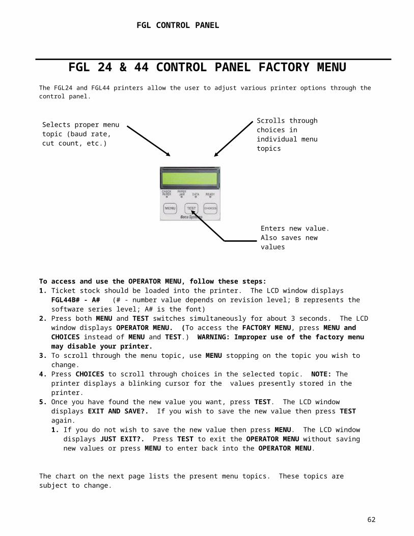
BI-DIRECTIONAL PARALLEL MODE ENABLED/DISABLED COMMANDS - <bpe>/<bpd>Note: This function should only be used by an experienced user.These commands set the printer up for bi-directional parallel <bpe> or non- bi-directional parallel <bpd> communication.
TEXT TICKET TYPE COMMANDS - <tst#>/<TST#>These commands set the test ticket type that is printed off the test button. The values can range as shown below:
0 – standard test ticket1 – configuration 1 ( for 1 inch ticket)2 – configuration 2 ( for 2 inch ticket)3 – configuration 3 ( for 3 inch ticket)4 – configuration 4 ( for 4 inch ticket)6 – continuous test tickets
NOTE: The lowercase <tst#> commands sets the test ticket type in flash. The uppercase <TST#> command sets the test ticket type until power is turned off. It will also print a test ticket without having to press the test button.
BASEBALL MODE COMMAND - <bm#>Note: This function is set at the factory and should not be changed.This command sets the baseball mode for the printer. The values can range as shown below:
0 – No baseball mode.1 – Dodgers2 – Mets3 – Twins
USB (UNIVERSAL SERIAL BUS) ENABLED/DISABLED COMMANDS - <eusb>/<dusb>Note: This function should only be used by an experienced user.These commands enable or disable the printer for USB communication.
FONT ENCODING COMMAND - <fe#>Note: This function should only be used by an experienced user.This command sets the font encoding used with special two-byte character fonts.
0 – None (default)1– EUC-8 2 – EUC-73 – UNICODE-14 – UNICODE-25 – BIG-56 – YANGJAE (obsolete)7 – SJIS8 – GBK (not available on FGL42 series).
ACKNOWLEDGE COMMAND - <akn>/<akd>Note: This function should only be used by an experienced user.Defines when the end of print acknowledgment is sent out by the printer. In normal mode <akn>, the ACK is sent after printing is completed but before any other action like cutting is performed. So if the cutter failed or ticket jammed the printer would still send an ACK indicating the ticket was printed. In addition, the printer would send an error message indicating the failure. In delayed mode <akd>, the ACK is sent after the entire printing operation completes successfully. You would not receive an ACK if there was a failure.
HIGH SPEED MODE ENABLED/DISABLED COMMAND- <hie>/<hid> Note: This feature is set at the factory and should not be changed.Only used on printers with a special pulley ratio to allow high speed printing.
BUZZER ENABLED/DISABLED COMMAND- <bz#>/<BZ#>Only used on printers with a paper out buzzer. The values can range as shown below:1-no buzzer
62

2- sound buzzer every 15s.3- sound buzzer every 30s.4- sound buzzer every 45s.
SHUFFLE MODE ENABLED/DISABLED COMMAND - <sfe>/<sfd>This feature should normally be disabled.Shuffles the ticket every 15 minutes when the printer is inactive.
CUTTER TYPE COMMAND - <mct#>Note: This function is set at the factory and generally should not be changed.This command sets the cutter type for a Mini printer.
0 – Silent1– Boca
CUTTER SPEED COMMAND - <mcs#>Note: This function is set at the factory and generally should not be changed.This command sets the cutter speed for a Boca cutter.
0 – Normal1– Slow
ORIENTATION NORMAL/REVERSE COMMAND - <rte>/<rtd> Defines the orientation of the ticket portrait mode layout. The normal default mode is disabled <rtd>. Reverse <rte> will rotate the ticket portrait mode layout 180. This will only work in conjunction with the boca print driver. It is intended to make the Boca print driver compatible with the HP Laserjet IIP print driver. Please consult the PRINTER DRIVER SUPPLEMENT for additional information.
MAGNETICS COMMANDS………….
MAGNETICS MODE ENABLED/DISABLED COMMANDS - <mme>/<mmd>These commands set the printer in magnetics mode <mme> or non-magnetics mode <mmd> after initializing.
Note: the following commands are valid for magnetic printers only.
MAGNETICS TICKET LENGTH COMMAND - <mtl#>Note: This function should only be used by an experienced user.This command sets the magnetic ticket length. The values can range as shown below:
1 – 3.375”2 – 4.0”
MAGNETICS PRINTER STYLE COMMAND - <mps#>Note: This function should only be used by an experienced user.This command sets the magnetics printer style. The values can range as shown below:
1 – Normal2 – Long3 – Switches
ADJUST REVERSE COUNT COMMAND - <mrc#>Note: This function should only be used by an experienced user.This command adjusts the amount the printer reverses to start printing. The value range depends on the Magnetic Printer Style. For a Switch Style Printer it is 180 +/- 7. Otherwise, it is 70 +/- 7.
INC/DEC BURST COUNT COMMAND – <bc#>63

Note: This function should only be used by an experienced user and is only applicable to mag printers.This command sets the burst count for the burster. Before sending this command, the user must identify the ticket length value stored in the printer. The burst count value can then be set within +/-75 of the ticket length.
AUTO REPRINT ENABLED/DISABLED COMMANDS - <mre>/<mrd>Note: This function should only be used by an experienced user.These commands enable <mre> or disable <mrd> the auto reprint function for the magnetics printer.Note: selecting the auto reprint function automatically disables the purge on void function below.
PURGE ON VOID ENABLED/DISABLED COMMANDS - <mpe>/<mpd>Note: This function should only be used by an experienced user.These commands enable <mpe> or disable <mpd> the purge on void function for the magnetics printer.Note: selecting the purge on void function automatically disables the auto reprint function above.
MAGNETICS TYPE COMMAND - <mty#>Note: This function is set at the factory and should not be changed.This command sets the type of magnetic printer. The values can range from 1-4 as shown below:
1 – bottom2 – top3 – center4 – mini kiosk
TRACK SELECTION COMMAND - <mts#>Note: This function should only be used by an experienced user.This command sets the track selection for the printer. The values can range from 1-5 as shown below:
1 – tracks 1/2/32 – tracks 1/23 – track 14 – track 25 – disabled
TRACK 2 DENSITY COMMAND - <mtd#>Note: This function should only be used by an experienced user.This command sets the track 2 density. The values can range from 1-2 as shown below:
1 – 75 bpi2 – 210 bpi
TRACK ENCODING COMMAND - <mte#>Note: This function should only be used by an experienced user.This command sets the track encoding. The values can range from 1-2 as shown below:
1 – 7/5/52 – 7/7/7
ETHERNET COMMANDS………….
ETHERNET MODE COMMAND - <eth#>This command sets the Ethernet mode for the printer and is permanently stored in flash. The values can range as shown below:
0 – Ethernet Interface disabled64

1 – Ethernet Interface enabled2 – Ethernet Diagnostic Mode - (prints all packets transmitted or received by the printer).3 – Ethernet Diagnostic Valid Packet Mode - (prints only valid packets transmitted or received by the printer).4 – DHCP Enabled (automatically attempts to get an IP address from Local Server).
Notes: Ethernet Diagnostic Modes should only be used after consulting with Boca Systems.
The DHCP enabled function will cause the printer to automatically attempt to retrieve a ‘permanent’ IP address from a Local Server after powering on. If the server does not assign a ‘permanent’ one, then it will allocate an address for a limited period of time (lease time). If this is the case, the printer will automatically try and renew its lease before it expires. If DHCP is enabled, but no response is received from a Local Server in time, the printer will revert back to its default IP. For convenience, the printer’s IP address is now printed on the Test Ticket.
PERMANENT PROTOCOL ADDRESS COMMAND - <ip10.0.1.25>This command permanently changes the IP address of the printer and stores it in flash. The example above would change the address to 10.0.1.25. The default address is 10.0.0.192.
PERMANENT DEFAULT GATEWAY IP ADDRESS COMMAND - <dgw10.0.1.254>Note: This function should only be used by an experienced user.This command permanently changes the IP address of the default gateway and stores it in flash. The example above would change the address to 10.0.1.254. The default address is 10.0.0.192. Note: the subnet value must be non-zero in order for the Gateway Address to be valid (see below).
PERMANENT SUBNET MASK COMMAND - <sub#>Note: This function should only be used by an experienced user.This command permanently changes the Subnet Mask for the network and stores it in flash. The default mask is 0 (0.0.0.0). This is a reserved value and is used by the printer to indicate there is no subnet. Thus the printer will treat all packets as if they are on a ‘direct route’. If you want packets sent to the Gateway Address you must assign one of the following non-zero values (1-32):
0.0.0.0 (reserved) 17 255.255.128.0 (class C)128.0.0.0 (class A) 18 255.255.192.0 “192.0.0.0 “ 19 255.255.224.0 “224.0.0.0 “ 20 255.255.240.0 “240.0.0.0 “ 21 255.255.248.0 “248.0.0.0 “ 22 255.255.252.0 “252.0.0.0 “ 23 255.255.254.0 “254.0.0.0 “ 24 255.255.255.0 “255.0.0.0 “ 25 255.255.255.128255.128.0.0 (class B) 26 255.255.255.192255.192.0.0 “ 27 255.255.255.224255.224.0.0 “ 28 255.255.255.240255.240.0.0 “ 29 255.255.255.248255.248.0.0 “ 30 255.255.255.252255.252.0.0 “ 31 255.255.255.254 (unusable)255.254.0.0 “ 32 255.255.255.255 (host-single address)255.255.0.0 “
Note: If a Subnet Mask and Gateway Address have been provided, the printer will attempt to obtain the Gateway’s MAC address (using the ARP protocol) during initialization of the printer. If it is unable to establish communication with the Gateway after a number of tries, it will treat the Gateway as a ‘Dead Gateway’. In this case, all packets meant for the Gateway will be silently discarded. If the Gateway’s MAC address is obtained, then that ‘indirect route’ will be used for all off-network packets. The MAC address will be ‘persistent’ until the printer is reset or power cycled.
65

ETHERNET PORT CONFIGURATION - <epc#> Available in versions FGL44B28 and above.Normally, the printer will auto-negotiate its port configuration with the network. Some customers have asked for the ability to manually set the speed and duplex settings of the Ethernet port. This command permanently stores the selected port settings in flash. The values (#) can range as shown below:
0 – Auto-negotiate1 - 100 Mbps/Full duplex2 - 100 Mbps/Half duplex3 - 10 Mbps/Full duplex4 - 10 Mbps/Half duplex
ADDITIONAL ITEMS PRINTED ON THE CONFIGURATION TICKET MAY INCLUDE THE FOLLOWING:
Firmware revisionCommon code revisionFont nameSerial numberControl panel enabledTest button enabledTicket length in dotsPrinting length in dotsPrinting width in dotsPrint head sizeLptix (lines per ticket)Top offsetBottom offsetLeft offsetOffsets enabledEx. Memory enabledDownload space availableMaximum free flash (this equals the amount of free bytes plus dirty bytes. Note: Need a reclaim to use dirty bytes)Maximum free ram (largest block available)Ticket countStatus commandsStorage mode (permanent, temporary)Communication buffer sizeCode page (normal,437,850,852,1252)Dual cutterMini sync enabledLow voltage settingStepper hold countPermanent TC (ticket count)Re-settable TCMAC AddressGateway MAC AddressOn TimeIdle TimeoutRetransmit Timeout
66

CHANGING ETHERNET ADDRESS SUPPLEMENT
Please follow the enclosed steps to change the addresses on your Ethernet printer.
Changing IP Address
1. Depress both the MENU and CHOICES buttons while turning on the printer. Keep both buttons depressed unit FACTORY MENU appears in the LCD window or the display starts scrolling through different topics.
2. Using the MENU button scroll down to the IP ADDRESS? topic and press the CHOICE button.
3. The blinking cursor indicates the current IP numeric value selected. Every time you press the CHOICE button the numeric value will change.
4. Using the TEST button will move you over to the next numeric value.
5. Continue steps 3 & 4 to program the desired IP address value.
6. At the end the display will show EXIT AND SAVE. Press the TEST button to save the IP address you just entered.
Changing Default Gateway address
Follow same procedure as above but in step 2 scroll down to the DEFAULT GATEWAY topic.
Changing Subnet Mask address
1. Depress both the MENU and CHOICES buttons while turning on the printer. Keep both buttons depressed unit FACTORY MENU appears in the LCD window or the display starts scrolling through different topics.
2. Using the MENU button scroll down to the Subnet Mask? topic and press the CHOICE button.
3. Each time you press the CHOICE button a different address will be displayed.
4. Once you have the address you want, press the TEST button. The display will show EXIT AND SAVE. Press the TEST button a second time to save the address value.
67

ETHERNET INTERFACE ADDENDUM - REV D
ETHERNET – Quick Installation Guide
Connect the printer to your network (the IP address will be automatically assigned by your DHCP server)
Load tickets into the printer Wait one minute to allow assignment of IP address Print a test ticket to identify the printer's IP address Ping the printer Open your web browser and type the printer’s IP address to review its configuration If you experience any problems, please refer to the Ethernet Interface Addendum or email
Boca Printers running firmware version FGL44B and higher are capable of supporting an Ethernet interface. A standard RJ-45 connector is used to connect the printer to the network. The interface has been tested on both 10base-T and 100Base-TX networks.
Important new information:Each Boca Ethernet Printer is assigned a unique MAC address based in part on the printer’s serial number. Prior to April, 2006 all Boca Ethernet printers were shipped with a fixed default IP address of 10.0.0.192. After that date, they were shipped as DHCP enabled printers. If the printer is unable to get a dynamic IP address from the customer’s network in the allotted time period (about one minute) it will then default to the 10.0.0.192 address. If the customer wants to set a different fixed IP address, they must change the ‘ETHERNET’ setting on the printer from ‘DHCP ENABLED’ to ‘YES’ and then set the ‘IP ADDRESS’. These options can be changed by using the Web or Control Panel Configuration methods or by sending the appropriate FGL commands. These methods are described in the next section.
Note: for reference, the printer’s IP address is printed on the test ticket. If using DHCP, it may take up to one minute to obtain a valid IP address. Until then, it will display all zeros on the test ticket.
While Boca does not support every Ethernet protocol, the printer supports a sufficient number of high level protocols to function effectively as a network printer. Below is a list of supported and non-supported features of the printer. More support may be added in the future as needed.
SUPPORTED PROTOCOLS (must use default port values).CATEGORY SUPPORTED FEATURE UNSUPPORTED FEATUREFrames Ethernet version 2 IEEE 802.3Ping Number of echo requests Loose source route along host - list
Buffer size Strict source route along host - listRecord routeTime to liveTimestamp
ARP ARP request RARP requestARP response RARP response
Dynamic RARP requestDynamic RARP responseInARP requestInARP reply
ICMP Echo Destination UnreachableEcho Reply Source QuenchParameter Problem Redirect
Time ExceededTimestampTimestamp ReplyInformation RequestInformation ReplyAddress Mask Request
68

Address Mask ReplyIpv4 Internet Timestamp Loose Source and Record Route
Record Route Strict Source and Record RouteStream Identifier Fragmented IP packetsSecurity - all levels accepted
TCP MSS All others (SACK, echo, etc.)HTTP GET, POST HEADUDP Supports DHCP datagrams Presently no other UDP datagramsDHCP Automatic or Dynamic IP allocation DHCP Release, DHCP Inform
Unsupported Protocols IPv6, SNMP, DNS, SMTP, TFTP, FTP, TELNET, IPP, DLC
Network ports (port monitors) supported:Works with Microsoft Standard TCP/IP port - SNMP disabledWorks with HP Standard TCP/IP port - SNMP disabledWorks with Microsoft LPR port
PING UTITITYYou can use the MS-DOS Ping command for diagnostic testing and to verify the network connection.
ping 10.0.0.192 will ping the network printer 10.0.0.192 four times.
NETWORK INTERFACES supported under TCP/IP
SUPPORTED INTERFACE COMMENTSWindows Socket API Bi-directional Raw TCP protocol between printer and Host (port 9100)LPD/LPR Unidirectional LPD protocol data to printer (port 515)
All commands supported except “remove jobs”
UNSUPPORTED INTERFACE COMMENTSAPP Socket Raw TCP protocol data from Host to printer (port 9100)
Status returned to Host as UDP data on Port 9101
RAW TCP OPERATIONTCP communication is initiated by opening the connection (item 1) and terminated by closing the connection (item 4). Item 2 is necessary to print tickets. The printer can return status data (item 3) either in response to an external status request or as a result of a change in printer status. Each item below must be completed with the indicated acknowledgement. In the event that the item is not completed, the printer may initiate a timeout to close the port and discontinue the application (see Retransmit Command Timeout). In the event that the connection remains open for an excessive amount of time, the printer may reset the connection and discontinue the application if another application requests service (see Idle Timeout Command).
1. Host opens the connection / Printer acknowledges / Host acknowledges2. Host sends data / Printer acknowledges3. Printer sends data / Host acknowledges (RAW TCP only)4. Host closes the connection / Printer acknowledges / Host acknowledges
Please note that the printer will only allow one open connection at a time. Normally, an application will open a connection and close it after the ticket data has been sent and all status has been received. Any other applications requesting a connection will be refused until the original connection has been closed or the idle timeout period has expired.
WEB CONFIGURATION:The printer can be configured across the network by typing in its IP address in the Address Bar of a Web Browser. It will allow you to set the same configuration options available under the control panel Factory Menu.
69

CONTROL PANEL CONFIGURATION:
Changing ‘ETHERNET’ setting
2. Please follow these steps to change the ETHERNET setting on your Ethernet printer. 3. Depress both the MENU and CHOICES buttons while turning on the printer. Keep both buttons
depressed unit FACTORY MENU appears in the LCD window or the display starts scrolling through different topics.
4. Using the MENU button scroll down to the ETHERNET? topic and press the CHOICE button.
5. The blinking cursor indicates the current setting selected. Every time you press the CHOICE button the setting option will change.
6. Choose the appropriate setting. Select ‘DHCP ENABLED’ for dynamic addressing or ‘YES’ for using a fixed IP address.
7. Press the TEST button to enter that setting.
8. Now the display will show EXIT AND SAVE. Press the TEST button to save the setting entered.
9. Note: if you selected ‘YES’ then you can use the default IP of 10.0.0.192 or set a different one as described next.
Changing ‘IP ADDRESS’
1. Please follow these steps to change the fixed IP address on your Ethernet printer. Note: if using a fixed IP address make sure the ‘ETHERNET’ setting is set to ‘YES’ (see above).
2. Depress both the MENU and CHOICES buttons while turning on the printer. Keep both buttons depressed unit FACTORY MENU appears in the LCD window or the display starts scrolling through different topics.
3. Using the MENU button scroll down to the IP ADDRESS? topic and press the CHOICE button.
4. The blinking cursor indicates the current IP numeric value selected. Every time you press the CHOICE button the numeric value will change.
5. Using the TEST button will move you over to the next numeric value.
6. Continue steps 4 & 5 to program the desired IP address value.
7. At the end the display will show EXIT AND SAVE. Press the TEST button to save the IP address you just entered.
70
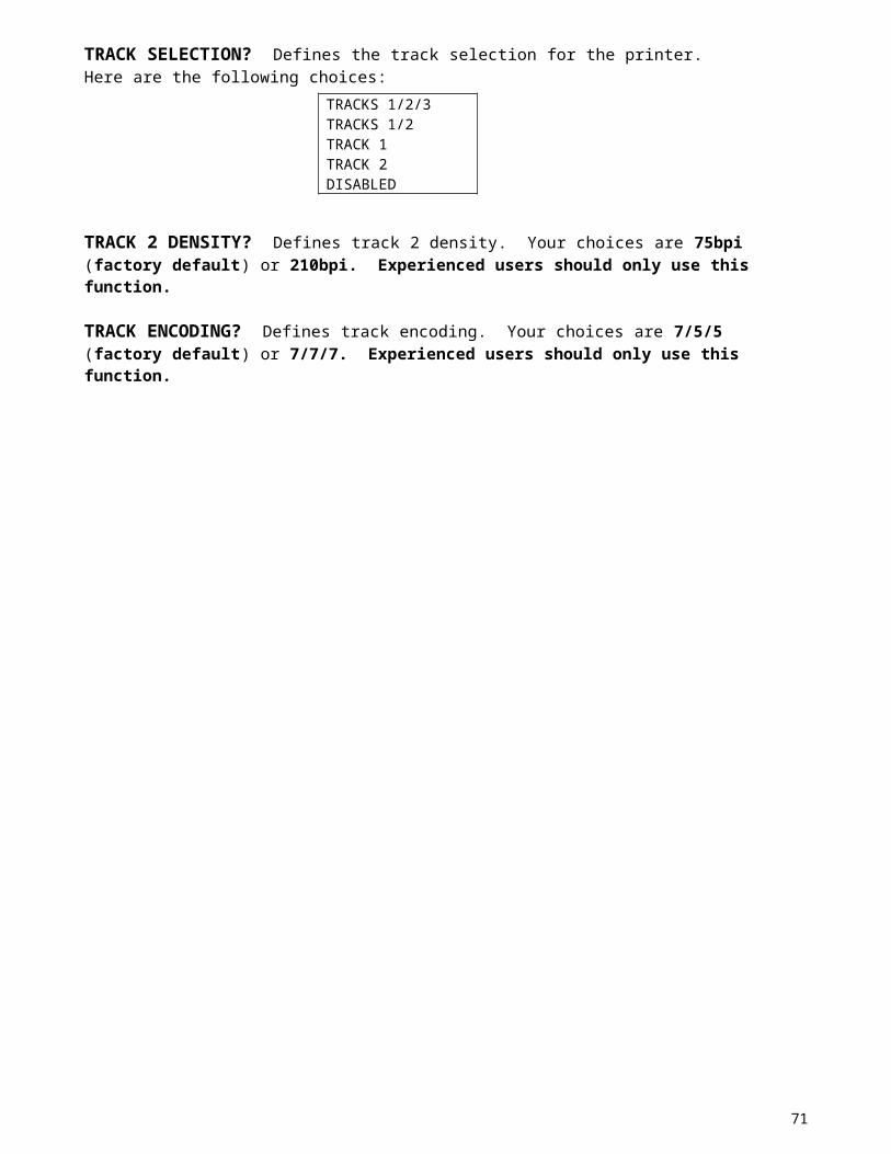
FGL NETWORKING COMMANDS:
ETHERNET MODE COMMAND - <eth#>This command sets the Ethernet mode for the printer and is permanently stored in flash. This can also be set using the 'Factory Menu'. The values can range as shown below:
0 – Ethernet Interface disabled1 - Ethernet Interface enabled2 - Ethernet Diagnostic Mode - (prints all packets transmitted or received by the printer).3 - Ethernet Diagnostic Valid Packet Mode - (prints only valid packets transmitted or received
by the printer).4 – DHCP Enabled (automatically attempts to get an IP address from Local Server).
Notes: Ethernet Diagnostic Modes should only be used after consulting with Boca Systems.
The DHCP enabled function will cause the printer to automatically attempt to retrieve a ‘permanent’ IP address from a Local Server after powering on. If the server does not assign a ‘permanent’ one, then it will allocate an address for a limited period of time (lease time). If this is the case, the printer will automatically try and renew its lease before it expires. If DHCP is enabled, but no response is received from a Local Server in time, the printer will revert back to its default IP. For convenience, the printer’s IP address is now printed on the Test Ticket.
MEDIA ACCESS CONTROL NUMBER COMMAND - <MAC>This command returns the MAC number (Ethernet address) for the printer in the form ##.##.##.##.##.##. The MAC is used by hardware devices on the network to communicate with each other. It is set at the factory and can’t be changed by the user.
INTERNET PROTOCOL ADDRESS COMMAND - <IP>This command returns the IP address of the printer in the form ###.###.###.###. The IP address is used by applications on ‘direct’ networks to communicate with each other. The default address is 10.0.0.192. This address can be changed by the user. See next command.
PERMANENT PROTOCOL ADDRESS COMMAND - <ip10.0.1.25>This command permanently changes the IP address of the printer and stores it in flash. The example above would change the address to 10.0.1.25. The IP address can also be changed using the ‘Factory or Web Menu’. The default address is 10.0.0.192. Note: IP address 0.0.0.0 is reserved.
IDLE TIMEOUT COMMAND - <idt#>This command permanently stores the timeout value (#) in flash. The value (#) can range from 1-65535 seconds. The printer will reset the open connection after # seconds of inactivity if another application is seeking to communicate with the printer. In this case, a reset (RST packet) will be sent to the open connection, and any previously stored data will be flushed. The default setting is 30 seconds.
RETRANSMIT TIMEOUT COMMAND - <rtt#>This command permanently stores the Retransmit Timeout value in flash. The value (#) can range from 1-65535 seconds. This command sets the total timeout period for a network port connection to remain open if there is a problem communicating between ports. Normally, after 2s, the Boca printer will retransmit data that has failed to be acknowledged by the Host TCP. Then it will wait 4s, then 8s, etc. After a total of 300s, the Boca will send a RST packet and terminate the connection. Any previously stored data will be flushed. The default setting is 300 seconds.
NEW FGL NETWORKING COMMANDS: Available in versions FGL44B5 and above.
Previous firmware versions did not allow you to assign a subnet mask or default gateway. The printer would always send packets directly to the destination host. This would work on all directly connected networks. This is referred to as a ‘direct route’. Sometimes it is necessary to run the printer on an indirectly connected network. It must send its responses through a gateway in order to reach the destination host. Therefore, we have added the Subnet Mask and Default Gateway commands to the printer. They can also be set through the control panel and Web Menus.
71

DEFAULT GATEWAY MEDIA ACCESS CONTROL NUMBER COMMAND - <DGM>This command returns the MAC number (Ethernet address) for the Default Gateway in the form ##.##.##.##.##.##. The MAC is used by hardware devices on the network to communicate with each other. The Gateway MAC is obtained during initialization (see Note under Permanent Subnet Mask command). DEFAULT GATEWAY IP ADDRESS COMMAND - <DGW>This command returns the IP address of the Default Gateway in the form ###.###.###.###. The Gateway IP number is used by applications on ‘indirect’ networks to communicate with each other. The default address is 10.0.0.192. This address can be changed by the user (see below).
PERMANENT DEFAULT GATEWAY IP ADDRESS COMMAND - <dgw10.0.1.254>Note: This function should only be used by an experienced user.This command permanently changes the IP address of the default gateway and stores it in flash. The example above would change the address to 10.0.1.254. The Gateway Address can also be changed using the ‘Factory or Web Menu’. The default address is 10.0.0.192. Note: the subnet value must be non-zero in order for the Gateway Address to be valid (see below).
SUBNET MASK COMMAND - <SUB>This command returns the Subnet Mask for the network in the form ###.###.###.###. The Subnet Mask is used by the printer to determine if the destination is on a connected network (direct route). If not, it is sent to the Gateway Address. The default mask is 0 (0.0.0.0). This value can be changed by the user. Do not change the Subnet Mask from zero unless you are using a Gateway. See next command.
PERMANENT SUBNET MASK COMMAND - <sub#>Note: This function should only be used by an experienced user.This command permanently changes the Subnet Mask for the network and stores it in flash. The Subnet Mask can also be changed using the ‘Factory or Web Menu’. The default mask is 0 (0.0.0.0). This is a reserved value and is used by the printer to indicate there is no subnet. Thus the printer will treat all packets as if they are on a ‘direct route’. If you want packets sent to the Gateway Address you must assign one of the following non-zero values (1-32):
0 0.0.0.0 (reserved) 17 255.255.128.0 (class C)1 128.0.0.0 (class A) 18 255.255.192.0 “2 192.0.0.0 “ 19 255.255.224.0 “3 224.0.0.0 “ 20 255.255.240.0 “4 240.0.0.0 “ 21 255.255.248.0 “5 248.0.0.0 “ 22 255.255.252.0 “6 252.0.0.0 “ 23 255.255.254.0 “7 254.0.0.0 “ 24 255.255.255.0 “8 255.0.0.0 “ 25 255.255.255.1289 255.128.0.0 (class B) 26 255.255.255.19210 255.192.0.0 “ 27 255.255.255.22411 255.224.0.0 “ 28 255.255.255.24012 255.240.0.0 “ 29 255.255.255.24813 255.248.0.0 “ 30 255.255.255.25214 255.252.0.0 “ 31 255.255.255.254 (unusable)15 255.254.0.0 “ 32 255.255.255.255 (host-single address)16 255.255.0.0 “
Note: If a Subnet Mask and Gateway Address have been provided, the printer will attempt to obtain the Gateway’s MAC address (using the ARP protocol) during initialization of the printer. If it is unable to establish communication with the Gateway after a number of tries, it will treat the Gateway as a ‘Dead Gateway’. In this case, all packets meant for the Gateway will be silently discarded. If the Gateway’s MAC address is obtained, then that ‘indirect route’ will be used for all off-network packets. The MAC address will be ‘persistent’ until the printer is reset or power cycled. Do not change the Subnet Mask from zero unless you are using a Gateway.
ETHERNET PORT CONFIGURATION - <epc#> Available in versions FGL44B28 and above.
72

Normally, the printer will auto-negotiate its port configuration with the network. Some customers have asked for the ability to manually set the speed and duplex settings of the Ethernet port. This command permanently stores the selected port settings in flash. The values (#) can range as shown below:
0 – Auto-negotiate1 - 100 Mbps/Full duplex2 - 100 Mbps/Half duplex3 - 10 Mbps/Full duplex4 - 10 Mbps/Half duplex
Using the Ethernet InterfaceYou can configure the Ethernet interface to communicate with your printer either directly across the network or as a shared device attached to a specific computer. Below are some of the options available in a Windows 2000 environment. Most of these should also be available under Windows XP. Other operating systems (like UNIX) should have similar capabilities to the ones shown below.
NETWORK INTERFACES
.WINDOWS SOCKET APIThe use of Windows Socket API calls allows the user bi-directional communication across the network and full control of the process. A sample freeware program called Netcat works with the printer and can be used as is, modified or referred to as a guideline for writing your own program.
.DOS COMMANDSLPR and LPQ commands allow the user to talk directly to the printer across the network.
LPR - prints a file to any network device (BOCA printer) running an LPD server lpr -SServer -PPrinter [-CClass] [-JJobname] [-O option] filename
Parameters-SServer > Specifies the name or IP address of the computer or the print device running LPD.-PPrinter > Specifies the name of the printer for the desired queue.-CClass > Specifies the content of the banner page for the class.-JJobname > Specifies the name of this job.-O option > Indicates the type of file. The default is a text file. Use -Ol (lowercase 'L') for a binary file (for example, PostScript).filename > The name of the file to be printed.ex. lpr -S10.0.0.192 -Pboca p.txt Sends the file p.txt to the printer with IP address 10.0.0.192
LPQ - requests printer status lpq -SServer -PPrinter [-l]
Parameters-SServer > Specifies the name of the computer or print device running LPD.-PPrinter > Specifies the name of the printer for the desired queue.-l (Lowercase L) > Specifies that a detailed status should be given.
Note: specifying the command without the lowercase L returns a generic printer ok status message if the printer is not busy (see below). However, the printer will not accept the command if it is busy, so nothing is usually returned until the printer is ready again.
ex. lpq -S10.0.0.192 -Pboca Normally returns a ‘Boca Systems lpd: no jobs queued on this port’ message (printer ok).
ex. lpq -S10.0.0.192 -Pboca -l Returns detailed status for boca queue print job on printer with IP address 10.0.0.192. Note: this will include all of the printer status bytes described in the ‘Printer Status Supplement’ in the programming guide.
.SHARED DEVICE
73
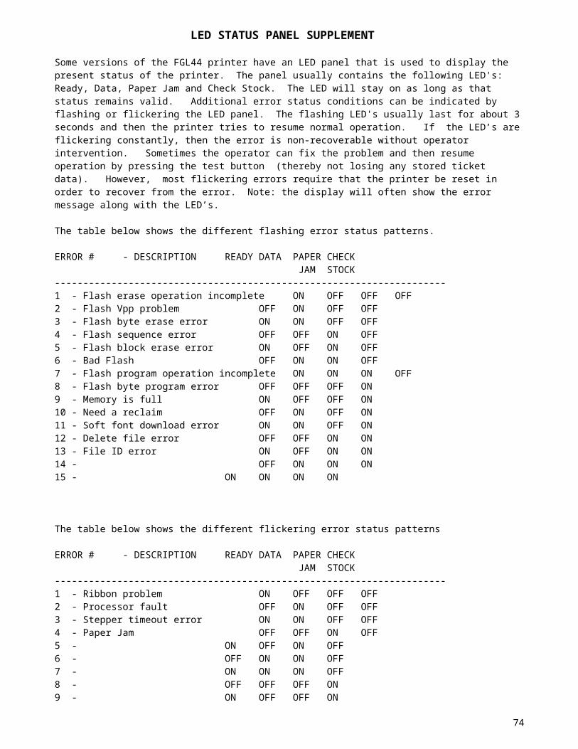
The printer may be installed as a shared device on a Network Port using either an LPR port or a Standard TCP/IP port (See installation instructions at the end of this document). As a shared device, it is possible to redirect one of the LPT# ports to a network port allowing all of Boca's sample VB, VC, 'C' and GWBasic programs to work across the network. Redirection is accomplished by using the MS-DOS command Net Use. Choose a port name on your PC that is not being used (such as LPT2:). The syntax of the command is:
Net Use LPT2: \\networkPCname\printersharename ex. Net Use LPT2: \\panther\tcpprint
At this point, any copy command issued to LPT2: on your PC will be redirected across your network to the Boca Systems Inc. printer named tcpprint attached to PC panther. Although the printer can be written to across the network by this method, the data returned from the printer can't be read back. For further details on Net Use, refer to your DOS manual or use Windows Help mode.
74

Ethernet Trouble-shooting guide....
MAC conflicts:
You must make sure there are no MAC address conflicts between multiple Boca Printers and any other devices on your network. Though it should never be the case, there was once an instance where two Boca Printers had the same MAC. The printer’s MAC address is based on its serial number. Changing the printer’s serial number might cause a problem.
Packet loss:
Determine if you are losing packets. To test for packet loss, ping the printer 1000 times. Use the ‘ping –n 1000 –l 1472 printers IP address’ command. Let us know how many packets are lost. We have found that if a customer is losing a lot of packets (more than 10) we may be able to improve this by shortening the internal ribbon cable to the Ethernet card. Note: the –l 1472 parameter in the ping command tests the Maximum Transmission Unit (MTU) of the network. It should be able to handle IP datagrams up to 1472 bytes.
LPR vs RAW TCP:
If you are having a problem using LPR mode make sure the 'byte counting enabled' option is set. Try running in RAW TCP mode or vice versa.
Windows Driver vs Windows Socket API:
Are you using a Windows Driver or writing directly to the printer using Windows Socket API calls? Try both approaches if possible and see if one is better than the other.
Printer Timeout issues:
Is the printer timing out during the retransmission of a packet or in an idle state? Try playing with the following commands to see if it improves performance. The commands are explained above.
IDLE TIMEOUT COMMAND - <idt#>
RETRANSMIT TIMEOUT COMMAND - <rtt#>
Host Timeout issues:
Please refer to the following Microsoft Articles for possible solutions.
‘How to Modify the TCP/IP Maximum Retransmission Timeout’ - Article: 170359
‘TCP/IP Port Printing May Be Slow on Windows 2000’ - Article ID: 816627
‘TCP/IP and NBT configuration parameters for Windows 2000 or Windows NT’ - Article ID: 120642
Monitor traffic:
Are you able to monitor the Ethernet traffic between the Host and printer? Can you determine if the printer is not responding to a particular packet or is going busy? Is it losing packets? Can you send us a copy of the packet traffic at the point it fails?
75

Problem printing large batches of tickets:Try changing your system so it does not create a new print job for every ticket. In this case, the printer works better and faster. Try to limit the number of jobs opened and closed. You can also try sending a large batch of tickets in a series of smaller batches. If possible, hook up an HP Jetdirect Print Server to the printer (requires a parallel port) and see if the problem still exists. If so, it is probably a Network issue on the client’s end (likely a bandwidth, configuration, slow link or router problem).
Client Network Problems:Several clients had problems initially but they turned out to be networking issues on their end (bandwidth problems, configuration settings, etc). Make sure everything is configured correctly on the Network.
Auto-Negotiate problem:One client had an issue where his switches would not auto-negotiate correctly with the printer. Try manually setting your switches to 100 Mbps, Full duplex.
76

Installation of port monitor instructions:
Note: Please make sure you have either the HP LaserJet llP Plus Print driver or the appropriate Boca FGL Print driver installed before continuing with these instructions (see website for FGL driver).
Installing a Standard TCP/IP port using Raw protocol on Windows 2000 (preferred method).1. Open the Control Panel through the Start Menu and open Printers. 2. Double click Add Printer.3. Click Next. 4. Select Local printer, clear the Automatically detect my printer check box, and then click Next. 5. Select Create a new port. 6. Choose Standard TCP/IP Port from the "Type" drop down menu. You may have to scroll all the way down to the bottom. 7: Click Next. 8: Enter the IP address of the printer into the Printer Name or IP Address field (ex. 10.0.0.192). The Port Name is filled in automatically. You may change it if you wish.9: Enter the name you wish to call the printer in the Port Name field (ex. BOCA). 10. Click Next and wait for a bit. 11. Set Device Type to Custom and click Settings. 12. Set Protocol to Raw. 13. Make sure Port Number is set to 9100. 14. Leave SNMP Status Enabled unchecked.15. Click OK, then click Next, then click Finish and wait a bit. 16. Choose Boca-> appropriate dpi version and click Next. Choose HP -> HP laserJet llP Plus if using a PCL4 BOCA printer.17. If it tells you the driver is already installed, keep existing driver and just click Next. 18. Enter the name you wish to call the printer in the Printer Name field (ex. tcpprinter). Decide if you want it as your default printer.19. Click Next. 20. Decide if you want to share the printer - if so, give it a 'share' name (ex. tcpprint).21. Click Next.22. Give it a location/comment description if desired.23. Click Next.24. Select No or Yes for Do you want to print a test page? 25. Click Next and then click Finish. 26. If you elected to print a test page it should print after clicking Finish.
Note: The Standard TCP/IP port (shown above) is the only method we support which allows for detailed status to be reported back to the Host via the bi-directional Raw TCP protocol.
Installing an LPR port on Windows 2000.1. To open Printers, click Start, point to Settings, and then click Printers.2. Double-click Add Printer, and then click Next. 3. Click Local printer, clear the Automatically detect my printer check box, and then click Next. 4. Click Create a new port, and then click LPR Port. If LPR Port is not available, click Cancel to stop the wizard. To add the LPR port, you need to install Print Services for Unix. 5. Click Next, and then provide the following information: - In Name or address of server providing LPD, type the DNS name or Internet Protocol (IP) address of the host for the printer you are adding. You can also enter the DNS name or IP address of the direct-connect TCP/IP printing device (the boca printer) or the UNIX computer to which the printing device is connected (ex. 10.0.0.192). The DNS name can be the name specified for the host in the Hosts file. - In Name of printer or print queue on that server, type the name of the printer as it is identified by the Host, which is either the direct-connect printer itself or the UNIX computer.6. Choose Boca-> appropriate dpi version and click Next. Choose HP -> HP laserJet llP Plus if using a PCL4 BOCA printer.7. If it tells you the driver is already installed, keep existing driver and just click Next. 8. Enter the name you wish to call the printer in the Printer Name field (ex. lprprinter). Decide if you want it as your default printer.9. Click Next. 10 Decide if you want to share the printer - if so, give it a 'share' name (ex. lprprint).11. Click Next.12. Give it a location/comment description if desired.13. Click Next.14. Select No or Yes for Do you want to print a test page? 15. Click Next and then click Finish. 16. If you elected to print a test page it should print after clicking Finish.
Notes:
77

.The LPR port is best suited to servers that need to communicate with host computers such as UNIX or VAX machines by way of RFC 1179..For computers that need to submit print jobs to host computers, the standard TCP/IP port (see above) should be used in most cases. .The LPR port only allows limited printer status to be reported to the Host. A generic error condition is reported when something goes wrong like a paper jam or paper out.
Installing a Standard TCP/IP port using simplified LPR protocol on Windows 2000.1. Open the Control Panel through the Start Menu and open Printers. 2. Double click Add Printer.3. Click Next. 4. Select Local printer, clear the Automatically detect my printer check box, and then click Next. 5. Select Create a new port. 6. Choose Standard TCP/IP Port from the "Type" drop down menu. You may have to scroll all the way down to the bottom. 7: Click Next. 8: Enter the IP address of the printer into the Printer Name or IP Address field (ex. 10.0.0.192). The Port Name is filled in automatically. You may change it if you wish.9: Enter the name you wish to call the printer in the Port Name field (ex. BOCA). 10. Click Next and wait for a bit. 11. Set Device Type to Custom and click Settings. 12. Set Protocol to LPR. 13. Enter the name you wish to call the printer in the Queue Name field. 14. Check the LPR Byte Counting Enabled check box.15. Leave SNMP Status Enabled unchecked.16. Click OK, then click Next, then click Finish and wait a bit. 17. Choose Boca-> appropriate dpi version and click Next. Choose HP -> HP laserJet llP Plus if using a PCL4 BOCA printer.18. If it tells you the driver is already installed, keep existing driver and just click Next. 19. Enter the name you wish to call the printer in the Printer Name field (ex. lprprinter). Decide if you want it as your default printer.20. Click Next. 21. Decide if you want to share the printer - if so, give it a 'share' name (ex. lprprint).22. Click Next.23. Give it a location/comment description if desired.24. Click Next.25. Select No or Yes for Do you want to print a test page? 26. Click Next and then click Finish. 27. If you elected to print a test page it should print after clicking Finish.
Notes:The simplified LPR protocol differs from an RFC 1179 compliant LPR port in that it only supports the printer implementations of LPR. A machine running an LPD service (like a UNIX box) cannot be designated as the destination. Only LPD capable printers can be the destination for print jobs. The simplified LPR protocol can use non-RFC source port addresses (other than 721-731). Simplified LPR also allows for disabling of byte counting which is always on with an RFC-compliant LPR port.
78

MEMORY INVENTORY COMMAND SUPPLEMENT
A new command has been added to allow the customer to see an inventory of the fonts and logos that are stored in the printer’s ram or flash memory. The syntax for this command is shown below.
MEMORY INVENTORY COMMAND - <INV>This command causes the printer to output, in a readable format, a list of the fonts and logos stored in the printer’s memory. The format of the list is shown below. It contains a Section Header followed by field data. The field data is comprised of the following information for each file: ID# of the file, whether it is in flash (FLSH) or ram (RAM) and its byte size (decimal) in memory. The ID# for the file is the actual one you would use to print that file. For example, LD1 is logo 1, F10 is resident font 10 and SF1 would be softfont 1.
Notes: the size the file takes up in memory will NOT be the same size of the file as it was downloaded to the printer. Some file types have data stripped from them as they are stored and thus will appear smaller than the original size and others have data added and are therefore larger. The proper way to keep track of the memory is to use the <S7> command before and after downloading a file to see how much memory the file occupies. The <S7> displays the amount of free download space (in hex) available. Keep track of this file size so you can identify that file in the list.
The list is sent out in a format that is easy to read on a computer or terminal screen. It contains control characters along with the text to improve readability. This makes it harder for a program to parse the returning information. Therefore, we will adhere to the following format: each field will end with a HT (9d) character. After every third field, a HT, carriage return, line feed combination. Each section (logo, font) ends with a ETX (3d). If nothing is in memory for a particular section, it will display the Section Header but no additional field data. More sections may be added in the future, so the end of the list will be indicated by the EOT (4d) character.
Actual Hyperterminal screen display
DOWNLOADED LOGO INVENTORY..... LD1 FLSH 5914 BYTES LD2 FLSH 6740 BYTES LD27 FLSH 1396 BYTES
RESIDENT FONT AND DOWNLOADED SOFTFONT INVENTORY..... F1 FLSH 3084 BYTES F2 FLSH 6896 BYTES F3 FLSH 6592 BYTES F4 FLSH 3820 BYTES F6 FLSH 14260 BYTES F7 FLSH 5824 BYTES F8 FLSH 15708 BYTES F9 FLSH 4824 BYTES F10 FLSH 9424 BYTES F11 FLSH 10028 BYTES F12 FLSH 26704 BYTES F13 FLSH 15708 BYTES F14 FLSH 3184 BYTES F15 FLSH 4220 BYTES F16 FLSH 9240 BYTES SF1 FLSH 11316 BYTES SF30 RAM 42626 BYTES F20 FLSH 747120 BYTES
79

APPENDIX A - SAMPLE BASIC PROGRAM FOR 200 DPI PRINT HEAD
1 CLS:PRINT:PRINT "WHICH OF THE FOLLOWING PORTS IS YOUR PRINTER CONNECTED TO?"2 PRINT:PRINT "1=LPT1:":PRINT "2=LPT2:":PRINT "3=COM1:":PRINT "4=COM2:"3 PRINT:INPUT "ENTER NUMBER 1-4";PN$:PN=VAL(PN$)4 IF PN < 1 OR PN > 4 THEN CLS:GOTO 15 ON PN GOTO 6,7,8,96 OPEN "LPT1:" AS #1:WIDTH #1,255:GOTO 107 OPEN "LPT2:" AS #1:WIDTH #1,255:GOTO 108 OPEN "COM1:9600,N,8,1,RS,DS60000" AS #1:GOTO 109 OPEN "COM2:9600,N,8,1,RS,DS60000" AS #1:GOTO 1010 CLS20 PRINT: INPUT "Enter number of tickets to print";N30 FOR J=1 TO N40 PRINT#1,"<RL><RC360,10><F3><HW1,1>GHOSTWRITER WORLD";45 PRINT#1,"<RC380,76><F6><HW1,1><BS26,44>ALL<F2>";47 PRINT#1,"<F6><BS26,44>THREE<F2> <F6><BS26,44>PARKS";50 PRINT#1,"<RC348,130><F6><HW1,1><BS42,44>PASSPORT";60 PRINT#1,"<RC324,240><RL><F6><HW2,2>6";70 PRINT#1,"<RC210,240><HW1,1>DAY";74 PRINT#1,"<RC230,290><F3><HW1,1>ADMIT ONE";76 PRINT#1,"<RC230,320><F6><HW1,1>GUEST";78 PRINT#1,"<F1><RC230,370><F1><HW1,1>VERY SMALL PRINT";80 PRINT#1,"<RC24,530><LT2><BX340,50>";84 PRINT#1,"<RC25,528><LT2><VX338>";85 PRINT#1,"<RC216,550><HW1,1><F2>DAY 1";90 PRINT#1,"<RC24,580><LT2><BX340,50>";95 PRINT#1,"<RC216,600>DAY 2";100 PRINT#1,"<RC24,630><LT2><BX340,50>";105 PRINT#1,"<RC216,650>DAY 3";110 PRINT#1,"<RC24,680><LT2><BX340,50>";115 PRINT#1,"<RC216,700>DAY 4";120 PRINT#1,"<RC24,730><LT2><BX340,50>";123 PRINT#1,"<RC25,780><LT2><VX338>";125 PRINT#1,"<RC216,760>DAY 5";170 PRINT#1,"<RC340,400><RL><F6><BS36,44><HW1,1>DAY GUEST";180 PRINT#1,"<RC260,450><F3><HW1,1>$112.00";190 PRINT#1,"<RC240,482><F3>PLUS TAX";250 PRINT#1,"<RC280,1010><F3><HW1,1>12345678";260 PRINT#1,"<RC60,990><NL10><X2>*01000407*";270 PRINT#1,"<RC360,820><F9><HW1,1>VALID ONLY ON DATE STAMPED"280 PRINT#1,"NONTRANSFERABLE NONREFUNDABLE";290 PRINT#1,"<RC280,870><F3><HW1,1>01000407";500 PRINT#1,"<RC20,1079><RR><F3><HW1,1>GHOSTWRITER WORLD"2000 PRINT#1,"<p>";2005 NEXT J2100 END
80

APPENDIX B - GHOSTWRITER COMMANDS - Quick Reference Chart
ROW/COLUMN COMMAND - <RCx,y> ROTATION COMMAND - <NR> No rotation
<RR> Rotate right (+90)<RU> Rotate upside down (+180)<RL> Rotate left (+270 or - 90)
HEIGHT/WIDTH COMMAND - <HWx,y> FONT SIZE COMMAND - <F1> Font1 characters (5x7)
<F2> Font2 characters (8x16)<F3> OCRB (17x31)<F4> OCRA (5x9)<F6> large OCRB (30x52)<F7> OCRA (15x29)<F8> Courier (20x40)(20x33)<F9> small OCRB (13x20)<F10> Prestige (25x41)<F11> Script (25x49)<F12> Orator (46x91)<F13> Courier (20x40)(20X42)
BOXSIZE COMMAND - <BSx,y> CLEAR BUFFER COMMAND - <CB> GRAPHICS COMMAND - <G>byte1,byte2,byte3,byte4,byte5,byte6,byte7 OR
<G#>byte1,byte2...byte#
ASCII GRAPHICS COMMAND - <g#>ASCII high byte1,ASCII low byte1 ... byte# BAR CODE INTERPRETATION COMMAND - <BI> BAR CODE SELECT COMMAND - <AB#>string or <aB#>string
Old style - rotation commands have no effect on bar codes. A= U (for upc and ean8)
A= E (for ean-13)A= N (for three of nine)A= F (for interleaved two of five)A= C (for uss-codabar)A= O (for code 128)
New style - rotation commands do effect bar codes.a= u (for upc and ean8)a= e (for ean-13)a= n (for three of nine)a= f (for interleaved two of five)a= c (for uss-codabar)a= o (for code 128)a= s (for softstrip)B= P (for picket-fence)B= L (for ladder )# = width of bar codestring = bar code data
BAR CODE EXPANDED COMMAND - <X#> BAR CODE RATIO ADJUST - <AXB#>string or <aXB#>string PRINTING LENGTH COMMAND - <PL#> or <pl#> PERMANENT TICKET LENGTH COMMAND - <tl#> DELETE PERMANENT LENGTH COMMAND - <dpl> REPEAT COMMAND - <RE#> not available on Mag printers TRANSPARENT MODE ON - <t> TRANSPARENT MODE OFF - <n> STATUS REQUEST - <S1> PROM TYPE AND TICKET COUNT STATUS REQUEST - <S2> DELAYED STATUS - <S3> or <s3>
81

NO STATUS - <S5> or <s5> ASCII STATUS - <S6> or <s6> DOWNLOAD BYTES AVAILABLE STATUS - <S7> PARTIAL ASCII STATUS - <S8> or <s8> DIRTY BYTES TOTAL STATUS <S9> CLEAR PERMANENT STATUS COMMAND - <cs> PRINT DOWNLOADABLE FONT - <Flw,h><BSw,h> PRINT DOWNLOADABLE LOGO - <LD#> PRINT LOGO - <LO#> STARTING POINT - <SP#,#> for logos only DRAW BOX COMMAND - <BXr,c> DRAW VERTICAL LINE - <VXr> DRAW HORIZONTAL LINE - <HXc> LINE THICKNESS COMMAND - <LT#> RESET TICKET COUNT - <rtc#> [not available on FGL42/22] PRINT TICKET COUNT - <PC> LOAD TICKET COUNT - <TC1234567> ENABLE INVERTED PRINT MODE - <EI> DISABLE INVERTED PRINT MODE - <DI> CRT MESSAGE ENABLE - <ME> CRT MESSAGE DISABLE - <MD> MULTIPLE TICKET MODE DISABLED - <md> MULTIPLE TICKET MODE ENABLED - <me> DIAGNOSTIC MODE COMMAND - <DM> PURGE PRINTER OF REMAINING TICKETS COMMAND - <PP> PARKING TICKET COMMAND - <PT> or <pt> DELETE PERMANENT PARKING TICKET COMMAND - <dpt> SINGLE BUFFER MODE COMMAND - <sb> MULTIPLE BUFFER MODE COMMAND - <mb> EXPANDED CHARACTER MODE ENABLE COMMAND - <xe> EXPANDED CHARACTER MODE DISABLE COMMAND - <xd> TRANSLATION TABLE COMMAND - <TT#> or <tt#> RESIDENT FONT TRANSLATION TABLE ENABLE/DISABLE COMMAND - <TRE><TRD> or <tre><trd> TEST BUTTON DISABLED COMMAND - <td> TEST BUTTON ENABLED COMMAND - <te> PRINT ON TICKET PATH #1 - <P1> PRINT ON TICKET PATH #2 - <P2> DUAL MODE - <pb><pb1> DUAL SUPPLY MODE - <pb2> VENTEK DUAL SUPPLY MODE - <pb3> CASH DRAW A COMMAND - <DA> CASH DRAW B COMMAND - <DB> ENABLE TEST TICKET ACKNOWLEDGE COMMAND - <ta> DISABLE TEST TICKET ACKNOWLEDGE COMMAND - <dta> FILE ID COMMAND - <ID#> PERMANENT FILE COMMAND - <PF> [not available on FGL22/24] TEMPORARY FILE COMMAND - <TF> DELETE FILE COMMAND - <DF#> NORMAL PRINT / CUT COMMAND - 0CH (FF) or <p> PRINT / NO CUT - 1DH or <q> PRINT & EJECT TICKET - <z> PRINT / CUT (HOLD TICKET IMAGE) - <h> not available on Mag printers PRINT / NO CUT (HOLD TICKET IMAGE) - <r> not available on Mag printers CASH DRAW COMMAND - 1CH LOAD DOWNLOADABLE LOGO - ESC<RC0,0><G#>(BYTE1 -BYTE#) <RC#,#><G#>(BYTES)...ESC CLEAR DOWNLOADABLE STORAGE AREA – ESCc LOW VOLTAGE ENABLE - <lve#> TOP ADJUSTMENT COMMAND - <taj#>
The following commands are NOT AVAILABLE on FGL22/24 printers SCALE DOWN - <SD#> SHADE PATTERN IN BACKGROUND - <PAB> SHADE PATTERN IN FOREGROUND - <PAF>
82

SHADE PATTERN # - <PA#> ENABLE SHADING - <ES> DISABLE SHADING - <DS> PCX FILE BEING SENT COMMAND - <pcx>
Note: There are additional specialized commands not listed here. Please refer to the following supplements for these commands:
CONFIGURATION TEST TICKET SUPPLEMENTMEMORY INVENTORY COMMAND SUPPLEMENTETHERNET INTERFACE ADDENDUM
83

APPENDIX C - ASCII CHARACTER SET
CHAR DEC HEX CHAR DEC HEX CHAR DEC HEXNUL 0 0 + 43 2B V 86 56SOH 1 1 44 2C W 87 57STX 2 2 - 45 2D X 88 58ETX 3 3 . 46 2E Y 89 59EOT 4 4 / 47 2F Z 90 5AENQ 5 5 0 48 30 [ * 91 5BACK 6 6 1 49 31 \ * 92 5CBEL 7 7 2 50 32 ] * 93 5DBS 8 8 3 51 33 ^ 94 5EHT 9 9 4 52 34 _ ** 95 5FLF 10 A 5 53 35 ` *** 96 60VT 11 B 6 54 36 a 97 61FF 12 C 7 55 37 b 98 62CR 13 D 8 56 38 c 99 63SO 14 E 9 57 39 d 100 64SI 15 F : 58 3A e 101 65DLE 16 ; 59 3B f 102 66DC1 17 11 < 60 3C g 103 67DC2 18 12 = 61 3D h 104 68DC3 19 13 > 62 3E i 105 69DC4 20 14 ? 63 3F j 106 6ANAK 21 15 @ * 64 40 k 107 6BSYN 22 16 A 65 41 l 108 6CETB 23 17 B 66 42 m 109 6DCAN 24 18 C 67 43 n 110 6EEM 25 19 D 68 44 o 111 6FSUB 26 1A E 69 45 p 112 70ESC 27 1B F 70 46 q 113 71FS 28 1C G 71 47 r 114 72GS 29 1D H 72 48 s 115 73RS 30 1E I 73 49 t 116 74US 31 1F J 74 4A u 117 75SP 32 20 K 75 4B v 118 76! 33 21 L 76 4C w 119 77" 34 22 M 77 4D x 120 78# 35 23 N 78 4E y 121 79$ 36 24 O 79 4F z 122 7A% 37 25 P 80 50 { * 123 7B& 38 26 Q 81 51 | * 124 7C' 39 27 R 82 52 } * 125 7D( 40 28 S 83 53 ~ **** 126 7E) 41 29 T 84 54 DEL 127 7F* 42 2A U 85 55
* - German characters** - OCRA special character*** - OCRA special character or British pound sign**** - OCRA special character or British pound sign
84

APPENDIX D – Special Character Set
85

200 DPI FONT SAMPLES
86