bnsf railway train derailment and susequent train ... · bnsf railway train derailment and...
TRANSCRIPT
24423 NTSB/RAB-17/01
National Transportation Safety Board
Railroad Accident Brief
BNSF Railway Train Derailment and Subsequent Train Collision, Release of Hazardous Materials, and Fire
Casselton, North Dakota
The Accident
On Monday, December 30, 2013, at 2:10 p.m. central standard time, a westbound BNSF
Railway Company (BNSF) train with 112 cars loaded with grain derailed 13 cars while traveling
on main track 1 at milepost 28.5 near Casselton, North Dakota.1 The first car that derailed (the
45th car) fouled the adjacent track, main track 2. At 2:11 p.m. an eastbound BNSF train with
104 tank cars loaded with petroleum crude oil (crude oil), traveling on main track 2, struck the
derailed car that was fouling the track and derailed two head-end locomotives, a buffer car, and
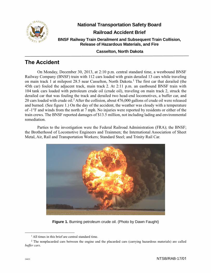
20 cars loaded with crude oil.2 After the collision, about 476,000 gallons of crude oil were released
and burned. (See figure 1.) On the day of the accident, the weather was cloudy with a temperature
of -1°F and winds from the north at 7 mph. No injuries were reported by residents or either of the
train crews. The BNSF reported damages of $13.5 million, not including lading and environmental
remediation.
Parties to the investigation were the Federal Railroad Administration (FRA); the BNSF;
the Brotherhood of Locomotive Engineers and Trainmen; the International Association of Sheet
Metal, Air, Rail and Transportation Workers; Standard Steel; and Trinity Rail Car.
Figure 1. Burning petroleum crude oil. (Photo by Dawn Faught)
1 All times in this brief are central standard time. 2 The nonplacarded cars between the engine and the placarded cars (carrying hazardous materials) are called
buffer cars.
2
Accident Narrative
The westbound BNSF train (grain train), G-RYLRGT9-26A, traveling on main track 1, had
two head-end locomotives and one rear-end distributed locomotive power unit (DPU) in addition
to the 112 cars that were loaded with grain.3 Four crewmembers were on board the train: an
engineer, a conductor, a road foreman of engines conducting a check ride with the grain train crew,
and a student engineer.4
At the accident site near Casselton, North Dakota, there were two main tracks, part of a
traffic control system, with each track signaled for train movements in both directions. The tracks
were parallel and oriented geographically in an east-west direction. The north track was designated
main track 1, and the south track was designated main track 2.
A signal maintainer, who was near the west switch of the Casselton crossover at
milepost 28.5, noticed that some of the switch heater covers were damaged and told the grain train
crew by radio.5 The damage to the covers, which were on the outside of the rails, suggested that
the cause of the damage could be equipment hanging from a rail car and dragging along the track.
During that conversation, the grain train experienced an emergency brake application when 13 cars
(the 43rd through the 55th) derailed, at milepost 28.5. Data from the grain train’s event and video
recorders showed that at 2:10 p.m. the grain train went into an emergency brake application.6 The
first car that derailed was the 45th car, which fouled the adjacent main track 2, pulling the 44th car
off the track. The 44th car caused one truck of the 43rd car to derail.
At the time, the eastbound BNSF train loaded with crude oil, U-FYNHAY4-05T (oil train),
with two head-end locomotives, a rear DPU, and one buffer car on either end of the 104 tank cars
loaded with crude oil, was leaving the Jamestown Subdivision and entering the KO Subdivision at
milepost 31.1, operating on main track 2 west of control point Casselton. The crew of the oil train
consisted of an engineer and a conductor.
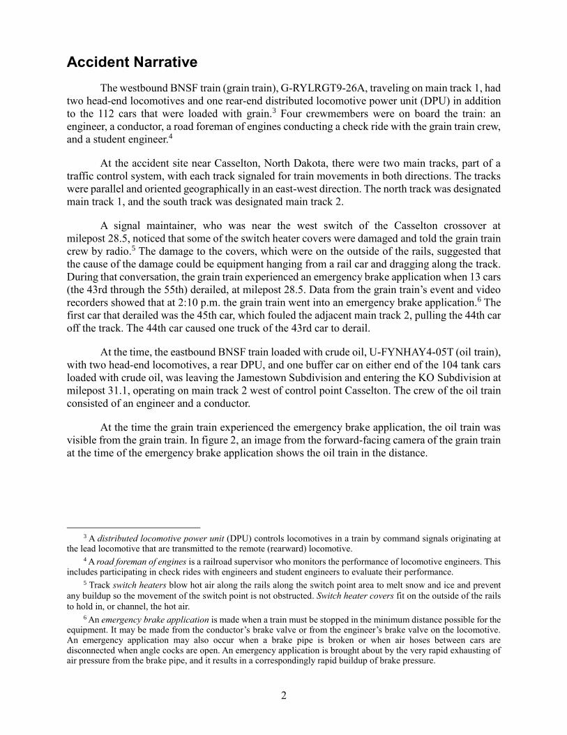
At the time the grain train experienced the emergency brake application, the oil train was
visible from the grain train. In figure 2, an image from the forward-facing camera of the grain train
at the time of the emergency brake application shows the oil train in the distance.
3 A distributed locomotive power unit (DPU) controls locomotives in a train by command signals originating at
the lead locomotive that are transmitted to the remote (rearward) locomotive. 4 A road foreman of engines is a railroad supervisor who monitors the performance of locomotive engineers. This
includes participating in check rides with engineers and student engineers to evaluate their performance. 5 Track switch heaters blow hot air along the rails along the switch point area to melt snow and ice and prevent
any buildup so the movement of the switch point is not obstructed. Switch heater covers fit on the outside of the rails
to hold in, or channel, the hot air. 6 An emergency brake application is made when a train must be stopped in the minimum distance possible for the
equipment. It may be made from the conductor’s brake valve or from the engineer’s brake valve on the locomotive. An emergency application may also occur when a brake pipe is broken or when air hoses between cars are disconnected when angle cocks are open. An emergency application is brought about by the very rapid exhausting of air pressure from the brake pipe, and it results in a correspondingly rapid buildup of brake pressure.
3
Figure 2. View from forward-facing video camera of grain train at the time the train went into emergency braking because the train had separated.
After the grain train’s emergency brake application, the crew began to implement the safety
protocols required after an emergency brake application: a crewmember immediately broadcast an
emergency announcement to other trains in the area, using radio channel 70, and as the train was
stopping the crew prepared to inspect the train to determine the reason the brake line air pressure
had been lost (as shown on gauges in the locomotive cab) that resulted in the emergency stop.7
The safety protocol also required the train crew to walk along the train to ascertain the cause of
the loss of pressure and to determine whether cars had derailed.
However, the oil train crew did not hear the emergency announcement from the grain train
because they were releasing track warrant authority to the train dispatcher on radio channel 39
assigned to the Jamestown Subdivision. This was in accordance with BNSF operating rules, which
state that a train must release a track warrant after it leaves the limits of the warrant. After the grain
7 (a) The radio channels discussed in this report are assigned by the Association of American Railroads (AAR).
AAR channel 70 is used for the KO Subdivision, and channel 39 is used for the Jamestown Subdivision. The grain train was operating on the KO Subdivision. (b) BNSF operating rules, the General Code of Operating Rules – Sixth Edition, and the BNSF’s Railway Air Brake and Train Handling Rules No. 5 require specific actions by train crew members when an emergency brake application occurs: Move the automatic brake valve handle to “Emergency” and wait until the train stops. After stopping, if operating conditions permit, place the automatic brake valve handle in “Release” to release the brakes, and help locate the air hose separation or other problem.
4
train crew made the emergency announcement, the road foreman of engines attempted to contact
the oil train crew by radio to alert them to the emergency brake application.
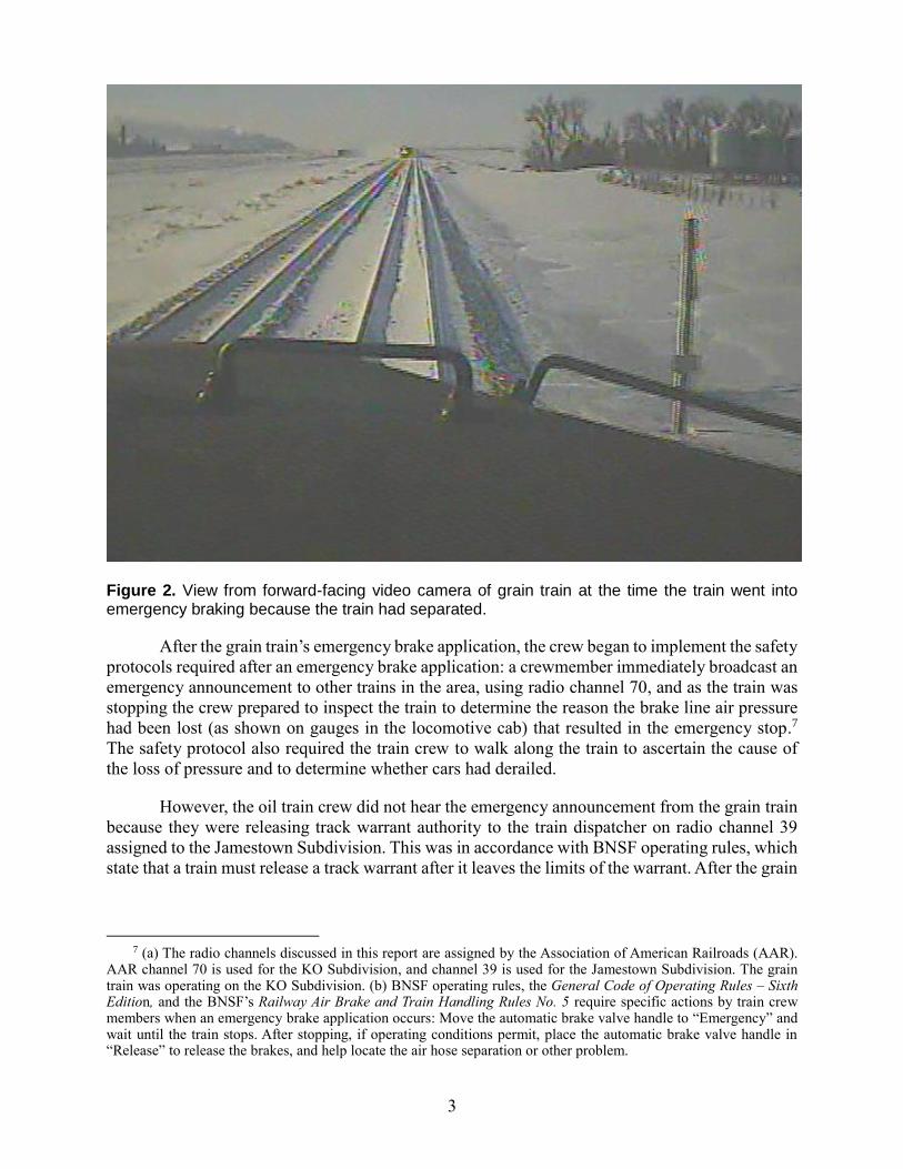
As the oil train proceeded on main track 2 toward the Casselton crossover, it passed the
head end of the grain train, which was still traveling about 17 mph and was about 245 feet away
from where it eventually stopped. About 33 seconds later, the oil train crew saw the derailed car
on the track ahead, and the engineer made an emergency brake application. (See figure 3.) The
lead locomotive of the oil train was traveling 42 mph when it struck the derailed grain car at
2:11 p.m., causing the oil train’s two locomotives, single buffer car, and the first 20 loaded tank
cars to derail to the south of the track.
Figure 3. View from forward-facing video camera of oil train before collision.
The front door of the lead locomotive of the oil train was damaged, preventing the crew
from using that door. The crew escaped through the rear door of the lead locomotive and went east
to the nearest highway-rail grade crossing, where they met emergency responders.
In total, about 476,000 gallons of crude oil were released from derailed tank cars that were
punctured, from those with damaged bottom valves and top fittings, and from those that ruptured
during the fire. The spilled crude oil created pools that caught fire. Other derailed tank cars
eventually ruptured as the pool fires weakened the tank steel and increased the internal pressure.
The resulting thermal tears released superheated crude oil vapor that immediately erupted into
violent fireballs above the tank cars. (See figure 1.)
5
Emergency Response
At 2:11 p.m. the local fire department received a 911 call reporting a train derailment west
of Casselton, North Dakota. A second call to the Red River Regional Dispatch Center at 2:12 p.m.
reported a train derailment and fire. Shortly thereafter, Cass County established a unified command
for the incident that included the Cass County Sheriff’s Department and the Casselton Fire
Department. At 4:14 p.m., the Cass County sheriff ordered a 3/4-mile isolation perimeter around
the accident site. The unified command estimated that about 1,400 people had voluntarily
evacuated. Emergency responders established a safe perimeter and allowed the tank cars to burn.
At 5:32 p.m., the tactical operations center, which was coordinating the emergency response,
verified that the voluntary evacuation had been expanded to include a western portion of the city.
After the grain train stopped, the crew walked to a nearby highway-rail grade crossing
where they were met by the assistant fire chief of the Casselton Fire Department. The train crew
then assisted the emergency responders by pulling the nonderailed west portion of the oil train cars
away from the burning derailed cars. The cars were moved about 1/4 mile west using the DPU at
the end of the train.
About 30 to 45 minutes after the grain train crew completed moving the first set of cars
away from the fire, the assistant fire chief of the Casselton Fire Department met the grain train
crew at the rear locomotive (the DPU) of the oil train and asked if additional tank cars closer to
the derailment area could be moved. The student engineer accompanied the assistant fire chief to
couple the train back together and make an additional separation between the tank cars near the
derailed burning tank cars. The student engineer borrowed fire-protective clothing, walked to a
location less than 10 cars away from the fire, and uncoupled the cars to the east. The engineer then
pulled about 20 tank cars 1/4 mile west away from the fire.
At 7:11 p.m., the voluntary evacuation order was expanded to encompass all of Casselton,
because the wind was coming from the west, and a weather system was forcing smoke and
combustion products to the ground. Near the end of the evacuation, the unified command estimated
that the number of evacuees had increased to about 1,560 residents. The next day at 3:00 p.m., the
unified command lifted the voluntary evacuation recommendation, and residents returned to their
homes.
Method of Operations
Train movements on the KO Subdivision are governed by signal indications of a traffic
control system. Train movements on the Jamestown Subdivision are governed by a track warrant
control/automatic block system. The Jamestown Subdivision train dispatcher grants track authority
by mandatory directive, which means authorities are dictated by the dispatcher and copied by the
train crew on standard track warrant forms. BNSF operating rules state that when a train exits track
warrant control territory, the crew must release its authority by communicating its location to the
train dispatcher.
The oil train crew made the required communication to the Jamestown Subdivision
dispatcher using radio channel 39. According to signal data, about 2:10 p.m. the oil train occupied
the track east of the controlled signal displaying a flashing yellow over red aspect at
6
control point 30 on main track 2.8 At this point, the oil train was about 1 1/2 miles from the point
of collision with the grain car.
Hazardous Materials
The oil train was a unit train with 104 tank cars containing petroleum crude oil that were
in positions 2 through 105.9 The train was designated a key train placarded with United Nations
identification number 1267, signifying petroleum crude oil, which is a hazard Class 3 flammable
liquid.10 The shipper classified the crude oil as Packing Group I, meaning that it poses the greatest
degree of danger during transportation.11 Commercial transport of petroleum crude oil is subject
to the requirements of the Hazardous Materials Regulations in Title 49 Code of Federal
Regulations (CFR) Parts 100–185.12
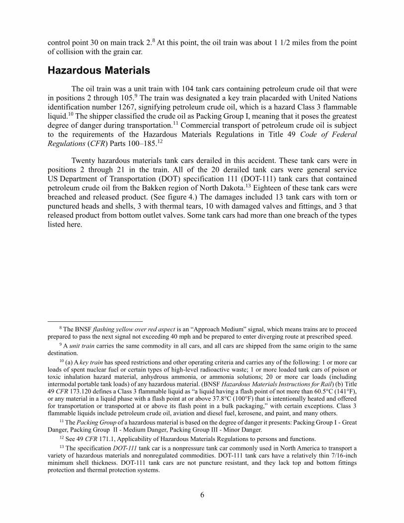
Twenty hazardous materials tank cars derailed in this accident. These tank cars were in
positions 2 through 21 in the train. All of the 20 derailed tank cars were general service
US Department of Transportation (DOT) specification 111 (DOT-111) tank cars that contained
petroleum crude oil from the Bakken region of North Dakota.13 Eighteen of these tank cars were
breached and released product. (See figure 4.) The damages included 13 tank cars with torn or
punctured heads and shells, 3 with thermal tears, 10 with damaged valves and fittings, and 3 that
released product from bottom outlet valves. Some tank cars had more than one breach of the types
listed here.
8 The BNSF flashing yellow over red aspect is an “Approach Medium” signal, which means trains are to proceed
prepared to pass the next signal not exceeding 40 mph and be prepared to enter diverging route at prescribed speed. 9 A unit train carries the same commodity in all cars, and all cars are shipped from the same origin to the same
destination. 10 (a) A key train has speed restrictions and other operating criteria and carries any of the following: 1 or more car
loads of spent nuclear fuel or certain types of high-level radioactive waste; 1 or more loaded tank cars of poison or toxic inhalation hazard material, anhydrous ammonia, or ammonia solutions; 20 or more car loads (including intermodal portable tank loads) of any hazardous material. (BNSF Hazardous Materials Instructions for Rail) (b) Title 49 CFR 173.120 defines a Class 3 flammable liquid as “a liquid having a flash point of not more than 60.5°C (141°F), or any material in a liquid phase with a flash point at or above 37.8°C (100°F) that is intentionally heated and offered for transportation or transported at or above its flash point in a bulk packaging,” with certain exceptions. Class 3 flammable liquids include petroleum crude oil, aviation and diesel fuel, kerosene, and paint, and many others.
11 The Packing Group of a hazardous material is based on the degree of danger it presents: Packing Group I - Great Danger, Packing Group II - Medium Danger, Packing Group III - Minor Danger.
12 See 49 CFR 171.1, Applicability of Hazardous Materials Regulations to persons and functions. 13 The specification DOT-111 tank car is a nonpressure tank car commonly used in North America to transport a
variety of hazardous materials and nonregulated commodities. DOT-111 tank cars have a relatively thin 7/16-inch minimum shell thickness. DOT-111 tank cars are not puncture resistant, and they lack top and bottom fittings protection and thermal protection systems.
7
Figure 4. Derailed tank car with large thermal tear.
Event Recorder Data
The grain train had three event recorders that were undamaged and provided data from the
two locomotives at the head end and the DPU. From the oil train, event recorder data from only
the DPU locomotive could be retrieved. The remaining two event recorders, in the lead
locomotives, were damaged by the severe thermal conditions, and fire destroyed the nonvolatile
memory.14
Investigators retrieved video recorder images from the forward-facing video recorders on
both trains. The video from the grain train was downloaded from the undamaged GE Lococam on
the lead locomotive. Video from the oil train had been transmitted wirelessly when the emergency
brake application was initiated; the on-board image recorder was destroyed in the postimpact fire.15
14 Nonvolatile memory is a type of solid state memory that does not require electric power to retain information. 15 When a BNSF train experiences an emergency brake application, its on-board video recorders automatically
send a burst of data, generally the 30 seconds before the emergency brake application. For additional information on the destroyed nonvolatile memory, see the Event and On-Board Image Recorders Factual Report in the NTSB docket by visiting NTSB Docket and searching for NTSB accident identification number DCA14MR004.
8
Tests and Research
Investigators found an axle assembly in the wreckage that was broken in half. On-scene
examination suggested that the axle had fractured at a void along the longitudinal center axis.16
The axle was sent to the National Transportation Safety Board (NTSB) materials laboratory for
further examination. The results of the examination are discussed later in this section.
The Casselton accident is one of several North American crude oil and ethanol train
derailments that have resulted in the release of large volumes of flammable liquids.17 These
accidents raise concern for the safety of people, property, and the environment and led the NTSB
to conduct a study to quantify the expected stopping distance of a train as a function of train mass,
train speed, track grade, train braking type, emergency or full service brake application, and the
use of locomotive brakes (released or applied, as applicable) or dynamic brakes.18 The study is in
the appendix of this report.
Broken Axle
The broken axle was an Association of American Railroads (AAR) Class K axle
manufactured for freight car service.19 The wheels mounted on the axle were stamped with a
manufacturing date of January 2010. The end of the broken axle was stamped with
“SSD 1102 7A1 E 0912 F,” indicating it was made by Standard Steel LLC (Standard Steel) in
November 2002. According to the AAR Manual of Standards and Recommended Practices,
(MSRP) Specification M-101, Appendix C, dated May 1, 1998, AAR serial number designations
contain a heat identification number that is stamped on the end of the axle.20 The term “heat” refers
to a specific pour of molten steel used to cast the axles, and heat numbers identify production runs
for quality control. The broken axle’s heat number was E0912.
The NTSB performed an ultrasonic inspection of the axle to characterize the dimensions
of the void. Figure 5 shows the two broken axle segments after testing, indicating the size and
location of the exposed, confirmed void at the fractured ends of both axle segments (shown in
blue). The figure also shows three other indications found by the inspection, which at the time
16 A void is a manufacturing defect in an otherwise solid material that can lead to premature failure of a component. 17 Other accidents include Lac Mégantic, Quebec, Canada (DCA13SR006); Cherry Valley, Illinois
(DCA09MR006); and Mount Carbon, West Virginia (DCA15FR005). For more details about these accidents, go to NTSB Docket and search for the NTSB accident identification numbers listed.
18 National Transportation Safety Board, Train Braking Simulation Study (Washington, DC: National Transportation Safety Board, 2015). NTSB Train Braking Study. Technical representatives from the BNSF, Trinity Rail Car, Standard Steel, the Brotherhood of Locomotive Engineers and Trainmen, the Federal Railroad Administration (FRA), and Sharma & Associates Inc. reviewed draft versions of this study and provided valuable feedback regarding railroad industry operations. Their technical comments were used to revise the study to account for physical constraints (based on locomotive tractive effort and dynamic braking limitations) as well as for operational considerations.
19 The AAR is the trade association that sets railroad policy, conducts research, sets standards, and advances
technology for its member railroads. The AAR is responsible for the interchange rules and the billing for freight car
repairs and repair databases. 20 Association of American Railroads, Manual of Standards and Recommended Practices (Washington, DC: AAR,
1998).

9
were potential voids, all of which were located closer to the wheel seat ends of the axle segments
(shown in green).
Figure 5. Axle segments after nondestructive ultrasonic testing.
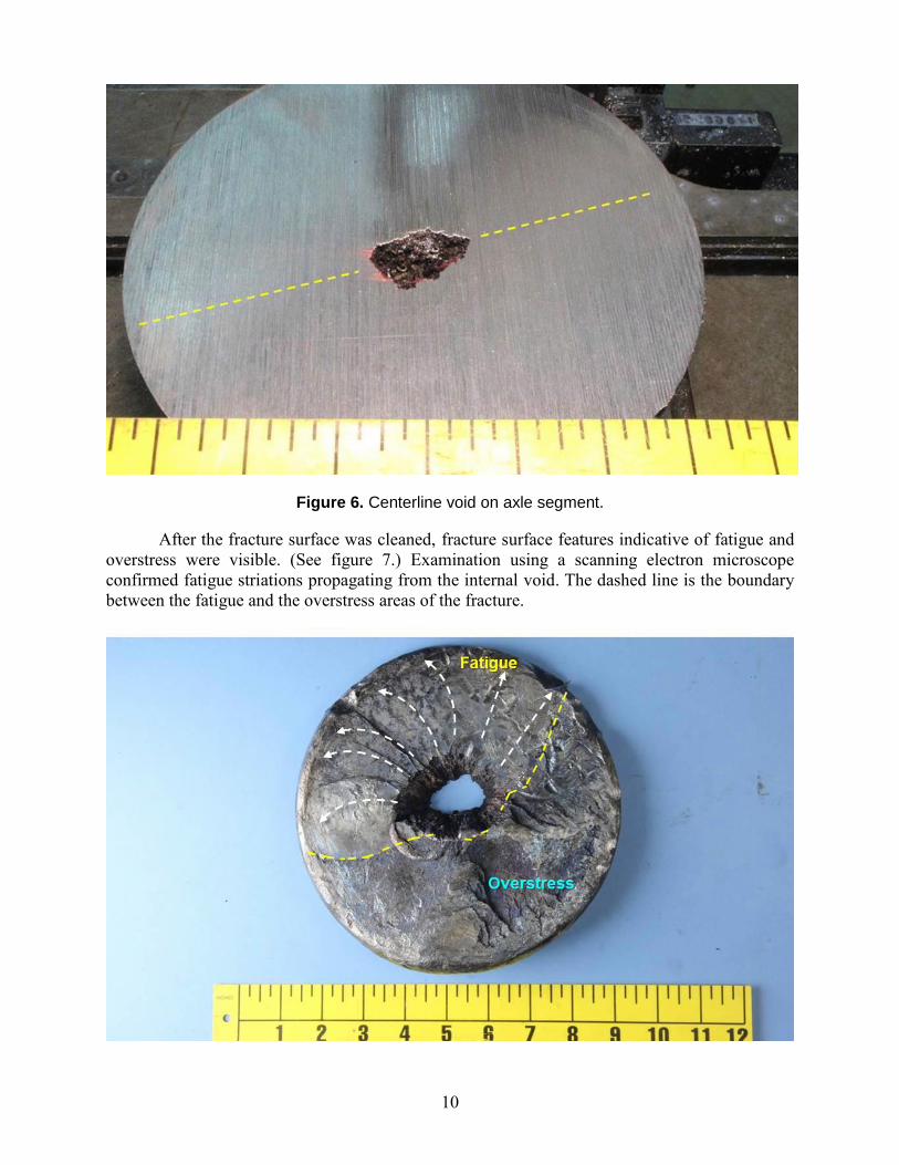
The internal centerline void on the longer axle segment, after removal of the fracture
surface (about 1 inch deep), is shown in figure 6. On the cut plane, the void measured 1.25 inches
by 0.75 inches. 0.
10
Figure 6. Centerline void on axle segment.
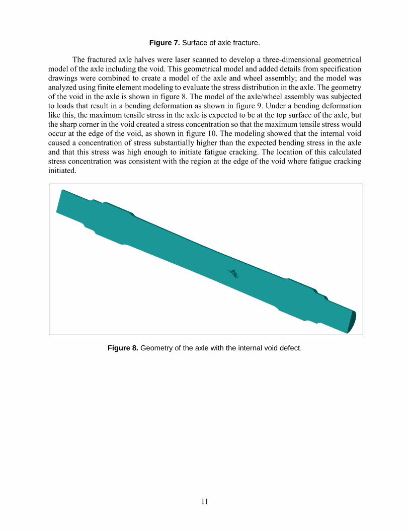
After the fracture surface was cleaned, fracture surface features indicative of fatigue and
overstress were visible. (See figure 7.) Examination using a scanning electron microscope
confirmed fatigue striations propagating from the internal void. The dashed line is the boundary
between the fatigue and the overstress areas of the fracture.
11
Figure 7. Surface of axle fracture.
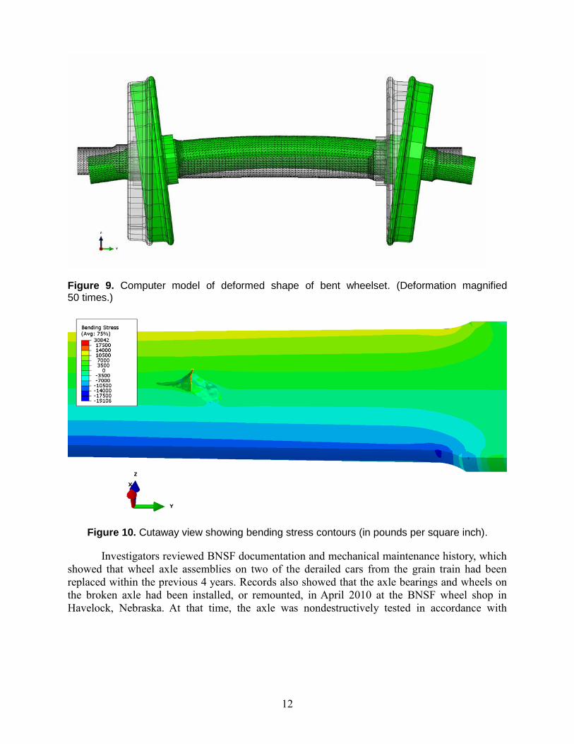
The fractured axle halves were laser scanned to develop a three-dimensional geometrical
model of the axle including the void. This geometrical model and added details from specification
drawings were combined to create a model of the axle and wheel assembly; and the model was
analyzed using finite element modeling to evaluate the stress distribution in the axle. The geometry
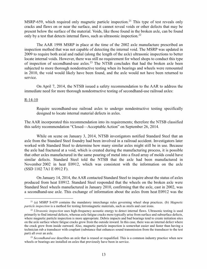
of the void in the axle is shown in figure 8. The model of the axle/wheel assembly was subjected
to loads that result in a bending deformation as shown in figure 9. Under a bending deformation
like this, the maximum tensile stress in the axle is expected to be at the top surface of the axle, but
the sharp corner in the void created a stress concentration so that the maximum tensile stress would
occur at the edge of the void, as shown in figure 10. The modeling showed that the internal void
caused a concentration of stress substantially higher than the expected bending stress in the axle
and that this stress was high enough to initiate fatigue cracking. The location of this calculated
stress concentration was consistent with the region at the edge of the void where fatigue cracking
initiated.
Figure 8. Geometry of the axle with the internal void defect.
12
Figure 9. Computer model of deformed shape of bent wheelset. (Deformation magnified 50 times.)
Figure 10. Cutaway view showing bending stress contours (in pounds per square inch).
Investigators reviewed BNSF documentation and mechanical maintenance history, which
showed that wheel axle assemblies on two of the derailed cars from the grain train had been
replaced within the previous 4 years. Records also showed that the axle bearings and wheels on
the broken axle had been installed, or remounted, in April 2010 at the BNSF wheel shop in
Havelock, Nebraska. At that time, the axle was nondestructively tested in accordance with
13
MSRP-659, which required only magnetic particle inspection.21 This type of test reveals only
cracks and flaws on or near the surface, and it cannot reveal voids or other defects that may be
present below the surface of the material. Voids, like those found in the broken axle, can be found
only by a test that detects internal flaws, such as ultrasonic inspection.22
The AAR 1998 MSRP in place at the time of the 2002 axle manufacture prescribed an
inspection method that was not capable of detecting the internal void. The MSRP was updated in
2009 to require both axial and radial (along the length of the axle) ultrasonic inspections to better
locate internal voids. However, there was still no requirement for wheel shops to conduct this type
of inspection of secondhand-use axles.23 The NTSB concludes that had the broken axle been
subjected to more thorough nondestructive testing when its bearings and wheels were remounted
in 2010, the void would likely have been found, and the axle would not have been returned to
service.
On April 7, 2014, the NTSB issued a safety recommendation to the AAR to address the
immediate need for more thorough nondestructive testing of secondhand-use railroad axles:
R-14-10
Require secondhand-use railroad axles to undergo nondestructive testing specifically
designed to locate internal material defects in axles.
The AAR incorporated this recommendation into its requirements; therefore the NTSB classified
this safety recommendation “Closed—Acceptable Action” on September 26, 2014.
While on scene on January 3, 2014, NTSB investigators notified Standard Steel that an
axle from the Standard Steel foundry had been involved in a railroad accident. Investigators later
worked with Standard Steel to determine how many similar axles might still be in use. Because
the axle had fractured at a void, which is created during the manufacturing process, it is possible
that other axles manufactured in the same pouring of metal into a fixed array of molds could have
similar defects. Standard Steel told the NTSB that the axle had been manufactured in
November 2002 in heat E0912, which was consistent with the information on the axle
(SSD 1102 7A1 E 0912 F).
On January 14, 2014, the AAR contacted Standard Steel to inquire about the status of axles
produced from heat E0912. Standard Steel responded that the wheels on the broken axle were
Standard Steel wheels manufactured in January 2010, confirming that the axle, cast in 2002, was
a secondhand-use axle. This exchange of information about the axles from heat E0912 was the
21 (a) MSRP S-659 contains the mandatory interchange rules governing wheel shop practices. (b) Magnetic
particle inspection is a method for testing ferromagnetic materials, such as steels and cast irons. 22 Ultrasonic inspection uses high-frequency acoustic energy to detect internal flaws. Ultrasonic testing is used
primarily to find internal defects, whereas axle fatigue cracks more typically arise from surface and subsurface defects, where magnetic particle inspection is more appropriate. Debris impacts and bad bearings tend to create initiation sites on the axle surface where fatigue cracks grow from the outside inward. In this case, there was an internal defect where the crack grew from inside outward. Also, magnetic particle inspection is somewhat easier and faster than having a technician rub a transducer with couplant (substance that enhances sound transmission from the transducer to the test part) all over an axle.
23 Secondhand-use describes an axle that is reused or requalified. This is a common industry practice when new wheels or bearings are installed on axles that previously have been in service.
14
beginning of an ongoing collaborative effort by the AAR and Standard Steel that continued through
May 2015.
On January 15, 2014, Standard Steel gave the AAR a list of the 48 axles in heat E0912 and
where each axle had originally been shipped. Standard Steel also described to the AAR how to
identify the axles. On January 17, 2014, the AAR requested a list of axle serial numbers from heat
E0912 so it could search its Comprehensive Equipment Performance Monitoring (CEPM) system
for axles that had been through a wheel shop and remounted. On January 21, 2014, the AAR
informed Standard Steel that no serial numbers from heat E0912 were in its CEPM system. On
January 23, 2014, the AAR issued Maintenance Advisory MA-144 to railroads and wheel shops
asking them to inspect axle serial numbers to identify and remove from service the remaining axles
in heat E0912.24
Beginning on February 14, 2014, Standard Steel contacted car manufacturers in an ongoing
and sustained effort requesting a list of railcars on which axles from heat E0912 may have been
installed. From the responses, Standard Steel compiled a list of 1,691 cars that might have been
equipped with one or more of the axles and sent the information to the car manufacturers.
On March 4, 2014, the AAR’s Wheels, Axles, Bearings, and Lubrication Committee
discussed performing radial ultrasonic testing on secondhand axles and the CEPM reporting of
axle serial numbers when remounting secondhand axles. On March 14, 2014, the AAR responded
to a request from Standard Steel with the information that according to its car repair billing records
for wheel set removals, 233 of the 1,691 cars that might have been built with axles from heat E0912
had had all four axles replaced since they were built, and therefore were no longer suspect. On
March 17, 2014, Standard Steel requested that the AAR provide a list of the owners of the
remaining 1,458 cars so that owners could check billing records on those cars. The AAR provided
the list the next day.
On March 24, 2014, NTSB investigators visited Standard Steel’s facility to further discuss
recent efforts by Standard Steel and the AAR to identify and locate rail cars with axles from heat
E0912. All agreed to continue the collaborative effort in the hope of finding additional axles. This
effort identified a total of 531 cars that might have axles from heat E0912 and 1,160 cars that did
not (including the 233 noted above). On June 16, 2014, the AAR issued a supplement to MA-144
(Supplement 1), listing the 531 cars that might have axles from heat E0912 and needed to be
field tested.25
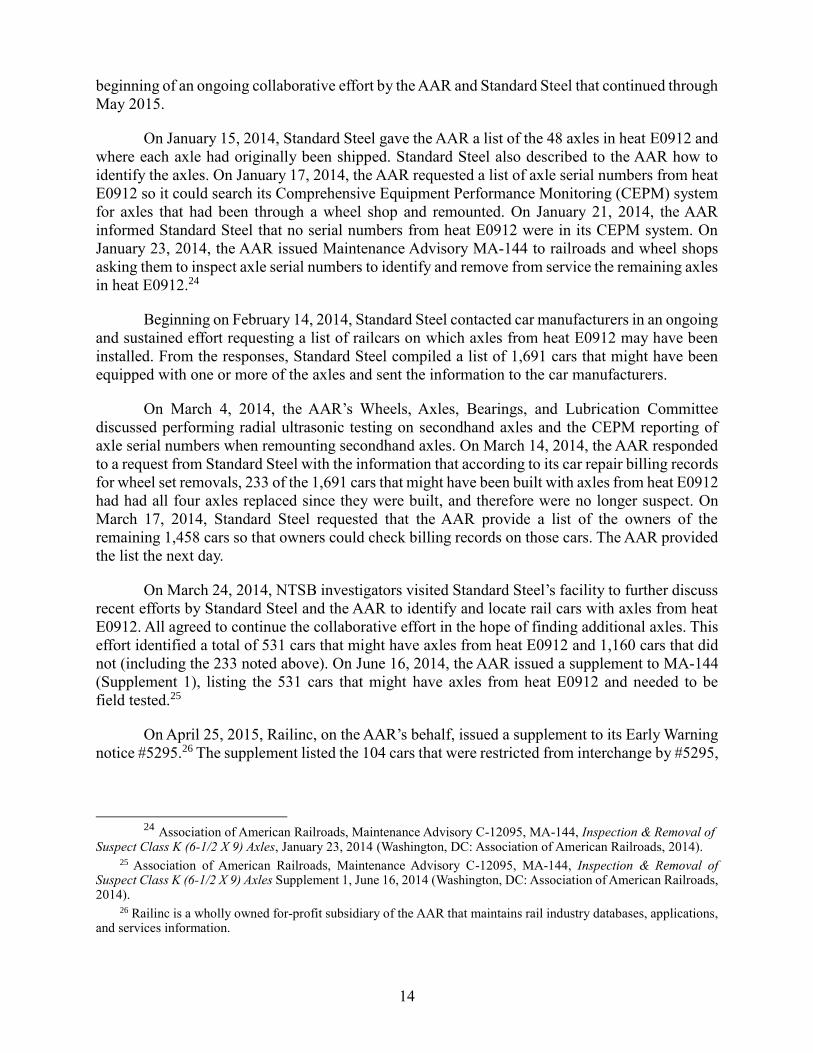
On April 25, 2015, Railinc, on the AAR’s behalf, issued a supplement to its Early Warning
notice #5295.26 The supplement listed the 104 cars that were restricted from interchange by #5295,
24 Association of American Railroads, Maintenance Advisory C-12095, MA-144, Inspection & Removal of
Suspect Class K (6-1/2 X 9) Axles, January 23, 2014 (Washington, DC: Association of American Railroads, 2014). 25 Association of American Railroads, Maintenance Advisory C-12095, MA-144, Inspection & Removal of
Suspect Class K (6-1/2 X 9) Axles Supplement 1, June 16, 2014 (Washington, DC: Association of American Railroads, 2014).
26 Railinc is a wholly owned for-profit subsidiary of the AAR that maintains rail industry databases, applications, and services information.
15
which is still in effect.27 However, only 2 of the 104 cars have not been physically located; they
are not easily accessible because they are in deep storage and not likely to enter service or
interchange with other railroads.
By the end of December 2016, 10 additional axles had been identified, primarily through
AAR-approved wheel and axle shop inspections resulting from the MA-144 advisory. The axles
were sent to Standard Steel’s facility for examination and ultrasonic testing. Five of the axles tested
had no indications of internal voids. The other five axles did have indications, but the axles met
the acceptance criteria in AAR M-101.28
BNSF Postaccident Actions
In February 2014, the BNSF began radial ultrasonic testing of all secondhand axles at its
Havelock wheel shop. This action was taken before Safety Recommendation R-14-10 was issued
to the AAR on April 7, 2014.
In March 2014, the AAR, along with its member Class I railroads, including the BNSF,
entered into a voluntary agreement with the US Secretary of Transportation that included
commitments the railroads would make. Those commitments include the following, which had
been stated in a February 21, 2014, letter from the Secretary of Transportation to the AAR
President and Chief Executive Officer:29
Speed reduction to 40 mph for hazardous materials carried in DOT-111 tank
cars traveling through high-threat urban areas (effective July 1, 2014)
Increased trackside safety technology on crude oil routes by installing
additional hot bearing detectors spaced at least 40 miles apart (effective July 1,
2014)30
Increased the frequency of rail flaw inspections (effective March 25, 2014)
Implemented the following additional emergency response actions:
Allocated $5 million for crude oil-specific hazardous materials training
Developed an inventory of emergency response resources along crude oil
train routes
27 Restricted from interchange means that the cars on Early Warning notice #5295 cannot be moved from one
railroad to another, which uses an interchange track between railroad properties. 28 Association of American Railroads, Manual of Standards and Recommended Practices, Section G, Wheels and
Axles, M-101, 16.7, Inspection (Washington, DC: Association of American Railroads, 2009), 8. 29 Letter from the US Secretary of Transportation to the AAR and its railroad subscribers, February 21, 2014:
02/21/2014 Letter to AAR. 30 A hot bearing detector, also called a hot box, is a heat-sensitive device that measures the relative temperature
of passing journal bearings.

16
Identified locations for staging emergency response equipment
Identified contacts for community notification
To implement these voluntary agreements, the BNSF developed geographic response plans
for certain routes and increased geometry car operations on key train routes from once a year to
twice a year.
In July 2014, the BNSF entered into an agreement with the Brotherhood of Railway
Carmen that included the following:
Increasing the number of qualified mechanical inspectors
Inspecting crude oil unit trains at origination31
Expanding the BNSF’s employment of about 17 mobile [car] inspectors who inspect,
repair, and maintain equipment at originating crude oil terminals in the Bakken region
to include crude oil unit train origination points in Wyoming and Colorado
By the end of 2014, the BNSF had trained more than 8,500 local emergency responders
and sponsored the training of 713 firefighters at the Transportation Technology Center, Inc.
(TTCI), in Pueblo, Colorado. The BNSF sponsored 500 firefighters to attend TTCI training in
2015.
Effective March 25, 2015, the BNSF took voluntary action to reduce or restrict to 35 mph
the authorized operational speed for all key trains through population centers of 100,000 or more
people. The BNSF conducts remote audits of event recorder downloads to ensure compliance with
these new operational changes.
The BNSF has increased the use of trackside safety technology by adding hot box detectors
spaced 10 miles apart near critical waterways. Also, the company has improved the handling of
indications from wheel impact load detectors (WILD), which monitor the health of in-service
railcar wheels.32 The improved procedures treat a level II readout of 120−140 kips the same way
a more serious level I indication is treated, and they require that the car be set out of the train
immediately.33 Additionally, the BNSF has increased rail detection frequency along critical
waterways to 2 1/2 times the frequency required by the FRA.
31 Title 49 CFR 174.9 requires a hazardous materials acceptance inspection. 32 (a) A wheel impact load detector (WILD) measures impact loads, indicates wheel tread defects, and signifies
damage protection. (b) A WILD indication is a measurement based on the reading from WILD equipment. A level 1 indication refers to those cars (wheels) that measure more than 140 kips, indicating that there is something seriously wrong with the impact level that the wheel is making. The BNSF requires the train to be stopped and the car and wheels to be inspected, and depending on the inspection results the train is given a slow order or the car is set out of the train. A level 2 indication is less serious than a level 1, and it refers to those cars that measure greater than or equal to 120 kips but less than 140 kips.
33 A kip is a unit of force equal to 1,000 pounds.
17
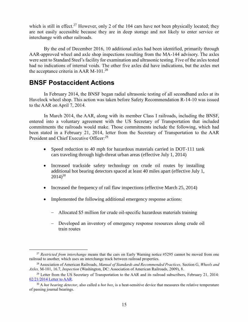
The BNSF also has taken the following actions on equipment health:
All wheels with WILD indications greater than 90 kips on key trains will be repaired
at the next available car repair location.
New composite alarm/threshold: A wheel on a key train with (1) WILD indications
equal to 70 kips and (2) one warm bearing outlier (K value greater than 2.5) will be
repaired at next available car repair location.34
Hot journal bearings, or “hot wheels” (HW): A key train meeting “hot wheels 1”
(HW1) (stop and inspect), HW2 (running air brake release), or HW3 (bad order to
destination) criteria will be monitored in real time, and the appropriate action will be
taken based on hot-wheel defect criteria.
Wheel quality: Defect criteria for car inspection based on more restrictive AAR
condemnable thresholds for thin rims, thin flange, and shelled tread.
Installation of 5 additional cracked-wheel detectors, for a total of 10, on key routes.
Research on vertical split rims (wheels): Destructive testing for 90 kips and greater
wheels off BNSF key trains to understand correlation between kip level and
propagation of subsurface horizontal wheel cracks.
TTCI tank car/track dynamics research: Incremental funding for TTCI to model the
interaction between loaded tank cars and certain track irregularities that lead to high
wheel/rail forces and derailments.
Before the Casselton accident, BNSF policy was that when a track occupancy indication
was left in two consecutive signal blocks behind a key train, that train was required to stop and be
inspected before any further movement. A track occupancy indication is a display on a train
dispatcher’s screen that shows that a train is in a specific signal block. When the train leaves the
signal block, the display should indicate that the train is in the next signal block and no longer in
the previous block. Thus, in the case that a dispatcher’s screen display indicates that a key train is
occupying two consecutive signal blocks, the dispatcher knows that a train is not in the first block
and another condition is causing the track occupancy indication. Because the track occupancy
indication was not displayed before the train entered the signal block, the most likely reason for
the indication is that the passage of the train caused a broken rail or other track condition that could
adversely affect the safe passage of the next train. Because the track condition could have been
caused by a defect in the train, such as a broken wheel, the train needs to be stopped and inspected
to find out what caused the problem. After this accident, the BNSF changed this procedure to
require a key train to be stopped and inspected for any defects after one track-occupancy indication
is left behind the train in a signal block.
34 K value is a normalized temperature value of the bearing relative to the bearings on the same side of the train
in which it is traveling. The value “k” is calculated by dividing the range between actual bearing temperature and the median bearing temperature for a group of data by the interquartile range for the same group of data.
18
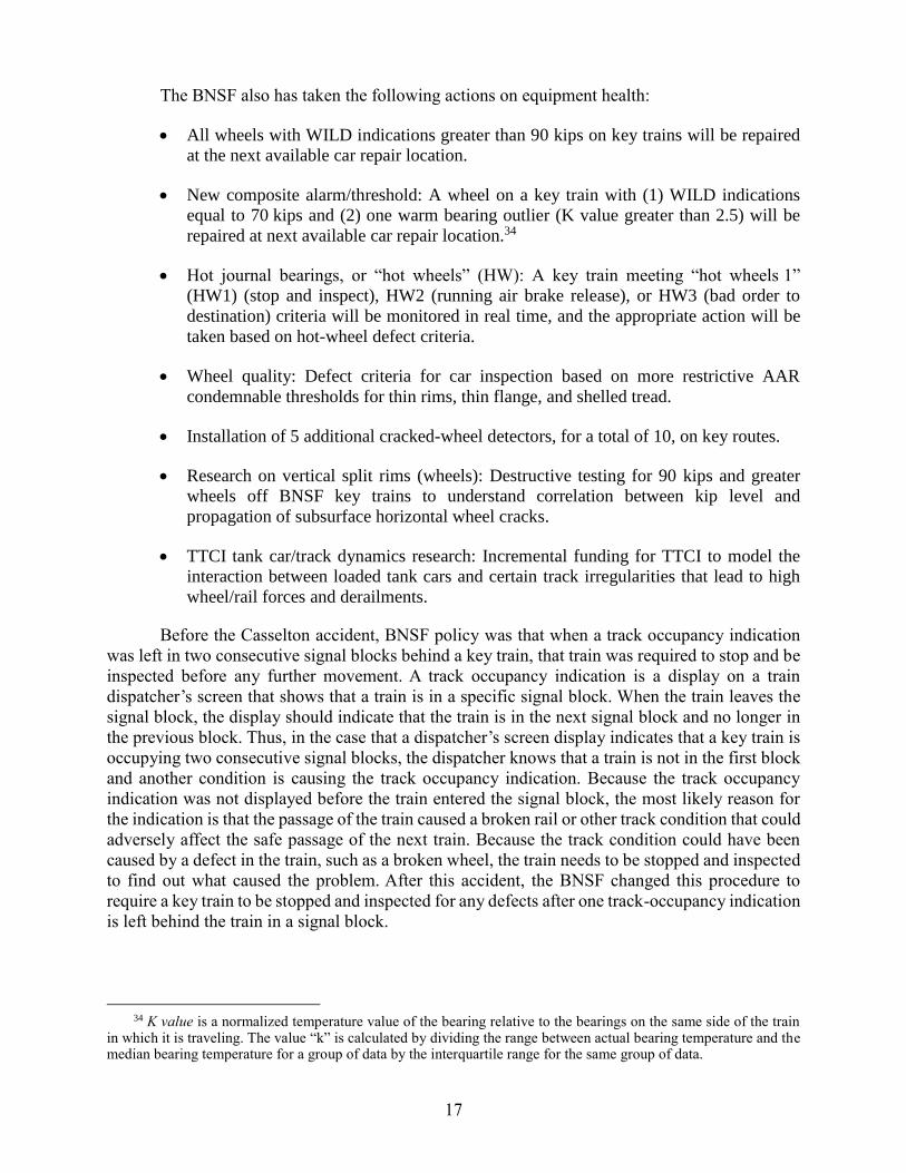
Pipeline and Hazardous Materials Safety Administration and Federal Railroad Administration Actions
The Pipeline and Hazardous Materials Safety Administration (PHMSA), in coordination
with the FRA, published a final rule, HM-251, Hazardous Materials: Enhanced Tank Car
Standards and Operational Controls for High-Hazard Flammable Trains, Federal Register 80,
no. 89 (May 8, 2015): 26644, adopting safety improvements in tank car design standards,
operational requirements, and notification requirements for tank cars used in trains defined as high-
hazard flammable trains (HHFT).35 The rule also includes new requirements for a sampling and
classification program for unrefined petroleum-based products. With respect to tank car and train
requirements, the rule specifically provides for the following:
Enhanced standards for new tank cars, which could include such tank car enhancements
as thicker shell material, full-height head shields, jackets, thermal protection, and
fittings protection
Existing tank cars phased out or retrofitted to an equivalent level of safety
Rail route safety and security risk assessment and alternate route analysis
Reduced operating speeds
Enhanced braking
Fixing America’s Surface Transportation Act
The President signed the Fixing America’s Surface Transportation Act (FAST Act),
Pub. L. 114-94, on December 4, 2015. Division A, Title VII, Subtitle C of the FAST Act affects
the implementation of PHMSA rule HM-251.36
The PHMSA final rule required that by January 1, 2021, each railroad carrier that operates
high-hazard flammable unit trains composed of at least one tank car loaded with a Packing
Group Me material, at a speed exceeding 30 mph, must meet the electronically controlled
pneumatic (ECP) braking capability requirements.
Section 7311 of the FAST Act requires the Comptroller General of the United States to
conduct an independent study and testing of ECP brake systems. This study evaluated ECP brake
systems, pilot program data, and DOT research and analysis on the costs, benefits, and effects of
ECP brake systems.37
35 High-hazard flammable train (HHFT) means a single train transporting 20 or more loaded tank cars of a Class 3
flammable liquid in a continuous block, or a single train carrying 35 or more loaded tank cars of a Class 3 flammable liquid throughout the train consist.
36 FAST Act. Accessed October 6, 2016. 37 Government Accountability Office, Train Braking: DOT’s Rulemaking on Electronically Controlled Pneumatic
Brakes Could Benefit from Additional Data and Transparency, GAO-17-122, (Washington, DC: US Government Accountability Office, 2016). GAO ECP Braking Report.
19
Sections 7301–7310 of the Act contain further mandates to enhance tank car safety for all
flammable liquid commodities regardless of train composition and to provide for safer and more
efficient emergency responses to accidents involving trains transporting hazardous materials.
Protecting Train Crews from Hazardous Materials
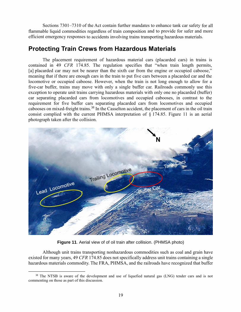
The placement requirement of hazardous material cars (placarded cars) in trains is
contained in 49 CFR 174.85. The regulation specifies that “when train length permits,
[a] placarded car may not be nearer than the sixth car from the engine or occupied caboose,”
meaning that if there are enough cars in the train to put five cars between a placarded car and the
locomotive or occupied caboose. However, when the train is not long enough to allow for a
five-car buffer, trains may move with only a single buffer car. Railroads commonly use this
exception to operate unit trains carrying hazardous materials with only one no placarded (buffer)
car separating placarded cars from locomotives and occupied cabooses, in contrast to the
requirement for five buffer cars separating placarded cars from locomotives and occupied
cabooses on mixed-freight trains.38 In the Casselton accident, the placement of cars in the oil train
consist complied with the current PHMSA interpretation of § 174.85. Figure 11 is an aerial
photograph taken after the collision.
Figure 11. Aerial view of of oil train after collision. (PHMSA photo)
Although unit trains transporting nonhazardous commodities such as coal and grain have
existed for many years, 49 CFR 174.85 does not specifically address unit trains containing a single
hazardous materials commodity. The FRA, PHMSA, and the railroads have recognized that buffer
38 The NTSB is aware of the development and use of liquefied natural gas (LNG) tender cars and is not
commenting on those as part of this discussion.
20
cars should be required on unit trains transporting hazardous materials to comply with the intent
of 49 CFR 174.85. Since a hazardous materials unit train is composed of cars loaded with the same
hazardous commodity, additional nonplacarded cars must be added to the train to provide a buffer
between occupied railcars and locomotives and the hazardous materials. The FRA, PHMSA, and
the railroads have interpreted the regulation to allow use of a single buffer car between the
locomotives and the first placarded car, and those trains may travel across the country with only
one buffer car required.39 Conversely, a train of mixed freight cars with one hazardous materials
car must have a five-car buffer between that car and the occupied locomotives unless the train is
too short and does not have enough cars to allow for a five-car buffer.
Previous NTSB Actions
The practice of using a single buffer car in unit trains transporting hazardous materials has
been a concern to the NTSB since the October 20, 2006, derailment of a Norfolk Southern Railway
Company train transporting ethanol in New Brighton, Pennsylvania. The accident raised questions
about the number and placement of buffer cars on trains transporting hazardous materials. The
New Brighton accident train was a unit train consisting of 3 locomotives pulling 3 empty freight
cars (buffer cars) followed by 83 tank cars loaded with denatured ethanol, a flammable liquid.
Twenty-three of the tank cars, cars 23 through 45 from the head end of the train, derailed. Because
the first car to derail was the 23rd car from the head end of the train, the train crew was not
endangered by the ethanol release, and therefore the placement of the buffer cars relative to the
ethanol tank cars in the accident train was not a factor in the crew’s protection in the accident. In
contrast, at Casselton, there was only one buffer car between the head-end locomotives and the
first tank car that derailed and burned. As a result of the New Brighton investigation, the NTSB
issued Safety Recommendations R-08-12 to the FRA and R-08-13 to PHMSA:
R-08-12
Assist the Pipeline and Hazardous Materials Safety Administration in its evaluation of the risks
posed to train crews by unit trains transporting hazardous materials, determination of the optimum
separation requirements between occupied locomotives and hazardous materials cars, and any
resulting revision of 49 Code of Federal Regulations 174.85.
R-08-13
With the assistance of the Federal Railroad Administration, evaluate the risks posed to train crews
by unit trains transporting hazardous materials, determine the optimum separation requirements
between occupied locomotives and hazardous materials cars, and revise 49 Code of Federal
Regulations 174.85 accordingly.
Both of these safety recommendations are currently classified “Open—Acceptable Response.”
39 Director of the PHMSA Office of Hazardous Materials Standards, March 29, 2007, letter, reference number
06-0278, to the NTSB Investigator-In-Charge of the October 20, 2006, derailment of a Norfolk Southern Railway Company train transporting ethanol in New Brighton, Pennsylvania. See National Transportation Safety Board, Derailment of Norfolk Southern Railway Freight Train 68QB119 with Release of Hazardous Materials and Fire, New Brighton, Pennsylvania, October 20, 2006, RAR-08/02 (Washington, DC: National Transportation Safety Board, 2008).
21
The FRA stated in its latest response to Safety Recommendation R-08-12 on
May 23, 2014, that it has reviewed 49 CFR Part 174, Carriage by Rail, which applies to rail
carriers that accept and transport hazardous materials by rail, and identified regulations that may
be outmoded, ineffective, insufficient, or excessively burdensome. Among those regulations
identified as potentially ineffective is the requirement for a single buffer car in a train where
train length does not permit additional buffer cars, such as a unit train. The FRA stated that it and
PHMSA were deliberating the best path forward to modify, streamline, expand, or repeal
regulations in 49 CFR Part 174, including the option of a rulemaking action to address
Safety Recommendation R-08-12. PHMSA provided a similar response to
Safety Recommendation R-08-13 on July 16, 2013.
On November 5, 2015, the Hazardous Materials Issues Working Group of the FRA
Railroad Safety Advisory Committee agreed upon Task No. 15-04, in participation with PHMSA,
to consider revisions to the Hazardous Materials Regulations, 49 CFR Parts 100–185, to enhance
rail safety. Among the Working Group proposals are the train placement and buffer car
requirements of 49 CFR 174.85 to provide unit trains with increased separation distance between
placarded tank cars and occupied locomotives. The FRA and PHMSA have planned to incorporate
draft rule revisions for Part 174 into an upcoming Notice of Proposed Rulemaking.
Eight years have passed with no action on Safety Recommendations R-08-12 and R-08-13
from the New Brighton accident investigation. Therefore the NTSB reclassifies Safety
Recommendations R-08-12 and -13 from “Open—Acceptable Response” to
“Closed―Unacceptable Action.”
Casselton Oil Train Crew Safety
Following the collision, the crew of the oil train narrowly escaped the area before the
locomotives were destroyed by the eruption of a postaccident fire and energetic fireballs.
During an interview with NTSB investigators the oil train conductor stated the following:
[I] was exiting the cab … and started to get away from all the fire. … The heat was
intense. … I was in knee-deep snow. I couldn’t get away as quickly as I would like
to. … It was about a minute later the locomotive that we were traveling in was
engulfed in flames. I suppose we were about 200 yards [away]. I believe that that’s
when one of the tankers exploded.40
NTSB investigators asked the conductor how long it took for the locomotive to be engulfed in
flames, and he said the following:
[It] seems like a minute to me, a couple minutes. … I turned around to make sure
my engineer was behind me, and that’s when I noticed that the locomotive was
being engulfed in flames.41
40 Conductor of oil train, interview by NTSB investigator, January 2, 2014. 41 Conductor interview, January 2, 2014.

22
He also stated that the first explosion occurred about 5 minutes after the derailment. He added
that an explosion occurred about every 10 minutes.42
The oil train engineer stated that after the collision, they saw “that there [was] fire, … a
lot of fire.”43 The engineer expressed concern that they had to exit the locomotive through the
back door because, “that’s the last place you wanted to go because [the] ground was on fire, the
engine was on fire.”44 As previously stated, egress from the locomotive door exiting toward the
front of the locomotive was not an option due to damage to the door.
Freight train crews may survive collisions and derailments only to be injured or killed by
hazardous materials released in the accident. A crew involved in a locomotive collision may
experience injuries that would limit the ability to rapidly exit the locomotive and thereby increase
the risk of injury from hazardous material release or fire.
Postaccident examination of the derailed tank cars in this accident found that hazardous
materials tank cars in positions 2 through 5 were breached and exhibited severe thermal damage.
The proximity of the locomotives to the hazardous materials tank cars placed the oil train
crew in peril following release of the crude oil that ignited and engulfed the locomotives in the
postaccident fire within a minute or two. The NTSB concludes that had additional buffer cars,
instead of flammable hazardous material tank cars, been placed in positions 2 through 5 of the
train, the danger to the train crew would have been significantly reduced and would have allowed
for more time for a safe egress from the locomotive. The NTSB further concludes that a one-car
buffer between the locomotives and the hazardous materials exposes the train crew to unnecessary
risk in accidents where cars are derailed closer to the head end of the train.
In a July 29, 2009, letter to the FRA about Safety Recommendation R-08-12, the NTSB
clarified that it recognized that the five-car buffer standard was not based upon any rigorous
engineering safety analysis, but since the 1920s it has become accepted by regulators and railroads.
Although the five-car buffer standard is considered to have been validated over many years, the
one-car buffer exception for hazardous materials unit trains does not have as lengthy a historical
record and also may not be sufficiently justified by historical or other data. The NTSB therefore
concludes that without safety justification of the one-car buffer exception, the current regulation
for the separation of hazardous materials from occupied locomotives and its interpretation by the
FRA, PHMSA, and the railroads create different levels of safety for crew protection from
hazardous materials on unit trains and general freight trains.
Unit trains that carry hazardous materials present a special risk because of their high
concentration of hazardous materials. Additional separation would provide greater protection to
train crews in the event of an accident. The NTSB concludes that the number and placement of
buffer cars should minimize the risk to the crew in occupied equipment. Therefore, the NTSB
recommends that PHMSA evaluate the risks posed to train crews by hazardous
materials transported by rail, determine the adequate separation distance between hazardous
materials cars and locomotives and occupied equipment that ensures the protection of train crews
during both normal operations and accident conditions, and collaborate with the FRA to revise
42 Conductor interview, January 2, 2014. 43 Engineer of oil train, interview by NTSB investigator, January 1, 2014. 44 Engineer interview, January 2, 2014.
23
49 CFR 174.85 to reflect those findings. The NTSB also recommends that the FRA evaluate the
risks posed to train crews by hazardous materials transported by rail, determine the adequate
separation distance between hazardous materials cars and locomotives and occupied equipment
that ensures the protection of train crews during both normal operations and accident conditions,
and collaborate with PHMSA to revise 49 CFR 174.85 to reflect those findings. These new safety
recommendations supersede Safety Recommendations R-08-13 and -12 to PHMSA and the FRA,
respectively. Therefore Safety Recommendations R-08-12 and -13, reclassified
“Closed―Unacceptable Action” in this report (under Previous NTSB Actions) are reclassified
“Closed―Unacceptable Action/Superseded.” The NTSB concludes that the regulatory
interpretation 06-0278 permits PHMSA, the FRA, and the railroads to ignore the plain language
of 49 CFR 174.85 for unit trains carrying hazardous materials allowing them to operate with only
a single nonplacarded car rather than five nonplacarded cars. In the interim, until the completion
of Safety Recommendation R-17-01, the NTSB recommends that PHMSA withdraw regulatory
interpretation 06-0278 that pertains to 49 CFR 174.85 for positioning placarded rail cars in a train
and require that all trains have a minimum of five nonplacarded rail cars between any locomotive
or occupied equipment and the nearest placarded car transporting hazardous materials, regardless
of train length and consist.
Thermal Protection for Tank Cars Carrying Flammable Liquids
The NTSB has investigated other crude oil train derailments in addition to the Casselton
accident, including one in Mount Carbon, West Virginia, on February 16, 2015. Similar to
Casselton, derailed tank cars transporting crude oil were breached and released product, which
created pool fires that resulted in thermal tears in adjacent tank cars and the release of more crude
oil that fed the pool fires. Neither the DOT-111 tank cars nor those manufactured to the CPC-1232
standard were required to be equipped with thermal protection systems to protect the tanks from
exposure to pool or torch fire conditions that can occur in accidents.45 When a bare steel tank car
filled with flammable liquids is exposed to a large pool fire or torch fire, the internal pressure of
the tank increases and the strength of the tank decreases, which can result in tank failure from a
thermal tear in the tank.
The NTSB issued urgent Safety Recommendations R-15-14 through -17 on April 6, 2015,
after the February 16, 2015, derailment of a CSX Transportation crude oil unit train in
Mount Carbon, West Virginia, and other similar accidents.46 These recommendations urged
45 (a) Title 49 CFR Part 170, Subpart D, provides specifications for nonpressure tank cars, including the DOT-111
tank cars involved in this accident. These tank cars had tank head and shell material 7/16 inch thick. Each car was fitted with a bottom outlet valve, unprotected top fittings, hinged and bolted manway, and a pressure relief device. None of these tank cars were equipped with head shields, jackets, thermal protection, or insulation. (b) CPC-1232 tank cars meet the August 31, 2011, AAR Casualty Prevention Circular CPC-1232 specification that established requirements for DOT-111 tank cars ordered after October 1, 2011, for the transportation of Class 3, Packing Groups I and II materials with the proper shipping names Petroleum Crude Oil, Alcohols, n.o.s., (Not Otherwise Specified [in the DOT Hazardous Materials Table]), and Ethanol and Gasoline Mixture. CPC-1232 tank car features include thicker shells, half-height head shields, and top fittings protection. (c) Some tank cars may have insulation (typically fiberglass, mineral wool blankets, or foam) applied over the tank and enclosed within a metal jacket. Insulation is used to moderate the temperature of the lading during transportation, but it disintegrates at high temperature. In contrast, a thermal protection system is designed to protect the tank car from the high temperature of a pool fire or torch fire.
46 Galena, Illinois, March 5, 2015, and Gogama, Ontario, March 7, 2015. The NTSB did not investigate these accidents.
24
PHMSA to take action to expeditiously improve the thermal performance of tank cars used to
transport flammable liquids:
R-15-14 (Urgent)
Require that all new and existing tank cars used to transport all Class 3 flammable liquids be
equipped with thermal protection systems that meet or exceed the thermal performance standards
outlined in Title 49 Code of Federal Regulations 179.18(a) and are appropriately qualified for the
tank car configuration and the commodity transported.
R-15-15 (Urgent)
In conjunction with thermal protection systems called for in safety recommendation R-15-14,
require that all new and existing tank cars used to transport all Class 3 flammable liquids be
equipped with appropriately sized pressure relief devices that allow the release of pressure under
fire conditions to ensure thermal performance that meets or exceeds the requirements of Title 49
Code of Federal Regulations 179.18(a), and that minimizes the likelihood of energetic thermal
ruptures.
R-15-16 (Urgent)
Require an aggressive, intermediate progress milestone schedule, such as a 20 percent yearly
completion metric over a 5-year implementation period, for the replacement or retrofitting of
legacy DOT-111 and CPC-1232 tank cars to appropriate tank car performance standards that
include equipping these tank cars with jackets, thermal protection, and appropriately sized pressure
relief devices.47
R-15-17 (Urgent)
Establish a publicly available reporting mechanism that reports at least annually, progress on
retrofitting and replacing tank cars subject to thermal protection system performance standards as
recommended in Safety Recommendation R-15-16.
Thermal Protection Systems and Implementation Schedule
Contrary to NTSB safety recommendations R-15-14 and -15, PHMSA’s final rule,
HM-251, did not require thermal protection systems for all tank cars used to transport Class 3
flammable liquids. Rather, PHMSA mandated thermal protection systems only for higher risk
HHFT configurations because the regulatory impact analysis did not support extending this
requirement to all tank cars configured in any type of train.
Section 7304 of the FAST Act requires that all tank cars used to transport any Class 3
flammable liquids shall meet the DOT-117, DOT-117P, or DOT-117R specifications in 49 CFR
Part 179, regardless of train composition.48 The FAST Act kept an implementation schedule for
47 Legacy DOT-111 tank cars are DOT-111 tank cars built for the crude oil or ethanol markets before the
introduction of a more robust variant—the CPC-1232 tank car—in October 2011. 48 The specification DOT-117 tank cars, in contrast to DOT-111 tank cars, have jacketed and thermally insulated
9/16-inch tank shells, full-height 1/2-inch-thick head shields, top fittings protection, a reclosable pressure relief device,
25
continued use of tank cars in crude oil and ethanol service similar to that provided in the PHMSA
rule, requiring full DOT-117 compliance by May 1, 2025. However, the FAST Act also requires
retrofitting or removing from service tank cars transporting other Class 3 flammable liquids in
Packing Group I by May 1, 2025, and in Packing Groups II and III by May 1, 2029.
Section 7305 of the FAST Act further directs the Secretary of Transportation to issue within
180 days regulations that require that each tank car built to meet the DOT-117 specifications, and
each nonjacketed tank car modified to meet DOT-117 specifications, be equipped with an
insulating blanket of DOT-approved material at least 1/2 inch thick. The NTSB is concerned that
Section 7305 does not include a thermal blanket requirement for existing jacketed tank cars, nor
does the Act specify other measures that may be required to ensure these tank cars perform
adequately in pool fires or torch fires.
On July 13, 2016, the NTSB hosted a roundtable discussion on rail tank car safety.49 The
Railway Supply Institute (RSI) Vice Chairman of the Committee on Tank Cars was asked about
his February 2016 request that the FRA and PHMSA approve the use of fiberglass insulation as
part of a thermal protection system for the existing jacketed and insulated CPC-1232 and legacy
DOT-111 tank cars that will be modified for continued use in Class 3 flammable liquids service.
He responded—
Based on our modeling, and some research done by the FRA on fiberglass insulation
systems, the existence of a jacket and insulation … meets the federal pool fire
requirement, and so it would perform per the federal requirement as a thermal
protection system, even though it’s not listed as … an approved
thermal-blanket-type material.50
The FRA and PHMSA reviewed the RSI analysis and determined the jacket and fiberglass
insulation is sufficient thermal protection.51 The FRA and PHMSA also determined that approval
for car usage in flammable liquid service is not required as long as the performance-based
requirements of 49 CFR 179.18 are met.
While the RSI modeling suggests that fiberglass insulation could allow jacketed and
insulated tank cars to meet federal minimum thermal protection standards, the NTSB believes the
available circumstantial thermal performance evidence for these tank cars is not compelling since
there is little data to suggest a significant number of these cars have been thermally challenged in
pool fires. Although insulation moderates the temperature of the lading during transportation, it is
not intended to protect lading from external fires. Fiberglass insulation disintegrates at high
temperatures typically found in pool fires and torch fires. Therefore, the NTSB will continue to
and a redesigned bottom outlet operating mechanism. Tank cars retrofitted to the DOT-117R standard have all of these features except for the additional shell thickness. In addition, the FAST Act included a performance standard for tank cars that carry crude oil and ethanol; tank cars that meet this standard are specification DOT-117P tank cars.
49 National Transportation Safety Board, Roundtable Discussion: A Dialogue on What’s Next in Rail Tank Car Safety, Washington, DC, July 13, 2016.
50 Railway Supply Institute (RSI) Vice Chairman of the Committee on Tank Cars, NTSB Roundtable Discussion: A Dialogue on What’s Next in Rail Tank Car Safety, (discussion transcript, NTSB, Washington, DC, July 13, 2016), Tank Car Safety Roundtable Transcript.
51 AllTranstek, L.L.C., RSI Fiberglass Insulation Approval, Railblazers Vol. 2, No. 3 (December 2016): 5, RSI Fiberglass Insulation Approval, see page 5.
26
monitor and investigate occurrences that may yield further evidence about the performance of
jacketed and insulated tank cars transporting flammable liquids.
Comments at the roundtable discussion by the RSI Vice Chairman of the Committee on
Tank Cars and other industry representatives further suggest that the viability of retrofitting legacy
DOT-111 tank cars, similar to the tank cars that were involved in this accident, has diminished
with the decreased demand for these tank cars to service the crude-by-rail market. The industry
representatives remarked that shippers would likely focus their retrofitting efforts on the more
robust CPC-1232 tank cars, while legacy DOT-111 tank cars would ultimately be retired from
flammable liquids service.
On August 15, 2016, PHMSA issued final rule HM-251C, Hazardous Materials: FAST Act
Requirements for Flammable Liquids and Rail Tank Cars.52 The new PHMSA regulations address
the applicability of thermal protection requirements to all tank cars used to transport Class 3
flammable liquids, whether or not they are operated in a HHFT. In accordance with the FAST Act
mandate, the new PHMSA regulations require a thermal protection blanket of at least
1⁄2-inch-thick material on tank cars built to meet the DOT-117 standard and nonjacketed
DOT-117R tank cars. Although questions remain about the suitability of allowing the continued
use of existing jacketed tank cars without further modifications to the tanks, the provisions of
PHMSA final rule HM-251C discussed above have sufficiently implemented the recommended
actions. Safety Recommendations R-15-14 and -15 were classified “Open—Acceptable Response”
on July 12, 2016. PHMSA issued the final rule on August 15, 2016; therefore the NTSB reclassifies
Safety Recommendations R-15-14 and -15 “Closed—Acceptable Action.”
In a May 4, 2015, letter to the NTSB, PHMSA responded to Safety
Recommendation R-15-16, outlining the timeline for phaseout and retrofit of legacy tank cars used
in HHFT service. PHMSA stated that the timeline strived to strike a balance between the safety of
transporting flammable liquids by rail and the economic viability of the rail industry. Upon
consideration of shop capacity and the potential impacts associated with the retrofit schedule,
PHMSA developed the timeline with a targeted phaseout of the DOT-111 tank cars. However, the
intent of Safety Recommendation R-15-16 was to replace the existing tank cars that are less safe
as quickly as possible. As of August 16, 2016, AAR fleet statistics indicate that the industry has
progressed slowly with the retrofit and replacement work, and only 1,362 tank cars have been
retrofitted to DOT-117R specifications and about 9,448 new DOT-117 tank cars have entered into
service. Although the NTSB would have preferred a more aggressive schedule for full
implementation, the PHMSA timeline was based on an analysis of shop capacity and logistics and
it is closely aligned with that of Transport Canada. Accordingly, Safety Recommendation R-15-16
was classified “Open—Unacceptable Response” on July 12, 2016. The current phaseout deadlines
provided by PHMSA’s final rule HM-251C and mandated by the FAST Act did not include
intermediate progress milestones as called for by the safety recommendation.
Tank Car Retrofitting Reporting
The PHMSA final rule, HM-251C, does not require complete transparency or full reporting
for the retrofitting of all tank cars subject to the HHFT requirements; rather, the rule includes only
one milestone date (January 1, 2017) by which tank car owners were required to report to the DOT
52 Federal Register 81, no. 157 (August 15, 2016): 53935.
27
the number of tank cars they own that have been retrofitted and the number that remain to be
retrofitted. Further, this milestone pertains only to the retrofitting of nonjacketed DOT-111s in
Packing Group I service, and the rule does not specify what the DOT will do with the reports or
whether the data will be made public.
Section 7308 of the FAST Act now requires the Secretary of Transportation to implement
a reporting mechanism to monitor industrywide progress toward modifying rail tank cars used to
transport all Class 3 flammable liquids by the applicable deadlines established in Section 7304.
The data collected shall consist of the total number of tank cars modified to meet the DOT-117R
specification, the total number of tank cars built to meet the DOT-117 specification, and the total
numbers, types, and specifications of tank cars used to transport Class 3 flammable liquids that
have not been modified. The Act requires the Secretary to report the aggregate results of the DOT
tank car data survey to Congress annually.
While PHMSA’s new regulation, HM-251C, did not include provisions for complete
transparency in progress reporting to retrofit and phase out existing tank cars, which the NTSB
believes is critical for ensuring deadline compliance, the provisions of the FAST Act have fully
addressed the recommended action. As noted previously in this report, PHMSA issued the final
rule on August 15, 2016, and the NTSB has reclassified Safety Recommendations R-15-14 and -15
“Closed―Acceptable Action.”
Event Recorder Data Recoverability
The NTSB investigation of the June 24, 2012, collision near Goodwell, Oklahoma, was
limited by the extensive fire and collision damage to both lead locomotives that destroyed the functionally integrated railroad equipment computers that sent operating data to certified crashworthy
event recorder memory modules.53 Although the memory modules (nonvolatile memory) from both
lead locomotives were taken to the NTSB’s vehicle recorder division for readout and evaluation,
no data could be recovered from the severely damaged modules.
In the Casselton accident, the memory modules were destroyed on all of the head-end
locomotives on the crude oil train. (See Event Recorder Data section.) The NTSB successfully
recovered data from the trailing locomotives’ event recorders, but the data those recorders captured
were limited. Investigators had to calculate the motion at the front of the trains, including the
collision time and collision speeds. Furthermore, the type of recorder that was on the lead
locomotives was designed to capture more parameters than the recorder type on the trailing
locomotive. These parameters included those for alarms, the horn, and emergency brake
applications, among others. Despite the recorders’ being certified crashworthy, however, the data
modules on the lead locomotives were destroyed, important data were not available to
investigators, and the investigation lacked critical information.
As a result of the Goodwell accident investigation, the NTSB issued
Safety Recommendation R-13-22 to the FRA on August 14, 2013:
53 National Transportation Safety Board, Head-On Collision of Two Union Pacific Railroad Freight Trains Near
Goodwell, Oklahoma, June 24, 2012, RAR-13/02 (Washington, DC: National Transportation Safety Board, 2013).
28
R-13-22
Require all information captured by any required recorder to also be recorded in another location
remote from the lead locomotive(s) to minimize the likelihood of the information’s being
unrecoverable as a result of an accident.
This recommendation is currently classified “Open—Unacceptable Response.”
Exclusions
The track structure, the signal system, and train crewmembers’ compliance with operations
rules and procedures did not contribute to the cause of the accident. Investigators conducted
mechanical inspections of the equipment that did not derail and found no evidence of other causes
that contributed to the derailment of either train. The pretrip mechanical inspections of both trains
identified no defects.
Probable Cause
The National Transportation Safety Board determines that the probable cause of the
collision of the oil train with the derailed grain train car was a broken axle on the 45th car of the
grain train caused by an internal void that was created during axle manufacture. Contributing to
the cause of the derailment were inadequate interchange rules used to locate internal material
defects in secondhand-use axles. Contributing to the severity of the accident was the release and
pooling of a highly flammable product that resulted in a fire and caused additional cars to fail.
Recommendations
As a result of its investigation, the NTSB makes the following safety recommendations:
New Recommendations
To the Pipeline and Hazardous Materials Safety Administration:
Evaluate the risks posed to train crews by hazardous materials transported by rail,
determine the adequate separation distance between hazardous materials cars and
locomotives and occupied equipment that ensures the protection of train crews during both
normal operations and accident conditions, and collaborate with the Federal Railroad
Administration to revise 49 Code of Federal Regulations 174.85 to reflect those findings.
(R-17-01)
Pending completion of the risk evaluation and action in accordance with its findings
prescribed in Safety Recommendation R-17-01, withdraw regulatory interpretation
06-0278 that pertains to 49 Code of Federal Regulations 174.85 for positioning placarded
rail cars in a train and require that all trains have a minimum of five nonplacarded cars
between any locomotive or occupied equipment and the nearest placarded car transporting
hazardous materials, regardless of train length and consist. (R-17-02)
29
To the Federal Railroad Administration:
Evaluate the risks posed to train crews by hazardous materials transported by rail,
determine the adequate separation distance between hazardous materials cars and
locomotives and occupied equipment that ensures the protection of train crews during both
normal operations and accident conditions, and collaborate with the Pipeline and
Hazardous Materials Safety Administration to revise 49 Code of Federal Regulations
174.85 to reflect those findings. (R-17-03)
Recommendations Reclassified in This Report
As a result of this accident investigation, the National Transportation Safety Board reclassifies
from “Open—Acceptable Response” to “Closed―Unacceptable Action/Superseded,” by Safety Recommendation R-17-03 to the FRA, the following safety recommendation to the FRA:
R-08-12
Assist the Pipeline and Hazardous Materials Safety Administration in its evaluation of the risks
posed to train crews by unit trains transporting hazardous materials, determination of the optimum
separation requirements between occupied locomotives and hazardous materials cars, and any
resulting revision of 49 Code of Federal Regulations 174.85.
As a result of this accident investigation, the National Transportation Safety Board
reclassifies from “Open—Acceptable Response” to “Closed―Unacceptable Action/Superseded,”
by Safety Recommendation R-17-01 to PHMSA, the following safety recommendation to
PHMSA:
R-08-13
With the assistance of the Federal Railroad Administration, evaluate the risks posed to train crews
by unit trains transporting hazardous materials, determine the optimum separation requirements
between occupied locomotives and hazardous materials cars, and revise 49 Code of Federal
Regulations 174.85 accordingly.
As a result of this accident investigation, the National Transportation Safety Board
reclassifies from “Open—Acceptable Response” to “Closed―Acceptable Action” the following
safety recommendations to PHMSA:
R-15-14 (Urgent)
Require that all new and existing tank cars used to transport all Class 3 flammable liquids be
equipped with thermal protection systems that meet or exceed the thermal performance standards
outlined in Title 49 Code of Federal Regulations 179.18(a) and are appropriately qualified for the
tank car configuration and the commodity transported.
30
R-15-15 (Urgent)
In conjunction with thermal protection systems called for in safety recommendation R-15-14,
require that all new and existing tank cars used to transport all Class 3 flammable liquids be
equipped with appropriately sized pressure relief devices that allow the release of pressure under
fire conditions to ensure thermal performance that meets or exceeds the requirements of Title 49
Code of Federal Regulations 179.18(a), and that minimizes the likelihood of energetic thermal
ruptures.
BY THE NATIONAL TRANSPORTATION SAFETY BOARD
CHRISTOPHER A. HART ROBERT L. SUMWALT Chairman Member
T. BELLA DINH-ZARR (Dissenting with EARL F. WEENER Vice Chairman the report format) Member
Adopted: February 7, 2017
Vice Chairman Dinh-Zarr filed the following concurring and dissenting statement:
31
Board Member Statement
Vice Chairman T. Bella Dinh-Zarr filed the following statement, concurring in part and
dissenting in part, on February 14, 2017.
While I concur with the findings, recommendations, and probable cause, I dissent on the
report itself. I do so not because I disagree with the staff’s analysis, but rather, because I believe
this “brief” format does not provide a product that is consistent and transparent. I also believe the
brief format does not adequately highlight the importance of this accident investigation and the
tremendous collaboration by NTSB staff and industry to make real change. For the reasons
outlined below, I encourage my fellow Board Members to join in my dissent so we can put the
final report into the same high-quality packaging that the Board and the public expect to see from
the NTSB—with an executive summary, conclusions section, table of contents, list of figures and
tables, list of acronyms and abbreviations, and numbered paragraphs. This full report format would
elevate this investigation to the status it deserves.
As Member Sumwalt noted in his memo calendaring this accident for a Board meeting,
“many of the issues discussed in this report—buffer cars, ECP braking, etc.—would benefit from
a robust discussion in a Sunshine Act Board Meeting.” When we consider an accident at a
Sunshine Act meeting, the Board is choosing to highlight a given accident. The formality of the
report format at those meetings further exemplifies this fact. In drafting this dissenting statement,
I reviewed every report that the Board has voted out in a Sunshine Act meeting since I joined the
Board two years ago. Each of those formal reports contained an executive summary, conclusions
section, table of contents, list of figures and tables, list of acronyms and abbreviations, and
numbered paragraphs. Of note, the Office of Highway Safety Tire Special Investigation Report
initially did not contain an executive summary. However, staff added one prior to the Board
meeting stating in a memorandum to the Board “[a]lthough an Executive Summary is not always
provided for a Special Investigation Report, some reviewers suggested that such a section would
be beneficial in this case. Staff has provided an Executive Summary section and accordingly
revised the existing Introduction section to avoid unnecessary repetition of summary information.”
We are a highly technical agency but our job is to ensure our work is accessible and
understandable to the public. Our Sunshine Act meetings and accompanying formal reports serve
that purpose. Our formal reports adopted at Board meetings also elevate certain investigations over
briefs with recommendations that the Board adopts through a written vote or the briefs without
recommendations that are delegated to the modal office directors to complete. The Casselton report
is a departure from the format I am used to seeing before the Board at a Sunshine Act meeting. I
simply seek to elevate the fine investigative work done by the Office of Railroad, Pipeline and
Hazardous Materials to the same level of the other 21 reports mentioned above. By presenting this
information in the full format, we increase our transparency and we provide the most useable
information about this accident to the public—which includes industry, the media, Congressional
leaders, and most importantly, the crew of this train whose lives were in danger and the hundreds
of people in the community who were forced to evacuate their homes.
Member Weener joined in this statement.
For more details about this accident, visit NTSB Docket and search for NTSB accident
identification number DCA14MR004.

32
The NTSB has authority to investigate and establish the facts, circumstances, and cause or
probable cause of a railroad accident in which there is a fatality or substantial property damage, or
that involves a passenger train. (49 United States Code § 1131 - General authority)
The NTSB does not assign fault or blame for an accident or incident; rather, as specified by NTSB
regulation, “accident/incident investigations are fact-finding proceedings with no formal issues
and no adverse parties … and are not conducted for the purpose of determining the rights or
liabilities of any person.” 49 Code of Federal Regulations, Section 831.4. Assignment of fault or
legal liability is not relevant to the NTSB’s statutory mission to improve transportation safety by
investigating accidents and incidents and issuing safety recommendations. In addition, statutory
language prohibits the admission into evidence or use of any part of an NTSB report related to an
accident in a civil action for damages resulting from a matter mentioned in the report. 49 United
States Code § 1154(b).

33
Appendix
Train Braking Simulation Study
The NTSB conducted its Train Braking Simulation Study, published July 20, 2015, to
quantify the expected stopping distance of a train as a function of train braking type (conventional
pneumatic [Conv], distributed power pneumatic [DP], or electronically controlled pneumatic
[ECP]) and a range of parameters including train mass, train speed, and track grade.54 Although
several crude oil unit train consists were modeled in this study, the results were not intended to be
used to evaluate the specific stopping performance capability of the BNSF oil train involved in the
Casselton accident. The scope of the braking simulation study was limited to scenarios with a train
line emergency initiated at the head-end locomotive on uniform grade tangent track with clean,
dry rail. The trains were assumed to have no inoperative locomotives, no inoperative brakes, no
wheel or car derailments, no collisions among cars or with other obstacles, and no loss of
communications among applicable electronic devices.
The study documents the calculated stopping performance capability of Conv, DP, and ECP
train braking systems for a nominal car net braking ratio (NBR) of 10 percent (to compare the
effect of different brake signal propagation rates).55 In addition, the stopping distance benefit that
is due to increasing NBR for exemplar Conv, DP, and ECP trains is illustrated. The study also
evaluates the combined brake signal propagation rate and increased brake shoe force benefits of
increasing the NBR for an ECP train relative to a Conv train. All simulation scenarios reflect initial
conditions with the train in a balanced state (constant initial speed) for level, ascending, and
descending track grades.
Emergency and service braking applications had different stopping distance performance
envelopes with some regions of overlap. For all train braking types, the stopping distance benefit
relative to the Conv 10 percent NBR baseline generally increases with increasing train length
and/or descending grades. Exemplar brake signal propagation rate benefits at 10 percent NBR for
emergency and full service braking relative to the Conv 10 percent NBR baseline are shown in
table 1. For emergency braking at a constant NBR value of 10 percent, the ECP brake system
provides somewhat better stopping performance than the DP configuration.
54 National Transportation Safety Board, Train Braking Simulation Study, (Washington, DC: NTSB, 2015).
NTSB Train Braking Study. 55 Net braking ratio (NBR) is the ratio of the car net braking force to the car gross rail load. In verbose form, NBR
is the ratio of the car net braking force (the sum of the forces applied by each brake shoe against each wheel tread) to the car gross rail load (the sum of the car empty weight and the car freight/cargo/payload).
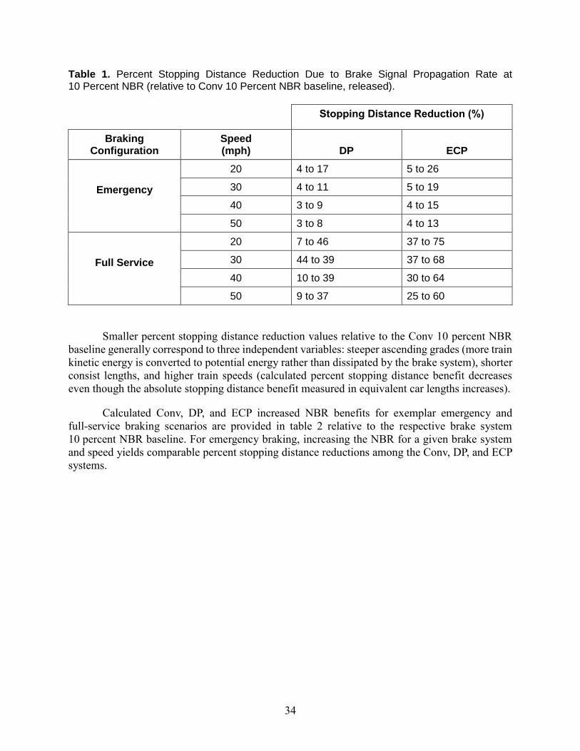
34
Table 1. Percent Stopping Distance Reduction Due to Brake Signal Propagation Rate at 10 Percent NBR (relative to Conv 10 Percent NBR baseline, released).
Stopping Distance Reduction (%)
Braking Configuration
Speed (mph)
DP
ECP
Emergency
20 4 to 17 5 to 26
30 4 to 11 5 to 19
40 3 to 9 4 to 15
50 3 to 8 4 to 13
Full Service
20 7 to 46 37 to 75
30 44 to 39 37 to 68
40 10 to 39 30 to 64
50 9 to 37 25 to 60
Smaller percent stopping distance reduction values relative to the Conv 10 percent NBR
baseline generally correspond to three independent variables: steeper ascending grades (more train
kinetic energy is converted to potential energy rather than dissipated by the brake system), shorter
consist lengths, and higher train speeds (calculated percent stopping distance benefit decreases
even though the absolute stopping distance benefit measured in equivalent car lengths increases).
Calculated Conv, DP, and ECP increased NBR benefits for exemplar emergency and
full-service braking scenarios are provided in table 2 relative to the respective brake system
10 percent NBR baseline. For emergency braking, increasing the NBR for a given brake system
and speed yields comparable percent stopping distance reductions among the Conv, DP, and ECP
systems.
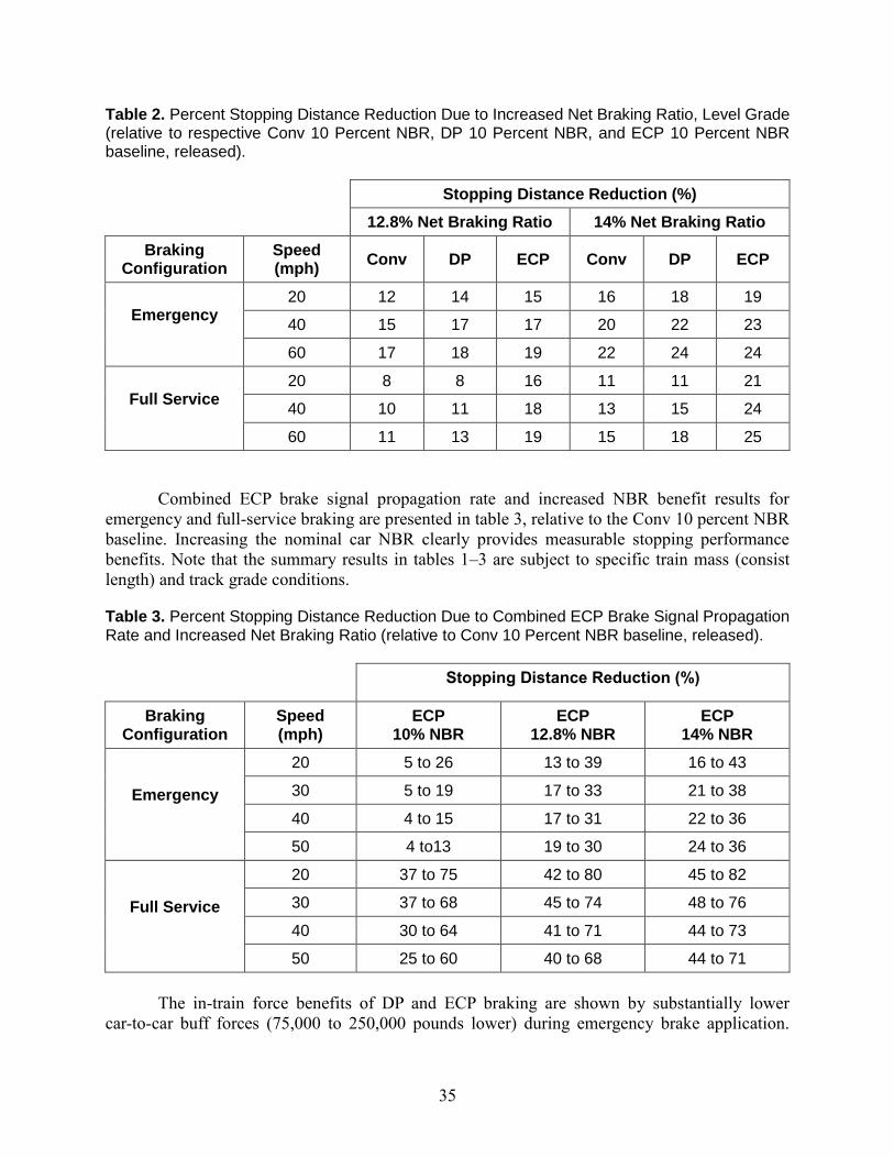
35
Table 2. Percent Stopping Distance Reduction Due to Increased Net Braking Ratio, Level Grade (relative to respective Conv 10 Percent NBR, DP 10 Percent NBR, and ECP 10 Percent NBR baseline, released).
Stopping Distance Reduction (%)
12.8% Net Braking Ratio 14% Net Braking Ratio
Braking Configuration
Speed (mph)
Conv DP ECP Conv DP ECP
Emergency 20 12 14 15 16 18 19
40 15 17 17 20 22 23
60 17 18 19 22 24 24
Full Service 20 8 8 16 11 11 21
40 10 11 18 13 15 24
60 11 13 19 15 18 25
Combined ECP brake signal propagation rate and increased NBR benefit results for
emergency and full-service braking are presented in table 3, relative to the Conv 10 percent NBR
baseline. Increasing the nominal car NBR clearly provides measurable stopping performance
benefits. Note that the summary results in tables 1–3 are subject to specific train mass (consist
length) and track grade conditions.
Table 3. Percent Stopping Distance Reduction Due to Combined ECP Brake Signal Propagation Rate and Increased Net Braking Ratio (relative to Conv 10 Percent NBR baseline, released).
Stopping Distance Reduction (%)
Braking Configuration
Speed (mph)
ECP 10% NBR
ECP 12.8% NBR
ECP 14% NBR
Emergency
20 5 to 26 13 to 39 16 to 43
30 5 to 19 17 to 33 21 to 38
40 4 to 15 17 to 31 22 to 36
50 4 to13 19 to 30 24 to 36
Full Service
20 37 to 75 42 to 80 45 to 82
30 37 to 68 45 to 74 48 to 76
40 30 to 64 41 to 71 44 to 73
50 25 to 60 40 to 68 44 to 71
The in-train force benefits of DP and ECP braking are shown by substantially lower
car-to-car buff forces (75,000 to 250,000 pounds lower) during emergency brake application.
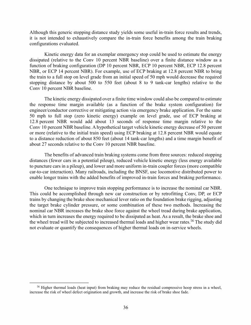
36
Although this generic stopping distance study yields some useful in-train force results and trends,
it is not intended to exhaustively compare the in-train force benefits among the train braking
configurations evaluated.
Kinetic energy data for an exemplar emergency stop could be used to estimate the energy
dissipated (relative to the Conv 10 percent NBR baseline) over a finite distance window as a
function of braking configuration (DP 10 percent NBR, ECP 10 percent NBR, ECP 12.8 percent
NBR, or ECP 14 percent NBR). For example, use of ECP braking at 12.8 percent NBR to bring
the train to a full stop on level grade from an initial speed of 50 mph would decrease the required
stopping distance by about 500 to 550 feet (about 8 to 9 tank-car lengths) relative to the
Conv 10 percent NBR baseline.
The kinetic energy dissipated over a finite time window could also be compared to estimate
the response time margin available (as a function of the brake system configuration) for
engineer/conductor corrective or mitigating action via emergency brake application. For the same
50 mph to full stop (zero kinetic energy) example on level grade, use of ECP braking at
12.8 percent NBR would add about 13 seconds of response time margin relative to the
Conv 10 percent NBR baseline. A hypothetical target vehicle kinetic energy decrease of 50 percent
or more (relative to the initial train speed) using ECP braking at 12.8 percent NBR would equate
to a distance reduction of about 850 feet (about 14 tank-car lengths) and a time margin benefit of
about 27 seconds relative to the Conv 10 percent NBR baseline.
The benefits of advanced train braking systems come from three sources: reduced stopping
distances (fewer cars in a potential pileup), reduced vehicle kinetic energy (less energy available
to puncture cars in a pileup), and lower and more uniform in-train coupler forces (more compatible
car-to-car interaction). Many railroads, including the BNSF, use locomotive distributed power to
enable longer trains with the added benefits of improved in-train forces and braking performance.
One technique to improve train stopping performance is to increase the nominal car NBR.
This could be accomplished through new car construction or by retrofitting Conv, DP, or ECP
trains by changing the brake shoe mechanical lever ratio on the foundation brake rigging, adjusting
the target brake cylinder pressure, or some combination of these two methods. Increasing the
nominal car NBR increases the brake shoe force against the wheel tread during brake application,
which in turn increases the energy required to be dissipated as heat. As a result, the brake shoe and
the wheel tread will be subjected to increased thermal loads and higher wear rates.56 The study did
not evaluate or quantify the consequences of higher thermal loads on in-service wheels.
56 Higher thermal loads (heat input) from braking may reduce the residual compressive hoop stress in a wheel,
increase the risk of wheel defect origination and growth, and increase the risk of brake shoe fade.