bms information - windcatcher x-air - ellisco€¦ · controls by monodraught bms information -...
TRANSCRIPT

Controls by Monodraught
BMS Information - WINDCATCHER X-Air
A Building Management System (BMS) is a control system that can be used to monitor and manage the mechanical, electrical and electromechanical services within a facility.
In its most basic form, a BMS consists of software, a server with a database and smart sensors connected to an internet-capable network. The smart sensors situated throughout the building will gather data and send it to the BMS, where it is then stored in a database.
The data collected can then be used to control a number of different aspects of the building; including power, heating, ventilation and air-conditioning, etc. This makes connecting a Monodraught control system to a BMS very useful as it will allow for a Monodraught Natural Ventilation or Cooling product to be automatically controlled, dependant on pre-defined conditions.
When using the WINDCATCHER® X-Air to Naturally Ventilate a space, a WINDCATCHER X-Air wall controller can be connected to the BMS to provide temperature, override and optional CO2 information. This will allows the WINDCATCHER system to be controlled in order to create a comfortable and healthy environment by means of expelling stale air from the room and supplying fresh air from outside.
The Monodraught WINDCATCHER X-Air wall mounted controller can be connected to the BMS via a three core cable (16-2-3A. RS: 660-4087 or Farnell 1190282) as follows:
Red 24V DCGreen 0 - 10V signal (conveying Temperature, Override and optional CO2 information)Blue 0V DC
[email protected] / +44 (0)1494 [email protected] / +44 (0)1494 897700 32
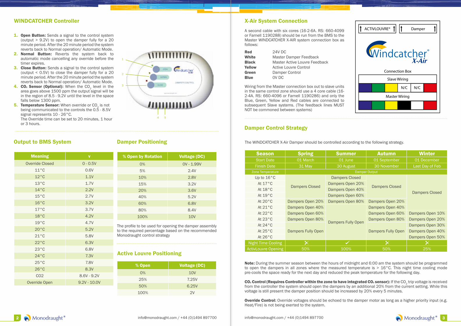
WINDCATCHER Controller
1. Open Button: Sends a signal to the control system (output > 9.2V) to open the damper fully for a 20 minute period. After the 20 minute period the system reverts back to Normal operation/ Automatic Mode.
2. Normal Button: Reverts the system back to automatic mode cancelling any override before the timer expires.
3. Close Button: Sends a signal to the control system (output < 0.5V) to close the damper fully for a 20 minute period. After the 20 minute period the system reverts back to Normal operation/ Automatic Mode.
4. CO2 Sensor (Optional): When the CO2 level in the area goes above 1500 ppm the output signal will be in the region of 8.5 - 9.2V until the level in the space falls below 1300 ppm.
5. Temperature Sensor: When override or CO2 is not being communicated to the controls the 0.5 - 8.5V signal represents 10 - 26°C. The Override time can be set to 20 minutes, 1 hour or 3 hours.
Damper Control Strategy
Note: During the summer season between the hours of midnight and 6:00 am the system should be programmed to open the dampers in all zones where the measured temperature is > 16°C. This night time cooling mode pre-cools the space ready for the next day and reduced the peak temperature for the following day.
CO2 Control (Requires Controller within the zone to have integrated CO2 sensor): If the CO2 trip voltage is received from the controller the system should open the dampers by an additional 20% from the current setting. While this voltage is still present the damper position should be increased by 20% every 5 minutes.
Override Control: Override voltages should be echoed to the damper motor as long as a higher priority input (e.g. Heat/Fire) is not being exerted to the system.
Output to BMS System
Meaning v
Override Closed 0 - 0.5V
11°C 0.6V
12°C 1.1V
13°C 1.7V14°C 2.2V15°C 2.7V
16°C 3.2V
17°C 3.7V
18°C 4.2V
19°C 4.7V
20°C 5.2V
21°C 5.8V
22°C 6.3V
23°C 6.8V
24°C 7.3V
25°C 7.8V
26°C 8.3V
CO2 8.6V - 9.2V
Override Open 9.2V - 10.0V
Damper Positioning
% Open by Rotation Voltage (DC)
0% 0V - 1.99V
5% 2.4V
10% 2.8V
15% 3.2V20% 3.6V40% 5.2V
60% 6.8V
80% 8.4V
100% 10V
Active Louvre Positioning
% Open Voltage (DC)
0% 10V
25% 7.25V
50% 6.25V
100% 2V
The profile to be used for opening the damper assembly to the required percentage based on the recommended Monodraught control strategy
X-Air System Connection
A second cable with six cores (16-2-6A. RS: 660-4099 or Farnell 1190288) should be run from the BMS to the Master WINDCATCHER X-AIR system connection box as follows:
Red 24V DCWhite Master Damper Feedback Black Master Active Louvre Feedback Yellow Active Louvre Control Green Damper Control Blue 0V DC
Wiring from the Master connection box out to slave units in the same control zone should use a 4 core cable (16-2-4A. RS: 660-4096 or Farnell 1190286) and only the Blue, Green, Yellow and Red cables are connected to subsequent Slave systems. (The feedback lines MUST NOT be commoned between systems)
ACTIVLOUVRE® Damper
Slave Wiring
Master Wiring
Connection Box
N/C N/C
Season Spring Summer Autumn WinterStart Date 01 March 01 June 01 September 01 DecemberFinish Date 31 May 30 August 30 November Last Day of Feb
Zone Temperature Damper Output
Up to 16°C
Dampers Closed
Dampers Closed
Dampers ClosedDampers Closed
At 17°C Dampers Open 20%At 18°C Dampers Open 40%At 19°C Dampers Open 60%At 20°C Dampers Open 20% Dampers Open 80% Dampers Open 20%At 21°C Dampers Open 40%
Dampers Fully Open
Dampers Open 40%At 22°C Dampers Open 60% Dampers Open 60% Dampers Open 10%At 23°C Dampers Open 80% Dampers Open 80% Dampers Open 20%At 24°C
Dampers Fully Open Dampers Fully OpenDampers Open 30%
At 25°C Dampers Open 40%At 26°C Dampers Open 50%
Night Time CoolingActivLouvre Opening 50% 100% 50% 25%
The WINDCATCHER X-Air Damper should be controlled according to the following strategy.

Additional Input Control Parameters
RainThe systems should ignore temperature and CO2 control and CLOSE immediately on rain. Higher priorities should be actioned. (Override and Fire etc.).
Heating InterlockThe Dampers should ignore temperature control and be set to 10% or 20%. Higher Priorities should still be actioned.
External Temperature (ET) (if available)Can be used to season shift as shown as in the table below.
It can also be used in real time for closing the systems if the external temperature is below 5°C for the Snow/Frost Mode (As Rain mode with Rain Priority). Also the dampers can be set to ignore temperature control when the external temperature is more than 3°C above internal and the internal is above a high temp threshold (Usually 25°C internal and > 28°C external).
Input Priority List
There are priorities associated with each input so that certain inputs override others, such as Fire Alarm input overriding the CO2 mode. This is shown in the table on the below. The CO2 and heating interlock priorities can be swapped via configuration settings.
Input Priority1 Fire Key Switch Highest
2 Fire Alarm
3 Competition Switch
4 Override Open
5 Override Close
6 Rain/Snow/Frost Protection
7 CO2
8 Heating Interlock
9 Temperature Lowest
Current Calendar Season Spring Summer Autumn WinterExternal Temp (ET) Operational Season for Next 24 Hours
ET < 8°C Winter Spring Winter Winter
8°C < ET < 15°C Spring Spring Autumn Winter
15°C < ET < 22°C Spring Summer Autumn Spring
22°C < ET Summer Summer Summer Spring
Halifax House, High WycombeBuckinghamshire, HP12 3SE
www.monodraught.com