bms design guide
TRANSCRIPT

7/23/2019 BMS Design Guide
http://slidepdf.com/reader/full/bms-design-guide 1/90
BMS Design

7/23/2019 BMS Design Guide
http://slidepdf.com/reader/full/bms-design-guide 2/90
CONTENTS
Preface
The purpose of this document is to help the users to understand how the instrumentation of air-conditioningsystem works. There are various types of instrumentation systems such as electric, electronic and direct digitalcontrol (DDC) systems, which can be used to control the air handling unit (AHU). This document includes anumber of examples with the emphasis placed on electronic and electrical instrumentation. The Appropriatemethod must be selected after studying the various conditions such as how the system will be used, likelyoperating conditions, degree of control accuracy required, consistency of all facilities, etc.Contact the Yamatake representatives for further information on actual instrumentation and design.
Part I
1. Building Management System1.1 What is building management system? ................................................................................................. 1
1.2 The Advantages of Building Management System ................................................................................ 4
2. Fundamentals of Automatic Control2.1 General of Automatic Control ................................................................................................................ 5
2.2 Automatic Control Methodology ............................................................................................................ 7
2.3 Application fo Automatic Control device ................................................................................................ 9
2.4 BMS & Automatic control design general .............................................................................................. 11
2.5 Automatic Control System Design Procedure ........................................................................................ 15
2.6 Automatic Control System Retrofit Planning Procedure ........................................................................ 17
3. Automatic Control Devices3.1 Electric Control Devices ........................................................................................................................ 19
3.2 Electronic Control Devices .................................................................................................................... 19
3.3 DDC (Direct Digital Control) .................................................................................................................. 21
3.4 Intelligent Component ........................................................................................................................... 24
4. HVAC System generals4.1 AHU Systems ........................................................................................................................................ 25
4.2 Chiller Plant Systems ............................................................................................................................ 26
5. Control Functions5.1 HVAC Automatic Control details ............................................................................................................ 27
5.2 Energy saving application ..................................................................................................................... 30
6. Typical Instrumentation Examples
6.1 Examples of Automatic Control System Instrumentation ....................................................................... 35
Part II
Guide Specification for HVAC
7/23/2019 BMS Design Guide
http://slidepdf.com/reader/full/bms-design-guide 3/90
1
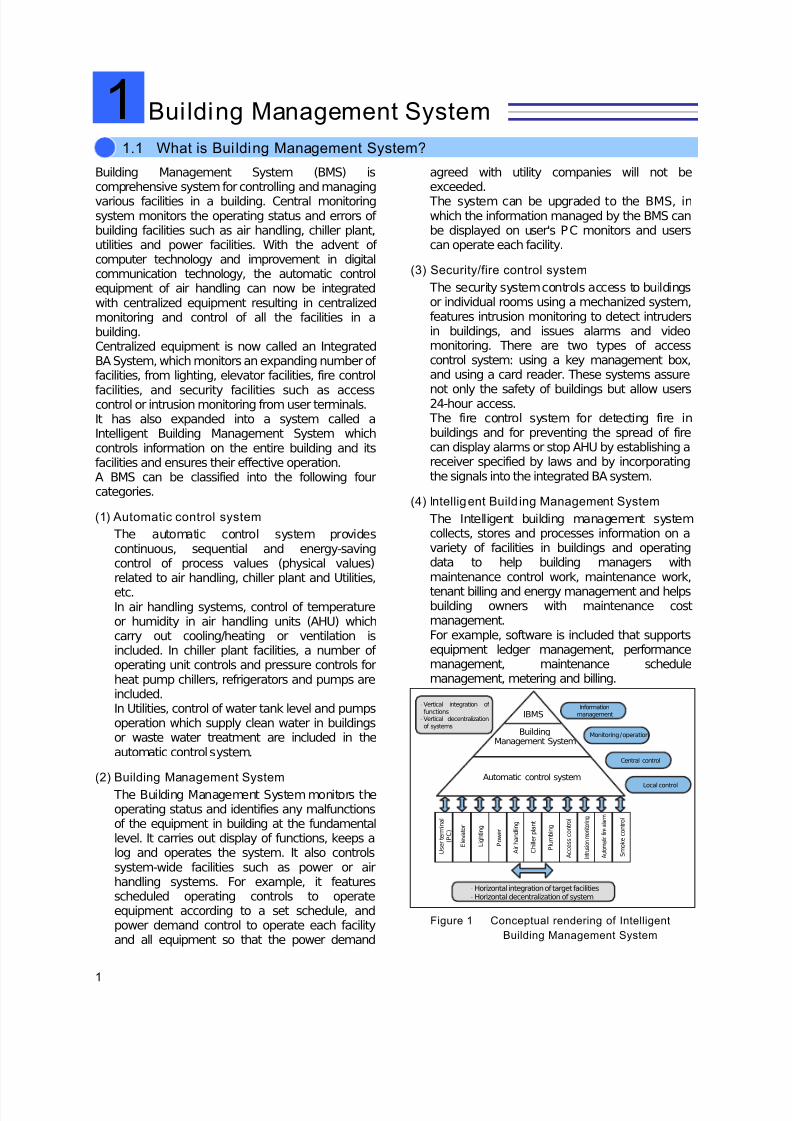
1 Building Automat ion
Building Management System (BMS) iscomprehensive system for controlling and managingvarious facilities in a building. Central monitoringsystem monitors the operating status and errors of building facilities such as air handling, chiller plant,utilities and power facilities. With the advent of computer technology and improvement in digitalcommunication technology, the automatic controlequipment of air handling can now be integratedwith centralized equipment resulting in centralizedmonitoring and control of all the facilities in abuilding.Centralized equipment is now called an IntegratedBA System, which monitors an expanding number of facilities, from lighting, elevator facilities, fire control
facilities, and security facilities such as accesscontrol or intrusion monitoring from user terminals.It has also expanded into a system called aIntelligent Building Management System whichcontrols information on the entire building and itsfacilities and ensures their effective operation.A BMS can be classified into the following fourcategories.
(1) Automatic control system
The automatic control system providescontinuous, sequential and energy-savingcontrol of process values (physical values)related to air handling, chiller plant and Utilities,
etc.In air handling systems, control of temperatureor humidity in air handling units (AHU) whichcarry out cooling/heating or ventilation isincluded. In chiller plant facilities, a number of operating unit controls and pressure controls forheat pump chillers, refrigerators and pumps areincluded.In Utilities, control of water tank level and pumpsoperation which supply clean water in buildingsor waste water treatment are included in theautomatic control system.
(2) Building Management System
The Building Management System monitors theoperating status and identifies any malfunctionsof the equipment in building at the fundamentallevel. It carries out display of functions, keeps alog and operates the system. It also controlssystem-wide facilities such as power or airhandling systems. For example, it featuresscheduled operating controls to operateequipment according to a set schedule, andpower demand control to operate each facilityand all equipment so that the power demand
agreed with utility companies will not beexceeded. The system can be upgraded to the BMS, inwhich the information managed by the BMS canbe displayed on user's PC monitors and userscan operate each facility.
(3) Security/fire control system
The security system controls access to buildingsor individual rooms using a mechanized system,features intrusion monitoring to detect intrudersin buildings, and issues alarms and videomonitoring. There are two types of accesscontrol system: using a key management box,and using a card reader. These systems assure
not only the safety of buildings but allow users24-hour access. The fire control system for detecting fire inbuildings and for preventing the spread of firecan display alarms or stop AHU by establishing areceiver specified by laws and by incorporatingthe signals into the integrated BA system.
(4) Intelligent Build ing Management System
The Intelligent building management systemcollects, stores and processes information on avariety of facilities in buildings and operatingdata to help building managers withmaintenance control work, maintenance work,
tenant billing and energy management and helpsbuilding owners with maintenance costmanagement.For example, software is included that supportsequipment ledger management, performancemanagement, maintenance schedulemanagement, metering and billing.
Figure 1 Conceptual rendering of Intelligent
Building Management System
1.1 What is Bui lding Management System?
I n t r u s i o n m o n i t o r i n g
⋅ Vertical integration of functions
⋅ Vertical decentralizationof systems
Informationmanagement
Monitoring / operation
Central control
Local control
IBMS
BuildingManagement System
Automatic control system
U s e r t e r m i n a l
( P C )
E l e v a t o r
L i g h t i n g
P o w e r
A i r h a n d l i n g
C h i l l e r p l a n t
P l u m b i n g
A c c e s s c o n t r o l
A u t o m a t i c f i r e a l a r m
S m o k e c o n t r o l
⋅ Horizontal integration of target facilities⋅ Horizontal decentralization of system
Building Management System1
7/23/2019 BMS Design Guide
http://slidepdf.com/reader/full/bms-design-guide 4/90
2
1 Building Management System
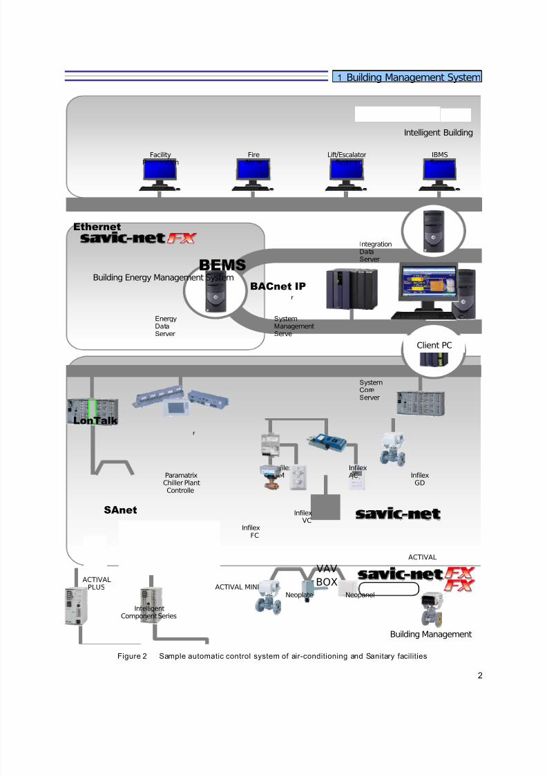
Figure 2 Sample automatic control system of air-conditioning and Sanitary facilities
IBMSServer
FacilityReservation
FireAlarm
Lift/EscalatorSystem
SystemManagement Serve
IntelligentComponent Series
Energy Data Server
Integration Data Server
Ethernet
BACnet IP
SystemCore Server
LonTalk
SAnet
ParamatrixChiller PlantControlle
ACTIVALPLUS
BEMSBuilding Energy Management System
InfilexVC
VAV
BOX
InfilexZM
InfilexFC
ACTIVAL MININeoplate Neopanel
Client PC
InfilexGD
InfilexAC
ACTIVAL
Intelligent Building
Building Management

7/23/2019 BMS Design Guide
http://slidepdf.com/reader/full/bms-design-guide 5/90
3
1 Building Management System
Figure 3 Sample integrated BA system
AssetManagement
HelpDesk
FacilityManagement
MultimediaPublic Display
DataStorageServe
SecurityDataServer
BACnet IP
ProximityCardReaderIR
PassiveSensor
ElectricLock
AccessCore
Controller
Wiegand
Modbus
Interface
PLC
Power meter
PipeInsertion
TemperatureSensors
DuctInsertion
TemperatureHumiditySensors
CO2Concentration Transmitter
OperatorPanel
Room Temperature
HumiditySensor
InfilexGC
ACTIVAL
BACnet
Devices
Lighting
System
3rd Party
LonTalk
Devices
OPC
Server
CCTV
SecuritySecuritySystem
Management System
IBMS
System
BMS
7/23/2019 BMS Design Guide
http://slidepdf.com/reader/full/bms-design-guide 6/90
4
1 Building Management System
The advantages of introducing a BuildingManagement System to users of buildings includethe provision of a comfortable, safe and convenientenvironment. The advantages to owners andmanagers include reduction of operating costs bymeans of energy conservation and labor-savingover the entire building as well as bettermaintenance, leading to improvement of the value of property. The BMS clearly affords a variety of
benefits.In particular, the automatic air-conditioning controlsystem allows the creation of the most comfortableenvironment for users, prevents wastage of energyby optimum control and continuously maintainsthese advantages. Introducing BMS. The detailedbenefits of introduction are as follows:
(1) Labor-saving, efficient management
Since integration allows comprehensive controlof large amounts of data, operation of building
and facilities can be carried out by a smallernumber of people. More sophisticatedmanagement can be realized through effectiveuse of the information.
(2) Maintenance and optimization of
environment
Maintains optimum thermal environmentcondition, such as temperature and humidityincluding CO2 and dust requirements, as well as
lighting levels for individual users or productionfacilities.
(3) Resource/energy saving
Utilizing natural energy effectively and limitingunnecessary use of resources or energy, usingthe methods like controlling and maintaining adesired temperature setting accurately, or byemploying only outdoor air necessary to carry
out control in response to the load placed in thebuilding.
(4) Ensures a variety of safety features
By concentrating all information about buildingfacilities into the central unit, you can easily
identify the status of facilities, operate thefacilities and take correct countermeasures inthe event of power failure or outbreak of fire. Byintegration with the security system, you canassure the safety of building users andconfidential information with no loss of convenience.
(5) Improve convenience for building users
By integrating each facility, services andconvenience to individual users can be improved.For example, 24-hour free safe access tobuildings, simple and user-friendly setting and
adjustment of temperature or operating time andidentification of outdoor air temperature, weatherstatus and building management information. The following pages illustrate a sampleautomatic control system for air-conditioning andutilities, and a sample integrated BA system.
1.2 The Advantages of Bui lding Management System
7/23/2019 BMS Design Guide
http://slidepdf.com/reader/full/bms-design-guide 7/90
5
This section describes the mechanism of automaticcontrol, important factors in air handling controlincluding temperature, humidity, pressure, flow rate,response, methods and how to read theimplementation diagrams as well as notes fordesigning automatic control systems.
Please note that to make the descriptions in thisdocument simpler and easier to understand, somenon-technical expressions may be used in thesections describing the theory of automatic control.
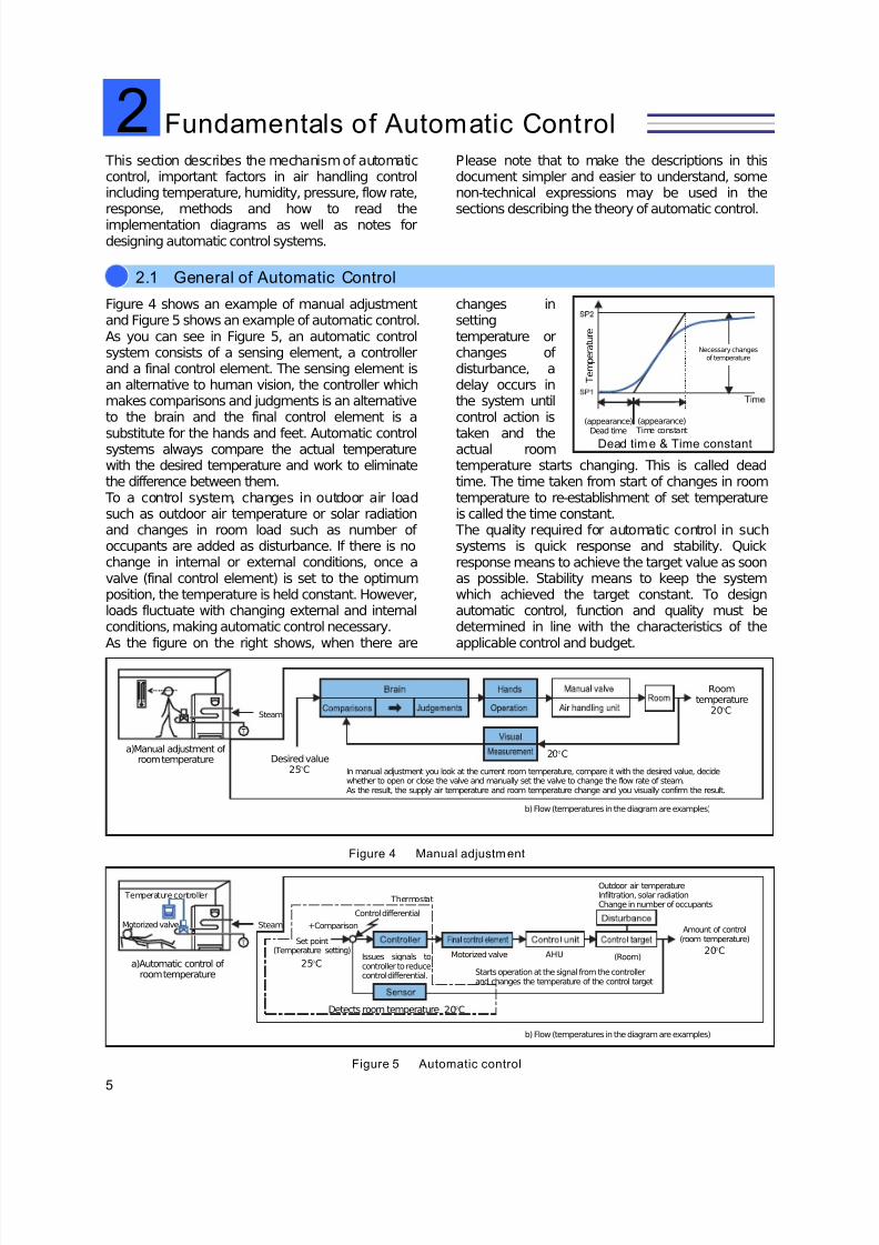
Figure 4 shows an example of manual adjustmentand Figure 5 shows an example of automatic control.As you can see in Figure 5, an automatic controlsystem consists of a sensing element, a controllerand a final control element. The sensing element isan alternative to human vision, the controller whichmakes comparisons and judgments is an alternativeto the brain and the final control element is a
substitute for the hands and feet. Automatic controlsystems always compare the actual temperaturewith the desired temperature and work to eliminatethe difference between them. To a control system, changes in outdoor air loadsuch as outdoor air temperature or solar radiationand changes in room load such as number of occupants are added as disturbance. If there is nochange in internal or external conditions, once avalve (final control element) is set to the optimumposition, the temperature is held constant. However,loads fluctuate with changing external and internalconditions, making automatic control necessary.As the figure on the right shows, when there are
changes insettingtemperature orchanges of disturbance, adelay occurs inthe system untilcontrol action is
taken and theactual roomtemperature starts changing. This is called deadtime. The time taken from start of changes in roomtemperature to re-establishment of set temperatureis called the time constant. The quality required for automatic control in suchsystems is quick response and stability. Quickresponse means to achieve the target value as soonas possible. Stability means to keep the systemwhich achieved the target constant. To designautomatic control, function and quality must bedetermined in line with the characteristics of theapplicable control and budget.
Figure 4 Manual adjustment
Figure 5 Automatic control
Fundamentals of Automatic Control2
2.1 General of Automatic Control
(appearance)Dead time
(appearance) Time constant
Necessary changesof temperature
T e m p e r a
t u r e
Dead time & Time constant
a)Manual adjustment of room temperature Desired value
25°C
Roomtemperature
20°C
20°C
In manual adjustment you look at the current room temperature, compare it with the desired value, decidewhether to open or close the valve and manually set the valve to change the flow rate of steam.As the result, the supply air temperature and room temperature change and you visually confirm the result.
b) Flow (temperatures in the diagram are examples)
Steam
Issues signals tocontroller to reducecontrol differential.
Set point
20°C
a)Automatic control of room temperature Starts operation at the signal from the controller
and changes the temperature of the control target
AHU (Room)
Outdoor air temperatureInfiltration, solar radiationChange in number of occupants
Amount of control(room temperature)
20°C
b) Flow (temperatures in the diagram are examples)
+Comparison
Control differential
Thermostat
(Temperature setting)
Detects room temperature
Steam
25°CMotorized valve
Temperature controller
Motorized valve
7/23/2019 BMS Design Guide
http://slidepdf.com/reader/full/bms-design-guide 8/90
6
2 Fundamentals of Automatic Control
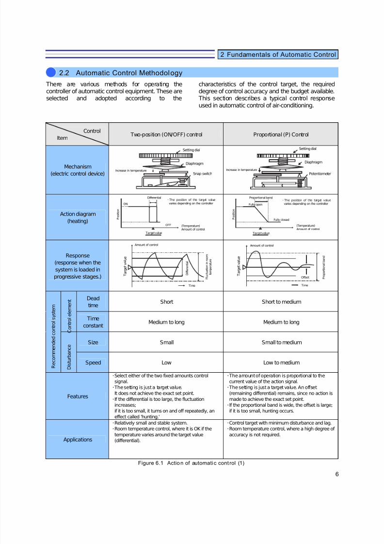
There are various methods for operating thecontroller of automatic control equipment. These areselected and adopted according to the
characteristics of the control target, the requireddegree of control accuracy and the budget available. This section describes a typical control responseused in automatic control of air-conditioning.
Control
Item Two-position (ON/OFF) control Proportional (P) Control
Mechanism
(electric control device)
Action diagram
(heating)
Response
(response when the
system is loaded in
progressive stages.)
Dead
timeShort Short to medium
Time
constantMedium to long Medium to long
Size Small Small to medium
Speed Low Low to medium
Features
・Select either of the two fixed amounts control
signal.・ The setting is just a target value.
It does not achieve the exact set point.
・If the differential is too large, the fluctuation
increases;
if it is too small, it turns on and off repeatedly, an
effect called 'hunting.'
・ The amount of operation is proportional to the
current value of the action signal.・ The setting is just a target value. An offset
(remaining differential) remains, since no action is
made to achieve the exact set point.
・If the proportional band is wide, the offset is large;
if it is too small, hunting occurs.
Applications
・Relatively small and stable system.
・Room temperature control, where it is OK if the
temperature varies around the target value
(differential).
・Control target with minimum disturbance and lag.
・Room temperature control, where a high degree of
accuracy is not required.
Figure 6.1 Action of automati c cont rol (1)
R e c o m m e n d e d c o n t r o l s y s t e m
C o n t r o l e l e m e n t
D i s t u r b a n c e
Differential
Target value
(Temperature) Amount of control
・ The position of the target valuevaries depending on the controller
P o s i t i o n
Setting dial
Diaphragm
Snap switchIncrease in temperature
Setting dial
Diaphragm
PotentiometerIncrease in temperature
Proportional band
Target value
(Temperature)Amount of control
・ The position of the target valuevaries depending on the controller
P o s i t i o n
Fully open
Fully closed
Amount of control
Time
F l u c t u a t i o n i n r o o m
t e m p e r a t u r e
D i f f e r e n t i a l
T a r g e t v a l u e
Amount of control
Time
P r o p o r t i o n a l b a n d
Offset T a r g e t v a l u e
2.2 Automatic Control Methodology

7/23/2019 BMS Design Guide
http://slidepdf.com/reader/full/bms-design-guide 9/90
7
2 Fundamentals of Automatic Control
Control
ItemFloating Control Proportional +Integral (PI) Control
Proportional +Integral +Derivative
(PID)Control
Action diagram
(heating)
Response
(response when
disturbance is added in
the systems loaded in
progressive stages.)
Dead
timeShort Short to medium Short to long
Timeconstant
Short Short to long Short to long
Size Small to large Small to large Small to large
Speed Low Low to medium Low to high
Features
・When an action signal exceeds acertain range(dead band),itincreases/decreases the amount of operation at a certain speed.・ The setting is just a target value.It does not achieve the exact setpoint.
・Adds the integral action to theproportional action to eliminate offsetand keeps the control target at orvery near the set point
・Adds a derivative function to thePI control. Provides a fasterresponse.
Applications
・System with minimum lag and timeconstant ; disturbance can be large.・ Tank level control, etc.
・Systems with large disturbance・Room temperature control orpressure control where supply airtemperature control or high degree of accuracy is required.
・System where there aresignificant load changes and ahigh degree of accuracy isrequired.・Special constant temperature and constant humidity control,pressure control, etc.
Notes:P:
I :
D:
Proportional
Integral
Derivative
Figure 6.2 Action of Automatic Contro l (2)
R e c o m m e n d e d c o n t r
o l s y s t e m
C o n t r o l e l e m e n t
D i s t u r b a n c e
Set pointProportional
band
(Temperature)Amount
of control
A m o u n t o f o p e r a t i o n
Amount of control
Time
P o s i t i o n
D e a d b a n d
Amount of control
Time
S e t p o i n t
P r o p o r t i o n a l b a n d
Off
Increase in amountof operation
Target value
Dead band
(Temperature)amount
of control
D i a p h r a g m Decrease in
amount of operation
A m o u n t o f o p e r a t i o n
(Temperature)Amount
of control
ProportionalbandSet point
Amount of control
Time
S e t p o i n t
P r o p o r t i o n a l b a n d

7/23/2019 BMS Design Guide
http://slidepdf.com/reader/full/bms-design-guide 10/90
8
2 Fundamentals of Automatic Control
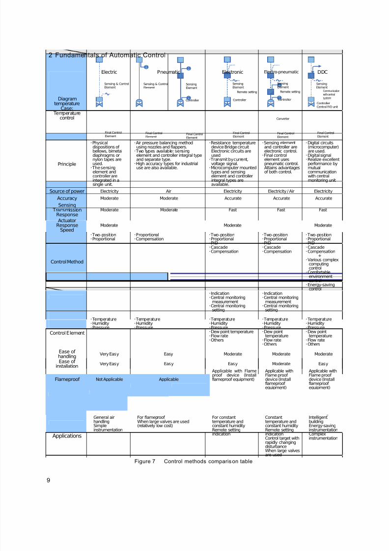
According to its principle and structure, theautomatic control equipment for air handling isclassified as follows:(See Figure 7 on the next page).
• Electric• Electronic• Pneumatic• Electro-pneumatic• Direct Digital Control (DDC)
These methods are chosen for their specificcharacteristics (Figure 7, next page).With the recent digitalization of products, it is gettingmore difficult to categorize these methods simply
according to their operating principle and structure.Please note that in this document some devices areregarded as electronic due to how they are applied,even if they use built-in digital circuits. The structure,operating principle and type of each device isexplained in Section 3.
In J apan, compared with America and Europe,pneumatic/electro-pneumatic methods usingpneumatic pressure as the input signal are found inonly a few applications, such as chiller plant controlor explosion-proof systems, where large valves areused, or hospitals, where many valves are used.In electric control devices, mechanical elementssuch as diaphragms or nylon tapes are used andsensing elements and a controller are included in asingle unit. These devices are commonly used asthey are convenient to handle and feature low cost.However, it is expected that these devices will bereplaced by electronic digitized products with asimilar appearance. Microprocessors areincreasingly being mounted on electronic devices,
but DDC is becoming even more widespread.Further details on DDC are given in Section 3.3.Here, DDC is categorized as a product that obtainsvarious function and benefits by communicating withmain building management system. In this regard, itis different from electronic devices with microprocessors.
2.3 Application for Automatic Control Device
7/23/2019 BMS Design Guide
http://slidepdf.com/reader/full/bms-design-guide 11/90
9
2 Fundamentals of Automatic Control
Electric Pneumatic Electronic Electro-pneumatic DDC
Diagramtemperature
Case: Temperature
control
Principle
・Physicaldispositions of bellows, bimetaldiaphragms ornylon tapes areused.・ The sensingelement andcontroller areintegrated in asingle unit.
・Air pressure balancing methodusing nozzles and flappers.・ Two types available: sensingelement and controller integral typeand separate type.・High accuracy types for industrialuse are also available.
・Resistance temperaturedevice Bridge circuitElectronic circuits areused・ Transmit by current,voltage signal.・Microcomputer mountedtypes and sensingelement and controllerintegral types areavailable.
・Sensing elementand controller areelectronic control.・Final controlelement usespneumatic control.Attains advantagesof both control.
・Digital circuits(microcomputer)are used.・Digital signal・Realize excellentperformance bymutualcommunicationwith centralmonitoring unit
Source of power Electricity Air Electricity Electricity / Air ElectricityAccuracy Moderate Moderate Accurate Accurate Accurate
Sensing Transmission
ResponseModerate Moderate Fast Fast Fast
ActuatorResponse
SpeedModerate Moderate Moderate
Control Method
・ Two-position・Proportional
・Proportional・Compensation
・ Two-position・Proportional・PID・Cascade・Compensation
・ Two-position・Proportional・PID・Cascade・Compensation
・ Two-position・Proportional・PID・Cascade・Compensation
+・Various complex
computingcontrol・Comfortable
environmentcontrol・Energy-saving
control
Function
・Indication・Central monitoring
measurement・Central monitoring
setting
・Indication・Central monitoring
measurement・Central monitoring
setting
Control Element
・ Temperature・Humidity・Pressure
・ Temperature・Humidity・Pressure
・ Temperature・Humidity・Pressure・Dew point temperature・Flow rate・Others
・ Temperature・Humidity・Pressure・Dew point
temperature・Flow rate・Others
・ Temperature・Humidity・Pressure・Dew point
temperature・Flow rate・Others
Ease of handling
Very Easy Easy Moderate Moderate Moderate
Ease of installation
Very Easy Easy Easy Moderate Easy
Flameproof Not Applicable Applicable
Applicable with Flameproof device (Installflameproof equipment)
Applicable withFlame proof device (Installflameproof equipment)
Applicable withFlame proof device (Installflameproof equipment)
Cost efficiency
Low cost, providedtheinstrumentation issimple.
Low cost, provided theinstrumentation is simple.(air source equipment is required)
More expensive thanan electric controlsystem.
Comparatively lowcost ininstrumentationwith many valves.
Less expensivethan an electriccontrol system if it is used withcentralmonitoring unit
Applications
General airhandlingSimpleinstrumentation
For flameproof When large valves are used(relatively low cost)
For constanttemperature andconstant humidityRemote settingindication
Constanttemperature andconstant humidityRemote settingindicationControl target withrapidly changingdisturbanceWhen large valvesare used
IntelligentbuildingEnergy-savinginstrumentationComplexinstrumentation
Figure 7 Control methods comparison table
Controller
SensingElement
Final ControlElement
Central F/O unit
Communicationwith centralsystem
SensingElement
Final ControlElement
Converter
Controller
Remote setting
Sensing & ControlElement
Final Control Element
Final ControlElement
Sensing & ControlElement
Final ControlElement
SensingElement
Controller
Final ControlElement
SensingElement
Controller
Remote setting
7/23/2019 BMS Design Guide
http://slidepdf.com/reader/full/bms-design-guide 12/90
10
2 Fundamentals of Automatic Control
At first glance, diagrams of automatic controls forair-handling look confusing and off-putting. However,it is possible to understand the drawing more easilyif you learn a few rules. (Different manufacturers
tend to use slightly different rules). Normally,drawings of BMS including central monitoring andautomatic controls are composed of the followingitems.
1. Automatic control Drawing
2. Legend Table for automati c control devices
3. Valve s ize table
4. Automatic control (remote) panel dimensions table
5. Central monitoring system block di agram
6. Central monit oring system specifications
7. Central monit oring system di mension diagram
8. Central monitoring system I/O hardware interface wiring circuit diagram
9. Central monitoring system input and output list I/O table
10.BMS & Automatic co ntrol f low wi ring plan
Work segment diagram and central monitoringsystem diagrams may be added to these drawings.In particular, instrumentation diagrams in which the
functions and systems of automatic control areentered with an overview of facilities enable theviewer to fully understand the automatic controlsystem. This section contains an explanation of the symbolsused in this diagram.
In addition, some typical examples of instrumentation diagrams of air-conditioningfacilities are shown in Section 6.
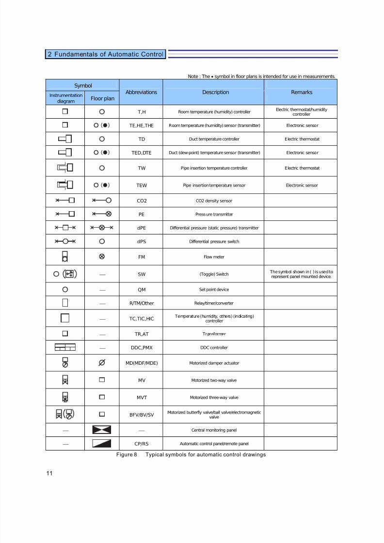
Figure 8 shows a table of typical symbols, Figure 9shows the legends used in instrumentationdiagrams and Figure 10 gives an explanation usingan instrumentation example of an air handling unitcontrol.
2.4 BMS & Automatic Control Design General
7/23/2019 BMS Design Guide
http://slidepdf.com/reader/full/bms-design-guide 13/90
11
2 Fundamentals of Automatic Control
Note : The • symbol in floor plans is intended for use in measurements.
Symbol
Instrumentationdiagram
Floor plan
T,H Room temperature (humidity) controllerElectric thermostat/humidity
controller
TE,HE,THE Room temperature (humidity) sensor (transmitter) Electronic sensor
TD Duct temperature controller Electric thermostat
TED,DTE Duct (dew-point) temperature sensor (transmitter) Electronic sensor
TW Pipe insertion temperature controller Electric thermostat
TEW Pipe insertion temperature sensor Electronic sensor
CO2 CO2 density sensor
PE Pressure transmitter
dPE Differential pressure (static pressure) transmitter
dPS Differential pressure switch
FM Flow meter
⎯ SW (Toggle) Switch The symbol shown in ( ) is used torepresent panel mounted device.
⎯ QM Set point device
⎯ R/TM/Other Relay/timer/converter
⎯ TC,TIC,HIC Temperature (humidity, others) (indicating)
controller
⎯ TR,AT Transformer
⎯ DDC,PMX DDC controller
MD(MDF/MDE) Motorized damper actuator
MV Motorized two-way valve
MVT Motorized three-way valve
BFV/BV/SVMotorized butterfly valve/ball valve/electromagnetic
valve
⎯ ⎯ Central monitoring panel
⎯ CP/RS Automatic control panel/remote panel
Figure 8 Typical symbols for automatic control drawings
Description RemarksAbbreviations
7/23/2019 BMS Design Guide
http://slidepdf.com/reader/full/bms-design-guide 14/90
12
2 Fundamentals of Automatic Control
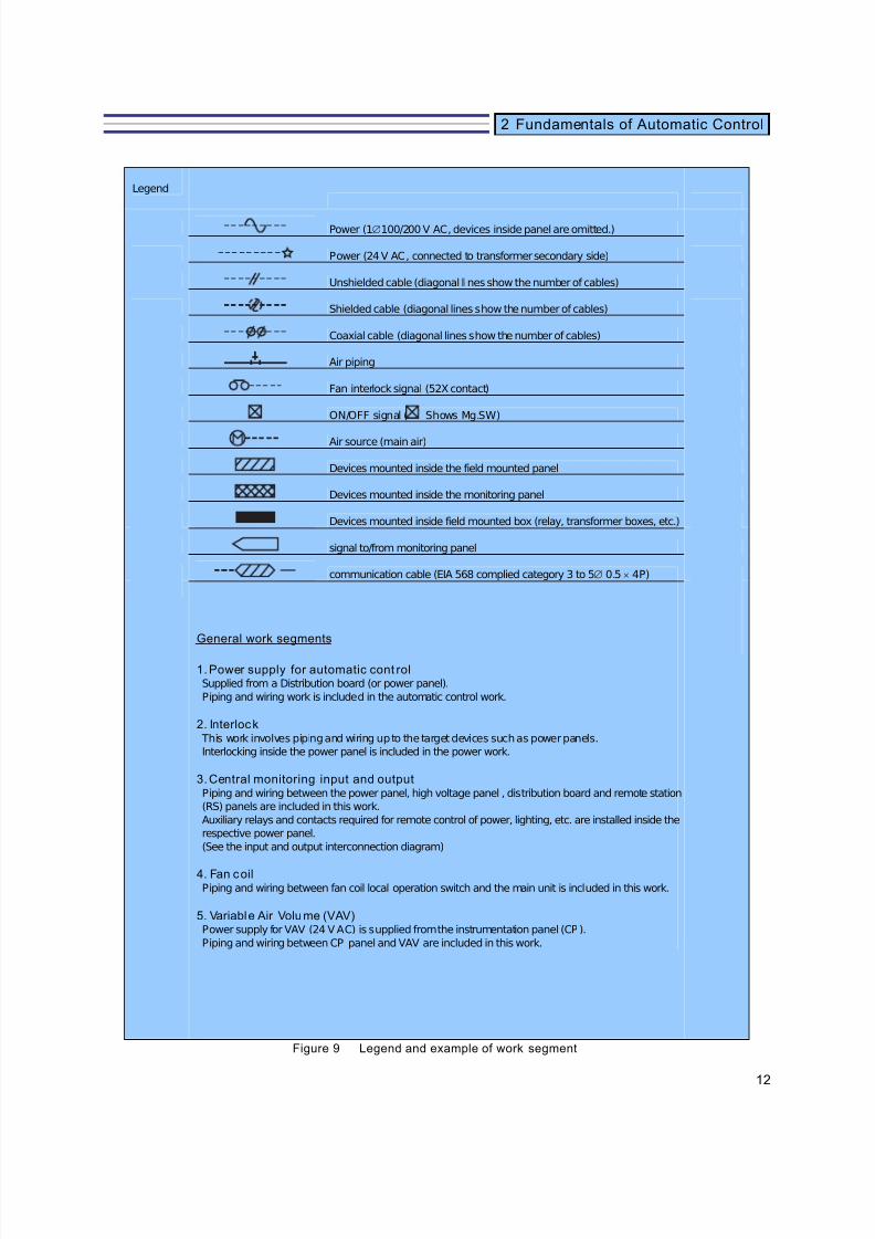
Legend
Power (1∅100/200 V AC, devices inside panel are omitted.)
Power (24 V AC, connected to transformer secondary side)
Unshielded cable (diagonal lines show the number of cables)
Shielded cable (diagonal lines show the number of cables)
Coaxial cable (diagonal lines show the number of cables)
Air piping
Fan interlock signal (52X contact)
ON/OFF signal ( Shows Mg.SW)
Air source (main air)
Devices mounted inside the field mounted panel
Devices mounted inside the monitoring panel
Devices mounted inside field mounted box (relay, transformer boxes, etc.)
signal to/from monitoring panel
communication cable (EIA 568 complied category 3 to 5∅ 0.5 × 4P)
General work segments
1. Power supply for automatic cont rolSupplied from a Distribution board (or power panel).
Piping and wiring work is included in the automatic control work.
2. Interlock This work involves piping and wiring up to the target devices such as power panels.
Interlocking inside the power panel is included in the power work.
3. Central monitoring input and outputPiping and wiring between the power panel, high voltage panel , distribution board and remote station
(RS) panels are included in this work.
Auxiliary relays and contacts required for remote control of power, lighting, etc. are installed inside the
respective power panel.
(See the input and output interconnection diagram)
4. Fan coilPiping and wiring between fan coil local operation switch and the main unit is included in this work.
5. Variable Air Volume (VAV)Power supply for VAV (24 V AC) is supplied from the instrumentation panel (CP ).
Piping and wiring between CP panel and VAV are included in this work.
Figure 9 Legend and example of work segment
7/23/2019 BMS Design Guide
http://slidepdf.com/reader/full/bms-design-guide 15/90
13
2 Fundamentals of Automatic Control
1
DO DI AO AI
I/FCOM DDC
C
C
MV1
C
H
FAN
MV1
R
THEdPS
R.A
2
1
S.A
O.A
TD
BAVMV2
MDF
1
2
TR
AT
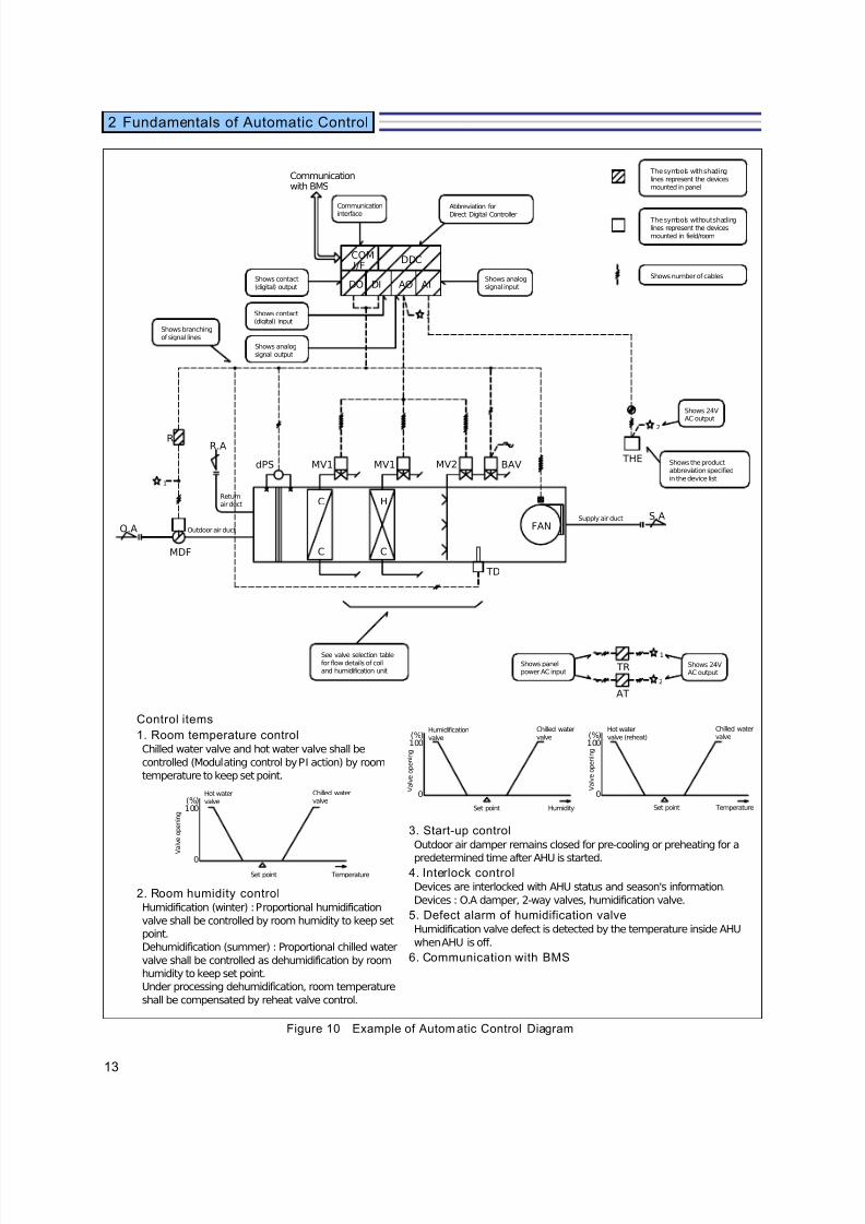
Control items
1. Room temperature controlChilled water valve and hot water valve shall be
controlled (Modulating control by PI action) by room
temperature to keep set point.
100
0
(%)
2. Room humidity controlHumidification (winter) : Proportional humidification
valve shall be controlled by room humidity to keep set
point.
Dehumidification (summer) : Proportional chilled water
valve shall be controlled as dehumidification by room
humidity to keep set point.
Under processing dehumidification, room temperature
shall be compensated by reheat valve control.
(%)100
0
100
0
(%)
3. Start-up controlOutdoor air damper remains closed for pre-cooling or preheating for a
predetermined time after AHU is started.4. Interlock controlDevices are interlocked with AHU status and season's information.
Devices : O.A damper, 2-way valves, humidification valve.
5. Defect alarm of humidification valveHumidification valve defect is detected by the temperature inside AHU
when AHU is off.
6. Communication with BMS
Figure 10 Example of Automatic Control Diagram
Hot watervalve
Chilled watervalve
Set point Temperature
V a l v e o p e n i n g
Humidificationvalve
Chilled watervalve
Set point Humidity
V a l v e o p e n i n g
Hot watervalve (reheat)
Chilled watervalve
Set point Temperature
V a l v e o p e n i n g
Communicationwith BMS
Communication
interface
Abbreviation for
Direct Digital Controller
Shows analogsignal input
Shows contact(digital) output
Shows contact(digital) input
Shows analogsignal output
Shows branchingof signal lines
See valve selection tablefor flow details of coiland humidification unit
Shows panelpower AC input
Shows 24VAC output
Shows the productabbreviation specifiedin the device list
Shows 24VAC output
The symbols with shadinglines represent the devicesmounted in panel
The symbols without shadinglines represent the devicesmounted in field/room
Shows number of cables
Returnair duct
Outdoor air duct
Supply air duct

7/23/2019 BMS Design Guide
http://slidepdf.com/reader/full/bms-design-guide 16/90
14
2 Fundamentals of Automatic Control
Since automatic control plays the important role of being the 'nervous system' of buildings or facilities,sufficient consideration must be paid to the designstage of the buildings.
This section explains the system-wide plan of automatic control made at the planning stage of thebuilding or facilities and examples of procedures of instrumentation and design of individual facilities atthe actual design stage.
Identify the various
characteristics o f the building
Identify the area, use, scale, methods of management and operation, conceptand budget of the building. The importance of control changes depending on thearea or use. For example, some areas may need frost-protection control.
Identify overview of
building facilities
Identify the concept, method, system and number of units of the buildingfacilities.
Determine the conditions
for the plan
Determine the concept, effect of introduction, required quality (requiredaccuracy, etc.) and environmental conditions of the automatic control system.For example, determine which is of primary importance: temperature/humidityconditions, energy conservation, system reliability, etc.
Determine control items
and functions
Determine the control target, items to be controlled, monitored, operated and
over all function for each facility. See Sections 5 and 6.
Select the system
and control method
Select the system-wide configuration and control method to match the requiredfunction. For example, optimum start/stop control of the air handling unit can becarried out at the central monitoring unit and the other AHU controls can beperformed by DDC.
Check consis tency with
facility systems
Check whether the selected control function and control method are consistentwith the facility system. Review of the building or facilities may be necessary forthe required function for automatic control.
Check budgetCheck whether the plan is in line with the budget.
System-wide plan
2.5 Automatic Control System Design Procedure
7/23/2019 BMS Design Guide
http://slidepdf.com/reader/full/bms-design-guide 17/90
15
2 Fundamentals of Automatic Control
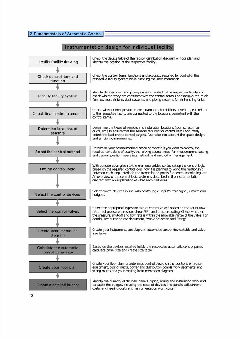
Identify f acility drawing Check the device table of the facility, distribution diagram or floor plan andidentify the position of the respective facility.
Check cont rol item and
function
Check the control items, functions and accuracy required for control of therespective facility system while planning the instrumentation.
Identify facility systemIdentify devices, duct and piping systems related to the respective facility andcheck whether they are consistent with the control items. For example, return airfans, exhaust air fans, duct systems, and piping systems for air handling units.
Check final control elementsCheck whether the operable valves, dampers, humidifiers, inverters, etc. relatedto the respective facility are connected to the locations consistent with the
control items.
Determine locations of
sensors
Determine the types of sensors and installation locations (rooms, return airducts, etc.) to ensure that the sensors required for control items accuratelydetect the load on the control targets. Also take into account the space designand ambient environments.
Select the control methodDetermine your control method based on what it is you want to control, therequired conditions of quality, the driving source, need for measurement, settingand display, position, operating method, and method of management.
Design control logicWith consideration given to the elements added so far, set up the control logicbased on the required control loop, how it is planned to work, the relationshipbetween each loop, interlock, the transmission points for central monitoring, etc.
An overview of the control logic system is described in the instrumentationdiagram with an explanation of what each part does.
Select the control devicesSelect control devices in line with control logic, input/output signal, circuits andbudgets.
Select the control valvesSelect the appropriate type and size of control valves based on the liquid, flowrate, inlet pressure, pressure drop (ÆP), and pressure rating. Check whetherthe pressure, shut-off and flow rate is within the allowable range of the valve. Fordetails, see our separate document, "Valve Selection and Sizing"
Create instrumentation
diagram
Create your instrumentation diagram, automatic control device table and valvesize table.
Calculate the automatic
control panel s ize.
Based on the devices installed inside the respective automatic control panel,calculate panel size and create size table.
Create your floor planCreate your floor plan for automatic control based on the positions of facilityequipment, piping, ducts, power and distribution boards work segments, andwiring routes and your existing instrumentation diagram.
Create a detailed budgetIdentify the quantity of devices, panels, piping, wiring and installation work andcalculate the budget, including the costs of devices and panels, adjustmentcosts, engineering costs and instrumentation work costs.
Instrumentation design for individual facility
7/23/2019 BMS Design Guide
http://slidepdf.com/reader/full/bms-design-guide 18/90
16
2 Fundamentals of Automatic Control
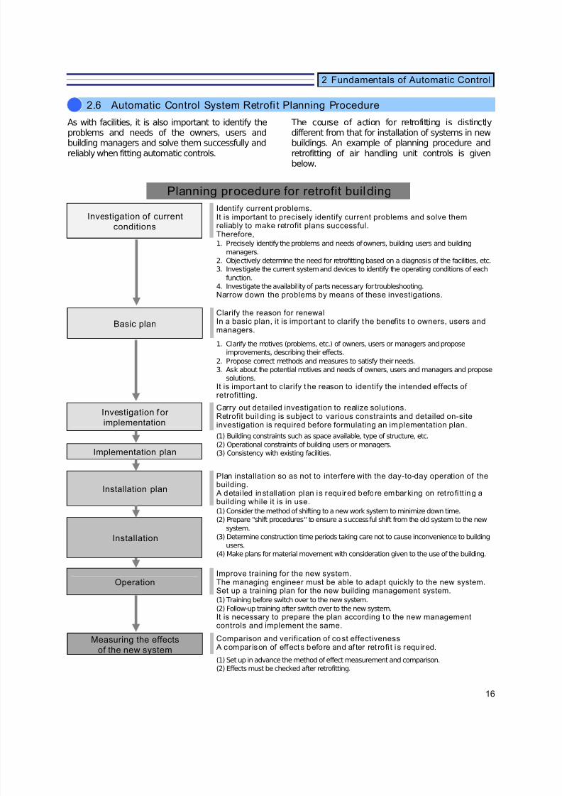
As with facilities, it is also important to identify theproblems and needs of the owners, users andbuilding managers and solve them successfully andreliably when fitting automatic controls.
The course of action for retrofitting is distinctlydifferent from that for installation of systems in newbuildings. An example of planning procedure andretrofitting of air handling unit controls is givenbelow.
Investigation of current
conditions
Identify current problems.It is important to precisely identify current problems and solve themreliably to make retrofit plans successful.Therefore,1. Precisely identify the problems and needs of owners, building users and building
managers.
2. Objectively determine the need for retrofitting based on a diagnosis of the facilities, etc.
3. Investigate the current system and devices to identify the operating conditions of each
function.4. Investigate the availability of parts necessary for troubleshooting. Narrow down the problems by means of these investigations.
Basic plan
Clarify the reason for renewalIn a basic plan, it is important to clarify t he benefits t o owners, users andmanagers.
1. Clarify the motives (problems, etc.) of owners, users or managers and propose
improvements, describing their effects.
2. Propose correct methods and measures to satisfy their needs.
3. Ask about the potential motives and needs of owners, users and managers and propose
solutions.
It is important to clarify t he reason to identify the intended effects of retrofitting.
Investigation for
implementation
Carry out detailed investigation to realize solutions.
Retrofit buil ding is subject to various constraints and detailed on-siteinvestigation is required before formulating an implementation plan.
(1) Building constraints such as space available, type of structure, etc.
(2) Operational constraints of building users or managers.
(3) Consistency with existing facilities.Implementation plan
Installation plan
Plan installation so as not to interfere with the day-to-day operation of thebuilding. A detai led installation plan is required before embarking on retro fi tt ing abuilding while it is in use.
(1) Consider the method of shifting to a new work system to minimize down time.
(2) Prepare "shift procedures" to ensure a successful shift from the old system to the new
system.
(3) Determine construction time periods taking care not to cause inconvenience to building
users.
(4) Make plans for material movement with consideration given to the use of the building.
Installation
OperationImprove training for the new system.The managing engineer must be able to adapt quickly to the new system.Set up a training plan for the new building management system.
(1) Training before switch over to the new system.
(2) Follow-up training after switch over to the new system. It is necessary to prepare the plan according to the new managementcontrols and implement the same.
Measuring the effects
of the new system
Comparison and verification of co st effectiveness A comparison of effects before and af ter ret rofi t i s required.
(1) Set up in advance the method of effect measurement and comparison.
(2) Effects must be checked after retrofitting.
Planning procedure for retrofit building
2.6 Automatic Control System Retrofi t Planning Procedure
7/23/2019 BMS Design Guide
http://slidepdf.com/reader/full/bms-design-guide 19/90
17
2 Fundamentals of Automatic Control
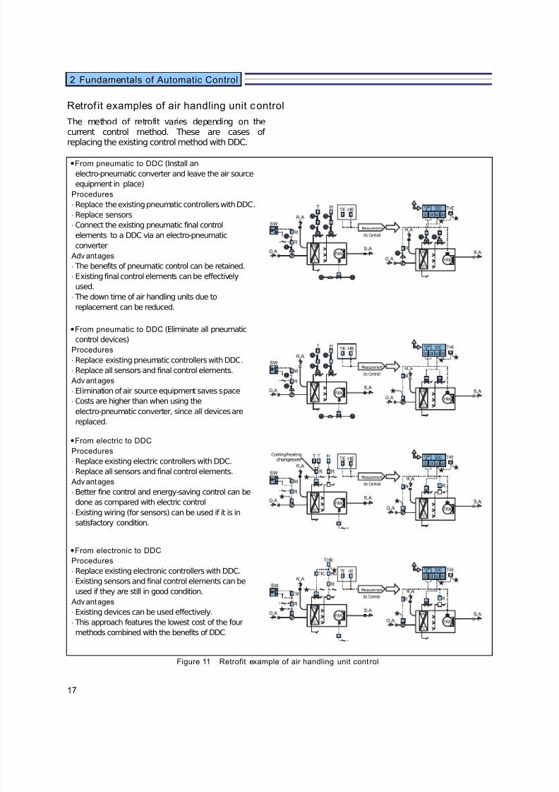
Retrof it examples of air handling unit control
The method of retrofit varies depending on thecurrent control method. These are cases of replacing the existing control method with DDC.
•From pneumatic to DDC (Install an
electro-pneumatic converter and leave the air source
equipment in place)
Procedures
⋅ Replace the existing pneumatic controllers with DDC.
⋅ Replace sensors
⋅ Connect the existing pneumatic final control
elements to a DDC via an electro-pneumatic
converter
Advantages
⋅ The benefits of pneumatic control can be retained.
⋅ Existing final control elements can be effectivelyused.
⋅ The down time of air handling units due to
replacement can be reduced.
•From pneumatic to DDC (Eliminate all pneumatic
control devices)
Procedures
⋅ Replace existing pneumatic controllers with DDC.
⋅ Replace all sensors and final control elements.
Advantages
⋅ Elimination of air source equipment saves space
⋅ Costs are higher than when using the
electro-pneumatic converter, since all devices are
replaced.
•From electric to DDC
Procedures
⋅ Replace existing electric controllers with DDC.
⋅ Replace all sensors and final control elements.
Advantages
⋅ Better fine control and energy-saving control can be
done as compared with electric control
⋅ Existing wiring (for sensors) can be used if it is in
satisfactory condition.
•From electronic to DDC
Procedures
⋅ Replace existing electronic controllers with DDC.
⋅ Existing sensors and final control elements can be
used if they are still in good condition.
Advantages
⋅ Existing devices can be used effectively.
⋅ This approach features the lowest cost of the four
methods combined with the benefits of DDC.
Figure 11 Retrofit example of air handling unit cont rol
Measurement
(to Central)
Measurement
(to Central)
Measurement
(to Central)
Measurement
(to Central)
Cooling/heatingchangeover
7/23/2019 BMS Design Guide
http://slidepdf.com/reader/full/bms-design-guide 20/90
18
3. Automatic Control Devices
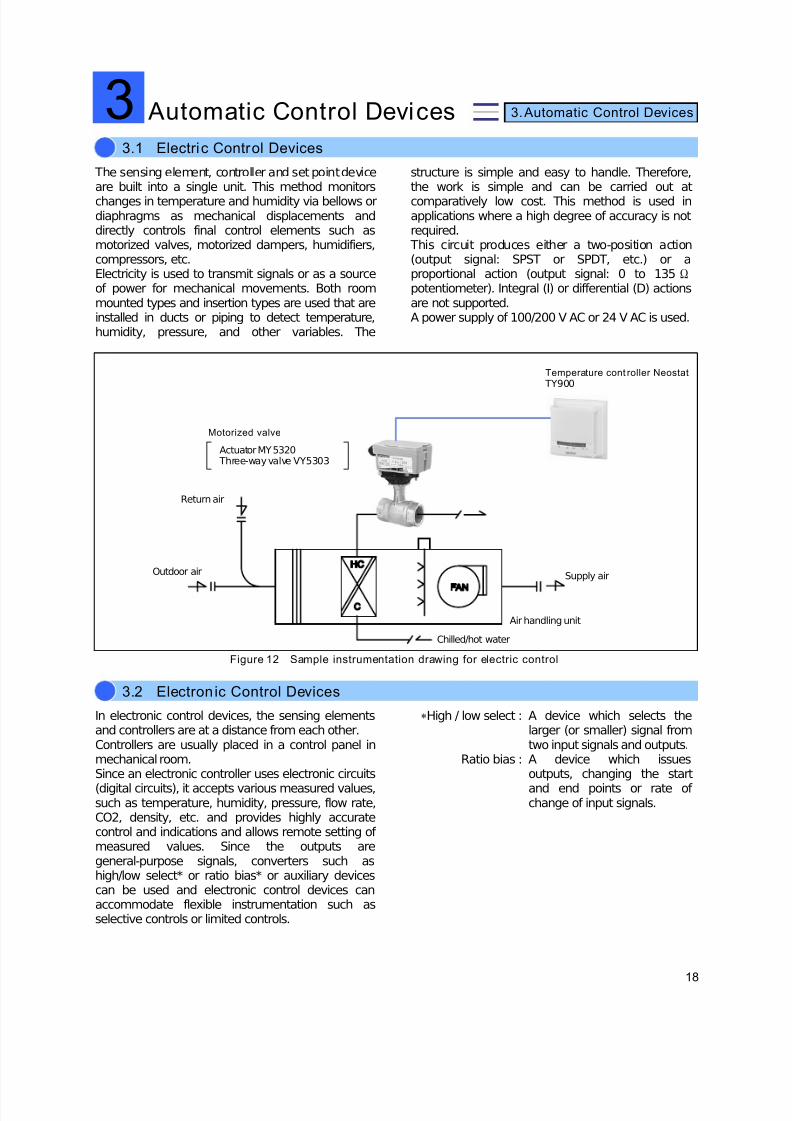
The sensing element, controller and set point deviceare built into a single unit. This method monitorschanges in temperature and humidity via bellows ordiaphragms as mechanical displacements anddirectly controls final control elements such asmotorized valves, motorized dampers, humidifiers,compressors, etc.Electricity is used to transmit signals or as a sourceof power for mechanical movements. Both roommounted types and insertion types are used that areinstalled in ducts or piping to detect temperature,humidity, pressure, and other variables. The
structure is simple and easy to handle. Therefore,the work is simple and can be carried out atcomparatively low cost. This method is used inapplications where a high degree of accuracy is notrequired. This circuit produces either a two-position action(output signal: SPST or SPDT, etc.) or aproportional action (output signal: 0 to 135Ωpotentiometer). Integral (I) or differential (D) actionsare not supported.A power supply of 100/200 V AC or 24 V AC is used.
Figure 12 Sample instrumentation drawing for electric control
In electronic control devices, the sensing elementsand controllers are at a distance from each other.Controllers are usually placed in a control panel inmechanical room.Since an electronic controller uses electronic circuits
(digital circuits), it accepts various measured values,such as temperature, humidity, pressure, flow rate,CO2, density, etc. and provides highly accuratecontrol and indications and allows remote setting of measured values. Since the outputs aregeneral-purpose signals, converters such ashigh/low select* or ratio bias* or auxiliary devicescan be used and electronic control devices canaccommodate flexible instrumentation such asselective controls or limited controls.
∗High / low select :
Ratio bias :
A device which selects thelarger (or smaller) signal fromtwo input signals and outputs.A device which issuesoutputs, changing the start
and end points or rate of change of input signals.
3.1 Electric Control Devices
Automatic Control Devices3
3.2 Electron ic Control Devices
Motorized valve
Actuator MY5320 Three-way valve VY5303
Temperature cont roller Neostat TY900
Supply air
Air handling unit
Chilled/hot water
Outdoor air
Return air
7/23/2019 BMS Design Guide
http://slidepdf.com/reader/full/bms-design-guide 21/90
19
3. Automatic Control Devices
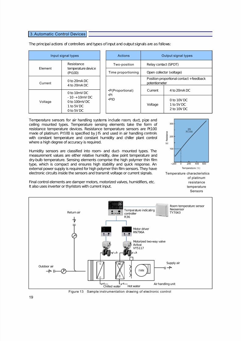
The principal actions of controllers and types of input and output signals are as follows:
Input signal types Actions Output signal types
Element
Resistance
temperature device
(Pt100)
Two-position Relay contact (SPDT)
Time proportioning Open collector (voltage)
Current0 to 20mA DC
4 to 20mA DC
•P(Proportional)
•PI
•PID
Position proportional contact +feedback
potentiometer
Current 4 to 20mA DC
Voltage
0 to 10mV DC
- 10 -+10mV DC
0 to 100mV DC
1 to 5V DC
0 to 5V DC
Voltage
0 to 10V DC
1 to 5V DC
2 to 10V DC
Temperature sensors for air handling systems include room, duct, pipe andceiling mounted types. Temperature sensing elements take the form of resistance temperature devices. Resistance temperature sensors are Pt100made of platinum. Pt100 is specified by J IS and used in air handling controlswith constant temperature and constant humidity and chiller plant controlwhere a high degree of accuracy is required.
Humidity sensors are classified into room- and duct- mounted types. Themeasurement values are either relative humidity, dew point temperature anddry-bulb temperature. Sensing elements comprise the high polymer thin filmtype, which is compact and ensures high stability and quick response. Anexternal power supply is required for high polymer thin film sensors. They haveelectronic circuits inside the sensors and transmit voltage or current signals.
Final control elements are damper motors, motorized valves, humidifiers, etc.It also uses inverter or thyristors with current input.
Temperature characteristics
of platinumresistance
temperature
Sensors
Figure 13 Sample instrumentation drawing of electronic control
Room temperature sensorNeosensor
TY7043 Temperature indicatingcontrollerR36
Motor driverRN796A
Motorized two-way valveActivalVY5117
Return air
Outdoor airSupply air
Air handling unitHot waterChilled water
7/23/2019 BMS Design Guide
http://slidepdf.com/reader/full/bms-design-guide 22/90
20
3. Automatic Control Devices
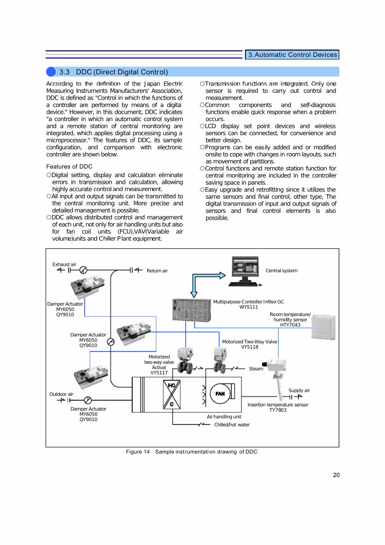
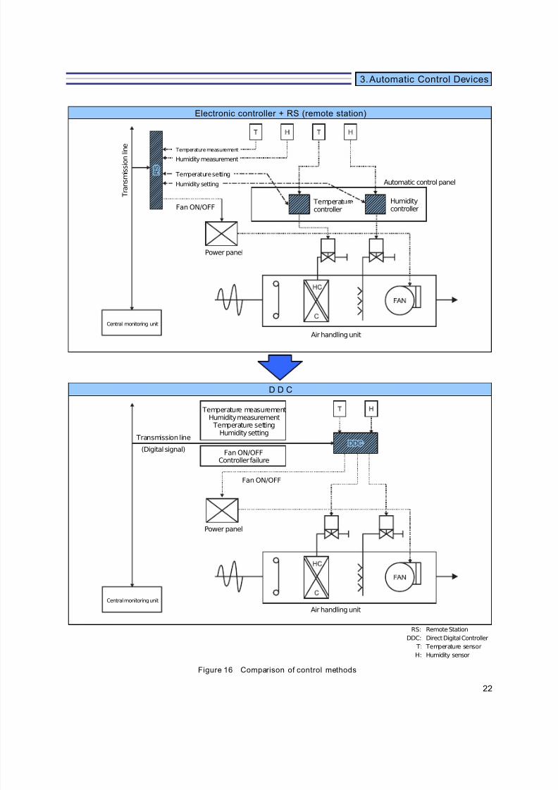
According to the definition of the Japan ElectricMeasuring Instruments Manufacturers' Association,DDC is defined as "Control in which the functions of a controller are performed by means of a digitaldevice." However, in this document, DDC indicates"a controller in which an automatic control systemand a remote station of central monitoring areintegrated, which applies digital processing using amicroprocessor." The features of DDC, its sampleconfiguration, and comparison with electroniccontroller are shown below.
Features of DDC
{Digital setting, display and calculation eliminateerrors in transmission and calculation, allowing
highly accurate control and measurement.{All input and output signals can be transmitted to
the central monitoring unit. More precise anddetailed management is possible.
{DDC allows distributed control and managementof each unit, not only for air handling units but alsofor fan coil units (FCU),VAV(Variable airvolume)units and Chiller Plant equipment.
{ Transmission functions are integrated. Only onesensor is required to carry out control andmeasurement.
{Common components and self-diagnosisfunctions enable quick response when a problemoccurs.
{LCD display set point devices and wirelesssensors can be connected, for convenience andbetter design.
{Programs can be easily added and or modifiedonsite to cope with changes in room layouts, suchas movement of partitions.
{Control functions and remote station function forcentral monitoring are included in the controllersaving space in panels.
{Easy upgrade and retrofitting since it utilizes thesame sensors and final control, other type, Thedigital transmission of input and output signals of sensors and final control elements is alsopossible.
Figure 14 Sample inst rumentation drawing of DDC
3.3 DDC (Direct Digital Control)
Multipurpose Controller Infilex GCWY5111
Central system
Room temperature/humidity sensor
HTY7043
Motorized Two-Way ValveVY5118
Steam
Supply air
Insertion temperature sensor TY7803
Air handling unit
Chilled/hot water
Damper ActuatorMY6050QY9010
Outdoor air
Damper ActuatorMY6050QY9010
Damper ActuatorMY6050QY9010
Exhaust air
Motorizedtwo-way valve
ActivalVY5117
Return air

7/23/2019 BMS Design Guide
http://slidepdf.com/reader/full/bms-design-guide 23/90
21
3. Automatic Control Devices
Figure 15 Example of dist ributed DDC contr oller conf iguration
A
H U r e t u r n a i r f a n
Central monitoring unit
To other DDCcontrollers(peer communication)
Building Management Systemsavic-net series
⋅Call point⋅ON/OFF, setting, status, alarm⋅Real time/totalized data⋅Program data
DDC controller
Fan coil unit
Input interface
Control calculation unit
Output interface
Setting device for engineering
User terminal
A H U s u p p l y a i r f a n
D a m p e
H u m i d i f i e r
I n v e r t e
D a m p e
V a l v e
F i l t e r d i f f e r e n t i a l p r e s s u r e
A H U r e t u r n a i r f a n
A H U s u p p l y a i r f a n
C O 2 d e n s i t y s e n s o r
T e m p e r a t u r e / h u m i d i t y s e n s o
T e m p e r a t u r e / h u m i d i t y s e n s o
C o m m u n i c a t i o n f i l e
D a t a s e t t i n g f i l e
D i g i t a l t r a n s m i s s i o n l i n e
7/23/2019 BMS Design Guide
http://slidepdf.com/reader/full/bms-design-guide 24/90
22
3. Automatic Control Devices
Electronic controller + RS (remote station)
D D C
RS:
DDC:
T:
H:
Remote Station
Direct Digital Controller
Temperature sensor
Humidity sensor
Figure 16 Comparison of control methods
Temperature measurement
Humidity measurement Temperature setting
Humidity setting
Fan ON/OFFController failure
Transmission line
(Digital signal)
Fan ON/OFF
Power panel
Air handling unit
Central monitoring unit
Automatic control panel
Humiditycontroller
Temperaturecontroller
Air handling unit
Power panel
Central monitoring unit
Temperature measurement
Humidity measurement
Temperature setting
Humidity setting
T r a n s m i s s i o n l i n e
Fan ON/OFF
7/23/2019 BMS Design Guide
http://slidepdf.com/reader/full/bms-design-guide 25/90
23
3. Automatic Control Devices
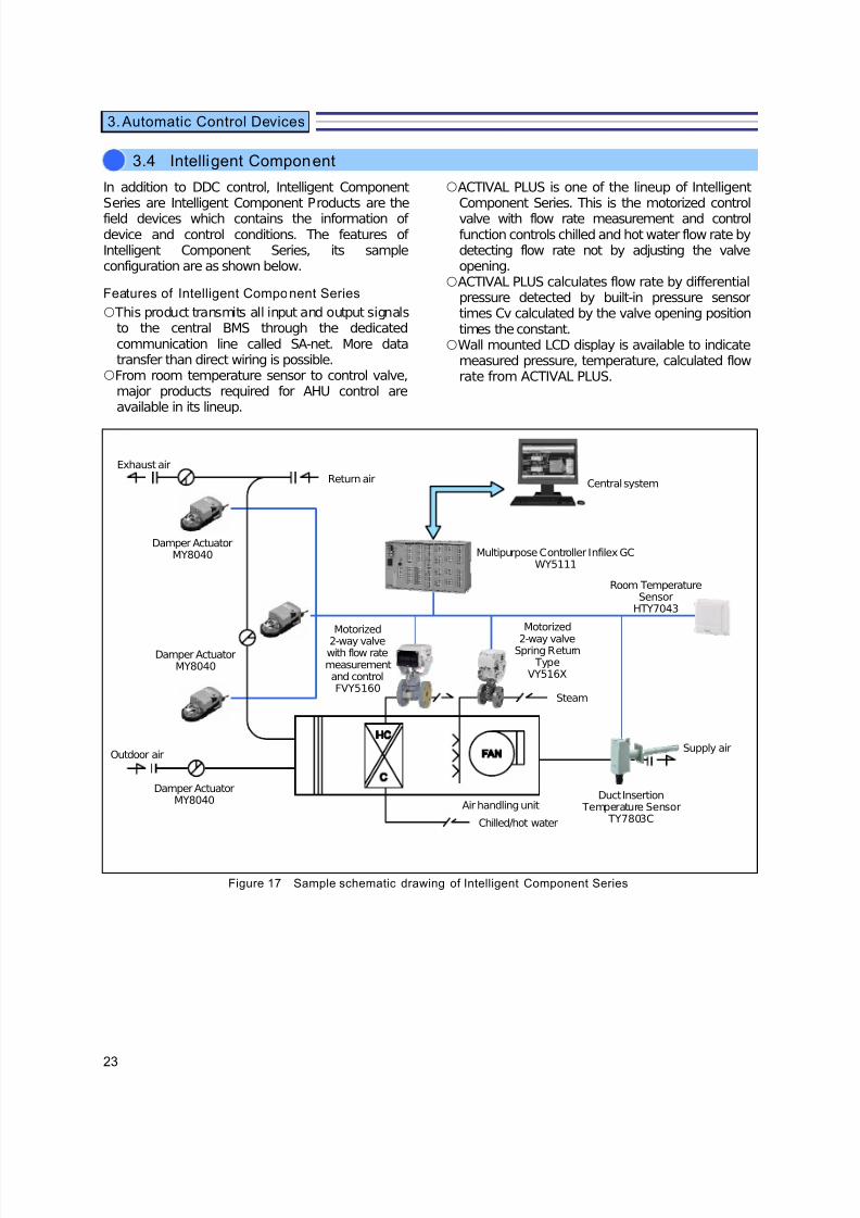
In addition to DDC control, Intelligent ComponentSeries are Intelligent Component Products are thefield devices which contains the information of device and control conditions. The features of Intelligent Component Series, its sampleconfiguration are as shown below.
Features of Intelligent Component Series
{ This product transmits all input and output signalsto the central BMS through the dedicatedcommunication line called SA-net. More datatransfer than direct wiring is possible.
{From room temperature sensor to control valve,major products required for AHU control areavailable in its lineup.
{ACTIVAL PLUS is one of the lineup of IntelligentComponent Series. This is the motorized controlvalve with flow rate measurement and controlfunction controls chilled and hot water flow rate bydetecting flow rate not by adjusting the valveopening.
{ACTIVAL PLUS calculates flow rate by differentialpressure detected by built-in pressure sensortimes Cv calculated by the valve opening positiontimes the constant.
{Wall mounted LCD display is available to indicatemeasured pressure, temperature, calculated flowrate from ACTIVAL PLUS.
Figure 17 Sample schematic drawing of Intelligent Component Series
3.4 Intelligent Component
Multipurpose Controller Infilex GCWY5111
Central system
Room TemperatureSensor
HTY7043
Motorized
2-way valveSpring Return
TypeVY516X
Steam
Supply air
Duct Insertion Temperature Sensor
TY7803C
Air handling unit
Chilled/hot water
Damper ActuatorMY8040
Outdoor air
Damper ActuatorMY8040
Damper ActuatorMY8040
Exhaust air
Motorized
2-way valvewith flow ratemeasurementand controlFVY5160
Return air

7/23/2019 BMS Design Guide
http://slidepdf.com/reader/full/bms-design-guide 26/90

7/23/2019 BMS Design Guide
http://slidepdf.com/reader/full/bms-design-guide 27/90
25
Air handling is divided into three systems: outdoorair processing, room interiors,or room perimeters, depending on the load each airhandling unit is processing.
Appropriate AHUs are adopted for each system. There are various ways of classifying the AHUs. The following ways are amenable to automaticcontrol.
(1) Outdoor AHU
In this AHU, only outdoor air is drawn in and processed
without any return air from the system.
Total heat exchangers are added in some cases. This unit is
suitable with the combination of fan coil units, for individual
rooms of hotels or hospitals, and AHUs on each floor in office
buildings. In this type, controls are performed based on
supply air temperature and dew point temperature.
However, it is also possible to bypass all heat converters for
outdoor air cooling depending on the season.
(2) Constant air volume (CAV) AHU
This method processes room load (return air) and outdoor air
load (outdoor air), or room load only, and distributes constant
air volume via ducts. A cooling/heating coil or combination of
a cooling coil and a heating coil are used. This method
controls zones with fairly constant load characteristics and is
used extensively, from large spaces such as theaters or
shopping centers, interiors of small to medium sized
buildings, to zoned air handling in large buildings and units
on each floor. The CAV AHU performs temperature and
humidity control of rooms by controlling the amount of return
air supplied back to the room. It also performs room
temperature and CO2 density control by monitoring the
outdoor air load and controlling the intake of outdoor air.
(3) Variable air volume (VAV) AHU
based on This method further divides zones with similar load
tendency, controls these zones using individual VAV units,
and reduces the total air volume of AHU using inverters, etc.
accordingly. Compared with CAV AHUs, VAV AHUs can
control the zones better with respect to the load on each
small zone and thus enable energy conservation. Thismethod is suited for medium-to large-sized office buildings
with wide air handling areas which place importance on
running costs. VAV AHUs control each VAV room
temperature and control supply air temperature and fan air
volume accordingly.
They also controls outdoor air and CO2 condensation in the
same way as for CAV AHUs.
(4) Packaged air condit ioner
This is a room unit incorporating a compressor. There are
two types: a cooling compressor + electric heater type andheat pump type. Also there are water source types and
multi-type units which need to be installed in multiple rooms.
This method is mainly used for air handling of spaces with
load characteristics and operating times that differ from other
spaces, from computer rooms to stores or small-sized office
buildings. In packaged air conditioners, ON/OFF control to
determine the number of operating units of compressors in
response to room temperature, etc. are carried out.
(5) Fan coi l un it (FCU)
A compact air conditioner which incorporates a fan, a coil,
and a filter, etc.
Generally, it does not take in outdoor air or perform
humidifying, but simply carries out air circulation. There are
floor standing, ceiling-mounted and cassette types.
This method is suited for individual rooms in hotels or
hospitals or perimeters in office buildings.
The FCU controls room or return air temperature bycontrolling valves individually or in groups (for zones). They
can be used to optimize load sharing with air handling units
in interior or outdoor air processing air handling units as well
as to carry out energy-saving control.
4.1 AHU Systems
HVAC System generals
Supply air
To indoor AHUOutdoor air
Exhaust air
Outdoor air
Exhaust air
Outdoor air
Supply air
Return air
Outdoor air
4
7/23/2019 BMS Design Guide
http://slidepdf.com/reader/full/bms-design-guide 28/90
26
4. HVAC System generals
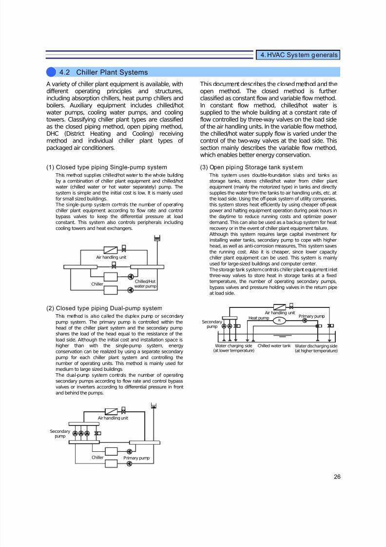
A variety of chiller plant equipment is available, withdifferent operating principles and structures,including absorption chillers, heat pump chillers andboilers. Auxiliary equipment includes chilled/hotwater pumps, cooling water pumps, and coolingtowers. Classifying chiller plant types are classifiedas the closed piping method, open piping method,DHC (District Heating and Cooling) receivingmethod and individual chiller plant types of packaged air conditioners.
This document describes the closed method and theopen method. The closed method is furtherclassified as constant flow and variable flow method.In constant flow method, chilled/hot water issupplied to the whole building at a constant rate of flow controlled by three-way valves on the load sideof the air handling units. In the variable flow method,the chilled/hot water supply flow is varied under thecontrol of the two-way valves at the load side. Thissection mainly describes the variable flow method,which enables better energy conservation.
(1) Closed type piping Single-pump system
This method supplies chilled/hot water to the whole building
by a combination of chiller plant equipment and chilled/hot
water (chilled water or hot water separately) pump. The
system is simple and the initial cost is low. It is mainly usedfor small sized buildings.
The single-pump system controls the number of operating
chiller plant equipment according to flow rate and control
bypass valves to keep the differential pressure at load
constant. This system also controls peripherals including
cooling towers and heat exchangers.
(2) Closed type piping Dual-pump system
This method is also called the duplex pump or secondary
pump system. The primary pump is controlled within the
head of the chiller plant system and the secondary pump
shares the load of the head equal to the resistance of the
load side. Although the initial cost and installation space is
higher than with the single-pump system, energy
conservation can be realized by using a separate secondary
pump for each chiller plant system and controlling the
number of operating units. This method is mainly used for
medium to large sized buildings.
The dual-pump system controls the number of operating
secondary pumps according to flow rate and control bypassvalves or inverters according to differential pressure in front
and behind the pumps.
(3) Open piping Storage tank system
This system uses double-foundation slabs and tanks as
storage tanks, stores chilled/hot water from chiller plant
equipment (mainly the motorized type) in tanks and directly
supplies the water from the tanks to air handling units, etc. atthe load side. Using the off-peak system of utility companies,
this system stores heat efficiently by using cheaper off-peak
power and halting equipment operation during peak hours in
the daytime to reduce running costs and optimize power
demand. This can also be used as a backup system for heat
recovery or in the event of chiller plant equipment failure.
Although this system requires large capital investment for
installing water tanks, secondary pump to cope with higher
head, as well as anti-corrosion measures, This system saves
the running cost. Also it is cheaper, since lower capacity
chiller plant equipment can be used. This system is mainly
used for large-sized buildings and computer center.
The storage tank system controls chiller plant equipment inlet
three-way valves to store heat in storage tanks at a fixed
temperature, the number of operating secondary pumps,
bypass valves and pressure holding valves in the return pipeat load side.
4.2 Chiller Plant Systems
Chiller
Air handling unit
Chilled/Hot
water pump
Secondarypump
Air handling unit
Chiller Primary pump
Primary pumpHeat pump
Air handling unit
Secondarypump
Water charging side(at lower temperature)
Chilled water tank Water discharging side(at higher temperature)
7/23/2019 BMS Design Guide
http://slidepdf.com/reader/full/bms-design-guide 29/90
27
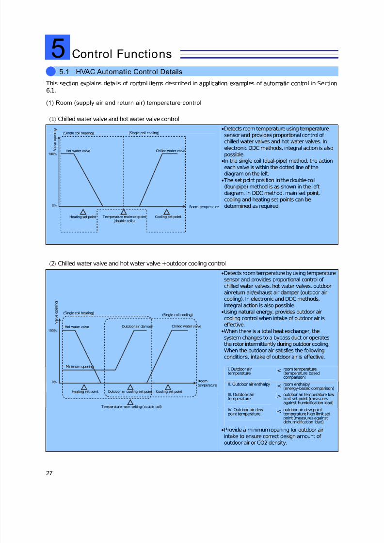
This section explains details of control items described in application examples of automatic control in Section6.1.
(1) Room (supply air and return air) temperature control
⟨1⟩ Chilled water valve and hot water valve control
•Detects room temperature using temperaturesensor and provides proportional control of chilled water valves and hot water valves. In
electronic DDC methods, integral action is alsopossible.•In the single coil (dual-pipe) method, the actioneach valve is within the dotted line of thediagram on the left.
• The set point position in the double-coil(four-pipe) method is as shown in the leftdiagram. In DDC method, main set point,cooling and heating set points can be
determined as required.
⟨2⟩ Chilled water valve and hot water valve +outdoor cooling control
•Detects room temperature by using temperaturesensor and provides proportional control of
chilled water valves, hot water valves, outdoorair/return air/exhaust air damper (outdoor aircooling). In electronic and DDC methods,
integral action is also possible.•Using natural energy, provides outdoor aircooling control when intake of outdoor air iseffective.•When there is a total heat exchanger, thesystem changes to a bypass duct or operatesthe rotor intermittently during outdoor cooling.When the outdoor air satisfies the followingconditions, intake of outdoor air is effective.
i. Outdoor airtemperature
< room temperature(temperature basedcomparison)
II. Outdoor air enthalpy < room enthalpy(energy-based comparison)
III. Outdoor airtemperature
> outdoor air temperature lowlimit set point (measuresagainst humidification load)
IV. Outdoor air dewpoint temperature
< outdoor air dew pointtemperature high limit setpoint (measures againstdehumidification load)
•Provide a minimum opening for outdoor airintake to ensure correct design amount of outdoor air or CO2 density.
5.1 HVAC Automatic Control Details
Control Functions
(Single coil cooling)
Hot water valve
(Single coil heating)
Outdoor air damper
Minimum opening
Chilled water valve
Room temperature
Cooling set pointHeating set point Outdoor air cooling set point
Temperature main setting (double coil)
V a l v e o p e n i n g
Cooling set point
(Single coil heating) (Single coil cooling)
Chilled water valve
Room temperature
Hot water valve
Temperature main set point(double coils)
Heating set point
V a l v e o p e n i n g
5

7/23/2019 BMS Design Guide
http://slidepdf.com/reader/full/bms-design-guide 30/90
28
5 Control Functions
Expression of outdoor air intake condition
on a psychrometric chart
The conditions of I to IV in ⟨2⟩ of the previous pageare expressed on a psychrometric chart as shownon the right.
⟨3⟩ Temperature control of heat pump package
•Performs ON/OFF control of compressorsaccording to room temperature.
(2) Room (return air) humidity control
⟨1⟩ Humidifier control
•Provides ON/OFF control of humidifier accordingto room humidity.
•Mainly used for vaporizing humidifying, waterhumidification, ultrasonic humidification and pan
humidification.
⟨2⟩ Control of humidifying valve and chilled water valve
•Provides PI control to humidifying and chilledwater valves according to room (return air)
humidity to provide humidifying anddehumidifying reheat control.•For electric control or humidifying only system,the valve action is within the dotted line•For dehumidification, when humidity increases,the chilled water valve opens. As a result, theheating coil (hot water coil) reheats tocompensate for the decrease in room (supply air,
return air) temperature.•Proportional control of humidification achieved byapplying steam humidification or steamgenerator
•In steam humidification applications, the supplyair dew point temperature can be used as thecontrol.
Dry bulb temperature
Outdoor air intake effective area
Roomenvironment
A b s o l u t e h u m i d i t y
Heating set point
S t a t u s
Heating/cooling changeover isdone manually.
Cooling set point
Temperature
CompressorCompressor
Heating Cooling
V a l v e o p e n i n g
Humidifying set point
Humidity set point
Dehumidifying set point
Humidity
Chilled water valveHumidifying valve
Humidity
S t a t u s
Humidifying set point

7/23/2019 BMS Design Guide
http://slidepdf.com/reader/full/bms-design-guide 31/90
29
5 Control Functions
(3) Supply air temperature cascade control
Changes supply air temperature set point tocontrol supply air temperature based on the
control output of room temperature and roomtemperature set point. Due to this, the impact of process lag and disturbances can be reduced.
(4) Supply air temperature limit control
This function controls supply air temperaturewithin high and low limits. This preventsoverheating during heating, temperaturestratification and condensation at outlet duringcooling.
(5) Supply air temperature set point optimization
control
In a variable air volume air handling unit,calculates optimum supply air temperature setpoint based on air volume of VAV and roomtemperature to prevent insufficient ventilationand heat output.
(6) Supply air vo lume cont rol by VAV air volume
Adds up air volume of all VAVs and CAVs tooutput the speed of rotation in line with the fanspeed characteristics of the AHU. Controls thefan speed in stages based on VAV opening. Setsminimum fan speed to ensure minimum outdoorair volume for ventilation.
(7) Warming up controlDuring warming up of air handling unit(pre-cooling/preheating), the following controlsare achieved. The time between the start of AHUtill start of occupancy is called as warming upperiod. The length of the warming up period isdetermined by calculation in the centralmonitoring unit or delay timer.
[1] Outdoor air intake disabled
(outdoor air/exhaust air/outdoor air
bypass/exhaust air bypass damper: fully
closed, return air damper: fully open)
To reduce outdoor air load, the outdoor air intake isdisabled. This reduces warming up time andreduces power consumption by the fans. However,
when outdoor air cooling is effective, outdoor airintake is performed.
[2] A humidification disabled
During warming up, there is a change in
temperature, room relative humidity tends to beunstable, and the control does not stabilize. Inorder to prevent condensation in the supply air
duct, humidification is disabled by interlock(Humidifier OFF or humidifying valve fully closed).
[3] Total heat exchanger off
Turn off total heat exchanger because outdoor airis not taken in.
(8) Interlock control while AHU fan is off
[1] Disable humidification
[2] Chilled/hot w ater valve fully c losed
[3] Outdoor air/exhaust air/outdoor air
bypass/exhaust air bypass damper fully closed
[4] Return air damper fully open
[5] Total heat exchanger off
[6] VAV fully open
(9) Communication w ith central monitoring
system
In case of DDC system, input and output signalsand calculation values can be transmitted to the
controller as required, except the followingtypical items.[1] ON/OFF of fan, status failure monitoring
[2] Filter differential pressure alarm monitoring
[3] Room (return air, supply air) temperature and
humidity measurement
[4] Room temperature and humidity setting
[5] Warming up command
[6] Monitoring of DDC controller failure
(10)Control of chiller plant system
This controls the number of operating pumps orchiller plant equipment for generating andsupplying the heat required by the load AHU.
[1] Number of operating pumps controlIn response to changes in load, it controls the
differential pressure between headers in the singlepump system, and controls the number of operating secondary pumps and bypass valvesaccording to the flow rate in the double-pump
system. Uses PID control of bypass two-wayvalves to maintain output pressure to loadconstant.
[2] Number of operating chiller/hot water
generators contr ol
In dual pump system, it controls number of operating chilled/hot water generators dependingon the load by measuring return header
temperature. This improves response to thechange in required flow rate of secondary side (airhandling units), supply water temperature to thesecondary side, return temperature and flow rate.
7/23/2019 BMS Design Guide
http://slidepdf.com/reader/full/bms-design-guide 32/90
30
5 Control Functions
(1) Power/lighting management, control function
For effective and safe usage of power, itmeasures power, current, power factor tomonitor, control and report power receptionstatus, relay status, occurrence of groundfault/leakage of electricity and operating status of generators.
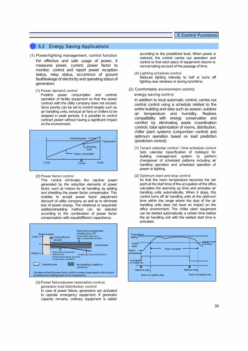
[1] Power demand control
Predicts power consumption and controlsoperation of facility equipment so that the powercontract with the utility company does not exceed.Since priority can be set to control targets such as
air handling units, exhaust air fans or chillers to bestopped in peak periods, it is possible to controlcontract power without having a significant impact
on the environment.
[2] Power factor control
This control eliminates the reactive power
generated by the reduction elements of powerfactor, such as motors for air handling, by addingand shedding the power factor compensator. Thisenables to accept power factor adjustment
discount of utility company as well as to eliminateloss of power energy. The rotational or sequentialaddition/shedding method can be selected
according to the combination of power factorcompensators with equal/different capacitance.
[3] Power failure/power restoration contr ol,
generator load distribution control
In case of power failure, generators are activatedto operate emergency equipment. If generatorcapacity remains, ordinary equipment is added
according to the predefined level. When power isrestored, the control carries out operation and
control so that each piece of equipment returns tonormal taking account of the passage of time.
[4] Lighting schedule control
Reduces lighting intensity to half or turns off lighting near windows or during lunchtime.
(2) Comfortable environment control,
energy-saving control
In addition to local automatic control, carries outcentral control using a schedule related to theentire building and data such as season, outdoorair temperature and humidity. Realizescompatibility with energy conservation and
comfort by eliminating waste (coordinationcontrol), total optimization of rooms, distribution,chiller plant systems (conjunction control) andoptimum operation based on load prediction(prediction control).
[1] Tenant calendar control / time schedule control
Sets calendar (specification of holidays) forbuilding management system to performchangeover of scheduled patterns including air
handling operation and scheduled operation of power or lighting.
[2] Optimum start and stop control
So that the room temperature becomes the set
point at the start time of the occupation of the office,calculates the warming up time and activates airhandling units automatically. When it stops, thiscontrol turns off air handling units at the optimum
time within the range where the stop of the airhandling units does not have an impact on theoffice environment. The chiller plant equipment
can be started automatically a certain time beforethe air handling unit with the earliest start time isactivated.
5.2 Energy Saving Applications
Predicted power
Target power
Sheddinglevel
Power consumption
Current
Temperaturesetting
Start/stop targettemperature
Room occupied
Target
value
Roomtemperature
Operation of air handling unit
Optimum start Optimum stop
Room occupation start Room occupation end
Reactive power
Control effectivelow limit
Power factor compensatorshedding level (TX)
Active power
Target power factor low limit (PFL)
Power factor compensatoradd level (CX)
(If power factor delays up to here,compensators are added.)
Shedding area No shedding or addition iscarried out
Calculate so that the power factor is within a certain range based on the set pointby adding and shedding power factor compensators.
If power factor leads up tohere, compensators are shed.
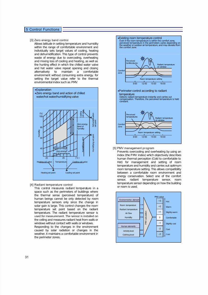
7/23/2019 BMS Design Guide
http://slidepdf.com/reader/full/bms-design-guide 33/90
31
5 Control Functions
[3] Zero energy band control
Allows latitude in setting temperature and humiditywithin the range of comfortable environment and
individually sets target values of cooling, heatingand dehumidification. This type of control prevents
waste of energy due to overcooling, overheatingand mixing loss of cooling and heating, as well asthe hunting effect in which the chilled water valve
and hot water valve repeat opening and closingalternatively to maintain a comfortableenvironment without consuming extra energy. forsetting the target value refer to the thermal
environmental index such as PMV.
•Explanation•Zero energy band and action of chilledwater/hot water/humidifying valve
[4] Radiant temperature control
This control measures radiant temperature in aspace such as the perimeters of buildings where
the thermal sense (perceived temperature) of human beings cannot be only detected by roomtemperature sensors only since the change in
solar gain is large. This control changes the roomtemperature set point based on the radianttemperature. The radiant temperature sensor is
used for measurement. The sensor is installed onthe ceiling and measures radiant heat from walls orwindows without contact with walls or windows.
Responding to the changes in the environmentcaused by solar radiation or changes in theweather, it maintains a comfortable environment inthe perimeter zones.
•Existing room temperature controlEven if the room temperature is within the comfort zone,perceived temperature in the perimeters varies depending onthe weather or outdoor air temperature, and may deviate fromthe comfort zone.
•Perimeter control according to radianttemperatureDetects radiant temperature instantly and carries outcompensation. Therefore, the perceived temperature is heldconstant.
[5] PMV management program
Prevents overcooling and overheating by using an
index (the PMV index) which objectively describeshuman thermal perception (Cold to comfortable toHot) for management and setting of roomtemperature and humidity and carries out optimum
room temperature setting. This allows compatibilitybetween a comfortable room environment andenergy conservation. Select one of the comfortsensor, radiant temperature sensor, room
temperature sensor depending on how the buildingor room is used.
Perceivedtem eratures
Comfortzone
Room temperature setting
Radiant temperatureon window
Zero energyband of temperature
Heating set point Cooling set point
Cooling coil valveHeating coil valve Temperature
Zero energyband of humidity
D e h u m i d i f i c a t i o n
s e t p o i n t
H u m i d i f y i n g s e t p o i n t
H u m i d i t y
C o o l i n g
c o i l v a l v e
H u m i d i f y i n g v a l v e
Room temperature
Environmental element
Radiant temperature
Air flow
Humidity
Hot
Warm
Slightly warm
Comfortable
Slightly cool
Cool
Cold
PMV value
Human elements
Activity level
Clothing level
P M V c a l c u l a t i o n
Perceivedtemperatures
Comfortzone
Room temperature setting
Radiant temperatureon window
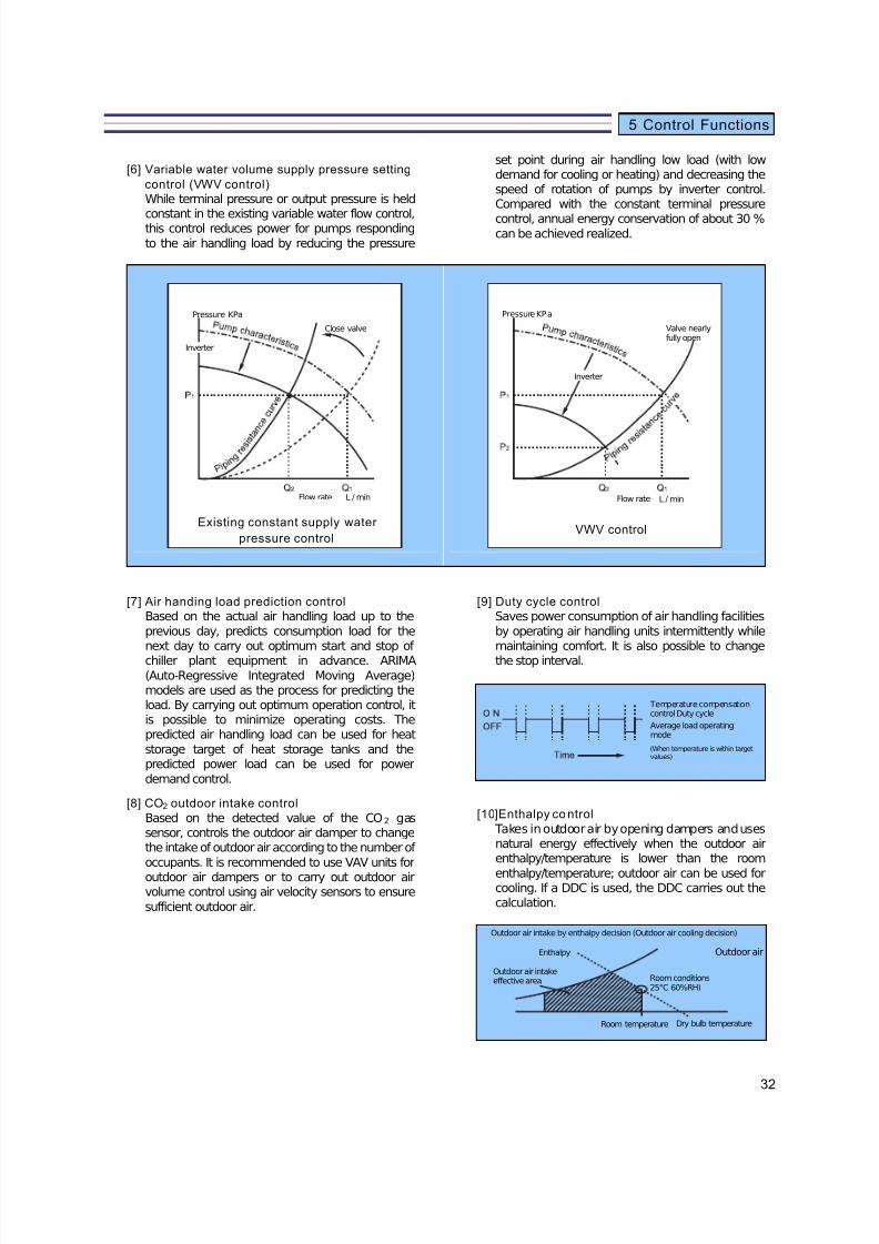
7/23/2019 BMS Design Guide
http://slidepdf.com/reader/full/bms-design-guide 34/90
32
5 Control Functions
[6] Variable water volume supply pressure setting
control (VWV control)
While terminal pressure or output pressure is held
constant in the existing variable water flow control,this control reduces power for pumps responding
to the air handling load by reducing the pressure
set point during air handling low load (with lowdemand for cooling or heating) and decreasing thespeed of rotation of pumps by inverter control.Compared with the constant terminal pressure
control, annual energy conservation of about 30 %can be achieved realized.
[7] Air handing load prediction control
Based on the actual air handling load up to the
previous day, predicts consumption load for thenext day to carry out optimum start and stop of chiller plant equipment in advance. ARIMA
(Auto-Regressive Integrated Moving Average)models are used as the process for predicting theload. By carrying out optimum operation control, itis possible to minimize operating costs. Thepredicted air handling load can be used for heat
storage target of heat storage tanks and thepredicted power load can be used for power
demand control.
[8] CO2 outdoor intake control
Based on the detected value of the CO2 gassensor, controls the outdoor air damper to changethe intake of outdoor air according to the number of
occupants. It is recommended to use VAV units foroutdoor air dampers or to carry out outdoor airvolume control using air velocity sensors to ensure
sufficient outdoor air.
[9] Duty cycle control
Saves power consumption of air handling facilities
by operating air handling units intermittently whilemaintaining comfort. It is also possible to changethe stop interval.
[10]Enthalpy co ntrol
Takes in outdoor air by opening dampers and usesnatural energy effectively when the outdoor airenthalpy/temperature is lower than the room
enthalpy/temperature; outdoor air can be used forcooling. If a DDC is used, the DDC carries out thecalculation.
Pressure KPa
Inverter
Close valve
Flow rate L / min
Existing constant supply water
pressure control
Pressure KPa
Valve nearlyfully open
Inverter
Flow rate L / min
VWV control
Temperature compensationcontrol Duty cycle
Average load operatingmode
(When temperature is within targetvalues)
Outdoor air intake by enthalpy decision (Outdoor air cooling decision)
Enthalpy
Outdoor air intakeeffective area Room conditions
25°C 60%RH)
Outdoor air
Room temperature Dry bulb temperature
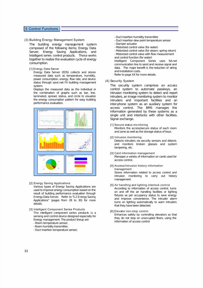
7/23/2019 BMS Design Guide
http://slidepdf.com/reader/full/bms-design-guide 35/90
33
5 Control Functions
(3) Building Energy Management System
The building energy management systemcomposed of the following items; Energy DataServer, Energy Saving Applications, andIntelligent series control products. Those workstogether to realize the evaluation cycle of energyconsumption.
[1] Energy Data Server
Energy Data Server (EDS) collects and storesmeasured data such as temperature, humidity,power consumption, energy, flow rate, and devicestatus through savic-net FX building management
system.Displays the measured data as the individual or
the combination of graphs such as bar, line,laminated, spread, status, and circle to visualize
the energy consumption pattern for easy buildingperformance evaluation.
[2] Energy Saving Applications
Various types of Energy Saving Applications areused to improve energy consumption based on theresult of building performance evaluation throughEnergy Data Server. Refer to “5.2 Energy Saving
Applications” (pages from 28 to 30) for moredetails.
[3] Intelligent Component Series Products
The intelligent component series products is asensing and control device designed especially forEnergy management. The product lineup are- Room temperature sensor,- Room humidity transmitter,
- Duct insertion temperature sensor,
- Duct insertion humidity transmitter- Duct insertion dew point temperature sensor- Damper actuator- Motorized control valve (for water)
- Motorized control valve (for steam; spring return)- Motorized control valve with flow measurementand control function (for water)Intelligent Component Series uses SA-net
communication line to send and receive signal anddata. The major benefit is the reduction of wiringand installation costs.
Refer to page XX for more details.
(4) Security System
The security system comprises an accesscontrol system to automate passkeys, anintrusion monitoring system to detect and reportintruders, an image monitoring system to monitor
intruders and important facilities and aninter-phone system as an auxiliary system foraccess control. The BMS manages theinformation generated by these systems as asingle unit and interlocks with other facilities.Signal exchange.
[1] Secure status mo nitoring
Monitors the access/secure status of each roomand zone as well as the storage status of keys.
[2] Intrusion monitoring
Detects intruders via security sensors and detectsand monitors broken glasses and systemtampering, etc.
[3] Card information management
Manages a variety of information on cards used for
access control.
[4] Access/intrusion history information
management
Stores information related to access control andintrusion monitoring to carry out historymanagement.
[5] Air handling and lighting interlock cont rol
According to information of access control, turnson and off the air handling facilities or lighting
fixtures as per occupancy status to save energyand improve convenience. The intruder alarm
turns on lighting automatically to warn intrudersthat they have been detected.
[6] Elevator non-stop control
Enhances safety by controlling elevators so that
they do not stop on unoccupied floors, using theinformation of access control

7/23/2019 BMS Design Guide
http://slidepdf.com/reader/full/bms-design-guide 36/90
34
5 Control Functions
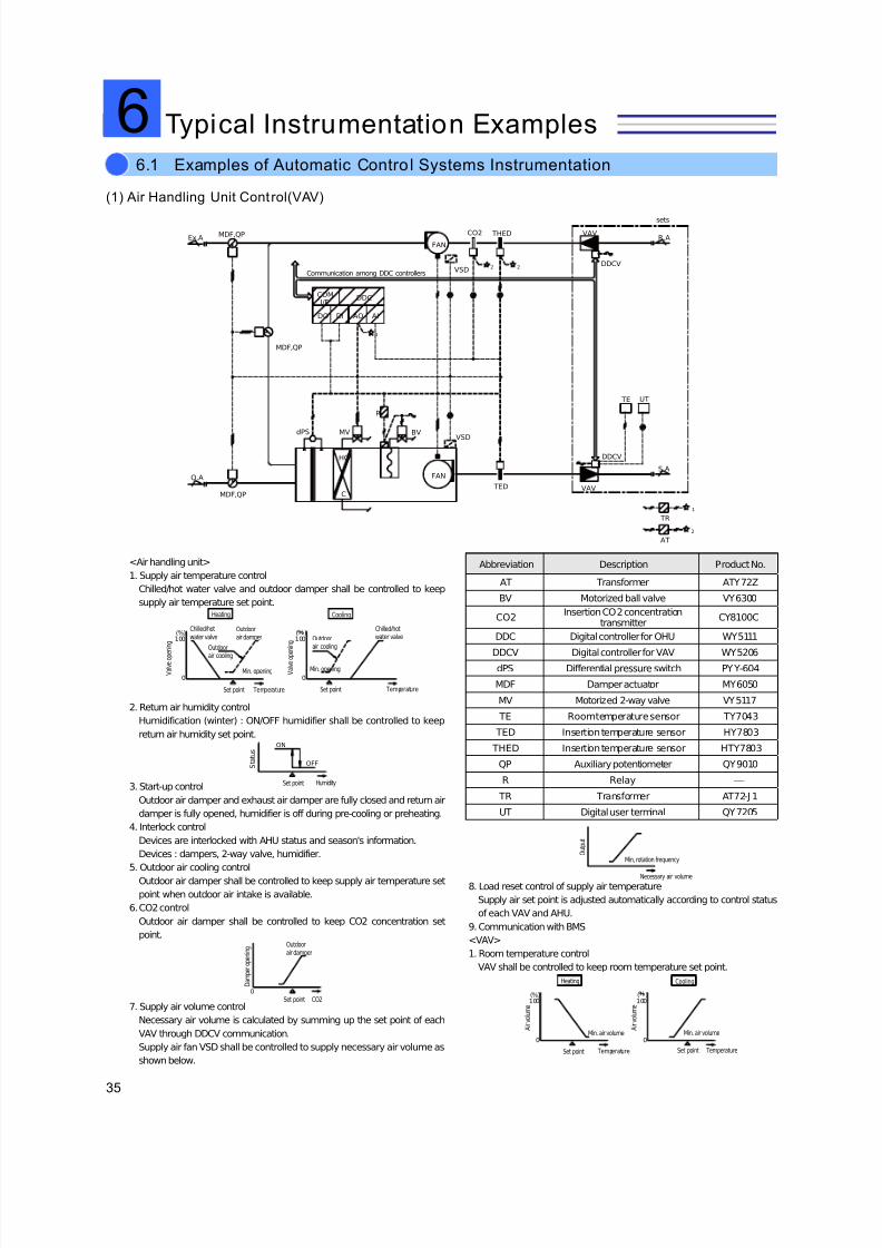
7/23/2019 BMS Design Guide
http://slidepdf.com/reader/full/bms-design-guide 37/90
35
6. Typical Instrumentation Examples
(1) Air Handling Unit Control(VAV)
DDCV
UT
VSD
sets
TE
DDCV
1
O.A
Ex.A
2 2
FAN
MV
C
HC
R
THED
TED
BV
CO2
dPS
VAV
VAV
R.A
S.A
VSD
MDF,QP
MDF,QP
FAN
TR
1
AT
2
MDF,QP
DDCCOMI/F
AIAODIDO
<Air handling unit>
1. Supply air temperature control
Chilled/hot water valve and outdoor damper shall be controlled to keep
supply air temperature set point.
0
100
0
100(%) ( )
2. Return air humidity control
Humidification (winter) : ON/OFF humidifier shall be controlled to keep
return air humidity set point.ON
OFF
3. Start-up control
Outdoor air damper and exhaust air damper are fully closed and return air
damper is fully opened, humidifier is off during pre-cooling or preheating.
4. Interlock control
Devices are interlocked with AHU status and season's information.
Devices : dampers, 2-way valve, humidifier.
5. Outdoor air cooling control
Outdoor air damper shall be controlled to keep supply air temperature set
point when outdoor air intake is available.
6. CO2 control
Outdoor air damper shall be controlled to keep CO2 concentration set
point.
0
7. Supply air volume control
Necessary air volume is calculated by summing up the set point of each
VAV through DDCV communication.
Supply air fan VSD shall be controlled to supply necessary air volume as
shown below.
Abbreviation Description Product No.
AT Transformer ATY72Z
BV Motorized ball valve VY6300
CO2Insertion CO2 concentration
transmitterCY8100C
DDC Digital controller for OHU WY5111
DDCV Digital controller for VAV WY5206dPS Differential pressure switch PYY-604
MDF Damper actuator MY6050
MV Motorized 2-way valve VY5117
TE Room temperature sensor TY7043
TED Insertion temperature sensor HY7803
THED Insertion temperature sensor HTY7803
QP Auxiliary potentiometer QY9010
R Relay ⎯
TR Transformer AT72-J 1
UT Digital user terminal QY7205
8. Load reset control of supply air temperature
Supply air set point is adjusted automatically according to control status
of each VAV and AHU.
9. Communication with BMS
<VAV>
1. Room temperature control
VAV shall be controlled to keep room temperature set point.
0
100
0
100(%) ( )
Communication among DDC controllers
Heating Cooling
Chilled/hotwater valve
V a l v e o p
e n i n g
Outdoorair damper
Outdoor
air cooling
Min. opening
Set point Temperature
Chilled/hotwater valveOutdoor
air cooling
Min. opening V a l v e o p
e n i n g
Set point Temperature
Set point
S t a t u s
Humidity
Set point CO2
Outdoorair damper
D a m p e r o p e n i n g
Min, rotation frequency O u t p u t
Necessary air volume
Set point Temperature
Min. air volume A i r v o l u m e
Heating Cooling
Set point Temperature
Min. air volume A i r v o l u m e
Typical Instrumentation Examples66.1 Examples of Automatic Contro l Systems Instrumentation
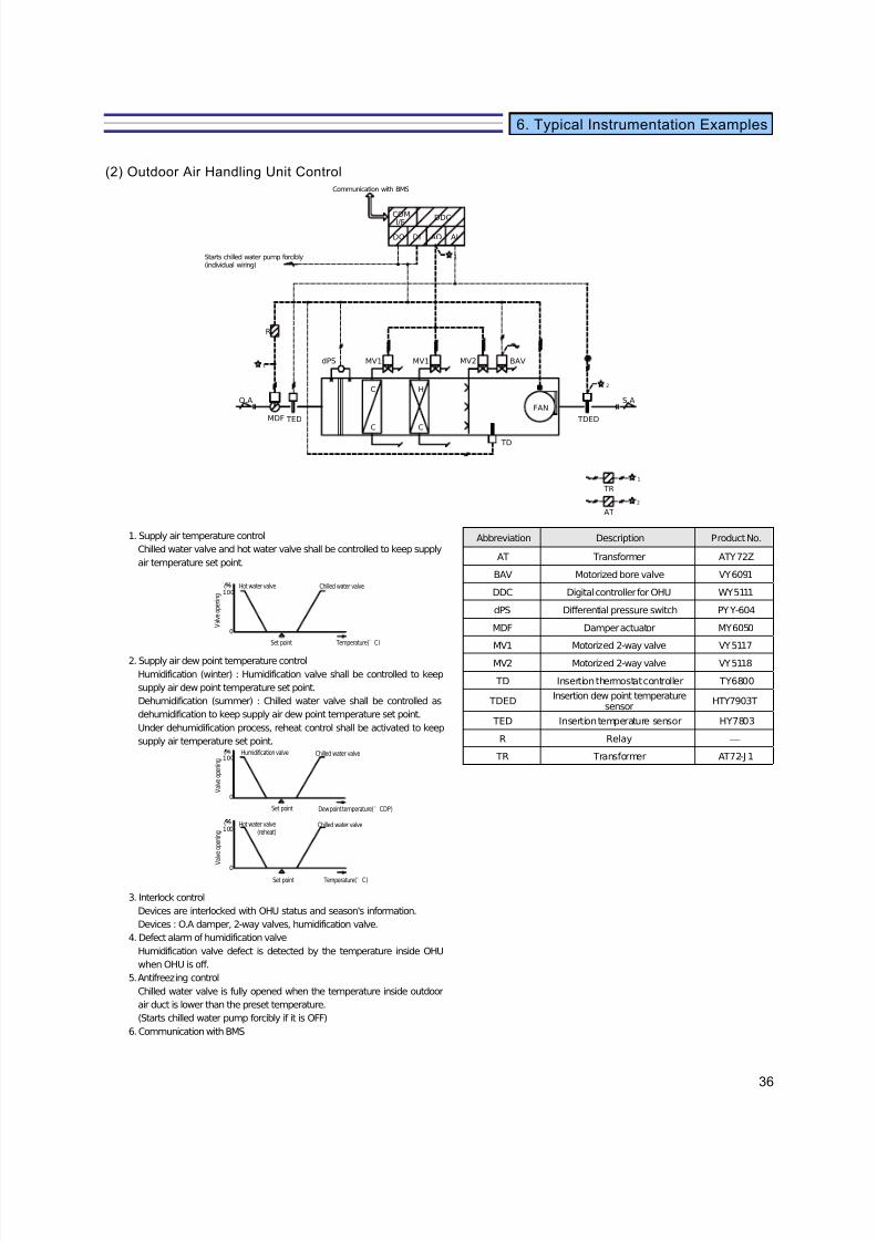
7/23/2019 BMS Design Guide
http://slidepdf.com/reader/full/bms-design-guide 38/90
36
6. Typical Instrumentation Examples
(2) Outdoor Air Handling Unit Control
MV1
C
C
C
H
TED TDED
BAVMV2MV1
TD
FAN
1
2
O.A
1
R
S.A
dPS
MDF
DDCCOMI/F
AIAODIDO
TR
1
AT
2
1. Supply air temperature control
Chilled water valve and hot water valve shall be controlled to keep supply
air temperature set point.
100
0
( )
2. Supply air dew point temperature control
Humidification (winter) : Humidification valve shall be controlled to keep
supply air dew point temperature set point.
Dehumidification (summer) : Chilled water valve shall be controlled as
dehumidification to keep supply air dew point temperature set point.
Under dehumidification process, reheat control shall be activated to keep
supply air temperature set point.
100
0
( )
100
0
( )
3. Interlock control
Devices are interlocked with OHU status and season's information.
Devices : O.A damper, 2-way valves, humidification valve.
4. Defect alarm of humidification valve
Humidification valve defect is detected by the temperature inside OHU
when OHU is off.
5. Antifreezing control
Chilled water valve is fully opened when the temperature inside outdoor
air duct is lower than the preset temperature.
(Starts chilled water pump forcibly if it is OFF)
6. Communication with BMS
Abbreviation Description Product No.
AT Transformer ATY72Z
BAV Motorized bore valve VY6091
DDC Digital controller for OHU WY5111
dPS Differential pressure switch PYY-604
MDF Damper actuator MY6050
MV1 Motorized 2-way valve VY5117
MV2 Motorized 2-way valve VY5118
TD Insertion thermostat controller TY6800
TDEDInsertion dew point temperature
sensorHTY7903T
TED Insertion temperature sensor HY7803
R Relay ⎯
TR Transformer AT72-J 1
Hot water valve
V a l v e o p e n i n g
Chilled water valve
Set point Temperature(°C)
Humidification valve
V a l v e o p e n i n g
Chilled water valve
Set point Dew point temperature(°CDP)
Hot water valve(reheat)
V a l v e o p e n i n g
Chilled water valve
Set point Temperature(°C)
Starts chilled water pump forcibly(individual wiring)
Communication with BMS
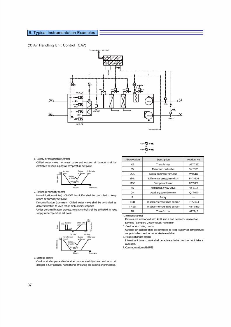
7/23/2019 BMS Design Guide
http://slidepdf.com/reader/full/bms-design-guide 39/90
37
6. Typical Instrumentation Examples
(3) Air Handling Unit Control (CAV)
MDF,QP
MDF
MDF
MDF,QP
MDF,QP
TED
Ex.A
O.A1
1
dPS MV
FAN
H
C
MV
C
C
FAN
RR
BV
R
TR
1
AT
2
1
S.A
2
THED
R.A
DDCCOMI/F
AIAODIDO
1. Supply air temperature control
Chilled water valve, hot water valve and outdoor air damper shall be
controlled to keep supply air temperature set point.
0
(%)100
2. Return air humidity control
Humidification (winter) : ON/OFF humidifier shall be controlled to keep
return air humidity set point.
Dehumidification (summer) : Chilled water valve shall be controlled as
dehumidification to keep return air humidity set point.
Under dehumidification process, reheat control shall be activated to keep
supply air temperature set point.
OFF
ON
0
(%)100
0
(%)100
3. Start-up control
Outdoor air damper and exhaust air damper are fully closed and return air
damper is fully opened, humidifier is off during pre-cooling or preheating.
Abbreviation Description Product No.
AT Transformer ATY72Z
BV Motorized ball valve VY6300
DDC Digital controller for OHU WY5111
dPS Differential pressure switch PYY-604
MDF Damper actuator MY6050
MV Motorized 2-way valve VY5117
QP Auxiliary potentiometer QY9010
R Relay ⎯
TED Insertion temperature sensor HY7803
THED Insertion temperature sensor HTY7803
TR Transformer AT72-J 1
4. Interlock control
Devices are interlocked with AHU status and season's information.
Devices : dampers, 2-way valves, humidifier.
5. Outdoor air cooling control
Outdoor air damper shall be controlled to keep supply air temperature
set point when outdoor air intake is available.
6. Heat exchanger control
Intermittent timer control shall be activated when outdoor air intake is
available.
7. Communication with BMS
Hot watervalve
V a l v e o p e n i n g
Outdoorair damper
Outdoorair cooling
Min. opening
Set point Temperature
Chiller watervalve
Humidifier Chilled watervalve
Set point Humidity
S t a t u s
V a l v
e o p e n i n g
Communication with BMS
Hot water valve(reheat)
V a l v e o p e n i n g
Outdoorair damper
Outdoorair cooling
Min. opening
Set point Temperature
Chiller watervalve

7/23/2019 BMS Design Guide
http://slidepdf.com/reader/full/bms-design-guide 40/90
38
6. Typical Instrumentation Examples
(4) Fan Coil Unit Control (zone contro l)
CHS
CHR
UT
(x3)
TE
R
TR
MV
C
HC
C
HC
FAN
C
HC
C
HC
FAN
C
HC
C
HC
FAN
DDCF
Abbreviation Description Product No.
DDCF Temperature controller WY5205MV Motorized 2-way valve VY5120
R Relay ⎯
TE Room temperature sensor TY7043
TR Transformer AT72-J 1
UT Digital user terminal QY7205
1. Room temperature control
2-way valve shall be controlled to keep room
temperature set point.
2. Fan ON/OFF operation
ON/OFF operation of fan coil unit is done by user
terminal (UT).
3. Interlock control
Devices are interlocked with FCU status.
Devices : 2-way valve.4. Heating/cooling changeover
Heating/cooling changeover command comes from
BMS.
5. Communication with BMS
(5) Fan Coil Unit Control (DDC)
CR
CS
HS
HR
UT TE
FAN FAN
C
C
C
H
C
C
C
H
DDCFDDCF
MVV
MVV
MVV
MVV
Abbreviation Description Product No.
DDCF Temperature controller WY5205
MVV Motorized 2-way valveVY5502
+MY5560C
TE Room temperature sensor TY7043
UT Digital user terminal QY7205
1. Room temperature control
2-way valve shall be controlled to keep room
temperature set point.
2. Fan ON/OFF operation
ON/OFF operation of fan coil unit is done by user
terminal (UT).
3. Interlock control
Devices are interlocked with FCU status.
Devices : 2-way valves.
4. Fan coil unit interlock by network communication
Group operations of fan ON/OFF, valve control and air
volume changeover are done by network
communication.5. Communication with BMS
・Display・Setting・ON/OFF
・Air volumechangeover
Communication with BMS
LAN cable
・Display・Setting・ON/OFF・Air volume
changeover
Communication with BMS
LAN cable
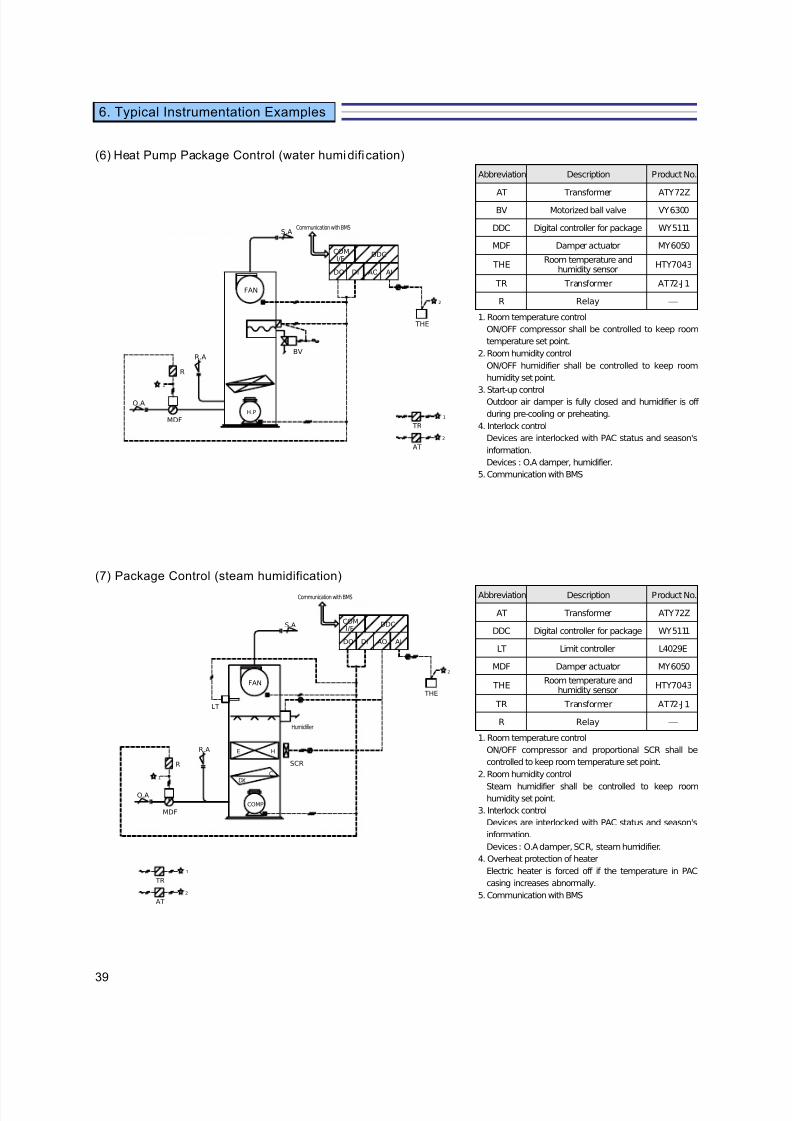
7/23/2019 BMS Design Guide
http://slidepdf.com/reader/full/bms-design-guide 41/90
39
6. Typical Instrumentation Examples
(6) Heat Pump Package Control (water humidifi cation)
MDF
FAN
H.P
BV
R
S.A
R.A
O.A
1
THE
2
TR
1
AT
2
DDCCOMI/F
AIAODIDO
Abbreviation Description Product No.
AT Transformer ATY72ZBV Motorized ball valve VY6300
DDC Digital controller for package WY5111
MDF Damper actuator MY6050
THERoom temperature and
humidity sensorHTY7043
TR Transformer AT72-J 1
R Relay ⎯
1. Room temperature control
ON/OFF compressor shall be controlled to keep room
temperature set point.
2. Room humidity control
ON/OFF humidifier shall be controlled to keep room
humidity set point.
3. Start-up controlOutdoor air damper is fully closed and humidifier is off
during pre-cooling or preheating.
4. Interlock control
Devices are interlocked with PAC status and season's
information.
Devices : O.A damper, humidifier.
5. Communication with BMS
(7) Package Control (steam humidification)
MDF
LT
SCR
S.A
O.A
R.A HE
COMP
C
DX
FAN
R
1
THE
2
TR
1
AT
2
DDCCOMI/F
AIAODIDO
Abbreviation Description Product No.
AT Transformer ATY72Z
DDC Digital controller for package WY5111
LT Limit controller L4029E
MDF Damper actuator MY6050
THERoom temperature and
humidity sensorHTY7043
TR Transformer AT72-J 1
R Relay ⎯
1. Room temperature control
ON/OFF compressor and proportional SCR shall be
controlled to keep room temperature set point.
2. Room humidity control
Steam humidifier shall be controlled to keep roomhumidity set point.
3. Interlock control
Devices are interlocked with PAC status and season's
information.
Devices : O.A damper, SCR, steam humidifier.
4. Overheat protection of heater
Electric heater is forced off if the temperature in PAC
casing increases abnormally.
5. Communication with BMS
Communication with BMS
Communication with BMS
Humidifier

7/23/2019 BMS Design Guide
http://slidepdf.com/reader/full/bms-design-guide 42/90
40
6. Typical Instrumentation Examples
(8) Chiller Plant System Control (1-pump system)
TEW
dPEW
TEW
FM
TEW TEW
TEW
TEW TEW
TEW TEW
TEW TEW
HC C
MV
Temperature
Temperature
Temperature
Temperature
Chiller
Chiller
Chiller
Chiller
TR
PMX
COM
I/F
AIAODIDO
1. Sequence control of chiller
(1)Chiller number control
Number of chiller is calculated according to load flow rate and sequence
control is done followed with setting table as shown below diagram.
NO.1,2,3,4
NO.1,2
NO.1,2,3
NO.1
(2)Rotation control
Rotation function shall be incorporated in this sequence control to
equalize running time of chiller.
(3)Skip control
Defected chiller shall be excluded from sequence control by
automatically.
(4)Number calculation compensation
Running number of chillers shall be adjusted by supply temperature
(above set point) and return header temperature (below set point).
Abbreviation Description Product No.
DC DC 24V power supply RYY792D
dPEW Differential pressure transmitter J TD
FM Electromagnetic flow meterMGG10C/MGG11
MV Motorized 2-way valve VY5113J
PMXDigital controller for chiller plant
systemWY2001Q
TEW Pipe insertion temperature sensor TY7830B
TR Transformer AT72-J 1
2. Header bypass valve control
Proportional header bypass valve shall be controlled as shown below,
to keep constant the differential pressure between headers.
(However, bypass valve is fully opened when the pumps are all off.)
To avoid sudden increase in pressure, bypass valve is forced open
before the batch ON command or the increase in number of operating
equipment.
SP0
3. Communication with BMS
NO.1 rated capacity
N o . o f c h i l l e r o p e r a t e d
NO.1,2,3 rated capacity
NO.1,2 rated capacity
Flow rate
Bypass valve opening
V a l v e o p e n i n g
Differential pressure
Communication with BMS
:Monitored by BMS
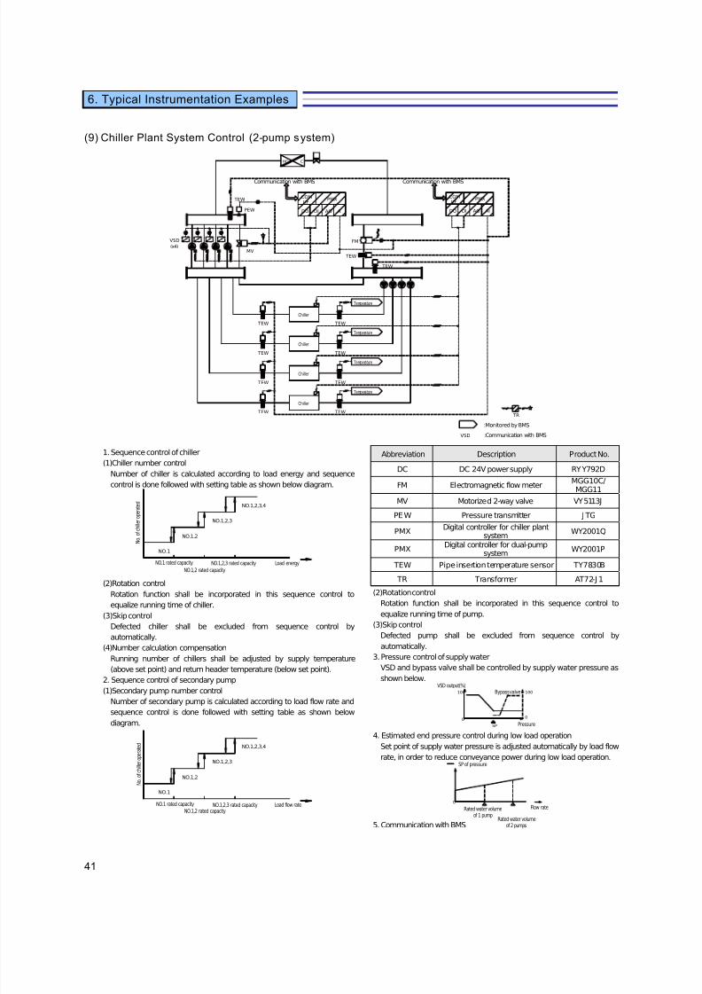
7/23/2019 BMS Design Guide
http://slidepdf.com/reader/full/bms-design-guide 43/90
41
6. Typical Instrumentation Examples
(9) Chiller Plant System Control (2-pump system)
HC C
(x4)
VSD
MV
TEW
PEW
TEW
TEW
FM
TEW
TEW
TEW
TEW TEW
TEW
TEW
TEW
Temperature
Temperature
Temperature
Temperature
PMXCOMI/F
AIAODIDO
Chiller
Chiller
Chiller
Chiller
TR
VSD
PMXCOMI/F
AIAODIDO
1. Sequence control of chiller
(1)Chiller number control
Number of chiller is calculated according to load energy and sequence
control is done followed with setting table as shown below diagram.
NO.1,2,3,4
NO.1,2,3
NO.1
NO.1,2
(2)Rotation control
Rotation function shall be incorporated in this sequence control to
equalize running time of chiller.
(3)Skip control
Defected chiller shall be excluded from sequence control by
automatically.
(4)Number calculation compensation
Running number of chillers shall be adjusted by supply temperature
(above set point) and return header temperature (below set point).
2. Sequence control of secondary pump
(1)Secondary pump number control
Number of secondary pump is calculated according to load flow rate and
sequence control is done followed with setting table as shown below
diagram.
NO.1,2,3,4
NO.1,2,3
NO.1
NO.1,2
Abbreviation Description Product No.
DC DC 24V power supply RYY792D
FM Electromagnetic flow meterMGG10C/MGG11
MV Motorized 2-way valve VY5113J
PEW Pressure transmitter J TG
PMXDigital controller for chiller plant
systemWY2001Q
PMXDigital controller for dual-pump
systemWY2001P
TEW Pipe insertion temperature sensor TY7830B
TR Transformer AT72-J 1
(2)Rotation control
Rotation function shall be incorporated in this sequence control to
equalize running time of pump.
(3)Skip control
Defected pump shall be excluded from sequence control by
automatically.
3. Pressure control of supply water
VSD and bypass valve shall be controlled by supply water pressure as
shown below.
0
100
SP
0
100
4. Estimated end pressure control during low load operation
Set point of supply water pressure is adjusted automatically by load flow
rate, in order to reduce conveyance power during low load operation.
0
5. Communication with BMS
NO.1 rated capacity
N o . o f c h i l l e
r o p e r a t e d
NO.1,2,3 rated capacity
NO.1,2 rated capacity
Load energy
NO.1 rated capacity
N o . o f c h i l l e r o p e r a t e d
NO.1,2,3 rated capacityNO.1,2 rated capacity
Load flow rate
VSD output(%)Bypass valve
Pressure
SP of pressure
Rated water volumeof 1 pump
Rated water volumeof 2 pumps
Flow rate
Communication with BMS
:Monitored by BMS
:Communication with BMS
Communication with BMS

7/23/2019 BMS Design Guide
http://slidepdf.com/reader/full/bms-design-guide 44/90
42
6. Typical Instrumentation Examples
(10) System Configuration Diagram
MS
PC
KB
LCD
<Client PC >
CLP
P
SCS
RS
RS
RS
SMSDSS
User PC
RS
SCS
PMX
DDC
ZM
UT
UT
DDCV
DDCF
BMIF
To SCS
RS
kVA
UPS
P
Referential Outlook and Dimension
MSKB
PC
CLP
1400
8 0 0
7 0 0
LCD
SP SP
700
5 0
1 9 5 0
400
220 530
5 0 0
AC/GC V A
Individual grounding(class D)
Primary power failure alarmBattery low alarmFailure
Fire AlarmPanel Fire Signal
Substation,generator
Power supply statusSwitching breaker of generator-commercial power
Electric work
DistributionCircuit
Relay timercircuitfor power failure/
restoration judgment
SystemControl Panel
Relay Circuit
Power supply to ※ mark
Power supply to ※ mark
To SCS(Power supply statusof AC/GC and generator)
<Building Management System> <System Control Panel> <UPS>
3kVABackup 10 minutes
Building Management System
IPv4/v6 Network(BACnet)
NC-bus/LC-bus
Individual Wiring
RS-232C
Substation
Power
Panel
DistributionPanel
AuxiliaryPanel
Lighting SystemInterface
Sensor
Flow meter
Sensor・Setter
AHU C ontrol
Valve
Valve
Chiller Plant Control
Sensor・Setter
ValveFCU Control
SC-bus
Sensor・Setter
VAV
VAV C ontrol
Building Multi SystemInterface
Converter(Ethernet/RS-485 conversion)
RS-485
Controller, Power Meter
OtherManufacturer's
BACnet Devices
HVAC・Plumbing・Electricity
NC-bus/LC-bus
Individual Wiring
Individual Wiring
RS-232C
Individual Wiring

7/23/2019 BMS Design Guide
http://slidepdf.com/reader/full/bms-design-guide 45/90
43
6. Typical Instrumentation Examples
Building Management System Hardware Specifications (1/2)
Symbol Name Description Specifications
PC Client PC Display and operation of system managementinformation, setting and changing of variousprograms are done through Web browser.A mouse is used for screen selection and operation.
CPUMain storage capacityHDDCD-ROM drivePowerOSWeb browser
J AVAvm1.4 embeddedSVG Viewer3.0 and aboveembedded・XGA supportAdobe Reader 6.0 andabove embedded
Mouse(MS)
: Pentium4 3.0GHz and above: 512MB and above: 40GB and above: 24-speed and above: AC100/200V +/-10%, 50/60Hz: WindowsXP: IE6.0
: optical
LCD(PC)
Color GraphicDisplay
As the main display unit, LCD displays various listsand graphics.It can display graphics, data simultaneously withmulti windows.
SizeDisplay colorsDisplay characters
Resolution
: 17 / 19 inch type: 16190000 colors and above: Alphanumeric, Kana,Hiragana, Kanji (J IS level 1st&2nd), symbols and drawings
: 1024x768 / 1280x1024 pixels
DSS Data StorageServer
Performs the overall system management, periodicaldata collection, data storage, data processing, etc.It also controls input/output of peripheral devices.
CPUMain storage capacityOSHDDMax. data points
Power
: 32-bit: SDRAM 256MB: Linux: 40GB (24-hour run): 2000/5000/10000/20000/30000 objects
: AC100/200V +/-10%, 50/60Hz,50VA
SMS SystemManagementServer
Performs display, setting and operation of the overallsystem management information (graphics, points,programs, etc.) through web browser software of theclient PC.
CPUMain storage capacityOSHDDMax. data points
Power
Number of graphics
: 32-bit: SDRAM 256MB: Linux: 40GB(24-hour run): 2000/5000/10000/20000/30000 objects
: AC100/200V +/-10%, 50/60Hz,50VA
: graphics
SCS System CoreServer
Performs data transmission with RS and DDC, manages point data and schedule control.It also stores trend data.
CPUMain storage capacityOSMax. data pointsCommunication linePower
: 32-bit: SDRAM 128MB: Linux: Max. 1000 objects/unit: 4 lines/unit: AC100/200V +/-10%, 50/60Hz,70VA
CLP Color Printer Prints various data as follows.1. daily, monthly and yearly reports2. trend data3. various lists (alarm dashboard)4. maintenance messages5. screen
Printing methodPrinting colorPaper sizePower
Temperature conditionConnection
: Semiconductor laser: Full color: A4: AC100/200V +/-10%, 50/60Hz: 10-35℃ : IPv4/v6 network
IPv4/v6Network
Backbone network of BMS for data transmission.It has transmission protocols such as IEIEj/pBACnet, HTTP, etc.
Communication method
Communication speedWiring
: Ethernet, TCP/IP protocols, IPv4 or IPv6
: 10Mbps, 100Mbps: 100BASE-TX, 100BASE-FX
UPS UninterruptiblePower System
Provides uninterruptible power to client PC, serversand other necessary terminal transmitters.
InputOutput
Time backupBattery typeBackup method
: AC/GC V A: AC V A: minutes: Compact size sealed lead-acid: Online power system
NC-bus New ControllerBus
Transmits data between BMS and terminaltransmitters.
Communication methodCommunication speedWiring
: Private communication: 4800bps: IPEV-S 0.9-1P (twisted paircable)
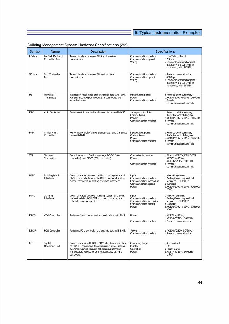
7/23/2019 BMS Design Guide
http://slidepdf.com/reader/full/bms-design-guide 46/90
44
6. Typical Instrumentation Examples
Building Management System Hardware Specifications (2/2)
Symbol Name Description Specifications
LC-bus LonTalk ProtocolController Bus
Transmits data between BMS and terminal transmitters.
Communication methodCommunication speedWiring
: Lon-Talk protocol: 78kbps: Lan cable, connector joint (category 3-5 0.5φ*4P in conformity with EIA568)
SC-bus Sub ControllerBus
Transmits data between ZM and terminal transmitters.
Communication methodCommunication speedWiring
: Private communication: 4800bps: Lan cable, connector joint (category 3-5 0.5φ*4P in conformity with EIA568)
RS Terminal Transmitter
Installed in local place and transmits data with BMS.RS and input/output devices are connected withindividual wires.
Input/output pointsPowerCommunication method
: Refer to point summary: AC100/200V +/-10%, 50/60Hz: Privatecommunication/Lon-Talk
DDC AHU Controller Performs AHU control and transmits data with BMS. Input/output pointsControl itemsPowerCommunication method
: Refer to point summary: Refer to control diagram: AC100/200V +/-10%, 50/60Hz: Privatecommunication/Lon-Talk
PMX Chiller PlantController
Performs control of chiller plant system and transmitsdata with BMS.
Input/output pointsControl itemsPowerCommunication method
: Refer to point summary: Refer to control diagram: AC100/200V +/-10%, 50/60Hz: Privatecommunication/Lon-Talk
ZM Terminal Transmitter
Coordinates with BMS to manage DDCV (VAV controller) and DDCF (FCU controller).
Connectable numberPower
Communication method
: 50 units(DDCV, DDCF)/ZM: AC24V +/-15% /AC100V-200V, 50/60Hz
: Privatecommunication/Lon-Talk
BMIF Building MultiInterface
Communicates between building multi system andBMS, transmits data of ON/OFF command, status,alarm, temperature setting and measurement.
InputCommunication methodCommunication procedureCommunication speedPower
: Max. 64 systems: Polling/Selecting method (equal to J ISIIX5002)
: 4800bps: AC100/200V +/-10%, 50/60Hz,20VA
RU-L LightingInterface
Communicates between lighting system and BMS, transmits data of ON/OFF command, status, andschedule management.
InputCommunication methodCommunication procedureCommunication speedPower
: Max. 64 systems: Polling/Selecting method (equal to J ISIIX5002)
: 1200bps: AC100/200V +/-10%, 50/60Hz,20VA
DDCV VAV Controller Performs VAV control and transmits data with BMS. Power
Communication method
: AC24V +/-15% /AC100V-240V, 50/60Hz
: Private communication
DDCF FCU Controller Performs FCU control and transmits data with BMS. PowerCommunication method
: AC100V-240V, 50/60Hz: Private communication
UT DigitalOperating Unit
Communicates with BMS, DDC, etc., transmits data of ON/OFF command, temperature display, setting, overtime running request schedule adjustment.It is possible to restrict on the access by using apassword.
Operating targetDisplayOperationPower
: 4 zones/unit: LCD: Touch panel: AC24V +/-15%, 50/60Hz,1.5VA
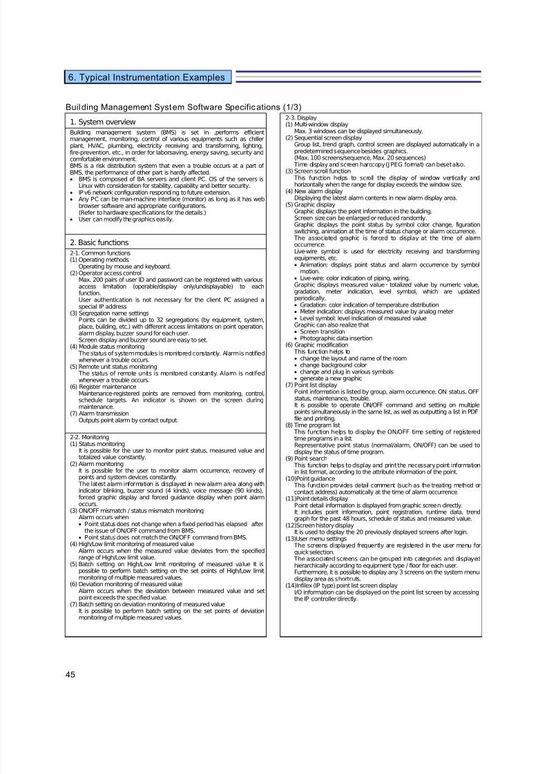
7/23/2019 BMS Design Guide
http://slidepdf.com/reader/full/bms-design-guide 47/90
45
6. Typical Instrumentation Examples
Building Management System Software Specifications (1/3)
1. System overview2-3. Display(1) Multi-window display
Max. 3 windows can be displayed simultaneously.(2) Sequential screen display
Group list, trend graph, control screen are displayed automatically in apredetermined sequence besides graphics.(Max. 100 screens/sequence, Max. 20 sequences)
Time display and screen hardcopy (J PEG format) can beset also.(3) Screen scroll function
This function helps to scroll the display of window vertically andhorizontally when the range for display exceeds the window size.
(4) New alarm displayDisplaying the latest alarm contents in new alarm display area.
(5) Graphic displayGraphic displays the point information in the building.Screen size can be enlarged or reduced randomly.Graphic displays the point status by symbol color change, figurationswitching, animation at the time of status change or alarm occurrence.
The associated graphic is forced to display at the time of alarmoccurrence.Live-wire symbol is used for electricity receiving and transformingequipments, etc.• Animation: displays point status and alarm occurrence by symbol
motion.• Live-wire: color indication of piping, wiring.Graphic displays measured value・totalized value by numeric value,gradation, meter indication, level symbol, which are updatedperiodically.• Gradation: color indication of temperature distribution• Meter indication: displays measured value by analog meter• Level symbol: level indication of measured valueGraphic can also realize that• Screen transition• Photographic data insertion
(6) Graphic modification This function helps to• change the layout and name of the room• change background color• change and plug in various symbols• generate a new graphic
(7) Point list displayPoint information is listed by group, alarm occurrence, ON status, OFFstatus, maintenance, trouble.
It is possible to operate ON/OFF command and setting on multiplepoints simultaneously in the same list, as well as outputting a list in PDFfile and printing.
(8) Time program list This function helps to display the ON/OFF time setting of registeredtime programs in a list.Representative point status (normal/alarm, ON/OFF) can be used todisplay the status of time program.
(9) Point search This function helps to display and print the necessary point informationin list format, according to the attribute information of the point.
(10)Point guidance This function provides detail comment (such as the treating method orcontact address) automatically at the time of alarm occurrence.
(11)Point details displayPoint detail information is displayed from graphic screen directly.It includes point information, point registration, runtime data, trendgraph for the past 48 hours, schedule of status and measured value.
(12)Screen history displayIt is used to display the 20 previously displayed screens after login.
(13)User menu settings The screens displayed frequently are registered in the user menu forquick selection.
The associated screens can be grouped into categories and displayedhierarchically according to equipment type / floor for each user.Furthermore, it is possible to display any 3 screens on the system menudisplay area as shortcuts.
(14)Infilex (IP type) point list screen displayI/O information can be displayed on the point list screen by accessingthe IP controller directly.
Building management system (BMS) is set in ,performs efficient
management, monitoring, control of various equipments such as chiller plant, HVAC, plumbing, electricity receiving and transforming, lighting,fire-prevention, etc., in order for laborsaving, energy saving, security andcomfortable environment.BMS is a risk distribution system that even a trouble occurs at a part of BMS, the performance of other part is hardly affected.• BMS is composed of BA servers and client PC. OS of the servers is
Linux with consideration for stability, capability and better security.• IPv6 network configuration responding to future extension.• Any PC can be man-machine interface (monitor) as long as it has web
browser software and appropriate configurations.(Refer to hardware specifications for the details.)
• User can modify the graphics easily.
2. Basic functions
2-1. Common functions(1) Operating methods
Operating by mouse and keyboard.
(2) Operator access controlMax. 200 pairs of user ID and password can be registered with variousaccess limitation (operable/display only/undisplayable) to eachfunction.User authentication is not necessary for the client PC assigned aspecial IP address
(3) Segregation name settingsPoints can be divided up to 32 segregations (by equipment, system,place, building, etc.) with different access limitations on point operation,alarm display, buzzer sound for each user.Screen display and buzzer sound are easy to set.
(4) Module status monitoring The status of system modules is monitored constantly. Alarm is notifiedwhenever a trouble occurs.
(5) Remote unit status monitoring The status of remote units is monitored constantly. Alarm is notifiedwhenever a trouble occurs.
(6) Register maintenanceMaintenance-registered points are removed from monitoring, control,schedule targets. An indicator is shown on the screen during
maintenance.(7) Alarm transmission
Outputs point alarm by contact output.
2-2. Monitoring(1) Status monitoring
It is possible for the user to monitor point status, measured value andtotalized value constantly.
(2) Alarm monitoringIt is possible for the user to monitor alarm occurrence, recovery of points and system devices constantly.
The latest alarm information is displayed in new alarm area along withindicator blinking, buzzer sound (4 kinds), voice message (90 kinds),forced graphic display and forced guidance display when point alarmoccurs.
(3) ON/OFF mismatch / status mismatch monitoringAlarm occurs when• Point status does not change when a fixed period has elapsed after
the issue of ON/OFF command from BMS.• Point status does not match the ON/OFF command from BMS.
(4) High/Low limit monitoring of measured valueAlarm occurs when the measured value deviates from the specifiedrange of High/Low limit value.
(5) Batch setting on High/Low limit monitoring of measured value It ispossible to perform batch setting on the set points of High/Low limitmonitoring of multiple measured values.
(6) Deviation monitoring of measured valueAlarm occurs when the deviation between measured value and setpoint exceeds the specified value.
(7) Batch setting on deviation monitoring of measured valueIt is possible to perform batch setting on the set points of deviationmonitoring of multiple measured values.
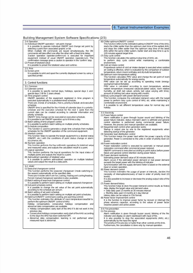
7/23/2019 BMS Design Guide
http://slidepdf.com/reader/full/bms-design-guide 48/90
46
6. Typical Instrumentation Examples
Building Management System Software Specifications (2/3)2-4. Operation(1) Individual ON/OFF operation・set point change
It is possible to operate individual ON/OFF and change set point byselecting a point from associated graphic or list.When multiple ON commands are issued simultaneously, the ONcommands will take effect one after the other with a fixed time delay.3-action operation (operate-confirm-run) is executed for importantequipment instead of usual ON/OFF operation (operate-run). Theconfirmation message gives a caution to operator in the 'confirm' step.
(2) Preset of totalized valueIt is possible to preset the totalized value and runtime.
(6) Chiller optimum ON/OFF control This function refers to the estimated optimum ON/OFF time of the AHU,starts the chiller earlier than the optimum start time of the earliest AHU,and stops the chiller earlier than the optimum stop time of the latestAHU within the same chiller system. Earlier start and stop time is up to120 minutes against target time.
(7) Duty cycle control This function calculates the optimum stop time of AHU, etc.to perform duty cycle control while maintaining a comfortableenvironment.
(8) Cold air intake controlProportional control of cold air intake damper is executed when outdoorair cooling is effective, which is evaluated by the comparison of outdoortemperature, return (room) enthalpy and dry-bulb temperature
(9) Optimum room temperature setting This function calculates PMV value and change the set point of roomtemperature automatically for energy-saving.PMV value can be set up according to operating mode (energy-saving/normal/comfortable).PMV value is calculated according to room temperature, windowradiant temperature (measured value/calculated value), room relativehumidity, air draft (set value), activity (set value varying with time),amount of clothing (set value varying with month).
(10)Duty cycle program with power demand function This function compares the estimated demand value with the targetpower to perform duty cycle control of AHU, etc. while maintaining acomfortable environment.It is possible to set different temperature value for normal day andholiday.
2-5. Print(1) Screen print
It is possible to print and spool the currently displayed screen by using aspecified printer.
3. Control functions
3-1. Common(1) Calendar control
It is possible to specify normal days, holidays, special days 1 andspecial days 2 till for 2 years ahead.
(2) Time program controlON/OFF operation of the equipment registered in time program isexecuted automatically in a predetermined schedule.
There are 2 kinds of schedules, that is, priority schedule and executionschedule.ON/OFF time is specified for the 4 kinds of calendar days in a priorityschedule and the execution schedule for the next 1 week from thecurrent date can be created according to calendar information andpriority schedule.ON/OFF time change can be executed on execution schedule.It is possible to set ON/OFF operation up to 8 times a day.
(3) Batch setting of time program controlIt is possible to perform batch setting on multiple priority schedules.
(4) Schedule composition This function is used to generate a single time schedule from multipleschedules for the ON/OFF operation of the communal equipment.
(5) Interlock control This function helps to operate the target equipment to a desired status(ON/OFF, etc.) with the conditions of point status change or alarmoccurrence, etc.
(6) Numeric operation This function performs the four arithmetic operations for totalized valueand measured value, and outputs the calculation result to a point.
(7) Logical operation This function performs the logical operations for the input status of multiple points and outputs the result to a point.
(8) Add-subtract operation of totalized valueIt is possible to perform add-subtract operation on multiple totalizedvalues and output the result to a data point.
3-3. Electricity(1) Power failure control
Alarm notification is given through buzzer sound and blinking of thepower failure indicator, status mismatch alarm is withheld and generalcontrol retention is performed during commercial power failure.However, fire process and manual operation are available.
(2) Sequential start control when generator worksStartup is output one by one to the registered equipments whendetecting startup of the generator.
(3) Generator load distribution control This function keeps the power load within the power capacity of thegenerator. Power is connected to the units in order of priority level (15levels).
(4) Power restoration controlPower restoration control is executed by automatic or manual powerrestoration command after commercial power restored.ON/OFF command is executed according to point status before powerfailure and general control retention during power failure.
(5) Power demand monitoringEstimating power demand value of 30 minutes interval.Alarm occurs if the estimated power demand or real power demandexceeds the target power with the blinking of indicator.Synchronization with the supply demand meter is based on the externalinput or screen operation.
(6) Power demand control This function estimates the usage of power at intervals, decides thenecessity of interruption/recovery of load in order of priority level (15levels).It is also possible to increase or decrease the analog output ratio of theinverter.
(7) Power demand history This function helps to store the power demand control results as historydata, display the target value and demand value.
• Daily data: past 13 months at 30 minutes interval• Monthly data: past 13 months at 1 day intervalHistory data can be output in CSV format.
(8) Power factor improvement controlIt is the function to improve power factor by recover or interrupt thephase advance capacitor, according to the values of power factor(reactive power) and active power.
3-2. HVAC(1) Seasonal changeover control
This function performs the seasonal changeover (mode switching onthe season) automatically at the specified date.
There are 4 modes which are fan, cooling, heating and cooling/ heating.Forced manual changeover operation is also available.
(2) Batch setting of seasonal changeover controlIt is possible to perform batch setting on multiple seasonal changeover.
(3) Set point schedule controlIt is possible to change the set value of the set point automaticallyaccording to the schedule per annum.
(4) Batch setting of set point scheduleIt is possible to perform batch setting on multiple set point schedules.
(5) Optimum ON/OFF control (pre-cooling, pre-warming control) This function estimates the attribute of room temperature raise/fall toperform the optimum ON/OFF control of AHU.Holiday compensation, consecutive holidays compensation and abnormal data compensation are available.• Holiday compensation: early start of the AHU if it did not work in the
previous day.• Consecutive holidays compensation: early start of the AHU according
to the days the AHU has been switched OFF.• Abnormal data compensation: learning is not performed when
measured input is abnormal.
3-4. Fire-prevention(1) Fire process
Alarm notification is given through buzzer sound, blinking of the fireindicator and display on alarm dashboard with input of fire.It is also possible to stop the associated equipments (AHU, etc.)automatically by the input fire signal.
The priority of fire process is higher than other controls at this time.Furthermore, fire cancellation is done only by manual operation.
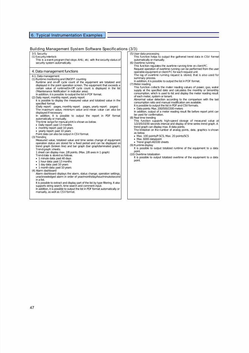
7/23/2019 BMS Design Guide
http://slidepdf.com/reader/full/bms-design-guide 49/90
47
6. Typical Instrumentation Examples
Building Management System Software Specifications (3/3)3-5. Security(1) Security interlock
This is a event program that stops AHU, etc. with the security status of security system automatically.
(5) User data processing This function helps to output the gathered trend data in CSV formatautomatically or manually.
(6) Overtime running This function regulates the overtime running time on client PC.Request operation of overtime running can be performed from the useroperable equipment or client PC for each request unit.
The log of overtime running request is stored, that is also used forsummary process.In addition, it is possible to output the list in PDF format.
(7) Meter reading This function collects the meter reading values of power, gas, watersupply at the specified date and calculates the monthly or bimonthlyconsumption, which is used to list and display the meter reading resultof each meter, system or tenant.Abnormal value detection according to the comparison with the lastconsumption ratio and manual modification are available.It is possible to output the list in PDF and CSV formats.• Data points: Max. 200/500/1500 metersIn addition, output of a meter reading result file before report print canbe used for confirmation.
(8) Real time trending This function supports high-speed storage of measured value at
1/2/3/5/10/30 seconds interval and display of time series trend graph. Atrend graph can display max. 8 data points.
The limitation on the number of analog points, data, graphics is shownas below.• Max. 100 points/P-SCS, Max. 20 points/SCS• Max. 6000 data/point• Trend graph:40/100 sheets
(9) Runtime displayIt is possible to output totalized runtime of the equipment to a datapoint.
(10) Overtime totalizationIt is possible to output totalized overtime of the equipment to a datapoint.
4. Data management functions
4-1. Data management(1) Runtime monitoring and ON/OFF counting
Runtime and on-off cycle count of the equipment are totalized anddisplayed in the point operation screen. The equipment that exceeds acertain value of runtime/On-Off cycle count is displayed in the list('Maintenance Notification' in indicator area).In addition, it is possible to output the list in PDF format.
(2) Daily report, monthly report, yearly reportIt is possible to display the measured value and totalized value in thespecified format.(Daily report: pages, monthly report: pages, yearly report: pages)
The maximum value, minimum value and mean value can also bedisplayed if necessary.In addition, it is possible to output the report in PDF formatautomatically or manually.
The time range for manual print is shown as below.• Daily report: past 13 months• monthly report: past 10 years• yearly report: past 10 yearsPoint data can also be output in CSV format.
(3) TrendingMeasured value, totalized value and time series change of equipmentoperation status are stored for a fixed period and can be displayed ontrend graph (broken line) and bar graph (bar graph/laminated graph).
Trend graph: sheets.1 sheet can display max. 2/8 points. (Max. 2/8 axes in 1 graph)
Trend data is stored as follows.• 1 minute data: past 40 days• 1 hour data: past 13 months• 1 day data: past 10 years• 1 month data: past 10 years
(4) Alarm dashboardAlarm dashboard displays the alarm, status change, operation settings,unacknowledged alarm in order of year/month/day/hour/minute/secondin a list.It is possible to extract and display part of the list by type filtering. It also
supports string search, time search and comment input.In addition, it is possible to output the list in PDF format automatically ormanually, as well as CSV format.

7/23/2019 BMS Design Guide
http://slidepdf.com/reader/full/bms-design-guide 50/90
48
6. Typical Instrumentation Examples
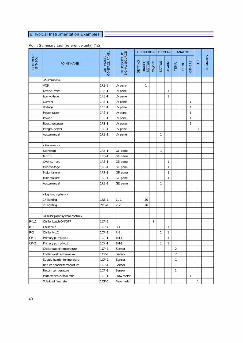
7/23/2019 BMS Design Guide
http://slidepdf.com/reader/full/bms-design-guide 51/90
49
6. Typical Instrumentation Examples
Point Summary Li st (reference only) (1/2)
OPERATION DISPLAY ANALOG
S E T T I N G
O N / O F F ,
S T A T U S
O N / O F F
S T A T U S
A L A R M
T E M P .
H U M I .
O T H E R S
<Substation>
VCB 1RS-1 LV panel 1
Over current 1RS-1 LV panel 1
Low voltage 1RS-1 LV panel 1
Current 1RS-1 LV panel 1
Voltage 1RS-1 LV panel 1
Power factor 1RS-1 LV panel 1
Power 1RS-1 LV panel 1
Reactive power 1RS-1 LV panel 1
Integral power 1RS-1 LV panel 1
Auto/manual 1RS-1 LV panel 1
<Generator>
Start/stop 1RS-1 GE panel 1
MCCB 1RS-1 GE panel 1
Over current 1RS-1 GE panel 1
Over voltage 1RS-1 GE panel 1
Major failure 1RS-1 GE panel 1
Minor failure 1RS-1 GE panel 1
Auto/manual 1RS-1 GE panel 1
<Lighting system>
1F lighting 1RS-1 1L-1 20
2F lighting 2RS-1 2L-1 20
<Chiller plant system control>
R-1,2 Chiller batch ON/OFF 1CP-1 1
R-1 Chiller No.1 1CP-1 R-1 1 1
R-2 Chiller No.2 1CP-1 R-2 1 1
CP-1 Primary pump No.1 1CP-1 1M-1 1 1
CP-2 Primary pump No.2 1CP-1 1M-1 1 1
Chiller outlet temperature 1CP-1 Sensor 2
Chiller inlet temperature 1CP-1 Sensor 2
Supply header temperature 1CP-1 Sensor 1
Return header temperature 1CP-1 Sensor 1
Return temperature 1CP-1 Sensor 1
Instantaneous flow rate 1CP-1 Flow meter 1
Totalized flow rate 1CP-1 Flow meter 1
I N P U T / O U T
P U T
S I G N A L S O U R C E
A U T O M A
T I C
C O N T R O L P
A N E L
E Q U I P M E N T
S Y M B O
L
POINT NAME T O T
R E M A R
K S

7/23/2019 BMS Design Guide
http://slidepdf.com/reader/full/bms-design-guide 52/90
50
6. Typical Instrumentation Examples
Point Summary Li st (reference only) (2/2)
<Outdoor air handling unit control>
OHU-1 Outdoor air handling unit (1F) 1CP-2 1M-2 1 1
Supply air temperature 1CP-2 Sensor 1 1
Supply air dew point temperature 1CP-2 Sensor 1 1
Outdoor air duct temperature 1CP-2 Sensor 1 1
Filter alarm 1CP-2 Sensor 1
Humidification valve defect 1CP-2 Sensor 1
OHU-2 Outdoor air handling unit (2F) 2CP-1 2M-1 1 1
Supply air temperature 2CP-1 Sensor 1 1
Supply air dew point temperature 2CP-1 Sensor 1 1
Outdoor air duct temperature 2CP-1 Sensor 1 1
Filter alarm 2CP-1 Sensor 1
Humidification valve defect 2CP-1 Sensor 1
<Air handling unit control>
AHU-1 Air handling unit (1F hall) 1CP-2 1M-3 1 1
Return air fan 1CP-2 1M-3 1 1
Supply air temperature 1CP-2 Sensor 1 1
Return air humidity 1CP-2 Sensor 1 1
Return air temperature 1CP-2 Sensor 1
CO2 concentration 1CP-2 Sensor 1 1
Supply air fan VSD speed 1CP-2 1M-3 1
Return air fan VSD speed 1CP-2 1M-3 1
Room temperature 1CP-2 Sensor 5 5
Filter alarm 1CP-2 Sensor 1
Humidification valve defect 1CP-2 Sensor 1
VAV 1CP-2 DDCV 10 10
<Fan coil unit control>
Fan coil unit (1F) 1CP-2 DDCF 10
Room temperature (1F) 1CP-2 DDCF 10
Fan coil unit (2F) 1CP-2 DDCF 10
Room temperature (2F) 1CP-2 DDCF 10
<Measurement>
Outdoor air temperature and humidity 2CP-1 Sensor 1 1
OPERATION DISPLAY ANALOG
S E T T I N G
O N / O F F ,
S T A T U S
O N / O F F
S T A T U S
A L A R M
T E M P .
H U M I .
O T H E R S
I N P U T / O U T
P U T
S I G N A L S O U R C E
A U T O M A T I C
C O N T R O L P
A N E L
E Q U I P M E
N T
S Y M B O
L
POINT NAME T O T
R E M A R
K S
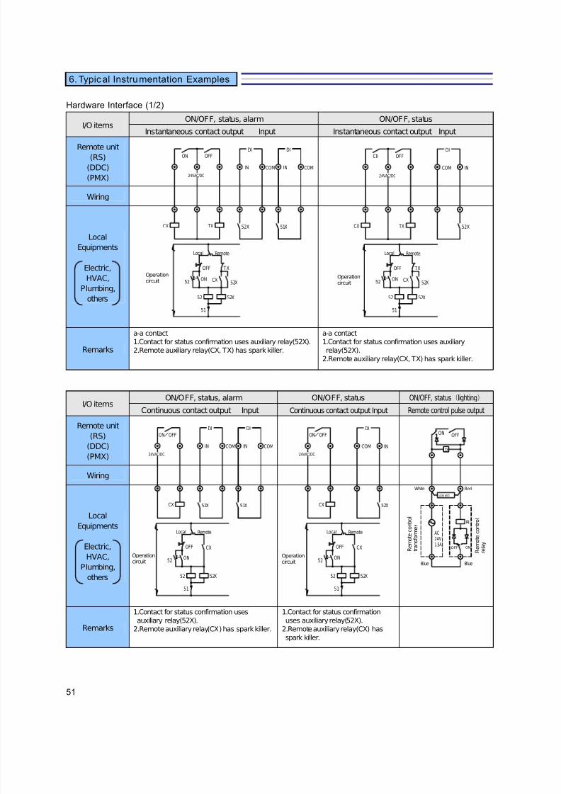
7/23/2019 BMS Design Guide
http://slidepdf.com/reader/full/bms-design-guide 53/90
51
6. Typical Instrumentation Examples
Hardware Interface (1/2)
I/O itemsON/OFF, status, alarm ON/OFF, status
Instantaneous contact output Input Instantaneous contact output Input
Remote unit
(RS)
(DDC)
(PMX)
Wiring
Local
Equipments
Electric,
HVAC,Plumbing,
others
Remarks
a-a contact
1.Contact for status confirmation uses auxiliary relay(52X).
2.Remote auxiliary relay(CX, TX) has spark killer.
a-a contact
1.Contact for status confirmation uses auxiliary
relay(52X).
2.Remote auxiliary relay(CX, TX) has spark killer.
I/O itemsON/OFF, status, alarm ON/OFF, status ON/OFF, status(lighting)
Continuous contact output Input Continuous contact output Input Remote control pulse output
Remote unit
(RS)
(DDC)
(PMX)
Wiring
Local
Equipments
Electric,
HVAC,Plumbing,
others
Remarks
1.Contact for status confirmation uses
auxiliary relay(52X).
2.Remote auxiliary relay(CX) has spark killer.
1.Contact for status confirmation
uses auxiliary relay(52X).
2.Remote auxiliary relay(CX) has
spark killer.
Operationcircuit
24VAC/DC
CX
ON OFF
TX 52X
IN COM
DI
52
OFF TX
52X
RemoteLocal
52X52
51
ON CX
51X
COM
DI
IN
Operationcircuit
24VAC/DC
CX
ON OFF
TX
IN
52X
COM
DI
52
OFF TX
52X
52X52
51
ON CX
RemoteLocal
Operationcircuit
24VAC/DC
CX
ON OFF
52
OFF
52X52
51
ON
CX
52X
IN COM
DI
51X
COM
DI
IN
RemoteLocal
Operationcircuit
24VAC/DC
CX
ON OFF
IN
52X
COM
DI
52
OFF
52X52
51
ON
CX
RemoteLocal
BlueBlue
RedWhite
ON OFF
DI
Locals witch
OFF ON
AC24V1.5A
R e m o t e c o n t r o l
t r a n s f o r m e
R e m o t e c o n t r o l
r e l a y

7/23/2019 BMS Design Guide
http://slidepdf.com/reader/full/bms-design-guide 54/90
52
6. Typical Instrumentation Examples
Hardware Interface (2/2)
I/O itemsStatus, alarm Status Alarm TOT(pulse) input TOT(pulse) input
Contact input Contact input Contact input No-voltage contact pulse No-voltage contact pulse
Remote unit
(RS)
(DDC)
(PMX)
Wiring
Local
Equipments
Electric,
HVAC,
Plumbing,
others
Totalizing
1.Input
12VDC, 10mA
2.Input condition
ON time over 30ms
OFF time over 30ms
ON+OFF time over
100ms
OFF
ON
Totalizing(for water
meter)
1.Input
12VDC, 10mA
2.Input condition
ON time over 30ms
OFF time over 30ms
ON+OFF time over
100ms
OFF
ON
Remarks
1.Input
No-voltage a continuous
contact
2.Circuit voltage, current
DC12V, 10mA
1.Input
No-voltage a continuous contact
2.Circuit voltage, current
DC12V, 10mA
I/O itemsAI AI AI AO
Temperature input Current Input Voltage input Current Output
Remote unit
(RS)
(DDC)
(PMX)
Wiring
Local
Equipments
Electric,
HVAC,
Plumbing,
others
Remarks
1.Input
Pt100Ω, JPt100Ω
2.Circuit voltage, current
DC1V, 1mA
3.Range
0~50℃, -50~100°C
-20~80℃, 50~200℃
1.Input
DC4~20mA
2.Input impedance
300Ω
3.No isolation
1.AIV1 input
1~5VDC
Input impedance 500Ω
2.AIV2 input
0~5VDC
Input impedance 5K Ω
3.AIV3 input
-5~5VDC
Input impedance 110K Ω
4.No isolation
1.Output signal
4~20mA DC
2.Output voltage
24V DC
3.Max. resistance
600Ω
4.With isolator
Status contactAlarm contact
52X
IN COM
DI
51X
COM
DI
IN COM IN
TOT TOT
Pt100Ω resistance
IN
52X
COM
DI
Status contact
IN
51X
COM
DI
Alarm contact
over 30msover 30ms
over 100ms
over 30msover 30ms
over 100ms
Transducer Transmitter 4~20mA
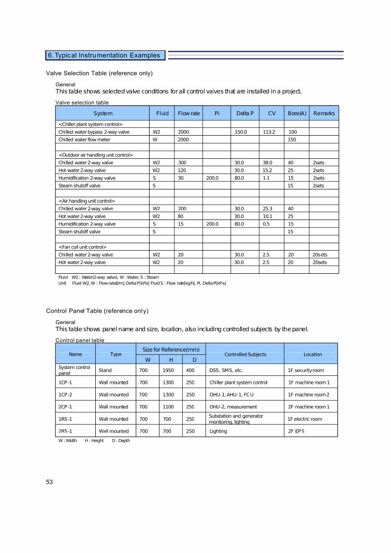
7/23/2019 BMS Design Guide
http://slidepdf.com/reader/full/bms-design-guide 55/90
53
6. Typical Instrumentation Examples
Valve Selection Table (reference only)
General
This table shows selected valve conditions for all control valves that are installed in a project.
Valve selection table
System Fluid Flow rate Pi Delta P CV Bore(A) Remarks
<Chiller plant system control>
Chilled water bypass 2-way valve W2 2000 150.0 113.2 100
Chilled water flow meter W 2000 150
<Outdoor air handling unit control>
Chilled water 2-way valve W2 300 30.0 38.0 40 2sets
Hot water 2-way valve W2 120 30.0 15.2 25 2sets
Humidification 2-way valve S 30 200.0 80.0 1.1 15 2sets
Steam shutoff valve S 15 2sets
<Air handling unit control>
Chilled water 2-way valve W2 200 30.0 25.3 40
Hot water 2-way valve W2 80 30.0 10.1 25
Humidification 2-way valve S 15 200.0 80.0 0.5 15
Steam shutoff valve S 15
<Fan coil unit control>
Chilled water 2-way valve W2 20 30.0 2.5 20 20sets
Hot water 2-way valve W2 20 30.0 2.5 20 20sets
Fluid W2 : Water(2-way valve), W : Water, S : Steam
Unit Fluid W2, W : Flow rate[l/m], Delta P[kPa] Fluid S : Flow rate[kg/h], Pi, Delta P[kPa]
Control Panel Table (reference only)
General
This table shows panel name and size, location, also including controlled subjects by the panel.
Control panel table
Size for Reference(mm)
W H D
System control
panelStand 700 1950 400 DSS, SMS, etc. 1F security room
1CP-1 Wall mounted 700 1300 250 Chiller plant system control 1F machine room 1
1CP-2 Wall mounted 700 1300 250 OHU-1, AHU-1, FCU 1F machine room 2
2CP-1 Wall mounted 700 1100 250 OHU-2, measurement 2F machine room 1
1RS-1 Wall mounted 700 700 250Substation and generator
monitoring, lighting1F electric room
2RS-1 Wall mounted 700 700 250 Lighting 2F EPS
W : Width H : Height D : Depth
TypeName Controlled Subjects Location

7/23/2019 BMS Design Guide
http://slidepdf.com/reader/full/bms-design-guide 56/90
Guide Specification
Building Management System
Energy Management SystemSecurity Systemand,Control Devices

7/23/2019 BMS Design Guide
http://slidepdf.com/reader/full/bms-design-guide 57/90
1
Guide Specifications for HVAC
1. GENERAL
Building Management Systems and Instrumentation for HVAC shall
comply with the conditions stated in this specification in terms of Hardware, Software, and its installation, test, and commissioning.
1.1. Scope
A. Supply all hardware and software necessary to meet the specified
project requirements.
B. Supply hardware layouts, connections, control loop configuration ascontrol flow diagrams.
C. Specify the detailed design for all distributed control system input/outputpoints.
D. Design, supply and install all panels, and data communication networkcables including all hardware.
E. Supply and install all interconnecting cables between control panels,controllers, operator terminals and peripheral devices.
F. Prepare entire specifications for all items supplied by the supplier fromother purchased products.
G. Supply supervisory specialists and engineers at the project site to assistin any phases of system installation, start-up, test and commissioning.
H. Prepare necessary operator and technician training programs
I. Prepare as-built documentation, software, all DDC control logic and all
associated support documentation on approved media which accuratelyrepresents the final system.
1.2. Submittals
System supplier shall submit system control sequence drawings withengineering design to the project.
System configuration diagrams.
Input/Output point and alarm point list.
All system wirings and interconnections between components.
Hardware specifications and instructions, Software specifications, andapplication user guides.
7/23/2019 BMS Design Guide
http://slidepdf.com/reader/full/bms-design-guide 58/90
2
Guide Specifications for HVAC
1.3. References
The latest standards as stated below are followed as references.
ASHRAE American Society of Heating, Refrigerating and Air
Conditioning Engineers
European CE Mark: EMC Directive 2004/108/EC and 89/336/EEC
1.4. Warranty
Warranty shall include all costs for labor, parts, transportations,expenses within one year from actual completion and acceptance by theowner Warranty shall cover.
7/23/2019 BMS Design Guide
http://slidepdf.com/reader/full/bms-design-guide 59/90
3
Guide Specifications for HVAC
2. PRODUCTS
2.1. HARDWARE REQUIREMENTS
2.1.1. General
A Building Management System (BMS) shall be built on a server-clienttype system architecture. All necessary information and systemdatabase are archived in system servers. A PC with web-browsingsoftware installed shall perform as a Client PC, solely for browsing thecontents of all archived data as a supervisory terminal. BMS shall usethe latest technologies such as IP/Linux/XML/ SVG/J AVA as its platform.
2.1.2. Server
System Servers shall comprise of several servers on server-client
system structure. The number of system servers shall differ dependingon the system requirements. Servers shall include Server for SystemManagement and Server for Data Storage. Servers shall be built on thefull open platform using Linux system.
2.1.2.1. Server for System Management
A Server for System Management shall carry out distribution of information for the display, setting, and operations of the managementinformation of the overall system (data point, program, etc.) through theWeb browsing software installed in the Client PC. Server shall support
access of up to 5 client PCs simultaneously.Server shall be provided with dedicated hardware using full openplatform Linux system and come with 32 bit CPU with main storagecapacity of SDRAM 256 MB. Auxiliary memory unit HDD shall be 40GB in 2.5 inch size. Maximum BACnet objects manageable shall be30,000 objects. Server shall back up data up to 72 hours.
2.1.2.2. Server for Data Storage
A Server for Data Storage shall store necessary database for BMS. Theserver shall manage the data transmitted from an Advanced Building
Controller as BMS databases and provide the data to display or print thehistorical trending graphs as well as daily, monthly, and yearly reports.
Server shall be provided with dedicated hardware using full openplatform Linux system and come with 32 bit CPU with main storagecapacity of SDRAM 256 MB. Auxiliary memory unit HDD shall be 40GB in 2.5 inch size. Maximum BACnet objects manageable shall be30,000 objects. Server shall back up data up to 72 hours.

7/23/2019 BMS Design Guide
http://slidepdf.com/reader/full/bms-design-guide 60/90
4
Guide Specifications for HVAC
2.1.2.3 Server for Energy Management
A Server for Energy Management shall store necessary database for thepurpose of energy consumption management.
2.1.2.4 Server for Security Data
A Server for Security Data store necessary database for the purpose of security.
The server shall have the storage capacity of 1 million access history.
Server for Security Data shall comply with the specifications as follows:
- OS: Windows®XP
- Internet Browser: Internet Explorer 6 or later
- CPU: Pentium® IV processor, 3 GHz and above
- Main storage capacity: 512MB and above- Loading function: IPv6, J ava®vm 1.4 and above, XGA,
Acrobat®Reader, IE6.0 and above
- HDD capacity: 40GB and above.
- CD-ROM: 1 unit
2.1.3. Server Redundancy
System Servers shall be capable of dual-redundant system.Dual-redundancy shall be configured by setting 2 servers respectively
with one to one warm-standby system. The system runs 2 serverssimultaneously and when trouble occurred on either one server, anotherone will backup immediately.
Servers carry out the backup of critical data such as Monitoring Data andHistorical data. When trouble occurred below measures shall beapplied to backup data.
Assume there are 2 servers “Server A” and “Server B”. When “ServerA” information cannot be browsed from Client PC due to the networktrouble, it is judged as “Server A: Down”, and then “Server B” (normally
Standby) becomes Active, and the Client PC connection is switched to“Server B” automatically.
When network trouble is solved and “Server A” is restored, (Client PC isrestored to be able to browse server information), as “Server A: Active”,automatically carry out restorations (acquiring trending data during
“Server A” is down from Advanced Building Controller and copying thedifference between Client PC settings and data for scheduled copy).
After restored as “Server A: Active”, Client PC still maintain theconnection to Server B. Operator has to re-login to switch theconnection to Server A.

7/23/2019 BMS Design Guide
http://slidepdf.com/reader/full/bms-design-guide 61/90
5
Guide Specifications for HVAC
2.1.4. Client PC
A Client PC shall be the PC with web-browsing software for accessingthe database achieved and stored in System Servers. Client PC is
basically installed in the supervision room to supervise the wholebuilding. It supervises the following features:
- Monitoring: status, alarms, and measurement of each facility
- Operation: remote ON/OFF control
- Data output: operating status, alarm status, and measuring data
- Data analysis: operating status, alarm status, and measuring data
Up to 5 Client PCs shall be able to access Server simultaneously.
Client PC shall comply with the specifications as follows:
- OS: Windows®XP/Vista
- Internet Browser: Internet Explorer 6 or later
- CPU: Pentium® IV processor, 3 GHz and above
- Main storage capacity: 512MB and above
- Loading function: IPv6, J ava®vm 1.4 and above, XGA,
Acrobat®Reader, IE6.0 and above
2.1.5. Printer
Any type of printer with USB connection available shall be able toconnect the network of the system. Printer driver shall be compatiblewith Windows XP or later.
2.1.6. Communication Network
BMS shall have the capability of full system integration using BACnet IP,LonTalk, Modbus, or OPC.
For the communication network between Client PCs and each server,hyper text transfer protocol (http) shall be used.
Uses BACnet IP between each system server and advanced buildingcontroller.
Internet Protocol version 4 (IPv4) or Internet Protocol version 6 (IPv6)shall be selectable for both communication network depending on therequired specifications.
LonTalk protocol shall be used for the communication betweenAdvanced Building Controller and the DDC controllers, such asmulti-purpose controller.
MODBUS protocol shall be used for the network connection with powermeters and controllers using RS485 communications.
OPC shall be used for the system integration with IBMS. Using PCbased OPC server, BMS shall be able to connect with other systems as
7/23/2019 BMS Design Guide
http://slidepdf.com/reader/full/bms-design-guide 62/90
6
Guide Specifications for HVAC
IBMS by converting BACnet protocol to the one communicable via OPC.
2.1.7. Controller
2.1.7.1. Advanced Bui lding Controller
An Advanced Building Controller shall consolidates the DDC groups andperforms different types of integrated control including energy saving.
The controller shall be capable of autonomous distributed control to
continue the operation even if another part of the system is shut down.
Collects various management information from the DDCs and transmitsinformation to Server for System Management. Stores the collecteddata for forty-eight (48) hours.
The controller shall come with 32 bit CPU with main storage capacity of SDRAM 128 MB and Compact Flash® 64MB. Maximum Data pointsmanageable shall be 1,000 points.
Uses IP (Ethernet® 10 BASE-T/100BASE-TX) 1 channel tocommunicate with the higher level of the system. The communicationline of controllers consists of LonTalk®protocol Controller bus) 4 lines (2
channels). This controller shall back up the data up to 72 hours.
2.1.7.2. Direct Digital Controller (DDC)
DDC controller shall carry out the controls for each and every device. The control operations shall be self-sustaining to enable the continuous
control even if the other parts of the system are down. Datatransmission shall be made via the Client PC and the Advanced BuildingController. The Client PC will receive, for example, the changes insetup values, and send back the data of control results.
DDC lineups several types as follows:
A. Multi -purpose Control ler
the controller designed as a multipurpose controller for several devices.Consists of a basic unit and connectable I/O modules. The number andtypes of the modules shall be flexibly changeable corresponding to the
control or management to fit in various applications.
B. AHU Contro ller
the DDC controller specially designed for AHU control. The controller
has inputs and outputs suitable for AHU control and its software shall befreely editable in response to the applications.
C. I/O Modules
7/23/2019 BMS Design Guide
http://slidepdf.com/reader/full/bms-design-guide 63/90
7
Guide Specifications for HVAC
I/O modules consist of the following types:
- Module with 8 digital inputs
- Module with 16 digital inputs
- Module with 8 relay outputs- Module with 16 relay outputs
- Module with 8 relay outputs + 8 digital inputs
- Module with 4 remote control relay outputs
- Module with 4 totalizer pulse inputs
- Module with 16 totalizer pulse inputs
- Module with 2 voltage/current outputs
- Module with 4 voltage/current outputs
- Module with 4 voltage/current inputs
- Module with 4 temperature inputs
- Module with 2 voltage/current inputs + 2 temperature inputs
- Module with 1 modutrol motor outputs
- Module with 3 modutrol motor outputs
D. Zone Manager
A Zone Manager shall carry out the management of VAV controllers, FanCoil Unit Controllers, and AHU Controllers. Up to 50 controllers are
manageable by one unit of Zone Manager.
E. VAV Controller designed specifically for Variable Air Volume unit control. The VAVcontroller shall be provided as a damper actuator with DDC controllerinside that controls a VAV unit in a building HVAC system. Ratedtorque of VAV damper actuator shall be selectable from 5Nm of 10Nmdepending on the torque required.
F. Fan Coil Unit Controller
provides digital control of fan coil units. In addition to start/stopoperation, valve control, and fan speed changeover, the controller shall
provide setback and interlock operations with outdoor air handler.
2.1.7.3. Chiller Plant Control Packaged Controller
Chiller Plant Control Packaged Controller is a direct digital controller(DDC) specifically designed for sequential control of chiller plantequipment of building HVAC systems. These packaged controllerscomprise of 2 types; a pump controller and a chiller controller. Each
packaged controller consists of a combination of a control module, abase module, I/O modules, and a LCD operator interface.
7/23/2019 BMS Design Guide
http://slidepdf.com/reader/full/bms-design-guide 64/90
8
Guide Specifications for HVAC
The Control module performs arithmetic operations and exerts thechiller/pump controls.
The plug-in type I/O modules are the input/output sections of the
controller and load communications to connect with the control module. The Base module enables power supply and communication interface tothe I/O modules. I/O modules include the followings:
- Module with 4-20 mA DC current inputs
- Module with 4-20 mA DC current output
- Module with one floating output with nominal 135ohm feedbackpotentiometer
- Module with five potential free contact inputs
- Module with four potential free contact (normally open) outputs
- Module with two potential free contact inputs and one 24VDC voltage
instantaneous contact output The Base module supplies power to I/O modules and carries out
communication connections and address settings for I/O modules. Thebase module also functions as a terminal block for the I/O modules.
The I/O modules shall be plug-in type, which can be plugged directly intothe base module back panel and can be easily detached withoutdisconnecting their wiring.
The LCD Operator Interface is a display setting device having a colortouch-panel LCD. Users shall be controlled with access levels andpasswords. This interface shall also be used as a parameter-settingdevice by service personnel.
2.1.7.4. Access Controller
Provide control device for access control equipment of the securitysystem. The controller collects data on access control, monitorsoperating status of access control equipment, and interfaces with otherfacilities such as lighting and air conditioning facilities.
This device shall use Wiegand protocol for the control of Security carddevices.
The controller shall be connectable to the security system via 10BASE-T or 100 BASE-T of Ethernet protocol. Sends access controldata to the system, receives commands from the terminal devices aswell as from the system to control electric lock, and thus performssecurity management of a whole building.
The controller composed of a basic module and I/O modules such asModules for Wiegand signal, power supply for electric keys, passivesensors and other devices,

7/23/2019 BMS Design Guide
http://slidepdf.com/reader/full/bms-design-guide 65/90
9
Guide Specifications for HVAC
2.1.9. Field Devices
2.1.9.1. Sensors
Supplier shall provide the following types of sensor depending on the
specific system requirement.
A. Room Temperature Sensor
Uses resistance thermometer sensor for temperature sensing element.
Designed suitable for room temperature sensing. The sensing rangeshall be from 0°C to 60°C with ±0.3°C sensing accuracy.
B. Duct Insertion Type Temperature Sensor
Uses filterless probe resistance thermometer sensor for temperaturesensing element.
Designed to be installed to air ducts and suitable for supply or return airtemperature detection. The sensing range shall be from 0°C to 60°C
with ±0.3°C sensing accuracy.
Sensor housing shall be dust-proof and splash-proof (IP54) for higherenvironmental resistance and installable using dedicatedquick-detachable bracket for easy installation.
C. Pipe Mount Type Temperature Sensor
Uses resistance thermometer sensor for temperature sensing element.
Detects water temperature of piping. Sensing range of the sensor shall
be from -50°C to 200°C with sensing accuracy of ± 0.05 + 0.002temperature measured.
D. Ceiling Mount Type Temperature Sensor
Uses resistance thermometer sensor for temperature sensing element.
Designed to be installed to narrow opening of ceiling. The sensingrange shall be from 0°C to 60°C with ±0.3°C sensing accuracy.
E. Room Type Humidi ty Transmitter
Uses polymer capacitive humidity sensor for humidity sensing element. The sensing range shall be 0%RH to 100%RH with ± 3% sensingaccuracy. Designed suitable for room humidity detection.
F. Duct Insertion Type Humidi ty Transmitter
Uses polymer capacitive humidity sensor for humidity sensing element. The sensing range shall be 0%RH to 100%RH with ± 3% sensingaccuracy. Designed to be installed on air ducts and suitable for supplyor return air humidity detection.
7/23/2019 BMS Design Guide
http://slidepdf.com/reader/full/bms-design-guide 66/90
10
Guide Specifications for HVAC
Sensor housing shall be dust-proof and splash-proof (IP54) for higherenvironmental resistance and installable using dedicatedquick-detachable bracket for easy installation.
G. Ceiling Mount Type Humidi ty Transmitter
Uses polymer capacitive humidity sensor for humidity sensing element. The sensing range shall be 0%RH to 100%RH with ± 3% sensingaccuracy. Designed to be installed to narrow opening of ceiling.
H. Dew-point Temperature Sensor
uses a polymer capative humidity sensor for a dew point sensingelement. Comes either with or without built-in temperature sensingelement. The sensing range is from -40°C to 60°C DP with ± 1°C
sensing accuracy.Sensor housing shall be dust-proof and splash-proof (IP54) for higherenvironmental resistance and installable using dedicatedquick-detachable bracket for easy installation.
I. Radiant Temperature Sensor
measures infrared radiation at the perimeter on a wall. The sensingrange shall be from 5°C to 50°C with ±2°C sensing accuracy. Outputsignal shall be 1 to 5 V DC. Uses 1 to 5 V DC as output signal linearlycorresponding to 5°C to 50°C.
J. Carbon Monoxide (CO) Concentration Transmitter
detects concentration of Carbon Monoxide and sends a real time value.
The sensing range shall be 0 to 60 ppm with sensing accuracy of ±5%FS. Uses 4 to 20mA signal as output signal linearly corresponding to 0to 60 ppm.
K. Duct Insertion Type Carbon Dioxicide (CO2) Concentration
Transmitter
detects the concentration of CO2 in ducts and other sites using
Non-dispersive infrared absorption method and transmits a real timevalue to other devices. The sensing range shall be 0 to 2000 ppm withsensing accuracy of ±(50 ppm + 5% readout). Uses 1 to 5 VDC signalas output signal linearly corresponding to 0 to 2000 ppm.
The transmitter shall be installable using simple mounting bracket foreasy installation.
The device shall be able to calibrate using CO2 service bag containingCO2 zero gas supply.
7/23/2019 BMS Design Guide
http://slidepdf.com/reader/full/bms-design-guide 67/90
11
Guide Specifications for HVAC
L. PMV Sensor
detects the combination of air temperature, mean radiant temperature,and air velocity and converts into the sensor signal by equipped
processor. The sensing accuracy shall be ±0.5 PMV.
M. Differential Pressure Transmitter
uses silicon diaphragm for its sensing element. Detects deflection of itsdiaphragm as electrical capacitance. The sensing accuracy shall be ±1.0% of full span. Uses 4 to 20mA signal as output signal.
N. Pressure Transmitter
detects the pressure of chilled/hot water, brine, lubricating oil, steam, air,and other fluids. Converts measured values into 4 to 20 mA DC electric
signals.
2.1.9.2. User Terminal Devices
User terminal shall have a temperature sensing element built-in andfunctions as a sensor and a remote controller. User can set On/Off control of devices, temperature setting, and other controls of airconditioning equipment. LCD display will indicate the status of equipment and setting value and present value of temperature.
Use modular connectors for easy installation. This device shall beconnectable to DDC controllers such as Fan Coil Controller, VAV unit
controller, and AHU controller.
2.1.9.3. Electric Actuators and Control Valves
A. Electr ic Valve Actuator
Actuators for motorized control valve shall support several controlsignals as follows;
- Nominal 135 ohm feedback potentiometer
- Nominal resistance 135 ohm input
- 4 mA DC to 20 mA DC input
- 2 V DC to 10 V DC input
B. Contro l Valve
Supplier shall provide the Control valve with the body materials as stated
below;
- FC200: Gray cast iron
- SCS13A: Stainless steel
- FCD450: Ductile cast iron

7/23/2019 BMS Design Guide
http://slidepdf.com/reader/full/bms-design-guide 68/90
12
Guide Specifications for HVAC
Diameter nominal size shall range from DN15 to DN150.
C. Motori zed Control Valve
Provide the valve which electric actuator and its valve body shall beintegrated in a single unit.
D. Motorized Control Valve with Flow Measurement and Control
Functions
Provide the valve which electric actuator and its valve body shall beintegrated in a single unit.
The control valve shall control flow rate not by valve opening but by flowrate calculated by the measured value from built-in pressure sensor andCv.
The control valve comes with built-in pressure sensor and temperaturesensor. The built-in pressure sensor ranges from 0 to 10 MPa at theaccuracy of ±0.1% FS for 7-17°C or 45-65°C and ±0.5% FS for other
conditions. The built-in temperature sensor ranges from 0 to 100°C atthe accuracy of ±1°C.
E. Electric Damper Actuator:
A motorized actuator to open and close a damper. The actuator isprovided on and off control or floating control in response to a commandfrom a controller. Combined with an auxiliary potentiometer will enable
the actuator proportional control in response to a command from aproportional controller.
The damper actuator shall have the torque at the rated voltage of 20Nm
and holding torque of 16Nm.
Operating time is approximately 15 seconds.
F. Electric Damper Actuator:
A motorized actuator to open and close a damper. The actuator isprovided on and off control or floating control in response to a commandfrom a controller. Combined with an auxiliary potentiometer will enable
7/23/2019 BMS Design Guide
http://slidepdf.com/reader/full/bms-design-guide 69/90
13
Guide Specifications for HVAC
2.2. SOFTWARE REQUIREMENTS
2.2.1. Software Requirements for BMS
BMS shall include the application software for management, monitoring,and controls.
2.2.2. User Management
System shall be secured its access by user IDs and passwords. UserManagement function shall be the one manages the passwords anduser IDs. Administrator shall be able to set the access rights of bothbrowsing and operation for each function and the point operation level
according to the user ID.
This function shall be able to register up to 200 user IDs. Normally,
user authentification shall be performed by user ID and password.User shall also be authentificated by registering the IP address of ClientPC. It is possible to set up to 4 client PCs for 1 user ID. Passwordshall be able to set within 36 alphanumeric characters. User shall beable to change the password anytime.
Screen access rights to display and operate shall be set by user.Operation level, alarm, and buzzer shall be able to set by segregation.
2.2.2.1. Log Output
Records and displays all the operating logs carried out by user in list.
Items to be recorded and displayed are:- Date (YYYY/MM/DD) at the time of operation
- Time (hours, minutes, and seconds) at the time of operation
- IP address of Client PC
- User ID
Operation type such as displaying, setting, printing, change of display,and canceling, button name to be clicked, dialog box name to be opened,contents of operation,
contents of inputs and setting, device ID, point ID, point name, programname, and operation failed or not.
Maximum storable logs are up to 1,000,000 logs. Operation logs shallbe able to output in CSV file format and save in Client PC.
2.2.3. Graphic
Displays the status of each facility targeted for management in graphicformats such as floor plan, cross section and schematic diagram. Useris possible to perform the equipment's ON/OFF operation and setpointchange operation, and to display the trending graph and individual
7/23/2019 BMS Design Guide
http://slidepdf.com/reader/full/bms-design-guide 70/90
14
Guide Specifications for HVAC
equipment schedule.
The graphic displays present the status of each piece of equipment to becontrolled in graphical forms such as floor plans, cross sections or
schematic diagrams. Starts/stops equipment, changes setting, displayshistorical trend and individual equipment schedule. The displays can beenlarged and reduced at a desired magnification using SVG supportingmagnification at browser. Up to 1,000 graphical displays can beassigned to the system.
A dynamic element placed on a static element of equipment or floorindicates the status of a point by changing the color of the symbol ordisplaying the numerical value of analog/totalizer point. The dynamicelement can also lead operators to another graphic display. Up to 200dynamic elements can be displayed on a screen.
The types of dynamic elements (points + screen transition) are shown
below:
- Digital color change
- Digital shape change
- Analog numerical value display
- Animation
- Live wire display
- Graphic display selection
- Screen call
- Screen transition
- Picture scanner read display
User shall be able to modify or revise the graphic using GraphicGenerator software which generates user-defined graphics and givesfacility to edit the screen in the event of any change in the applicationenvironment such as partition or room name of the building.
2.2.4. Group List
Lists groups for the user to manage the Points easily. In addition to the
system group list that is already listed, there is the user group list thatcan be set by the user optionally.
It is possible to carry out batch ON/OFF command and batch settingschange for each group. Servers shall have a capability of redundantsystem.
2.2.5. Alarm
If any alarm occurs, the system automatically processes the alarm. The system notifies the alarm via buzzer sounds. BMS shall displaythe latest alarm and brink indicators. The operation of the latest alarm
7/23/2019 BMS Design Guide
http://slidepdf.com/reader/full/bms-design-guide 71/90
15
Guide Specifications for HVAC
display, buzzer sounds and the Alarm Dashboard can be specified bythe segregation pattern of the Segregation setting. Four types of alarmsounds are available for each alarm level.
The following alarm events are available.<Points>
- Alarm input
- Unmatched command (Failure of start/stop of start/stop points, status- unmatched)
- Analog high/low limit alarm
- Sensor error
- Trouble
- Totalized value increase error
- Control alarm (Power demand target value exceeded, etc.)
<System>
- Component alarm (bus trouble, line status, error, remote unit noresponse)
- Power demand alarm, power failure alarm, fire alarm
Specify the following alarm level for each alarm point.
- Emergency alarm
- Major alarm
- Moderate alarm
- Minor alarm
2.2.5.1. Alarm Dashboard
Displays the information about change of status and alarm occurrence
traditionally printed on a message printer. Only the requiredinformation can be extracted and displayed by narrowing search toall/alarm/operation setting/unacknowledged alarm records or searchinginformation by a desired text string. Comments can also be entered if any. The accumulated data can be saved to the desired media (harddisk/USB memory, etc.) of a Client PC in a CSV format file. The datashall be displayed in PDF file to realize paper-less operations.
The information displayed on the Alarm Dashboard is as follows:
- Point alarm
- Control alarm
- Device alarm
- Remote unit alarm
- Point operation
- Point change of status
7/23/2019 BMS Design Guide
http://slidepdf.com/reader/full/bms-design-guide 72/90
16
Guide Specifications for HVAC
When an alarm occurs in logged-in status, the alarm is notified by thebuzzer sound, updated New Alarm display, and indicator blinking based
on the alarm. Also, alarm occurrence and recovery will be recorded inAlarm Dashboard irrespective of login status.
Buzzer sound has kinds of tones in each alarm level. Alarm is alsogiven as an appropriate voice announcement when an alarm occurs.
2.2.5.2. Alarm Noti fication via E-mail or SMS
Alarms shall be notified to the PC or mobile terminal of buildingadministrator through E-mail or Short Message Service. Alarmnotification supports alarm confirmation operation in places far awayfrom the client PC.
2.2.6. Device/Remote Unit Status Monitoring
Based on the device/remote unit status monitoring function, the status of system servers, system controllers, and filed controllers is constantlymonitored. Whenever a trouble is found, and alarm is notified with thebuzzer sound, and so on.
2.2.7. Trending
Trending function graphically displays time-series variation in measured
point data such as power and temperature, time series changes of power operation status (ON/OFF), and totalized data are stored for afixed period of time and displayed on trend graph (broken line) and bargraph (bar graph/laminated graph).
User shall also display up to 8 different scales of graph all at once. 4axes each are displayed on both left and right side of the trending graph.
Trend shall be able to display up to 8 points per sheet and 400 sheetsmaximum. Displayable points are ON/OFF, Status, Measured, Setpoint,and Tantalization.
Data of 1 minute cycle shall be able to be displayed for up to 40 days.
Data of 1 hour cycle is stored for the past 13 months. Data of 1 daycycle is stored for the past 10 years. Data of 1 month cycle is stored forthe past 10 years.
Displayable graph types are broken line, bar, laminated, combination of broken line and bar graph, combination of broken line and laminatedgraph.
2.2.7.1. Real Time Trending
7/23/2019 BMS Design Guide
http://slidepdf.com/reader/full/bms-design-guide 73/90
17
Guide Specifications for HVAC
In addition to the trending function, the real time trending shall also beselectable. Collects and stores the data of points that are targeted forreal time data collection, and then displays obtained results as brokenline graph. The latest data shall be collected all the time. Meanwhile,
in “Specific” method, there are two data collection methods, namely amethod to collect the point data when status change has occurred ondigital point and a method to collect the point data by setting starttime/end time. It can be set in either one of these. Collected pointdata shall be displayed as real time trending graph. It shall be able todisplay and print the real time trending graph as numeric data. Thepoints targeted for real time data collection and the information about thecollection conditions set by the user in client PC will be set in real time
data collection file. The real time data collection file reflects theinformation to Server for System Management and Advanced BuildingController through update function.
Minimum data collection cycle for real time trending is 1 second andusual trending collects and displays in 15 minutes interval.
2.2.8. Report
Measured values and totalized values are displayed on the screen, andthe daily report of electricity and air-conditioning operations are prepared.User shall be able to output daily report either automatically or manuallyin PDF format (print image) which realize paper-less operation.
2.2.8.1. Daily Report
Daily reports for the last 40 days including the current day can bedisplayed and printed manually. Daily report displayed on the screencan be output in CSV format as well.
Printable data are the following 3 data.
- Hourly report datacontains 1-minute values totalized for 1 hour (totalized value) ORselected value among; max./min./average value of 1-minute values for1 hour and on-the-hour value (measured value)
- Daily report datacontains 1-hour values totalized for 1 day (for the current day and for
previous day) and load factor (totalized value only) AND max., min.,av., and reading values of 1-hour values for 1 day. (Specify the values
necessary to print.)
- Monthly report datacontains 1-day value totalized for 1 month (to the current day of themonth from the following day of the previous month, to the current dayof the previous month from the following day of the two monthsprevious) and load factor (totalized value only) AND max., min., and av.
values of 1-day values for 1 month. (Specify the values necessary to
7/23/2019 BMS Design Guide
http://slidepdf.com/reader/full/bms-design-guide 74/90
18
Guide Specifications for HVAC
print. Monthly report data is printed out after the daily report data isprinted.)
Monthly report can be output either automatically or manually in PDF
format (print image).
2.2.8.2. Monthly Report
Monthly reports for the last 13 months including the current month canbe displayed and printed manually at your convenience. Monthly report
displayed on the screen can be output in CSV format as well.
Printable data are following 3 data as a monthly report.
- Daily report datacontains 1-hour values totalized for 1 day and load factor (totalizedvalue only) OR selected value among; max./min./average value of
1-hour values for 1 day.
- Monthly report datacontains 1-day values totalized for 1 month (for the current month andfor the previous month) and load factor (totalized value only) ANDmax., min., and av. values of 1-day values for 1 month. (Specify thevalues necessary to print. Monthly report data is printed out after thedaily report data is printed.)
- Yearly report datacontains 1-month values totalized for 1 year (to the current month of the year from the following month of the previous year, to the currentmonth of the previous year from the following month of the two yearsprevious) and load factor (totalized value only) AND max., min., and av.values of 1-month values for 1 year. (Specify the values necessaryto print. Yearly report data is printed out after the monthly report datais printed.)
Yearly report can be output either automatically or manually in PDFformat (print image).
2.2.8.3. Yearly Report
Yearly reports for the last 10 years including the current year can be
displayed and printed manually at your convenience. Yearly reportdisplayed on the screen can be output in CSV format as well.
Printable data are the following 2 data as a yearly report.
- Monthly report datacontains 1-day values totalized for 1 month and load factor (totalizedvalue only) OR selected value among; max./min./average value of 1-day values for 1 month.
- Yearly report datacontains 1-month values totalized for 1 year (for the current year and
7/23/2019 BMS Design Guide
http://slidepdf.com/reader/full/bms-design-guide 75/90
19
Guide Specifications for HVAC
for the previous year) and load factor (totalized value only) AND max.,min., and av. values of 1-month values for 1 year. (Specify the valuesnecessary to print. Yearly report data is printed out after the monthlyreport data is printed.)
2.2.8.4. Editable Report Format
Report format is editable freely by users if required. User shall be ableto change, add and delete ruled lines, and insert merged cell to matchthe requirement of each project. BMS shall switch the report formatwhen locale is changed.
2.2.9. Runtime Monitoring and On/Off Counting
This function shall be used to display the equipment that exceeds acertain value of runtime/on-off cycle count, in the MaintenanceNotification screen, and activates the judgment of equipment inspectionand replacement time.
User shall be able to maintain and replace the equipment in the buildingat regular intervals, prevent the breakdown of the equipment, andthereby control the maintenance cost.
It is possible to generate and displays the PDF file as maintenancemonitoring report with the information of all equipment or the equipmentthat exceeds the monitoring targeted value. The PDF file can beprinted manually anytime using a printer.
Up to 50 groups and 100 points per group shall be monitored andcounted.
This function counts total time and elapsed time up to 999,999 hours.
2.2.10. Overtime Running
Overtime running means the extra running of the equipment based onthe operation requested from the user operable equipment or client PC,in other than the time slot (core time) that is set in advance. Receivingof request, count of actual runtime and printing are carried out in the
overtime running management.
2.2.11. Meter Reading
Automatically collects the overtime runtime data and the meter-readingvalue of meters measuring power, water supply, gas, and so on.Calculates the consumption month wise.
In addition, it detects and modifies abnormal value after meter-readingand outputs the list of meter-reading results.
7/23/2019 BMS Design Guide
http://slidepdf.com/reader/full/bms-design-guide 76/90
20
Guide Specifications for HVAC
Maximum data points available are 3000 meters including 1,500 actualmeters and 1,500 logical meters.
Up to 50 types of Meter shall be assignable. This function handles up
to 400 tenants.Maximum totalization point shall be 1,500 meters. Overtime runtime is1,000 request units maximum.
Automatic meter-reading shall be able to set once a month. Operatorshall read meter manually anytime.
Meter reading record shall be saved in CSV format and output anytime
operator requests.
2.2.12. Time Program Contro l
Automatically starts or stops the equipment at the preset time. For theweekly schedule (that is the base schedule for each day of the weekthroughout the year) and the priority schedule (that can be used forholiday settings, etc.), it is possible to set up to 8 times operation and the
time a day.
Based on the weekly schedule, priority schedule, and calendar*1settings, the execution schedule for the next 1 week from the currentdate can be created for starting or stopping the equipment.
Further, it is possible for the user to specify name for time programs.
Time programs shall be able to display all the on/off time settings of timeprograms in list.
2.2.13. Schedule Composition
Interlocks multiple Time Programs into 1 schedule and write it in aspecified Time Program. It shall be convenient to create a scheduleusing this function based on the time program of each tenant, forcommon utility areas (such as entrance hall) used by many tenants.
Compose up to 10 sub-programs per Advanced Building Controller andup to 10 time programs per sub-program.
2.2.14. Event Program
Automatically performs interlock operation for multiple facilities such asAHU and lighting inside the building, along the predeterminedconditions.
It is possible to take a common emergency action and reduce the load torun each facility by specifying the link and related operation betweenmultiple facilities, such as run pattern/run sequence of facilities andcounter measures during alarm, in advance.

7/23/2019 BMS Design Guide
http://slidepdf.com/reader/full/bms-design-guide 77/90
21
Guide Specifications for HVAC
2.2.15. Energy Saving Appl ications
BMS shall have the applications designed for Energy-saving control.
The applications include control software such as Optimum Start/StopControl, Chiller Optimum Start/Stop Control, Duty Cycle Control, PowerDemand Control, VAV Control, and VWV Control.
2.2.15.1. Optimum Start/Stop Control
This function estimates the attribute of temperature raise/fall for HVACstart/stop and performs the optimum start/stop control of Air Handling
Units to avoid unnecessary runtime. Up to 50 subsystems shall be ableto control under Advanced Building Controller. This function output theoptimum timing of start/stop command based on the time program inwhich measured room temperature and control equipment are assigned.
2.2.15.2. Chiller Optimum Start/Stop Control
This function refers to the estimated optimum start/stop time based onthe optimum start/stop control for AHU, and starts the chiller plant "x"minutes earlier than the optimum start time of the earliest AHU and stopsthe chiller plant "y" minutes earlier than the optimum stop time of thelatest AHU, within the same chiller plant system. Up to 4 types of start/stop holding time shall be able to set per subprogram.
2.2.15.3. Duty Cycle Control
This function calculates the optimum stop time of Packaged AirConditioning units etc. while maintaining a comfortable temperature
environment, and reduces thermal energy/electrical energy byperforming duty cycle control up to 20 subsystems per AdvancedBuilding Controller and up to 20 points per subsystem. This functionstops and recovers the equipment based on the measured roomtemperature.
2.2.15.4. Power Demand Control
This function supports 2 types of power contracts; Actual and Demand,to cover a variety of power contract systems that may differ dependingon countries. Power demand control function estimates the usage of power at intervals, decides the necessity of interruption/recovery, andinterrupts/recovers the equipment according to the capacity required.
BMS stores the power demand control results as history and displaysthe targeted value and demand value.
7/23/2019 BMS Design Guide
http://slidepdf.com/reader/full/bms-design-guide 78/90
22
Guide Specifications for HVAC
Further, it is possible to save the day's data and month's data of powerdemand in the optional media (hard disk, USB memory, etc.) of the clientPC, in CSV format.
2.2.16. Power Failure & Restoration Control
During power failure, if Server for System Management, Server for DataStorage, and Advanced Building Controller are backed up with UPS,alarm notification shall be given through buzzer sound, blinking of thepower failure icon, and new alarm display. During this stage, outputs
except fire process event program output, power failure event output,and output made by manual operation are withheld.
When detecting the startup of the generator, startup is output one by onein the points registered in the generator registration order list. Outputs
other than fire process event program output, power failure event output,and output made by manual operation are withheld.
Power restoration program shall be able to start up when detectingcommercial power restoration. At this time, since output is done forON/OFF point in the same way as before power failure occurrence andalso the output that was withheld during power failure is output, it ispossible to move back automatically to the original status. Selectingautomatic/manual startup and specifying the point order of powerrestoration is possible for power restoration program.
2.2.17. Generator Load Distr ibution Control
When the generator for an emergency purpose is operated during powerfailure, this function keeps the power load. If the instantaneous value of the generator load exceeds the desired value set beforehand, excesspower is cutoff from units in order of low-priority level. On the otherhand if it is low, power is connected to the units in order of priority level.
2.2.18. VAV Control
Provide the VAV control application which optimizes the supply airtemperature and pressure of AHU including VSD control of AHU fan.
The application shall have the function to optimize the pressure loss of duct to reduce energy consumption of fan.
Provide the function that optimizes supply air temperature to satisfy eachzone temperature condition.
2.2.19. VWV Control
VWV stands for Variable Water Volume. This application shall be a partof energy saving applications for heating/cooling source delivery

7/23/2019 BMS Design Guide
http://slidepdf.com/reader/full/bms-design-guide 79/90
23
Guide Specifications for HVAC
systems. VWV shall control the running speed of secondary waterdelivery pumps in Chiller Plant to maintain the supply water pressure incertain level by means of all AHUs’ differential pressure. Enablespower of the delivery pump to be reduced significantly without the
decrease of HVAC performance.
VWV control requires motorized control valve with differential pressuresensor to detect the differential pressures of all AHUs.
VWV control consists of three programs such as demand calculation perprogram, pressure setpoint calculation, and energy saving effectcalculation.
Demand calculation per program calculates the demand level of eachprogram of a maximum of 30 AHUs with the same control level.
Setpoint calculation determines the setpoint change request for chillerplant equipment. The pressure setpoint is calculated based on thesetpoint change request.
Energy saving effect calculation calculates the energy saving effect as a
result of VWV control.
2.2.19. DDC Software
Provide DDC software which freely programmable and modifiable bysystem engineers. System Engineer shall be able to create or modifycontrol software for multipurpose controller through field engineeringtools. By entering necessary parameters and wiring output and input of
each software module, control software for certain HVAC applicationsshall be created.
2.2.20. Chiller Plant Control Packaged Controller
Chiller Plant Control Packaged Controller is a direct digital controller(DDC) specifically designed for sequential control of chiller plantequipment of building HVAC systems. This controller carries outenergy-saving control including the optimization of multiple chillers and
other chiller plant units in response to the air conditioning load. Usercan change the setting of control sequence through operator interface
equipped with the controller. Not only the pre-programmed sequence,but also the user-determined programmed control is also available forChiller plant control.
Operator shall be able to switch automatic/manual operation bycommunicating with host system. Manual operation takes highest
priority for all the control sequences.
Group command is executed by communicating with the host BMS oroperating interface.
Daytime or nighttime mode can be switched by communicating with host

7/23/2019 BMS Design Guide
http://slidepdf.com/reader/full/bms-design-guide 80/90
24
Guide Specifications for HVAC
system. The switchover between daytime and nighttime modeschanges the operating sequences, maximum number of running chillers,and load at startup.
Operator shall be able o switch cooling/heating mode by communicatingwith host BMS or operating interface. The switchover between coolingand heating also changes the operating sequences, maximum numberof running chillers, and load at startup.
Operating sequence has several types such as normal sequence,sequence with base unit changeover, rotation, and operator program.Normal sequence fixes the order of chiller or pump. Sequence withbase unit changeover performs the sequential control but base unit ischanged so as to avoid too much load for base unit.
Rotation mode is a method for averaging each chiller runtime. Theoperating sequence of he chillers are sequentially shifted so that the
chiller which has been stopped for the longest period is started first andthe chiller which has been running for the longest period is stopped first.
Operator shall be able to program the operation sequence. Thismethod is useful when the capacity of chillers or pumps to be controlleddiffers; operator is possible to assign desired sequence.
2.2.21 Software Requirements for Security System
Security System shall include the application software for management,monitoring, and controls.
2.2.22 Room Data Process
Room is considered to be the smallest unit in the building, which issegmented to perform the security status changeover (alert/non alert)and access user management in Security System. Multipleregistrations of data points required for controlling and monitoring shallbe being performed in one room.
In this system, each room is registered in Access Controller, and thenthe controller performs access management control for those rooms.
Consequently, when there are several card readers in a single room,
access management control will be executed simultaneously for all thecard readers in the room. In Figure 1 of “Room setting example”, securitychangeover can be made from either one of the 2 card readers.
2.2.23 Access User Management
Access user management manages the user information that is used foraccessing the buildings and rooms. It includes the operation of userregistration, deletion, display based on various search conditions, settingthe information and copying the attributes.

7/23/2019 BMS Design Guide
http://slidepdf.com/reader/full/bms-design-guide 81/90
25
Guide Specifications for HVAC
User access operation becomes possible by distributing the userinformation created in the center to the remote.
Up to 100,000 users shall be manageable. User information shall
include access information and personal information as stated below.
Access Information
- Department ID
- User No.
- Card data
- Card type
- Registration status
- Entry allowed room/group
- Validity period
- PIN- Close rights
- 1st entry rights
- Last exit rights
- Pass back rights.
Personal Information
- Name
- Nickname
- Division (up to 2 divisions manageable)
- Gender
- Date of Birth
- Age (calculated automatically from the date of birth)
- Notes (up to 5 notes memorable)
2.2.24 Log Output
Records and displays all the operating logs carried out by user in list.Items to be recorded and displayed are:
- Date (YYYY/MM/DD) at the time of operation
- Time (hours, minutes, and seconds) at the time of operation
- IP address of Client PC
- User ID
Operation type such as displaying, setting, printing, change of display,and canceling, button name to be clicked, dialog box name to be opened,contents of operation,
contents of inputs and setting, device ID, point ID, point name, programname, and operation failed or not.

7/23/2019 BMS Design Guide
http://slidepdf.com/reader/full/bms-design-guide 82/90
26
Guide Specifications for HVAC
Maximum storable logs are up to 1,000,000 logs. Operation logs shallbe able to output in CSV file format and save in Client PC.
2.2.25. Graphic
Displays the status of each facility targeted for management in graphicformats such as floor plan, cross section and schematic diagram. Useris possible to perform the equipment's ON/OFF operation and setpointchange operation, and to display the trending graph and individualequipment schedule.
The graphic displays present the status of each piece of equipment to becontrolled in graphical forms such as floor plans, cross sections orschematic diagrams. Starts/stops equipment, changes setting, displayshistorical trend and individual equipment schedule. The displays can be
enlarged and reduced at a desired magnification using SVG supportingmagnification at browser. Up to 1,000 graphical displays can beassigned to the system.
A dynamic element placed on a static element of equipment or floorindicates the status of a point by changing the color of the symbol ordisplaying the numerical value of analog/totalizer point. The dynamicelement can also lead operators to another graphic display. Up to 200dynamic elements can be displayed on a screen.
The types of dynamic elements (points + screen transition) are shownbelow:
- Digital color change
- Digital shape change
- Analog numerical value display
- Animation
- Live wire display
- Graphic display selection
- Screen call
- Screen transition
- Picture scanner read display
User shall be able to modify or revise the graphic using Graphic
Generator software which generates user-defined graphics and givesfacility to edit the screen in the event of any change in the applicationenvironment such as partition or room name of the building.
2.2.26. Group List
Lists groups for the user to manage the Points easily. In addition to thesystem group list that is already listed, there is the user group list thatcan be set by the user optionally.
7/23/2019 BMS Design Guide
http://slidepdf.com/reader/full/bms-design-guide 83/90
27
Guide Specifications for HVAC
It is possible to carry out batch ON/OFF command and batch settingschange for each group. Servers shall have a capability of redundantsystem.
2.2.27. Alarm
If any alarm occurs, the system automatically processes the alarm. The system notifies the alarm via buzzer sounds. BMS shall displaythe latest alarm and brink indicators. The operation of the latest alarmdisplay, buzzer sounds and the Alarm Dashboard can be specified by
the segregation pattern of the Segregation setting. Four types of alarmsounds are available for each alarm level.
The following alarm events are available.
<Points>
- Alarm input
- Unmatched command (Failure of start/stop of start/stop points, status- unmatched)
- Analog high/low limit alarm
- Sensor error
- Trouble
- Totalized value increase error
- Control alarm (Power demand target value exceeded, etc.)
<System>
- Component alarm (bus trouble, line status, error, remote unit noresponse)
- Power demand alarm, power failure alarm, fire alarm
Specify the following alarm level for each alarm point.
- Emergency alarm
- Major alarm
- Moderate alarm
- Minor alarm
2.2.27.1 Security Alarm Dashboard
Displays the information about change of status and alarm occurrencetraditionally printed on a message printer. Only the requiredinformation can be extracted and displayed by narrowing search to
all/alarm/operation setting/unacknowledged alarm records or searchinginformation by a desired text string. Comments can also be entered if any. The accumulated data can be saved to the desired media (harddisk/USB memory, etc.) of a Client PC in a CSV format file. The datashall be displayed in PDF file to realize paper-less operations.

7/23/2019 BMS Design Guide
http://slidepdf.com/reader/full/bms-design-guide 84/90
28
Guide Specifications for HVAC
The information displayed on the Alarm Dashboard is as follows:
- Point alarm
- Control alarm- Device alarm
- Remote unit alarm
- Point operation
- Point change of status
When an alarm occurs in logged-in status, the alarm is notified by thebuzzer sound, updated New Alarm display, and indicator blinking basedon the alarm. Also, alarm occurrence and recovery will be recorded inAlarm Dashboard irrespective of login status.
Buzzer sound has kinds of tones in each alarm level. Alarm is alsogiven as an appropriate voice announcement when an alarm occurs.
2.2.27.2 Alarm Notification via E-mail or SMS
Alarms shall be notified to the PC or mobile terminal of buildingadministrator through E-mail or Short Message Service. Alarmnotification supports alarm confirmation operation in places far awayfrom the client PC.
2.2.28. Device/Remote Unit Status Monitoring
Based on the device/remote unit status monitoring function, the status of system servers, system controllers, and filed controllers is constantlymonitored. Whenever a trouble is found, and alarm is notified with the
buzzer sound, and so on.
2.2.29. Report
Measured values and totalized values are displayed on the screen, andthe daily report of electricity and air-conditioning operations are prepared.User shall be able to output daily report either automatically or manuallyin PDF format (print image) which realize paper-less operation.
2.2.29.1. Daily Report
Daily reports for the last 40 days including the current day can bedisplayed and printed manually. Daily report displayed on the screen
can be output in CSV format as well.
Printable data are the following 3 data.
- Hourly report datacontains 1-minute values totalized for 1 hour (totalized value) OR
7/23/2019 BMS Design Guide
http://slidepdf.com/reader/full/bms-design-guide 85/90
29
Guide Specifications for HVAC
selected value among; max./min./average value of 1-minute values for1 hour and on-the-hour value (measured value)
- Daily report data
contains 1-hour values totalized for 1 day (for the current day and forprevious day) and load factor (totalized value only) AND max., min.,av., and reading values of 1-hour values for 1 day. (Specify the valuesnecessary to print.)
- Monthly report datacontains 1-day value totalized for 1 month (to the current day of the
month from the following day of the previous month, to the current dayof the previous month from the following day of the two monthsprevious) and load factor (totalized value only) AND max., min., and av.values of 1-day values for 1 month. (Specify the values necessary toprint. Monthly report data is printed out after the daily report data is
printed.)Monthly report can be output either automatically or manually in PDFformat (print image).
2.2.29.2. Monthly Report
Monthly reports for the last 13 months including the current month canbe displayed and printed manually at your convenience. Monthly reportdisplayed on the screen can be output in CSV format as well.
Printable data are following 3 data as a monthly report.
- Daily report datacontains 1-hour values totalized for 1 day and load factor (totalizedvalue only) OR selected value among; max./min./average value of 1-hour values for 1 day.
- Monthly report datacontains 1-day values totalized for 1 month (for the current month andfor the previous month) and load factor (totalized value only) ANDmax., min., and av. values of 1-day values for 1 month. (Specify thevalues necessary to print. Monthly report data is printed out after thedaily report data is printed.)
- Yearly report data
contains 1-month values totalized for 1 year (to the current month of the year from the following month of the previous year, to the currentmonth of the previous year from the following month of the two yearsprevious) and load factor (totalized value only) AND max., min., and av.values of 1-month values for 1 year. (Specify the values necessary
to print. Yearly report data is printed out after the monthly report datais printed.)
Yearly report can be output either automatically or manually in PDFformat (print image).

7/23/2019 BMS Design Guide
http://slidepdf.com/reader/full/bms-design-guide 86/90
30
Guide Specifications for HVAC
2.2.29.3. Yearly Report
Yearly reports for the last 10 years including the current year can be
displayed and printed manually at your convenience. Yearly reportdisplayed on the screen can be output in CSV format as well.
Printable data are the following 2 data as a yearly report.
- Monthly report datacontains 1-day values totalized for 1 month and load factor (totalized
value only) OR selected value among; max./min./average value of 1-day values for 1 month.
- Yearly report datacontains 1-month values totalized for 1 year (for the current year andfor the previous year) and load factor (totalized value only) AND max.,
min., and av. values of 1-month values for 1 year. (Specify the valuesnecessary to print. Yearly report data is printed out after the monthly
report data is printed.)
2.2.29.4. Edi table Report Format
Report format is editable freely by users if required. User shall be ableto change, add and delete ruled lines, and insert merged cell to matchthe requirement of each project. BMS shall switch the report formatwhen locale is changed.
2.2.30. Security Card Data Import
Provide the function that imports the security card data items in CSVformat.
- User No.
- Card data
- User Name
- User Nickname
- 2 Divisions of organization
- Gender
- Birthday- 5 Notes
- All room rights
- Rights pattern
- Rights index
- Rights index for area
- Rights index for room
- Close mode privilege
7/23/2019 BMS Design Guide
http://slidepdf.com/reader/full/bms-design-guide 87/90
31
Guide Specifications for HVAC
- 1st entry privilege
- Last exit privilege
- Passback privilege
- State of registration- Start date of valid term
- End date of valid term
- Number of card issue
- Department ID
2.2.31. Security Card Data Export
Provide the function that exports the security card data items in CSVformat.
- User No.- Card data
- User Name
- User Nickname
- 2 Divisions of organization
- Gender
- Birthday
- 5 Notes
- All room rights
- Rights pattern
- Access rights index- Access rights index for area
- Access rights index for room
- Access rights index for room name
- Close mode privilege
- 1st entry privilege
- Last exit privilege
- Passback privilege
- State of registration
- Start date of valid term
- End date of valid term- Number of card issue
- Department ID
- Department Name
2.2.32. Personal Photo Image Import
Provide the function that imports the photo image of card user, and to
display it in the screen. By checking the screen display, it is possible to
7/23/2019 BMS Design Guide
http://slidepdf.com/reader/full/bms-design-guide 88/90
32
Guide Specifications for HVAC
confirm the identity of the card holder in case he or she loses the card,etc. The image data can be imported from the media on to the driveconnected to the client PC in J PEG image. It is possible to specify thesource folder for importing. that exports the security card data items in
CSV format.
2.2.33. Scope Management
Scope management function is used while registering/changing/deletingor referring to records of the access user information for each
department (or tenant). Management range and reference range willbe restricted based on the category setup. In other words, administratorof each department (Tenant) can register, delete, refer to access historyand perform occupant display, etc. towards only access users whosecategories are the same as his or her own category. Accordingly, if login is performed through the administrator ID and password, subsequentoperation and screen display will be automatically restricted by judgingthe category of the administrator who logged in.
2.2.34. Local Ant i-passback Control
Provide the function of Local Anti-passback Control. This function isused to compare the Card Reader type (Entry Reader or Exit Reader)with occupancy status (IN when the entry reader verification is OK andOUT in case of exit reader verification is OK) and perform accessmanagement without any logical discrepancy. With this function, it ispossible to prevent the unauthorized access such as "Card sharing" and"Unauthorized accompanying" and manage the occupancy more strictly.Local Anti-passback Control is the control made on a per-controller basisand it cannot perform logical judgment across rooms. To performcontrols across multiple doors or rooms, use Global Anti-passback.
2.2.35. Global Ant i-passback Control
As a result of card reader operation, Global Anti-passback functionallows the access if the card actually belongs to that particular zone anddisallows the access if it belongs to other zones. In other words, it judges
whether the correct individual is residing in the zone and carries out aproper access management without any logical discrepancy. With thisfunction, it is possible to prevent the unauthorized access such as "Cardsharing" and "Unauthorized accompanying" and manage the occupancymore strictly. Further, trouble such as system communication failure thataffects this control may occur. By considering these cases, it is possibleto set in advance, whether the flexibility or security should be givenimportance like “Allow all users at the time of trouble” or “Emphasize thesecurity even at the time of trouble” in accordance with the operation
7/23/2019 BMS Design Guide
http://slidepdf.com/reader/full/bms-design-guide 89/90
33
Guide Specifications for HVAC
level.
2.3. SYSTEM INTEGRATION
2.3.1. BACnet Conformance
BMS and its components shall comply with BACnet IP as itscommunication protocol for open system integration. System serversshall be able to communicate with third-party BACnet devices.
2.3.2. LonMark Conformance
BMS shall have the product conformance by LonMark International®.Advanced Building Controller communicates with DDCs using LonTalkprotocol.
2.3.3. Modbus
BMS shall be connectable through Modbus protocol. Equipment suchas power meters, power monitoring systems, chillers or lighting systemsusing Modbus protocol can be monitored by the central BMS.
7/23/2019 BMS Design Guide
http://slidepdf.com/reader/full/bms-design-guide 90/90
34
Guide Specifications for HVAC
3. EXECUTION
3.1. EXAMINATION
3.1.1. General
System architecture of BMS is based on the Server-client system. Allthe information and data is stored in System Servers. Client PC is usedsolely for browsing the contents of stored in server.
3.1.2. Installation
Installation must be carried out by following manufacture’s instructions.Installer must provide all the attachments, hardware, software,interconnections, and miscellaneous devices required to install thecomponents.
3.1.3. Test & Commissioning
On site test & commissioning of whole Building Automation System mustbe carried out by well-trained engineers with more than 3 yearsexperiences and trained at least 40 hours by BMS manufactures.