bme 361 biomeasurement laboratory demonstration biomedical
TRANSCRIPT

BME 361 Biomeasurement Laboratory DemonstrationBiomedical Engineering Program
University of Rhode IslandJune 10, 2015
The functional units on this demonstration bread board include a PIC18F4525 processor, a D/A converter, an LCD display, a waveform/noise generator, an analog ECG simulator, and an ECG amplifier. The system is programmed with the MPLab IDE v8.89 via the ICD 3 programmer. The schematics, bill of materials, and C source code are attached in the end. The breadboard is shown below with the ICD 3 programmer connected. The ECG leads are also shown.
The picture on the next page shows the connectors for attaching two oscilloscope probes (D/A out and Wave out), the potentiometer for adjusting the inout voltage to A/D channel AN2, the potentiometer for adjusting the ECG gain, and the connector for attaching the ECG leads.
Copyright © 2015 BME, University of Rhode Island


The system has been programmed toperform the following 10 functions.
Function 00Binary counter
The binary count is displayed via the 4LED's driven by RB4-RB7. The count isalso sent to the D/A converter to generate aramp signal. The ramp can be used toverify the linearity and offset of the D/Aconverter. The offset can be eliminated byadjusting Vref- (pin 12) of the DAC0800.Currently this voltage is set at 1.2 V with avoltage divider circuit (1.5 KΩ and 4.7KΩ).
Function 01ECG Simulation
Digitally simulated ECG is shown onchannel 2 (cyan), compared to a real ECGwaveform recorded from a human subjecton channel 1 (orange). The timer TMR0 isset to generate interrupts at 1KHz, whichprovides a temporal resolution of 1 ms forthe synthetic ECG waveform.
Function 02Echo (A/D – D/A)
The analog signal channel 1 (orange) isfrom the on-board waveform generator thatproduces a 9-Hz square wave mixed withsimulated 60 Hz noise. The analog signal isacquired by the on-chip D/A via channelAN0 (pin 2) at a sampling rate of 240 Hzand directly outputted to the D/A converteras shown on channel 2 (cyan).

Function 03Echo @ fs 17 Hz
The sampling rate can be adjusted via the100 KΩ potentiometer connected to AN2(pin 4). A 47 µF capacitor is temporarilyconnected between AN0 (pin 2) andground to change the square wave closer toa sine wave. A set of sampling ratesranging from 16 Hz to 228 Hz isprogrammed into the processor. Thepurpose is to observe the the effect ofsampling rate. For example, aliasing isdemonstrated in the right figure with asampling rate of 17 Hz, which is just belowthe Nyquest sampling rate for the 9 Hzsignal. The next figure shows the resultwith a sampling rate of 70 Hz.
Function 04Derivative
A digital differentiator is implementedaccording to the following backwarddifference:
y[n] = x[n] – x[n-1]
The sampling rate is 240 Hz.

Function 05Low-pass filter
An FIR low-pass filter is implementedaccording to the following equation:
y[n] = (x[n] + 2*x[n-1] + x[n-2) / 4
The sampling rate is 240 Hz.
Function 06Hi-freq enhance
An FIR high-frequency enhancement filteris implemented according to the followingequation:
y[n] = 2*x[n] - (x[n] + 2*x[n-1] + x[n-2) / 4
The sampling rate is 240 Hz.
Function 0760Hz notch filtr
An FIR 60-Hz notch filter is implementedaccording to the following equation:
y[n] = (x[n] + x[n-2) / 2
The sampling rate is 240 Hz.

Function 08Median filter
A median filter is implemented byperforming a bubble sort of the presentsample point and the past 8 sample points.The output is the median of the 9 points.The result in the figure shows the effect ofedge-preserving smoothing of the medianfilter. The 60 Hz noise is eliminated, whilethe edges are preserved. The filter outputshows a delay of 25 ms, which is longerthan those of the previous filters.
Function 09HR: 74 bpm
A heart meter is implemented by executingthe multiplication of backward differences(MOBD) algorithm for QRS detection. Thesampling rate is set at 200 Hz. Figure onthe right shows the ECG signal recordedfrom a human subject and the nonlineartransform of the MOBD algorithm. TheMOBD algorithm significantly enhancesthe signal-to-noise ratio readily for thethreshold detection. Except for the QRScomplex other components such as the Pwave, the T wave, and the noise arereduced to the baseline.
The next figure shows the analogsimulated ECG and the MOBD nonlineartransform. The simulated ECG contains 60Hz noise, which is effectively eliminatedby the MOBD algorithm.


/*********************************************************************************************//* BME 361 Biomeasurement Lab - PIC18F4525 Demo *//* Laboratories 1-8: A/D, D/A, LCD display, ECG simulation, filters, QRS detection *//* Instructors: John DiCecco, Ying Sun *//* Latest update: 6/06/2015 *//*********************************************************************************************/
/**************************** Specify the chip that we are using *****************************/ #include <p18cxxx.h>#include <timers.h>#include <math.h>#include <stdlib.h>
/************************* Configure the Microcontroller PIC18f4525 **************************/#pragma config OSC = XT#pragma config WDT = OFF#pragma config PWRT = OFF#pragma config FCMEN = OFF#pragma config IESO = OFF#pragma config BOREN = ON#pragma config BORV = 2#pragma config WDTPS = 128#pragma config PBADEN = OFF#pragma config DEBUG = OFF#pragma config LVP = OFF#pragma config STVREN = OFF#define _XTAL_FREQ 4000000
/******************************** Define Prototype Functions *********************************/unsigned char ReadADC();void rx_int (void);void _highPriorityInt(void);void Backlight(unsigned char state);void SetPosition(unsigned char position);void PrintLine(rom unsigned char *string, unsigned char numChars);void PrintInt(int value, unsigned char position);void PrintNum(unsigned char value1, unsigned char position1);void SetupSerial();void ClearScreen();void SetupADC(unsigned char channel);void Delay_ms(unsigned int x);
/************************************** Global variables *************************************/unsigned char function, mode, update, debounce0, debounce1, LEDcount, output, counter, i, j;unsigned char data0, data1, data2, array[9], rank[9], do_median, do_MOBD, refractory, display;unsigned char temp, sampling[16], TMRcntH[16], TMRcntL[16], sampling_H, sampling_L;int dummy, d0, d1, d2, mobd, threshold, rri_count, hr;
unsigned char ReadADC() { /************* start A/D, read from an A/D channel *****************/unsigned char ADC_VALUE;ADCON0bits.GO = 1; // Start the AD conversionwhile(!PIR1bits.ADIF) continue; // Wait until AD conversion is completeADC_VALUE = ADRESH; // Return the highest 8 bits of the 10-bit AD conversionreturn ADC_VALUE;
}
#pragma code _highPriorityInt=0x8void rx_int (void){ /****************** Set up highpriority interrup vector ******************/
_asm goto _highPriorityInt _endasm}
Page 1 of 8
#pragma interrupt _highPriorityIntvoid _highPriorityInt(void) { /********** high priority interrupt service routine ************/checkflags:
if (INTCONbits.TMR0IF == 1) { // When there is a timer0 overflow, this loop runsINTCONbits.TMR0IE = 0; // Disable TMR0 interruptINTCONbits.TMR0IF = 0; // Reset timer 0 interrupt flag to 0if (debounce0 != 0) debounce0--; // switch debounce delay counter for INT0if (debounce1 != 0) debounce1--; // switch debounce delay counter for INT1TMR0H = 0xF0; // Reload TMR0 for 4.167 ms count, Sampling rate = 240 HzTMR0L = 0x7C; // 0xFFFF-0xEFB8 = 0x1047 = 4167, adjust for delay by 68 usswitch (function) {case 1: // Function 1: ECG simulation
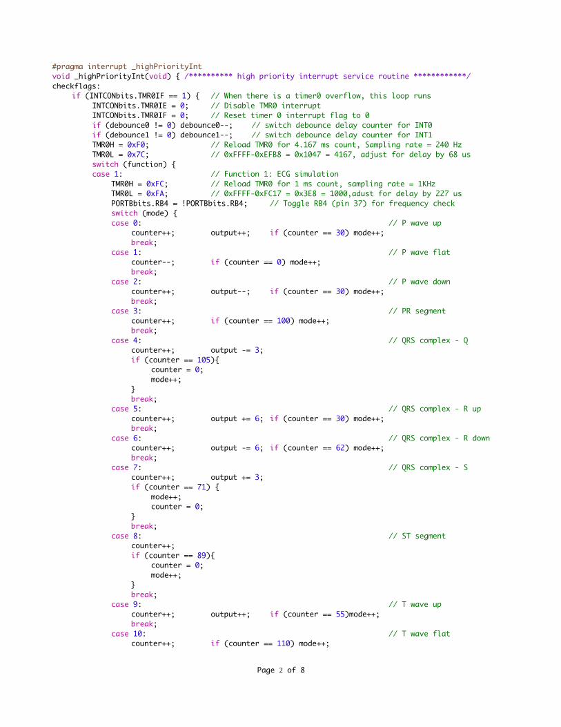
TMR0H = 0xFC; // Reload TMR0 for 1 ms count, sampling rate = 1KHzTMR0L = 0xFA; // 0xFFFF-0xFC17 = 0x3E8 = 1000,adust for delay by 227 usPORTBbits.RB4 = !PORTBbits.RB4; // Toggle RB4 (pin 37) for frequency checkswitch (mode) {case 0: // P wave up
counter++; output++; if (counter == 30) mode++;break;
case 1: // P wave flatcounter--; if (counter == 0) mode++;break;
case 2: // P wave downcounter++; output--; if (counter == 30) mode++;break;
case 3: // PR segmentcounter++; if (counter == 100) mode++;break;
case 4: // QRS complex - Qcounter++; output -= 3;if (counter == 105){
counter = 0;mode++;
}break;
case 5: // QRS complex - R upcounter++; output += 6; if (counter == 30) mode++;break;
case 6: // QRS complex - R downcounter++; output -= 6; if (counter == 62) mode++;break;
case 7: // QRS complex - Scounter++; output += 3;if (counter == 71) {
mode++;counter = 0;
}break;
case 8: // ST segmentcounter++;if (counter == 89){
counter = 0;mode++;
}break;
case 9: // T wave upcounter++; output++; if (counter == 55)mode++;break;
case 10: // T wave flatcounter++; if (counter == 110) mode++;
Page 2 of 8
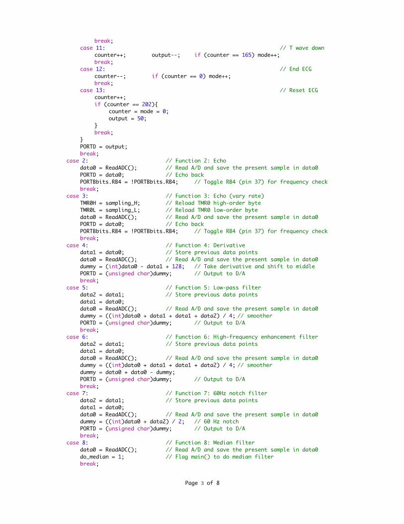
break;case 11: // T wave down
counter++; output--; if (counter == 165) mode++;break;
case 12: // End ECGcounter--; if (counter == 0) mode++;break;
case 13: // Reset ECGcounter++;if (counter == 202){
counter = mode = 0;output = 50;
}break;
}PORTD = output;break;
case 2: // Function 2: Echodata0 = ReadADC(); // Read A/D and save the present sample in data0PORTD = data0; // Echo back PORTBbits.RB4 = !PORTBbits.RB4; // Toggle RB4 (pin 37) for frequency checkbreak;
case 3: // Function 3: Echo (vary rate)TMR0H = sampling_H; // Reload TMR0 high-order byteTMR0L = sampling_L; // Reload TMR0 low-order bytedata0 = ReadADC(); // Read A/D and save the present sample in data0PORTD = data0; // Echo back PORTBbits.RB4 = !PORTBbits.RB4; // Toggle RB4 (pin 37) for frequency checkbreak;
case 4: // Function 4: Derivativedata1 = data0; // Store previous data pointsdata0 = ReadADC(); // Read A/D and save the present sample in data0dummy = (int)data0 - data1 + 128; // Take derivative and shift to middlePORTD = (unsigned char)dummy; // Output to D/Abreak;
case 5: // Function 5: Low-pass filterdata2 = data1; // Store previous data pointsdata1 = data0;data0 = ReadADC(); // Read A/D and save the present sample in data0dummy = ((int)data0 + data1 + data1 + data2) / 4; // smootherPORTD = (unsigned char)dummy; // Output to D/Abreak;
case 6: // Function 6: High-frequency enhancement filterdata2 = data1; // Store previous data pointsdata1 = data0;data0 = ReadADC(); // Read A/D and save the present sample in data0dummy = ((int)data0 + data1 + data1 + data2) / 4; // smootherdummy = data0 + data0 - dummy;PORTD = (unsigned char)dummy; // Output to D/Abreak;
case 7: // Function 7: 60Hz notch filterdata2 = data1; // Store previous data pointsdata1 = data0;data0 = ReadADC(); // Read A/D and save the present sample in data0dummy = ((int)data0 + data2) / 2; // 60 Hz notchPORTD = (unsigned char)dummy; // Output to D/Abreak;
case 8: // Function 8: Median filterdata0 = ReadADC(); // Read A/D and save the present sample in data0do_median = 1; // Flag main() to do median filterbreak;
Page 3 of 8

case 9: // Function 9: Heart rate meterTMR0H = 0xED; // Reload TMR0 for 5 ms count, sampling rate = 200 HzTMR0L = 0x44; // 0xFFFF-0xED44 = 0x12BB = 4795, (205 us delay)data1 = data0; // Move old ECG sample to data1data0 = ReadADC(); // Store new ECG sample from ADC to data0PORTBbits.RB2 = !PORTBbits.RB2; // Toggle RB2 for sampling rate checkdo_MOBD = 1; // Flag main() to do MOBD for QRS detectionbreak;
}INTCONbits.TMR0IE = 1; // Enable TMR0 interrupt
}if (INTCONbits.INT0IF == 1) { // INT0 (pin 33) negative edge
INTCONbits.INT0IE = 0; // Disable interruptINTCONbits.INT0IF = 0; // Reset interrupt flagif (debounce0 == 0) {
if (function <= 0) function = 9; // Set function range 0-9else function--;if (function == 9) SetupADC(1); // ECG comes from AN1 channelelse SetupADC(0); // Others come from AN0 channelupdate = 1; // Signal main() to update LCD dispalydebounce0 = 10; // Set switch debounce delay counter decremented by TMR0
}INTCONbits.INT0IE = 1; // Enable interruptgoto checkflags; // Check again in case there is a timer interrupt
}if (INTCON3bits.INT1IF == 1) { // INT1 (pin 34) negative edge
INTCON3bits.INT1IE = 0; // Disable interruptINTCON3bits.INT1IF = 0; // Reset interrupt flagif (debounce1 == 0) {
if (function >= 9) function = 0; // Set function range 0-9else function++;if (function == 9) SetupADC(1); // ECG comes from AN1 channelelse SetupADC(0); // Others come from AN0 channelupdate = 1; // Signal main() to update LCD dispalydebounce1 = 10; // Set switch debounce delay counter decremented by TMR0
}INTCON3bits.INT1IE = 1; // Enable interruptgoto checkflags; // Check again in case there is a timer interrupt
}}
void Transmit(unsigned char value) { /********** Send an ASCII Character to USART ***********/while(!PIR1bits.TXIF) continue; // Wait until USART is readyTXREG = value; // Send the datawhile (!PIR1bits.TXIF) continue; // Wait until USART is readyDelay_ms (5); // Wait for 5 ms
}
void ClearScreen(){ /************************** Clear LCD Screen ***************************/Transmit(254); // See datasheets for Serial LCD and HD44780Transmit(0x01); // Available on our course webpage
}
void Backlight(unsigned char state){ /************* Turn LCD Backlight on/off ***************/Transmit(124);if (state) Transmit(0x9D); // If state == 1, backlight onelse Transmit(0x81); // otherwise, backlight off
}
void SetPosition(unsigned char position){ /********** Set LCD Cursor Position *************/Transmit(254);
Page 4 of 8

Transmit(128 + position);}
void PrintLine(rom unsigned char *string, unsigned char numChars){ /**** Print characters ****/unsigned char count;for (count=0; count<numChars; count++) Transmit(string[count]);
}
void PrintInt(int value, unsigned char position){ /******** Print number at position *********/int units, tens, hundreds, thousands;SetPosition(position); // Set at the present positionif (value > 9999) {
PrintLine((rom unsigned char*)"Over", 4);return;
}if (value < -9999) {
PrintLine((rom unsigned char*)"Under", 5);return;
}if (value < 0) {
value = -value;Transmit(45);
}else Transmit(43);thousands = value / 1000; // Get the thousands digit, convert to ASCII and sendif (thousands != 0) Transmit(thousands + 48);value = value - thousands * 1000;hundreds = value / 100; // Get the hundreds digit, convert to ASCII and sendTransmit(hundreds + 48);value = value - hundreds * 100;tens = value / 10; // Get the tens digit, convert to ASCII and sendTransmit(tens + 48);units = value - tens * 10;Transmit(units + 48); // Convert to ASCII and send
}
void PrintNum(unsigned char value1, unsigned char position1){ /** Print number at position ***/int units, tens, hundreds, thousands;SetPosition(position1); // Set at the present positionhundreds = value1 / 100; // Get the hundreds digit, convert to ASCII and sendif (hundreds != 0) Transmit(hundreds + 48);else Transmit(20);value1 = value1 - hundreds * 100;tens = value1 / 10; // Get the tens digit, convert to ASCII and sendTransmit(tens + 48);units = value1 - tens * 10;Transmit(units + 48); // Convert to ASCII and send
}
void SetupSerial(){ /*********** Set up the USART Asynchronous Transmit (pin 25) ************/TRISC = 0x80; // Transmit and receive, 0xC0 if transmit onlySPBRG = 25; // 9600 BAUD at 4MHz: 4,000,000/(16x9600) - 1 = 25.04TXSTAbits.TXEN = 1; // Transmit enableTXSTAbits.SYNC = 0; // Asynchronous modeRCSTAbits.CREN = 1; // Continuous receive (receiver enabled)RCSTAbits.SPEN = 1; // Serial Port EnableTXSTAbits.BRGH = 1; // High speed baud rate
}
void SetupADC(unsigned char channel){ /******** Configure A/D and Set the Channel **********/TRISA = 0b11111111; // Set all of Port A as input
Page 5 of 8
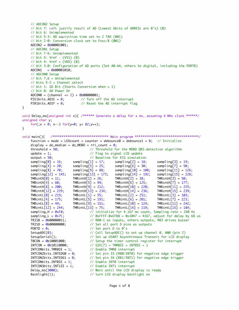
// ADCON2 Setup// bit 7: Left justify result of AD (Lowest 6bits of ADRESL are 0's) (0)// bit 6: Unimplemented// bit 5-3: AD aquisition time set to 2 TAD (001)// bit 2-0: Conversion clock set to Fosc/8 (001)ADCON2 = 0b00001001;// ADCON1 Setup// bit 7-6: Unimplemented// bit 5: Vref - (VSS) (0)// bit 4: Vref + (VDD) (0)// bit 3-0: Configuration of AD ports (Set A0-A4, others to digital, including the PORTB)ADCON1 = 0b00001010;// ADCON0 Setup// bit 7,6 = Unimplemented// bits 5-2 = Channel select// bit 1: GO Bit (Starts Conversion when = 1)// bit 0: AD Power OnADCON0 = (channel << 2) + 0b00000001;PIE1bits.ADIE = 0; // Turn off the AD interruptPIR1bits.ADIF = 0; // Reset the AD interrupt flag
}
void Delay_ms(unsigned int x){ /****** Generate a delay for x ms, assuming 4 MHz clock ******/unsigned char y;
for(;x > 0; x--) for(y=0; y< 82;y++);}
void main(){ /****************************** Main program **********************************/function = mode = LEDcount = counter = debounce0 = debounce1 = 0; // Initializedisplay = do_median = do_MOBD = rri_count = 0;threshold = 50; // Threshold for the MOBD QRS-detection algorithmupdate = 1; // Flag to signal LCD updateoutput = 50; // Baseline for ECG simulationsampling[0] = 16; sampling[1] = 17; sampling[2] = 18; sampling[3] = 19;sampling[4] = 20; sampling[5] = 25; sampling[6] = 30; sampling[7] = 50;sampling[8] = 70; sampling[9] = 88; sampling[10] = 108; sampling[11] = 126;sampling[12] = 145; sampling[13] = 173; sampling[14] = 192; sampling[15] = 228;TMRcntH[0] = 11; TMRcntH[1] = 26; TMRcntH[2] = 38; TMRcntH[3] = 50;TMRcntH[4] = 60; TMRcntH[5] = 99; TMRcntH[6] = 125; TMRcntH[7] = 177;TMRcntH[8] = 200; TMRcntH[9] = 212; TMRcntH[10] = 220; TMRcntH[11] = 225;TMRcntH[12] = 229; TMRcntH[13] = 234; TMRcntH[14] = 236; TMRcntH[15] = 239;TMRcntL[0] = 219; TMRcntL[1] = 55; TMRcntL[2] = 251; TMRcntL[3] = 103;TMRcntL[4] = 175; TMRcntL[5] = 191; TMRcntL[6] = 201; TMRcntL[7] = 223;TMRcntL[8] = 49; TMRcntL[9] = 151; TMRcntL[10] = 124; TMRcntL[11] = 242;TMRcntL[12] = 244; TMRcntL[13] = 75; TMRcntL[14] = 119; TMRcntL[15] = 184;sampling_H = 0xF0; // initialize for 4.167 ms count, Sampling rate = 240 Hzsampling_L = 0x7C; // 0xFFFF-0xEFB8 = 0x1047 = 4167, adjust for delay by 68 usTRISB = 0b00000011; // RB0-1 as inputs, others outputs, RB3 drives buzzerTRISD = 0b00000000; // Set all port D pins as outputsPORTD = 0; // Set port D to 0'sSetupADC(0); // Call SetupADC() to set up channel 0, AN0 (pin 2)SetupSerial(); // Set up USART Asynchronous Transmit for LCD displayT0CON = 0b10001000; // Setup the timer control register for interruptINTCON = 0b10110000; // GIE(7) = TMR0IE = INT0IE = 1INTCONbits.TMR0IE = 1; // Enable TMR0 interruptINTCON2bits.INTEDG0 = 0; // Set pin 33 (RB0/INT0) for negative edge triggerINTCON2bits.INTEDG1 = 0; // Set pin 34 (RB1/INT1) for negative edge triggerINTCONbits.INT0IE = 1; // Enable INT0 interruptINTCON3bits.INT1IE = 1; // Enable INT1 interruptDelay_ms(3000); // Wait until the LCD display is readyBacklight(1); // turn LCD display backlight on
Page 6 of 8

ClearScreen(); // Clear screen and set cursor to first positionPrintLine((rom unsigned char*)" BME 361 Demo", 14);SetPosition(64); // Go to beginning of Line 2;PrintLine((rom unsigned char*)" Biomeasurement",15); // Put your trademark here Delay_ms(3000);ClearScreen(); // Clear screen and set cursor to first positionPrintLine((rom unsigned char*)"Function", 8);while (1) {
if (update) { // The update flag is set by INT0 or INT1update = 0; // Reset update flagPrintNum(function, 8); // Update the function number on LCD displayif (function != 0) LEDcount = PORTB = 0; // Reset LED'sSetPosition(64); // Go to beginning of Line 2;switch (function) {
case 0: PrintLine((rom unsigned char*)"Binary counter ",16); break; case 1: PrintLine((rom unsigned char*)"ECG simulation ",16); break; case 2: PrintLine((rom unsigned char*)"Echo (A/D - D/A)",16); break; case 3: PrintLine((rom unsigned char*)"Echo @ fs Hz",16); break; case 4: PrintLine((rom unsigned char*)"Derivative ",16); break; case 5: PrintLine((rom unsigned char*)"Low-pass filter ",16); break; case 6: PrintLine((rom unsigned char*)"Hi-freq enhance ",16); break; case 7: PrintLine((rom unsigned char*)"60Hz notch filtr",16); break; case 8: PrintLine((rom unsigned char*)"Median filter ",16); break; case 9: PrintLine((rom unsigned char*)"HR = bpm ",16); break;
}}switch (function) {case 0: // Function 0: Binary counter
LEDcount++; // UpcounterPORTB = LEDcount & 0b11110000; // Mask out the lower 4 bitsPORTD = LEDcount; // Output ramp to verify linearity of the D/ADelay_ms(10); // Delay to slow down the countingbreak;
case 3: // Function 3: Echo (vary rate)INTCONbits.TMR0IE = 0; // Disable TMR0 interruptSetupADC(2); // Switch to A/D channel AN2counter = ReadADC(); // Read potentiometer setting from AN2SetupADC(0); // Switch to A/D channel AN0counter = counter >> 4; // Scale it to 0-15temp = sampling[counter]; // Display sampling ratePrintNum(temp,74);sampling_L = TMRcntL[counter]; // Load TMR0 low-order bytesampling_H = TMRcntH[counter]; // Load TMR0 high-order byteINTCONbits.TMR0IE = 1; // Enable TMR0 interruptDelay_ms(1000); // Delay to slow down the countingbreak;
case 8: // Function 8: Median filter (9-point)if (do_median) {
do_median = 0; // Reset do_median flagINTCONbits.TMR0IE = 0; // Disable TMR0 interruptfor (i=8; i>0; i--) array[i] = array[i-1]; // Store the previous 8 pointsarray[0] = data0; // Get new data point from A/Dfor (i=0; i<9; i++) rank[i] = array[i]; // Make a copy of data arrayfor (i=0; i<5; i++) { // Perform a bubble sort
for (j=i+1; j<9; j++) {if (rank[i] < rank[j]) {
temp = rank[i]; // Swaprank[i] = rank[j];rank[j] = temp;
}}
Page 7 of 8

}PORTD = rank[4]; // Median is at rank[4] of rank[0-8]INTCONbits.TMR0IE = 1; // Enable TMR0 interrupt
}break;
case 9: // Function 9: Multiplication of Backward Differences (MOBD)if (do_MOBD){ // MOBD = Multiplication of Backwards Differences
INTCONbits.TMR0IE = 0; // Disable TMR0 interruptdo_MOBD = 0; // Reset new_data flagd2 = d1; // Move oldest difference to d2d1 = d0; // Move older difference to d1d0 = (int)data0 - data1; // Store new difference in d0, (int) casting importantrri_count++; // Increment RR-intervalmobd = 0; // mobd = 0, unless sign consistency is met:if (d0 > 0 && d1 > 0 && d2 > 0){ // (1) If 3 consecutive positive differences
mobd = d0 * d1; // Multiply first two differencesmobd = mobd >> 3; // Scale down (divide by 8)mobd = mobd * d2; // Multiply the oldest difference
}if (d0 < 0 && d1 < 0 && d2 < 0){ // (2) If 3 consecutive negative differences
d0 = -d0; // Take absolute value of differencesd1 = -d1;d2 = -d2;mobd = d0 * d1; // Multiply first two differencesmobd = mobd >> 3; // Scale down (divide by 8)mobd = mobd * d2; // Multiply the oldest difference
}if (refractory){ // Avoid detecting extraneous peaks after QRS
refractory++;if (refractory == 40){ // Delay for 200 ms
refractory = 0; // Reset refractory flag to 0PORTBbits.RB3 = 0;// Turn buzzer/LED off (Pin 36)
}}else if (mobd > threshold){ // If a peak is detected,
refractory = 1; // Set refractory flagPORTBbits.RB3 = 1; // Turn buzzer/LED on (Pin 36)display = 1; // Set display flag
}PORTD =(unsigned char)mobd; // Output mobd value to Port DINTCONbits.TMR0IE = 1; // Enable TMR0 interrupt
}if (display){ // Display Heart Rate in 3 digits
hr = 12000/rri_count; // 60/0.005 = 12000rri_count = 0; // Reset RRI counterPrintNum(hr, 71); // Isolates each digit and displaysdisplay = 0; // Reset display flag
}break;
}}
}
Page 8 of 8