bmd plug gauges - diatest hermann költgen gmbh · instruments. these easy-to-use gauges are...
TRANSCRIPT

BMD PLUG GAUGES Technical Guide Version 4

Content
Page
3 DIATEST - Expertise for precision and safety
4 Technical description
9 Basic plug gauge types
10 Basic type - Standard
11 Basic type for through bores
12 Basic type for blind bores
13 Basic types with compressed air supply
14 Plug gauges for automatic gauging
15 Special-purpose plug gauges
21 PA for measuring parallel wall gaps
22 Multiplane plug gauges
24 Indicator holders
Page
27 Indicator holders with adjustable spring pressure
29 Electrical probe holders
30 Special gauge holders
33 Holders for Analodig indicators
34 Adapters
36 Right-angle attachments
37 Depth extensions
40 Depth stops
42 Small measurement fixtures
46 Floating holders
50 Spare parts
51 General and technical abbreviations
2

Safety through qualityCompetence for precision and safety
High-volume engineering does not work without precision.
To achieve highest possible safety in production, preci-
sion is necessary starting from design to final product.
Here the trademark DIATEST stands for quality.
Gauges with repeatabilities to 0.001 mm/0.00005“
and even better guarantee exact results.
DIATEST bore gauges are manufactured according to
DIN EN ISO 9001. Using state-of-the-art manufacturing
engineering the highest quality standards are achieved.
Our products withstand technological demands,
no matter whether it is a question of standard products
or special solutions made to customer’s specifications.
This is the company’s philosophy, carried out by an expe-
rienced staff: Highest quality at a fair cost effectiveness,
combined with expert advice and absolute faithfulness
to deadlines in dealing with all DIATEST customers.
For us this is a service taken for granted which our
DIATEST partners worldwide appreciate.
This is what partnership means to us.
3

Technical description
Plug gauges (BMD) are self-in-dicating, self-centering, high precision measurement instruments. These easy-to-usegauges are suitable for both staticand dynamic measurements.They can be used for manualdetection of dimensional deviations and shape defectsin bores in serial measurement at the machine but may alsobe installed in measuring equip-ment and automated systems.
A broad range of applications,ease of handling, superior preci-sion and rugged constructionare combined in a highly cost-effective system. A wide selection of basic types in the standard programme, supplemented by useful accesso-ries, ensures that nearly all bores encountered in actual practice can be measured precisely.
The range of display instrumentsincludes mechanical indicators,digital displays and sensorsconnected to analytical equip-ment. Peripheral equipmentprovides for static data analysis,dimension-based tool control andmany other useful options.
Special models
The BMD Technical Guide is intended to assist you in selecting the most suitable measurement equipment. For special measure-ment problems we need a detailed description of the measurement task as well as adrawing or sample in order toprepare an offer. An optimum offerdepends on precise, completeinformation.Please note: Deviationsregarding technical aspects ofspecially designed BMD gaugesas opposed to standard gaugesare possible!
Special markings (SO-B) Special markings data matrix code (SO-B-DMC)(extra charge)
We can provide special markings,such as customer-specific IDnumbers, tolerances, etc. Pleasekeep in mind that the possibilitiesfor adding special markings tosmall plug gauges are limited.The surcharge for SO-B is calcu-lated for each commenced 10characters (see price list).
Design and materialcharacteristics:
Probe: spring steel, approx. 61HRCNeedles: carbide, approx.1650 HVGuide cylinder: gauge steel,approx. 60 HRCHard chrome coating on guidecylinders, approx. 1000 HV(standard design)Special cylinder designs: OCR = steel cylinders, hardened and black finishedPlease note: OCR plug gaugesare not suitable for roughmeasurement conditions.ZHML = cylinder with carbidebars, page 14ZKUL = cylinder with plastic bars,page 17
Technical data
All dimensions are quoted in mmunless otherwise specified.We reserve the right to maketechnical modifications in orderto improve performance. Minordeviations which do not impactsignificantly on measurementequipment performance mayoccur.Information regarding technologi-cal advances and the mostrecent version of our documenta-tion is also available on theInternet at www.diatest.com
Zero setting
Zero setting should be performedwith the aid of a setting ring thatcorresponds precisely to theminimum bore size. This ensuresthat the risk of radial and axialerrors is largely eliminated duringthe calibration process.
The most suitable setting ringsare those which comply with thespecifications of DIN 2250-C.Setting rings with larger dimen-sions or for minimum, mediumand maximum dimensions aregenerally not required.
Function
The guide cylinder (4) centers theprobe gauging contacts (6) fixed to the split ball probe (5) axially and radially in the bore.The lapped cone of the needle(3) translates the distance travelledby the gauge contacts 1:1 tothe indicator (1) clamped in theholder (2).
44
TA-KW
SO-ZL

Safety through qualityTechnical description
Production times
Production times are quoted exfactory, as shown in the table below.
Service life
Service life depends upon such conditions as work piece surface quality (roughness, coating), material, length of measured bore, dirt accumulation, gauging pressure etc. Up to a few million measurements are possible under optimum conditions.
Repair Service
DIATEST offers a fast and cost-effective repair service for stand-ard BMD.Service 1: Exchange of gaugingunit and functional testing.Approx. 10 days, ex works.Service 2: Exchange of gaugingunit, fully re-chromed cylinder andfunctional testing. Approx. 15 days, ex works.A cost estimate for special BMD plugs will be provided (on request).
Maintenance
No special maintenance isrequired. If cleaning is needed,remove the needle and clean theplug gauge and the needle care-fully with compressed air and a cleaning solution.
Please note: The needle tapershould be greased prior toinstallation (e.g. Vaseline). When installing needles for Series 6 and 10, please ensure that springs are remounted (no springs in Series 4).
ability due to tipping and lateral shifting.
Nominal dimensions andstandard measurementranges
Plug gauge order dimension(nominal dimension) = minimumbore dimensionExample:Ø 35 D7 = Ø 35 +0.08/+0.105BMD nom. dimension = 35.08Ø 35 H7 = Ø 35 +0/+0.025BMD nom. dimension = 35.0
Measuring range extension (MB-SO)(extra charge)
The standard measuring rangecan be extended for applicationsrequiring measurement of largerbore tolerances. Please note:Some plug gauges with MB-SOhave smaller contact point radii.This poses the danger of axialand radial errors. Please enquirebefore using diamond measure-ment contacts.A measuring range extensionof e.g. MB-SO+0.4 indicates thatthe entire measurement range ofthe plug gauge is 0.4 mm, basedon the nominal plug gaugedimension.Measurements taken in horizon-tal direction may lead to smaller measuring ranges.
Gauging accuracy
Maximum allowed deviationswith new plug gauges:
Repeatability2-point designfw ≤ 0.001 mm3-point designfw ≤ 0.002 mm
Measuring range transmission error (Linearity)2-point modelsfe = 1% of gauging distancemin. 0.0013-point modelsfe = 3% of gauging distancemin. 0.002
FB designfe = 2% of gauging distancemin. 0.001
Measurement range extension (MB-SO) and special designs may lead to a reduced measuring accuracy.
Axial and radial centeringerrors
The plug gauge guide cylinderpositions the gauging contacts inthe bore and ensures highrepetition accuracy. Short guidepaths and/or excessive clearancebetween the bore and the guidecylinder result in lower repeat-
55
Standard production times
Plug gauge type working days
S, D, PK, OR, 2R, S-FB up to nom. dim. 100 mm 10S, D, PK, OR, 2R, S-FB above nom. dim. 100 mm 15FB, 3P, L, PK-2Z, MZ, AT0 15SO-TA, UM, PA, SO-GL, SO-W10, T-BMD 25SO-KO, SO-ZL, SO-2Z, ZHML, SO-PA etc. 30
Saturdays, Sundays, public holidays and company holidays are not counted as production days and will extend delivery times accordingly.
Measuring range, based on nominal BMD dimension
BMD series Application range Measuring range
4 Ø 2.98 - 9.0 + 0.1 mm6 Ø 7.0 - 20.0 + 0.15 mm10 Ø 15.0 - 270.0 + 0.2 mmFB6 Ø 7.0 - 16.0 + 0.15 mmFB10 Ø 15.0 - 150.0 + 0.15 mm3P (Series 6) Ø 8.0 - 20.0 + 0.15 mm3P (Series 10) Ø 15.0 – 100.0 + 0.2 mmT-BMD Ø 2.25 (PA 1.0) - 2.98 + 0.15 mm
Express production times (extra charge)
Plug gauge type working days
S, D, PK, OR, 2R, S-FB up to nom. dim. 100 mm 5-8S, D, PK, OR, 2R, S-FB above nom. dim. 100 mm 8-10FB, 3P, L, PK-2Z, MZ, AT0 8-10SO-TA, UM, PA, SO-GL, SO-W10, T-BMD 15SO-KO, SO-ZL, SO-2Z, ZHML, SO-PA etc. 15
Delivery times for all other plug gauges, including multiplane gauges, etc, will be quoted on request.
Measuring range extension (MB-SO)
BMD series max. meas. range (order suffix)
Series 4 Ø 2.98 - 4.0 max. MB-SO + 0.15Series 4 Ø > 4.0 max. MB-SO + 0.2Series 6 max. MB-SO + 0.4Series 10 to Ø 120 mm max. MB-SO + 0.8Series 10 Ø > 120 to 180 mm max. MB-SO + 0.6Series 10 Ø > 180 to 220 mm max. MB-SO + 0.4Series 10 Ø > 220 to 270 mm max. MB-SO + 0.3Series FB10 + FB6 max. MB-SO + 0.3BMD-3P (Serie 6) max. MB-SO + 0.3BMD-Series 10 3P max. MB-SO + 0.4
For option MB-SO we recommend option PG in addition (page 8).

Technical description
Measuring rangelimitation (MB-B)
For plugs series 6, 10 and FB the standard measuring range can be reduced, if requested. Order suffix: MB-B and max. desired measuring range.Sample order for max. measuringrange of +0.1 mm insteadof 0.2 mm:BMD-S10-CR-35.0-MB-B+0.1Washers can also be used toreduce the measurement range.DIATEST offers a line of washersfor this purpose:BMD Series 6 US-6BMD Series 10 US-10
Indicators, measuringpressure
Plug gauges can be used withnearly all mechanical and elec-tronic indicator units with Ø 8hand 3/8“ stem. Measuring pres-sure has a significant influence on the service life and accuracy of BMD.Recommended measuringpressures for standardmeasurement ranges:BMD Series 4 appro. 0.3 – 0.4 NBMD Series 6 appro. 0.6 – 1.0 NBMD Series 10 appro. 0.8 – 1.6 NPlease note:It may be necessary to increasemeasuring pressure when usingoptions MB-SO and PG.
Measuring pressurereduction
Only low gauging pressure isneeded when using Series 4 BMD,to measure thin-walled objectsor to reduce wear on measuring contacts. It is often impossible to obtain a suitable reading. Special indicator holders or adapters can be used to reduce the measuring pressure of the indicator. In addition, option PG provides for the possibility of lifting the gauging contacts from the bore surface.
Type PG Page 8Holder MH6-73-R Page 24Holder MH10-150-PG Page 32Holder MH10-150-R Page 25Holder MH10-150-F Page 30Adapter A4-10-F Page 34Adapter A6-6-F Page 35MH4-67-F Page 28MH6-65-F Page 28
Contact points
Large contact point radii (see table MHM) are important toensure long service life and arerequired when gauging boreswith rough surfaces. Our BMDgauging contacts meet theserequirements. The selection of gauging contact material depends on the compo-sition of the workpiece and the conditions affecting wear. BMD gauging contacts areavailable in several differentmaterials.. If you are not sure
which material is best suited for your workpiece please get in touch with us.
Carbide contact points (MHM) Plug gauges are fitted with car-bide contact points (standard, no extra charge).Carbide: approx. 1850 HVCarbide should not be used forworkpieces composed of non-ferrous metal, aluminium or their alloys.
Hard chrome contact points (MCR) Hard chrome contacts are suitable for use with non-ferrous metals, aluminium and their alloys. These contact points are made of carbide steel coated with a hardchrome layer. The hard chrome layer is approx. 0.03 mm thick. Option MCR is not suited for ap-plications involving heavy wearconditions or very soft workpiecematerials. In these cases, it isadvisable to opt for diamondgauging contacts (MDI).Contact point radii(see Table MHM)Hardness: approx. 1000 HVOrder suffix: MCRAvailable for nominal diametersof 3,95 and above.Example:BMD-S10-CR-35.0-MCR
Ceramic contact points (MKE)(extra charge)Like option MCR, ceramiccontact points are suited foruse with non-ferrous metals andaluminium. When working with very soft aluminium materials, the ceramic material may discolour. This has no impact on performance or measuring accuracy, however.Hardness: Knoop 100g18000 Grain size: 0.5 μmContact point radii(see table MHM)Not available for series 4 and BMD-FBOrder suffix: MKEExample:BMD-S10-CR-35.0-MKE
6
Contact points carbide (MHM)
BMD series Diameter range gauging radius
Series 4 2.98 - 9.0 R = 0.5Series 6 7.0 - 20.0 R = 2.0Series 10 15.0 - 25.0 R = 2.5
> 25.0 - 31.0 R = 4.5> 31.0 - 35.0 R = 6.5> 35.0 - 41.0 R = 8.5> 41.0 - 47.0 R = 10.5> 47.0 - 56.0 R = 13.0> 56.0 - 66.0 R = 16.0> 66.0 - 120.0 R = 20.0
> 120.0 - 150.0 R = 25.0> 150.0 - 270.0 R = 30.0
Option MB-SO+0.4 to 0.5 R = 4.5Option MB-SO+0.5 and above R = 2.5BMD-FB6 7.0 - 16.0 R = 2.0BMD-FB10 15.0 - 18.0 R = 1.0
> 18.0 - 150.0 R = 1.5BMD-ME - R = 4.5BMD-PK (Series 10) - R = 2.5BMD-PK (Series 6) 7.9 - 20.0 R = 2.0BMD-3P (Series 10) - R = 2.5BMD-3P (Series 6) 8.0 - 20.0 R = 2.0

Safety through qualityTechnical description
Ruby contact points (MRU)(extra charge)For non-ferrous metals, aluminiumand their alloys.It may be necessary to opt fordiamond contacts when workingwith very soft aluminium materials,etc.contact point radii,see table MHMHardness ruby: approx. 2000 HVOrder suffix: MRUExample:BMD-S10-35.0-MRUNot available for Series 4 and FB
Diamond contact points (MDI)(extra charge)Suitable for use with extremelysoft aluminium materials, underheavy wear conditions (e.g.automatic measurement) and withhighly polished surfaces, etc.These contact points are madeof natural diamond (available for nominal diameters of 3,95 and above).Please note: The contact pointmay be damaged while workingwith sharp-edged workpieces.Please inquire before using theMB-SO extended range option. MDI contacts not available for series FB6 and FB10.
Protective cover AD(extra charge)
Plastic contact points (MKK)(extra charge)These gauging contacts shouldbe used only under certainspecific conditions, e.g. for highlypolished surfaces.The contact points consist ofpolyamide balls (Ø 4.0 mm).These elements can be replacedby the customer.Available for nominal diametersof 25.0 mm and above. Type Sor D only.Maximum measurement range:MB-SO+0.3Order suffix: MKKExample:BMD-S10-CR-35.0-MKK
Service life
Service life depends upon suchconditions as workpiece surfacequality (roughness, coating),material, length of the measuredbore, measuring pressure, etc. Upto 1,000,000 measurements arepossible under optimum condi-tions.
Protective covers should be usedwith caution. Covers protectmechanical parts and reduce therisk of dirt accumulation.However, they make it difficult toremove chips, coolants and otherdeposits.
The following options may beselected for applications involvingheavy wear conditions:– Air cleaning (L) Page 13– PG Page 8– MDI Page 7– PK-ZHML Page 14– measuring pressure reduction Page 6
Standard protective covers aremade of aluminum. Covers madeof steel, hardened steel and othermaterials are available on request.Depending on nominal diameterand design, protective covers areeither glued or screwed in place.
Covers for types S and S-FBCovers for type S are availablefor nominal diameters of 4.0 andabove. Up to a nominal diameterof 28.0, the dimension L1increases by 0.5 mm. For nominaldiameters of 28.0 and above,dimension L1 increases by2.0 mm.Order suffix: AD-SExample:BMD-S10-CR-35.0-AD-S
Covers for type DDimension L1 increases by 1 mm.Order suffix: AD-DExample:BMD-D10-CR-35,0-AD-D
Covers for type FBBMD-FB6: Dimension L1increases by 1 mm. For seriesBMD-FB10, nominal diameters15-28 mm, dimension L1increases by 0.5 mm and fornominal diameters of 28 mm by2 mm.Order suffix: AD-FBExample:BMD-FB10-CR-35.0-AD-FB
7
Contact points diamond (MDI)
BMD series Diameter range Gauging radius
Series 4 3.95 - 9.0 R = 0.5Series 6 7.0 - 16.0 R = 2.0Series 10 15.0 - 270.0 R = 2.5Order suffix MDIExample BMD-S10-CR-35.0-MDI
SO-KW PK-ZHML
SO-2Z
BMD-ME BMD-OD

AT0
AT0
Technical description
Reduced cylinder diameter tolerance (MZ)(extra charge)
The manufacturing tolerances forguide cylinders indicated for BMDtypes S and D (Page 10, 11) arereduced to 0.01 mm (±0.005). Thepurpose is to reduce axial andradial errors to a minimum. Thisoption should be used only forvery small bore tolerances (toapprox. 0.01 mm).Cylinder production tolerance(min. bore diameter –0.01)±0.005 mmOrder suffix: MZThe MZ dimension is approx. 0.01mm lower than the minimum borediameter (= nominal BMD diameter).Example:Min. bore diameter = 35.0MZ diameter = 34.99BMD-S10-35.0-MZ-34.99The guide cylinder is manufac-tured with a diameter ofØ 34.99 ±0.005 mmRange of applicationØ 4,0 – 100,0 mm.Other diameter dimensions onrequest.
Inspection plug gauge (BM) (on request, extra charge)
The inspection plug gauge is afull-form GO gauge used tomeasure minimum bore diameter.If the inspection gauge can beinserted into the bore, the exactactual diameter as well as anyshape defects are shown on theindicator.Series 6 Ø 8.0 – 20.0Series 10 Ø >20 – 100.0Quality ISO6 or to customerspecification
BMD without inherentgauging pressure (PG)
Without an indicator, BMD plugs have an inherent gauging pressure of approx. 0.2 – 1.7 N.In option PG – without inherentgauging pressure – the built-inprobe is not pre-extended.The contact points are retracted beneath the surface of the guide cylinder. This option should be selected e.g. for use with sensitive or rough workpiece surfaces.Please note:Indicator gauging pressures mustbe higher, as the probe exerts no pressure of its own.Option PG should be used inconjunction with the followingaccessories:Holders:MH-6-73-R Page 24MH-10-150-R Page 25MH-10-150-PG Page 32Order suffix: PGExample:BMD-S10-35.0-PG
Toleranced connectinglength (AT0) (extra charge)
Depending on how the gaugingunit is installed, the needle mayprotrude at different lengths(differences of up to 1.0 mm).Especially when electronic probesare used, the gauge has to bereadjusted in the holder when theplug gauge is changed (electricalzero point). In order to avoid thisproblem, the dimension from thestop collar to the needle is ad-justed with a tolerance of ±0.02 in option AT0. The adjustment ismade in the setting ring at thenominal dimension. This optionrequires that the setting ring beordered with the component.
Important dimension-based codes for special types
A Length of pilot taper 15°/30° (page 14)AD Cover AD-S, AD-DAT0 toleranced connecting lengthL1 Length from contact midpoint to BMD faceL2 Length from contact midpoint to cylinder end L3 Length from contact midpoint to depth stopL4 Length from contact midpoint to end of threadingMB-B Measurement range limitationMB-SO Extended measurement rangeMZ Limited Z dimension MR-SO Special gauging contact radiiØZ Actual diameter of BMD cylinder
Please note:If the plug gauge is used withsuch accessories as depthextensions, right angle attach-ments, etc., option AT0 must cover the entire unit (accessories are not interchangeable).
BMD series AT0Series 4 12.55 ±0.02Series 6 12.18 ±0.02Series 10 21.96 ±0.02Order suffix: AT0Example:BMD-S10-35.0-AT0BMD-S10-35.0+TV-15-64-AT0
Note:Dimension AT0 changes as aresult of mechanical wear.
8
SO-KO PA6 FB-10

Safety through qualityBMD plug gauges – Basic types
In diameters of up to 44.0 mm,the guide cylinder and thethreaded connection fittings areproduced as a single part. In pluggauges with nominal diameterslarger than 44.0 mm, guidecylinders and the threadedconnection fittings are manufac-tured as separate parts.
The basic plug gauge types aregenerally used as manual measur-ing device and are thusproduced with entry grooveswhich prevent the gauge fromjamming as it enters the bore.Series 4 BMD haveno entry grooves.
3. Basic plug gauge forblind bores
This type of BMDshould always be used whenmeasurements are to be madenear the bottom of the bore orwhen bores are very short. Forvery short bores, the entry grooveshould be reduced in size oreliminated entirely (Type OR).The BMD-FB plug gauge isproduced in versions FB-6(connection threading M6 x 0.75)and FB-10 (connection threadingM10 x 1) and is available innominal diameters of 7.0 mm andabove.Smaller bore diameters requirethe use of Type BMD-S4-S-FB.
Our Basic plug gauge types aredivided into three groups:
1. Basic plug gauge forgeneral-purpose gauging Due to its short L1 dimension,this type is not suitable formeasurement from the lip of thebore (page 10).
2. Basic plug gauge for allthrough bores This type of plug gauge shouldalways be used for workpieceswith through bores. Anotheradvantage is that the enlarged L1dimension allows reliablemeasurement from the lip of thebore.
Insertion aids
In order to facilitate insertion ofthe plug gauge into the bore,DIATEST offers optional entrygrooves (PR) and pilot tapers (PK).An entry groove is the standardsolution for preventing jammingduring manual measurement.For automatic measurement oruse in measuring systems, thepilot taper is used in conjunctionwith a floating holder (see page46).For very short bores (in which anentry groove cannot be used) thecylinder is beveled (Option OR,see page 15).
Sample applications for 2-point and 3-point BMD
2-point plug gauges for standard applications (bore diameter, shapedeviations), special: oval
3-point plug gauges:for polygon only
9
Entry groove dimensions
Series Nom. diameter range A B C
6 > 7.0 - 10.0 0.5 0.3 1.96 > 10.0 - 20.0 0.6 0.3 2.0
10 > 15.0 - 25.0 0.9 0.5 3.710 > 25.0 - 44.0 1.1 0.5 4.610 > 44.0 - 70.0 1.5 0.5 6.510 > 70.0 - 100.0 2.0 0.5 10.010 > 100.0 - 270.0 2.0 0.5 11.0
Pilot taper dimensions
Series Nom. diameter range Type D Type S
A α A α
4 > 3.95 - 6.0 2 8º 0.8 30º4 > 6.0 - 9.0 3 8º 0.8 30º6 7.0 - 9.0 3.5 8º 2.5 15º6 > 9.0 - 20.0 3.5 15º 2.5 15º
10 15.0 - 70.0 4 15º 3 15º10 > 70.0 - 270.0 4.5 15º 3.5 15º

Basic type – StandardS
S6
S10
S10
S10
S4
Ø 15 - 44 mm
Ø > 44 - 70 mm
Ø > 70 - 270 mm
10
Nominal diameter range: Ø 2.98 - 9.0 mm
Ø Z = Nom. diameter - 0.02 / - 0.04
Sample order:Bore diameter Order Code7 D6 BMD-S4-CR-7.04
Diameters less than 2.98 with T-BMD (page 17)
Nominal diameter range: 7.0 - 20.0 mm
Ø Z = Nom. diameter - 0.02 / - 0.04
Sample order:Bore diameter Order Code10 H6 BMD-S6-CR-10.0
Nom. diameter 7.0 - 8.0 > 8.0 - 20.0Ø D 6.8 7.9SW 6 7
Nominal diameter range: above 15.0 - 44.0 mmNom. diameter Ø 15 - 32.0Ø Z = Nom. diameter - 0.02 / - 0.05
Nom. diameter Ø > 32 - 44.0
Ø Z = Nom. diameter - 0.03 / - 0.06
Sample order:Bore Order Code40 - 0.007 / + 0.025 BMD-S10-CR-39.993
Nominal diameter range: above 44.0 - 70.0 mm
Ø Z = Nom. diameter - 0.03 / - 0.06
Sample order:Bore Order Code50 R7 BMD-S10-CR-49.95
Nominal diameter range: above 70.0 - 270.0Nom. diameter > 70 - 200Ø Z = Nom. diameter - 0.04 / - 0.07
Nom. diameter > 200 - 270
Ø Z = Nom. diameter - 0.06 / - 0.10
Sample order:Bore Order Code125 - 0.04 BMD-S10-CR-124.96
Nominal diameters over Ø 270 mm on request

Safety through qualityBasic type for through boresD
D4
D6
D10
D10
D10
Ø 15 - 44 mm
Ø > 44 - 70 mm
Ø > 70 - 270 mm
11
Nominal diameter range: Ø 2.98 - 9.0 mm
Ø Z = Nom. diameter - 0.02 / - 0.04
Sample order:Bore diameter Order Code5 N8 BMD-D4-CR-4.98
Diameters less than 2.98 with T-BMD (page 17)
Nominal diameter range: 7.0 - 20.0 mm
Ø Z = Nom. diameter - 0.02 / - 0.04
Sample order:Bore Order Code10 + 0.04 BMD-D6-CR-10.0
Nom. diameter 7.0 - 8.0 8.0 - 20.0Ø D 6.8 7.9SW 6 7
Nominal diameter range: above 15.0 - 44.0 mmNom. diameter Ø 15 - 32.0Ø Z = Nom. diameter - 0,02 / - 0,05
Nom. diameter Ø > 32 - 44.0
Ø Z = Nom. diameter - 0.03 / - 0.06
Sample order:Bore Order Code42 K8 BMD-D10-CR-41,97
Nominal diameter range: above 44.0 - 70.0 mm
Ø Z = Nom. diameter - 0.03 / - 0.06
Sample order:Bore Order Code60 JS8 BMD-D10-CR-59.777
Nominal diameter range: above 70.0 - 270.0 mmNom. diameter > 70 - 200Ø Z = Nom. diameter - 0.04 / - 0.07
Nom. diameter > 200 - 270
Ø Z = Nom. diameter - 0.06 / - 0.10
Sample order:Bore Order Code100 H7 BMD-D10-CR-100.00
Nominal diameters over Ø 270 mm on request

Basic type for blind boresFB
FB10
FB6
FB10
FB10
We recommend version PG for BMD type FB (see page 8)
Ø 7.0 - 16.0 mm
Ø 15.0 - 44.0 mm
> Ø 44.0 - 70.0 mm
> Ø 70.0 - 150.0 mm
12
Nominal diameter range: above 7.0 - 16.0 mm
Nom. diameter Ø 7.0 - 16.0Ø Z = Nom. diameter - 0.02 / - 0.04
Sample order:Bore Order Code9 K8 BMD-FB6-CR-8.984
Contact points only available in MHM or MCR
Nominal diameter range: above 15.0 - 44.0 mm
Nom. diameter Ø 15.0 - 32.0Ø Z = Nom. diameter - 0.02 / - 0.05
Nom. diameter Ø > 32 - 44.0Ø Z = Nom. diameter - 0.03 / - 0.06
Sample order:Bore Order Code42 K8 BMD-FB10-CR-41.973
Contact points only available in MHM or MCR
Nominal diameter range: above 44.0 - 70.0 mm
Ø Z = Nom. diameter - 0.03 / - 0.06
Sample order:Bore Order Code60 JS8 BMD-FB10-CR-59.977
Contact points only available in MHM or MCR
Nominal diameter range: above 70,0 - 150,0 mm
Ø Z = Nom. diameter - 0.04 / - 0.07
Sample order:Bore Order Code100 H7 BMD-FB10-CR-100.00
Contact points only available in MHM or MCR
Nominal diameters over Ø 150 mm on request

Safety through qualityBasic types with air supplyL
DIATEST exclusively produces plug gauges with mechanical measurement systems.Type L (air supply) gauges are designed to provide for workpiece cleaning at the contact points and to reduce
contact bore fouling.All gauges equipped with an aircleaning system are producedwith covers. This increasesdimension L1.
DIATEST supplies an aluminumcover as a standard component.All dimensions not otherwisespecified are the same as forbasic types S and D. Requiredair pressure: 2-3 bar.
Accessories for BMD-L:Holders L-MH150 (page 30),L-EH (page 29),Depth extensions L-TV8, L-TV15, L-TV15-A (pages 37/38),Right-angle attachments L-W10(page 36), Adapter A6-10-L (page 35)
Ø 15 - 150 mm
Ø 7 - 16 mm
Ø 70 - 270 mm
> Ø 44 - 70 mm
> Ø 15 - 44 mm
Ø 7.0 - 20 mm
L-FB10
L-FB6
L-S10
L-S10
L-S10
L-S6
L-D10
L-D10
L-D10
L-D6
13
Nom. diameter range: 15.0 - 150.0 mmCovers glued up to nom. diameter 28.0 mm, bolted above 28.0 mm.
Ø 15 - 28 L1 = 1.6 mmØ > 28 - 150 L1 = 3.1 mm
Nom. diameter range: 7.0 - 16.0 mmCover glued
Nom. diameter range: 70.0 - 270.0 mmCover bolted
Type S L1 = 6.0 mmType D L1 = 16.0 mm
Nom. diameter range: 44.0 - 70.0 mmCover bolted
Type S L1 = 6.0 mmType D L1 = 11.5 mm
Nom. diameter range: 15.0 - 44.0 mmCovers for Series L-S10 up to nom. diameter of 28.0 mmare glued into place.Type S10 > 28 mm and Type D are bolted in place
Type S Ø 15.0 - 28.0 mm L1 = 4.0 mm Ø > 28.0 - 44.0 mm L1 = 5.5 mmType D L1 = 10.5 mm
Nom. diameter range: 7.0 - 20.0 mmCovers for Series L-S6 are glued into place
Type S L1 = 3.5 mmType D L1 = 9.5 mm

BMD for automatic gauging PK
PK-ZHML
PK-2Z
PK
BMD for automatic gauging - Type PK – are produced with a 30° or. 16° pilot taper instead of an entry groove.With the aid of matching floatingholders, these BMD can be used in measuring systems, transfer lines, CNC machines and auto-
mated testing units, etc.Type D plug gauges should beused wherever possible:• Longer pilot taper(= larger floating range)• The gauging contacts arepositioned behind the pilot taper,which makes it easier to insert
the contacts into the bore(especially for MB-SO), thusreducing wear. In type S gauges,the contacts are partially insidethe taper.Unless otherwise specified,dimensions correspond to thoseof the basic types. In the version
with air supply – L – dimensionL1 is enlarged for the protectivecover as indicated in thespecification on Page 7.
14
BMD-PK with carbide bars (PK-ZHML) (extra charge)
Carbide bars reduce the risk of jamming in fouledbores (e.g. chips in bore).
Basic types: S, D, LNom. diameter range: Series 6 Ø 11 - 20 mm
Series 10 Ø 18 - 270 mm
Ø D Series 6 Nom. diameter - 2 mmSeries 10 Nom. diameter - 3 mm
Ø Z as in basic typesBMD gauge cylinder in OCR
Order suffix: PK-ZHMLSample order: BMD-D10-OCR-30.0-PK-ZHML
BMD with pilot taper andbeveled cylinder (extra charge)
The beveled cylinder reduces the risk of jamming resultingfrom deviation of plug gauge angle to the bore axis.
Basic types: S, D, LNom. diameter range: 3,95 - 270 mmOrder suffix: PK-2ZSample order:BMD-D10-CR-30.0-PK-2Z-Ø 2Z = 30 - 0.4 mm
Ø Z as in basic types
BMD with pilot taperStandard type (no extra charge)
Basic types: S, D, LNom. diameter range: 3.95 - 270 mmOrder suffix: PKSample order: BMD-D10-CR-30.0-PK
Ø Z as in basic types
Series Nom. diameter range Type D Type S 2ZNom. diameter
minusGauging radius
RThreading
GA B α A B α
4 3.95 - 6.0 2 9 16º 0.8 8 60º 0.2 0.5 M 3.5 x 0.354 > 6.0 - 9.0 3 9 16º 0.8 8 60º 0.2 0.5 M 3.5 x 0.356 7.9 - 9.0 3.5 12 16º 2.5 11 30º 0.3 2 M 6 x 0.756 > 9.0 - 20.0 3.5 12 30º 2.5 11 30º 0.3 2 M 6 x 0.75
10 15.0 - 70.0 4 14 30º 3 13 30º 0.4 2.5 M 10 x 110 > 70.0 - 270.0 4.5 18 30º 3.5 17 30º 0.4 2.5 M 10 x 1

Safety through qualitySpecial-purpose BMDSO
S-FB
OR
UM
Special-purpose plug gauges aredesigned to meet specificcustomer needs. These includeeither customized products
(indicated by “on request”) ormodifications of basic cylindertypes (indicated by “extracharge”).
All special types must be spe-cifically requested. Your request should include a precise descrip-tion of the measurement problem
and a reliable drawing illustrating the measurement problem. A sample workpiece may be nec-essary in some cases.
15
BMD for blind bores (extra charge)
In order to measure closer to the bottom of the bore, theguide cylinder of type S or FB is shortened.
L1-dimensions that lie between the minimum length L1 andthe standard must be indicated in the order.
Type SNom. diameter range: Ø 4.0 - 270.0 mmAdvantages of type S-FBThe large gauging radii of type S are used. This facilitatesinsertion of the plug gauge into the bore and helps to reducewear.
Ø Z = nom. diameter same as for type S. L2 same as for type S
BMD gauge type Min. length L1Series 4 0.6 mm (Ø 4.0 and above*)Series 6 1.6 mmSeries 10 2.4 mm
*) for Ø < 4,0 type T-BMD-FB can be realized
FB-S-FBNom. diameter range: 15.0 – 150.0 mmØ Z = nom. diameter as in type FB.Minimum length L1 = 0.5 mm.At L1 = 0.5 mm, the gauging contact has a sharp edge,which results in heavier wear. If the workpiece is also sharp-edged, Option PG should be used (page 8). Available onlyin type BMD-FB10.
BMD without entry groove (no extra charge)
When used in very short bores, the entry groove cancelsout most or all of the guide function.
Order suffix: OR
Sample order:Bore Order Code
30 H6 BMD-S10-CR-30.0-OR-chamfer 0.5 x 45º
BMD with reduced entry diameter(extra charge)
Nom. diameter range: 7.9 – 270 mmThe BMD can be inserted to the end of thefront cylinder before the finished dimension is reached,thus making it possible to gauge the machine stop point.The entire BMD can be inserted into the borebeyond the finished dimension.
Basic types: S, D Order suffix: UM
Sample order:Bore Order Code30 H7 BMD-S10-CR-30.0-UM
In this case, use of an entry groove is not recommended.The cylinder should be beveled in order to prevent jamming.Basic types: S, D, FB, S-FB, L
Order suffix: S-FB
Sample order:Bore Order Code
28 H7requested L1 = 3.0
BMD-S10-CR-28.0-S-FB-L1 = 3.0
correct
incorrect
Finisheddimension
approx.

Special-purpose BMDSO
SO-TA
3P
2R
16
BMD with 2 entry grooves (extra charge)
This option prevents jamming when the BMDis retracted from ribbed workpieces or interrupts bores.
Basic types: S, D, FB, S-FB, LNom. diameter range: 7.0 - 270 mmOrder suffix: 2R
Sample order: Bore Order Code10 H6 BMD-S6-CR-10.0-2R
Table for SO-TA
Nom-Ø Type max. L3 Type max. L3 D H G
12 - 20 S6 16 D6 16 5 2 M3 20 - 32 S10 16.5 D10 16.5 5 2 M3
> 32 - 44 S10 16.5 D10 16.5 7.5 3.5 M5> 44 - 70 S10 14.5 D10 8 7.5 3.5 M5> 70 - 270 S10 21.5 D10 10.5 7.5 3.5 M5
3-point BMD (extra charge)
3-point plug gauges are required in order to detectpolygonal shape defects.
The gauging contacts are spaced at 3 x 120°. Differentspacing available on request.
The inner probe is mounted on a pendulum bearing inorder to allow the gauging unit to center itself in the bore.
Basic types: S, D, LDiameter range: 8.0 - 100 mmSample order: BMD-S10-CR-35.0-3P
The dimensions of the BMD correspondto those of the basic types in Series 6 and 10.
Due to its specific design, the gauging accuracy of the3-point BMD is slightly less than that of the2-point gauge (see Page 5). Therefore, a 2-point plug gaugeshould be used wherever possible.
BMD with depth stop (extra charge)
3 carbide stop bolts set at 3 x 120° angles.
Basic types: S, D, S-FB, L-FB, FBOrder suffix: SO-TA-L3Sample order: BMD-D10-CR-28.0-SO-TA-L3 = 11
Please indicate dimension L3 in your order.

Safety through qualitySpecial-purpose BMDSO
T-BMD
ZKUL
SO-DZL
SO-ZL
17
BMD for small dimensions(extra charge)
Types: Standard, FB and PA
Nom. diameter ranges:Standard, FB Ø > 2.0 - 3.0PA II 1.0 - 3.0
Standard, FB
Nom. diameter LM L1 L1 (FB) L
Ø 2.0 - 2.50 21.5 1.1 0.5 30.5Ø > 2.50 - 3.0 27.0 1.4 0.5 35.8
PA
Nom. diamter LM L1 L1 (FB) L
II 1.0 - 1.5 4.5 0.8 - 24.7II > 1.5 - 2.49 4.5 1.1 0.5 30.5II > 2.49 - 3.0 4.5 1.4 0.5 35.8
Gauging contacts:FB: only in MCRStandard: MHM and MCRPA: with MCR, from II 1.51 also MHMMeasurement range: + 0.15 mmSample order: T-BMD-2.55 · T-BMD-PA-2.38
BMD with plastic bars (on request)
Designed for use with very sensitive surfaces (e.g. polishedhydraulic bores, etc). MDI or MKK gauging contacts maybe required.
Basic types: S, D, LNom. diameter ranges: Series 6 Ø 11 - 20 mm
Series 10 Ø 18 - 270 mm
Ø D Series 6 Nom. diameter - 2 mmSeries 10 Nom. diameter - 3 mm
Ø Z same as for basic types
Order suffix: PK-ZKULSample order: BMD-D10-CR-30.0-PK-ZKUL
BMD with long cylinder (extra charge)
In versions with air supply - L - length L1 increases by 1 mm.
Basic types: D, LNom. diameter ranges: 3.95 - 44 mmSample order: BMD-S6-CR-10.0-SO-DZL
BMD with extended cylinder (on request)
Basic types: S, D, LNom. diameter ranges: Ø 3.95 - 270 mmFor requests, please mention the following lengths:L1 max. 200 mmL2 up to nom. diameter 23.0 max. as in L4 Nom. diameter > 23.0 max. 200 mmL4 cannot be changed
Sample order: BMD-S10-CR-39.997-SO-ZL-L1 = 25-L2 = 50
For large L2 lengths, a TV15 depth extensionmay be required.

Special-purpose BMDSO
SO-FB-SO
SO-GL
SO-2Z
SO-KO
BMD for tapered bores (on request)
All BMD-SO-KO plug gauges must be used with a depthstop (e.g. SO-TA, etc.). When ordering with an SO-TA,please indicate length L3.The BMD can only be produced on the basisof a tapered master ring or a good sample workpiece withcorresponding minimum tolerance.Clearance A is approx. 0.05 mm at minimum bore diameter.Please furnish a workpiece drawing with inquiry.
Basic types: S, D, FB, S-FB, LNom. diameter range: 4 - 100 mmMax. angle: approx. 30º
BMD with 2 guide cylinders (on request)
Type SO-2Z is used to reduce centering errors when working with short bores by using a second bore for support.
Basic types: S, D, FB, S-FB, LNom. diameter range: 3.95 - 270 mmSample order:BMD-S10-CR-49.95-SO-2Z-Ø Z1 = 55.0-L3’ = 5
Please furnish a workpiece drawing with inquiry.
BMD with axial grooves (on request)
The guide pins (1) secure the radial position of thegauging contacts in the groove or the core bore.
Please order the data sheet for SO-GL before placingyour request.
Basic types: S, D, FB, LNom. diameter range: 6.0 - 270 mm
BMD-FB plug gauges for stepped bores (on request)
This gauge type is ideally suited for measuring steppedbores close to the step. The large gauging radii (R = 2.5) are ideal for measuring bores with rough surfaces*.
Please indicate the following in your order:L1’ : Distance from gauging contact midpoint to step (min. 0.5 mm)L1 : Standard as for type S or DØD : Diameter of the staggered cylinder
Basic types: S, DNom. diameter range: 7 - 270 mmSample order:BMD-S10-CR-35.0-SO-FB-SO-L1’ = 0.5-ØD = 33.0
* Please use type PG (page 8) if possible.
1
18

Safety through qualitySpecial-purpose BMDSO
EMD
SO-PA
SO-SZ
SO-KW
19
BMD for recess gauging (on request)
Plug Gauge for gauging recesses in workpieces from20 mm. Measuring range from 3,5 to 10 mm (dependingon nominal size). Contact points available in carbide(MHM) and chrome (MCR). Please furnish workpiecedrawing with inquiry.
BMD for parallel distances,customized versions (on request)
For distance measurement in workpieces for which the standard BMD PA cannot be used.
Basic types: S, D, FB, L, S-FB Nom. diameter range: 4 - 270 mm
Type SO-PA in OCR only
BMD with special cylindershapes (on request)
Please enclose a detailed drawing with all requests for gauges of this type.
Basic types: S, D, FB, L, S-FB
BMD for crankshafts (on request)
For measuring face distance F of connecting rod bearingsurface on crankshafts, camshafts, etc.
Nom. diameter range: 8 - 100 mmTypes: Type S or FB
Distance: shaft – measuring point X:Type FB: X min. 1.6 mmType S: X min. 2.9 mm
Please indicate the following values in your inquiry:Dimension F (with tolerance), R, Ø D, X or requestdata sheet SO-KW.Available in OCR only.
Table of measuring range
diameter of bore max. travel in relation to Ø (results in recess diameter)
20 - 21 3.5> 21 - 22 4.0> 22 - 24 4.5> 24 - 26 5.0> 26 - 28 5.5> 28 - 30 6.0> 30 - 34 7.0> 34 - 36 8.0> 36 - 40 9.0> 40 10.0
Remark: This table is only a rough guideline; deviations depending on shape of workpiece are possible

SO Special-purpose BMD
Ø Cylinder 10 - 100 mm
BMD-OD
BMD-IV
20
BMD for measuring outside diameter (on request)
Plug gauge used to measure outside diameters of ØDbetween 20 and 100 mm.
Max. measuring depth version 1: 10 mm
Max. measuring depth version 2: 30 mm
Please enclose a workpiece drawing with your enquiry.We require a sample workpiece or a settingmaster for production.
BMD for internal gear gauging (on request)
Measuring of distance between balls (Mi)
Guiding cylinder is adapted to internal Ø of gears. Guiding noses avoid turning of BMD inside the work piece.
Requests required with drawing of workpiece and data about gears: measure Mi, diameter of balls, number of teeth.
For production, we need a GO-workpiece or a setting master with full tooth system. Production is not possible without workpiece or fully toothed setting master!
Versions: type S- or D, special cylinders over Ø 10 mm.

Safety through qualityBMD for parallel wall gaps PA
BMD-PA4
BMD-PA6
BMD-PA4
Type PA BMD are hybrid construc-tions composed of a BMD and a probe: Modified versions of probes from our probe programme are mounted in a guide cylinder.The carbide steel guide cylinder(approx. 62 HRC) is available onlyin OCR Gauging contacts are supplied in MCR and – depending
on size – also in MHM.For pricing, please note that the price of the needle is added to the price of the BMD for Type PA units.
Required accessories:• BMD PA-4Indicator holder MH6-51 (Page24), Adapter A4-6 (Page 34)or depth extension TV4 (Page 37)• BMD-PA6Adapter A6-10-L-PA, otherwiseas for BMD Series 6
M3.
5 x
0.35
M3.
5 x
0.35
Pressure needle for BMD-PA4
Pressure needle for BMD-PA6
21
Nom. diameter range: > 4.9 – 9.5 mm Gauging contacts: MCR, MHM (Type S only)Guide cylinder: in OCR onlyTypes: S, FBL1: BMD-PA4-S-MCR L1 = 1.8 mm BMD-PA4-S-MHM L1 = 1.8 mm BMD-PA4-FB-MCR L1 = 0.8 mm
Carbide needle (with one groove) forBMD-PA6-S-MCR and BMD-PA6-MHM =Order Code NHM3-310
Carbide needle (with 2 grooves ) forBMD-PA6-FB-MCR and BMD-PA6-MHM =Order Code NFB-HM3-310
Nom. diameter range: 3.0 – 4.9 mmGauging contacts: MCR, MHM (Type S to 4.0 only)Guide cylinder: in OCR onlyTypes: S, FBL1: BMD-PA4-S-MCR L1 = 1.4 mm BMD-PA4-FB-MCR L1 = 0.5 mm||Z = Nom. diameter -0,02 / -0,04B = Nom. diameter + 1 mmMeasuring range: 0.25 mm Sample order: BMD-PA-4-S-MCR-4.35
Nominaldiameter
Measuringpressure
3.0 - 4.2 0.8 - 1.0 N4.2 - 9.5 1.0 - 1.5 N
9.5 - 20.5 1.2 - 1.8 N20.5 - 30.0 1.5 - 2.0 N
* Length 25 is available only fordistances of less than 4 mm.
Carbide needle (without groove) forBMD-PA4-S-MCR and BMD-PA4-S-MHM =Order Code NT-HM-PA1-150
Carbide needle (with 2 grooves) forBMD-PA4-FB-MCR =Order Code NT-FB-HM-PA1-150
Nom. diameter range: > 9.5 – 30 mm Gauging contacts: MCR, MHMGuide cylinder: in OCR onlyTypes: S, FBL1: BMD-PA6-S-MCR L1 = 3.5 mm BMD-PA6-S-MHM L1 = 3.5 mm BMD-PA6-FB-MCR L1 = 1.0 mm BMD-PA6-FB-MHM L1 = 1.0 mm
||Z = Nom. diameter -0,02/-0,05 B = 12.0 mmMeasuring range: 0,3 mm
||Z = Nom. diameter -0,02/-0,04 B = Nom. diameter + 1 mm, Measuring range: 0.25 mmSample order: BMD-PA4-S-MHM-6.3

Multiplane plug gauges(on request only)
BMD-ME
BMD-ME
Multiplane plug gauges arecapable of measuring up to 8bore dimensions simultaneously.ME-BMD types areavailable for use in manual gaug-ing (with entry groove) or forautomatic bore gauging (with pilottaper PK).All multiplane plug gauges arespecial BMD gauges and are
configured for specific measure-ment applications. Therefore, your enquiry should include all workpiece data, such as:• bore drawing or detail• workpiece material• position of measuring pointsThe most important currently available primary dimensions, distances and gauging contact
configurations are listed in the table below. Deviations are possible under certain conditions, however. Please ask!Multiplane plug gauge character-istics:• Gauging radius R = 4.5 mm;with pilot taper (PK) R = 2.5 mm• Linearity and repeatableaccuracy may deviate from the
standard (due to the asymmetrical configuration of the mechanical gauging elements).• Hard chrome coated cylinder• Steel cover L = 1.0 mm• Depth measuring possible on collar or bottom
*)
Type 1 Type 2 Type 3 Type 4*) will be defined on receipt of order
Type 5for connection size 1 and 2
22
Primary dimensions
Specific dimensions, e.g. minimum length (6.5 mm) or minimum diameter, of the individual guide cylinders can be reduced under certain circumstances. The radial configuration of the gauging contacts is shown in the table below.Different connection types are listed in the table below.
InquiriesIn order to prepare an offer, we require a workpiecedrawing with the following information:
1. Distance from gauging planes to a workpiece reference edge2. Radial/angular position of gauging contacts – see table3. Bore diameter, tolerance and the desired measuring range4. Type of connection
Connection typesDepending on the specific application (manual gauging, installation in a gauging system, etc.), multiplane BMD can be fitted with different types of connections.
Connection threadings will also differ depending upon the number of gauging planes (see page 23). The most commonly used connections are listed below. Other connection dimensions and types are available on request. The type 5, size 2 connection is required for the BMD-ME plug gauge with floating holder for multiplane BMD gauges (SH-BMD-ME).

Safety through qualityBMD-ME
BMD-ME
Multiplane plug gauges(only on request)
The following table shows currentavailable minimum guide cylinderdiameters for the individual mea-surement planes.
Deviations from these dimensionsare possible in specific cases.
23
Insertion aids
Depending on the specific application,multiplane BMD are configured as follows:
• with entry groove for manual gauging (see page 9)
• with pilot taper (30°) for automatic gauging (see page 9)
It is not necessary to affix the entry groove/pilot taperto the first cylinder.
Connection dimensions for multiplane BMD
Connection size Thread Thread height Ø D + 0/-0,03 Thread Pitch diameter(G1) (H) (G2) (TK1)
1 M35 x 1.5 7 mm 36 mm M5 52 mm2 M40 x 1.5 8 mm 41 mm M5 57 mm3 M52 x 1.5 10 mm 53 mm M6 70 mm
Minimum diameters for multiplane BMD
Type Min. possible cylinder Ø Angular position of contacts in plug cylinder Connection size
Ø D Ø D1 Ø D2 Ø D3 Ø D4 ME 1 ME 2 ME 3 ME 4
BMD-1ME 37.5 15 0-180º 1BMD-2ME-13-10 37.5 22 22 0-180º 0-180º 1BMD-2ME-13-12 37.5 30 30 0-180º 0-180º 1BMD-2ME-15-9 37.5 32 24 0-180º 0-180º 1BMD-2ME-15-18 37.5 33 30 0-180º 90-270º 1BMD-2ME-20-1 37.5 35 35 0-180º 90-270º 1BMD-2ME-20-2 37.5 35 0-90-180-270º 1BMD-3ME-13 37.5 21 21 21 0-180º 120-300º 60-240º 1BMD-3ME-20 37.5 35 35 35 0-180º 120-300º 60-240º 1BMD-3ME-0-24-1 46 46 39 8 0-180º 0-180º 0-180º 2BMD-4ME-20-1 42.5 42 42 42 35 0-180º 0-180º 90-270º 90-270º 2
BMD-4ME-24-26-2 42.5 39 8 as desiredf.e. 0-180º 0-180º 2
BMD-4ME-24-26-3 42.5 41 41 41 41 0-180º 90-270º 45-225º 135-315º 2BMD-4ME-24-26-4 42.5 39 0-90-180-270º 2BMD-4ME-24-26-5 42.5 41 41 0-90-180-270º 45-135-225-315º 2BMD-4ME-24-26-6 42.5 41 41 41 0-90-180-270º 45-225º 135-315º 2BMD-8ME-20-38 60 60 60 60 60 0-180º 0-180º 90-270º 90-270º 3
Type Min. possible cylinder Ø Angular position of contacts in plug cylinder Connection size
Ø D5 Ø D6 Ø D7 Ø D8 ME 5 ME 6 ME 7 ME 8
BMD-8ME-20-38 60 60 60 53 45-225º 45-225º 135-315º 135-315º 3
Clean stream nozzle
With separate air-hose fitting for compressedair supply at up to 10 bar for removal of coarse dirt deposits. The blower nozzle is supplied from an air chamber that is separa-ted from the measurement system.
Please note:The blower nozzle is not a substitute for acleaning station. If the workpiece is heavilyfouled, additional measures must be taken.

Indicator holders, M6 x 0.75 threading MH6
MH6 indicator holders are avail-able in several different designs.They are used for Series 6 BMDand along with adapters (page 34, 35) for series 4 plug gauges (threading M3.5 x 0.35)
7
7
7
7
7
MH6-51
MH6-73-R
MH6-
24
Standard indicator holder for Series 6BMD, without transfer pinWith clamping fixture
Clamping bore Order Code8H7 MH6-513/8“H7 MH6-51-Z
Core of holder hard-chrome plated
Indicator holder with pin retractionWhen the button (1) is pressed, the indicator gauging pin is retracted from the BMD pressure needle, removing gauging pressure from the gauge. See also Type “PG”, Page 8
With clamping fixture
Clamping bore Order Code8H7 MH6-73-R3/8“H7 MH6-73-R-Z
Indicator holder for Series 6 BMD, temperature stabilized
The holder is ordinarily equipped with two marking strips.
Type
Clamping bore Order Code Length L Length A8H7 MH6-150 150 mm 25 mm8H7 MH6-200 200 mm 75 mm8H7 MH6-300 300 mm 175 mm3/8“H7 MH6-150-Z 150 mm 25 mm

Safety through qualityIndicator holders, M10 x 1 threadingMH10
MH10 indicator holders are avail-able in several different designs.They are used with Series 10 pluggauges.
When fitted with an adaptor (seePages 34, 35), the holders can also be used with Series 6 (M6 x 0.75 threading) and Series 4 (M3.5 x 0.35 threading) BMD.
7
7
7
7MH10-61
MH10-150
MH10-150-R
25
Standard indicator holder for Series 10 BMD, without transfer pinWith clamping fixture
Clamping bore Order Code8H7 MH10-613/8“H7 MH10-61-Z
Core of holder hard-chrome plated
Indicator holder, temperature stabilized
With clamping fixture
Clamping bore Order Code8H7 MH10-1503/8“H7 MH10-150-Z
Indicator holder, temperature stabilized,with retraction
All dimensions same as for MH10-150, with additional button.By pressing the push button (1) the indicator measuring pin is retracted from the pressure needle of the BMD. The measuring pressure is now removed from the BMD. See also type “PG”, (page 8).Type MH10-150-R-P with impact protection.
The new MH10-150 is supplied with 2 marking stripsas standard (BL). The impact protection (see MH10-150-P,page 26) can be easily fit: The clamping screwis replaced with an Allan screw. The impact protection is simply affixed and clamped with 2 screws.
With clamping fixture
Clamping bore L Order Code8H7 35 MH10-150-R8H7 25 MH10-150-R-P3/8“H7 35 MH10-150-R-Z3/8“H7 25 MH10-150-R-P-Z
approx.
approx.

MH10 Indicator holders, M10 x 1 and M6 x 0,75 threading
DIATRON1000-V10
MH10-P
BL
DIATRON1000-V6
MH6-P
26
Indicator holder with integrated precision display
Indicator holder with impact shroud protectionTemperature-stabilized holder for indicators MDU125, MU10M,MU1M and F1000 (indicator not included in price).The holder is supplied with 2 marking strips. The impact pro-tection can be removed simply by loosening the two clamping screws (see also MH10-150, page 25).
Marking strip BL (extra charge)
A large number of holders are equipped with marking strips as standard (see table). The dimensions indicated below apply to all marking strips except for holder MH10-150-F. A secondmarking strip can be affixed to several types of holders (e.g. EH, AH, EH-M). Holders which ordinarily do not have marking strips can be equipped with these, if requested. Please enquire.
Order suffix: 1st strip BL-1 2nd strip BL-2Replacement marking strips for holders (except MH10-150-F)Order Code BLE
Holder No. of BL Page
MH6-51 1 24MH10-61 1 25MH6... 2 24MH10-150 (R-P) 2 25/26L-MH10-150 2 30MH10-150-R 2 25EH-V 2 30EH-V-DS 1 30MH10-150-F 1 30MH10-150-P 2 26MH10-170-D 2 32MH10-150-PG 2 32AH6/10-61 1 33AH6/10-140 1 33DIATRON1000 1 26EH-M 1 31
• Complete system with display of 7-digit display• High data security by radio transmission• Resolution 0,0001mm• Travel: 3 mm• ±0,0002 mm linearity deviation over 3 mm travel• Switch mm/inch• Password protection• Programmable at the measuring instrument• Static or dynamic measurement possible• Display of tolerances can be used in all measuring modes• Transfer of measured values to RS232 or USB-interface• With fine adjustment• Splashproof• For very small tolerances, please use option MZ for BMD
Radio transmission as an option• Up to 120 devices per one receiver• Operating distance up to 200 m (depending on environment)• Free software for data reception
Types
With clamping 8 mm With clamping 3/8“MH10-150-P MH10-150-P-ZMH10-61-P MH10-61-P-ZMH6-150-P MH6-150-P-ZMH6-61-P MH6-51-P-Z
app
rox.
Op
tion
rad
iom
odul
e
approx.
app
rox.
Safety through qualityIndicator holders with adjustable spring pressureMH
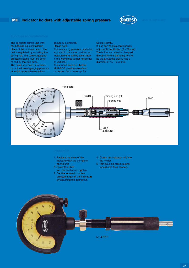
Function and installation
The complete spring unit withM2.5 threading is installed inplace of the indicator stem. The unit is regulated by adjusting the spring nut. The correct gauging pressure setting must be deter- mined by trial and error.The basic approach is to deter-mine the lowest gauging pressureat which acceptable repetition
accuracy is ensured.Please note: The measuring pressure has to be adjusted in the same position as measurements will be taken later in the workpiece (either horizontal or vertical).The knurled sleeve on holderMH4-67-F provides excellentprotection from breakage for
Series 4 BMD. It also serves as a continuously adjustable depth stop (0 – 20 mm).The holder can also be clampeddirectly into the clamping fixture,as the protective sleeve has adiameter of 15 – 0.03 mm.
Procedure 1. Replace the stem of the indicator with the complete spring unit.2. Screw the BMD into the holder and tighten.3. Set the required counter- pressure (against the indicator) by adjusting the spring nut.
4. Clamp the indicator unit into the holder.5. Test gauging pressure and repeat step 3 as needed.
MH4-67-F
27
Indicator
Holder Spring unit (FE)
Spring nut

MH10 Indicator holders with adjustable spring pressure
Holders with adjustable spring pressure should be used when-ever no indicator with the ap-propriate measuring pressure is available (see page 6) or when minimum measuring pressure is required for technical reasons (e.g. very thin walled workpiece).
77
77
MH4-67-F
MH6-65-F
28
Indicator holders with adjustable spring pressure for Series 4 BMDThe knurled sleeve (1) protects the BMDand can also be used as a depth stop.
When ordering without BMD please indicate Ø D!
With clamping fixture:
Clamping bore Order Code8H7 MH4-67-F3/8“H7 MH4-67-F-Z
Separate knurled sleeve:
for Order CodeMH4-67-F MH4-67-F-RHMH4-67-F-Z MH4-67-F-RH-Z
Indicator holders with adjustable spring pressure for Series 6 BMD
With clamping fixture:
Clamping bore Order Code8H7 MH6-65-F3/8“H7 MH6-65-F-Z

1 2 3 4 5 6 7 8 9 10 11 12
Safety through qualityElectrical probe holdersEH
The clamping unit (8) is availablein Ø 8H7 or in 3/8“H7. The probe (7) with maximum Ø 12 mm and a maximum length of 140 mm is mounted into holder and protect-ed against shocks. Once probe is installed and cable
clamped into cable guides (2), probe cable is protected againstexcessive cable bending by bend protection (1). Fine adjustment (11) by counter nut (10) can be performed to adjust probe and BMD probe.
This allows to position the probealways at the electrical zeropoint. Holders are equipped with2 marking strips as standard(version EH-V). One markingstrip can be replaced by amembrane keyboard as an option
(version EH-V-DS). This version allows to send measured values by pressing a button.
Holder configuration and installation
1. bend protection2. cable guide3. connecting ring
4. screws5. marking strips6. grip plates
7. probe8. clamping unit9. holder unit
10. counter nut11. fine adjustment12. retaining ring
The extension is ideal for applica-tions requiring measurementof deep bores in combination withelectrical probes. When using aTVT15, it is important to ensuresufficient probe cable length, asa combination with an extensioncable inside the TVT15 is notpossible.
Extension and installation for deep bore measurement
The probe (2) is inserted throughthe depth extension TVT (4) and clamped in the holder EH10-61 (1).A cable clamp TVT-EHK (5) canbe used as a cap (does not applywhen using an extension cord, asthe probe plug cannot be drawnthrough the cap).
In order to prevent jamming ofthe BMD in the bore,it is advisable to use clampablesupport rings (3) – available onrequest. For extensions and cableclamping fixtures see page 39.
1. Holder EH10-61-T15 EH10-61-T282. Probe3. Support rings4. TVT- (Page 39)5. TVT-EHK (Page 39)
29

EH Electrical probe holders
Electrical holders are used to mount transducers connected to other units, e.g. Diatron 6000, Diatron 2200 or a computer.
MH Special indicator holders
approx.18-24145approx.78
Ø33
Ø15
M6 x 0,75M10 x 1
100150
Ø32
0Ø
15-0
,03
SW13M10x1
Ø8H
7 Ø
3/8"
H7
Ø8H
7 Ø
3/8"
H7
150
120
Ø32
Ø15
-0,0
3
SW13M10x1
EH-V
EH-V-DS
MH10-150-F
L-MH10-150
30
Electrical holder with fine adjustmentM6 x 0,75 or M10 x 1 threadingHolder for transducers. The electrical zero point of transducer can be adjusted without moving it by using the external fine adjustment.
Available with suspension as an option.
Clamping bore Connection threading Order Code
8H7 M6 x 0,75 EH-V68H7 M10 x 1 EH-V103/8“H7 M6 x 0,75 EH-V6-Z3/8“H7 M10 x 1 EH-V10-Z
Electrical holder with push buttonsM6 x 0,75 or M10 x 1 threading
Type of holder with 2 push buttons for storage of measured values. One marking strip and one membrane keyboard are mounted instead of 2 marking strips. A cable can be layed onthe open end of the membrane keyboard by a zero-force connector allowing a link to a peripheral device. The requested function can be activated by pressing a button (i.e.to send the measured result). Both of the buttons are parallel-connected.
Clamping bore Connection threading Order Code
8H7 M6 x 0,75 EH-V6-DS8H7 M10 x 1 EH-V10-DS3/8“H7 M6 x 0,75 EH-V6-DS-Z3/8“H7 M10 x 1 EH-V10-DS-Z
Indicator holder with adjustable spring pressureGauging pressure of indicator can be adjusted by approx. ±1 N by adjusting and locking the two grip sleeves (1 and 2) on the holder.This is especially important for measuring of thin-walled workpieces and in order to reduce wear on the BMD contact points. The holder is ordinarily equipped with 1 marking strip.
Indicator holder, temperature stabilized, for BMD with air supply
For air hoses with an inside diameter of 3.0 mm and an outside diameter of 4.3 mm. Required air pressure: 2-3 bar.The holders are equipped with two marking strips as standard.
With clamping fixture:
Clamping bore Order Code8H7 MH10-150-F3/8“H7 MH10-150-F-Z
With clamping fixture:
Clamping bore Order Code8H7 L-MH10-1503/8“H7 L-MH10-150-Z

Safety through qualityElectrical probe holdersEH
7
EH10-61-T28
EH10-61-T15
EH-M
31
Probe holder for TVT28
This holder is suitable only for electrical probes with Ø 8H7 clamping fixtures in combination with DIATEST depth extension TVT28.
Advantage: The measurement is made by the probe on BMD itself, without influence of additional mechanical components between gauge and probe. This makes it possible to perform measurements at depths of several metres with maximum precision. Inside diameter of TVT28 is large enough to allow for connection of a probe plug and an extension cable.
Minimum bore diameter: 28.5 mm.
Probe holder for TVT15
This holder is suitable only for electrical probes with Ø 8H7 clamping fixtures in combination with DIATEST depth extension TVT15.Characteristics as for EH10-61-T28.However, no extension cables can be used inside the TVT15.
Electrical holders for multiplane plug gauges
These holders are equipped with one marking strip as standard (see page 22). Consult the table on page 23 for the appropriate model (connecting thread).
These holders are equipped with one marking strip as standard.
Model Connection size Threading G Ø D
EH-M35 x 1.5 1 M35 x 1.5 38 mmEH-M40 x 1.5 2 M40 x 1.5 42.5 mmEH-M52 x 1.5 3 M52 x 1.5 56 mm
approx.

MH Special indicator holders
7
77
Ø8H7 Ø3/8"H7
MH10-170-D
MH10-150-PG
32
Indicator holder with rotating dial
This indicator holder allows 360° rotation of the BMD in the workpiece. The measured value display remains stationary and easy to read. This holder is ideal for testing for oval or polygonal deformation.
The holder is supplied with two marking strips as standard.
Indicator holder with gauging pressure retraction
Indicator gauging pressure is removed using a bolt (1). BMD type PG (see page 8) can be inserted into the bore without contact pressure (helps to reduce wear, particularly advantageous with sensitive surfaces, etc.)
The holder is supplied with two marking strips as standard.
With clamping fixture:
Clamping bore Order Code8H7 MH10-170-D3/8“H7 MH10-170-D-Z
With clamping fixture:
Clamping bore Order Code8H7 MH10-150-PG3/8“H7 MH10-150-PG-Z
approx.

Safety through qualityANA Holder for Analodig indicators
Special holders are available forANA indicators (ANA1 and ANA- RS232).The indicator is fixedfirmly in the holder by a dual-tangent clamp.
Shifts in the position of the indica-tor are virtually impossible, evenunder heavy load conditions. Ifdifferent measurement indicatorsare used, the dimension of 41 mm must be maintained.The holders are supplied withone marking strip as standard.
It is practically impossible to shift the display accidentally with analodig holders. Adjustmentsare performed using the fine ad-justment inside the holder.Fine adjustment is secured bytightening the SW3 Allan screw (1). The adjustment range isapproximately ±1 mm.
7Ø8H7 Ø3/8"H7
AH6-140
AH10-140
AH6-61
AH10-61
33
Short holder for the Analodig indicator
Indicator holder without transfer pin
Holder for Analodig indicator
Indicator with transfer pin
Model Clamping bore Connection thread
AH6-61 Ø 8H7 M6 x 0,75AH6-61-Z Ø 3/8“H7 M6 x 0,75AH10-61 Ø 8H7 M10 x 1AH10-61-Z Ø 3/8“H7 M10 x 1
Model Clamping bore Connection thread
AH6-140 Ø 8H7 M6 x 0,75AH6-140-Z Ø 3/8“H7 M6 x 0,75AH10-140 Ø 8H7 M10 x 1AH10-140-Z Ø 3/8“H7 M10 x 1
approx.
approx.

A Adapters
BMD adapters areused to connect BMD gaugeswith smaller threads to BMD accessories with largerthreads.
Model SP: With protective bore(fracture protection for the pluggauge). Dimension X = distancebetween plane surface of plugthread and the adapter threads.
In addition to the adapters, depth extensions TV4 and TV3,8 (see Page 37) also function as adapters.
Please note: When using adapt-ers, it is important to ensure suffi-cient indicator pressure, especially with adapters for BMD series 4
Adapters for Series 4 BMD
X
A4-10-F
A4-10
A4-6
34
Series 4 to Series 10 adapterwith adjustable spring pressure
Series 4 BMD require a measuring pressure of0.3 – 0.4 N. A spring in the adapter (1) counteracts the indica-tor gauging pressure. Spring pressure can be flexibly adjusted by turning sleeve B toward threaded pin A. The sleeve (3) serves as fracture protection and as a depth stop. It can be adjusted continuously from 0 to 20.5 mm. The sleeve is se-cured with the lock nut (2). For instruction on correct adjust-ment of minimum gauging pressure see page 27.
Please indicate dimension Ø D in orders. Example: A4-10-F-D=7.2 Order Code for separate sleeve (3): A4-10-F-RH
Series 4 to Series 10 adapter
Please note: This adapter is not suitable for use withseries 10 accessories with transfer pins (e.g. TV15 orMH10-150).
X = 3
Order Code A4-10
Series 4 to Series 6 adapter
The adapter is designed to be used for BMD-PA as well.
X = 1
Adapter with supplementary fracture protection availableOrder Code A4-6-SP

Safety through qualityA Adapters
Adapters for BMD series 6
A6-6-F
A6-10-0
A6-10-L
35
Adapter for series 6 BMDwith adjustable spring pressure
The spring pressure can be adjusted flexibly by turningthe sleeve (1).The sleeve is secured with the lock nut (2). For instructionon correct adjustment of minimum gauging pressure seePage 27.
Series 6 to Series 10 adapter
Please note: This adapter is not suitable for use with Series 10 accessories with pressure pins (for instance TV15 or MH10-150).
X = 3
Adapter with supplementary fracture protection availableOrder Code A6-10-0-SP
Series 6 to series 10 adapter with transfer pin
This adapter is generally recommended for adaptingfrom Series 6 to Series 10:
• The transfer pin permits the use of all series 10 accessories.
• BMD series L
Select model A6-10-L-PA for use with BMD-PA(not shown in illustration).
X = 3
Adapter with supplementary fracture protection availableOrder Code A6-10-L-SP

W Right-angle attachments
Right-angle attachments are usedwhen working in confined spacesor for measuring lateral bores.The 90° diversion is effected withthe aid of a high-precision transferlever (2). When screwing in theBMD, it is important to ensure that the transfer lever is set in the lower position (seesketch).
The angular alignment of the pluggauge contacts (4) with the right-angle attachment (1) is notspecified.If a specific angular position is preferred please specify when ordering.
SO-W10
W10
SO-W6
W6
36
BMD with special right-angleattachment for Series 10
Use as described for SO-W6. A shorter version than theminimum length of 60 mm can be achieved by using BMDSeries 6 BMD with SO-W6.
Please note: Dimension L1 of the BMD has to be added to the length of 60 mm!
Sample order: BMD-S10-CR-28-SO-W10Also available in model L-SO-W10 (BMD with air supply)
Right-angle attachment for Series 10 BMD
Right-angle attachment LW10 has to be used with plug gauges with air supply. Order Code W10 (BMD without air supply), LW10 (BMD with air supply).
Other right angle attachments with angle 45° and 60° alsoavailable (similar version)Order Code 45º: W10-45Order Code 60º: W10-60Order Code 90º: W10
BMD with special right-angleattachment for BMD series 6If the dimensions of the BMD with right-angle attachments are too long, model SO-W6 can be used as an alternative. In this version, the right-angle attachment and the BMD are shor-tened in the area of the thread connection. The BMD and the right-angle attachment form a single unit and can be ordered as a complete set only.
Please note: Dimension L1 of the BMD has tobe added to the length of 51 mm!Sample order: BMD-S6-CR-10-SO-W6
Right-angle attachment for BMD series 6
An adapter is required for use with BMD series 4. Order Code W6
Other right angle attachments with angle 45° and 60°also available (similar version)Order Code 45º: W6-45Order Code 60º: W6-60Order Code 90º: W6

Safety through qualityTV Depth extensions
Two different types of depthextensions are available:• Depth extension with transfer pin (TV)• Depth extension without transfer pin (TVT)TV depth extensions can be usedfor measuring depths of up toseveral meters, depending on themodel.Most of the depth extensions aretemperature stabilized.
This means that temperature fluc-tuations, e.g. resulting from hand warmth, do not have a noticeable effect on the measuring results.It is important to ensure that the depth extension may not bend during the measuring process, as this will result in measuring errors.Only size TV8 (7, 8) and largerdepth extensions are used in combination.
The TV4 extension has 2 differentconnection threadings (adapterfunction).Depth extensions TV4 throughTV15 are also available withadditional pressure springs. Thisfeature may be useful where aBMD with a longerextension is used in overheadwork (the weight of the pressurepin counteracts the gaugingpressure of the indicator) requiringincreased total gauging pressure.
The spring can also be installedseparately. Order suffix: Fe.g. TV15-500-FType TVT depth extensions aresuitable for use with probes only.The probe is clamped directly tothe BMD usingEH10-61-T28 (15) holders.The power cable is fed throughthe extension (Page 39).
TV8 (7.8)
TV4 (3.8)
37
Series 6 depth extensions
TV extensions with L = 80 and above are temperature stabilized.Multiple extensions can be used in combination.
Select model L-TV8 for use with BMD with airsupply. The same dimensions apply: Example L-TV8-64
Series 4 depth extensions
TV4 depth extensions are designed for use with BMD series 4. These depth extensions cannot be used in combination. They are equipped with two different threads and thus also function as adapters (Series 4 to Series 6).
All series 4 depth extensions are temperature stabilized.
The TV4 is suitable for automatic measurement only undercertain conditions.
Ø D L A Order Code
3.8 64 79 TV3.8-64
4.0 25 40 TV4-254.0 35 50 TV4-354.0 50 65 TV4-504.0 64 79 TV4-64
Ø D L A Order Code
4.0 80 95 TV4-804.0 100 115 TV4-1004.0 125 140 TV4-1254.0 250 275 TV4-2504.0 500 525 TV4-5004.0 750 775 TV4-7504.0 1000 1025 TV4-1000
Ø D L Order Code
7.8 20 TV7.8-207.8 30 TV7.8-307.8 40 TV7.8-407.8 50 TV7.8-507.8 64 TV7.8-64
Ø D L Order Code
8.0 100 TV8-1008.0 125 TV8-1258.0 250 TV8-2508.0 500 TV8-500
Ø D L Order Code
8.0 20 TV8-208.0 30 TV8-308.0 40 TV8-408.0 50 TV8-508.0 64 TV8-648.0 80 TV8-80

TV Depth extensions
TV15-70-D
TV64-D
TV15
38
Rotary adapter for series 10
Same principle as TV64-D.With M10 x 1 connection thread.
Longer size on request.
Order Code TV15-70-D
Rotary adapter for series 6
The rotary adapter enables the BMD to rotate by 360° in the bore. The measured value display remains fixed in place. Application:bore roundness testing.
Series 10 depth extensions
These depth extensions are temperature stabilized.Multiple extensions can be used in combination.
With air supply:The TV15 for BMD with air supply is available in 2 versions:
1. with lateral air connection for hose internal Ø 3,0 Order Code L-TVA152. with air connection in threading Order Code L-TV15
L Order Code
45 TV15-4564 TV15-6480 TV15-80100 TV15-100
L Order Code
125 TV15-125250 TV15-250500 TV15-500
L Order Code
36 TV36-D64 TV64-D
approx.1
2
1
2

Safety through qualityTV Depth extensions
For measuring deep bores incombination with electronicprobes (3) and correspondinglylong cables or extensions.We recommend the use ofsupport rings (4) to facilitate
insertion into the workpiece.These rings should be approx.0.2 to 0.5 mm smaller than theworkpiece bore.The probe is clamped into theEH10-61T holder (2) (see Page
31). The probe cable runs throughthe depth extension (5) and isclamped in the TVT-EHK cableclamping fixture (6). The advantage offered by this system is that measured values
are recorded directly at the BMD (1). The risk of errors due to exten-sion bending is eliminated.
TVT15-EHK (for TVT15), Order Code TVT15-EHK
TVT28-EHK (for TVT28), Order Code TVT28-EHK
TVT15
TVT28
TVT-EHK
39
Depth extension with 15 mm outside diameterTVT15 depth extensions are used in combination with the EH10-61-T15 holder (page 31). Please note that no probe extension can be used inside the TVT, as the outside diameter of the connector is too large. A probe with a longer connection cable is required for measurement depths of more than 2 m.
Depth extension with 28 mm outside diameter
TVT28 depth extensions are used in combination with the EH10-61-T28 holder (page 31). The inside diameter of the TVT28 is large enough to permit passage of a probe extensi-on cable with coupling (outside diameter approx. 17.2 mm). The TVT28-EHK cable clamp fixture cannot be used with this option!
Cable clamp for TVT15 and TVT28
The cable clamp ensures safe withdrawalof the probe connection cable from the TVT.
Please note: The cable clamp cannot beused in combination with a probe extension cable!
L Order Code
125 TVT15-125250 TVT15-250500 TVT15-500
L Order Code
125 TVT28-125250 TVT28-250500 TVT28-500

TA Depth stops
Depth stops are used to limitmeasuring depths. They can beclamped to the correspondingdepth extension or to the holder.
Example: 1 = Indicator 2 = Holder 3 = Depth stop 4 = Depth extension 5 = BMD
TA8
TA15
TA15-A
40
Depth stop for Series 6
Can be attached to TV8 or holder MH6
Sizes:
TA8 total length 83 mmTA8-K total length 45 mm
Depth stop for Series 10
Can be attached to TV15 or MH10-
Instead of the clamping fixture, the TA15 is also availablewith M24 x 1 threading (for screw connection to TA15-C or TA15-F, for example).Order suffix: M24, example: TA15-45-M24
Depth stop for Series 10 with 3 stop pins
Can be attached to TV15 or MH10
Special version: Ø d deviating from standardOrder suffix: SO-Ød, example: TA15-A-45-SO-Ø d=32
Instead of the clamping fixture, the TA15 is also availablewith M24 x 1 threading (for screw connection to TA15-Cor TA15-F, for example).
Order suffix: M24Example: TA15-A-45-SO-Ø d = 32-M24
Ø D Order Code
45 TA15-4575 TA15-75110 TA15-110
Ø D Order Code
160 TA15-160220 TA15-220
Ø D Ø d Order Code
45 38 TA15-A-4575 68 TA15-A-75110 103 TA15-A-110
Ø D Ø d Order Code
160 153 TA15-A-160220 213 TA15-A-220

Sample application
For measuring short bores on two measuring planes (taper, etc.).
The TA15-F (1) with special depth stop ring (2) is attached to a depth extension (3).
After first measurement, theworkpiece is pressed to the endof spring stroke, and a second measurement is taken.
This unit can also be configuredas a measuring station (Page 42).Special depth stop rings availableon request.
The workpiece (4) is pulled over the BMD to the stop point.
TA15-C
TA-KW
TA15-F
TA8-F
Basic depth stop body
Can be attached to TV15 or MH10.
To be screwed onto special stop rings orTA15/TA15-A with M24 x 1 threading.Special stop rings can be produced on request.
Order Code TA15-C
Depth stop designed for clamping toBMD guide cylinders
Available versions:
• TA-KW depth stop, steel, non-hardened (standard)• TA-KH depth stop, steel with 3 carbide (HM) balls as contact points in pitch diameter TK• TA-KG depth stop, steel, hardened (Caution: increased risk of distorsion of BMD cylinder)
TA-KW depth stops can only be produced up to 100 mm!Sample order: TA-KW-15.75 (= Ø d)
Spring-loaded depth stopCan be attached to TV15 or TV8. Spring stroke is continuously adjustable from 0 to 7 mm. TA15-F can be combined with TA15-M24, TA15-A-M24 and special depth stop disks. TA8-F always has to be used in combination with special depth stop disks.Sample application: For measuring short bores on two measuring planes (taper, etc.)
Ø d Ø D TK h G
3-5 27 16 10 M45-8 30 19 10 M48-11 33 22 10 M4
11-15 37 26 10 M4
15-20 42 31 10 M420-25 50 38 12 M525-30 55 43 12 M530-35 60 48 12 M5
Ø D Ø D1 G1
30 35 M24x120 26 M18x1
G2 SW L
M4 27 88M3 22 59
Ø d Ø D TK h G
35-40 65 53 12 M540-45 70 58 12 M545-50 75 63 12 M550-60 85 73 12 M560-70 95 83 12 M570-80 105 93 12 M580-90 115 103 12 M590-100 125 113 12 M5
Order Code TA15-F (to be clamped on TV15) TA8-F (to be clamped on TV8)
G2 D1 SW
G1Ø D
L
Safety through qualityTA Depth stops
41

KM Small measuring fixtures
These fixtures are used forstationary measurements of smal-ler workpieces. One or more BMD unit can be installed.Applications: direct measurementat production machines, honingmachines, grinding machines, etc.Can be combined with standardcomponents of BMD Series 6and 10. Series 4 BMD must be adapted accordingly. A wide range of adjustment options en-sures optimum handling. Special models with longer midsections (for large BMD pluggauges) or longer side compo-nents are available on request.Clamping brackets used to mountthe KM (e.g. on a workbench) arelisted on page 42 (KM-KB). Notincluded in the delivery package.
Ø8H7
KM-MH
KM-GK
KM-KB
KM-VK
42
Indicator holder
Can be clamped directly into the KM. Without plastic grip.
Order Code KM-MH
Slotted clamping sleeve
For clamping TV8 depth extensions into the KM.
Order Code KM-GK
Clamping bracket
For mounting the small measurement fixture (e.g. on aworkbench). The Ø 8 bolt is inserted into the Ø 8.5 bore inthe KM.Not included with the KM.
Order Code KM-KB
Adjustable clamping lever
For TA15 depth stops.Facilitates rapid depth stop adjustment.
Order Code KM-VK
approx.
app
rox.

X
Safety through quality
Several KM fixtures can be combined.
Fixtures with different dimensions X (min. 30 mm) or more measurementpoints than the KM6 as well as individual components required to upgrade existing small measurement fixturesare available on request.
KM Small measuring fixtures
Sample applications
An EH can also be used insteadof a KM-MH for an inductiveprobe (Page 29). In this case, anadditional TV15 is required andclamped into the KM.
The KM-GK slotted clampingsleeve is always used as anadapter when clamping a TV8.
The W6 right-angle attachmentand matching holder are requiredfor use with BMD series 6 and a TV8.
43
Order Code X
KM1 0KM2 80KM3 80-80KM4 80-80-80KM5 80-80-80-80KM6 80-80-80-80-80

X
KM-ME Small measuring fixtures
The holder for EH-M40 x 1.5multiplane plugs can be clamped directly into the KM-ME.
The EH-M35 x 1.5 holder can onlybe clamped with the aid of aKM-ME35-40 clamping sleeve.
Special versions with longer mid-sections (for large BMD diameters)or longer side elements are available on request.
Clamping brackets for use inmounting the KM (e.g. to aworkbench), see page 42. Notincluded in the delivery package.
Small measuring fixtures for multiplane plugs
Several KM-ME fixtures can be combined.
Fixtures with different dimensions X (min. 30 mm) or more measu-rement points than the KM-ME6 as well as individual components required to upgrade existing small measurement fixtures are available on request.
Sample application
A KM-ME35-40 clamping sleeve is required for the EH-M35 x 1.5.
KM-ME35-40
44
Slotted clamping sleeve
Required for clamping the EH-M35 x 1.5 holder into the KM-ME.
Order Code KM-ME35-40
Order Code X
KM-ME1 0KM-ME2 80KM-ME3 80-80KM-ME4 80-80-80KM-ME5 80-80-80-80KM-ME6 80-80-80-80-80
approx.
app
rox.

Safety through quality
Diatest delivers measuring fixtures on customers request based on our product range.
DIAFIX Measuring fixtures
Examples
45
Fixture 1
Measuring table with space for setting master and BMD for internal and external measurement
Fixture 2
Measuring table with dial indicator holder for flatness inspec-tion
Fixture 3
Measuring table with extension and BMD for internal and external measurement
Fixture 4
Measuring table for checking of parallel distances on 2, 4 or 6 points

SH-BMD Floating holders
Floating holders (2) are used incombination with BMD type PKwith pilot taper (3) for measure-ments in fixtures. The purpose of the floating holder is to compen-sate for plug gauge positioning errors and to override minor errors in the angle between the BMD
and the bore axis.Floating holders are mounted inclamping sleeves with diametersof 20, 30 and 50 mm. They shouldnot be clamped too tightly, in or-der to avoid impairing the functionof the SH-BMD.
Floating holders SH-BMD20 andSH-BMD30 do not have antitwistprotection. When using aninductive probe, a probe spacerring is required (MUZ10).It may be necessary to removethe protective bellows in theinductive probe.
Option AT0 is recommended for applications involving frequentBMD changes (see page 8), especially with indicatorunits with inductive probes (1).
Ø8H7
Ø8H7 3/8"H7
SH-BMD20
SH-BMD30
46
Floating holder with 20 mm outside diameter
Order Code SH-BMD20-6
Technical data
Floating holder with 30 mm outside diameter
Order Code SH-BMD30-6 (connection threading M6 x 0,75) SH-BMD30-10 (connection threading M10 x 1)
Technical data
Setting the float range for SH-BMD20+30
Set the adjusting nut (A) to float range 0, but do not tighten, as otherwise the holder will be pulled backwards along with the BMD and will no longer float parallel!
Adjusting nut (A) Float range Axial tilt angle<
0 revolutions ± 0 mm 0º1 revolutions ± 0.13 mm 2º 40'2 revolutions ± 0.26 mm 3º3 revolutions ± 0.39 mm 3º 20'4 revolutions ± 0.5 mm 3º 35'
Then set the desired float range and tighten the adjustingnut with an Allan wrench. When using small-diameter BMD, it is especially important to ensure that the float range is not set too high. An excessively large float range can cause collision of the front face of the BMD.
Adjusting nut (A) Float range Axial tilt angle<
0 revolutions ± 0 mm 0º1 revolutions ± 0.125 mm 0º 30'2 revolutions ± 0.25 mm 0º 50'3 revolutions ± 0.375 mm 1º 4 revolutions ± 0.5 mm 1º 5'5 revolutions ± 0.625 mm 1º 10'6 revolutions ± 0.75 mm 1º 10'

Safety through qualitySH-BMD Floating holders
Floating holders with anti-impact protection are gene-rally used in fully automatic measuring systems. The floating holder is secured against twisting.
Models
SH-BMD50 Without air supply or fine adjustment L = 150SH-BMD50-V Without air supply, with fine adjustment L = 164±1.5SH-BMD50-L-V With air supply and fine adjustment L = 164±1.5
Applications
BMD up to nom. diameter of 150 mm with horizontal installation, BMD up to nom. diameter of 250 mm with vertical installation, BMD with Option L (with air outlet at the gauging contacts)
Fine adjustment (Type V)
In applications involving frequent BMDchanges, the probe can be calibrated to the electroniczero point on the fine adjustment unit without shiftingthe position of the probe itself.
Anti-impact protectionwith 22 mm recoil stroke
Sample applications:• Bore missing, workpiece incorrectly positioned, etc. The SH-BMD with proximity switch stops the machine if recoil is too great.• BMD moves to the bottom or step of a blind or stepped bore. The bore depth is measured additio- nally through the recoil stroke of the SH-BMD50 and a probe.• BMD-SO-KO (see page 18) is inserted into the bore to the depth stop point.
Technical description 1 Collet bore Ø 8H6 with tangential clamp for mounting the probe.2 Compressed air hose internal Ø 3,0; external Ø 4,0 (e.g. Festo PU-3)3 Collet bore Ø 8H6 for proximity switch with M8 x 1 threading in the front section4 Set screw for float range. 1 revolution = ±0.25 mm float range4.1 SW7 lock nut to secure set screw. For float range = 0: Tighten nut against the set screw, tighten adjusting screw completely.5 Weight balance spring with variable spring pressure of 4-30 N5.1 Set screw for weight balancing5.2 Spring sleeve6 Type V: The fine adjustment fixture can be adjusted by ±1.5 mm by loosening the clamping screw SW3. It is no longer necessary to move the probe for change of BMD.
Setting the float range
Tighten nut 4.1 slightly against the head of set screw 4.Tighten screw 4 to the stop point (= float range 0). Turn back screw 4 (1 revolution = ±0.25 mm float range) untilthe desired float range is set. Tighten screw 4 against nut4.1 to secure the screw against turning. The maximumfloat range is ±0.75 mm.
Weight compensation
In horizontal applications, the BMD isbalanced in the center position by adjusting set screw5.1 or replacing spring 5. This prevents excessive wearon the pilot taper when the plug is inserted into the bore.The delivery package includes 2 springs with differentstrengths. Spring 5 must be removed in verticalconfigurations.
Ø8H7
SH-BMD50
47
Floating holders with anti-impact protection

SH-BMD Floating holders
SH-BMD50-10
48
Protective sleeve for SH-BMD50
This sleeve protects the fitted electronic probe and proximity switch. The 3 cable clamps on the sleeve (for electronic probe, proximity switch and air hose) ensure all cables have strain relief and provide splash-proof protection.
Sizes
Length A Order Code
152 mm SH-BMD50-10190 mm SH-BMD50-10-190
Example
1 Proximity switch or probe2 Electr. probe3 Air hose4 Protective sleeve5 Floating holder6 BMD-PK

2
3
4
Safety through qualitySH-BMD Floating holders
The floating holder for multiplane plug gauges withanti-impact protection is designed exclusively for usewith type ME-BMD (Page 22).
Please note:Connection type 5, size 2 (see page 22) is required forinstallation of a multiplane BMD.
Weight compensation
For horizontal applications, the BMD is balanced in an approximate central position by adjusting the two set screws 4.1 or by replacing the two springs 4.The 2 set screws are positioned at an angle of 96° andmust be aligned during installation in such a way thatthey point downward and at an angle of approx. 48°to the vertical axis
Technical description
1 M8 x 1 threaded bore for proximity switch (anti- impact protection). Spring stroke approx. 20 mm2 Protective bellows to protect against splashing
3 Spring cage allows free floating. Float range approx. ±1 mm; non-adjustable.4 Weight compensation spring for horizontal appli- cations. Total of two spring sets at an angle of 96°. The springs must be positioned during installation in the machine or fixture in such a wat that weight com- pensation can be achieved. The springs must be removed for vertical installation of the SH-BMD-ME.5 Anti-twist protection. The floating holder is protected against twisting.6 3 mounting screws for multiplane BMD (3 x 120°). A type 5 connection on the BMD is required for plug gauge installation.7 Probe with Ø 8h6 extension diameter (and air hose, if applicable). The cable and hose are drawn out of the floating holder through the anti-bend protector.8 Type 5, size 2 connection (on BMD)9 Multiplane BMD10 Pilot taper
SH-BMD-ME
1
5
6
8 9 10
7
49
Floating holder for multiplane plug gauges

E Spare parts
Some BMD components are replaceable.However, it is essential to ensurethat the correct parts are used.Use of the wrong parts will resultin incorrect measurements.
Part codes:
HM-T Carbide pressure needleF F Spring (not for Series 4) FH Spring sleeve
Accessories
Accuracy of DIATEST setting rings (company standard):
Max. deviation from nom. diameter 0.0009 mmMax. concentricity error 0.0003 mmMax. rough depth 0.00002 mmHardness 62-64 HRC
HM-T
Setting rings
ZU
50
Carbide pressure needles
Pressure needles can be replaced separately. It is important to ensure that the correct pressure needles are used.Pressure needles are marked with notches.
no notch 2 notches 3 notches more than 3 notches
2-point BMD, BMD-FB6BMD-FB103-point BMDSpecial-purpose pressure needle
Setting rings are used to calibrate the measuring device. Setting rings which conform to DIN 2250-C are best suited for this purpose. They are available in all intermediate sizes from Ø 1 mm to 300 mm.Setting rings which conform to DIATEST company standards may also be used. However, these rings are available from DIATEST only in fixed diameters (from Ø 3,0 to 40,0 mm) .
Description Series 4 (M3,5 x 0,35) Series 6 (M6 x 0,75) Series 10 (M10 x 1)
HM-T Ø D L Notches Order Code Ø D L Notches Order Code Ø D L Notches Order Code
2-point 1.5 42.8 0 HM-T4 1.5 42.8 0 HM-T6 2.7 59.5 0 HM-T10FB 1.5 42.8 0 HM-T6 2.7 59.5 2 HM-T10-FB3-point 1.5 42.5 3 HM-T6-3P 2.7 58.5 3 HM-T10-3P
spring 2.5 4 F6 3.7 10 F10sleeve 2.8 6 FH4 4.5 5 FH6 7 8.5 FH10
Nom. diameter Grading Outside Height
Ø N mm mm (Ø A mm) mm
2.250 - 3.750 0.25 20.0 4.54.000 - 9.500 0.5 20.0 4.5
10.000 - 20.000 0.5 36.0 7.520.500 - 29.500 0.5 45.0 10.030.000 - 40.000 1.0 60.0 12.0
Order Code = R-nom. diameter · Sample order: R-25.500

Safety through qualityGeneral and technical abbreviations
51
Description Series 4 (M3,5 x 0,35) Series 6 (M6 x 0,75) Series 10 (M10 x 1)
HM-T Ø D L Notches Order Code Ø D L Notches Order Code Ø D L Notches Order Code
2-point 1.5 42.8 0 HM-T4 1.5 42.8 0 HM-T6 2.7 59.5 0 HM-T10FB 1.5 42.8 0 HM-T6 2.7 59.5 2 HM-T10-FB3-point 1.5 42.5 3 HM-T6-3P 2.7 58.5 3 HM-T10-3P
spring 2.5 4 F6 3.7 10 F10sleeve 2.8 6 FH4 4.5 5 FH6 7 8.5 FH10
Page Page Page
A Adapter 34-35
MHMcarbide contact points 6
SO-FB-SOBMD for stepped bores 18
ADCover 7
MKEceramic contact points 6
SO-GLBMD for longitudinalgroove measurement 18
AHHolder for Analodig indicator 33
MKKPlastic gauging contacts 7
SO-KOBMD fortapered inside diameters 18
AT0Toleranced connecting length 8
MRGauging radius 6
SO-KWBMD for crankshaft bearing width 19
BLHolder with marking strip 26
MRUruby contact points 7
SO-PABMD for parallel wall measurement 19
BLEReplacement marking strip 26
MZReduced cylinder diameter tolerance 8
SO-SZBMD with special cylinder 19
BMInspection plug 8
M24Depth stop with M24 threading 40, 41
SO-ZLBMD with extended L1 and/or L2 17
BMDPlug gauge 10-23
NHMPressure needle for BMD-PA-6 21
SO-TABMD with built-in depth stop 16
DBasic BMD type for through bores 11
NFB Pressure needle for BMD-PA-6 21
SO-WRight-angle attachment and BMDplug gauge; short form 36
D Order suffix for rotary adapter/holder 32, 38
NT-HM Pressure needle for BMD-PA-4 21
SO-2ZBMD with 2 guide cylinders 18
EH, EHTHolder for electronic probes 29-31
NT-FB Pressure needle for BMD-PA-4-FB 21
TADepth stops 40, 41
FOrder suffix fordepth extension with spring 37, 50
OCR BMD with steel cylinder(not chrome coated) 4
T-BMDBMD for small diameters 17
FBBasic type for blind bores 12
OD BMD for outside diameter 20
TVDepth extension with transfer pin 37, 38
GKSlotted clamping sleeve 42
OR BMD without pilot taper 15
TVTDepth extension without pressure pin 37, 39
HMCarbide 6
PA BMD gauge for parallel wall gauging 21
UMBMD with reduced entry diameter 15
HM-TCarbide pressure needle 50
PG BMD without inherent measurement pressure 8
VHolder or floating holderwith fine adjustment 26, 30, 47
KBClamping bracket 42
PK BMD with pilot taper 9, 14
VKAdjustable clamping lever 42
KMSmall measurement fixtures 42-44
R Gauging radius (dimension) 6
WRight-angle attachment 36
LBMD or accessorieswith air supply 13, 30, 47
Setting ring 50
ZOrder Code for 3/8” special bore 24-33
MB-BMeasurement range limitation 6
S Basic type standard BMD 10
ZHMLBMD with carbide bars 14
MB-SOMeasurement range extension 5
S-FB BMD, Type S with shortened L1 15
ZKULBMD with plastic bars 17
MCRHard chrome contact points 6
SH-BMD Floating holder for BMD PK 46-49
2RBMD with 2 guide grooves 16
MDIDiamond contact points 7
SO Special-purpose design 15-20
S0-2ZBMD with 2 cylinders 18
MEMultiplane plug gauges 22-23
SO-B Special marking 4
3PBMD in 3-point configuration 9,16
MH Indicator holders 24-28
SO-DZL BMD with extended L1 17

DIATESTHermann Költgen GmbH
Schottener Weg 6D-64289 DarmstadtGermany
Phone +49 61519790Fax +49 6151979111E-Mail [email protected]
DIATEST USA
11 West College DriveSuite I Arlington Heights, IL 60004USA
Phone +1 8003428378Fax +1 8473922197E-Mail: [email protected]
DIATEST (U.K.) Ltd.
18, Avondale Avenue,Hinchley Wood, Surrey,KT10 0DA England
Phone +44 2083981100Fax +44 2083989887E-Mail: [email protected]
DIATEST JAPAN Ltd.
15-29, 1-Chome Hitotsuya580-0003 Matsubara City, OsakaJapan
Phone +81 723306661Fax +81 723338223E-Mail: [email protected]
DIATEST Sverige
AB Hans EhlersRanhammarsvägen 24168 67 BrommaSweden
Tel.: +46 856470188Fax: +46 8362279E-Mail: [email protected]
DIATEST MEASURING INSTRUMENTS (BEIJING) CO., LTD
Room 1010, Building 61, No.1,Balizhuang Xili, Chaoyang District,Beijing,VRC
Phone +86 1085865481Fax +86 1085865483E-Mail: [email protected]
DIATEST –France S.A.R.L. Z.I. de la Malnoue, 41,Avenue de L’Europe 77184 Emerainville France
Phone +33 (0) 160951277Fax +33 (0) 160174798E-Mail: [email protected]
DIATEST do BRASIL
Produtos de Medição LTDAR. Ulisses Cruz, n° 1.050/1052 -3º.andar – CJ.06 – TatuapéZIP: 03077-000 – São Paulo – SP – Brazil
Phone +55 1120918811Fax +55 1120918801E-Mail: [email protected]
We operate a policy of continuing improvement and reserve the right to change specifications without prior notice. E.& O.E.
2013
/02/
E
QUALITY PRODUCTS – WORLDWIDE