[email protected] engr-36_lec-15_trusses-2.pptx 1 bruce mayer, pe engineering-36: engineering...
TRANSCRIPT

[email protected] • ENGR-36_Lec-15_Trusses-2.pptx1
Bruce Mayer, PE Engineering-36: Engineering Mechanics - Statics
Bruce Mayer, PELicensed Electrical & Mechanical Engineer
Engineering 36
Chp 6:Trusses-2

[email protected] • ENGR-36_Lec-15_Trusses-2.pptx2
Bruce Mayer, PE Engineering-36: Engineering Mechanics - Statics
Introduction: MultiPiece Structures For the equilibrium of structures made of several
connected parts, the internal forces as well the external forces are considered.
In the interaction between connected parts, Newton’s 3rd Law states that the forces of action and reaction between bodies in contact have the same magnitude, same line of action, and opposite sense.
The Major Categories of Engineering Structures• Frames: contain at least one multi-force member,
i.e., a member acted upon by 3 or more forces• Trusses: formed from two-force members, i.e.,
straight members with end point connections• Machines: structures containing moving parts
designed to transmit and modify forces

[email protected] • ENGR-36_Lec-15_Trusses-2.pptx3
Bruce Mayer, PE Engineering-36: Engineering Mechanics - Statics
Definition of a Truss A truss consists of straight members
connected at joints. No member is continuous through a joint.
Bolted or welded connections are assumed to be pinned together. Forces acting at the member ends reduce to a single force and NO couple. Only two-force members are considered LoA CoIncident with Geometry
A truss carries ONLY those loads which act in its plane, allowing the truss to be treated as a two-dimensional structure.
When forces tend to pull the member apart, it is in tension. When the forces tend to push together the member, it is in compression.
Tens
ion
Com
pres
sion

[email protected] • ENGR-36_Lec-15_Trusses-2.pptx4
Bruce Mayer, PE Engineering-36: Engineering Mechanics - Statics
Truss Defined Members of a truss are SLENDER and NOT
capable of supporting large LATERAL loads• i.e.; IN-Plane, or 2D, loading only• Members are of NEGLIBLE Weight
Loads MUST be applied at the JOINTS to Ensure AXIAL-ONLY Loads on Members.• Mid-Member Loads Produce BENDING-Loads
which Truss Members are NOT Designed to Support
Beams Apply RoadBed Load at
JOINTS Only

[email protected] • ENGR-36_Lec-15_Trusses-2.pptx5
Bruce Mayer, PE Engineering-36: Engineering Mechanics - Statics
Trusses Made of Simple Trusses• Compound trusses are statically
determinant, rigid, and completely constrained.
32 nm
• Truss contains a redundant member and is statically indeterminate. 32 nm
• Necessary but INsufficient condition for a compound truss to be statically determinant, rigid, and completely constrained,
nrm 2
non-rigid
32 nm
• Additional reaction forces may be necessary for a nonrigid truss.
rigid
42 nm

[email protected] • ENGR-36_Lec-15_Trusses-2.pptx6
Bruce Mayer, PE Engineering-36: Engineering Mechanics - Statics
Method of Sections
To determine the force in member BD, pass a section through the truss as shown and create a free body diagram for the left side.
With only three members cut by the section, the equations for static equilibrium may be applied to determine the unknown member forces, including FBD
When the force in only one member or the forces in a very few members are desired, the method of sections works well.
[email protected] • ENGR-36_Lec-15_Trusses-2.pptx7
Bruce Mayer, PE Engineering-36: Engineering Mechanics - Statics
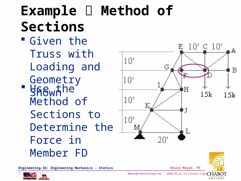
Example Method of Sections
Given the Truss with Loading and Geometry Shown
Use the Method of Sections to Determine the Force in Member FD

[email protected] • ENGR-36_Lec-15_Trusses-2.pptx8
Bruce Mayer, PE Engineering-36: Engineering Mechanics - Statics
Example Method of Sections
Take Section to Expose FFD
Now Take ΣME = 0
''' 1020kip1510kip150 FDF
kip45
10ft
ftkip300150
FDF nCompressio kip45FDF

[email protected] • ENGR-36_Lec-15_Trusses-2.pptx9
Bruce Mayer, PE Engineering-36: Engineering Mechanics - Statics
Example Method of Sections
Determine the force in members just right of Center: • FH • GH • GI
SOLUTION PLAN• Take the entire truss as a free
body. Apply the conditions for static equilibrium to solve for the reactions at A and L.
• Pass a section through members FH, GH, and GI and take the right-hand section as a free body.
• Apply the conditions for static equilibrium to determine the desired member forces.

[email protected] • ENGR-36_Lec-15_Trusses-2.pptx10
Bruce Mayer, PE Engineering-36: Engineering Mechanics - Statics
Example Method of Sections SOLUTION PLAN
• Take the entire truss as a free body. Apply the conditions for static equilibrium to solve for the reactions at A and L
kN 5.12
kN 200
kN 5.7
m 30kN 1m 25kN 1m 20
kN 6m 15kN 6m 10kN 6m 50
y
yy
A
A
ALF
L
L
M

[email protected] • ENGR-36_Lec-15_Trusses-2.pptx11
Bruce Mayer, PE Engineering-36: Engineering Mechanics - Statics
Example Method of Sections Pass a section (n-n) through
members FH, GH, and GI and take the right-hand section as a free body
Apply the conditions for static equilibrium to determine the desired member forces.
kN 13.13
0m 33.5m 5kN 1m 10kN 7.50
0
GI
GI
H
F
F
M
TFGI kN 13.13

[email protected] • ENGR-36_Lec-15_Trusses-2.pptx12
Bruce Mayer, PE Engineering-36: Engineering Mechanics - Statics
Example Method of Sections
kN 82.13
0m 8cos
m 5kN 1m 10kN 1m 15kN 7.5
0
07.285333.0m 15
m 8tan
FH
FH
G
F
F
MGL
FG
CFFH kN 82.13
kN 371.1
0m 15cosm 5kN 1m 10kN 1
0
15.439375.0m 8
m 5tan
32
GH
GH
L
F
F
M
HI
GI
CFGH kN 371.1

[email protected] • ENGR-36_Lec-15_Trusses-2.pptx13
Bruce Mayer, PE Engineering-36: Engineering Mechanics - Statics
Method of Sections - Summary1. If needed Determine Support Reactions
2. Decide on How to CUT the Truss into Sections and draw the Corresponding Free Body Diagrams
3. Try to Apply the Eqns of Equilibrium to avoid generation of simultaneous Eqns
• Moments should be Summed about points that lie at the intersection of the LoA’s of 2+Forces, making simpler the solution for the remaining forces

[email protected] • ENGR-36_Lec-15_Trusses-2.pptx14
Bruce Mayer, PE Engineering-36: Engineering Mechanics - Statics
Pick: Pivot & PoA
When doing Sections Recall that the LoA for Truss Members are defined by the Member Geometry
Use Force Transmissibility → Forces are SLIDING Vectors• Pick a Pivot Point, on or Off the Body,
where the LoA’s of many Force LoA’s Cross• Apply the Force of interest so that ONE of
its X-Y Components passes Thru the Pivot

[email protected] • ENGR-36_Lec-15_Trusses-2.pptx15
Bruce Mayer, PE Engineering-36: Engineering Mechanics - Statics
Pick: Pivot & PoA Example
After Finding support RCNs find force in Member ED → Use Section a-a
Pick Pt-B as Pivot to Eliminate from Moment Calc FAB, FFB, FEB, 1000N

[email protected] • ENGR-36_Lec-15_Trusses-2.pptx16
Bruce Mayer, PE Engineering-36: Engineering Mechanics - Statics
Pick: Pivot & PoA Example
Pick Pt-C as the Point of Appliction (PoA) for FED
Using Pt-C as the PoA permits using F•d to find the Moment about Pivot-B

[email protected] • ENGR-36_Lec-15_Trusses-2.pptx17
Bruce Mayer, PE Engineering-36: Engineering Mechanics - Statics
WhiteBoard Work
Let’s WorkSome TrussProblems
Find Forces in EL & LM
Find Forces in EL & LM

[email protected] • ENGR-36_Lec-15_Trusses-2.pptx18
Bruce Mayer, PE Engineering-36: Engineering Mechanics - Statics
Bruce Mayer, PERegistered Electrical & Mechanical Engineer
Engineering 36
Appendix

[email protected] • ENGR-36_Lec-15_Trusses-2.pptx19
Bruce Mayer, PE Engineering-36: Engineering Mechanics - Statics