bm330 service manual - ljungberg & kögel abljungberg-kogel.com/pdf/bm330_service_manual.pdf ·...
TRANSCRIPT

BM 330 Service Manual Rev 2012-11-13
BIOMIXER
BM330
Service Manual
Ljungberg & Kögel AB

This page is intentionally left blank

Important This Service Manual is written for the service personnel (technicians) responsible for service and maintenance of Biomixer BM330. It gives a detailed description about the BM330 soft- and hardware, explaining how it works and how to run the built-in testprogram.
Note! It is important that the service personnel has been trained and approved by Ljungberg&Kögel before opening the instrument or making any repair operation, if not, the warranty may be invalid.
L&K recommend exchange of complete parts as specified in "Spare Parts List" in Operator's Manual instead of replaceing discrete components.
For operating instructions and Spare Parts List see BM330 Operator's Manual. Abelko Innovation is committed to develop high-quality equipment and technical services to all our customers. We welcome any inputs on technical issues that are encountered so that they can be resolved quickly and in the most appropriate manner. Please submit your comments/feedbacks through your local distributors or alternatively email us directly at [email protected]

Table of contents Important ................................................................................................................................................................. 3 Table of contents ..................................................................................................................................................... 4 General technical description. ................................................................................................................................. 6 Detailed technical description. ................................................................................................................................ 6 Software .................................................................................................................................................................. 6
Development environment .................................................................................................................................. 6 Memory allocation .............................................................................................................................................. 6
Setup ............................................................................................................................................................... 6 Data ................................................................................................................................................................. 6
Functional description ............................................................................................................................................. 7 Basic program components block diagram ..................................................................................................... 7 Start, initialization after power on ................................................................................................................... 9 Driving the AC-motor ..................................................................................................................................... 9 Driving the clamp .......................................................................................................................................... 10 Battery capacity............................................................................................................................................. 10 Weighing, reading the A/D ........................................................................................................................... 10 Scanning the keyboard .................................................................................................................................. 10 Updating the display ..................................................................................................................................... 10 Reading the RTC ........................................................................................................................................... 10 Automatic taring ........................................................................................................................................... 10 Buzzer volume .............................................................................................................................................. 10 Setup ............................................................................................................................................................. 10 Calibration ..................................................................................................................................................... 11 Data storing and sending ............................................................................................................................... 11
Program verification ......................................................................................................................................... 11 General .......................................................................................................................................................... 11 Simulation of the target system ..................................................................................................................... 11 Emulation on Nohau EMUL51 ..................................................................................................................... 11 Prom testing .................................................................................................................................................. 12
Hardware ............................................................................................................................................................... 12 Microprocessor and memory ......................................................................................................................... 12 Data backup .................................................................................................................................................. 12 Serial synchronous bus (SPI) ........................................................................................................................ 12 I/O ports ........................................................................................................................................................ 12 Tray motor movement control ...................................................................................................................... 12 "Home" switch .............................................................................................................................................. 12 LCD contrast potentiometer .......................................................................................................................... 13 Buzzer volume .............................................................................................................................................. 13 Clamp linear stepmotor driver ...................................................................................................................... 13 Load cell and amplifier ................................................................................................................................. 13 RS232 serial communication port ................................................................................................................. 14 RS485 serial communcation port .................................................................................................................. 14 External display............................................................................................................................................. 14 Power supply and voltage regulators ............................................................................................................ 14
Running the testprogram ....................................................................................................................................... 15 1 Displaytest. ..................................................................................................................................................... 15 2 Keyboardtest. ................................................................................................................................................. 15 3 Offset (zero) calibration. ................................................................................................................................ 15 4 Gain calibration and adjusting........................................................................................................................ 16 5 Clamp test. ..................................................................................................................................................... 16 6 Motor and "home" position sensor test. ......................................................................................................... 16 7 Battery test. .................................................................................................................................................... 16 8 Setting of buzzer volume. .............................................................................................................................. 16 9 Test of external display outport. ..................................................................................................................... 17 10 Communication test RS232. ......................................................................................................................... 17 11 Communication test RS485. ......................................................................................................................... 17

12 Clocktest. ..................................................................................................................................................... 17 13 RAM-test. ..................................................................................................................................................... 17 14 EEPROM-test............................................................................................................................................... 18 15 EPROM-test. ................................................................................................................................................ 18
Special memory commands .................................................................................................................................. 18 Data memory clear ............................................................................................................................................ 18 Data and setup memory clear ............................................................................................................................ 18
Dismounting the BM330 ....................................................................................................................................... 19 Circuit diagram ..................................................................................................................................................... 20 Component placement ........................................................................................................................................... 21 Test protocol (Production final test)...................................................................................................................... 21 Test protocol (Production final test)...................................................................................................................... 22

General technical description. BM330 is controlled by an 8 bit microprocessor 8052 with external 64 kbyte prom for program execution and 32kbyte CMOS RAM for data storage. A realtime watch (RTC) Dallas DS1302 keeps the time and date. All settings, ID, calibration constants etc. are stored in a non-volatile serial Eeprom. A backup super capacitor keeps the data RAM and RTC with power when internal battery is flat or during exchanging.
It is powered by an internal lead-acid battery 12V/3,5Ah and the battery is recharged with an external battery charger with a constant voltage of 14.0VDC and maximum current 0.8A.
The weighing is done by a loadcell, and a bridge amplifier amplifies the signal and an A/D-converter converts the analog signal to a digital 12 bit word which is serially read by the CPU.
The mixing tray is operated by an AC-driven synchronous motor. The 50Hz AC is generated by software in the CPU and transformed to 24VAC waveform by a transformer.
The clamp is operated by a linear stepmotor controlled by a controller IC TCA 3727.
The keyboard is a membrane key matrix and the display is a 2x20 LCD with internal character generator.
There is one RS232 serial communication port for a PC or a barcode reader and one RS485 port for LAN communication with up to 31 mixers connected together, transmitting collected data to a registration PC.
Optionally an external display with large figures for collection volume can be connected to the mixer.
Detailed technical description.
Software
Development environment The program is written mainly in ANSI C, with MCU specific extensions for Intel 8051 family. Compiler is IAR:s ICC8051, ver 5.12H. Assembler is IAR:s A8051, ver 2.03. Linker is IAR:s XLINK, ver 4.46L. Debugging has been done using Nohau’s Emul51 emulator, but also by using a special program version compiled for Borland TurboC ver 3.00, containing software simulation of some of the hardware.
Memory allocation
Setup Non volatile setup parameters are saved in EEPROM memory. Each time a parameter is changed and the menu is left, the parameter is saved to EEPROM and a new checksum is calculated on the entire EEPROM memory. Setup parameters can be viewed or changed in the setup or test menus only. When the program is started, the EEPROM area is mirrored to RAM-memory for easy and fast access. If a checksum mismatch is discovered during this process a setup error message is displayed and default parameters are used.
Data Information concerning each collection is saved in capacitor (BUC) backuped RAM memory. This memory is not checksum protected, but an area is reserved for a ”sentinel” value that is used to determine if data has been lost, due to a long period without mains or battery supply. If the memory should be detected as lost during startup it is erased and the sentinel value reinitialized. During this erase a hardware RAM check is also performed, and a data error message is displayed. Hardware RAM check can also be done in the test menu. If the memory is lost during operation, a data error message is also displayed, but the memory is not erased until a restart is done.

If a powerfail should occur during a critical write of data, i.e. increase of an index value that isn’t written in an atomic process, it could result in scrambled data. To prevent this the external watchdog circuit generates an early warning high priority powerfail interrupt. Prior to each critical writes of data the powerfail interrupt is disabled, the write is done, and the interrupt is enabled again. The interrupt routine is simply a delay that prevents the normal program to run until the voltage is lost. This ensures that a critical write is made in an atomic, uninterruptable process.
Functional description
Basic program components block diagram
Initialization
Continued collection (If powerfail during collection) See NEW or START at level prior to powerfail
Test program
SETUP (boot) – Start test program
Erase memory program
NEW + SETUP (boot) – Start EEPROM + RAM erase program
NEW + RESET (boot) – Start RAM erase program

Main program
NEW – Start new barcode collection
START – Start new collection
SETUP – View and change setup parameters
INC / DEC – Change current preset volume
SET – Toggle between 2 preset volumes
SEND – Send collection information to PC-program
CLAMP – Open/close clamp
RESET – Park the tray
PAUSE – Continuos measuring without registration
Scan barcodes
Collect blood
Collection ready
Scan barcodes
Send collection data
Collect blood
Collection ready
Send collection data

Start, initialization after power on At power on system registers are initialized, i.e. stack pointer etc. Then the display is initialized and the text ”Initializing…” is displayed during further startup procedure. BUC backuped RAM memory is tested and re-initialized if lost. C-variables are initialized. EEPROM parameters are mirrored to RAM or set to default values if a checksum error was discovered. If erasing memory should be done on keyboard boot command it is done now. Electronic potentiometers are initialized. Clamp is initialized. If continued measuring should be done due to powerfail it is done now. The tray is moving one mixing cycle. If function testing should be done on keyboard boot command it is done now, otherwise the standard menu is displayed. The program is now ready for keyboard commands.
Driving the AC-motor The AC-motor, used for tray mixing cycles, is managed by an interrupt routine which generates 50 Hz pulses. If, for some reason, the motor wheel never reach its home position (tray jammed etc.) a motor error is displayed.
Sub programs
Keyboard scanning (irq)
Display driver
Tray AC-motor driver (irq)
Clamp step-motor driver
A/D routines and measuring
External display driver
Serial communication (irq)
Configuration
Barcode reader
Collection data
Error handler EEPROM routines
Electronic potentiometer routines
Buzzer level
Taring
RTC routine
Timer routines (irq)
Powerfail routine (irq)

Driving the clamp The clamp is operated by a stepmotor which is controlled by a program subroutine. At power up, the clamp is reset by setting its position counter to ”closed” (despite its actual position) and then run it to ”open”. If the clamp was already open this operation will have no effect, but to make sure for the program that the position is indicated correctly.
Battery capacity The battery capacity is constantly monitored each 5 seconds, except for the moments when the tray motor is running. If the capacity is too low another collection cannot be started, but the current one can be finished.
Weighing, reading the A/D The A/D converter is used to read the amplified value from the loadcell on one channel. The other channel is used to measure battery voltage. The loadcell value is converted to volume or weight, due to how it is calibrated. During collection, the filtered difference between values at each weighing cycle is also converted to flow per minute.
Scanning the keyboard The keyboard is scanned on interrupt and saved in a keyboard buffer. If a key is pressed longer than 0.5 seconds it is repeated. The keyboard buffer is then polled each program loop.
Updating the display The display is initialized during startup. At each program loop the display buffer is written to the display.
Reading the RTC The RTC (Real Time Clock) is read every new second in the program loop. The clock value is used for timestamp collection data and keep track of collection time, collection alarm intervals etc. If the time read from the RTC should be invalid a clock error is displayed.
Automatic taring Prior to each collection an automatic taring sequence is performed. It is done by adjusting the electronic potentiometer for taring until the relative volume (with empty bloodbag on tray) reads 0 ml. (The absolute volume is then about 100 ml if adjusted and calibrated correctly. This means the relative volume can show negative values down to –99 ml). If the relative value of 0 ml for some reason cannot be reached a tare error is displayed. The manual offset adjustment in the test menu is done to give the electronic potentiometer the maximum possible range at each direction.
Buzzer volume Buzzer volume is set in the setup menu. It is controlled by an electronic potentiometer which can be set to values between 0 to 31. Note that a value less than 12 may cause the buzzer to stop beeping.
Setup In the setup menu a number of non volatile EEPROM parameters can be viewed and changed. Each time a parameter is changed and the menu left, the parameter is saved to EEPROM and a new checksum is calculated. If the EEPROM has a faulty checksum during initialization a setup error is displayed.

Calibration The calibration sequence in setup menu is done to establish the coefficient for converting A/D bit value to volume (or weight). This is done by first perform a tare to establish zero point and then adding a weight of 472g to calibrate for bit value to volume.
Data storing and sending Collection information, including barcode readings, are stored in BUC backed RAM. It can be transmitted to the information PC at the end of each collection, or at a later time.
Program verification
General • Programming. • Simulation of the target system in Borland C. • Emulation on Nohau EMUL51. • PROM-testing.
Simulation of the target system Each menu and as much as possible of other functions has been tested during development to find as many bugs as possible during an early stage. This has been done by compiling a program version for simulation, where keyboard and display has been redirected to a PC keyboard and monitor. This simulation tests includes: • All menus, except erase memory. • Error handling, by introducing faked error conditions. • Barcode reading by introducing faked barcode messages. • Display routines, at high level. • Keyboard routines, at high level. • Change preset collection volume.
Emulation on Nohau EMUL51 To test routines that isn’t easy to test with a simulation program, and to catch bugs in all code segments and in hardware, an emulation test has been done: • Communication from configuration PC by receiving configurations. • Communication from barcode reader by receiving barcodes according to
different configurations. • Communication to collection PC by sending collections. • Communication (general) by running test program for communication. • Collection test by applying 5g weights until the different collection modes has been reached. This includes
test of flow alarm, time alarm and measuring. • Setup memory test, by using memory test routines and checking that values remain after powerfail. • Clamp motor function by visual inspection in program and test routines. • Tray motor function by visual inspection in program and test routines, and by preventing the wheel to reach
home position (motor error test). • Memory erase programs, by running them and check result in emulator memory and setup menu parameter
values. • Powerfail interrupt, by variable input voltage and setting a breakpoint in the interrupt routine. • Battery capacity, by variable input voltage and compare display readings to voltmeter readings. • RTC, by setting and reading time in test menu and collection menu. • Timer interrupt, by breakpoint settings and time measuring between breakpoints. • External display, by measuring on CPU pins when running its test program. • Taring, by compare measured values from voltmeter (A/D-level and electronic potentiometer level) with
theoretical expectations.

• Calibration, by comparing measured values from voltmeter (A/D-level) with theoretical expectations. • Stack check, by emulator memory control.
Prom testing • Every menu and program mode has been executed. • Two bloodbags connected with a tube, of which one contained colored liquid with the
density of blood, has been used to simulate donations.
Hardware See schematics on page 20
Microprocessor and memory BM330 is controlled by an 8 bit microprocessor 8052 with external 64 kbyte prom for program execution and 32kbyte CMOS RAM for data storage. The oscillator runs on 11.0592 MHz, a frequency choosen to suit communication bit rate generation by internal timers.
Data backup Data CMOS RAM have low standby current < 1uA/ 3.5V and is, together with the RTC, back-uped by a 0.1F super capacitor C19. The battery switchover circuit IC20 (Max 691A) automatically switch over to backup capacitor when +5Vcc supply drops below 4.6V. During this time IC20 also turns off chip select signal CERAM to avoid accidently writing in RAM during power down. IC 20 also senses the battery voltage before the 5V-regulator to get an early warning on Pfail output when power is disappearing. This PFAIL signal is connected to the highpriority INT0 interupt to the CPU.
Serial synchronous bus (SPI) A serial bus with SOUT, SIN, SCLK is used to communicate with the 12 bit A/D-converter IC5, serial EEPROM IC18, where the setup and calibration parameters are stored, the RTC IC19, the electronic potentiometers IC4 for offset adjustments and IC 17 for buzzer volume and finally the optional external display. It runs with ca 500kbps clockpulses and each circuit (function) is selected by the chip-select decoder IC6 selecting CSPOT, CSEXT, CSBIP, CSAD, CSE2 and CSCLK respectively with CPU pin P1.0, P1.1 and P1.2 giving the address.
I/O ports There are 4 parallell I/O-ports connected to the databus. IC12 is an outport for buffering data written to the display together with the buffered signals A0, A1 and OUTAX. IC 13 is an inport for reading the keyboard matrix scanned with outport IC14. IC14 also turns on and off the buzzer and gives the 50Hz signals to the AC-driven asynchronous motor for tray movement. IC15 is the outport for the stepmotor controller IC16. The chip-select signals to all this I/O-ports are created by IC8 and are memory mapped for adresses above RAM adress, i.e. from 8xxxH.
Tray motor movement control The 50 Hz driving the AC-motor is generated by the IC14 pin 5,19 signals MD1,MD2. They are pulsing 50Hz with a phase difference of 180 dgr. Transistors T1 and T2 are amplifiers and level converters and transformer TR1 transform the 12V signal on the primary side to 24 VAC at the secondary side, driving the motor. The 3:rd phase is generated by the bipolar capacitor C30.
"Home" switch A reed switch mounted on the motor plate works as a position sensor and are actuated by a small magnet glued in a hole in the driver wheel. When the driver wheel enters the "home position" where the tray goes free from the roller, i.e. is in the weighing position, the switch is closed by the magnet and the signal is read by the inport IC13 and signals to the CPU which immediately stops the motor and makes a weighing. See spare parts list in Operator's Manual for mechanical details.

LCD contrast potentiometer The LCD contrast can manually be adjusted with the potentiometer TP3.
Buzzer volume Volume level is adjusted by an electrically programmed potentiometer and adjustments are made from "Setup menu", see Operator's Manual for details. The Eepot is controlled by the SPI-bus.
Clamp linear stepmotor driver The clamp is controlled by a linear stepmotor which is driven by IC16, a Siemens TCA3727 driver. For the clamp to close properly the distance from the top to the base must be 55.0-55.5 mm in closed position, i.e. max out, se picture below:
Load cell and amplifier
Load cell 325-3 is a full bridge cell given a signal of ca 1.5 mV/Kg. The origin offset (built in offset from loadcell production) is manually adjusted with the potentiometer TP1 to a level from A/D-converter corresponding to ca 100 ml (ca 360 mV measured at IC5 pin 4) at production test. During this adjusting the electronically controlled potentiometer IC4 is in the middle (neutral) position. When BM330 makes the taring process it adjusts the IC4 potentiometer back to ca 100ml. (This is done with the empty bloodbag on the tray). This value is then referred to as the zero-value and deducted from the continous readings when the blood is collected.
The reason for this electrically adjustment of balance is to give a very dynamic adjustment range insensible of tare weight or if the loadcell has been deformed by tough treatment during transportation or otherwise.
The amplifier consist of two op-amps connected in a way that eliminates the input offset voltage and has a gain that gives a 0-5V signal for a weight of ca 0-1360g. The gain can be adjusted by potentiometer TP2 and adjustments should be made according to instructions in the Operator's Manual. See also testprogram number 3 and 4 in this manual.
The loadcell is protected by stopscrews for both lifting and pressing overloading. The upper stopscrew shall be adjusted to 0.1mm distance and the lower stopscrew shall be adjusted to 0.2 mm, use a thickness gauge for measuring. Adjustments can be done with the loadcell loosened or with the PC-board loosened. The lower stopscrew is accessible from a hole in the chassis bottom plate. See figure below:
Adjust to 55mm. -0+0.5

RS232 serial communication port This port is used for the barcode reader with the power supply +5V and gnd connected to p9 and p5 in the 9-pole male dsub connector. See complete wiring in BM330 Operator's Manual. It is very important that the used barcode reader has a compatible connection, otherwise the mixer or the barcode reader may be damaged. The barcode reader current consumption must be max 60mA in average or else the battery operation time will be reduced.
Note! Always use barcode-readers recommended by Ljungberg&Kögel
The RS232 port is also used by the configuration PC when setting up the mixer for network operation. See Operator's Manual for details.
RS485 serial communcation port This port is a multidrop LAN "Local Area Network" connector for connecting 1-31 mixers together in a LAN to a common registration PC for registration of blood collections. It follows the RS485 standards and the connector is a RJ12. See Operator's Manual for network details.
External display The connector is a RJ12 connector with +12V power out and parts of the SPI-interface, SOUT, SCLK and CSEXT . Information to the display is shifted out in a serial bitstream with ca 500kbps once a second.
Power supply and voltage regulators The mixer is powered by an internal lead-acid battery of 12V/3.5Ah recharged by an external constant battery charger. The battery charger can supply the mixer even if the battery is flat or if the battery is removed. Battery voltage is measured by the A/D coverter and remaining power is shown on display during power up. Note! When battery charger is connected the remaining power will always display 99%. The battery is supplying the backup capacitor with a small maintenance current to keep the RTC and RAM with power during storing and transportation and the battery is protected from being completely emptied by the zener diode Z1. The maintenance current drawn from the battery is less than the battery selfdischarge current. Wires and components are protected from hazardious current flow in case of a shortage by a selfrecovery PTC termistor PTC1. There are two voltage regulators: REG1 for +5V digital supply and REG2 for +5V analog supply, to avoid digital noise in the measuring circuits. The groundplane is also separated in an analog groundplane, marked with a dotted line in amplifier section of circuit diagram, and a digital groundplane for the rest of PCB.
Upper stopscrew 0.1mm
Lower stopscrew 0.2mm

Running the testprogram A built in testprogram can be run to verify BM330 functions. The testprogram is started when the SETUP key is pressed during power up.
When testprogram has started ( takes about 3-4 seconds) the display shows:
With ”+” and ”-” keys you can choose Automatic or Manual test. Confirm with a press on SETUP. A press on RESET ends the testprogram and the ordinary main menu is shown.
If Automatic test is selected the test sequence will immediately start with test1: Displaytest, and continoue with the next test after a new press on SETUP. When all 15 tests are done you will be back to the startmenu as above.
If Manual test is selected with the press on SETUP, you can now select the testno. with the keys "+" and "-" and confirm with SETUP. The testnumbers are listed below for respective testfunction. Testfunction ends with a press on SETUP and a new Manual test number can be selected with the keys "+" and "-" or continoue with the next test by pressing SETUP. Manual test is ended with a press on RESET and the ordinary main menu is shown.
1 Displaytest. All segments of row 1 are turned on in 0.5 sec and then all segments on row 2 are turned on alternately. The test is done to verify that display and connections are ok. If necassary the contrast can be adjusted, see Operator's Manual for details. The test is ended with SETUP
2 Keyboardtest. Keyboard is checked by pressing each key and the display shows the key function. End by pressing ”NEW” and ”SETUP” simultaneous.
3 Offset (zero) calibration. This is a check of the loadcell origin offset adjustment done with the inside potentiometer TP1. The electronic potentiometer IC4 is programmed in the middle position (after pressing START) and the value shown on the display should be ca 0-200 with the empty tray on the loadcell shaft. TP1 can be adjusted (the cover must first be lift off) to the nominal value +100 ± 5 ml. The value on display is the actual weight coverted to ml (/1.06) affecting the loadcell and is continuously updated.
Note! This origin offset adjustment is normally only need to be done when the loadcell has been replaced or if it has got a hard blow making it change the value radical, there is no need to readjust TP1 if the value is 0-200 for the weight of the empty tray. End with SETUP.
TEST AUTOMATIC
3 CALIBRATION OFFSET PRESS START
TEST MANUAL 1 DISPLAY TEST
####################
2 KEYBORD TEST SETUP
TEST MANUAL
3 OFFSET VALUE 95 (100)

4 Gain calibration and adjusting. Gain calibration starts with an automatic taring (after pressing START) and then the weight on the tray is showed on display. Put the reference weight of 450ml (477g) on the tray with the opening in the reference weight placed over the positioning peg on the tray for best accuracy.
Note! Always use reference weights from Ljungberg&Kögel for best accuracy.
The reading should be 450 ± 5% but notice that the reading is the rough value without the software automatic calibration!
If out of limits adjust the GAIN potentiometer TP2 until the reading is 450 ± 5ml, remove the reference weight and make a new taring by pressing SETUP-“–“ (to go back to GAIN calibration menu) – SETUP and after that START again. Put the reference weight back and repeat adjustment until the value is within ± 5ml. End with SETUP.
Note! Always end with automatic calibration, without maually adjusting the gain, to get the correct sofware calibration factor. See Operator's Manual Setup functions "Calibration".
.
5 Clamp test. This test closes the clamp, waits 0.5 sec and then opens the clamp, waits 0.5 sec and so on. Check that the closing is complete.
Note! Never leave the test in this mode for a longer time i.e. more then 10 minutes, since the step motor will get overheated and may be damaged.
Test is ended by SETUP and the clamp will be left open.
6 Motor and "home" position sensor test. One mixing cycle is done, then a stop in the weighing position for ca 0.5 sec, a new cycle is done, stop, and so on. Check that the motor with the gearbox is running nice and smootly. Test is ended with SETUP.
7 Battery test.
This test shows the battery voltage on display. The measuring accuracy is ± 0.1V and can be adjusted with TP4.
8 Setting of buzzer volume. This test checks the electronic potentiometer IC17 and the buzzer connection. The potentiometer is programmed in its middle position (15) and the buzzer starts beeping when ”+”or ”-” is pressed. Check that the volume can be
4 CALIBRATION GAIN PRESS START
5 CLAMP TEST CLAMP OPEN
6 MOTOR TEST
7 BATTERY 12.00
GAIN VALUE 0 (450)
increased with "+" and decreased with "-" and the last value programmed when leaving this test will be the set buzzer volume.
Note! Setting too low value, <12, may cause the buzzer to stop beeping.
Test is ended with SETUP.
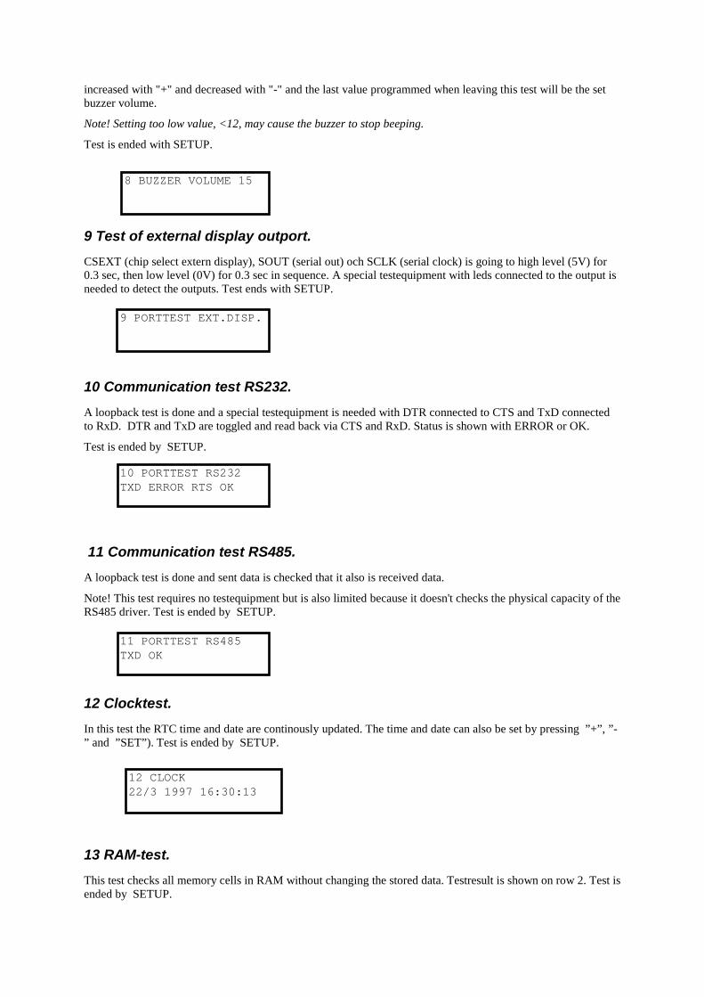
9 Test of external display outport. CSEXT (chip select extern display), SOUT (serial out) och SCLK (serial clock) is going to high level (5V) for 0.3 sec, then low level (0V) for 0.3 sec in sequence. A special testequipment with leds connected to the output is needed to detect the outputs. Test ends with SETUP.
10 Communication test RS232. A loopback test is done and a special testequipment is needed with DTR connected to CTS and TxD connected to RxD. DTR and TxD are toggled and read back via CTS and RxD. Status is shown with ERROR or OK.
Test is ended by SETUP.
11 Communication test RS485. A loopback test is done and sent data is checked that it also is received data.
Note! This test requires no testequipment but is also limited because it doesn't checks the physical capacity of the RS485 driver. Test is ended by SETUP.
12 Clocktest. In this test the RTC time and date are continously updated. The time and date can also be set by pressing ”+”, ”-” and ”SET”). Test is ended by SETUP.
13 RAM-test. This test checks all memory cells in RAM without changing the stored data. Testresult is shown on row 2. Test is ended by SETUP.
9 PORTTEST EXT.DISP.
10 PORTTEST RS232 TXD ERROR RTS OK
11 PORTTEST RS485 TXD OK
12 CLOCK 22/3 1997 16:30:13
8 BUZZER VOLUME 15

14 EEPROM-test. This test checks all memory cells in EEPROM without changing the stored data. Testresult is shown on row 2. Test is ended by SETUP.
15 EPROM-test. This test calculates the checksum for EPROM and shows it on the display. The value should be the same as marked on the EPROM label. Test is ended by SETUP.
Special memory commands The following memory commands can be useful if there has been scrambled data in memory causing the BM330 to fault or misfunction, e.g. problem with starting up.
Data memory clear Data memory (RAM) is cleared by pressing NEW and RESET during power up. Display will show: A press on RESET will erase all data memory. Warning! All collected data will be lost.
Data and setup memory clear Data (RAM) and Setup (EEPROM) memory is cleared by pressing NEW and SETUP during power up. Display will show: A press on RESET will erase all data memory and setup memory. Warning! All setup data e.g. flow alarm, time alarm, etc. will be set to default values. All configuration data will be lost and has to be reprogrammed and a new calibration must be done.
13 MEMORYTEST RAM OK
14 MEMORYTEST EEPROM OK
15 MEMORYTEST EPROM xxxx
ERASE DATA? YES:RESET NO:SET
ERASE SETUP+DATA? YES:RESET NO:SET

Dismounting the BM330 1. Loosen the 2 screws holding the tray, and lift
off the tray.
2. Loosen the screw with roller.
3. Loosen the 4 screws holding the cover, marked
with arrows on figure. Lift off the cover.
Loosen 2 screws

Circuit diagram

Component placement

Test protocol (Production final test) This is the test protocol used for the final test in factory. This document is referring to the BM330 test procedure. Date Name Serial number Reference: BM 330 test procedure § Description Read value OK ERR Remarks 1 Factory software version 2 Check of basic functions 3 Cover, tray assembly 4,5 Overload and seesaw motion 6 Calibration,tare before burn-in 7 Burn-in 8 Tare drift after burn-in (ml) 6.1 Display 6.2 Keyboard 6.3 Offset 6.4 Gain 6.5 Clamp 6.6 Motor 6.7 Battery 6.8 Buzzer 6.9 External display output 6.10 RS-232 6.11 RS-485 6.12 Clock 6.13 RAM 6.14 EEPROM 6.15 EPROM 10 Calibration after burn-in 12,13 On line registration 14 Custom install 15 Check calibration (ml) 16 Final inspection 17 Type plate

This page is intentionally left blank

Ljungberg & Kögel AB