bluetooth® low energy (v5.0) rf-test for internet of things ... · bluetooth® low energy (v5.0)...
TRANSCRIPT
Bluetooth® Low Energy (V5.0) RF-Test for Internet of Things Applications Application Note
Products:
ı R&S®CMW500
ı R&S®CMW290
ı R&S®CMW270
ı R&S®FSVxx
ı R&S®FSVAxx
ı R&S®FSWxx
ı R&S®Forum
ı R&S®SMW200A
ı R&S®SMBV100A
ı R&S®SMB100A
ı R&S®SGT100A
ı R&S®SGS100A
ı R&S®SMC100A
More and more everyday items such as household appliances, vehicles, lights, etc. are now connected to
the Internet, forming what is known as the "Internet of Things". Even clothing with sewn-in sensors to
measure vital functions can now connect to the Internet and transmit data to cloud services. These
different things use a variety of wireless technology standards to establish a connection. Due to its
popularity, one of the most important standards is Bluetooth (or Bluetooth Low Energy). Before a new
product with Bluetooth functionality can be launched, the qualification process defined by the Bluetooth
SIG must be successfully completed. To save time and money, performance tests need to be performed in
the development stage. This application note describes how to use the R&S CMW platform to perform the
measurements defined in Bluetooth test specification version 5. As an alternative solution, we also cover
how to perform almost all of the measurements with a spectrum analyzer and signal generator.
The Bluetooth® word mark and logos are registered trademarks owned by Bluetooth SIG, Inc. and any use of such marks by
Rohde & Schwarz is under license.
Note:
The latest version of this document is available on our homepage:
http://www.rohde-schwarz.com/appnote/1MA282.
This document has accompanying software. The software may have been updated even if the document
version has not changed.
R. W
agne
r,B
. Sch
ulz,
A.
Man
del,
M. S
imon
4.20
18 –
1M
A28
2.3e
App
licat
ion
Not
e
Contents
1MA282.3e Rohde & Schwarz Bluetooth® Low Energy (V5.0) RF-Test for Internet of Things Applications
2
Contents
1 The Internet of Things ........................................................................ 4
1.1 Connecting IoT Devices to the Internet ..................................................................... 5
2 Bluetooth Briefly Explained ............................................................... 8
3 Bluetooth Low Energy for IoT .......................................................... 12
3.1 Advances in Version 5 ..............................................................................................12
3.2 Advertising and Data Transmission ........................................................................12
3.3 Profiles and Services ................................................................................................13
3.4 Wireless Interface ......................................................................................................14
3.4.1 Channels, Frequencies and Frequency Hopping ........................................................14
3.4.2 Transmit Power ............................................................................................................15
3.4.3 Modulation ...................................................................................................................15
3.5 Summary .....................................................................................................................16
3.6 Bluetooth SIG Qualification ......................................................................................16
4 RF Measurements on a Bluetooth LE Device in Accordance with
the Specification ............................................................................... 18
4.1 Direct Test Mode ........................................................................................................19
4.2 Measurements on the Bluetooth LE Transmitter ...................................................20
4.3 Measurements on the Bluetooth LE Receiver ........................................................21
5 Measurements with the CMW .......................................................... 23
5.1 Tests in Manual Operation ........................................................................................25
5.1.1 Initial Steps ..................................................................................................................25
5.1.2 TX Tests .......................................................................................................................28
5.1.3 RX Tests ......................................................................................................................35
5.2 CMWrun ......................................................................................................................46
6 Measurements with Spectrum Analyzer and Signal Generator .... 50
6.1 Measurements on Bluetooth LE Transmitter ..........................................................50
6.1.1 Output Power ...............................................................................................................50
6.1.2 In-band emissions ........................................................................................................55
6.1.3 Modulation Characteristics / Carrier Frequency Offset and Drift .................................61
6.2 Measurements on Bluetooth LE receiver ................................................................63
6.2.1 Receiver sensitivity ......................................................................................................64
6.2.2 C/I and Receiver Selectivity Performance ...................................................................84

Contents
1MA282.3e Rohde & Schwarz Bluetooth® Low Energy (V5.0) RF-Test for Internet of Things Applications
3
6.2.3 Blocking Performance ................................................................................................106
6.2.4 Intermodulation Performance ....................................................................................113
6.2.5 Maximum Input Signal Level ......................................................................................123
6.2.6 PER Report Integrity ..................................................................................................128
7 References ...................................................................................... 139
8 Ordering Information ...................................................................... 140
This application note uses the following abbreviations for Rohde & Schwarz
instruments:
ı The R&S® CMW radio communication tester platform is referred to as CMW.
ı The R&S® SMBV100A vector signal generator is referred to as SMBV100A.
ı The R&S® SGT100A SGMA vector RF source is referred to as SGT100A.
ı The R&S® SGS100A SGMA RF source is referred to as SGS100A.
ı The R&S® FSV signal and spectrum analyzer is referred to as FSV.
Note: For the Bluetooth LE receiver measurements with the SMBV100A, the
option R&S SMBV-K117 Bluetooth 5.0 required for this, is available in the second
half of 2017.
The Internet of Things
1MA282.3e Rohde & Schwarz Bluetooth® Low Energy (V5.0) RF-Test for Internet of Things Applications
4
1 The Internet of Things
A refrigerator orders more food when it is empty. A car informs the repair shop when
work is needed. Vehicles share information about traffic jams and accidents using car-
to-car communications (C2C) or car-to-infrastructure communications (C2I).
Pacemakers provide an early warning about health problems and immediately send
data to the doctor. Beacons guide us to our destinations in stadiums, museums and
department stores via smartphone apps. In the future, an extremely wide range of
items will be equipped with sensors and microprocessors and interconnected via the
Internet. For example, miniature computers known as wearables with various sensors
are now embedded directly into clothing. In contrast to the Internet, which allows
people to communicate with one another and take advantage of offered services e.g.
to exchange information or make online purchases, the Internet of Things (IoT) is
based on the concept of IoT-enabled devices exchanging data with one another
directly via machine-to-machine communications (M2M). Every device in the Internet of
Things is uniquely identified by its address and can be addressed via the Internet and
interact with connected information systems. IoT differentiates between concepts for
industry concepts for consumers. Industry has its own Industrial Internet of Things
(IIoT) and the field of telemedicine has the Internet of Medical Things (IoMT).
The vision behind the Internet of Things is not new. In his 1991 essay entitled "The
Computer for the 21st Century", Mark Weiser spoke for the first time about a vision of
internetworked devices. The term "Internet of Things" was used for the first time in
1999 by Kevin Ashton. The Internet of Things became widely known through the
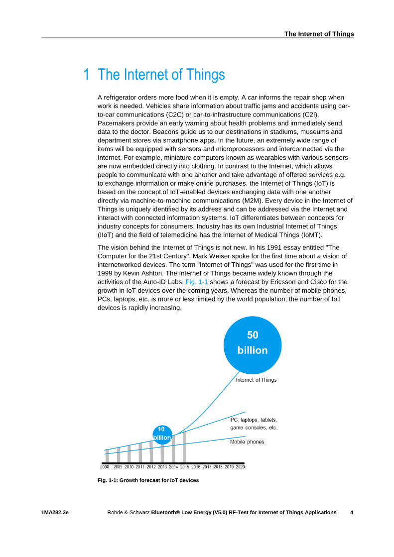
activities of the Auto-ID Labs. Fig. 1-1 shows a forecast by Ericsson and Cisco for the
growth in IoT devices over the coming years. Whereas the number of mobile phones,
PCs, laptops, etc. is more or less limited by the world population, the number of IoT
devices is rapidly increasing.
Fig. 1-1: Growth forecast for IoT devices
The Internet of Things
1MA282.3e Rohde & Schwarz Bluetooth® Low Energy (V5.0) RF-Test for Internet of Things Applications
5
The Internet of Things (IoT) is evolving in the direction of an Internet of Everything
(IoE) in which nearly everything is interconnected.
While the IoT does entail many opportunities and benefits, there are also certain
disadvantages. For example, the interconnected infrastructure could be used for
surveillance purposes or cyberattacks. There is also an increasing number of reports of
huge numbers of IoT devices being exploited to create botnets that can be externally
controlled for malicious purposes. By sending a massive number of simultaneous
requests to servers of specific Internet services, it is possible to paralyze the servers
for hours.
1.1 Connecting IoT Devices to the Internet
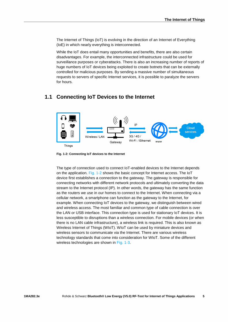
Fig. 1-2: Connecting IoT devices to the Internet
The type of connection used to connect IoT-enabled devices to the Internet depends
on the application. Fig. 1-2 shows the basic concept for Internet access. The IoT
device first establishes a connection to the gateway. The gateway is responsible for
connecting networks with different network protocols and ultimately converting the data
stream to the Internet protocol (IP). In other words, the gateway has the same function
as the routers we use in our homes to connect to the Internet. When connecting via a
cellular network, a smartphone can function as the gateway to the Internet, for
example. When connecting IoT devices to the gateway, we distinguish between wired
and wireless access. The most familiar and common type of cable connection is over
the LAN or USB interface. This connection type is used for stationary IoT devices. It is
less susceptible to disruptions than a wireless connection. For mobile devices (or when
there is no LAN cable infrastructure), a wireless link is required. This is also known as
Wireless Internet of Things (WIoT). WIoT can be used by miniature devices and
wireless sensors to communicate via the Internet. There are various wireless
technology standards that come into consideration for WIoT. Some of the different
wireless technologies are shown in Fig. 1-3.

The Internet of Things
1MA282.3e Rohde & Schwarz Bluetooth® Low Energy (V5.0) RF-Test for Internet of Things Applications
6
Fig. 1-3: Various technologies for wireless data transmission in IoT applications
Each of these technologies has advantages and disadvantages when used for IoT.
The right technology can be selected by considering the application. The various
wireless technologies differ in terms of their range, transmission speed, network
capacity, power consumption, chip size and costs. The following comparison shows
applications as well as basic differences between four wireless technology standards
selected as examples:
I Wi-Fi (specified in the IEEE 802.11 standard) for classic WLAN Internet access
Bluetooth BR/EDR (also known as "Bluetooth Classic") and Bluetooth Low Energy
(BLE) for wireless personal area networks (WPAN) to connect audio applications
as well as the data transmission of various sensors from the field of automotives,
medical technology, consumer goods and smart wearables.
I The standard IEEE 802.15.4 low-rate wireless personal networks with its various
technologies such as Zigbee, Thread, 6LoWPAN and others for sensor networks,
home automation, lighting technologyZ-Wave for home automation.
See Fig. 1-4 to Fig. 1-6 for a qualitative comparison of key parameters for these
wireless technology standards.
Fig. 1-4: Speed and power consumption for different wireless technologies
The Internet of Things
1MA282.3e Rohde & Schwarz Bluetooth® Low Energy (V5.0) RF-Test for Internet of Things Applications
7
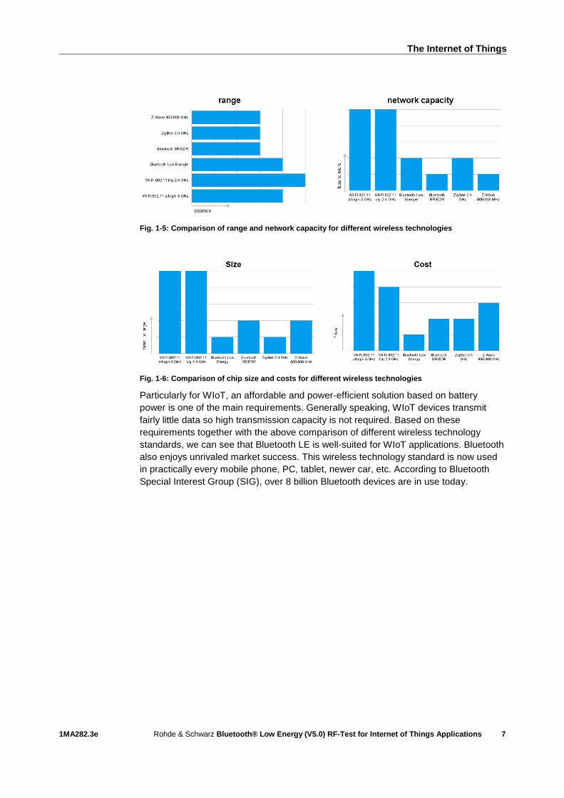
Fig. 1-5: Comparison of range and network capacity for different wireless technologies
Fig. 1-6: Comparison of chip size and costs for different wireless technologies
Particularly for WIoT, an affordable and power-efficient solution based on battery
power is one of the main requirements. Generally speaking, WIoT devices transmit
fairly little data so high transmission capacity is not required. Based on these
requirements together with the above comparison of different wireless technology
standards, we can see that Bluetooth LE is well-suited for WIoT applications. Bluetooth
also enjoys unrivaled market success. This wireless technology standard is now used
in practically every mobile phone, PC, tablet, newer car, etc. According to Bluetooth
Special Interest Group (SIG), over 8 billion Bluetooth devices are in use today.

Bluetooth Briefly Explained
1MA282.3e Rohde & Schwarz Bluetooth® Low Energy (V5.0) RF-Test for Internet of Things Applications
8
2 Bluetooth Briefly Explained
In 1989, Ericsson Mobile in Sweden began developing a wireless technology for
transmitting data between devices over short distances. This technology later became
known as Bluetooth. This technology can be used to wirelessly connect mobile phones
to a PC or headphones, for example. "Bluetooth" is an Anglicized version of the Danish
Blåtand (Old Norse Blátǫnn) in honor of the Danish King Harald Bluetooth (born
around 910 in Denmark; died November 1, 987) who united dissonant tribes in Norway
and Denmark. Just as King Bluetooth once united large parts of Denmark and Norway,
Bluetooth wireless technology brings together the computer and telecommunications
worlds and replaces a variety of different connectors. The Bluetooth logo is a
monogram combining the Old Norse runes for H and B. The wireless technology
standard was originally specified as IEEE 802.15, but it is no longer maintained. The
standard was taken over in 1998 by the new Bluetooth Special Interest Group (SIG)
originally founded by Ericsson, IBM, Intel, Nokia and Toshiba. In 1999, 3Com, Lucent,
Microsoft and Motorola joined SIG. Today, Bluetooth SIG has more than 26,000
member companies with an interest in the further development and proliferation of
Bluetooth technology. Apple, Ericsson, Lenovo, Nokia, Toshiba, Intel and Microsoft are
the Promoter member companies with a seat on the Board of Directors. Bluetooth SIG
is the owner of the Bluetooth trademark and the publisher of the Bluetooth
specification.
Only products that are licensed by SIG may use the Bluetooth trademark. To receive a
license, the company must be a member of the Bluetooth SIG. SIG also manages the
Bluetooth SIG qualification process, i.e. the certification procedure that represents
another licensing prerequisite for any product that uses Bluetooth wireless technology.
Versions
Bluetooth has gone through a number of versions over its development history. Table
2-1 shows an overview of the main versions. Officially, all versions from V2.1 (including
basic rate) are valid. Although development of the high speed mode has been
discontinued, the specification remains valid. The versions up to and including version
3 are known as Bluetooth "Classic", while the versions starting with version 4 are
called Bluetooth Low Energy (BLE). BLE is optimized for low power consumption in
battery-powered devices that require very long battery life. Bluetooth LE (starting with
V4) is not backwards-compatible. Some devices such as smartphones and tablets now
support both types of Bluetooth in "dual mode". Bluetooth Classic and Bluetooth Low
Energy are similar, but they are not compatible (Fig. 2-1).
Bluetooth Briefly Explained
1MA282.3e Rohde & Schwarz Bluetooth® Low Energy (V5.0) RF-Test for Internet of Things Applications
9
Bluetooth versions
Version Attribute Description Year Designation
1 Basic rate (BR) Conventional BT, low data rate 1999-2003
Classic
2 Enhanced data rate (EDR)
Higher transmission speed 2004-2007
3 High speed (HS) High speed mode 2009
4 Low energy (LE) Low power consumption for IoT 2010-2014 Low energy
5 Improvements for LE
Higher data rate, greater range, higher throughput
2016
Table 2-1: Overview of the main Bluetooth versions
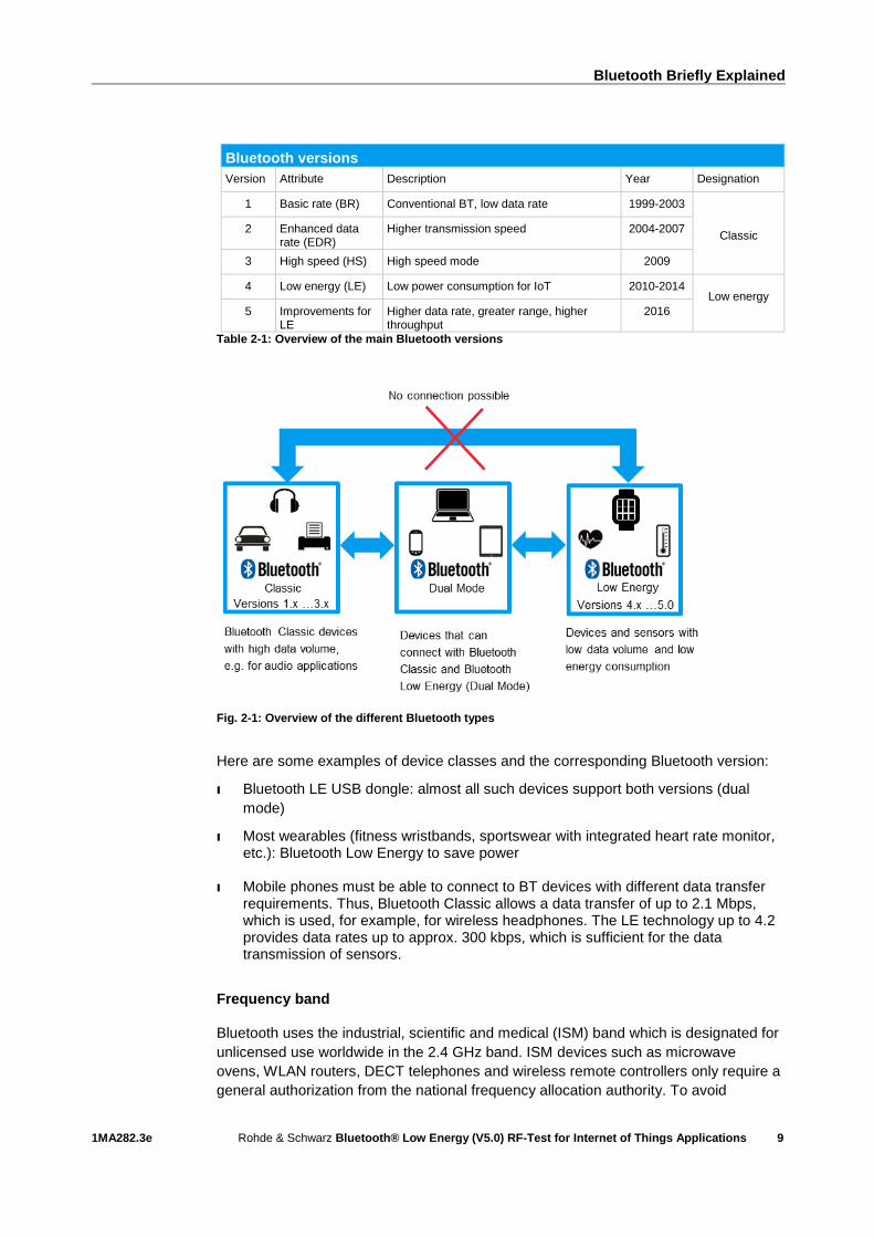
Fig. 2-1: Overview of the different Bluetooth types
Here are some examples of device classes and the corresponding Bluetooth version:
I Bluetooth LE USB dongle: almost all such devices support both versions (dual
mode)
I Most wearables (fitness wristbands, sportswear with integrated heart rate monitor, etc.): Bluetooth Low Energy to save power
I Mobile phones must be able to connect to BT devices with different data transfer requirements. Thus, Bluetooth Classic allows a data transfer of up to 2.1 Mbps, which is used, for example, for wireless headphones. The LE technology up to 4.2 provides data rates up to approx. 300 kbps, which is sufficient for the data transmission of sensors.
Frequency band Bluetooth uses the industrial, scientific and medical (ISM) band which is designated for
unlicensed use worldwide in the 2.4 GHz band. ISM devices such as microwave
ovens, WLAN routers, DECT telephones and wireless remote controllers only require a
general authorization from the national frequency allocation authority. To avoid
Bluetooth Briefly Explained
1MA282.3e Rohde & Schwarz Bluetooth® Low Energy (V5.0) RF-Test for Internet of Things Applications
10
collisions with other wireless services, Bluetooth does not use just a single frequency
channel. Data is transmitted using the frequency hopping spread spectrum (FHSS)
technique. Transmitters and receivers constantly change frequencies in an agreed
sequence. FHSS thus has low susceptibility to interference since any single carrier
frequency is only used for transmitting over a short period of time. If a frequency
happens to have interference from another transmitter, only a small part of the data
sequence will be impacted by this interference, and this can mostly be corrected (or at
least detected) using suitable error correction techniques.
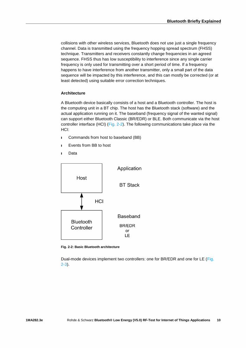
Architecture A Bluetooth device basically consists of a host and a Bluetooth controller. The host is
the computing unit in a BT chip. The host has the Bluetooth stack (software) and the
actual application running on it. The baseband (frequency signal of the wanted signal)
can support either Bluetooth Classic (BR/EDR) or BLE. Both communicate via the host
controller interface (HCI) (Fig. 2-2). The following communications take place via the
HCI:
I Commands from host to baseband (BB)
I Events from BB to host
I Data
Fig. 2-2: Basic Bluetooth architecture
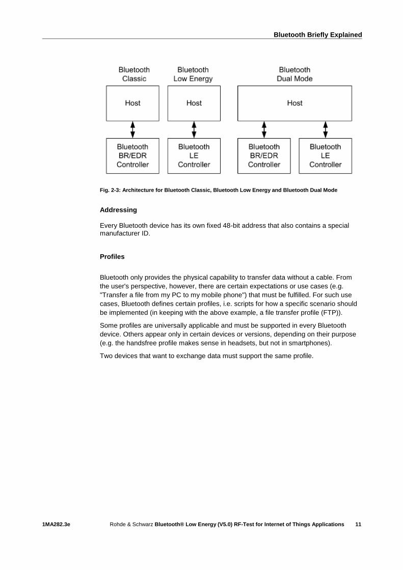
Dual-mode devices implement two controllers: one for BR/EDR and one for LE (Fig.
2-3).
Bluetooth Briefly Explained
1MA282.3e Rohde & Schwarz Bluetooth® Low Energy (V5.0) RF-Test for Internet of Things Applications
11
Fig. 2-3: Architecture for Bluetooth Classic, Bluetooth Low Energy and Bluetooth Dual Mode
Addressing Every Bluetooth device has its own fixed 48-bit address that also contains a special manufacturer ID. Profiles
Bluetooth only provides the physical capability to transfer data without a cable. From
the user's perspective, however, there are certain expectations or use cases (e.g.
"Transfer a file from my PC to my mobile phone") that must be fulfilled. For such use
cases, Bluetooth defines certain profiles, i.e. scripts for how a specific scenario should
be implemented (in keeping with the above example, a file transfer profile (FTP)).
Some profiles are universally applicable and must be supported in every Bluetooth
device. Others appear only in certain devices or versions, depending on their purpose
(e.g. the handsfree profile makes sense in headsets, but not in smartphones).
Two devices that want to exchange data must support the same profile.
Bluetooth Low Energy for IoT
1MA282.3e Rohde & Schwarz Bluetooth® Low Energy (V5.0) RF-Test for Internet of Things Applications
12
3 Bluetooth Low Energy for IoT
Bluetooth Low Energy, Bluetooth LE or simply BLE is the name for special
enhancements starting in version 4 that reduce power consumption. Versions 4.1 and
4.2 provide minor enhancements/improvements. In order to handle increasing numbers
of devices on the Internet, for example, version 4.2 added support for IPv6 (increasing
the IP address space from 4.3·109 in IP4 to 3.4·1038) to the BLE protocol stack.
Compared to Bluetooth Classic, BLE has much lower current consumption. This is
achieved by keeping a device in sleep mode most of the time (99.9 % of the time). IoT
applications require relatively low data rates. BLE also offers faster connection setup.
Version 5 introduces basic improvements such as higher data rate and greater range.
Bluetooth LE is not technically backwards-compatible. Bluetooth devices must provide
additional support for the LE protocol stack in order to connect.
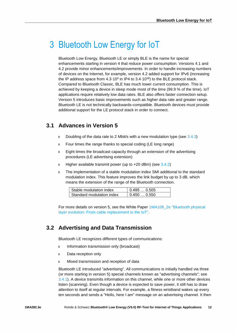
3.1 Advances in Version 5
I Doubling of the data rate to 2 Mbit/s with a new modulation type (see 3.4.3)
I Four times the range thanks to special coding (LE long range)
I Eight times the broadcast capacity through an extension of the advertising
procedures (LE advertising extension)
I Higher available transmit power (up to +20 dBm) (see 3.4.2)
I The implementation of a stable modulation index SMI additional to the standard
modulation index. This feature improves the link budget by up to 3 dB, which
means the extension of the range of the Bluetooth connection.
Stable modulation index 0.495 … 0.505
Standard modulation index 0.450 … 0.550
For more details on version 5, see the White Paper 1MA108_2e "Bluetooth physical
layer evolution: From cable replacement to the IoT".
3.2 Advertising and Data Transmission
Bluetooth LE recognizes different types of communications:
I Information transmission only (broadcast)
I Data reception only
I Mixed transmission and reception of data
Bluetooth LE introduced "advertising". All communications is initially handled via three
(or more starting in version 5) special channels known as "advertising channels"; see
3.4.1). A device transmits information on this channel, while one or more other devices
listen (scanning). Even though a device is expected to save power, it still has to draw
attention to itself at regular intervals. For example, a fitness wristband wakes up every
ten seconds and sends a "Hello, here I am" message on an advertising channel. It then

Bluetooth Low Energy for IoT
1MA282.3e Rohde & Schwarz Bluetooth® Low Energy (V5.0) RF-Test for Internet of Things Applications
13
listens briefly on the same channel to see if there is a response. If there is no
response, it tries again on the other two channels and then the processor goes back to
sleep. To save power, devices can also refrain from communicating in the scanning
process. This is implemented using a white list filter. This means the Bluetooth
controller will set up a connection with a device address only if it matches an address
stored in the white list.
Low data volumes can be exchanged directly between devices via an advertising
channel. For large volumes, an additional connection can be set up in response to a
request by a device (initiator). Both agree to meet on a channel at a certain time and
then resume frequency hopping. This corresponds to a piconet from Bluetooth Classic
with master and slave operation. The fitness wristband as a BLE device is then
connected, for example, to a smartphone and is no longer visible to other devices.
Since it can only set up one connection simultaneously, advertising no longer makes
any sense either. Simply stated, BLE devices only know three states: off, advertising
and connected.
Version 5 brought an enhancement to advertising. Data channels can now also be
used as auxiliary channels. In advertising mode, data is transmitted on the data
channels using auxiliary packets (AUX), and no true connection is set up. This is called
offloading. Offloading serves to reduce the load on the three advertising channels.
3.3 Profiles and Services
Bluetooth LE defines services and profiles. A service describes one or more features that characterize the behavior of a peripheral device. A profile describes how a service can be used for a specific application on a Gateway (smartphone or tablet). Fig. 3-1 compares services and profiles. The thermometer in this example offers
temperature measurement as a service. It transmits at a set time interval in the
advertising channel. As a dual-mode device, the tablet functions as a scanner or
initiator and uses a profile to read data from the thermometer.
Fig. 3-1: Usage of service and profile

Bluetooth Low Energy for IoT
1MA282.3e Rohde & Schwarz Bluetooth® Low Energy (V5.0) RF-Test for Internet of Things Applications
14
From the perspective of central devices (tablet , smartphone), Bluetooth LE devices always connect via the generic attribute profile (GATT). GATT is for sensor data and in general it optimizes the power-efficient transmission of low data volumes. It defines a sort of framework for profile development, i.e. profiles can derive a specific architecture from GATT. Examples of services and profiles: I BAS – battery service
I BLP – blood pressure profile
I BLP – blood pressure service
I GLP – glucose profile
I HRP – heart rate profile
I HRS – heart rate service
I LNP – location and navigation profile
I RSCP – running speed and cadence profile
I WSP – weight scale profile
3.4 Wireless Interface
3.4.1 Channels, Frequencies and Frequency Hopping
BLE uses 40 channels with a channel spacing of 2 MHz in the 2.4 GHz ISM band. This
band ranges from 2402 MHz (channel 0, logical channel 37) to 2480 MHz (channel 39,
logical channel 39). Logical channels 37, 38 and 39 are the advertising channels and
channels 0 to 36 are the data channels. The three advertising channels are arranged in
the frequency band so they cannot be disrupted by Wi-Fi channels 1, 6 and 11, which
share the ISM band (Fig. 3-2). Frequency hopping is not used until a connection has
been set up between two devices. Since advertising and data transfer in advertising do
not use frequency hopping, the European Telecommunications Standards Institute
(ETSI) does not classify Bluetooth LE as a frequency hopping system.
Fig. 3-2: Bluetooth LE channels; red: advertising channels; blue: data channels

Bluetooth Low Energy for IoT
1MA282.3e Rohde & Schwarz Bluetooth® Low Energy (V5.0) RF-Test for Internet of Things Applications
15
3.4.2 Transmit Power
The transmit power in BLE lies between –20 dBm (0.01 mW) and 20 dBm (10 mW). In
order to optimize power consumption or minimize interference for other devices,
separate power management can be implemented in a device. The following power
classes have been defined:
Class Maximum output power (dBm)
1 +20
1.5 +10
2 +4
3 0
Table 3-1: BLE power classes
3.4.3 Modulation
To keep Bluetooth LE simple, there is only one single, robust modulation mode. Like in
the Bluetooth Classic basic rate, Gaussian frequency shift keying (GFSK) is used for
modulation. The frequency deviation is ±250 kHz, allowing a gross data rate of
1 Mbit/s.
For higher data rates, version 5 introduces an optional physical layer (PHY) with twice
the frequency deviation (±500 kHz). This corresponds to a gross data rate of 2 Mbit/s.
The stable modulation index (SMI) is also optional. With SMI, devices guarantee a
modulation index between 0.495 and 0.505. This makes the frequency deviation more
precise and increases the possible range. This is possible for all PHYs.
Version 5 introduces new technologies on the lower layers. As a result, it is now
possible to define three different physical layers (PHYs). They have different frequency
deviations, coding and net data rates. The coding is used for forward error correction
and ultimately helps to increase the range up to four times. S=8 indicates that eight
symbols code one bit; correspondingly S=2 means two symbols are equal to one bit.
LE1M is mandatory and is backwards-compatible with V4.
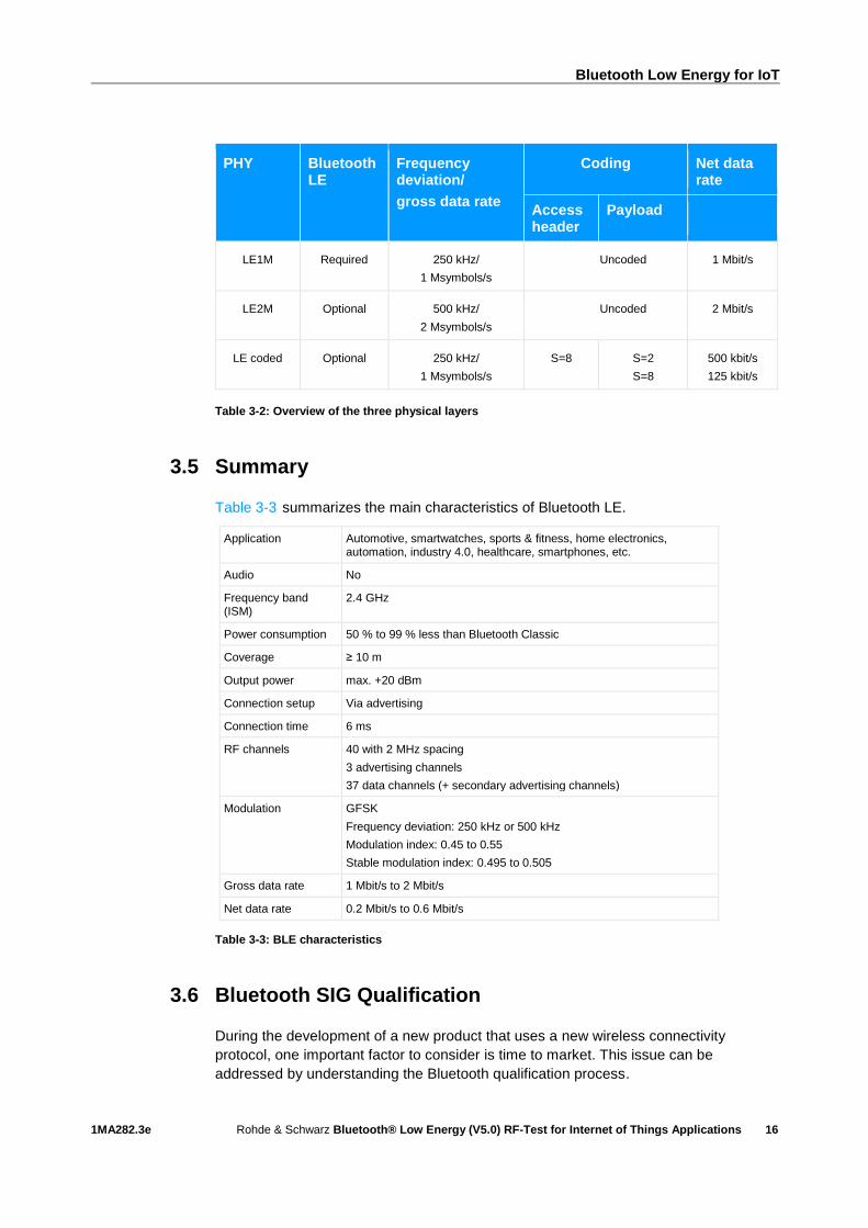
Table 3-2 shows an overview of the three PHYs.
Bluetooth Low Energy for IoT
1MA282.3e Rohde & Schwarz Bluetooth® Low Energy (V5.0) RF-Test for Internet of Things Applications
16
PHY Bluetooth LE
Frequency deviation/
gross data rate
Coding Net data rate
Access header
Payload
LE1M Required 250 kHz/
1 Msymbols/s
Uncoded 1 Mbit/s
LE2M Optional 500 kHz/
2 Msymbols/s
Uncoded 2 Mbit/s
LE coded Optional 250 kHz/
1 Msymbols/s
S=8 S=2
S=8
500 kbit/s
125 kbit/s
Table 3-2: Overview of the three physical layers
3.5 Summary
Table 3-3 summarizes the main characteristics of Bluetooth LE.
Application Automotive, smartwatches, sports & fitness, home electronics, automation, industry 4.0, healthcare, smartphones, etc.
Audio No
Frequency band (ISM)
2.4 GHz
Power consumption 50 % to 99 % less than Bluetooth Classic
Coverage ≥ 10 m
Output power max. +20 dBm
Connection setup Via advertising
Connection time 6 ms
RF channels 40 with 2 MHz spacing
3 advertising channels
37 data channels (+ secondary advertising channels)
Modulation GFSK
Frequency deviation: 250 kHz or 500 kHz
Modulation index: 0.45 to 0.55
Stable modulation index: 0.495 to 0.505
Gross data rate 1 Mbit/s to 2 Mbit/s
Net data rate 0.2 Mbit/s to 0.6 Mbit/s
Table 3-3: BLE characteristics
3.6 Bluetooth SIG Qualification
During the development of a new product that uses a new wireless connectivity
protocol, one important factor to consider is time to market. This issue can be
addressed by understanding the Bluetooth qualification process.

Bluetooth Low Energy for IoT
1MA282.3e Rohde & Schwarz Bluetooth® Low Energy (V5.0) RF-Test for Internet of Things Applications
17
How to get your Bluetooth product to market
Two main sets of approval requirements must be addressed before products using
Bluetooth technology can legally be placed on the market. The aim of the Bluetooth
qualification program defined by the Bluetooth SIG is to protect the value of Bluetooth
technology and the brand. The Bluetooth SIG compliance program is intended to
ensure that a product complies with the Bluetooth specification and will successfully
interoperate with other products that support the same Bluetooth profile. First, any
company using Bluetooth wireless technology in their products and services must
become a member of Bluetooth SIG. Depending on the developed product, the
qualification process requires different test cases, such as RF conformance testing,
protocol and profile conformance testing and profile interoperability testing. After a
product “passes” all required test cases and its compliance is declared, companies are
able to sell and brand their products with Bluetooth trademarks. National type approval
requirements also apply to Bluetooth products and are a primary requirement for
market entry. In general, three product certification requirements apply to Bluetooth
products:
The radio type approval or RF transmitter/transceiver unit
The EMC certification of the RF part, usually when installed within the host unit
and relative to normal configuration and conditions of usage
Safety certification, usually dependent upon the operating voltage of the
product and any associated power supplies
If RF conformance testing and national radio type approval is needed, testing is
generally required at a test laboratory accredited by the Bluetooth SIG and by the
country of interest. In order to be sure that the product will pass the conformance test,
it would make sense to perform an in-house preconformance test. Any problems can
be detected and corrected quickly before the conformance test. This will save time and
money on the way to launching a new product. In the following, RF PHY pre-
conformance testing will be described.
Fig. 3-3: Bluetooth qualification process

RF Measurements on a Bluetooth LE Device in Accordance with the Specification
1MA282.3e Rohde & Schwarz Bluetooth® Low Energy (V5.0) RF-Test for Internet of Things Applications
18
4 RF Measurements on a Bluetooth LE
Device in Accordance with the Specification
The Bluetooth Special Interest Group (SIG) defines the measurements to be performed
on the radio interface as part of the qualification process. All Bluetooth devices must
prove they satisfy the specification requirements in a Bluetooth qualification and test
facility (BQTF). For Bluetooth Low Energy devices, the test specification that is
relevant is the Bluetooth test specification: (RF) // RF-PHY.TS.5.0.0 [3].
A distinction is made between transmitter (TX) and receiver (RX) tests. Since various
chips with various applications exist in Bluetooth only a subset of the tests may be
relevant in some cases. Beacons for example transmit only, but cannot receive.
The test specification [3] defines some fundamental tests that must be performed
depending on the PHY.
RF transmitter measurements
ı Output power
ı In-band emissions
ı Modulation characteristics
ı Carrier frequency offset and drift
RF receiver tests
ı Receiver sensitivity
ı C/I and receiver selectivity performance
ı Blocking performance
ı Intermodulation performance
ı Maximum input signal level
ı PER report integrity
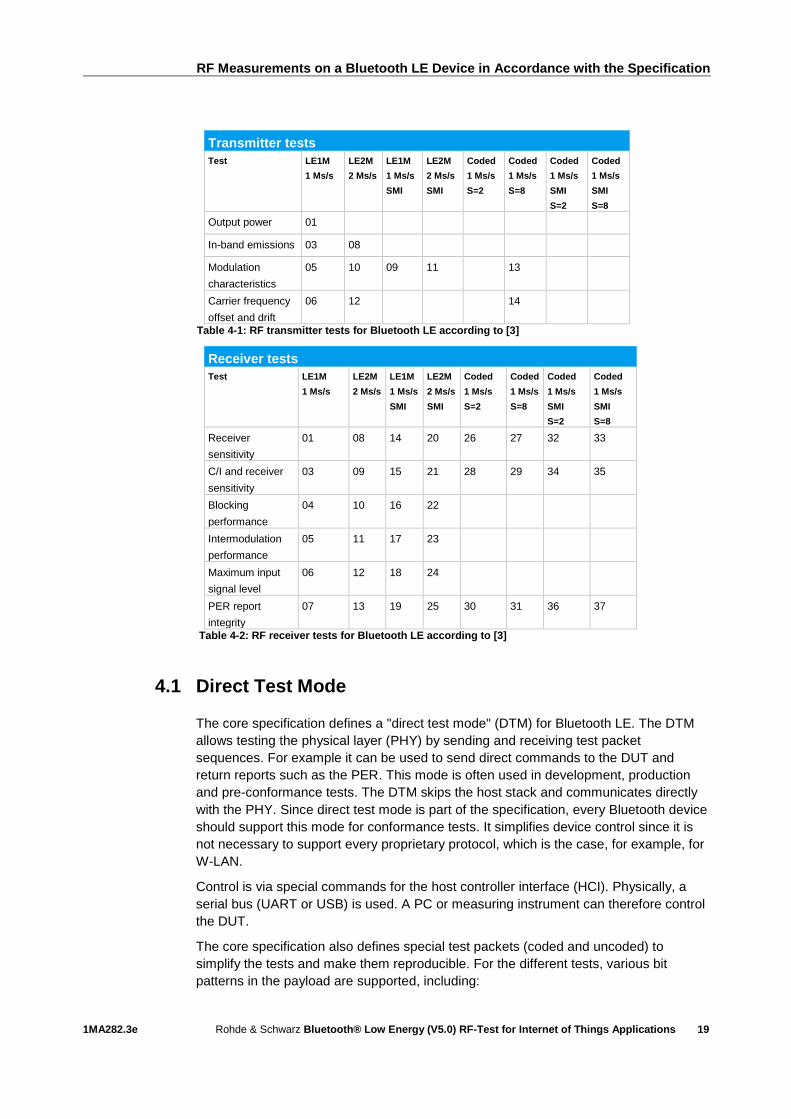
These fundamental tests are repeated for the various PHYs. Table 4-1 and Table 4-2
provide an overview. The transmitter tests are designated as TP/TRM-LE/CA/BV-xx-C
and the receiver tests as TP/RCV-LE/CA/BV-xx-C. The corresponding numerals in the
different tables must be inserted. All tests listed below are nonhopping and must be
performed on single RF channels. SMI is the abbreviation for stable modulation index.
RF Measurements on a Bluetooth LE Device in Accordance with the Specification
1MA282.3e Rohde & Schwarz Bluetooth® Low Energy (V5.0) RF-Test for Internet of Things Applications
19
Transmitter tests
Test LE1M
1 Ms/s
LE2M
2 Ms/s
LE1M
1 Ms/s
SMI
LE2M
2 Ms/s
SMI
Coded
1 Ms/s
S=2
Coded
1 Ms/s
S=8
Coded
1 Ms/s
SMI
S=2
Coded
1 Ms/s
SMI
S=8
Output power 01
In-band emissions 03 08
Modulation
characteristics
05 10 09 11 13
Carrier frequency
offset and drift
06 12 14
Table 4-1: RF transmitter tests for Bluetooth LE according to [3]
Receiver tests
Test LE1M
1 Ms/s
LE2M
2 Ms/s
LE1M
1 Ms/s
SMI
LE2M
2 Ms/s
SMI
Coded
1 Ms/s
S=2
Coded
1 Ms/s
S=8
Coded
1 Ms/s
SMI
S=2
Coded
1 Ms/s
SMI
S=8
Receiver
sensitivity
01 08 14 20 26 27 32 33
C/I and receiver
sensitivity
03 09 15 21 28 29 34 35
Blocking
performance
04 10 16 22
Intermodulation
performance
05 11 17 23
Maximum input
signal level
06 12 18 24
PER report
integrity
07 13 19 25 30 31 36 37
Table 4-2: RF receiver tests for Bluetooth LE according to [3]
4.1 Direct Test Mode
The core specification defines a "direct test mode" (DTM) for Bluetooth LE. The DTM
allows testing the physical layer (PHY) by sending and receiving test packet
sequences. For example it can be used to send direct commands to the DUT and
return reports such as the PER. This mode is often used in development, production
and pre-conformance tests. The DTM skips the host stack and communicates directly
with the PHY. Since direct test mode is part of the specification, every Bluetooth device
should support this mode for conformance tests. It simplifies device control since it is
not necessary to support every proprietary protocol, which is the case, for example, for
W-LAN.
Control is via special commands for the host controller interface (HCI). Physically, a
serial bus (UART or USB) is used. A PC or measuring instrument can therefore control
the DUT.
The core specification also defines special test packets (coded and uncoded) to
simplify the tests and make them reproducible. For the different tests, various bit
patterns in the payload are supported, including:
RF Measurements on a Bluetooth LE Device in Accordance with the Specification
1MA282.3e Rohde & Schwarz Bluetooth® Low Energy (V5.0) RF-Test for Internet of Things Applications
20
ı Pseudorandom bit pattern with a length of 29 –1 (PRBS9) or 215 –1 (PRBS15)
ı Alternating bit sequence: 01010101…
ı All zeros or ones: 00000000 or 11111111
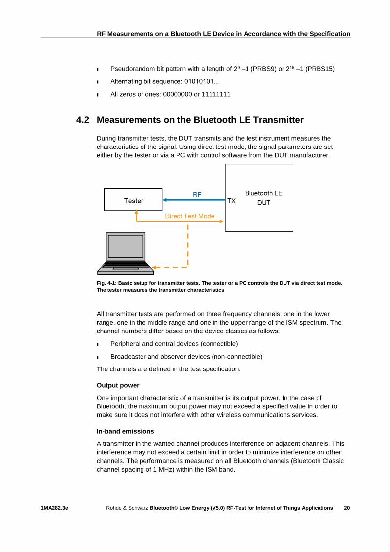
4.2 Measurements on the Bluetooth LE Transmitter
During transmitter tests, the DUT transmits and the test instrument measures the
characteristics of the signal. Using direct test mode, the signal parameters are set
either by the tester or via a PC with control software from the DUT manufacturer.
Fig. 4-1: Basic setup for transmitter tests. The tester or a PC controls the DUT via direct test mode.
The tester measures the transmitter characteristics
All transmitter tests are performed on three frequency channels: one in the lower
range, one in the middle range and one in the upper range of the ISM spectrum. The
channel numbers differ based on the device classes as follows:
ı Peripheral and central devices (connectible)
ı Broadcaster and observer devices (non-connectible)
The channels are defined in the test specification.
Output power
One important characteristic of a transmitter is its output power. In the case of
Bluetooth, the maximum output power may not exceed a specified value in order to
make sure it does not interfere with other wireless communications services.
In-band emissions
A transmitter in the wanted channel produces interference on adjacent channels. This
interference may not exceed a certain limit in order to minimize interference on other
channels. The performance is measured on all Bluetooth channels (Bluetooth Classic
channel spacing of 1 MHz) within the ISM band.
RF Measurements on a Bluetooth LE Device in Accordance with the Specification
1MA282.3e Rohde & Schwarz Bluetooth® Low Energy (V5.0) RF-Test for Internet of Things Applications
21
Modulation characteristics
The signal quality is important in order for the transmitter and receiver to understand
each other. This test measures the signal quality based on the modulation.
Carrier frequency offset and drift
This test also measures the signal quality. The transmitter and receiver must operate
on the same frequency. This test measures the difference between the transmitter
frequency and the nominal frequency as well as the additional deviation of the center
frequency during transmission of a complete packet.
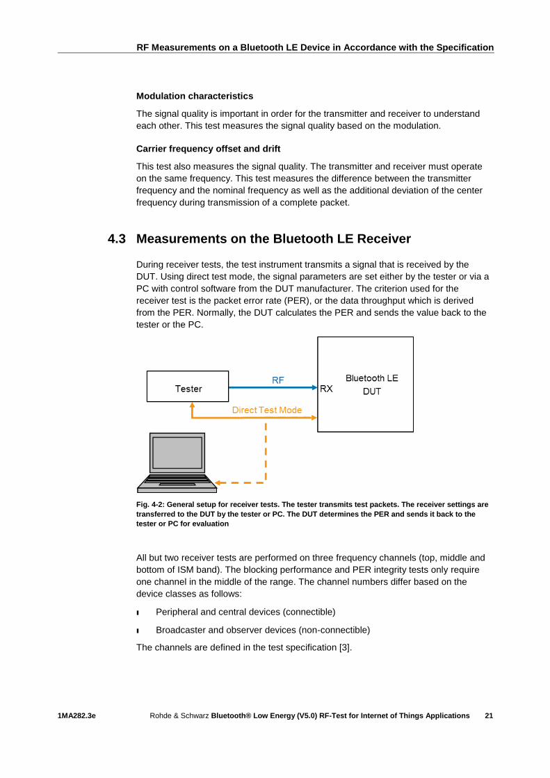
4.3 Measurements on the Bluetooth LE Receiver
During receiver tests, the test instrument transmits a signal that is received by the
DUT. Using direct test mode, the signal parameters are set either by the tester or via a
PC with control software from the DUT manufacturer. The criterion used for the
receiver test is the packet error rate (PER), or the data throughput which is derived
from the PER. Normally, the DUT calculates the PER and sends the value back to the
tester or the PC.
Fig. 4-2: General setup for receiver tests. The tester transmits test packets. The receiver settings are
transferred to the DUT by the tester or PC. The DUT determines the PER and sends it back to the
tester or PC for evaluation
All but two receiver tests are performed on three frequency channels (top, middle and
bottom of ISM band). The blocking performance and PER integrity tests only require
one channel in the middle of the range. The channel numbers differ based on the
device classes as follows:
ı Peripheral and central devices (connectible)
ı Broadcaster and observer devices (non-connectible)
The channels are defined in the test specification [3].
RF Measurements on a Bluetooth LE Device in Accordance with the Specification
1MA282.3e Rohde & Schwarz Bluetooth® Low Energy (V5.0) RF-Test for Internet of Things Applications
22
Receiver sensitivity
The most important characteristic of the receiver is its sensitivity, i.e. just how weak a
signal can the receiver successfully understand. In Bluetooth tests, a malfunctioning
("dirty") transmitter is also simulated.
C/I and receiver selectivity performance
In the ISM band, multiple Bluetooth transmissions can take place simultaneously
between different devices. Different channels are used for this purpose. In this test, the
receiver performance is measured in the presence of interference from other Bluetooth
LE transmissions in adjacent channels.
Blocking performance
Various wireless systems such as mobile communications networks, satellite
communications systems, satellite-based and radar-based navigation systems also
transmit signals outside the ISM band. In this test, the receiver performance is checked
in the presence of interference from other wireless transmissions outside the ISM
band.
Intermodulation performance
Due to nonlinearities, two or more transmitters can produce new, additional interferers
on specific frequencies. In this test, the receiver performance is measured in the
presence of interference due to intermodulation.
Maximum input signal level
How the receiver behaves in response to weak signals is tested under receiver
sensitivity. In Bluetooth, relatively strong signals can occur due to the spatial proximity
of the devices. This test tests the receiver performance in the presence of strong
signals.
PER report integrity
This is actually not an RF test. Instead, the error correction software in the receiver is
tested. The receiver has to properly handle packets with predefined errors that are
artificially inserted.
Measurements with the CMW
1MA282.3e Rohde & Schwarz Bluetooth® Low Energy (V5.0) RF-Test for Internet of Things Applications
23
5 Measurements with the CMW
The CMW family is the ideal platform for Bluetooth tests. It can perform all Bluetooth
tests in line with the specification. This includes tests in development and production
as well as precompliance tests (additional T&M instruments required for precompliance
tests). It is also easy to perform co-existence tests with other wireless technology
standards. The following test instruments in the CMW platform support Bluetooth:
ı CMW500 - Flexible radio communication tester with all conventional wireless
technology standards
ı CMW270 - Wireless connectivity tester
ı CMW290 - IoT tester
ı CMW100 - Production solution (non-signaling)
The CMW500, 270 und 290 support the direct test mode defined in the Bluetooth
specification [4]. The Direct Test Mode provides a selection of different RF test for
Bluetooth Low Energy Devices including the Remote Control Commandos for the USB
or R232 interface. All Bluetooth test cases can be covered with the the obove
mentioned CMW models (see Table 5-1).

Measurements with the CMW
1MA282.3e Rohde & Schwarz Bluetooth® Low Energy (V5.0) RF-Test for Internet of Things Applications
24
Table 5-1: All Bluetooth LE HF-test cases are supported by the MW500, 270 und 290
Test setup
Most of the tests (e.g. for development and production) can be performed with the
CMW alone with the following test setup:
Fig. 5-1: The test setup with the CMW covers most transmitter and receiver tests. It also supports the
direct test mode via USB

Measurements with the CMW
1MA282.3e Rohde & Schwarz Bluetooth® Low Energy (V5.0) RF-Test for Internet of Things Applications
25
For all tests (preconformance), an additional signal generator is required:
Fig. 5-2: This test setup with the CMW and an additional signal generator can be used to perform all
transmitter and receiver tests in line with the specification. A filter suppresses any interference that
might be produced by the CW generator in the Bluetooth band
5.1 Tests in Manual Operation
5.1.1 Initial Steps
For the Bluetooth tests, the following applications are required in the CMW firmware:
ı Bluetooth Signaling
ı Bluetooth Multi Evaluation
ı Bluetooth RX Measurement
1. Use the SIGNAL GEN or MEASURE hardkeys to select the required applications.
Go to the signaling application, e.g. by pressing TASKS.
2. Go to Bluetooth Signaling.

Measurements with the CMW
1MA282.3e Rohde & Schwarz Bluetooth® Low Energy (V5.0) RF-Test for Internet of Things Applications
26
Fig. 5-3: The Bluetooth Signaling start screen. IoT tests run under Low Energy
3. IoT Bluetooth uses the Low Energy variant. Select Low Energy under Burst Type.
4. The CMW supports all three PHYs for Bluetooth version 5:
The three PHYs in the CMW
LE1M 1 Mbps
LE2M 2 Mbps
LE coded Long range
Table 5-2: Three PHYs in the CMW. Long Range supports coding schemes S=2 and S=8
5. On the left, select the type of connection to the DUT (EUT Control, HW
Interface). Direct test mode is then automatically activated. Switch on the
signaling. See application note 1C105 [xx] for more information on this topic.
6. The screen should now look like Fig. 5-4.
7. Click Connection Check at any time to verify the HCI connection to the DUT in
direct test mode.

Measurements with the CMW
1MA282.3e Rohde & Schwarz Bluetooth® Low Energy (V5.0) RF-Test for Internet of Things Applications
27
Fig. 5-4: Low energy and direct test mode are activated
Fig. 5-5: Long range supports both coding schemes
Fig. 5-6: Verification of the connection to the DUT in direct test mode
8. Click Bluetooth Multi Eval. (top right) to switch to the TX measurement screen.
Activate the measurements by selecting Multi Evaluation (top right) and ON.
Measurements with the CMW
1MA282.3e Rohde & Schwarz Bluetooth® Low Energy (V5.0) RF-Test for Internet of Things Applications
28
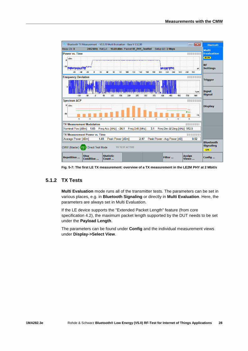
Fig. 5-7: The first LE TX measurement: overview of a TX measurement in the LE2M PHY at 2 Mbit/s
5.1.2 TX Tests
Multi Evaluation mode runs all of the transmitter tests. The parameters can be set in
various places, e.g. in Bluetooth Signaling or directly in Multi Evaluation. Here, the
parameters are always set in Multi Evaluation.
If the LE device supports the "Extended Packet Length" feature (from core
specification 4.2), the maximum packet length supported by the DUT needs to be set
under the Payload Length.
The parameters can be found under Config and the individual measurement views
under Display->Select View.
Measurements with the CMW
1MA282.3e Rohde & Schwarz Bluetooth® Low Energy (V5.0) RF-Test for Internet of Things Applications
29
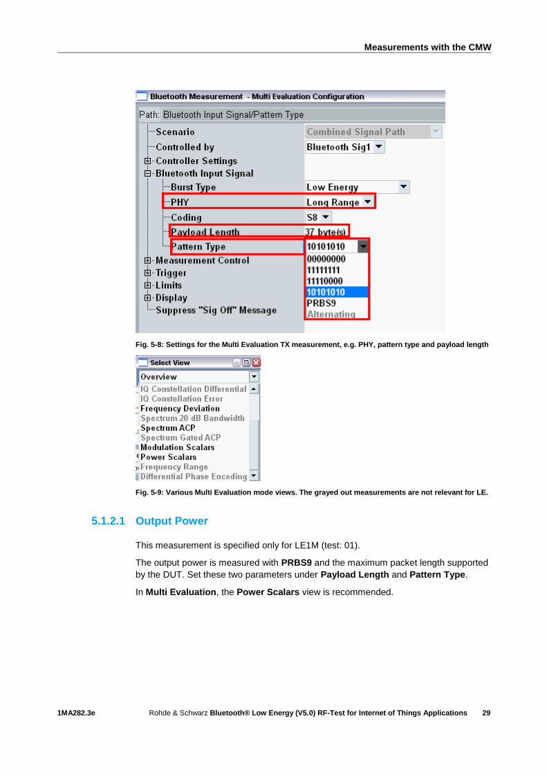
Fig. 5-8: Settings for the Multi Evaluation TX measurement, e.g. PHY, pattern type and payload length
Fig. 5-9: Various Multi Evaluation mode views. The grayed out measurements are not relevant for LE.
5.1.2.1 Output Power
This measurement is specified only for LE1M (test: 01).
The output power is measured with PRBS9 and the maximum packet length supported
by the DUT. Set these two parameters under Payload Length and Pattern Type.
In Multi Evaluation, the Power Scalars view is recommended.
Measurements with the CMW
1MA282.3e Rohde & Schwarz Bluetooth® Low Energy (V5.0) RF-Test for Internet of Things Applications
30
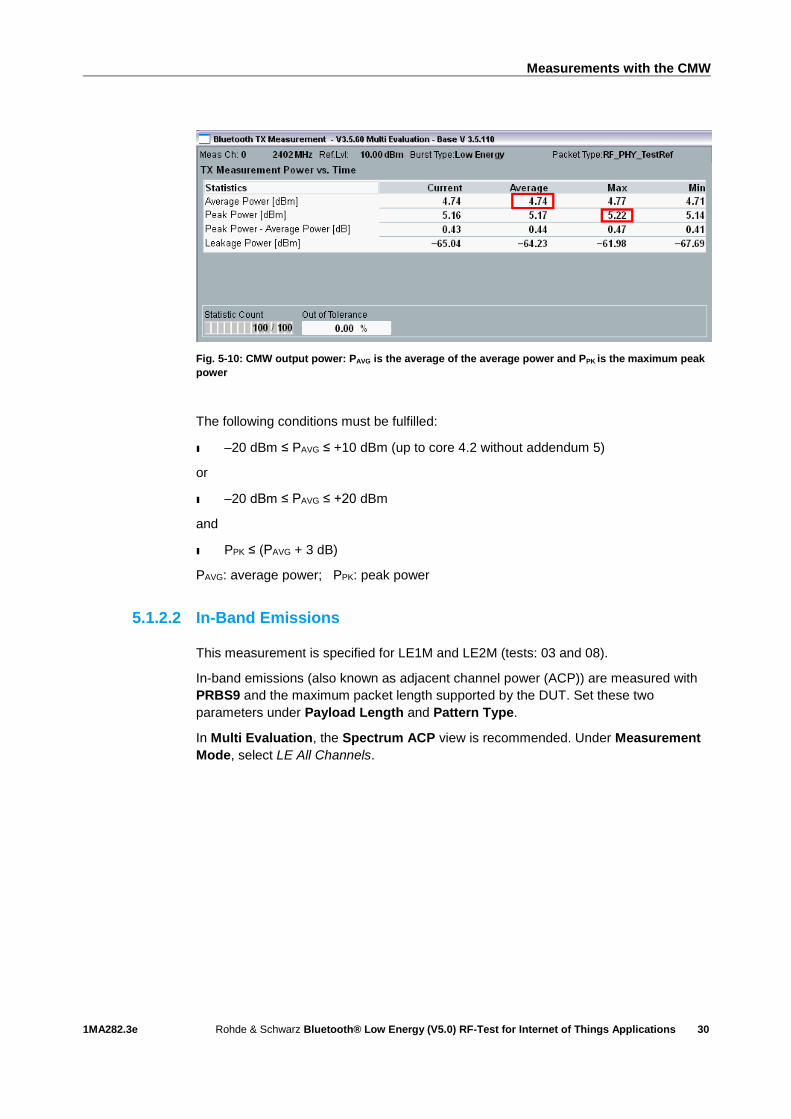
Fig. 5-10: CMW output power: PAVG is the average of the average power and PPK is the maximum peak
power
The following conditions must be fulfilled:
ı –20 dBm ≤ PAVG ≤ +10 dBm (up to core 4.2 without addendum 5)
or
ı –20 dBm ≤ PAVG ≤ +20 dBm
and
ı PPK ≤ (PAVG + 3 dB)
PAVG: average power; PPK: peak power
5.1.2.2 In-Band Emissions
This measurement is specified for LE1M and LE2M (tests: 03 and 08).
In-band emissions (also known as adjacent channel power (ACP)) are measured with
PRBS9 and the maximum packet length supported by the DUT. Set these two
parameters under Payload Length and Pattern Type.
In Multi Evaluation, the Spectrum ACP view is recommended. Under Measurement
Mode, select LE All Channels.
Measurements with the CMW
1MA282.3e Rohde & Schwarz Bluetooth® Low Energy (V5.0) RF-Test for Internet of Things Applications
31
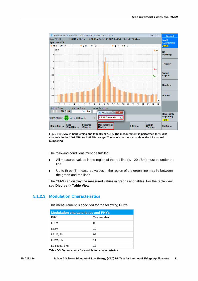
Fig. 5-11: CMW in-band emissions (spectrum ACP). The measurement is performed for 1 MHz
channels in the 2401 MHz to 2481 MHz range. The labels on the x axis show the LE channel
numbering
The following conditions must be fulfilled:
ı All measured values in the region of the red line ( ≤ –20 dBm) must be under the
line
ı Up to three (3) measured values in the region of the green line may lie between
the green and red lines
The CMW can display the measured values in graphs and tables. For the table view,
see Display -> Table View.
5.1.2.3 Modulation Characteristics
This measurement is specified for the following PHYs:
Modulation characteristics and PHYs
PHY Test number
LE1M 05
LE2M 10
LE1M, SMI 09
LE2M, SMI 11
LE coded, S=8 13
Table 5-3: Various tests for modulation characteristics
Measurements with the CMW
1MA282.3e Rohde & Schwarz Bluetooth® Low Energy (V5.0) RF-Test for Internet of Things Applications
32
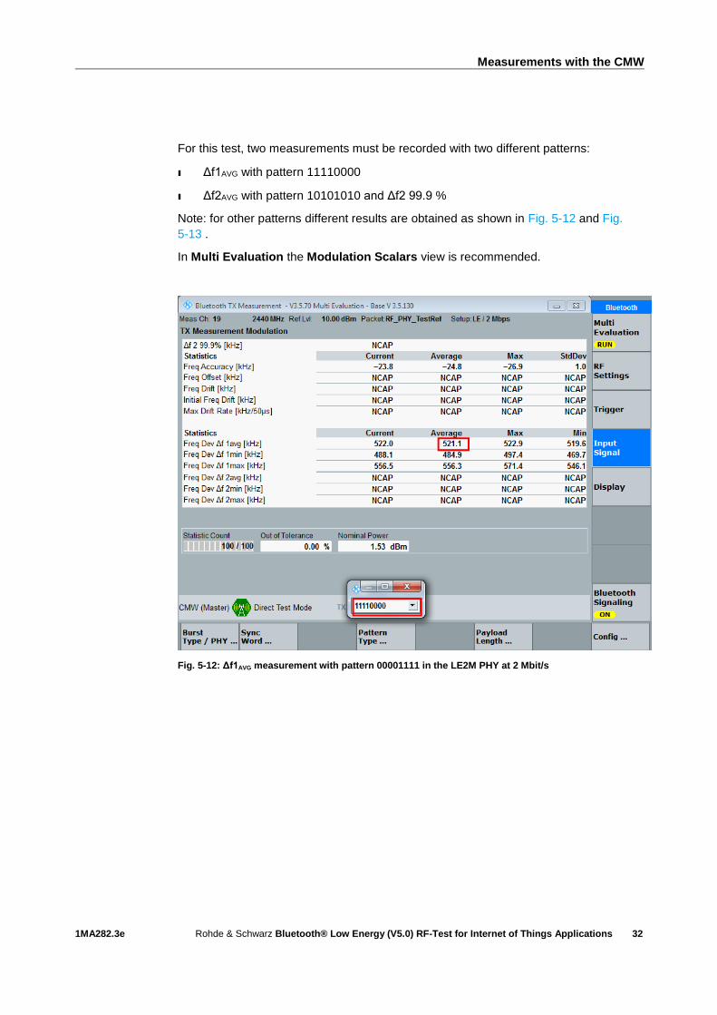
For this test, two measurements must be recorded with two different patterns:
ı Δf1AVG with pattern 11110000
ı Δf2AVG with pattern 10101010 and Δf2 99.9 %
Note: for other patterns different results are obtained as shown in Fig. 5-12 and Fig.
5-13 .
In Multi Evaluation the Modulation Scalars view is recommended.
Fig. 5-12: Δf1AVG measurement with pattern 00001111 in the LE2M PHY at 2 Mbit/s

Measurements with the CMW
1MA282.3e Rohde & Schwarz Bluetooth® Low Energy (V5.0) RF-Test for Internet of Things Applications
33
Fig. 5-13: Δf2AVG measurement with pattern 01010101 and Δf2 99.9 % measurement in the LE2M PHY
at 2 Mbit/s
The following conditions must be fulfilled:
Modulation characteristics
Measured value
LE1M
Test 05
LE2M
Test 10
LE1M with SMI
Test 09
LE2M with SMI
Test 11
LE coded S=8
Test 13
Δf1AVG 225 kHz ≤
x
≤ 275 kHz
450 kHz ≤
x
≤ 550 kHz
247.5 kHz ≤
x
≤ 252.5 kHz
495 kHz ≤
x
≤ 505 kHz
225 kHz ≤
x
≤ 275 kHz
Δf2 99.9 %
> 185 kHz > 370 kHz > 185 kHz > 370 kHz > 185 kHz
Δf2AVG
Δf1AVG
≥ 0.8 ≥ 0.8 ≥ 0.8 ≥ 0.8 ?
Table 5-4: Limits for modulation characteristics
5.1.2.4 Carrier Frequency Offset and Drift
This measurement is specified for the following PHYs:

Measurements with the CMW
1MA282.3e Rohde & Schwarz Bluetooth® Low Energy (V5.0) RF-Test for Internet of Things Applications
34
Frequency offset and drift and PHYs
PHY Test number
LE1M 06
LE2M 12
LE coded, S=8 14
Table 5-5: Various tests for frequency offset and drift
The output power is measured with 10101010 and the maximum packet length
supported by the DUT. Set these two parameters under Payload Length and Pattern
Type.
In Multi Evaluation the Modulation Scalars view is recommended.
Fig. 5-14: Measured values for carrier frequency offset and drift. The measured values according to
the specification are always the maximum values
The following conditions must be fulfilled:
Frequency offset and drift
Measured value LE1M
Test 06
LE2M
Test 12
LE coded with S=8
Test 14
Freq. offset ≤ 150 kHz ≤ 150 kHz ≤ 150 kHz
Freq. drift ≤ 50 kHz ≤ 50 kHz ≤ 50 kHz
Initial freq. drift ≤ 23 kHz ≤ 23 kHz ≤ 19.2 kHz
Max. drift rate ≤ 20 kHz ≤ 20 kHz ≤ 19.2 kHz
Table 5-6: Frequency offset and drift limits
Measurements with the CMW
1MA282.3e Rohde & Schwarz Bluetooth® Low Energy (V5.0) RF-Test for Internet of Things Applications
35
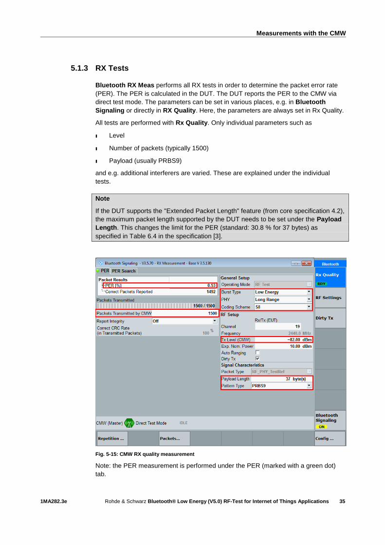
5.1.3 RX Tests
Bluetooth RX Meas performs all RX tests in order to determine the packet error rate
(PER). The PER is calculated in the DUT. The DUT reports the PER to the CMW via
direct test mode. The parameters can be set in various places, e.g. in Bluetooth
Signaling or directly in RX Quality. Here, the parameters are always set in Rx Quality.
All tests are performed with Rx Quality. Only individual parameters such as
ı Level
ı Number of packets (typically 1500)
ı Payload (usually PRBS9)
and e.g. additional interferers are varied. These are explained under the individual
tests.
Note
If the DUT supports the "Extended Packet Length" feature (from core specification 4.2),
the maximum packet length supported by the DUT needs to be set under the Payload
Length. This changes the limit for the PER (standard: 30.8 % for 37 bytes) as
specified in Table 6.4 in the specification [3].
Fig. 5-15: CMW RX quality measurement
Note: the PER measurement is performed under the PER (marked with a green dot)
tab.

Measurements with the CMW
1MA282.3e Rohde & Schwarz Bluetooth® Low Energy (V5.0) RF-Test for Internet of Things Applications
36
5.1.3.1 Receiver Sensitivity
This test is specified for all PHYs:
Receiver sensitivity and PHYs
PHY Test number Reference level
LE1M 01 –70 dBm
LE2M 08
LE1M, SMI 14
LE2M, SMI 20
LE coded, S=2 26 –75 dBm
LE coded, S=8 27 –82 dBm
LE coded, S=2, SMI 32 –75 dBm
LE coded, S=8, SMI 33 –82 dBm
Table 5-7: Various tests for receiver sensitivity
First select the wanted PHY. For this test, set PRBS9, 1500 packets and a level as
specified in Table 5-7. In addition, a non-optimal transmitter ("Dirty Tx") is simulated. At
the top right, click Dirty Tx and make sure that Dirty Tx Mode is set to Spec Table
(bottom). Set Dirty Tx to On (bottom) and restart the measurement (Rx Quality:
Restart). All parameters are now set in compliance with the specification. If necessary,
set the SMI under CONFIG|DIRTY TX:
Fig. 5-16: SMI is located under Rx Qual CONFIG

Measurements with the CMW
1MA282.3e Rohde & Schwarz Bluetooth® Low Energy (V5.0) RF-Test for Internet of Things Applications
37
Fig. 5-17: CMW Dirty Tx
The following conditions must be fulfilled:
ı PER < 30.8 %
5.1.3.2 C/I and Receiver Selectivity Performance
This test is specified for all PHYs:
C/I and receiver selectivity and PHYs
PHY Test number
LE1M 03
LE2M 09
LE1M, SMI 15
LE2M, SMI 21
LE coded, S=2 28
LE coded, S=8 29
LE coded, S=2, SMI 34
LE coded, S=8, SMI 35
Table 5-8: Various tests for C/I and receiver selectivity
This test tests the behavior of the receiver under the influence of a second Bluetooth
signal. A Bluetooth interferer is set with certain levels and frequency spacing from the
Measurements with the CMW
1MA282.3e Rohde & Schwarz Bluetooth® Low Energy (V5.0) RF-Test for Internet of Things Applications
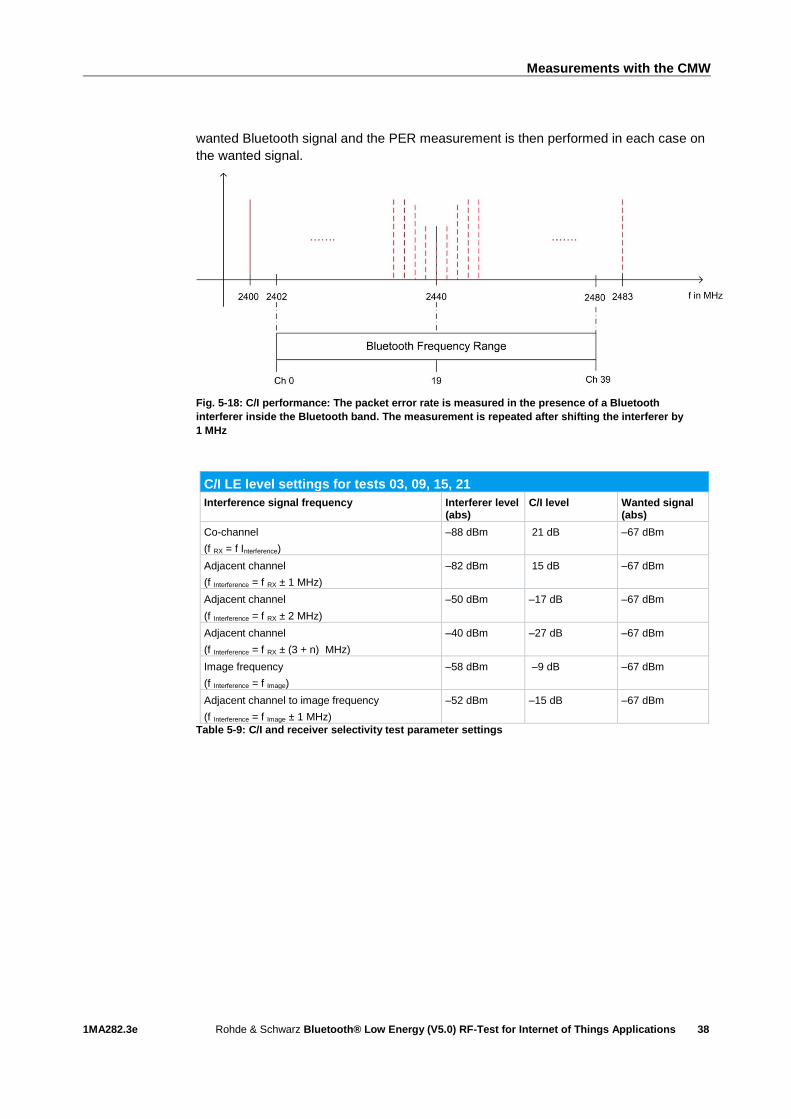
38
wanted Bluetooth signal and the PER measurement is then performed in each case on
the wanted signal.
Fig. 5-18: C/I performance: The packet error rate is measured in the presence of a Bluetooth
interferer inside the Bluetooth band. The measurement is repeated after shifting the interferer by
1 MHz
C/I LE level settings for tests 03, 09, 15, 21
Interference signal frequency Interferer level (abs)
C/I level Wanted signal (abs)
Co-channel
(f RX = f Interference)
–88 dBm 21 dB –67 dBm
Adjacent channel
(f Interference = f RX ± 1 MHz)
–82 dBm 15 dB –67 dBm
Adjacent channel
(f Interference = f RX ± 2 MHz)
–50 dBm –17 dB –67 dBm
Adjacent channel
(f Interference = f RX ± (3 + n) MHz)
–40 dBm –27 dB –67 dBm
Image frequency
(f Interference = f Image)
–58 dBm –9 dB –67 dBm
Adjacent channel to image frequency
(f Interference = f Image ± 1 MHz)
–52 dBm –15 dB –67 dBm
Table 5-9: C/I and receiver selectivity test parameter settings

Measurements with the CMW
1MA282.3e Rohde & Schwarz Bluetooth® Low Energy (V5.0) RF-Test for Internet of Things Applications
39
C/I LE level settings for tests 28, 34
Interference signal frequency Interferer level (abs)
C/I level Wanted signal (abs)
Co-channel
(f RX = f Interference)
–89 dBm 17 dB –72 dBm
Adjacent channel
(f Interference = f RX ± 1 MHz)
–83 dBm 11 dB –72 dBm
Adjacent channel
(f Interference = f RX ± 2 MHz)
–51 dBm –21 dB –72 dBm
Adjacent channel
(f Interference = f RX ± (3 + n) MHz)
–41 dBm –31 dB –72 dBm
Image frequency
(f Interference = f Image)
–59 dBm –13 dB –72 dBm
Adjacent channel to image frequency
(f Interference = f Image ± 1 MHz)
–53 dBm –19 dB –72 dBm
Table 5-10: C/I and receiver selectivity test parameter settings for LE coded with S=2
C/I LE level settings for tests 29, 35
Interference signal frequency Interferer level (abs)
C/I level Wanted signal (abs)
Co-channel
(f RX = f Interference)
–91 dBm 12 dB –79 dBm
Adjacent channel
(f Interference = f RX ± 1 MHz)
–85 dBm 6 dB –79 dBm
Adjacent channel
(f Interference = f RX ± 2 MHz)
–53 dBm –26 dB –79 dBm
Adjacent channel
(f Interference = f RX ± (3 + n) MHz)
–43 dBm –36 dB –79 dBm
Image frequency
(f Interference = f Image)
–61 dBm –18 dB –79 dBm
Adjacent channel to image frequency
(f Interference = f Image ± 1 MHz)
–55 dBm –24 dB –79 dBm
Table 5-11: C/I and receiver selectivity test parameter settings for LE coded with S=8
Settings:
ı Signal with PRBS9 and level depending on PHY: –67 dBm, –72 dBm or –79 dBm
ı 1500 packets
Continuous interferer with GFSK with PRBS15 depending on PHY, level depending on
frequency spacing (Table 5-9, Table 5-10 or Table 5-11). 2400 MHz start frequency, up
to 2483 MHz in 1 MHz steps.
The Bluetooth interferer can be produced with an additional generator such as the
SMBV or SMW. Here, we describe a solution with the general purpose RF generator
(GPRF) in the CMW. Select ARB as the baseband mode in the GPRF and load the
provided PHY-specific file.
ı GFSK_PRBS15_MOD0p50.wv for LE1M
ı LE2M_INTERFERER_PRBS15.wv for LE2M
ı BTLELR_INTEFERENCE_FEC2_PRBS15.wv for LE coded with S=2
Measurements with the CMW
1MA282.3e Rohde & Schwarz Bluetooth® Low Energy (V5.0) RF-Test for Internet of Things Applications
40
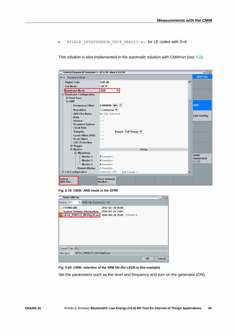
ı BTLELR_INTEFERENCE_FEC8_PRBS15.wv for LE coded with S=8
This solution is also implemented in the automatic solution with CMWrun (see 5.2).
Fig. 5-19: CMW: ARB mode in the GPRF
Fig. 5-20: CMW: selection of the ARB file (for LE1M in this example)
Set the parameters such as the level and frequency and turn on the generator (ON).
Measurements with the CMW
1MA282.3e Rohde & Schwarz Bluetooth® Low Energy (V5.0) RF-Test for Internet of Things Applications
41
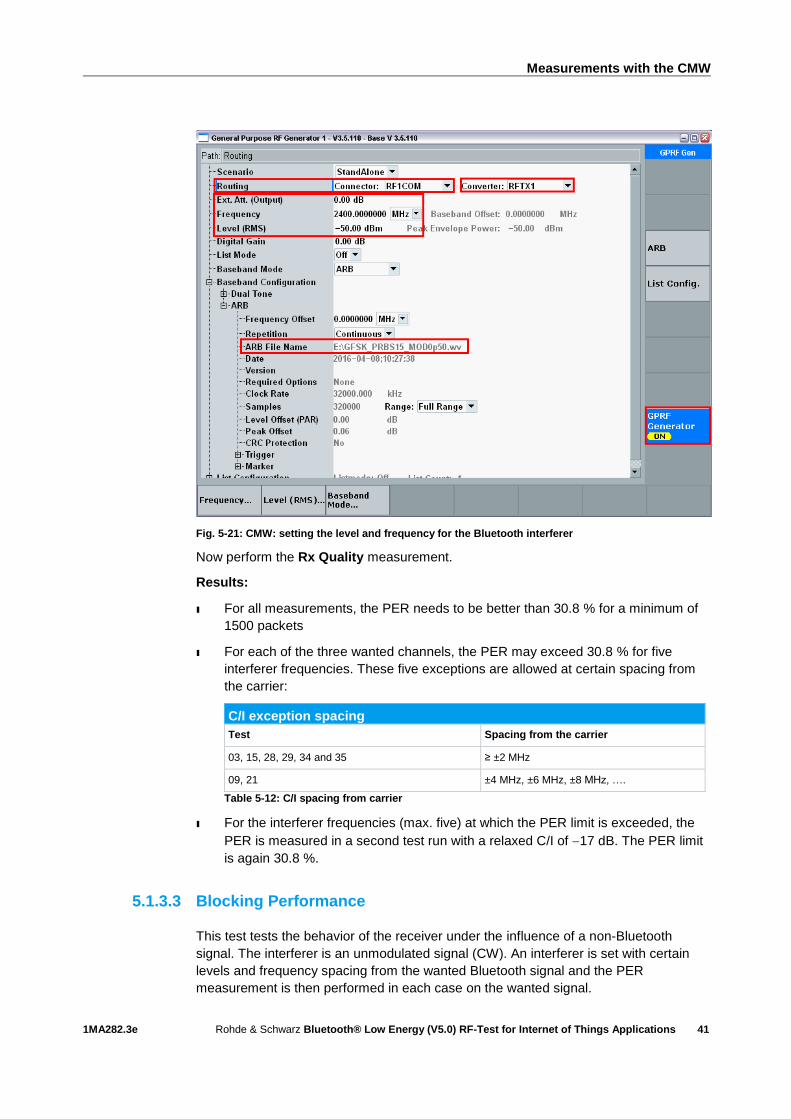
Fig. 5-21: CMW: setting the level and frequency for the Bluetooth interferer
Now perform the Rx Quality measurement.
Results:
ı For all measurements, the PER needs to be better than 30.8 % for a minimum of
1500 packets
ı For each of the three wanted channels, the PER may exceed 30.8 % for five
interferer frequencies. These five exceptions are allowed at certain spacing from
the carrier:
C/I exception spacing
Test Spacing from the carrier
03, 15, 28, 29, 34 and 35 ≥ ±2 MHz
09, 21 ±4 MHz, ±6 MHz, ±8 MHz, ….
Table 5-12: C/I spacing from carrier
ı For the interferer frequencies (max. five) at which the PER limit is exceeded, the
PER is measured in a second test run with a relaxed C/I of 17 dB. The PER limit
is again 30.8 %.
5.1.3.3 Blocking Performance
This test tests the behavior of the receiver under the influence of a non-Bluetooth
signal. The interferer is an unmodulated signal (CW). An interferer is set with certain
levels and frequency spacing from the wanted Bluetooth signal and the PER
measurement is then performed in each case on the wanted signal.

Measurements with the CMW
1MA282.3e Rohde & Schwarz Bluetooth® Low Energy (V5.0) RF-Test for Internet of Things Applications
42
This test is specified for the following PHYs:
Blocking and PHYs
PHY Test number
LE1M 04
LE2M 10
LE1M, SMI 16
LE2M, SMI 22
Table 5-13: Various blocking tests
Fig. 5-22: Blocking performance: For one channel, the packet error rate is measured in the presence
of a CW interferer outside the Bluetooth band. The measurement is repeated after shifting the
interferer by the frequency resolution
Blocking level settings
Interference signal frequency
Wanted signal level Blocking signal level Frequency resolution
30 MHz to 2000 MHz –67 dBm –30 dBm 10 MHz
2003 MHz to 2399 MHz –67 dBm –35 dBm 3 MHz
2484 MHz to 2997 MHz –67 dBm –35 dBm 3 MHz
3000 MHz to 12.75 GHz –67 dBm –30 dBm 25 MHz
Table 5-14: Blocking performance parameters, first test run
This test requires the extended test setup as shown in Fig. 5-2 .
Settings:
ı Signal with PRBS9 and –67 dBm
ı 1500 packets

Measurements with the CMW
1MA282.3e Rohde & Schwarz Bluetooth® Low Energy (V5.0) RF-Test for Internet of Things Applications
43
ı Interferer unmodulated, level depends on frequency spacing (Table 5-9). 30 MHz
start frequency, up to 12.75 GHz in steps as specified in Table 5-14 . The
Bluetooth range (2400 MHz to 2483 MHz) is skipped
The CW interferer can be produced with an additional generator such as the SGS,
SMC or SMF. Here, we describe a solution with the SGS. You can operate the SGS
using the free SGMA GUI software.
Fig. 5-23: Operating the SGS with the SGMA GUI software
Perform the Rx Quality measurement.
Results:
ı 1st test run: At each interferer frequency, 1500 packets are measured. The
frequencies at which a PER > 30.8 % is obtained are recorded. The number of
frequencies recorded here must not exceed ten.
ı 2nd test run: At each frequency recorded during the 1st test run, 1500 packets are
measured at reduced interferer levels of –50 dBm. The frequencies at which a
PER > 30.8 % is obtained are again recorded. The PER limit may be exceeded for
a maximum of three frequencies.
5.1.3.4 Intermodulation Performance
This test is specified for the following PHYs:
Intermodulation and PHYs
PHY Test number
LE1M 05
LE2M 11
LE1M, SMI 17
LE2M, SMI 23
Table 5-15: Various tests for intermodulation
This test tests the behavior of the receiver under the influence of two signals. The first
interferer is an unmodulated signal (CW). The second interferer is a continuously
modulated Bluetooth signal. The interferers are set with certain levels and frequency
spacing from the wanted Bluetooth signal and the PER measurement is then
performed in each case on the wanted signal.

Measurements with the CMW
1MA282.3e Rohde & Schwarz Bluetooth® Low Energy (V5.0) RF-Test for Internet of Things Applications
44
Fig. 5-24: Intermodulation performance: for each of three channels, the packet error rate is measured
in the presence of a CW interferer at a distance n and a Bluetooth interferer at a distance 2n
This test requires the extended test setup as shown in Fig. 5-2 .
Settings:
ı Signal with PRBS9 and –64 dBm
ı 1500 packets
ı n = 3, 4 or 5 (specified by manufacturer)
ı Bluetooth interferer: low energy GFSK with PRBS15 spaced ±2n MHz from
wanted signal, level –50 dBm
ı CW interferer: spaced ±n MHz from wanted signal, level –50 dBm
The CW interferer can be produced with an additional generator such as the SMB,
SGS100A, SMC100A or SMF100A. Here, we describe a solution with the SGS. You
can use the free SGMA GUI software to operate the SGS. See 5.1.3.3.
The Bluetooth interferer can be produced with an additional generator such as the
SMBV or SMW. Here, we describe a solution with the general purpose RF generator
(GPRF) in the CMW. Select ARB as the baseband mode in the GPRF and load the
provided file.
ı GFSK_PRBS15_MOD0p50.wv for LE1M
ı LE2M_INTERFERER_PRBS15.wv for LE2M
This solution is also implemented in the automatic solution with CMWrun (see 5.2). For
details, see 5.1.3.2.
Perform the Rx Quality measurement.
Result:
ı A PER of 30.8 % must be obtained for each of the three channels

Measurements with the CMW
1MA282.3e Rohde & Schwarz Bluetooth® Low Energy (V5.0) RF-Test for Internet of Things Applications
45
5.1.3.5 Maximum Input Signal Level
This test is specified for the following PHYs:
Maximum input signal level and PHYs
PHY Test number
LE1M 06
LE2M 12
LE1M, SMI 18
LE2M, SMI 24
Table 5-16: Various tests for maximum input signal level
For this test, set PRBS9, 1500 packets and a level of –10 dBm. Perform the Rx
Quality measurement.
The following conditions must be fulfilled:
ı PER < 30.8 %
5.1.3.6 PER Report Integrity
This test is specified for all PHYs:
PER report integrity and PHYs
PHY Test number
LE1M 07
LE2M 13
LE1M, SMI 19
LE2M, SMI 25
LE coded, S=2 30
LE coded, S=8 31
LE coded, S=2, SMI 36
LE coded, S=8, SMI 37
Table 5-17: Various tests for PER report integrity
In this test, the CMW transmits an incorrect CRC in every second packet. Switch
Report Integrity to ON and set the level to –30 dBm. Perform the Rx Quality
measurement.

Measurements with the CMW
1MA282.3e Rohde & Schwarz Bluetooth® Low Energy (V5.0) RF-Test for Internet of Things Applications
46
Fig. 5-25: The CMW transmits an incorrect CRC in every second packet
The test needs to be repeated three times with a different random number of packets
in the range from 100 to 1500 packets.
The following conditions must be fulfilled:
ı PER ≥ 50 %
5.2 CMWrun
The CMWrun sequencer software tool is a ready-to-use solution for configuring test
sequences by remote control. It can be enhanced with options and used for all
standards supported by the CMW family – for general RF testing, preconformance and
superior user experience test scenarios.
The software engine is based on the execution of test DLLs (plug-in assemblies). This
architecture not only allows easy and straightforward configuration of test sequences
without knowledge of specific remote programming of the instrument, it also provides
full flexibility in configuring parameters and limits of the test items provided in the
CMWrun package options for the different standards. At the end of the test, an easy-to-
read test report with limits, test results and verdict is generated and made available in
several formats, including csv, txt, xml and pdf.
The CMW KT-057 option (wireless connectivity standards: WiMAX, WLAN, Bluetooth)
provides all of the tests, e.g. as preconformance tests as specified in Table 4-1 and
Table 4-2 as prepackaged modules. The option therefore also covers all of the tests
described in 5.1. The following test plans are supplied:
ı BLE_PHY_5_0_0
- All tests that can be performed with the CMW alone (Not included are the 3
tests: C / I and Receiver sensitivity, Blocking performance tests and
Intermodulation performance tests, which can be found in the Advanced Test
Plans (see below)).
ı BLE_PHY_5_0_0_Advanced_FE-Advanced
- Additional tests with signal generator, advanced frontend
Measurements with the CMW
1MA282.3e Rohde & Schwarz Bluetooth® Low Energy (V5.0) RF-Test for Internet of Things Applications
47
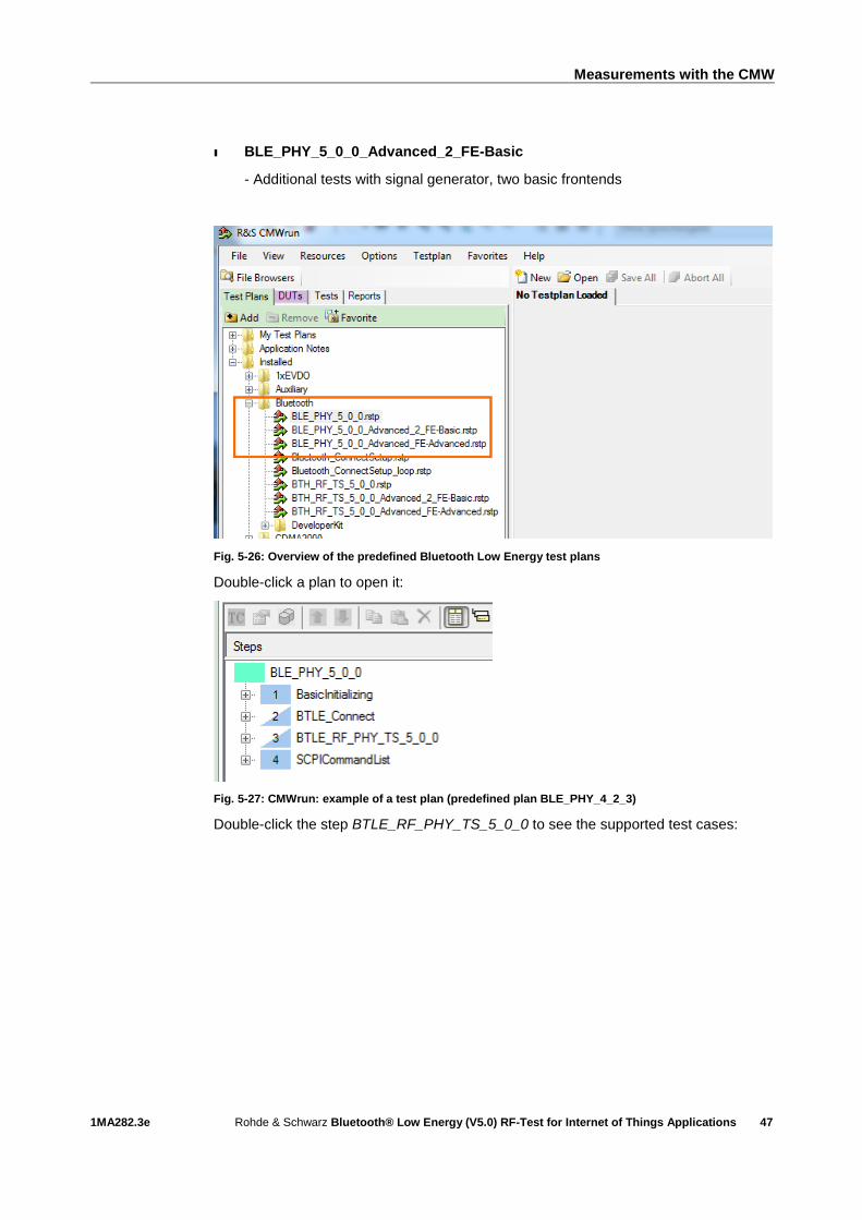
ı BLE_PHY_5_0_0_Advanced_2_FE-Basic
- Additional tests with signal generator, two basic frontends
Fig. 5-26: Overview of the predefined Bluetooth Low Energy test plans
Double-click a plan to open it:
Fig. 5-27: CMWrun: example of a test plan (predefined plan BLE_PHY_4_2_3)
Double-click the step BTLE_RF_PHY_TS_5_0_0 to see the supported test cases:

Measurements with the CMW
1MA282.3e Rohde & Schwarz Bluetooth® Low Energy (V5.0) RF-Test for Internet of Things Applications
48
Fig. 5-28: CMWrun: standard test cases
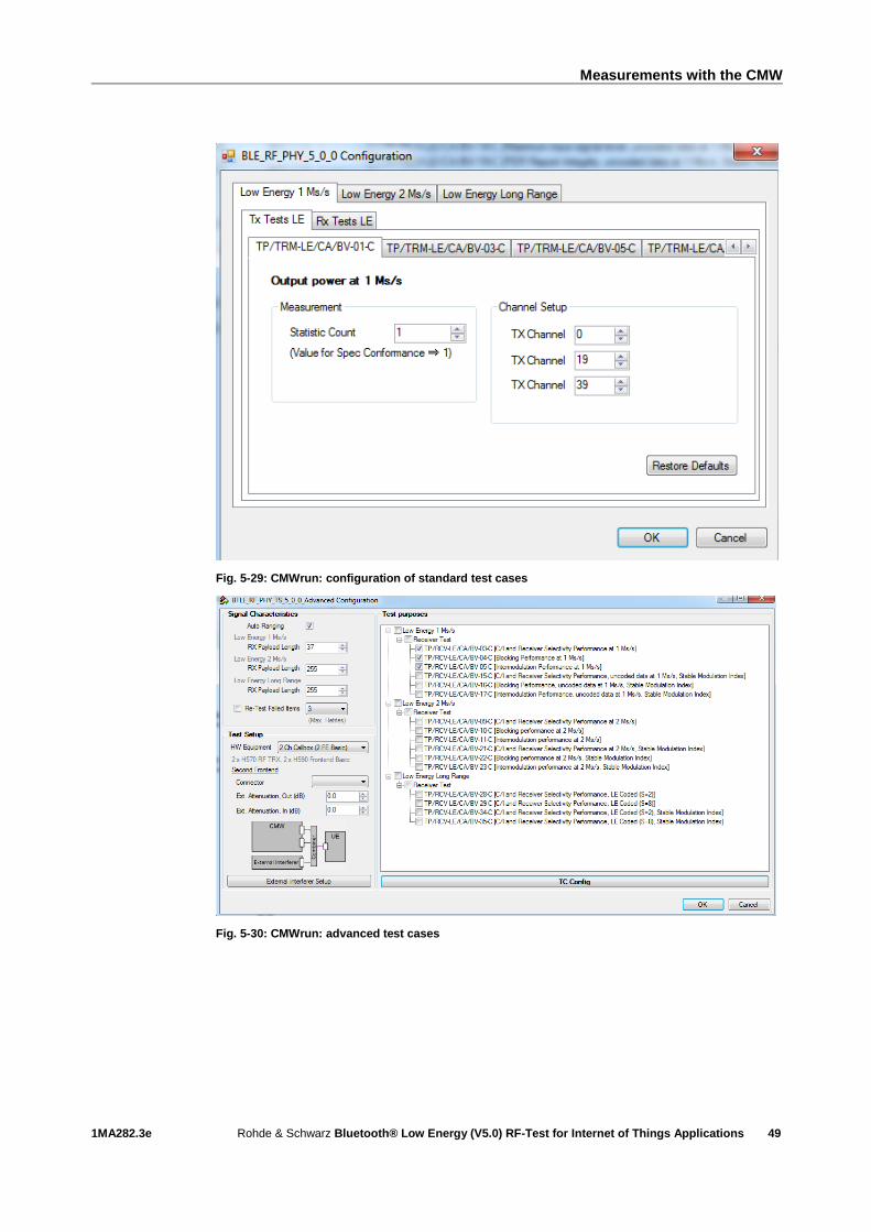
Click TC Config to set additional details:
Measurements with the CMW
1MA282.3e Rohde & Schwarz Bluetooth® Low Energy (V5.0) RF-Test for Internet of Things Applications
49
Fig. 5-29: CMWrun: configuration of standard test cases
Fig. 5-30: CMWrun: advanced test cases

Measurements with Spectrum Analyzer and Signal Generator
1MA282.3e Rohde & Schwarz Bluetooth® Low Energy (V5.0) RF-Test for Internet of Things Applications
50
6 Measurements with Spectrum Analyzer and
Signal Generator
Some of the measurements described in 5 can also be performed using a spectrum
analyzer and a signal generator. Since these instruments do not allow the DUT to be
controlled using the Direct Test mode, the settings specified in the test specification
are configured on the DUT using a PC on which the DUT manufacturer's software has
been installed (Figure 6-1).
6.1 Measurements on Bluetooth LE Transmitter
Test setup:
Figure 6-1: Test setup with spectrum analyzer and PC for signaling
6.1.1 Output Power
This measurement is specified only for LE 1M (test: 01).
Measurement of the output power must be performed as specified in the specification:
with payload pattern PRBS9, the maximum possible packet length supported by the
DUT, maximum power without whitening and without frequency hopping. Use the
manufacturer software to configure the DUT as specified. The output power must be
measured at three different transmit frequencies. Tables 6.1 and 6.2 in the Bluetooth
test specification specify the transmit frequencies to be set on the DUT.
For peripheral and central devices for LE 1M, for example, Table 6.1 specifies the
following three transmit frequencies: ftx = 2402 MHz (low), ftx = 2440 MHz (middle) and
ftx = 2480 MHz (highest). Table 6.2 is for broadcast and observer devices.
Settings on FSV spectrum analyzer:

Measurements with Spectrum Analyzer and Signal Generator
1MA282.3e Rohde & Schwarz Bluetooth® Low Energy (V5.0) RF-Test for Internet of Things Applications
51
1. Press the PRESET key.
2. Press the FREQ key and enter the transmitter frequency value as the center
frequency.
3. Set the resolution bandwidth: press the BW key and enter 3 MHz.
4. Set the video bandwidth: select the Video BW manual menu key and enter 3 MHz.
5. Press the TRACE key and select Trace 1. Press the Detector menu key and
select Positive Peak.
6. In accordance with the test specification, the output power is measured in the time
domain: press the SPAN key and enter 0 Hz or select the Zero Span menu key.
7. Press the TRIG key and select Trg/Gate Source. Press the IF Power menu key
and enter a suitable value for the trigger level so that a stationary trace is
displayed on the screen.
8. Press the AMP key and enter a reference level suitable for the maximum
displayed signal level.
9. Press the SWEEP key and, under Sweeptime Manual, set the sweep time so that
a complete packet or a burst is displayed.
10. Press the TRIG key and use Trigger Offset to move the burst to the center of the
screen ( Figure 6-2).
11. Press the PEAK SEARCH key and record the maximum value of the transmit
power level LPk ( Figure 6-2).
Figure 6-2: Measurement of maximum burst power

Measurements with Spectrum Analyzer and Signal Generator
1MA282.3e Rohde & Schwarz Bluetooth® Low Energy (V5.0) RF-Test for Internet of Things Applications
52
12. Press the AMPT key and use the Unit menu key to select Watt.
In the range of at least 20 % to 80 % of the burst duration, use the marker to read out
as many values as possible and use these values to calculate the average power Pavg.
(Note: Vertical time lines can be used to mark the measurement range. Press the
LINES key, select the Display Line menu key and position the two time lines at a
distance of max. 20 % of the burst length away from the two burst edges. Use the
marker between the two lines to record the measurement data.)
Figure 6-3: Measurement of output power
Calculate the power level with 𝐿𝐴𝑉𝐺 = 10 𝑑𝐵𝑚 𝑙𝑔(𝑃𝐴𝑉𝐺
1 𝑚𝑊).
The following conditions must be fulfilled:
ı ‒20 dBm ≤ LAVG ≤ +10 dBm (up to Core 4.2 without addendum 5)
or
ı ‒20 dBm ≤ LAVG ≤ +20 dBm
and
ı LPK ≤ (LAVG + 3 dB)
Repeat the measurement for the transmit frequencies fTX (middle) and fTX (highest)
specified in the test specification.

Measurements with Spectrum Analyzer and Signal Generator
1MA282.3e Rohde & Schwarz Bluetooth® Low Energy (V5.0) RF-Test for Internet of Things Applications
53
6.1.1.1 Output power test with an R&S Forum script
To automatically execute the measurements described under 6.1.1, a R&S Forum
script (1MA282_Output_PowerVx.x.py) is included with this application note. This
script considerably reduces the amount of work.
Proceed as follows:
1. Open the link 1MA196: Using R&S Forum Application for Instrument Remote
Control and download the R&S Forum setup file.
2. Double-click the .exe file and follow the installation routine.
3. Under Settings -> Instruments…-> Add.., configure the remote control connection
to the spectrum analyzer. For more information, see Application Note 1MA196.
Example:
Figure 6-4: Configuration of remote control connection
9. Download the script file (1MA282_Output_PowerVx.x.py) to a directory previously
created on the PC.
10. Start R&S Forum and load the script with File -> Open….
11. Set the value of the variable "devc" based on the DUT type (devc = 0 for
peripheral and central devices, decv = 1 for broadcaster and observer devices)
(Figure 6-9).
12. Use the "att" (Attenuation) and "rlev" (Reference Level) parameters to adjust the
FSV reference level to the test signal. The trigger level is set with "tlvl". The
parameter "coun" defines the number of measured values from which the average
power value is calculated (Figure 6-9).

Measurements with Spectrum Analyzer and Signal Generator
1MA282.3e Rohde & Schwarz Bluetooth® Low Energy (V5.0) RF-Test for Internet of Things Applications
54
Figure 6-5: Configuration of measurement parameters
13. Use the green arrow key to start the script. On the DUT set the frequencies shown
on the screen and follow the displayed hints:
Note: in order to be able to perform the settings on the device, it is necessary to
switch the analyzer into the manual operating mode with the menu key Local.
After the measurements for three different frequencies have been finished, the result will be displayed (Figure 6-6).

Measurements with Spectrum Analyzer and Signal Generator
1MA282.3e Rohde & Schwarz Bluetooth® Low Energy (V5.0) RF-Test for Internet of Things Applications
55
Figure 6-6: Result of the output power measurement
6.1.2 In-band emissions
This measurement is specified for LE 1M and LE 2M (tests: 03 and 08). In-band
emission measurement (also known as adjacent channel power (ACP)) is performed
under normal operating conditions.
6.1.2.1 In-band emission test 03 (LE 1M, uncoded data at 1 Ms/s)
This test measures whether the spectral in-band RF leakage exceeds the limits defined
in the test specification when the transmitter emits uncoded data at a symbol rate of
1 Ms/s.
Settings on BLE DUT:
1. Switch on Direct Test mode.
2. Set the output power to maximum power.
3. Switch off frequency hopping.
4. Switching off whitening.
5. Symbol rate = 1 Ms/s
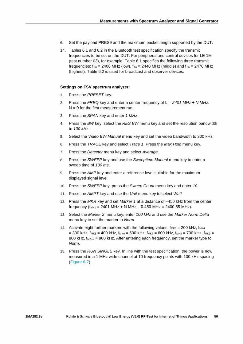
Measurements with Spectrum Analyzer and Signal Generator
1MA282.3e Rohde & Schwarz Bluetooth® Low Energy (V5.0) RF-Test for Internet of Things Applications
56
6. Set the payload PRBS9 and the maximum packet length supported by the DUT.
14. Tables 6.1 and 6.2 in the Bluetooth test specification specify the transmit
frequencies to be set on the DUT. For peripheral and central devices for LE 1M
(test number 03), for example, Table 6.1 specifies the following three transmit
frequencies: fTX = 2406 MHz (low), fTX = 2440 MHz (middle) and fTX = 2476 MHz
(highest). Table 6.2 is used for broadcast and observer devices.
Settings on FSV spectrum analyzer:
1. Press the PRESET key.
2. Press the FREQ key and enter a center frequency of fc = 2401 MHz + N MHz.
N = 0 for the first measurement run.
3. Press the SPAN key and enter 1 MHz.
4. Press the BW key, select the RES BW menu key and set the resolution bandwidth
to 100 kHz.
5. Select the Video BW Manual menu key and set the video bandwidth to 300 kHz.
6. Press the TRACE key and select Trace 1. Press the Max Hold menu key.
7. Press the Detector menu key and select Average.
8. Press the SWEEP key and use the Sweeptime Manual menu key to enter a
sweep time of 100 ms.
9. Press the AMP key and enter a reference level suitable for the maximum
displayed signal level.
10. Press the SWEEP key, press the Sweep Count menu key and enter 10.
11. Press the AMPT key and use the Unit menu key to select Watt
12. Press the MKR key and set Marker 1 at a distance of ‒450 kHz from the center
frequency (fMK1 = 2401 MHz + N MHz ‒ 0.450 MHz = 2400.55 MHz).
13. Select the Marker 2 menu key, enter 100 kHz and use the Marker Norm Delta
menu key to set the marker to Norm.
14. Activate eight further markers with the following values: fMK3 = 200 kHz, fMK4
= 300 kHz, fMK5 = 400 kHz, fMK6 = 500 kHz, fMK7 = 600 kHz, fMK8 = 700 kHz, fMK9 =
800 kHz, fMK10 = 900 kHz. After entering each frequency, set the marker type to
Norm.
15. Press the RUN SINGLE key. In line with the test specification, the power is now
measured in a 1 MHz wide channel at 10 frequency points with 100 kHz spacing
(Figure 6-7).
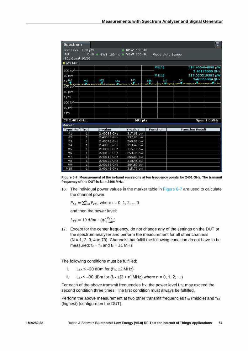
Measurements with Spectrum Analyzer and Signal Generator
1MA282.3e Rohde & Schwarz Bluetooth® Low Energy (V5.0) RF-Test for Internet of Things Applications
57
Figure 6-7: Measurement of the in-band emissions at ten frequency points for 2401 GHz. The transmit
frequency of the DUT is fTX = 2406 MHz.
16. The individual power values in the marker table in Figure 6-7 are used to calculate
the channel power:
𝑃𝑇𝑋 = ∑ 𝑃𝑇𝑋,𝑖9𝑖=0 where i = 0, 1, 2, ... 9
and then the power level:
𝐿𝑇𝑋 = 10 𝑑𝐵𝑚 ∙ 𝑙𝑔(𝑃𝑇𝑋
1 𝑚𝑊)
17. Except for the center frequency, do not change any of the settings on the DUT or
the spectrum analyzer and perform the measurement for all other channels
(N = 1, 2, 3, 4 to 79). Channels that fulfill the following condition do not have to be
measured: fc = ftx and fc = ±1 MHz
The following conditions must be fulfilled:
I. LTX ≤ ‒20 dBm for (fTX ±2 MHz)
II. LTX ≤ ‒30 dBm for (fTX ±[3 + n] MHz) where n = 0, 1, 2, …)
For each of the above transmit frequencies fTX, the power level LTX may exceed the
second condition three times. The first condition must always be fulfilled.
Perform the above measurement at two other transmit frequencies fTX (middle) and fTX
(highest) (configure on the DUT).

Measurements with Spectrum Analyzer and Signal Generator
1MA282.3e Rohde & Schwarz Bluetooth® Low Energy (V5.0) RF-Test for Internet of Things Applications
58
6.1.2.2 In-band emission test 08 (LE 2M, uncoded data at 2 Ms/s)
This test measures whether the spectral in-band RF leakage exceeds the limits defined
in the test specification when the transmitter emits uncoded data at a symbol rate of
2 Ms/s.
Settings on BLE DUT:
1. As described under 6.1.2.1, but with a symbol rate of 2 Ms/s.
Settings on FSV spectrum analyzer:
1. As described under 6.1.2.1.
2. The individual power values in the marker table in Figure 6-7, are used to
calculate the channel power:
𝑃𝑇𝑋 = ∑ 𝑃𝑇𝑋,𝑖9𝑖=0 where i = 0, 1, 2, ...9
and then the power level:
𝐿𝑇𝑋 = 10 𝑑𝐵𝑚 ∙ 𝑙𝑔(𝑃𝑇𝑋
1 𝑚𝑊)
3. Except for the center frequency, do not change any of the settings on the DUT
and spectrum analyzer and perform the measurement for all other channels
(N = 1, 2, 3, 4 to 79). . Channels that fulfill the following condition do not have to
be measured: fc = ftx, fc = ±1 MHz, fc = ±2 MHz and fc = ±3 MHz
The following conditions must be fulfilled:
I. LTX ≤ ‒20 dBm for (fTX ±4 MHz)
II. LTX ≤ ‒20 dBm for (fTX ±5 MHz)
III. LTX ≤ ‒30 dBm for (fTX ±[6 + n] MHz) where n = 0, 1, 2, …)
For each of the above transmit frequencies fTX, the power level LTX may exceed the
third condition three times. The first condition must always be fulfilled.
15. Perform the above measurement at two other transmit frequencies fTX (middle)
and fTX (highest) (set on the DUT).
6.1.2.3 In-band emissions test with an R&S Forum script
To automatically execute the measurements described under 6.1.2.1 and 6.1.2.2, a
R&S Forum script (1MA282_In-Band_EmissionV1.1.py) is included with this
application note. This script considerably reduces the amount of work.
Proceed as follows:
4. Open the link 1MA196: Using R&S Forum Application for Instrument Remote
Control and download the R&S Forum setup file.
5. Double-click the .exe file and follow the installation routine.
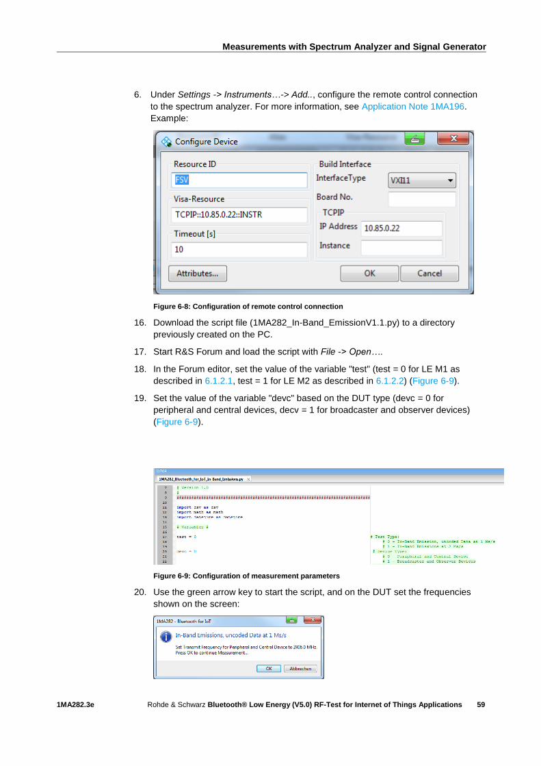
Measurements with Spectrum Analyzer and Signal Generator
1MA282.3e Rohde & Schwarz Bluetooth® Low Energy (V5.0) RF-Test for Internet of Things Applications
59
6. Under Settings -> Instruments…-> Add.., configure the remote control connection
to the spectrum analyzer. For more information, see Application Note 1MA196.
Example:
Figure 6-8: Configuration of remote control connection
16. Download the script file (1MA282_In-Band_EmissionV1.1.py) to a directory
previously created on the PC.
17. Start R&S Forum and load the script with File -> Open….
18. In the Forum editor, set the value of the variable "test" (test = 0 for LE M1 as
described in 6.1.2.1, test = 1 for LE M2 as described in 6.1.2.2) (Figure 6-9).
19. Set the value of the variable "devc" based on the DUT type (devc = 0 for
peripheral and central devices, decv = 1 for broadcaster and observer devices)
(Figure 6-9).
Figure 6-9: Configuration of measurement parameters
20. Use the green arrow key to start the script, and on the DUT set the frequencies
shown on the screen:
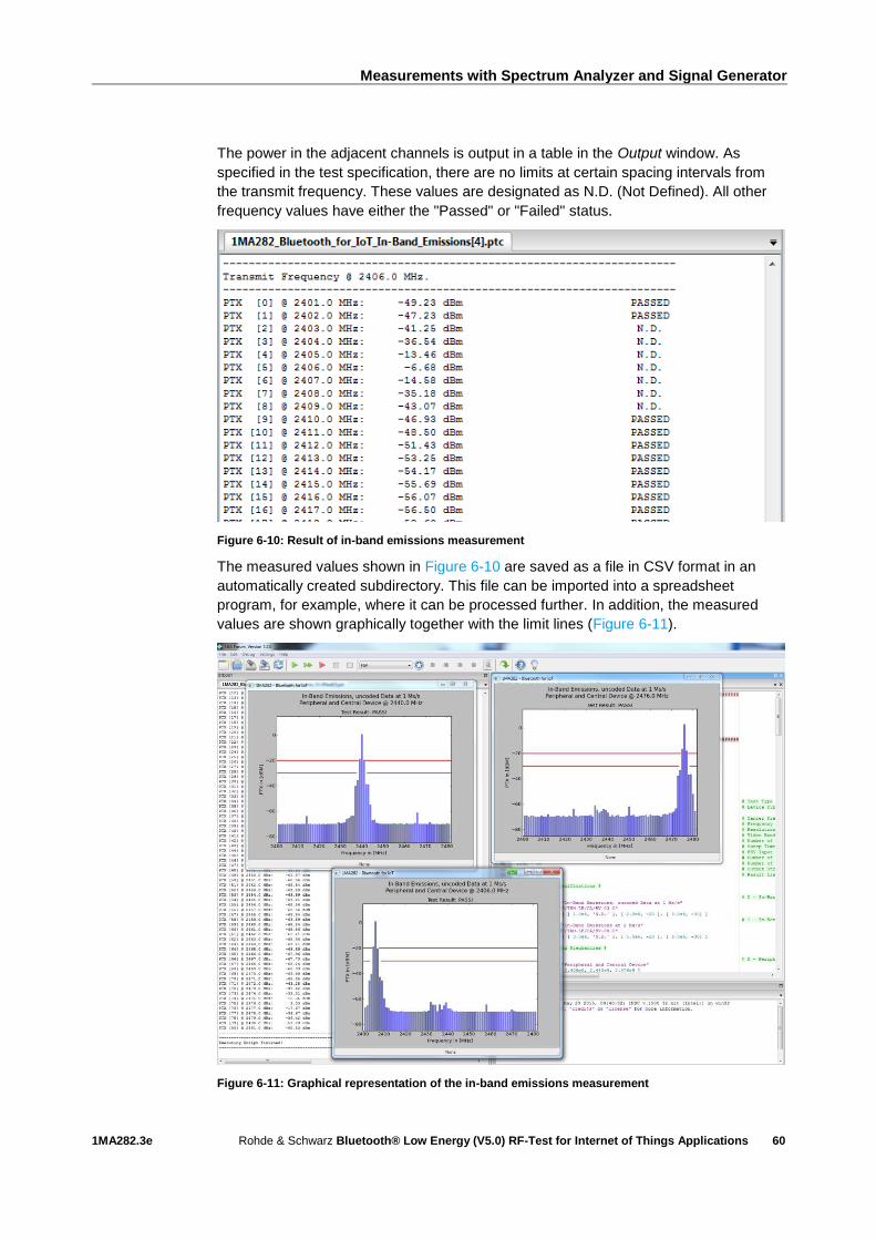
Measurements with Spectrum Analyzer and Signal Generator
1MA282.3e Rohde & Schwarz Bluetooth® Low Energy (V5.0) RF-Test for Internet of Things Applications
60
The power in the adjacent channels is output in a table in the Output window. As
specified in the test specification, there are no limits at certain spacing intervals from
the transmit frequency. These values are designated as N.D. (Not Defined). All other
frequency values have either the "Passed" or "Failed" status.
Figure 6-10: Result of in-band emissions measurement
The measured values shown in Figure 6-10 are saved as a file in CSV format in an
automatically created subdirectory. This file can be imported into a spreadsheet
program, for example, where it can be processed further. In addition, the measured
values are shown graphically together with the limit lines (Figure 6-11).
Figure 6-11: Graphical representation of the in-band emissions measurement
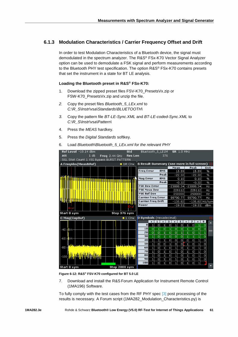
Measurements with Spectrum Analyzer and Signal Generator
1MA282.3e Rohde & Schwarz Bluetooth® Low Energy (V5.0) RF-Test for Internet of Things Applications
61
6.1.3 Modulation Characteristics / Carrier Frequency Offset and Drift
In order to test Modulation Characteristics of a Bluetooth device, the signal must
demodulated in the spectrum analyzer. The R&S® FSx-K70 Vector Signal Analyzer
option can be used to demodulate a FSK signal and perform measurements according
to the Bluetooth PHY test specification. The option R&S® FSx-K70 contains presets
that set the instrument in a state for BT LE analysis.
Loading the Bluetooth preset in R&S® FSx-K70:
1. Download the zipped preset files FSV-K70_PresetsVx.zip or
FSW-K70_PresetsVx.zip and unzip the file.
2. Copy the preset files Bluetooth_5_LEx.xml to
C:\R_S\Instr\vsa\Standards\BLUETOOTH\
3. Copy the pattern file BT-LE-Sync.XML and BT-LE-coded-Sync.XML to
C:\R_S\Instr\vsa\Pattern\
4. Press the MEAS hardkey.
5. Press the Digital Standards softkey.
6. Load Bluetooth\Bluetooth_5_LEx.xml for the relevant PHY
Figure 6-12: R&S® FSV-K70 configured for BT 5.0 LE
7. Download and install the R&S Forum Application for Instrument Remote Control
(1MA196) Software.
To fully comply with the test cases from the RF PHY spec [3] post processing of the
results is necessary. A Forum script (1MA282_Modulation_Characteristics.py) is
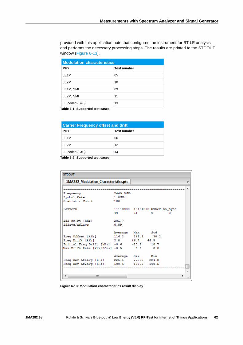
Measurements with Spectrum Analyzer and Signal Generator
1MA282.3e Rohde & Schwarz Bluetooth® Low Energy (V5.0) RF-Test for Internet of Things Applications
62
provided with this application note that configures the instrument for BT LE analysis
and performs the necessary processing steps. The results are printed to the STDOUT
window (Figure 6-13).
Modulation characteristics
PHY Test number
LE1M 05
LE2M 10
LE1M, SMI 09
LE2M, SMI 11
LE coded (S=8) 13
Table 6-1: Supported test cases
Carrier Frequency offset and drift
PHY Test number
LE1M 06
LE2M 12
LE coded (S=8) 14
Table 6-2: Supported test cases
Figure 6-13: Modulation characteristics result display

Measurements with Spectrum Analyzer and Signal Generator
1MA282.3e Rohde & Schwarz Bluetooth® Low Energy (V5.0) RF-Test for Internet of Things Applications
63
6.2 Measurements on Bluetooth LE receiver
The packet error rate (PER) is measured in order to assess the receive quality of a
Bluetooth LE receiver. The packet error rate is calculated in the DUT itself. The DUT
reports the PER via Direct Test mode to the software provided by the manufacturer of
the receiver. This software is also used to configure the necessary settings on the
DUT.
Important: For all receiver measurements described below, the signal generator must
transmit to the receiver a BLE wanted signal consisting of at least 1500 packets. It
suffices to transmit the packet length only once for a PER measurement. The signal
generator must be in the Single trigger mode when the PER is measured. This is
configured on the SMBV100A as follows:
1. In the Bluetooth window scroll down with the arrow key and select
Trigger/Marker…:
2. Under Mode, select Single:
3. Transmit the signal to the receiver by clicking Execute Trigger:

Measurements with Spectrum Analyzer and Signal Generator
1MA282.3e Rohde & Schwarz Bluetooth® Low Energy (V5.0) RF-Test for Internet of Things Applications
64
In this application note, the SMBV100A vector signal generator is used to generate the
BLE signals. However, the SGT100A vector RF source can be used as a cost-effective
alternative. Since up to three signal generators are needed for the receiver tests, the
SGT100A with its displayless design offers an extremely compact solution that takes
up little space on the workbench. The R&S SGMA GUI software is used to configure
the settings. The software can control up to 12 devices simultaneously. Connection to
the PC is via USB or LAN. The R&S WINIQSIM simulation software generates the
standard-compliant BLE baseband signals. The generated digital waveforms are
imported into the SGT100A and processed further.
Figure 6-14: SGS100A vector RF source with R&S SGMA GUI operating software
6.2.1 Receiver sensitivity
This test verifies whether the receiver sensitivity is within the limits defined by the test
specification when a non-ideal transmit signal is fed to the receiver. The generated
transmit signal varies within the limits defined by the specification and is therefore not
ideal. The signal is generated by a vector signal generator, e.g. the SMBV100A.
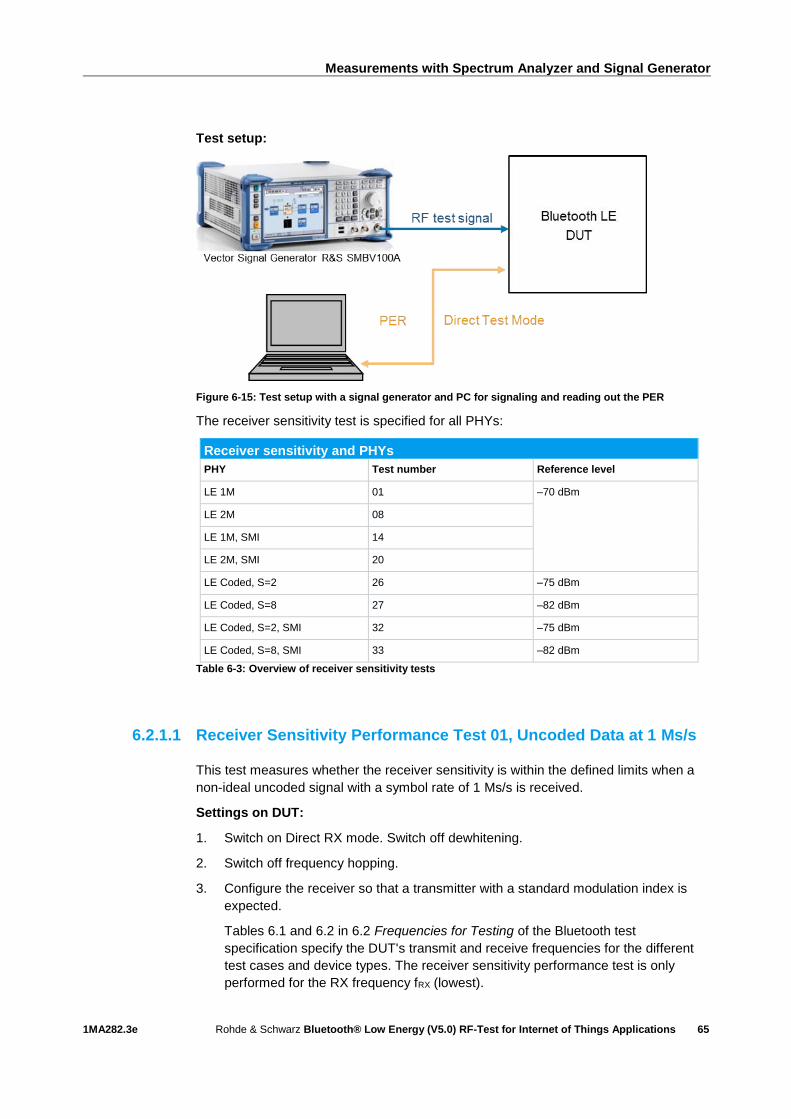
Measurements with Spectrum Analyzer and Signal Generator
1MA282.3e Rohde & Schwarz Bluetooth® Low Energy (V5.0) RF-Test for Internet of Things Applications
65
Test setup:
Figure 6-15: Test setup with a signal generator and PC for signaling and reading out the PER
The receiver sensitivity test is specified for all PHYs:
Receiver sensitivity and PHYs
PHY Test number Reference level
LE 1M 01 ‒70 dBm
LE 2M 08
LE 1M, SMI 14
LE 2M, SMI 20
LE Coded, S=2 26 ‒75 dBm
LE Coded, S=8 27 ‒82 dBm
LE Coded, S=2, SMI 32 ‒75 dBm
LE Coded, S=8, SMI 33 ‒82 dBm
Table 6-3: Overview of receiver sensitivity tests
6.2.1.1 Receiver Sensitivity Performance Test 01, Uncoded Data at 1 Ms/s
This test measures whether the receiver sensitivity is within the defined limits when a
non-ideal uncoded signal with a symbol rate of 1 Ms/s is received.
Settings on DUT:
1. Switch on Direct RX mode. Switch off dewhitening.
2. Switch off frequency hopping.
3. Configure the receiver so that a transmitter with a standard modulation index is
expected.
Tables 6.1 and 6.2 in 6.2 Frequencies for Testing of the Bluetooth test
specification specify the DUT's transmit and receive frequencies for the different
test cases and device types. The receiver sensitivity performance test is only
performed for the RX frequency fRX (lowest).
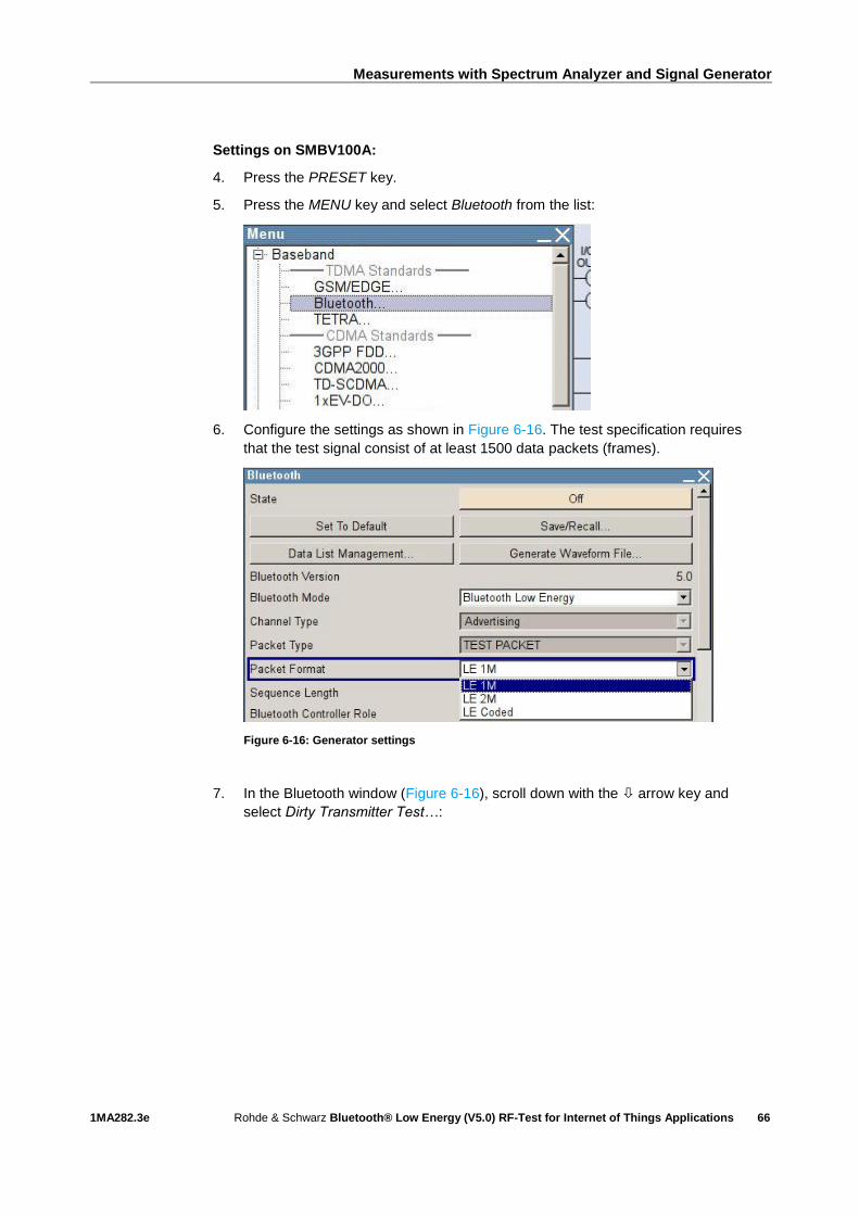
Measurements with Spectrum Analyzer and Signal Generator
1MA282.3e Rohde & Schwarz Bluetooth® Low Energy (V5.0) RF-Test for Internet of Things Applications
66
Settings on SMBV100A:
4. Press the PRESET key.
5. Press the MENU key and select Bluetooth from the list:
6. Configure the settings as shown in Figure 6-16. The test specification requires
that the test signal consist of at least 1500 data packets (frames).
Figure 6-16: Generator settings
7. In the Bluetooth window (Figure 6-16), scroll down with the arrow key and
select Dirty Transmitter Test…:
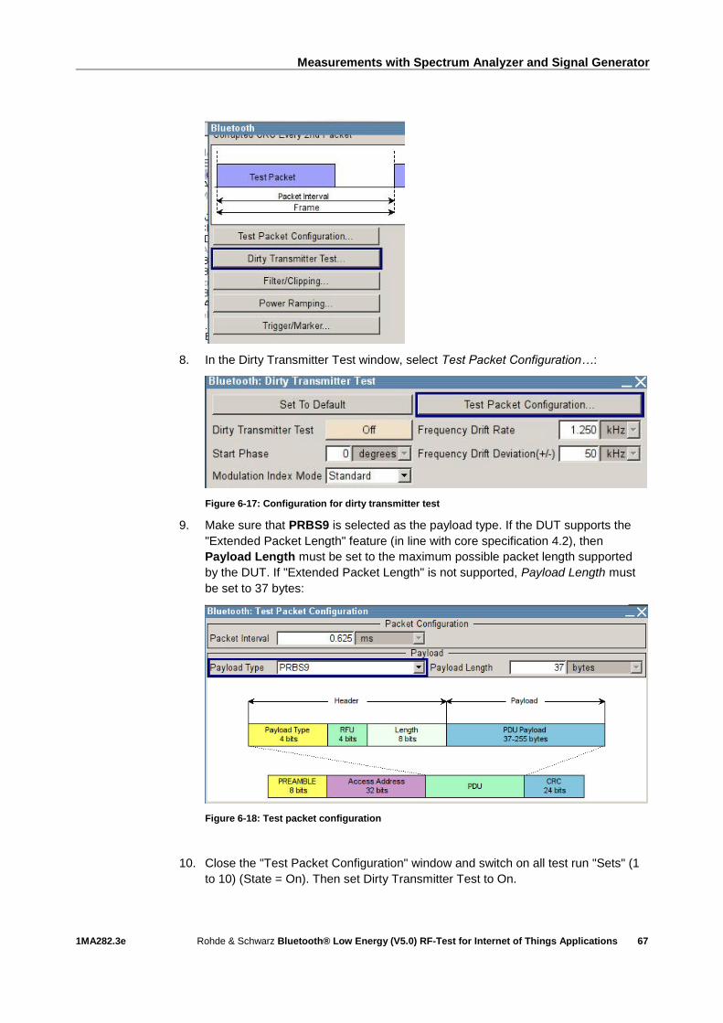
Measurements with Spectrum Analyzer and Signal Generator
1MA282.3e Rohde & Schwarz Bluetooth® Low Energy (V5.0) RF-Test for Internet of Things Applications
67
8. In the Dirty Transmitter Test window, select Test Packet Configuration…:
Figure 6-17: Configuration for dirty transmitter test
9. Make sure that PRBS9 is selected as the payload type. If the DUT supports the
"Extended Packet Length" feature (in line with core specification 4.2), then
Payload Length must be set to the maximum possible packet length supported
by the DUT. If "Extended Packet Length" is not supported, Payload Length must
be set to 37 bytes:
Figure 6-18: Test packet configuration
10. Close the "Test Packet Configuration" window and switch on all test run "Sets" (1
to 10) (State = On). Then set Dirty Transmitter Test to On.

Measurements with Spectrum Analyzer and Signal Generator
1MA282.3e Rohde & Schwarz Bluetooth® Low Energy (V5.0) RF-Test for Internet of Things Applications
68
Figure 6-19: Dirty transmitter test settings in line the with test specification
11. Press the FREQ key and enter the value of fRX (lowest).
12. Press the LEVEL key and enter ‒70 dBm (see Table 6-3). Note: Since the test
specification defines the level at the input of the Bluetooth receiver, the additional
cable loss must be taken into account when entering the reference level.
13. Start the calculation of the Bluetooth test signal with State = On. After the
calculation, press the RF ON/OFF key to switch on the Bluetooth RF signal.
With the described settings, the vector signal generator generates a test signal
compliant with the test specification. The test signal consists of a series of packets
(Figure 6-18). The characteristics of this signal changes after every 50 packets.
This change is described by 10 different test run "Sets". As can be seen in Figure
6-19, the carrier frequency offset, the modulation index and the symbol timing
error all change based on a fixed pattern. When all 10 test runs have been
completed, testing begins again with test run "Set 1" until the number of packets
entered under Sequence Length is reached (for trigger mode Single). In addition
to the specified parameters, frequency modulation is used to add a time frequency
drift to the test signal. The signal to be modulated is sinusoidal with a frequency
deviation of 50 kHz and a modulation frequency of 1250 Hz (Figure 6-19).
The following condition must be fulfilled:
ı PER < 30.8 % (for Payload Length = 37 bytes and at least 1500 packets). For
other payload lengths, the PER limit is given in Table 6.4: PER level by maximum
payload length in receiver of the test specification.

Measurements with Spectrum Analyzer and Signal Generator
1MA282.3e Rohde & Schwarz Bluetooth® Low Energy (V5.0) RF-Test for Internet of Things Applications
69
6.2.1.2 Receiver Sensitivity Performance Test 08, Uncoded Data at 2 Ms/s
This test measures whether the receiver sensitivity is within the defined limits when a
non-ideal uncoded signal with a symbol rate of 2 Ms/s is received.
Settings on DUT:
1. Switch on Direct RX mode. Switch off dewhitening.
2. Switch off frequency hopping.
3. Configure the receiver so that a transmitter with a standard modulation index is
expected.
Tables 6.1 and 6.2 in 6.2 Frequencies for Testing of the Bluetooth test
specification specify the DUT's transmit and receive frequencies for the different
test cases and device types. The receiver sensitivity performance test is only
performed for the RX frequency fRX (lowest).
Settings on SMBV100A:
4. Press the PRESET key.
5. Press the MENU key and select Bluetooth from the list:
6. Configure the settings as shown in Figure 6-20. The test specification requires
that the test signal consist of at least 1500 data packets (frames).
Figure 6-20: Generator settings

Measurements with Spectrum Analyzer and Signal Generator
1MA282.3e Rohde & Schwarz Bluetooth® Low Energy (V5.0) RF-Test for Internet of Things Applications
70
7. In the Bluetooth window, scroll down with the arrow key and select Dirty
Transmitter Test…:
8. In the Dirty Transmitter Test window, select Test Packet Configuration…:
Figure 6-21: Configuration for dirty transmitter test
9. Make sure that PRBS9 is selected as the payload type. If the DUT supports the
"Extended Packet Length" feature (in line with core specification 4.2), then
Payload Length must be set to the maximum possible packet length supported
by the DUT. If "Extended Packet Length" is not supported, Payload Length must
be set to 37 bytes:
Figure 6-22: Test packet configuration
10. Close the "Test Packet Configuration" window and switch on all test run "Sets" (1
to 10) (State = On). Then set Dirty Transmitter Test to On.

Measurements with Spectrum Analyzer and Signal Generator
1MA282.3e Rohde & Schwarz Bluetooth® Low Energy (V5.0) RF-Test for Internet of Things Applications
71
Figure 6-23: Dirty transmitter test settings in line with the test specification
11. Press the FREQ key and enter the value of fRX (lowest).
12. Press the LEVEL key and enter ‒70 dBm (see Table 6-3). Note: Since the test
specification defines the level at the input of the Bluetooth receiver, the additional
cable loss must be taken into account when entering the reference level.
13. Start the calculation of the Bluetooth test signal with State = On. After the
calculation, press the RF ON/OFF key to switch on the Bluetooth RF signal.
With the described settings, the vector signal generator generates a test signal
compliant with the test specification.
The following condition must be fulfilled:
ı PER < 30.8 % (for Payload Length = 37 bytes and at least 1500 packets). For
other payload lengths, the PER limit is given in Table 6.4: PER level by maximum
payload length in receiver of the test specification.
6.2.1.3 Receiver Sensitivity Performance Test 14, Uncoded Data at 1 Ms/s,
Stable Modulation Index
This test measures whether the receiver sensitivity is within the defined limits when a
non-ideal uncoded signal with a symbol rate of 1 Ms/s is received. Here, the receiver
expects a transmitter with a stable modulation index.
Settings on DUT:
I As described under 6.2.1.1, but configure the receiver so that a transmitter with a
stable modulation index is expected.
Settings on SMBV100A:
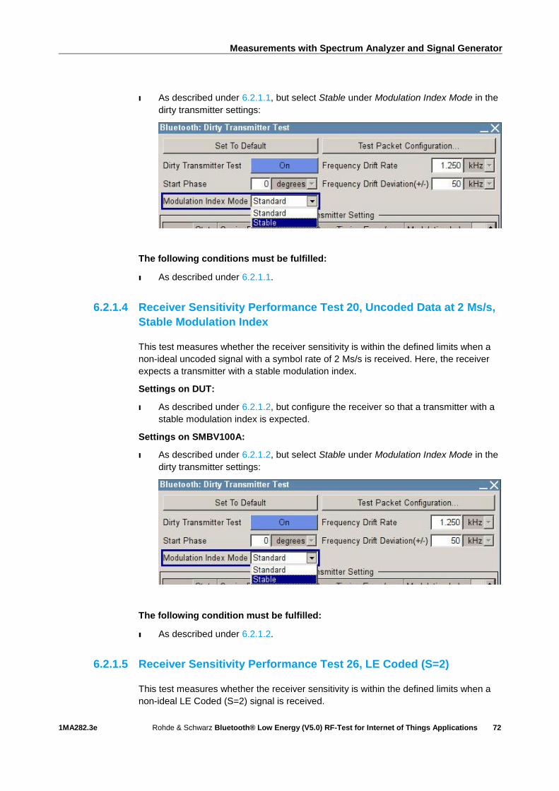
Measurements with Spectrum Analyzer and Signal Generator
1MA282.3e Rohde & Schwarz Bluetooth® Low Energy (V5.0) RF-Test for Internet of Things Applications
72
I As described under 6.2.1.1, but select Stable under Modulation Index Mode in the
dirty transmitter settings:
The following conditions must be fulfilled:
ı As described under 6.2.1.1.
6.2.1.4 Receiver Sensitivity Performance Test 20, Uncoded Data at 2 Ms/s,
Stable Modulation Index
This test measures whether the receiver sensitivity is within the defined limits when a
non-ideal uncoded signal with a symbol rate of 2 Ms/s is received. Here, the receiver
expects a transmitter with a stable modulation index.
Settings on DUT:
I As described under 6.2.1.2, but configure the receiver so that a transmitter with a
stable modulation index is expected.
Settings on SMBV100A:
I As described under 6.2.1.2, but select Stable under Modulation Index Mode in the
dirty transmitter settings:
The following condition must be fulfilled:
ı As described under 6.2.1.2.
6.2.1.5 Receiver Sensitivity Performance Test 26, LE Coded (S=2)
This test measures whether the receiver sensitivity is within the defined limits when a
non-ideal LE Coded (S=2) signal is received.

Measurements with Spectrum Analyzer and Signal Generator
1MA282.3e Rohde & Schwarz Bluetooth® Low Energy (V5.0) RF-Test for Internet of Things Applications
73
Settings on DUT:
1. Switch on Direct RX mode. Switch off dewhitening.
2. Switch off frequency hopping.
3. Configure the receiver so that a transmitter with a standard modulation index is
expected.
Tables 6.1 and 6.2 in 6.2 Frequencies for Testing of the Bluetooth test
specification specify the DUT's transmit and receive frequencies for the different
test cases and device types. The receiver sensitivity performance test is only
performed for the RX frequency fRX (lowest).
Settings on SMBV100A:
4. Press the PRESET key.
5. Press the MENU key and select Bluetooth from the list:
6. Configure the settings as shown in Figure 6-24. The test specification requires
that the test signal consist of at least 1500 data packets (frames).
Figure 6-24: Generator settings
7. In the Bluetooth window (Figure 6-24), scroll down with the arrow key and
select Dirty Transmitter Test…:
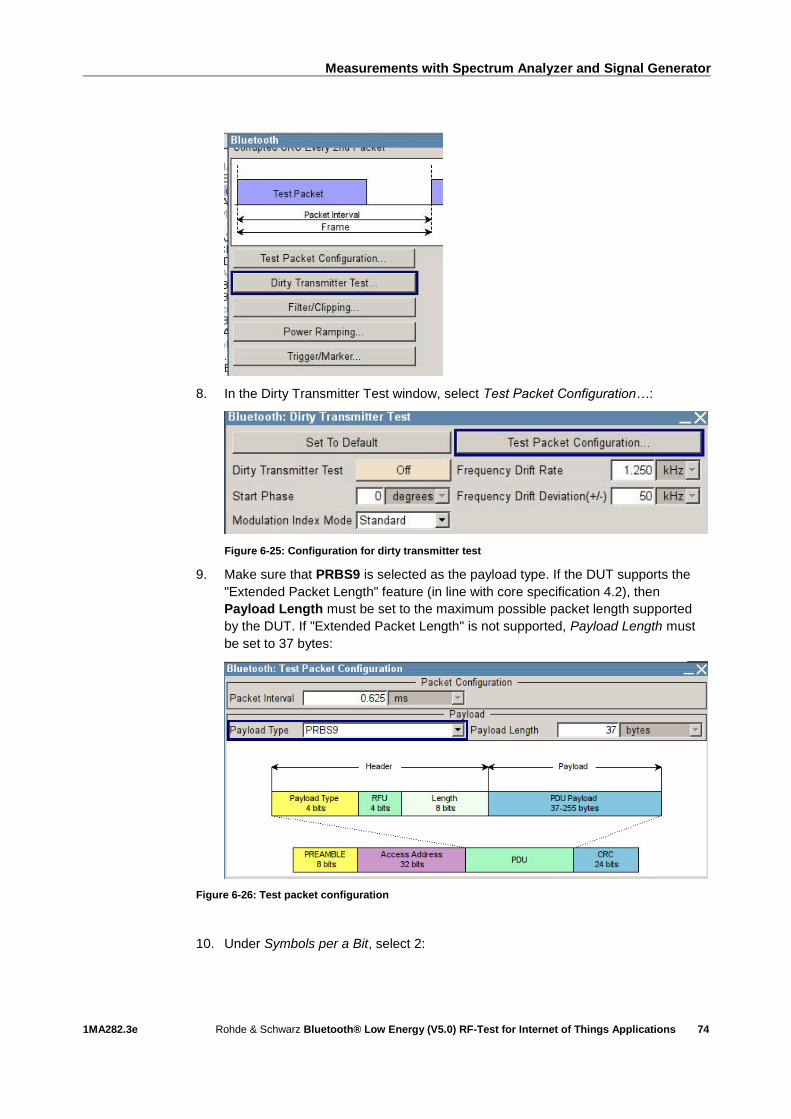
Measurements with Spectrum Analyzer and Signal Generator
1MA282.3e Rohde & Schwarz Bluetooth® Low Energy (V5.0) RF-Test for Internet of Things Applications
74
8. In the Dirty Transmitter Test window, select Test Packet Configuration…:
Figure 6-25: Configuration for dirty transmitter test
9. Make sure that PRBS9 is selected as the payload type. If the DUT supports the
"Extended Packet Length" feature (in line with core specification 4.2), then
Payload Length must be set to the maximum possible packet length supported
by the DUT. If "Extended Packet Length" is not supported, Payload Length must
be set to 37 bytes:
Figure 6-26: Test packet configuration
10. Under Symbols per a Bit, select 2:

Measurements with Spectrum Analyzer and Signal Generator
1MA282.3e Rohde & Schwarz Bluetooth® Low Energy (V5.0) RF-Test for Internet of Things Applications
75
11. Close the "Test Packet Configuration" window and switch on all test run "Sets" (1
to 10) (State = On). Then set Dirty Transmitter Test to On.
Figure 6-27: Dirty transmitter test settings in line with the test specification
12. Press the FREQ key and enter the value of fRX (lowest).
13. Press the LEVEL key and enter ‒75 dBm (see Table 6-3). Note: Since the test
specification defines the level at the input of the Bluetooth receiver, the additional
cable loss must be taken into account when entering the reference level.
14. Start the calculation of the Bluetooth test signal with State = On. After the
calculation, press the RF ON/OFF key to switch on the Bluetooth RF signal.
With the described settings, the vector signal generator generates a test signal
compliant with the test specification.
The following condition must be fulfilled:
ı PER < 30.8 % (for Payload Length = 37 bytes and at least 1500 packets). For
other payload lengths, the PER limit is given in Table 6.4: PER level by maximum
payload length in receiver of the test specification.
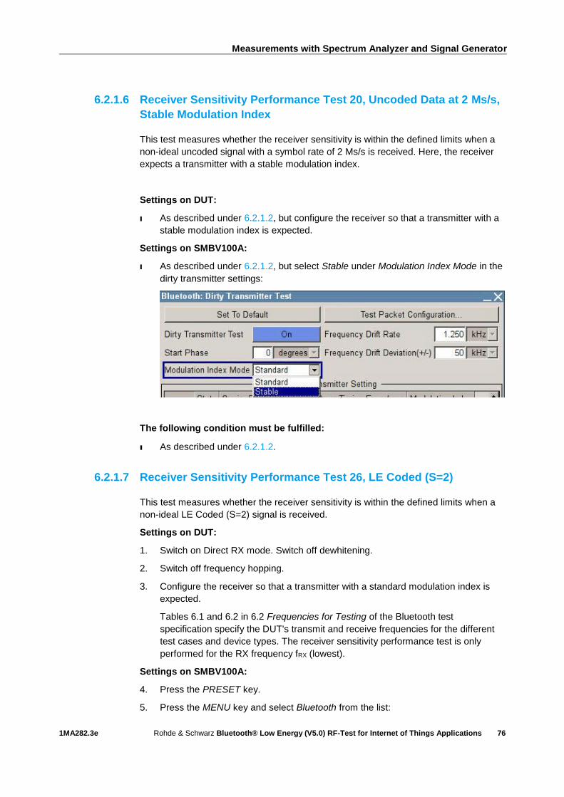
Measurements with Spectrum Analyzer and Signal Generator
1MA282.3e Rohde & Schwarz Bluetooth® Low Energy (V5.0) RF-Test for Internet of Things Applications
76
6.2.1.6 Receiver Sensitivity Performance Test 20, Uncoded Data at 2 Ms/s,
Stable Modulation Index
This test measures whether the receiver sensitivity is within the defined limits when a
non-ideal uncoded signal with a symbol rate of 2 Ms/s is received. Here, the receiver
expects a transmitter with a stable modulation index.
Settings on DUT:
I As described under 6.2.1.2, but configure the receiver so that a transmitter with a
stable modulation index is expected.
Settings on SMBV100A:
I As described under 6.2.1.2, but select Stable under Modulation Index Mode in the
dirty transmitter settings:
The following condition must be fulfilled:
ı As described under 6.2.1.2.
6.2.1.7 Receiver Sensitivity Performance Test 26, LE Coded (S=2)
This test measures whether the receiver sensitivity is within the defined limits when a
non-ideal LE Coded (S=2) signal is received.
Settings on DUT:
1. Switch on Direct RX mode. Switch off dewhitening.
2. Switch off frequency hopping.
3. Configure the receiver so that a transmitter with a standard modulation index is
expected.
Tables 6.1 and 6.2 in 6.2 Frequencies for Testing of the Bluetooth test
specification specify the DUT's transmit and receive frequencies for the different
test cases and device types. The receiver sensitivity performance test is only
performed for the RX frequency fRX (lowest).
Settings on SMBV100A:
4. Press the PRESET key.
5. Press the MENU key and select Bluetooth from the list:

Measurements with Spectrum Analyzer and Signal Generator
1MA282.3e Rohde & Schwarz Bluetooth® Low Energy (V5.0) RF-Test for Internet of Things Applications
77
6. Configure the settings as shown in Figure 6-24. The test specification requires
that the test signal consist of at least 1500 data packets (frames).
Figure 6-28: Generator settings
7. In the Bluetooth window (Figure 6-24), scroll down with the arrow key and
select Dirty Transmitter Test…:
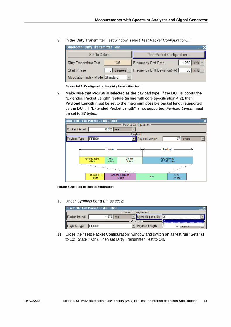
Measurements with Spectrum Analyzer and Signal Generator
1MA282.3e Rohde & Schwarz Bluetooth® Low Energy (V5.0) RF-Test for Internet of Things Applications
78
8. In the Dirty Transmitter Test window, select Test Packet Configuration…:
Figure 6-29: Configuration for dirty transmitter test
9. Make sure that PRBS9 is selected as the payload type. If the DUT supports the
"Extended Packet Length" feature (in line with core specification 4.2), then
Payload Length must be set to the maximum possible packet length supported
by the DUT. If "Extended Packet Length" is not supported, Payload Length must
be set to 37 bytes:
Figure 6-30: Test packet configuration
10. Under Symbols per a Bit, select 2:
11. Close the "Test Packet Configuration" window and switch on all test run "Sets" (1
to 10) (State = On). Then set Dirty Transmitter Test to On.

Measurements with Spectrum Analyzer and Signal Generator
1MA282.3e Rohde & Schwarz Bluetooth® Low Energy (V5.0) RF-Test for Internet of Things Applications
79
Figure 6-31: Dirty transmitter test settings in line with the test specification
12. Press the FREQ key and enter the value of fRX (lowest).
13. Press the LEVEL key and enter ‒75 dBm (see Table 6-3). Note: Since the test
specification defines the level at the input of the Bluetooth receiver, the additional
cable loss must be taken into account when entering the reference level.
14. Start the calculation of the Bluetooth test signal with State = On. After the
calculation, press the RF ON/OFF key to switch on the Bluetooth RF signal.
With the described settings, the vector signal generator generates a test signal
compliant with the test specification.
The following condition must be fulfilled:
ı PER < 30.8 % (for Payload Length = 37 bytes and at least 1500 packets). For
other payload lengths, the PER limit is given in Table 6.4: PER level by maximum
payload length in receiver of the test specification.
6.2.1.8 Receiver Sensitivity Performance Test 27, LE Coded (S=8)
This test measures whether the receiver sensitivity is within the defined limits when a
non-ideal LE Coded (S=8) signal is received.
Settings on DUT:
1. Switch on Direct RX mode. Switch off dewhitening.
2. Switch off frequency hopping.
3. Configure the receiver so that a transmitter with a standard modulation index is
expected.
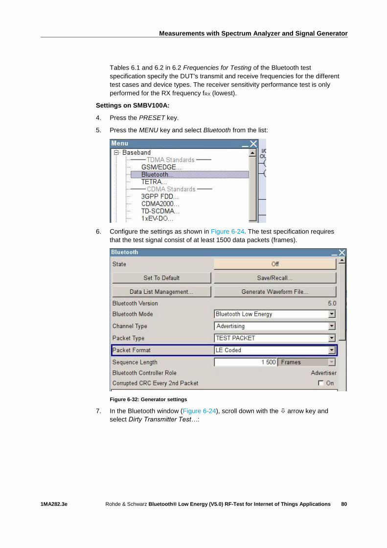
Measurements with Spectrum Analyzer and Signal Generator
1MA282.3e Rohde & Schwarz Bluetooth® Low Energy (V5.0) RF-Test for Internet of Things Applications
80
Tables 6.1 and 6.2 in 6.2 Frequencies for Testing of the Bluetooth test
specification specify the DUT's transmit and receive frequencies for the different
test cases and device types. The receiver sensitivity performance test is only
performed for the RX frequency fRX (lowest).
Settings on SMBV100A:
4. Press the PRESET key.
5. Press the MENU key and select Bluetooth from the list:
6. Configure the settings as shown in Figure 6-24. The test specification requires
that the test signal consist of at least 1500 data packets (frames).
Figure 6-32: Generator settings
7. In the Bluetooth window (Figure 6-24), scroll down with the arrow key and
select Dirty Transmitter Test…:
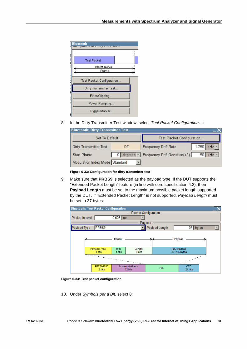
Measurements with Spectrum Analyzer and Signal Generator
1MA282.3e Rohde & Schwarz Bluetooth® Low Energy (V5.0) RF-Test for Internet of Things Applications
81
8. In the Dirty Transmitter Test window, select Test Packet Configuration…:
Figure 6-33: Configuration for dirty transmitter test
9. Make sure that PRBS9 is selected as the payload type. If the DUT supports the
"Extended Packet Length" feature (in line with core specification 4.2), then
Payload Length must be set to the maximum possible packet length supported
by the DUT. If "Extended Packet Length" is not supported, Payload Length must
be set to 37 bytes:
Figure 6-34: Test packet configuration
10. Under Symbols per a Bit, select 8:

Measurements with Spectrum Analyzer and Signal Generator
1MA282.3e Rohde & Schwarz Bluetooth® Low Energy (V5.0) RF-Test for Internet of Things Applications
82
11. Close the "Test Packet Configuration" window and switch on all test run "Sets" (1
to 10) (State = On). Then set Dirty Transmitter Test to On.
Figure 6-35: Dirty transmitter test settings in line with the test specification
12. Press the FREQ key and enter the value of fRX (lowest).
13. Press the LEVEL key and enter ‒82 dBm (see Table 6-3). Note: Since the test
specification defines the level at the input of the Bluetooth receiver, the additional
cable loss must be taken into account when entering the reference level.
14. Start the calculation of the Bluetooth test signal with State = On. After the
calculation, press the RF ON/OFF key to switch on the Bluetooth RF signal.
With the described settings, the vector signal generator generates a test signal
compliant with the test specification.
The following condition must be fulfilled:
ı PER < 30.8 % (for Payload Length = 37 bytes and at least 1500 packets). For
other payload lengths, the PER limit is given in Table 6.4: PER level by maximum
payload length in receiver of the test specification.
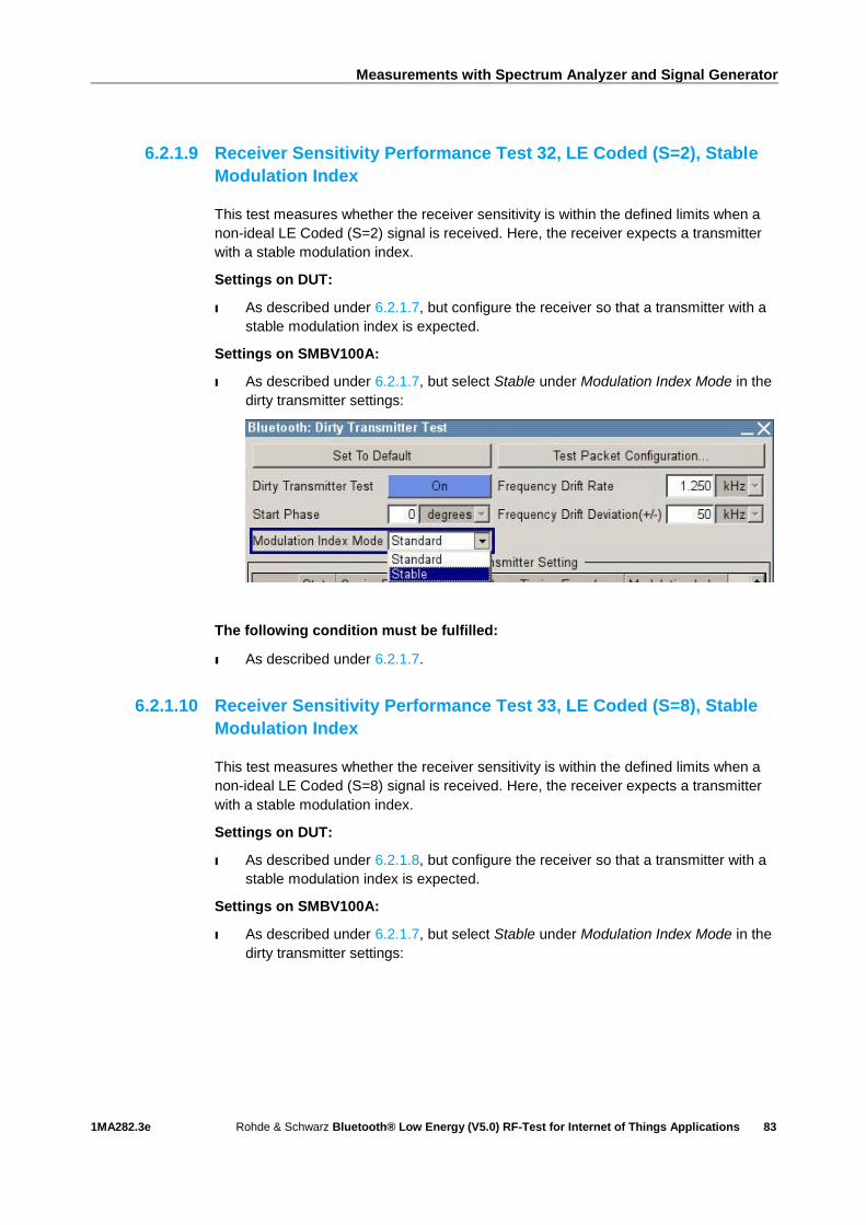
Measurements with Spectrum Analyzer and Signal Generator
1MA282.3e Rohde & Schwarz Bluetooth® Low Energy (V5.0) RF-Test for Internet of Things Applications
83
6.2.1.9 Receiver Sensitivity Performance Test 32, LE Coded (S=2), Stable
Modulation Index
This test measures whether the receiver sensitivity is within the defined limits when a
non-ideal LE Coded (S=2) signal is received. Here, the receiver expects a transmitter
with a stable modulation index.
Settings on DUT:
I As described under 6.2.1.7, but configure the receiver so that a transmitter with a
stable modulation index is expected.
Settings on SMBV100A:
I As described under 6.2.1.7, but select Stable under Modulation Index Mode in the
dirty transmitter settings:
The following condition must be fulfilled:
ı As described under 6.2.1.7.
6.2.1.10 Receiver Sensitivity Performance Test 33, LE Coded (S=8), Stable
Modulation Index
This test measures whether the receiver sensitivity is within the defined limits when a
non-ideal LE Coded (S=8) signal is received. Here, the receiver expects a transmitter
with a stable modulation index.
Settings on DUT:
I As described under 6.2.1.8, but configure the receiver so that a transmitter with a
stable modulation index is expected.
Settings on SMBV100A:
I As described under 6.2.1.7, but select Stable under Modulation Index Mode in the
dirty transmitter settings:
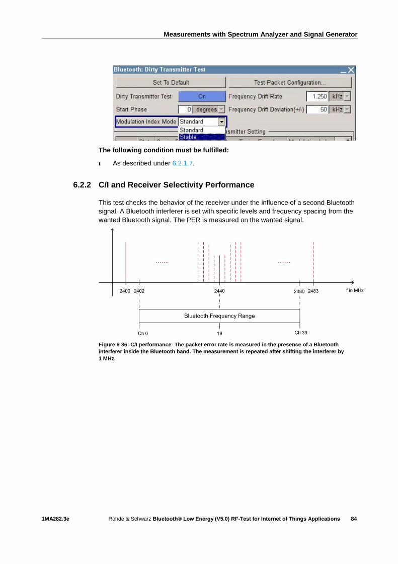
Measurements with Spectrum Analyzer and Signal Generator
1MA282.3e Rohde & Schwarz Bluetooth® Low Energy (V5.0) RF-Test for Internet of Things Applications
84
The following condition must be fulfilled:
ı As described under 6.2.1.7.
6.2.2 C/I and Receiver Selectivity Performance
This test checks the behavior of the receiver under the influence of a second Bluetooth
signal. A Bluetooth interferer is set with specific levels and frequency spacing from the
wanted Bluetooth signal. The PER is measured on the wanted signal.
Figure 6-36: C/I performance: The packet error rate is measured in the presence of a Bluetooth
interferer inside the Bluetooth band. The measurement is repeated after shifting the interferer by
1 MHz.
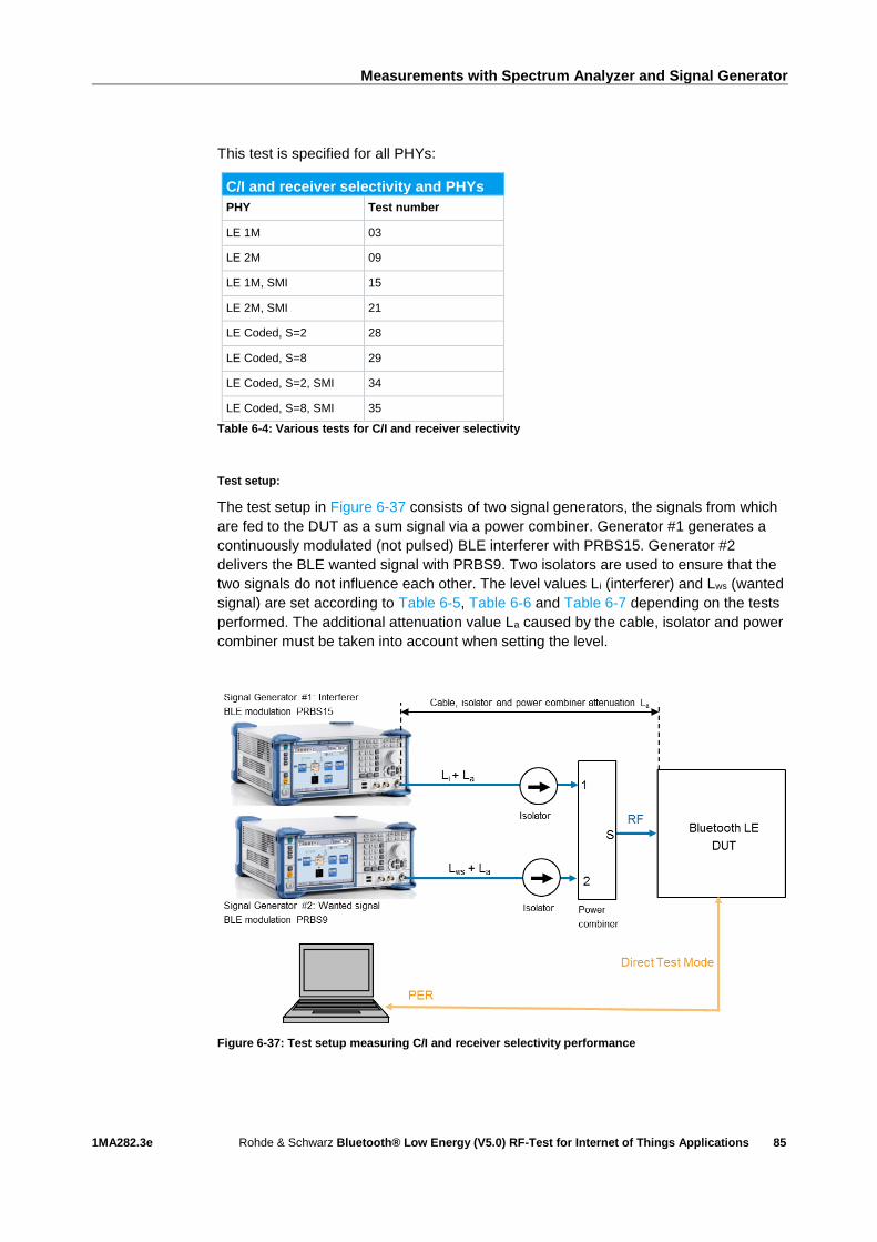
Measurements with Spectrum Analyzer and Signal Generator
1MA282.3e Rohde & Schwarz Bluetooth® Low Energy (V5.0) RF-Test for Internet of Things Applications
85
This test is specified for all PHYs:
C/I and receiver selectivity and PHYs
PHY Test number
LE 1M 03
LE 2M 09
LE 1M, SMI 15
LE 2M, SMI 21
LE Coded, S=2 28
LE Coded, S=8 29
LE Coded, S=2, SMI 34
LE Coded, S=8, SMI 35
Table 6-4: Various tests for C/I and receiver selectivity
Test setup:
The test setup in Figure 6-37 consists of two signal generators, the signals from which
are fed to the DUT as a sum signal via a power combiner. Generator #1 generates a
continuously modulated (not pulsed) BLE interferer with PRBS15. Generator #2
delivers the BLE wanted signal with PRBS9. Two isolators are used to ensure that the
two signals do not influence each other. The level values Li (interferer) and Lws (wanted
signal) are set according to Table 6-5, Table 6-6 and Table 6-7 depending on the tests
performed. The additional attenuation value La caused by the cable, isolator and power
combiner must be taken into account when setting the level.
Figure 6-37: Test setup measuring C/I and receiver selectivity performance

Measurements with Spectrum Analyzer and Signal Generator
1MA282.3e Rohde & Schwarz Bluetooth® Low Energy (V5.0) RF-Test for Internet of Things Applications
86
C/I LE level settings for tests 03, 09, 15, 21
Interference signal frequency Interferer (abs), Li
C/I Wanted signal (abs), Lws
Co-channel
(f RX = f Interference)
–88 dBm 21 dB –67 dBm
Adjacent channel
(f Interference = f RX ±1 MHz)
–82 dBm 15 dB –67 dBm
Adjacent channel
(f Interference = f RX ±2 MHz)
–50 dBm –17 dB –67 dBm
Adjacent channel
(f Interference = f RX ±(3 + n) MHz)
n = 0, 1, 2, 3… (2400 MHz ≤ f Interference ≤ 2483 MHz)
–40 dBm –27 dB –67 dBm
Image frequency
(f Interference = f Image)
–58 dBm –9 dB –67 dBm
Adjacent channel to image frequency
(f Interference = f Image ±1 MHz)
–52 dBm –15 dB –67 dBm
Table 6-5: C/I and receiver selectivity test parameter settings
C/I LE level settings for tests 28, 34
Interference signal frequency Interferer (abs), Li
C/I
Wanted signal (abs), Lws
Co-channel
(f RX = f Interference)
‒89 dBm 17 dB –72 dBm
Adjacent channel
(f Interference = f RX ±1 MHz)
–83 dBm 11 dB –72 dBm
Adjacent channel
(f Interference = f RX ±2 MHz)
–51 dBm ‒21 dB –72 dBm
Adjacent channel
(f Interference = f RX ±(3 + n) MHz)
n = 0, 1, 2, 3… (2400 MHz ≤ f Interference ≤ 2483 MHz)
–41 dBm ‒31 dB –72 dBm
Image frequency
(f Interference = f Image)
–59 dBm –13 dB –72 dBm
Adjacent channel to image frequency
(f Interference = f Image ±1 MHz)
–53 dBm –19 dB –72 dBm
Table 6-6: C/I and receiver selectivity test parameter settings for LE Coded S=2

Measurements with Spectrum Analyzer and Signal Generator
1MA282.3e Rohde & Schwarz Bluetooth® Low Energy (V5.0) RF-Test for Internet of Things Applications
87
C/I LE level settings for tests 29, 35
Interference signal frequency Interferer (abs), Li
C/I Wanted signal (abs), Lws
Co-channel
(f RX = f Interference)
–91 dBm 12 dB –79 dBm
Adjacent channel
(f Interference = f RX ±1 MHz)
–85 dBm 6 dB –79 dBm
Adjacent channel
(f Interference = f RX ±2 MHz)
–53 dBm –26 dB –79 dBm
Adjacent channel
(f Interference = f RX ±(3 + n) MHz)
n = 0, 1, 2, 3… (2400 MHz ≤ f Interference ≤ 2483 MHz)
–43 dBm –36 dB –79 dBm
Image frequency
(f Interference = f Image)
–61 dBm –18 dB –79 dBm
Adjacent channel to image frequency
(f Interference = f Image ±1 MHz)
–55 dBm –24 dB –79 dBm
Table 6-7: C/I and receiver selectivity test parameter settings for LE Coded S=8
6.2.2.1 C/I and Receiver Selectivity Performance Test 03, Uncoded Data at
1 Ms/s
This test checks the behavior of a BLE receiver in the presence of a Bluetooth
interferer with uncoded data and a 1 Ms/s data rate. The interferer is transmitted on the
receive frequency or in the adjacent channel. The image frequency suppression of the
receiver is also tested.
Settings on DUT:
1. Switch on Direct RX mode. Switch off dewhitening.
2. Switch off frequency hopping.
3. Set the symbol rate to 1 Ms/s.
4. Configure the receiver so that a transmitter with a standard modulation index is
expected.
5. Set the receive frequency.
Tables 6.1 and 6.2 in 6.2 Frequencies for Testing of the Bluetooth test
specification specify the DUT's transmit and receive frequencies for the different
test cases and device types. The C/I and receiver selectivity performance test is
performed for all three RX frequencies: fRX (low), fRX (middle) and fRX (highest).
Settings on signal generator #2 (SMBV100A): wanted signal
6. Press the PRESET key.
7. Press the MENU key and select Bluetooth from the list:

Measurements with Spectrum Analyzer and Signal Generator
1MA282.3e Rohde & Schwarz Bluetooth® Low Energy (V5.0) RF-Test for Internet of Things Applications
88
8. Configure the settings as shown in Figure 6-38. The Sequence Length must be at
least 1500.
Figure 6-38: Generator settings for the wanted signal
9. In the Bluetooth window (Figure 6-38), scroll down with the arrow key and
select Test Packet Configuration…:
10. Make sure that PRBS9 is selected as the payload type. If the DUT supports the
"Extended Packet Length" feature (in line with core specification 4.2), then
Payload Length must be set to the maximum possible packet length supported
by the DUT. If "Extended Packet Length" is not supported, Payload Length must
be set to 37 bytes:

Measurements with Spectrum Analyzer and Signal Generator
1MA282.3e Rohde & Schwarz Bluetooth® Low Energy (V5.0) RF-Test for Internet of Things Applications
89
Figure 6-39: Test packet configuration
11. Close the "Test Packet Configuration" window.
12. Press the FREQ key and, for the first test run, enter the frequency value for fRX
(low) as described under 6.2 Frequencies for Testing in the test specification. For
the second and third test runs, enter fRX (middle) and fRX (highest).
13. Press the LEVEL key and enter the value ‒67 dBm + La (see also Table 6-5 and
Figure 6-37).
14. Start the calculation of the Bluetooth test signal with State = On. After the
calculation, press the RF ON/OFF key to switch on the Bluetooth RF signal.
Settings on signal generator #1 (SMBV100A): interferer
15. Press the PRESET key.
16. Press the MENU key and select Bluetooth from the list:
17. Configure the settings as shown in Figure 6-40.

Measurements with Spectrum Analyzer and Signal Generator
1MA282.3e Rohde & Schwarz Bluetooth® Low Energy (V5.0) RF-Test for Internet of Things Applications
90
Figure 6-40: Generator settings for the interferer
18. Start the calculation of the Bluetooth test signal with State = On. After the
calculation, press the RF ON/OFF key to switch on the Bluetooth RF signal.
19. finterfer = 2400 MHz.
20. Use the FREQ key and LEVEL key to enter the frequency and level values
specified in Table 6-5 one after the other and determine the associated PER. (See
also TIP below.)
Note: The manufacturer of the BLE receiver specifies fImage in Table 6-5 for the
currently used symbol rate.
The following conditions apply:
ı PER < 30.8 % (for Payload Length = 37 bytes and at least 1500 packets). For
other payload lengths, the PER limit is given in Table 6.4: PER level by maximum
payload length in receiver of the test specification.
In the case of signal-to-interference ratios ≥ ±2 MHz in the 2400 MHz to
2483 MHz frequency band, the specified PER limit is allowed to be exceeded five
times. Record the frequencies for these values. If more than five frequencies fail
to fulfill this condition, the DUT has not passed the test and the test can be
terminated immediately. For all recorded frequencies (≤ 5), repeat the test as
follows:
21. On signal generator #1, set the level of the interferer to ‒50 dBm + La
(corresponds to C/I = ‒17 dB).
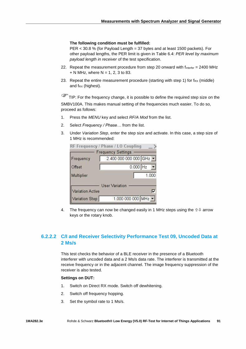
Measurements with Spectrum Analyzer and Signal Generator
1MA282.3e Rohde & Schwarz Bluetooth® Low Energy (V5.0) RF-Test for Internet of Things Applications
91
The following condition must be fulfilled:
PER < 30.8 % (for Payload Length = 37 bytes and at least 1500 packets). For
other payload lengths, the PER limit is given in Table 6.4: PER level by maximum
payload length in receiver of the test specification.
22. Repeat the measurement procedure from step 20 onward with finterfer = 2400 MHz
+ N MHz, where N = 1, 2, 3 to 83.
23. Repeat the entire measurement procedure (starting with step 1) for fRX (middle)
and fRX (highest).
TIP: For the frequency change, it is possible to define the required step size on the
SMBV100A. This makes manual setting of the frequencies much easier. To do so,
proceed as follows:
1. Press the MENU key and select RF/A Mod from the list.
2. Select Frequency / Phase… from the list.
3. Under Variation Step, enter the step size and activate. In this case, a step size of
1 MHz is recommended:
4. The frequency can now be changed easily in 1 MHz steps using the arrow
keys or the rotary knob.
6.2.2.2 C/I and Receiver Selectivity Performance Test 09, Uncoded Data at
2 Ms/s
This test checks the behavior of a BLE receiver in the presence of a Bluetooth
interferer with uncoded data and a 2 Ms/s data rate. The interferer is transmitted at the
receive frequency or in the adjacent channel. The image frequency suppression of the
receiver is also tested.
Settings on DUT:
1. Switch on Direct RX mode. Switch off dewhitening.
2. Switch off frequency hopping.
3. Set the symbol rate to 1 Ms/s.
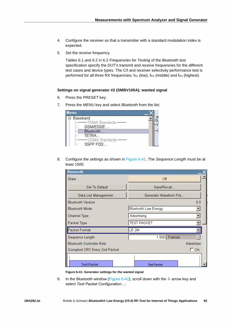
Measurements with Spectrum Analyzer and Signal Generator
1MA282.3e Rohde & Schwarz Bluetooth® Low Energy (V5.0) RF-Test for Internet of Things Applications
92
4. Configure the receiver so that a transmitter with a standard modulation index is
expected.
5. Set the receive frequency.
Tables 6.1 and 6.2 in 6.2 Frequencies for Testing of the Bluetooth test
specification specify the DUT's transmit and receive frequencies for the different
test cases and device types. The C/I and receiver selectivity performance test is
performed for all three RX frequencies: fRX (low), fRX (middle) and fRX (highest).
Settings on signal generator #2 (SMBV100A): wanted signal
6. Press the PRESET key.
7. Press the MENU key and select Bluetooth from the list:
8. Configure the settings as shown in Figure 6-41. The Sequence Length must be at
least 1500.
Figure 6-41: Generator settings for the wanted signal
9. In the Bluetooth window (Figure 6-41), scroll down with the arrow key and
select Test Packet Configuration…:

Measurements with Spectrum Analyzer and Signal Generator
1MA282.3e Rohde & Schwarz Bluetooth® Low Energy (V5.0) RF-Test for Internet of Things Applications
93
10. Make sure that PRBS9 is selected as the payload type. If the DUT supports the
"Extended Packet Length" feature (in line with core specification 4.2), then
Payload Length must be set to the maximum possible packet length supported
by the DUT. If "Extended Packet Length" is not supported, Payload Length must
be set to 37 bytes:
Figure 6-42: Test packet configuration
11. Close the "Test Packet Configuration" window.
12. Press the FREQ key and, for the first test run, enter the frequency value for fRX
(low) as describes desd under 6.2 Frequencies for Testing in the test
specification. For the second and third test runs, enter fRX (middle) and
fRX (highest).
13. Press the LEVEL key and enter the value ‒67 dBm + La (see also Table 6-5 and
Figure 6-37).
14. Start the calculation of the Bluetooth test signal with State = On. After the
calculation, press the RF ON/OFF key to switch on the Bluetooth RF signal.
Settings on signal generator #1 (SMBV100A): interferer
15. Press the PRESET key.
16. Press the MENU key and select Bluetooth from the list:

Measurements with Spectrum Analyzer and Signal Generator
1MA282.3e Rohde & Schwarz Bluetooth® Low Energy (V5.0) RF-Test for Internet of Things Applications
94
17. Configure the settings as shown in Figure 6-44.
Figure 6-43: Generator settings for the interferer
18. Start the calculation of the Bluetooth test signal with State = On. After the
calculation, press the RF ON/OFF key to switch on the Bluetooth RF signal.
19. finterfer = 2400 MHz.
20. Use the FREQ key and LEVEL key to enter the frequency and level values
specified in Table 6-5 one after the other and determine the associated PER. (See
also TIP below.)
Note: The manufacturer of the BLE receiver specifies fImage in Table 6-5 for the
currently used symbol rate.
The following conditions apply:
I PER < 30.8 % (for Payload Length = 37 bytes and at least 1500 packets). For other
payload lengths, the PER limit is given in Table 6.4: PER level by maximum
payload length in receiver of the test specification.
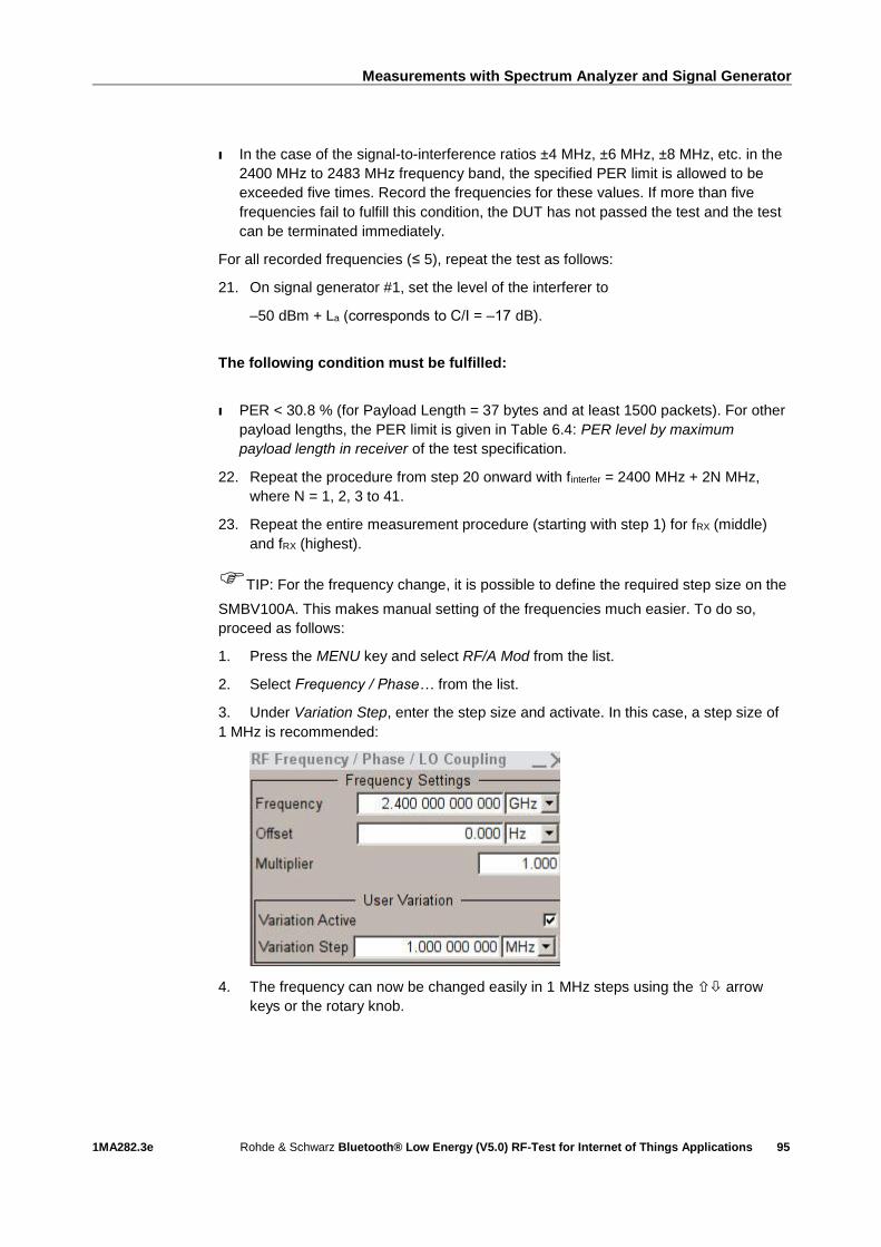
Measurements with Spectrum Analyzer and Signal Generator
1MA282.3e Rohde & Schwarz Bluetooth® Low Energy (V5.0) RF-Test for Internet of Things Applications
95
I In the case of the signal-to-interference ratios ±4 MHz, ±6 MHz, ±8 MHz, etc. in the
2400 MHz to 2483 MHz frequency band, the specified PER limit is allowed to be
exceeded five times. Record the frequencies for these values. If more than five
frequencies fail to fulfill this condition, the DUT has not passed the test and the test
can be terminated immediately.
For all recorded frequencies (≤ 5), repeat the test as follows:
21. On signal generator #1, set the level of the interferer to
‒50 dBm + La (corresponds to C/I = ‒17 dB).
The following condition must be fulfilled:
I PER < 30.8 % (for Payload Length = 37 bytes and at least 1500 packets). For other
payload lengths, the PER limit is given in Table 6.4: PER level by maximum
payload length in receiver of the test specification.
22. Repeat the procedure from step 20 onward with finterfer = 2400 MHz + 2N MHz,
where N = 1, 2, 3 to 41.
23. Repeat the entire measurement procedure (starting with step 1) for fRX (middle)
and fRX (highest).
TIP: For the frequency change, it is possible to define the required step size on the
SMBV100A. This makes manual setting of the frequencies much easier. To do so,
proceed as follows:
1. Press the MENU key and select RF/A Mod from the list.
2. Select Frequency / Phase… from the list.
3. Under Variation Step, enter the step size and activate. In this case, a step size of
1 MHz is recommended:
4. The frequency can now be changed easily in 1 MHz steps using the arrow
keys or the rotary knob.

Measurements with Spectrum Analyzer and Signal Generator
1MA282.3e Rohde & Schwarz Bluetooth® Low Energy (V5.0) RF-Test for Internet of Things Applications
96
6.2.2.3 C/I and Receiver Sensitivity Performance Test 15, Uncoded Data at
1 Ms/s, Stable Modulation Index
This test checks the behavior of a BLE receiver in the presence of a Bluetooth
interferer with uncoded data and a 1 Ms/s data rate. Here, the receiver expects a
transmitter with a stable modulation index. The interferer is transmitted at the receive
frequency or in the adjacent channel. The image frequency suppression of the receiver
is also tested.
Settings on DUT:
I As described under 6.2.2.1, but configure the DUT so that a transmitter with a
stable modulation index is expected.
Settings on signal generator #2 (SMBV100A): wanted signal
I As described under 6.2.2.1.
Settings on signal generator #1 (SMBV100A): interferer
I As described under 6.2.2.1.
6.2.2.4 C/I and Receiver Sensitivity Performance Test 21, Uncoded Data at
2 Ms/s, Stable Modulation Index
This test checks the behavior of a BLE receiver in the presence of a Bluetooth
interferer with uncoded data and a 2 Ms/s data rate. Here, the receiver expects a
transmitter with a stable modulation index. The interferer is transmitted at the receive
frequency or in the adjacent channel. The image frequency suppression of the receiver
is also tested.
Settings on DUT:
I As described under 6.2.2.2, but configure the DUT so that a transmitter with a
stable modulation index is expected.
Settings on signal generator #2 (SMBV100A): wanted signal
I As described under 6.2.2.2.
Settings on signal generator #1 (SMBV100A): interferer
I As described under 6.2.2.2.
6.2.2.5 C/I and Receiver Selectivity Performance Test 28, LE Coded (S=2)
This test checks the behavior of a BLE receiver in the presence of a Bluetooth
interferer when an LE Coded signal with S=2 is received. The interferer is transmitted

Measurements with Spectrum Analyzer and Signal Generator
1MA282.3e Rohde & Schwarz Bluetooth® Low Energy (V5.0) RF-Test for Internet of Things Applications
97
at the receive frequency or in the adjacent channel. The image frequency suppression
of the receiver is also tested.
Settings on DUT:
1. Switch on Direct RX mode. Switch off dewhitening.
2. Switch off frequency hopping.
3. Configure to receive LE Coded PHY with data coding S=2 and a bit rate of
500 kB/s.
4. Configure the receiver so that a transmitter with a standard modulation index is
expected.
5. Set the receive frequency.
Tables 6.1 and 6.2 in 6.2 Frequencies for Testing of the Bluetooth test
specification specify the DUT's transmit and receive frequencies for the different
test cases and device types. The C/I and receiver selectivity performance test is
performed for all three RX frequencies: fRX (low), fRX (middle) and fRX (highest).
Settings on signal generator #2 (SMBV100A): wanted signal
6. Press the PRESET key.
7. Press the MENU key and select Bluetooth from the list:
8. Configure the settings as shown in Figure 6-44. The Sequence Length must be at
least 1500.

Measurements with Spectrum Analyzer and Signal Generator
1MA282.3e Rohde & Schwarz Bluetooth® Low Energy (V5.0) RF-Test for Internet of Things Applications
98
Figure 6-44: Generator settings for the wanted signal
9. In the Bluetooth window (Figure 6-44), scroll down with the arrow key and
select Test Packet Configuration…:
10. Set Symbols per a Bit to 2 and make sure that PRBS9 is selected as the payload
type. If the DUT supports the "Extended Packet Length" feature (in line with core
specification 4.2), then Payload Length must be set to the maximum possible
packet length supported by the DUT. If "Extended Packet Length" is not
supported, Payload Length must be set to 37 bytes:
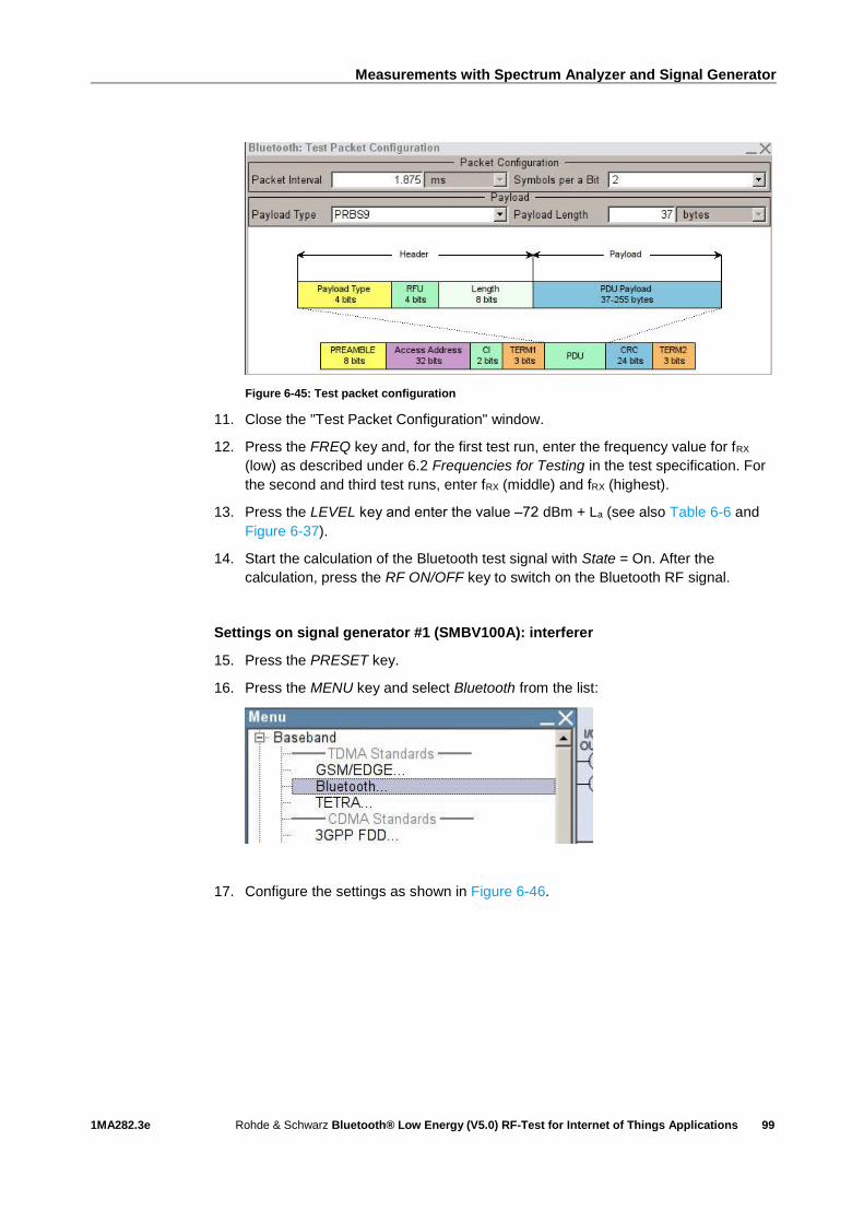
Measurements with Spectrum Analyzer and Signal Generator
1MA282.3e Rohde & Schwarz Bluetooth® Low Energy (V5.0) RF-Test for Internet of Things Applications
99
Figure 6-45: Test packet configuration
11. Close the "Test Packet Configuration" window.
12. Press the FREQ key and, for the first test run, enter the frequency value for fRX
(low) as described under 6.2 Frequencies for Testing in the test specification. For
the second and third test runs, enter fRX (middle) and fRX (highest).
13. Press the LEVEL key and enter the value ‒72 dBm + La (see also Table 6-6 and
Figure 6-37).
14. Start the calculation of the Bluetooth test signal with State = On. After the
calculation, press the RF ON/OFF key to switch on the Bluetooth RF signal.
Settings on signal generator #1 (SMBV100A): interferer
15. Press the PRESET key.
16. Press the MENU key and select Bluetooth from the list:
17. Configure the settings as shown in Figure 6-46.
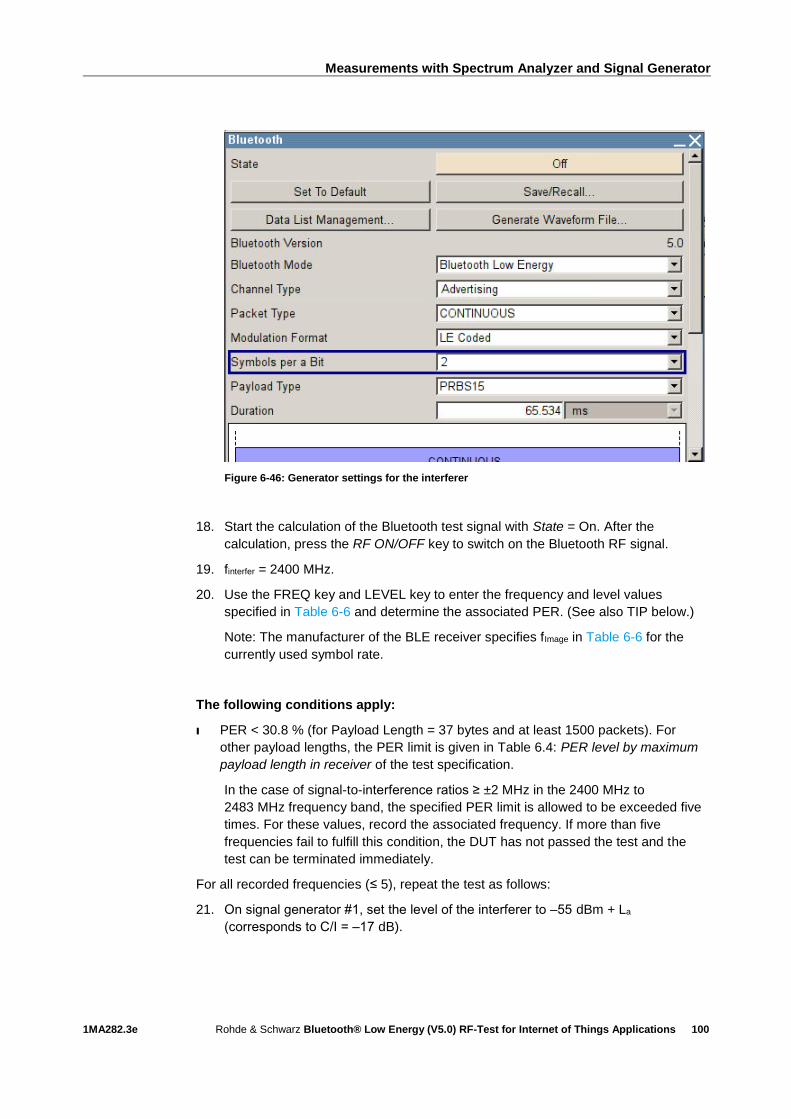
Measurements with Spectrum Analyzer and Signal Generator
1MA282.3e Rohde & Schwarz Bluetooth® Low Energy (V5.0) RF-Test for Internet of Things Applications
100
Figure 6-46: Generator settings for the interferer
18. Start the calculation of the Bluetooth test signal with State = On. After the
calculation, press the RF ON/OFF key to switch on the Bluetooth RF signal.
19. finterfer = 2400 MHz.
20. Use the FREQ key and LEVEL key to enter the frequency and level values
specified in Table 6-6 and determine the associated PER. (See also TIP below.)
Note: The manufacturer of the BLE receiver specifies fImage in Table 6-6 for the
currently used symbol rate.
The following conditions apply:
I PER < 30.8 % (for Payload Length = 37 bytes and at least 1500 packets). For
other payload lengths, the PER limit is given in Table 6.4: PER level by maximum
payload length in receiver of the test specification.
In the case of signal-to-interference ratios ≥ ±2 MHz in the 2400 MHz to
2483 MHz frequency band, the specified PER limit is allowed to be exceeded five
times. For these values, record the associated frequency. If more than five
frequencies fail to fulfill this condition, the DUT has not passed the test and the
test can be terminated immediately.
For all recorded frequencies (≤ 5), repeat the test as follows:
21. On signal generator #1, set the level of the interferer to ‒55 dBm + La
(corresponds to C/I = ‒17 dB).

Measurements with Spectrum Analyzer and Signal Generator
1MA282.3e Rohde & Schwarz Bluetooth® Low Energy (V5.0) RF-Test for Internet of Things Applications
101
The following condition must be fulfilled:
I PER < 30.8 % (for Payload Length = 37 bytes and at least 1500 packets). For
other payload lengths, the PER limit is given in Table 6.4: PER level by maximum
payload length in receiver of the test specification.
22. Repeat the procedure from step 20 onward with finterfer = 2400 MHz + N MHz,
where N = 1, 2, 3 to 83.
23. Repeat the entire measurement procedure (starting with step 1) for fRX (middle)
and fRX (highest).
TIP: For the frequency change, it is possible to define the required step size on the
SMBV100A. This makes manual setting of the frequencies much easier. To do so,
proceed as follows:
1. Press the MENU key and select RF/A Mod from the list.
2. Select Frequency / Phase… from the list.
3. Under Variation Step, enter the step size and activate. In this case, a step size of
1 MHz is recommended:
4. The frequency can now be changed easily in 1 MHz steps using the arrow
keys or the rotary knob.
6.2.2.6 C/I and Receiver Selectivity Performance Test 29, LE Coded (S=8)
This test checks the behavior of a BLE receiver in the presence of a Bluetooth
interferer when an LE Coded signal with S=8 is received. The interferer is transmitted
at the receive frequency or in the adjacent channel. The image frequency suppression
of the receiver is also tested.
Settings on DUT:
1. Switch on Direct RX mode. Switch off dewhitening.
2. Switch off frequency hopping.
3. Configure to receive LE Coded PHY with data coding S=8 and a bit rate of
125 kB/s.
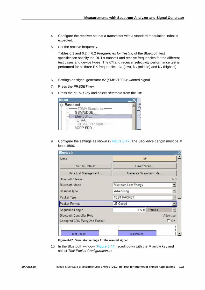
Measurements with Spectrum Analyzer and Signal Generator
1MA282.3e Rohde & Schwarz Bluetooth® Low Energy (V5.0) RF-Test for Internet of Things Applications
102
4. Configure the receiver so that a transmitter with a standard modulation index is
expected.
5. Set the receive frequency.
Tables 6.1 and 6.2 in 6.2 Frequencies for Testing of the Bluetooth test
specification specify the DUT's transmit and receive frequencies for the different
test cases and device types. The C/I and receiver selectivity performance test is
performed for all three RX frequencies: fRX (low), fRX (middle) and fRX (highest).
6. Settings on signal generator #2 (SMBV100A): wanted signal
7. Press the PRESET key.
8. Press the MENU key and select Bluetooth from the list:
9. Configure the settings as shown in Figure 6-47. The Sequence Length must be at
least 1500.
Figure 6-47: Generator settings for the wanted signal
10. In the Bluetooth window (Figure 6-44), scroll down with the arrow key and
select Test Packet Configuration…:

Measurements with Spectrum Analyzer and Signal Generator
1MA282.3e Rohde & Schwarz Bluetooth® Low Energy (V5.0) RF-Test for Internet of Things Applications
103
11. Set Symbols per a Bit to 8 and make sure that PRBS9 is selected as the payload
type. If the DUT supports the "Extended Packet Length" feature (in line with core
specification 4.2), then Payload Length must be set to the maximum possible
packet length supported by the DUT. If "Extended Packet Length" is not
supported, Payload Length must be set to 37 bytes:
Figure 6-48: Test packet configuration
12. Close the "Test Packet Configuration" window.
13. Press the FREQ key and, for the first test run, enter the frequency value for fRX
(low) as described under 6.2 Frequencies for Testing in the test specification. For
the second and third test runs, enter fRX (middle) and fRX (highest).
14. Press the LEVEL key and enter the value ‒79 dBm + La (see also Table 6-7 and
Figure 6-37).
15. Start the calculation of the Bluetooth test signal with State = On. After the
calculation, press the RF ON/OFF key to switch on the Bluetooth RF signal.
Settings on signal generator #1 (SMBV100A): interferer
16. Press the PRESET key.
17. Press the MENU key and select Bluetooth from the list:
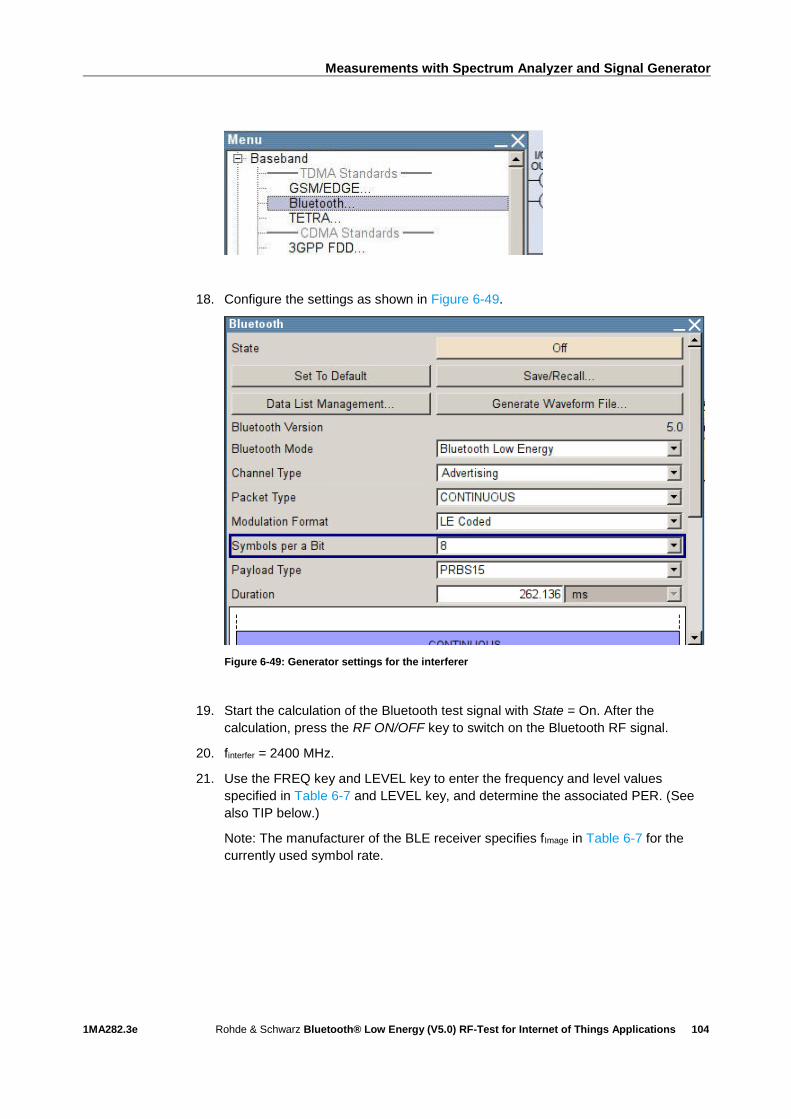
Measurements with Spectrum Analyzer and Signal Generator
1MA282.3e Rohde & Schwarz Bluetooth® Low Energy (V5.0) RF-Test for Internet of Things Applications
104
18. Configure the settings as shown in Figure 6-49.
Figure 6-49: Generator settings for the interferer
19. Start the calculation of the Bluetooth test signal with State = On. After the
calculation, press the RF ON/OFF key to switch on the Bluetooth RF signal.
20. finterfer = 2400 MHz.
21. Use the FREQ key and LEVEL key to enter the frequency and level values
specified in Table 6-7 and LEVEL key, and determine the associated PER. (See
also TIP below.)
Note: The manufacturer of the BLE receiver specifies fImage in Table 6-7 for the
currently used symbol rate.

Measurements with Spectrum Analyzer and Signal Generator
1MA282.3e Rohde & Schwarz Bluetooth® Low Energy (V5.0) RF-Test for Internet of Things Applications
105
The following conditions apply:
I PER < 30.8 % (for Payload Length = 37 bytes and at least 1500 packets). For
other payload lengths, the PER limit is given in Table 6.4: PER level by maximum
payload length in receiver of the test specification.
In the case of signal-to-interference ratios ≥ ±2 MHz in the 2400 MHz to
2483 MHz frequency band, the specified PER limit is allowed to be exceeded five
times. For these values, record the associated frequency. If more than five
frequencies fail to fulfill this condition, the DUT has not passed the test and the
test can be terminated immediately.
For all recorded frequencies (≤ 5), repeat the test as follows:
22. On signal generator #1, set the level of the interferer to ‒62 dBm + La
(corresponds to C/I = ‒17 dB).
The following condition must be fulfilled:
I PER < 30.8 % (for Payload Length = 37 bytes and at least 1500 packets). For
other payload lengths, the PER limit is given in Table 6.4: PER level by maximum
payload length in receiver of the test specification.
23. Repeat the procedure from step 22 onward with finterfer = 2400 MHz + N MHz,
where N = 1, 2, 3 to 83.
24. Repeat the entire measurement procedure (starting with step 1) for fRX (middle)
and fRX (highest).
TIP: For the frequency change, it is possible to define the required step size on the
SMBV100A. This makes manual setting of the frequencies much easier. To do so,
proceed as follows:
1. Press the MENU key and select RF/A Mod from the list.
2. Select Frequency / Phase… from the list.
3. Under Variation Step, enter the step size and activate. In this case, a step size of
1 MHz is recommended:
4. The frequency can now be changed easily in 1 MHz steps using the arrow
keys or the rotary knob.
Measurements with Spectrum Analyzer and Signal Generator
1MA282.3e Rohde & Schwarz Bluetooth® Low Energy (V5.0) RF-Test for Internet of Things Applications
106
6.2.2.7 C/I and Receiver Selectivity Performance Test 34, LE Coded (S=2),
Stable Modulation Index
This test checks the behavior of a BLE receiver in the presence of a Bluetooth
interferer when an LE Coded signal with S=2 is received. Here, the receiver expects a
transmitter with a stable modulation index. The interferer is transmitted at the receive
frequency or in the adjacent channel. The image frequency suppression of the receiver
is also tested.
Settings on DUT:
I As described in 6.2.2.5, but configure the receiver so that a transmitter with a
stable modulation index is expected.
Settings on signal generator #2 (SMBV100A): wanted signal
I As described in 6.2.2.5.
Settings on signal generator #1 (SMBV100A): interferer
I As described in 6.2.2.5.
6.2.2.8 C/I and Receiver Selectivity Performance Test 34, LE Coded (S=8),
Stable Modulation Index
This test checks the behavior of a BLE receiver in the presence of a Bluetooth
interferer when an LE Coded signal with S=8 is received. Here, the receiver expects a
transmitter with a stable modulation index. The interferer is transmitted at the receive
frequency or in the adjacent channel. The image frequency suppression of the receiver
is also tested.
Settings on DUT:
I As described in 6.2.2.6, but configure the receiver so that a transmitter with a
stable modulation index is expected.
Settings on signal generator #2 (SMBV100A): wanted signal
I As described in 6.2.2.6.
Settings on signal generator #1 (SMBV100A): interferer
I As described in 6.2.2.6.
6.2.3 Blocking Performance
This test checks the behavior of the receiver under the influence of a non-Bluetooth
signal. The interferer is an unmodulated signal (CW) and moves outside the Bluetooth
frequency band (2400 MHz to 2483 MHz) with different frequency steps (frequency
resolution). An interferer is set with specific levels and frequency spacing from the
wanted Bluetooth signal. The PER is measured on the wanted signal. (Figure 6-50).
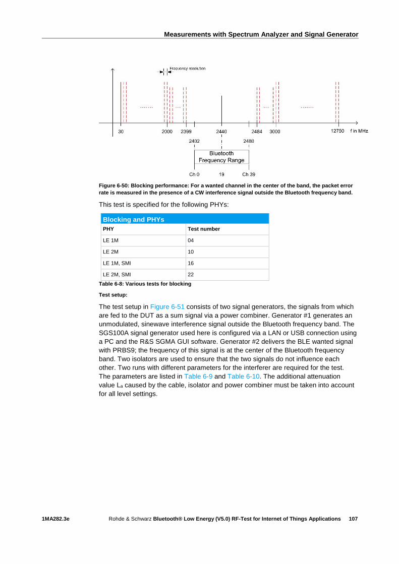
Measurements with Spectrum Analyzer and Signal Generator
1MA282.3e Rohde & Schwarz Bluetooth® Low Energy (V5.0) RF-Test for Internet of Things Applications
107
Figure 6-50: Blocking performance: For a wanted channel in the center of the band, the packet error
rate is measured in the presence of a CW interference signal outside the Bluetooth frequency band.
This test is specified for the following PHYs:
Blocking and PHYs
PHY Test number
LE 1M 04
LE 2M 10
LE 1M, SMI 16
LE 2M, SMI 22
Table 6-8: Various tests for blocking
Test setup:
The test setup in Figure 6-51 consists of two signal generators, the signals from which
are fed to the DUT as a sum signal via a power combiner. Generator #1 generates an
unmodulated, sinewave interference signal outside the Bluetooth frequency band. The
SGS100A signal generator used here is configured via a LAN or USB connection using
a PC and the R&S SGMA GUI software. Generator #2 delivers the BLE wanted signal
with PRBS9; the frequency of this signal is at the center of the Bluetooth frequency
band. Two isolators are used to ensure that the two signals do not influence each
other. Two runs with different parameters for the interferer are required for the test.
The parameters are listed in Table 6-9 and Table 6-10. The additional attenuation
value La caused by the cable, isolator and power combiner must be taken into account
for all level settings.

Measurements with Spectrum Analyzer and Signal Generator
1MA282.3e Rohde & Schwarz Bluetooth® Low Energy (V5.0) RF-Test for Internet of Things Applications
108
Figure 6-51: Test setup for blocking performance measurement
Blocking settings
Interference signal frequency, fi
Wanted signal level, Lws Blocking signal level, Lb Frequency resolution, fres
30 MHz to 2000 MHz –67 dBm –30 dBm 10 MHz
2003 MHz to 2399 MHz –67 dBm –35 dBm 3 MHz
2484 MHz to 2997 MHz –67 dBm –35 dBm 3 MHz
3000 MHz to 12.75 GHz –67 dBm –30 dBm 25 MHz
Table 6-9: Blocking performance parameters – 1st test run
Blocking settings
Interference signal frequency, fi
Wanted signal level, Lws Blocking signal level, Lb Frequency resolution, fres
30 MHz to 2000 MHz –67 dBm –50 dBm 10 MHz
2003 MHz to 2399 MHz –67 dBm –50 dBm 3 MHz
2484 MHz to 2997 MHz –67 dBm –50 dBm 3 MHz
3000 MHz to 12.75 GHz –67 dBm –50 dBm 25 MHz
Table 6-10: Blocking performance parameters – 2nd test run
6.2.3.1 Blocking Performance Test 04 (LE 1M, Uncoded Data at 1 Ms/s)
This test checks whether a BLE receiver operates satisfactorily in the presence of a
CW interferer outside the Bluetooth frequency band when uncoded data with a symbol
rate of 1 Ms/s is received.
Settings on DUT:
1. Switch on Direct RX mode. Switch off dewhitening.
2. Switch off frequency hopping.
3. Set the symbol rate to 1 Ms/s.

Measurements with Spectrum Analyzer and Signal Generator
1MA282.3e Rohde & Schwarz Bluetooth® Low Energy (V5.0) RF-Test for Internet of Things Applications
109
4. Configure the DUT so that a transmitter with a standard modulation index is
expected.
5. Settings on SMBV100A #2 (wanted signal):
6. Press the PRESET key.
7. Press the MENU key and select Bluetooth from the list:
8. Configure the settings as shown in Figure 6-52. The Sequence Length must be at
least 1500.
Figure 6-52: Generator settings for Maximum Input Level Test 04
9. In the Bluetooth window (Figure 6-52), scroll down with the arrow key and
select Test Packet Configuration…:

Measurements with Spectrum Analyzer and Signal Generator
1MA282.3e Rohde & Schwarz Bluetooth® Low Energy (V5.0) RF-Test for Internet of Things Applications
110
10. Make sure that PRBS9 is selected as the payload type. If the DUT supports the
"Extended Packet Length" feature (in line with core specification 4.2), then
Payload Length must be set to the maximum possible packet length supported
by the DUT. If "Extended Packet Length" is not supported, Payload Length must
be set to 37 bytes:
Figure 6-53: Test packet configuration
11. Close the "Test Packet Configuration" window.
12. Press the FREQ key and enter the frequency value fRX (middle) as described
under 6.2 Frequencies for Testing in the test specification.
13. Press the LEVEL key and enter Lws = ‒67 dBm + La (see also Table 6-9, Table
6-10 and Figure 6-51).
14. Start the calculation of the Bluetooth test signal with State = On. After the
calculation, press the RF ON/OFF key to switch on the Bluetooth RF signal.
Settings on SGS100A #1 (interferer):
15. In the SGMA GUI software, perform a preset (under SGS100A -> Preset).
1st test run:
16. Enter the start frequency of the interferer, fi = 30 MHz, under Freq (Figure 6-54).
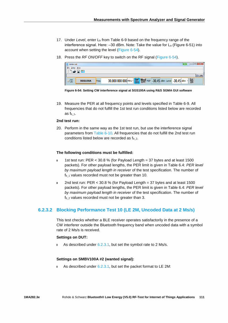
Measurements with Spectrum Analyzer and Signal Generator
1MA282.3e Rohde & Schwarz Bluetooth® Low Energy (V5.0) RF-Test for Internet of Things Applications
111
17. Under Level, enter Lb from Table 6-9 based on the frequency range of the
interference signal. Here: ‒30 dBm. Note: Take the value for La (Figure 6-51) into
account when setting the level (Figure 6-54).
18. Press the RF ON/OFF key to switch on the RF signal (Figure 6-54).
Figure 6-54: Setting CW interference signal at SGS100A using R&S SGMA GUI software
19. Measure the PER at all frequency points and levels specified in Table 6-9. All
frequencies that do not fulfill the 1st test run conditions listed below are recorded
as fb_1.
2nd test run:
20. Perform in the same way as the 1st test run, but use the interference signal
parameters from Table 6-10. All frequencies that do not fulfill the 2nd test run
conditions listed below are recorded as fb_2.
The following conditions must be fulfilled:
ı 1st test run: PER < 30.8 % (for Payload Length = 37 bytes and at least 1500
packets). For other payload lengths, the PER limit is given in Table 6.4: PER level
by maximum payload length in receiver of the test specification. The number of
fb_1 values recorded must not be greater than 10.
ı 2nd test run: PER < 30.8 % (for Payload Length = 37 bytes and at least 1500
packets). For other payload lengths, the PER limit is given in Table 6.4: PER level
by maximum payload length in receiver of the test specification. The number of
fb_2 values recorded must not be greater than 3.
6.2.3.2 Blocking Performance Test 10 (LE 2M, Uncoded Data at 2 Ms/s)
This test checks whether a BLE receiver operates satisfactorily in the presence of a
CW interferer outside the Bluetooth frequency band when uncoded data with a symbol
rate of 2 Ms/s is received.
Settings on DUT:
I As described under 6.2.3.1, but set the symbol rate to 2 Ms/s.
Settings on SMBV100A #2 (wanted signal):
I As described under 6.2.3.1, but set the packet format to LE 2M:
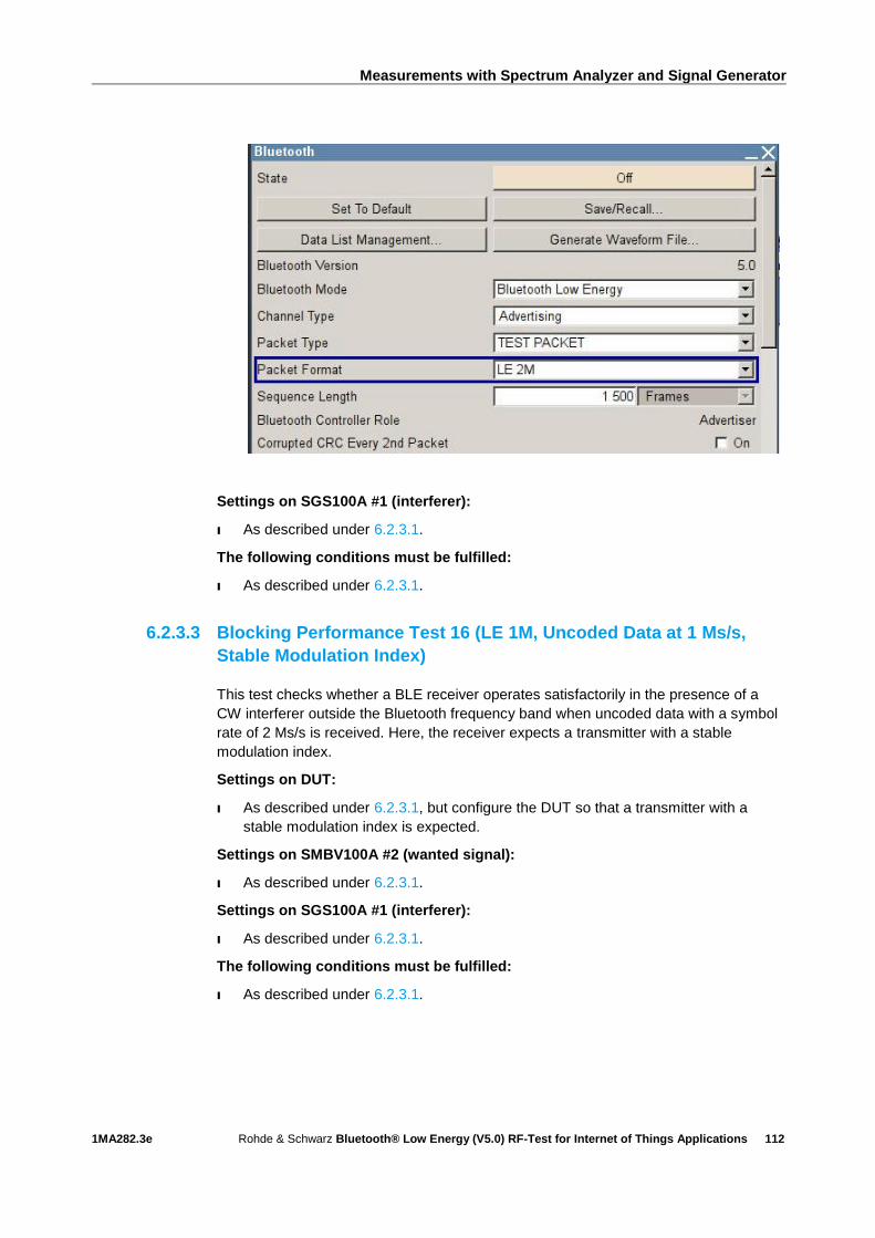
Measurements with Spectrum Analyzer and Signal Generator
1MA282.3e Rohde & Schwarz Bluetooth® Low Energy (V5.0) RF-Test for Internet of Things Applications
112
Settings on SGS100A #1 (interferer):
I As described under 6.2.3.1.
The following conditions must be fulfilled:
I As described under 6.2.3.1.
6.2.3.3 Blocking Performance Test 16 (LE 1M, Uncoded Data at 1 Ms/s,
Stable Modulation Index)
This test checks whether a BLE receiver operates satisfactorily in the presence of a
CW interferer outside the Bluetooth frequency band when uncoded data with a symbol
rate of 2 Ms/s is received. Here, the receiver expects a transmitter with a stable
modulation index.
Settings on DUT:
I As described under 6.2.3.1, but configure the DUT so that a transmitter with a
stable modulation index is expected.
Settings on SMBV100A #2 (wanted signal):
I As described under 6.2.3.1.
Settings on SGS100A #1 (interferer):
I As described under 6.2.3.1.
The following conditions must be fulfilled:
I As described under 6.2.3.1.

Measurements with Spectrum Analyzer and Signal Generator
1MA282.3e Rohde & Schwarz Bluetooth® Low Energy (V5.0) RF-Test for Internet of Things Applications
113
6.2.3.4 Blocking Performance Test 22 (LE 2M, Uncoded Data at 2 Ms/s,
Stable Modulation Index)
This test checks whether a BLE receiver operates satisfactorily in the presence of a
CW interferer outside the Bluetooth frequency band when uncoded data with a symbol
rate of 2 Ms/s is received. Here, the receiver expects a transmitter with a stable
modulation index.
Settings on DUT:
I As described under 6.2.3.1, but set the symbol rate to 2 Ms/s and configure the
DUT so that a transmitter with a stable modulation index is expected.
Settings on SMBV100A #2 (wanted signal):
I As described under 6.2.3.1, but set the packet format to LE 2M:
Settings on SGS100A #1 (interferer):
I As described under 6.2.3.1.
The following conditions must be fulfilled:
I As described under 6.2.3.1.
6.2.4 Intermodulation Performance
This test checks the behavior of the receiver under the influence of two signals. The
first interferer is an unmodulated signal (CW). The second interferer is a continuously
modulated Bluetooth signal. The interferers are set with specific levels and frequency
spacing from the wanted Bluetooth signal. The PER is measured on the wanted signal.
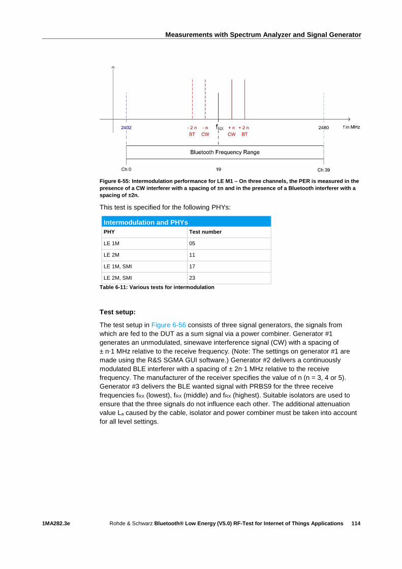
Measurements with Spectrum Analyzer and Signal Generator
1MA282.3e Rohde & Schwarz Bluetooth® Low Energy (V5.0) RF-Test for Internet of Things Applications
114
Figure 6-55: Intermodulation performance for LE M1 – On three channels, the PER is measured in the
presence of a CW interferer with a spacing of ±n and in the presence of a Bluetooth interferer with a
spacing of ±2n.
This test is specified for the following PHYs:
Intermodulation and PHYs
PHY Test number
LE 1M 05
LE 2M 11
LE 1M, SMI 17
LE 2M, SMI 23
Table 6-11: Various tests for intermodulation
Test setup:
The test setup in Figure 6-56 consists of three signal generators, the signals from
which are fed to the DUT as a sum signal via a power combiner. Generator #1
generates an unmodulated, sinewave interference signal (CW) with a spacing of
± n∙1 MHz relative to the receive frequency. (Note: The settings on generator #1 are
made using the R&S SGMA GUI software.) Generator #2 delivers a continuously
modulated BLE interferer with a spacing of ± 2n∙1 MHz relative to the receive
frequency. The manufacturer of the receiver specifies the value of n (n = 3, 4 or 5).
Generator #3 delivers the BLE wanted signal with PRBS9 for the three receive
frequencies fRX (lowest), fRX (middle) and fRX (highest). Suitable isolators are used to
ensure that the three signals do not influence each other. The additional attenuation
value La caused by the cable, isolator and power combiner must be taken into account
for all level settings.
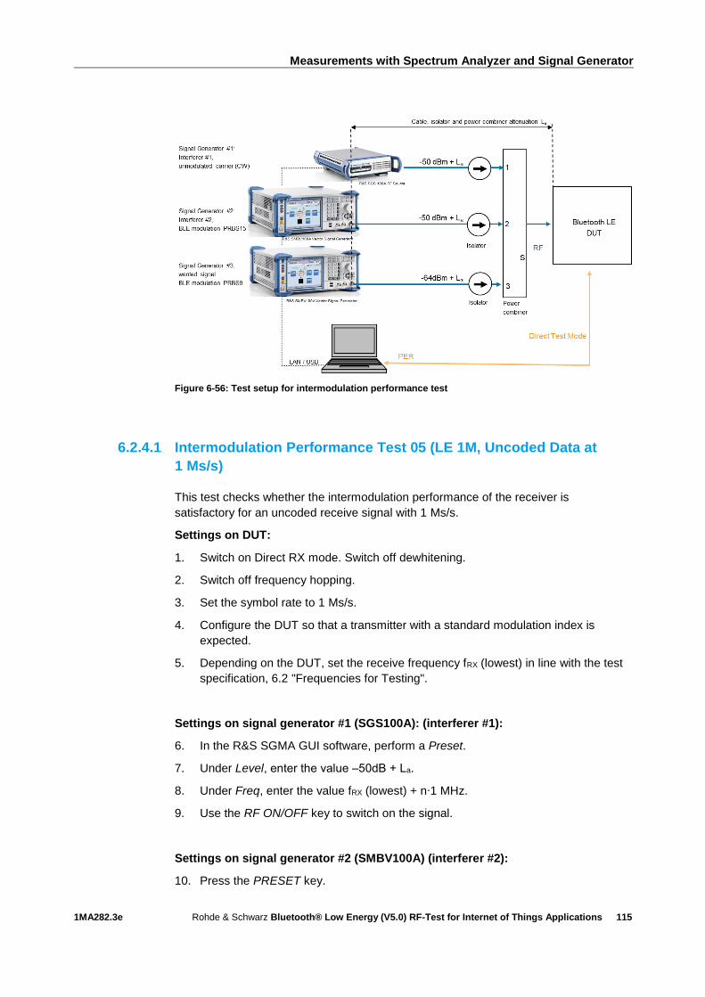
Measurements with Spectrum Analyzer and Signal Generator
1MA282.3e Rohde & Schwarz Bluetooth® Low Energy (V5.0) RF-Test for Internet of Things Applications
115
Figure 6-56: Test setup for intermodulation performance test
6.2.4.1 Intermodulation Performance Test 05 (LE 1M, Uncoded Data at
1 Ms/s)
This test checks whether the intermodulation performance of the receiver is
satisfactory for an uncoded receive signal with 1 Ms/s.
Settings on DUT:
1. Switch on Direct RX mode. Switch off dewhitening.
2. Switch off frequency hopping.
3. Set the symbol rate to 1 Ms/s.
4. Configure the DUT so that a transmitter with a standard modulation index is
expected.
5. Depending on the DUT, set the receive frequency fRX (lowest) in line with the test
specification, 6.2 "Frequencies for Testing".
Settings on signal generator #1 (SGS100A): (interferer #1):
6. In the R&S SGMA GUI software, perform a Preset.
7. Under Level, enter the value ‒50dB + La.
8. Under Freq, enter the value fRX (lowest) + n∙1 MHz.
9. Use the RF ON/OFF key to switch on the signal.
Settings on signal generator #2 (SMBV100A) (interferer #2):
10. Press the PRESET key.
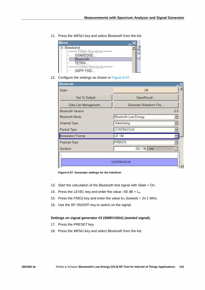
Measurements with Spectrum Analyzer and Signal Generator
1MA282.3e Rohde & Schwarz Bluetooth® Low Energy (V5.0) RF-Test for Internet of Things Applications
116
11. Press the MENU key and select Bluetooth from the list:
12. Configure the settings as shown in Figure 6-57.
Figure 6-57: Generator settings for the interferer
13. Start the calculation of the Bluetooth test signal with State = On.
14. Press the LEVEL key and enter the value ‒50 dB + La.
15. Press the FREQ key and enter the value fRX (lowest) + 2n∙1 MHz.
16. Use the RF ON/OFF key to switch on the signal.
Settings on signal generator #3 (SMBV100A) (wanted signal):
17. Press the PRESET key.
18. Press the MENU key and select Bluetooth from the list:
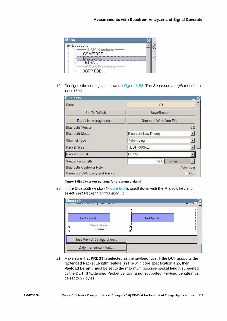
Measurements with Spectrum Analyzer and Signal Generator
1MA282.3e Rohde & Schwarz Bluetooth® Low Energy (V5.0) RF-Test for Internet of Things Applications
117
19. Configure the settings as shown in Figure 6-58. The Sequence Length must be at
least 1500.
Figure 6-58: Generator settings for the wanted signal
20. In the Bluetooth window (Figure 6-58), scroll down with the arrow key and
select Test Packet Configuration…:
21. Make sure that PRBS9 is selected as the payload type. If the DUT supports the
"Extended Packet Length" feature (in line with core specification 4.2), then
Payload Length must be set to the maximum possible packet length supported
by the DUT. If "Extended Packet Length" is not supported, Payload Length must
be set to 37 bytes:
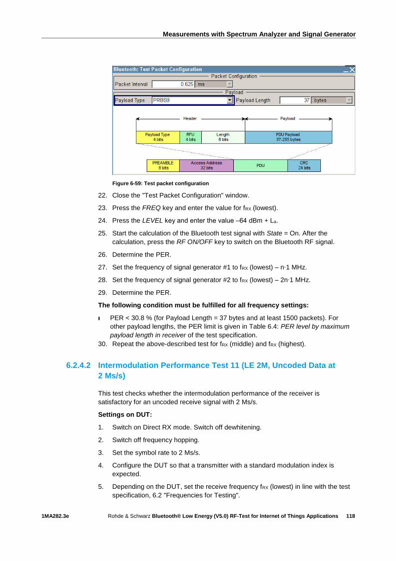
Measurements with Spectrum Analyzer and Signal Generator
1MA282.3e Rohde & Schwarz Bluetooth® Low Energy (V5.0) RF-Test for Internet of Things Applications
118
Figure 6-59: Test packet configuration
22. Close the "Test Packet Configuration" window.
23. Press the FREQ key and enter the value for fRX (lowest).
24. Press the LEVEL key and enter the value ‒64 dBm + La.
25. Start the calculation of the Bluetooth test signal with State = On. After the
calculation, press the RF ON/OFF key to switch on the Bluetooth RF signal.
26. Determine the PER.
27. Set the frequency of signal generator #1 to fRX (lowest) – n∙1 MHz.
28. Set the frequency of signal generator #2 to fRX (lowest) – 2n∙1 MHz.
29. Determine the PER.
The following condition must be fulfilled for all frequency settings:
I PER < 30.8 % (for Payload Length = 37 bytes and at least 1500 packets). For
other payload lengths, the PER limit is given in Table 6.4: PER level by maximum
payload length in receiver of the test specification.
30. Repeat the above-described test for fRX (middle) and fRX (highest).
6.2.4.2 Intermodulation Performance Test 11 (LE 2M, Uncoded Data at
2 Ms/s)
This test checks whether the intermodulation performance of the receiver is
satisfactory for an uncoded receive signal with 2 Ms/s.
Settings on DUT:
1. Switch on Direct RX mode. Switch off dewhitening.
2. Switch off frequency hopping.
3. Set the symbol rate to 2 Ms/s.
4. Configure the DUT so that a transmitter with a standard modulation index is
expected.
5. Depending on the DUT, set the receive frequency fRX (lowest) in line with the test
specification, 6.2 "Frequencies for Testing".
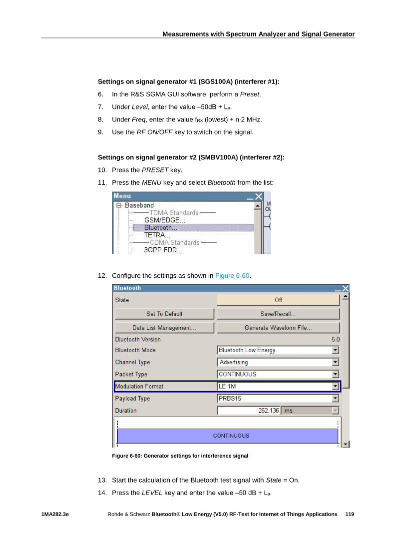
Measurements with Spectrum Analyzer and Signal Generator
1MA282.3e Rohde & Schwarz Bluetooth® Low Energy (V5.0) RF-Test for Internet of Things Applications
119
Settings on signal generator #1 (SGS100A) (interferer #1):
6. In the R&S SGMA GUI software, perform a Preset.
7. Under Level, enter the value ‒50dB + La.
8. Under Freq, enter the value fRX (lowest) + n∙2 MHz.
9. Use the RF ON/OFF key to switch on the signal.
Settings on signal generator #2 (SMBV100A) (interferer #2):
10. Press the PRESET key.
11. Press the MENU key and select Bluetooth from the list:
12. Configure the settings as shown in Figure 6-60.
Figure 6-60: Generator settings for interference signal
13. Start the calculation of the Bluetooth test signal with State = On.
14. Press the LEVEL key and enter the value ‒50 dB + La.

Measurements with Spectrum Analyzer and Signal Generator
1MA282.3e Rohde & Schwarz Bluetooth® Low Energy (V5.0) RF-Test for Internet of Things Applications
120
15. Press the FREQ key and enter the value fRX (lowest) + 2n∙2 MHz.
16. Use the RF ON/OFF key to switch on the signal.
Settings on signal generator #3 (SMBV100A) (wanted signal):
17. Press the PRESET key.
18. Press the MENU key and select Bluetooth from the list:
19. Configure the settings as shown in Figure 6-61. The Sequence Length must be at
least 1500.
20. Figure 6-61: Generator settings for wanted signal
21. In the Bluetooth window (Figure 6-61), scroll down with the arrow key and
select Test Packet Configuration…:

Measurements with Spectrum Analyzer and Signal Generator
1MA282.3e Rohde & Schwarz Bluetooth® Low Energy (V5.0) RF-Test for Internet of Things Applications
121
22. Make sure that PRBS9 is selected as the payload type. If the DUT supports the
"Extended Packet Length" feature (in line with core specification 4.2), then
Payload Length must be set to the maximum possible packet length supported
by the DUT. If "Extended Packet Length" is not supported, Payload Length must
be set to 37 bytes:
Figure 6-62: Test packet configuration
23. Close the "Test Packet Configuration" window.
24. Press the FREQ key and enter the value for fRX (lowest).
25. Press the LEVEL key and enter the value ‒64 dBm + La.
26. Start the calculation of the Bluetooth test signal with State = On. After the
calculation, press the RF ON/OFF key to switch on the Bluetooth RF signal.
27. Set the frequency of signal generator #1 to fRX (lowest) – n∙1 MHz.
28. Set the frequency of signal generator #2 to fRX (lowest) – 2n∙1 MHz.
The following condition must be fulfilled for all frequency settings:
I PER < 30.8 % (for Payload Length = 37 bytes and at least 1500 packets). For
other payload lengths, the PER limit is given in Table 6.4: PER level by maximum
payload length in receiver of the test specification.
29. Repeat the above test for fRX (middle) and fRX (highest).

Measurements with Spectrum Analyzer and Signal Generator
1MA282.3e Rohde & Schwarz Bluetooth® Low Energy (V5.0) RF-Test for Internet of Things Applications
122
6.2.4.3 Intermodulation Performance Test 17 (LE 1M, Uncoded Data at
1 Ms/s, Stable Modulation Index)
This test checks whether the intermodulation performance of the receiver is
satisfactory for an uncoded receive signal with 1 Ms/s. The receiver expects a
transmitter with a stable modulation index.
Settings on DUT:
I As described under 6.2.4.1, but configure the receiver so that a transmitter with a
stable modulation index is expected.
Settings on signal generator #1 (SGS100A) (interferer #1):
I As described under 6.2.4.1.
Settings on signal generator #2 (SMBV100A) (interferer #2):
I As described under 6.2.4.1.
Settings on signal generator #3 (SMBV100A) (wanted signal):
I As described under 6.2.4.1.
The following condition must be fulfilled for all frequency settings:
I As described under 6.2.4.1.
6.2.4.4 Intermodulation Performance Test 23 (LE 2M, Uncoded Data at
2 Ms/s, Stable Modulation Index)
This test checks whether the intermodulation performance of the receiver is
satisfactory for an uncoded receive signal with 2 Ms/s. The receiver expects a
transmitter with a stable modulation index.
Settings on DUT:
As described under 6.2.4.2, but configure the receiver so that a transmitter with a
stable modulation index is expected.
Settings on signal generator #1 (SGS100A) (interferer #1):
I As described under 6.2.4.2.
Settings on signal generator #2 (SMBV100A) (interferer #2):
I As described under 6.2.4.2.
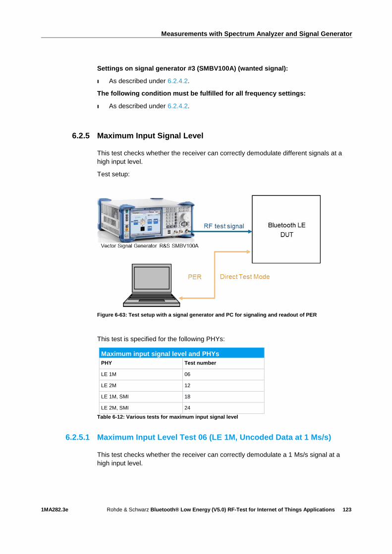
Measurements with Spectrum Analyzer and Signal Generator
1MA282.3e Rohde & Schwarz Bluetooth® Low Energy (V5.0) RF-Test for Internet of Things Applications
123
Settings on signal generator #3 (SMBV100A) (wanted signal):
I As described under 6.2.4.2.
The following condition must be fulfilled for all frequency settings:
I As described under 6.2.4.2.
6.2.5 Maximum Input Signal Level
This test checks whether the receiver can correctly demodulate different signals at a
high input level.
Test setup:
Figure 6-63: Test setup with a signal generator and PC for signaling and readout of PER
This test is specified for the following PHYs:
Maximum input signal level and PHYs
PHY Test number
LE 1M 06
LE 2M 12
LE 1M, SMI 18
LE 2M, SMI 24
Table 6-12: Various tests for maximum input signal level
6.2.5.1 Maximum Input Level Test 06 (LE 1M, Uncoded Data at 1 Ms/s)
This test checks whether the receiver can correctly demodulate a 1 Ms/s signal at a
high input level.

Measurements with Spectrum Analyzer and Signal Generator
1MA282.3e Rohde & Schwarz Bluetooth® Low Energy (V5.0) RF-Test for Internet of Things Applications
124
Settings on DUT:
1. Switch on Direct RX mode. Switch off dewhitening.
2. Switch off frequency hopping.
3. Set the symbol rate to 1 Ms/s.
4. Configure the DUT so that a transmitter with a standard modulation index is
expected.
5. Depending on the DUT, set the receive frequency fTX (lowest) in line with the test
specification, 6.2 "Frequencies for Testing".
Settings on SMBV100A:
6. Press the PRESET key.
7. Press the MENU key and select Bluetooth from the list:
8. Configure the settings as shown in Figure 6-64. The Sequence Length must be at
least 1500.
Figure 6-64: Generator settings for Maximum Input Level Test 06
9. In the Bluetooth window (Figure 6-64), scroll down with the arrow key and
select Test Packet Configuration…:
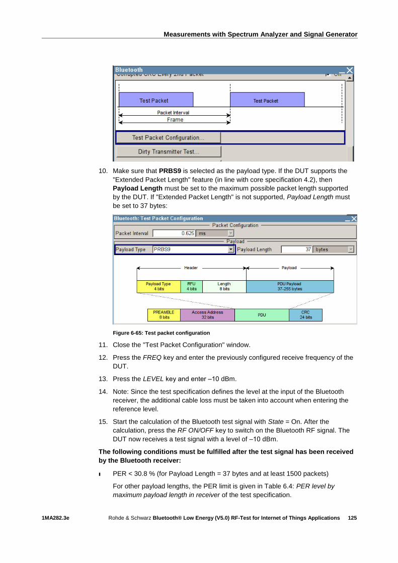
Measurements with Spectrum Analyzer and Signal Generator
1MA282.3e Rohde & Schwarz Bluetooth® Low Energy (V5.0) RF-Test for Internet of Things Applications
125
10. Make sure that PRBS9 is selected as the payload type. If the DUT supports the
"Extended Packet Length" feature (in line with core specification 4.2), then
Payload Length must be set to the maximum possible packet length supported
by the DUT. If "Extended Packet Length" is not supported, Payload Length must
be set to 37 bytes:
Figure 6-65: Test packet configuration
11. Close the "Test Packet Configuration" window.
12. Press the FREQ key and enter the previously configured receive frequency of the
DUT.
13. Press the LEVEL key and enter ‒10 dBm.
14. Note: Since the test specification defines the level at the input of the Bluetooth
receiver, the additional cable loss must be taken into account when entering the
reference level.
15. Start the calculation of the Bluetooth test signal with State = On. After the
calculation, press the RF ON/OFF key to switch on the Bluetooth RF signal. The
DUT now receives a test signal with a level of ‒10 dBm.
The following conditions must be fulfilled after the test signal has been received
by the Bluetooth receiver:
ı PER < 30.8 % (for Payload Length = 37 bytes and at least 1500 packets)
For other payload lengths, the PER limit is given in Table 6.4: PER level by
maximum payload length in receiver of the test specification.
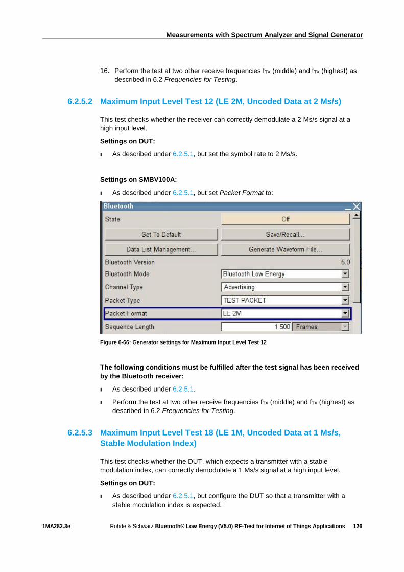
Measurements with Spectrum Analyzer and Signal Generator
1MA282.3e Rohde & Schwarz Bluetooth® Low Energy (V5.0) RF-Test for Internet of Things Applications
126
16. Perform the test at two other receive frequencies fTX (middle) and fTX (highest) as
described in 6.2 Frequencies for Testing.
6.2.5.2 Maximum Input Level Test 12 (LE 2M, Uncoded Data at 2 Ms/s)
This test checks whether the receiver can correctly demodulate a 2 Ms/s signal at a
high input level.
Settings on DUT:
I As described under 6.2.5.1, but set the symbol rate to 2 Ms/s.
Settings on SMBV100A:
I As described under 6.2.5.1, but set Packet Format to:
Figure 6-66: Generator settings for Maximum Input Level Test 12
The following conditions must be fulfilled after the test signal has been received
by the Bluetooth receiver:
I As described under 6.2.5.1.
I Perform the test at two other receive frequencies fTX (middle) and fTX (highest) as
described in 6.2 Frequencies for Testing.
6.2.5.3 Maximum Input Level Test 18 (LE 1M, Uncoded Data at 1 Ms/s,
Stable Modulation Index)
This test checks whether the DUT, which expects a transmitter with a stable
modulation index, can correctly demodulate a 1 Ms/s signal at a high input level.
Settings on DUT:
I As described under 6.2.5.1, but configure the DUT so that a transmitter with a
stable modulation index is expected.
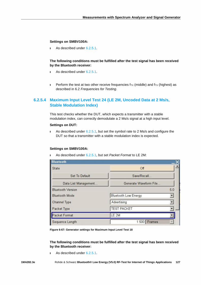
Measurements with Spectrum Analyzer and Signal Generator
1MA282.3e Rohde & Schwarz Bluetooth® Low Energy (V5.0) RF-Test for Internet of Things Applications
127
Settings on SMBV100A:
I As described under 6.2.5.1.
The following conditions must be fulfilled after the test signal has been received
by the Bluetooth receiver:
I As described under 6.2.5.1.
I Perform the test at two other receive frequencies fTX (middle) and fTX (highest) as
described in 6.2 Frequencies for Testing.
6.2.5.4 Maximum Input Level Test 24 (LE 2M, Uncoded Data at 2 Ms/s,
Stable Modulation Index)
This test checks whether the DUT, which expects a transmitter with a stable
modulation index, can correctly demodulate a 2 Ms/s signal at a high input level.
Settings on DUT:
I As described under 6.2.5.1, but set the symbol rate to 2 Ms/s and configure the
DUT so that a transmitter with a stable modulation index is expected.
Settings on SMBV100A:
I As described under 6.2.5.1, but set Packet Format to LE 2M:
Figure 6-67: Generator settings for Maximum Input Level Test 18
The following conditions must be fulfilled after the test signal has been received
by the Bluetooth receiver:
I As described under 6.2.5.1.
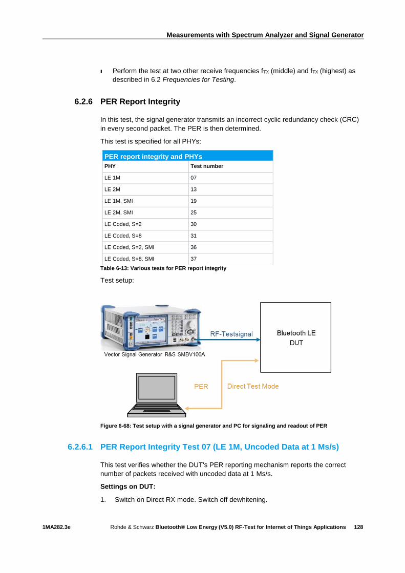
Measurements with Spectrum Analyzer and Signal Generator
1MA282.3e Rohde & Schwarz Bluetooth® Low Energy (V5.0) RF-Test for Internet of Things Applications
128
I Perform the test at two other receive frequencies fTX (middle) and fTX (highest) as
described in 6.2 Frequencies for Testing.
6.2.6 PER Report Integrity
In this test, the signal generator transmits an incorrect cyclic redundancy check (CRC)
in every second packet. The PER is then determined.
This test is specified for all PHYs:
PER report integrity and PHYs
PHY Test number
LE 1M 07
LE 2M 13
LE 1M, SMI 19
LE 2M, SMI 25
LE Coded, S=2 30
LE Coded, S=8 31
LE Coded, S=2, SMI 36
LE Coded, S=8, SMI 37
Table 6-13: Various tests for PER report integrity
Test setup:
Figure 6-68: Test setup with a signal generator and PC for signaling and readout of PER
6.2.6.1 PER Report Integrity Test 07 (LE 1M, Uncoded Data at 1 Ms/s)
This test verifies whether the DUT's PER reporting mechanism reports the correct
number of packets received with uncoded data at 1 Ms/s.
Settings on DUT:
1. Switch on Direct RX mode. Switch off dewhitening.
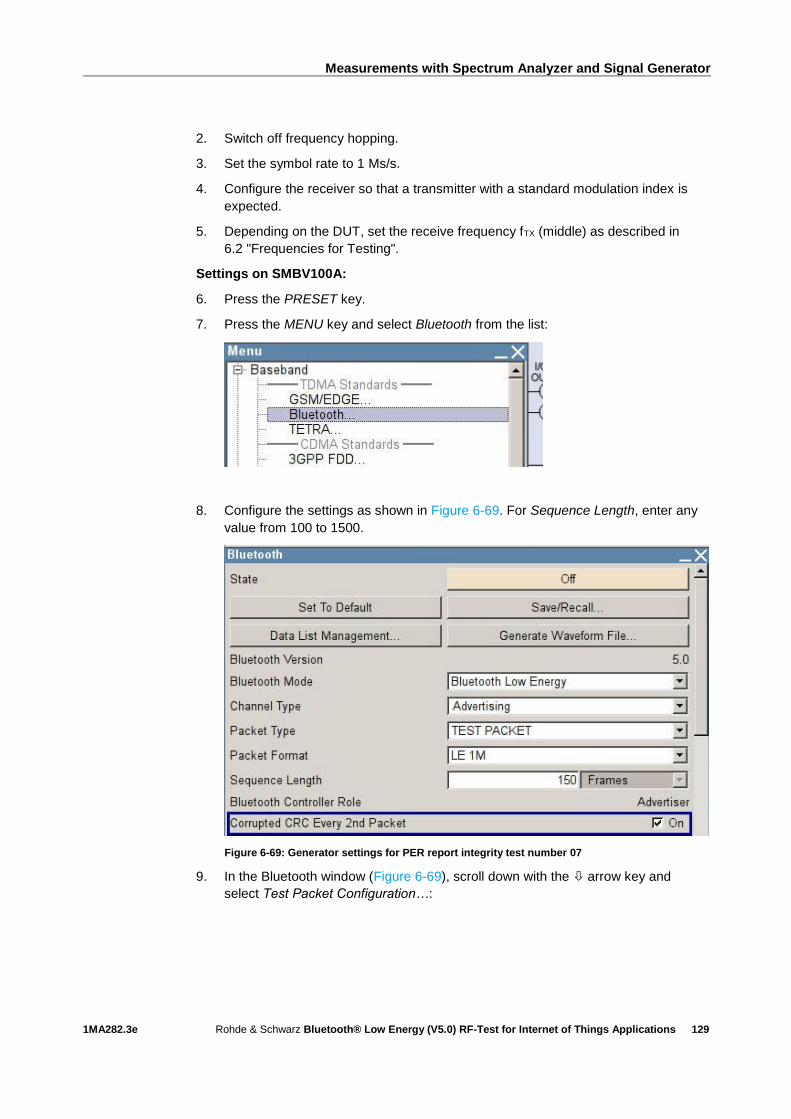
Measurements with Spectrum Analyzer and Signal Generator
1MA282.3e Rohde & Schwarz Bluetooth® Low Energy (V5.0) RF-Test for Internet of Things Applications
129
2. Switch off frequency hopping.
3. Set the symbol rate to 1 Ms/s.
4. Configure the receiver so that a transmitter with a standard modulation index is
expected.
5. Depending on the DUT, set the receive frequency fTX (middle) as described in
6.2 "Frequencies for Testing".
Settings on SMBV100A:
6. Press the PRESET key.
7. Press the MENU key and select Bluetooth from the list:
8. Configure the settings as shown in Figure 6-69. For Sequence Length, enter any
value from 100 to 1500.
Figure 6-69: Generator settings for PER report integrity test number 07
9. In the Bluetooth window (Figure 6-69), scroll down with the arrow key and
select Test Packet Configuration…:
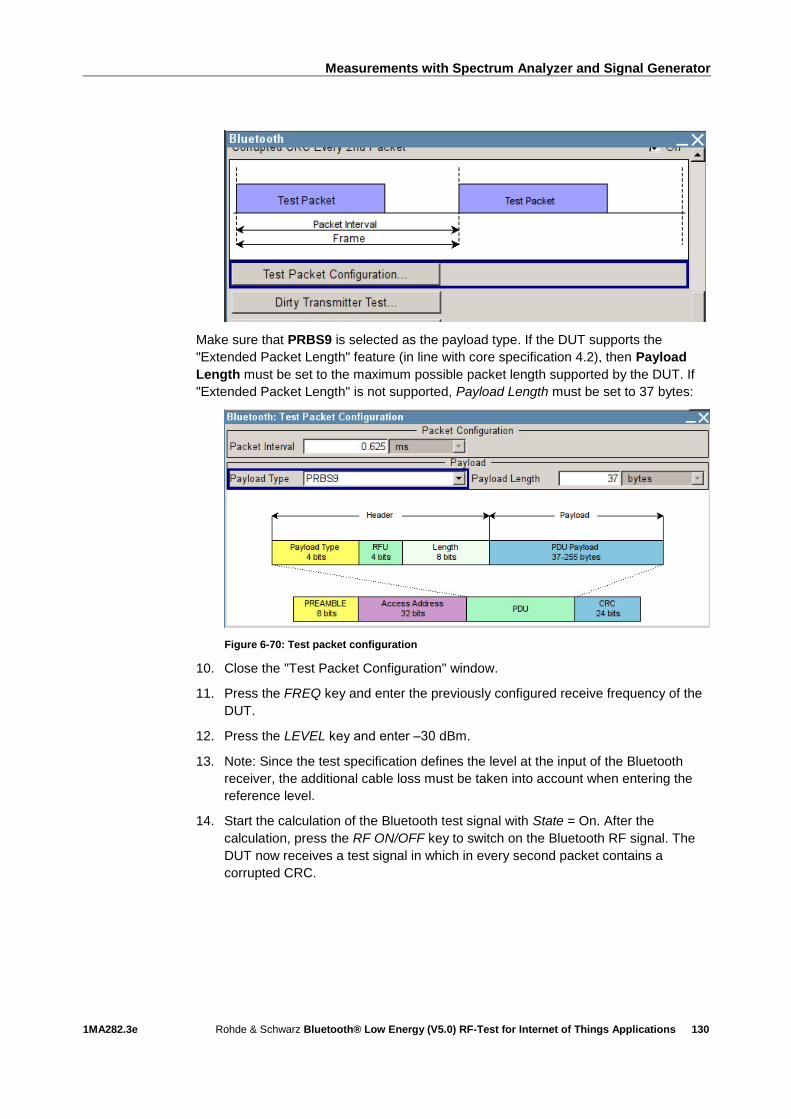
Measurements with Spectrum Analyzer and Signal Generator
1MA282.3e Rohde & Schwarz Bluetooth® Low Energy (V5.0) RF-Test for Internet of Things Applications
130
Make sure that PRBS9 is selected as the payload type. If the DUT supports the
"Extended Packet Length" feature (in line with core specification 4.2), then Payload
Length must be set to the maximum possible packet length supported by the DUT. If
"Extended Packet Length" is not supported, Payload Length must be set to 37 bytes:
Figure 6-70: Test packet configuration
10. Close the "Test Packet Configuration" window.
11. Press the FREQ key and enter the previously configured receive frequency of the
DUT.
12. Press the LEVEL key and enter ‒30 dBm.
13. Note: Since the test specification defines the level at the input of the Bluetooth
receiver, the additional cable loss must be taken into account when entering the
reference level.
14. Start the calculation of the Bluetooth test signal with State = On. After the
calculation, press the RF ON/OFF key to switch on the Bluetooth RF signal. The
DUT now receives a test signal in which in every second packet contains a
corrupted CRC.
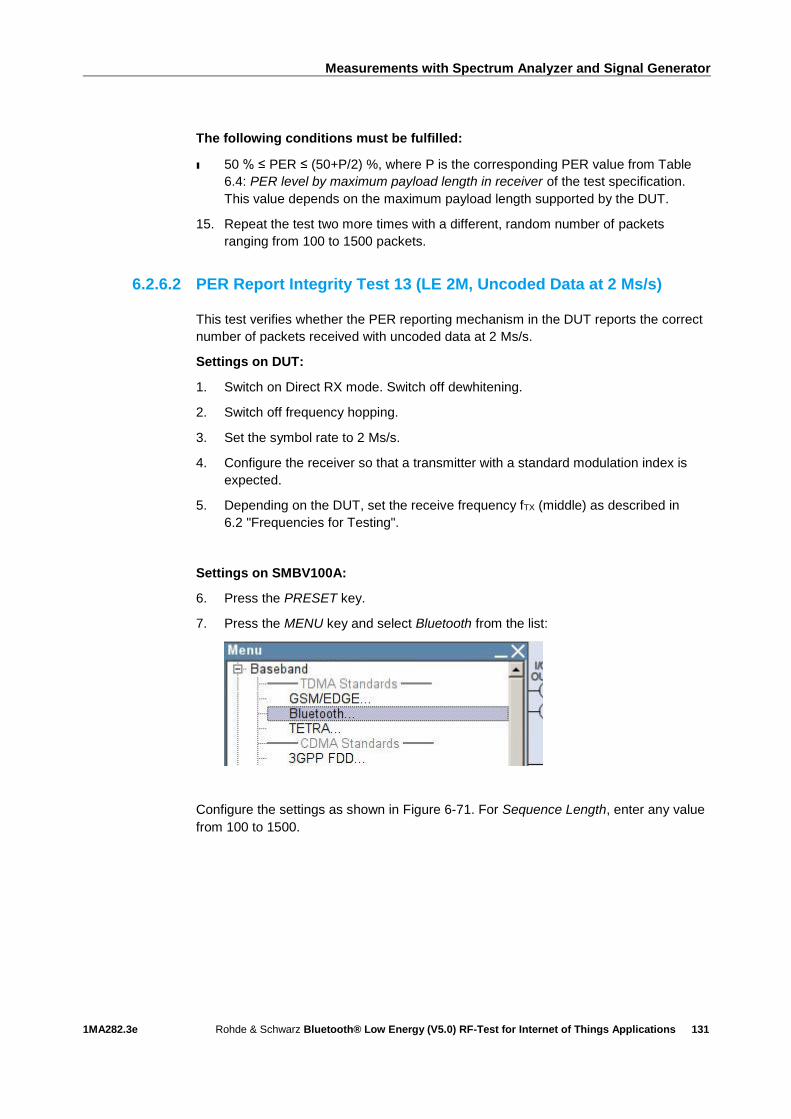
Measurements with Spectrum Analyzer and Signal Generator
1MA282.3e Rohde & Schwarz Bluetooth® Low Energy (V5.0) RF-Test for Internet of Things Applications
131
The following conditions must be fulfilled:
ı 50 % ≤ PER ≤ (50+P/2) %, where P is the corresponding PER value from Table
6.4: PER level by maximum payload length in receiver of the test specification.
This value depends on the maximum payload length supported by the DUT.
15. Repeat the test two more times with a different, random number of packets
ranging from 100 to 1500 packets.
6.2.6.2 PER Report Integrity Test 13 (LE 2M, Uncoded Data at 2 Ms/s)
This test verifies whether the PER reporting mechanism in the DUT reports the correct
number of packets received with uncoded data at 2 Ms/s.
Settings on DUT:
1. Switch on Direct RX mode. Switch off dewhitening.
2. Switch off frequency hopping.
3. Set the symbol rate to 2 Ms/s.
4. Configure the receiver so that a transmitter with a standard modulation index is
expected.
5. Depending on the DUT, set the receive frequency fTX (middle) as described in
6.2 "Frequencies for Testing".
Settings on SMBV100A:
6. Press the PRESET key.
7. Press the MENU key and select Bluetooth from the list:
Configure the settings as shown in Figure 6-71. For Sequence Length, enter any value
from 100 to 1500.

Measurements with Spectrum Analyzer and Signal Generator
1MA282.3e Rohde & Schwarz Bluetooth® Low Energy (V5.0) RF-Test for Internet of Things Applications
132
Figure 6-71: Generator settings for PER report integrity test number 13
8. In the Bluetooth window (Figure 6-71), scroll down with the arrow key and
select Test Packet Configuration…:
9. Make sure that PRBS9 is selected as the payload type. If the DUT supports the
"Extended Packet Length" feature (in line with core specification 4.2), then
Payload Length must be set to the maximum possible packet length supported
by the DUT. If "Extended Packet Length" is not supported, Payload Length must
be set to 37 bytes:

Measurements with Spectrum Analyzer and Signal Generator
1MA282.3e Rohde & Schwarz Bluetooth® Low Energy (V5.0) RF-Test for Internet of Things Applications
133
Figure 6-72: Test packet configuration
10. Close the "Test Packet Configuration" window.
11. Press the FREQ key and enter the previously configured receive frequency of the
DUT.
12. Press the LEVEL key and enter ‒30 dBm.
13. Note: Since the test specification defines the level at the input of the Bluetooth
receiver, the additional cable loss must be taken into account when entering the
reference level.
14. Start the calculation of the Bluetooth test signal with State = On. After the
calculation, press the RF ON/OFF key to switch on the Bluetooth RF signal. The
DUT now receives a test signal in which in every second packet contains a
corrupted CRC.
The following conditions must be fulfilled:
ı 50 % ≤ PER ≤ (50+P/2) %, where P is the corresponding PER value from Table
6.4 of the test specification. This value depends on the maximum payload length
supported by the DUT.
15. Repeat the test two more times with a different, random number of packets
ranging from 100 to 1500 packets.
6.2.6.3 PER Report Integrity Test 19 (LE 1M, Uncoded Data at 1 Ms/s,
Stable Modulation Index)
This test verifies whether the PER reporting mechanism in the DUT reports the correct
number of packets received at 1 Ms/s when the DUT expects a transmitter with a
stable modulation index.
Settings on DUT:
I As described under 6.2.6.1, but configure the receiver so that a transmitter with a
stable modulation index is expected.

Measurements with Spectrum Analyzer and Signal Generator
1MA282.3e Rohde & Schwarz Bluetooth® Low Energy (V5.0) RF-Test for Internet of Things Applications
134
Settings on SMBV100A:
I As described under 6.2.6.1.
The following conditions must be fulfilled:
I As described under 6.2.6.1.
6.2.6.4 PER Report Integrity Test 25 (LE 2M, Uncoded Data at 2 Ms/s,
Stable Modulation Index)
This test verifies whether the PER reporting mechanism in the DUT reports the correct
number of packets received at 2 Ms/s when the DUT expects a transmitter with a
stable modulation index.
Settings on DUT:
I As described under 6.2.6.2, but configure the receiver so that a transmitter with a
stable modulation index is expected.
Settings on SMBV100A:
I As described under 6.2.6.2.
The following conditions must be fulfilled:
I As described under 6.2.6.2.
6.2.6.5 PER Report Integrity Test 30 (LE Coded, S=2)
This test verifies whether the PER reporting mechanism in the DUT reports the correct
number of packets received when the DUT uses LE Coded PHY with data coding
S = 2.
Settings on DUT:
I As described under 6.2.6.1, but do not set the receiver symbol rate to 1 Ms/s;
instead, set the receiver to LE Coded PHY with data coding S = 2.
Settings on SMBV100A:
As described under 6.2.6.1, but:
I Under Packet Format, set LE Coded:
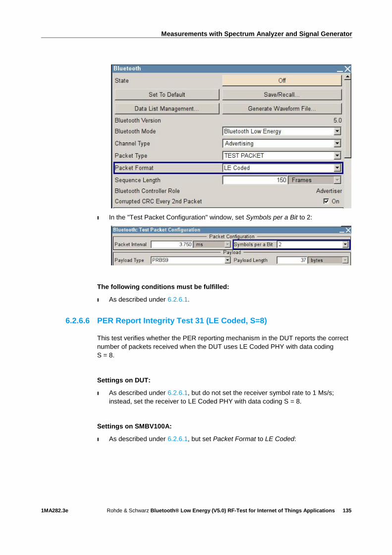
Measurements with Spectrum Analyzer and Signal Generator
1MA282.3e Rohde & Schwarz Bluetooth® Low Energy (V5.0) RF-Test for Internet of Things Applications
135
I In the "Test Packet Configuration" window, set Symbols per a Bit to 2:
The following conditions must be fulfilled:
I As described under 6.2.6.1.
6.2.6.6 PER Report Integrity Test 31 (LE Coded, S=8)
This test verifies whether the PER reporting mechanism in the DUT reports the correct
number of packets received when the DUT uses LE Coded PHY with data coding
S = 8.
Settings on DUT:
I As described under 6.2.6.1, but do not set the receiver symbol rate to 1 Ms/s;
instead, set the receiver to LE Coded PHY with data coding S = 8.
Settings on SMBV100A:
I As described under 6.2.6.1, but set Packet Format to LE Coded:

Measurements with Spectrum Analyzer and Signal Generator
1MA282.3e Rohde & Schwarz Bluetooth® Low Energy (V5.0) RF-Test for Internet of Things Applications
136
I In the "Test Packet Configuration" window, set Symbols per a Bit to 8:
The following conditions must be fulfilled:
I As described under 6.2.6.1.
6.2.6.7 PER Report Integrity Test 36 (LE Coded, S=2, Stable Modulation
Index)
This test verifies whether the PER reporting mechanism in the DUT reports the correct
number of packets received when the DUT uses LE Coded PHY with data coding S = 2
and expects a transmitter with a stable modulation index.
Settings on DUT:
I As described under 6.2.6.1, but do not set the receiver symbol rate to 1 Ms/s;
instead, set the receiver to LE Coded PHY with data coding S = 8 and configure it
so that a transmitter with a stable modulation index is expected.
Settings on SMBV100A:
As described under 6.2.6.1, but:
I Set Packet Format to LE Coded:

Measurements with Spectrum Analyzer and Signal Generator
1MA282.3e Rohde & Schwarz Bluetooth® Low Energy (V5.0) RF-Test for Internet of Things Applications
137
I In the "Test Packet Configuration" window, set Symbols per a Bit to 2:
The following conditions must be fulfilled:
I As described under 6.2.6.1.
6.2.6.8 PER Report Integrity Test 37 (LE Coded, S=8, Stable Modulation
Index)
This test verifies whether the PER reporting mechanism in the DUT reports the correct
number of packets received when the DUT uses LE Coded PHY with data coding S = 8
and expects a transmitter with a stable modulation index.
Settings on DUT:
I As described under 6.2.6.1, but do not set the receiver symbol rate to 1 Ms/s;
instead, set the receiver to LE Coded PHY with data coding S = 2 and configure it
so that a transmitter with a stable modulation index is expected.
Settings on SMBV100A:
I As described under 6.2.6.1, but:
Set Packet Format to LE Coded:
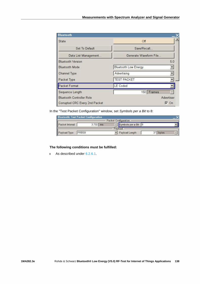
Measurements with Spectrum Analyzer and Signal Generator
1MA282.3e Rohde & Schwarz Bluetooth® Low Energy (V5.0) RF-Test for Internet of Things Applications
138
In the "Test Packet Configuration" window, set Symbols per a Bit to 8:
The following conditions must be fulfilled:
I As described under 6.2.6.1.

References
1MA282.3e Rohde & Schwarz Bluetooth® Low Energy (V5.0) RF-Test for Internet of Things Applications
139
7 References
[1] 1. Schulz, Bernhard. 1MA108. From cable replacement to the IoT: Bluetooth 5.
s.l. : Rohde & Schwarz, 2016. 3e.
[2] 2. Coupe, Cheryl. A Guide to Joining the Internet of Things. s.l. : Bluetooth SIG,
Inc, 2016.
[3] 3. Bluetooth SIG. RF PHY. Bluetooth Test Specification. December 2016. RF-
PHY.TS.5.0.0.
[4] 4. —. Bluetooth Core Specification v5.0. 06 December 2016.
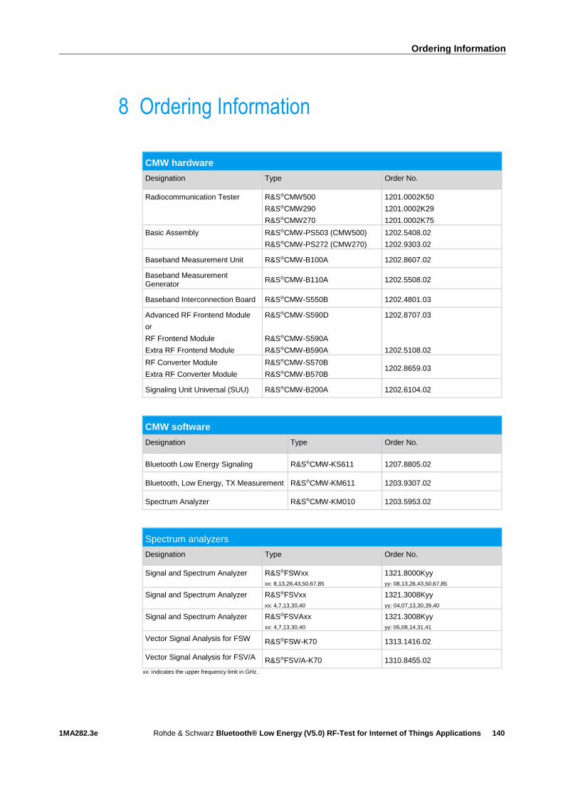
Ordering Information
1MA282.3e Rohde & Schwarz Bluetooth® Low Energy (V5.0) RF-Test for Internet of Things Applications
140
8 Ordering Information
CMW hardware
Designation Type Order No.
Radiocommunication Tester R&S®CMW500
R&S®CMW290
R&S®CMW270
1201.0002K50
1201.0002K29
1201.0002K75
Basic Assembly
R&S®CMW-PS503 (CMW500)
R&S®CMW-PS272 (CMW270)
1202.5408.02
1202.9303.02
Baseband Measurement Unit R&S®CMW-B100A 1202.8607.02
Baseband Measurement Generator
R&S®CMW-B110A 1202.5508.02
Baseband Interconnection Board R&S®CMW-S550B 1202.4801.03
Advanced RF Frontend Module
or
RF Frontend Module
Extra RF Frontend Module
R&S®CMW-S590D
R&S®CMW-S590A
R&S®CMW-B590A
1202.8707.03
1202.5108.02
RF Converter Module
Extra RF Converter Module
R&S®CMW-S570B
R&S®CMW-B570B 1202.8659.03
Signaling Unit Universal (SUU) R&S®CMW-B200A 1202.6104.02
CMW software
Designation Type Order No.
Bluetooth Low Energy Signaling R&S®CMW-KS611 1207.8805.02
Bluetooth, Low Energy, TX Measurement R&S®CMW-KM611 1203.9307.02
Spectrum Analyzer R&S®CMW-KM010 1203.5953.02
Spectrum analyzers
Designation Type Order No.
Signal and Spectrum Analyzer R&S®FSWxx
xx: 8,13,26,43,50,67,85
1321.8000Kyy
yy: 08,13,26,43,50,67,85
Signal and Spectrum Analyzer R&S®FSVxx
xx: 4,7,13,30,40
1321.3008Kyy
yy: 04,07,13,30,39,40
Signal and Spectrum Analyzer R&S®FSVAxx
xx: 4,7,13,30,40
1321.3008Kyy
yy: 05,08,14,31,41
Vector Signal Analysis for FSW R&S®FSW-K70 1313.1416.02
Vector Signal Analysis for FSV/A R&S®FSV/A-K70 1310.8455.02
xx: indicates the upper frequency limit in GHz.
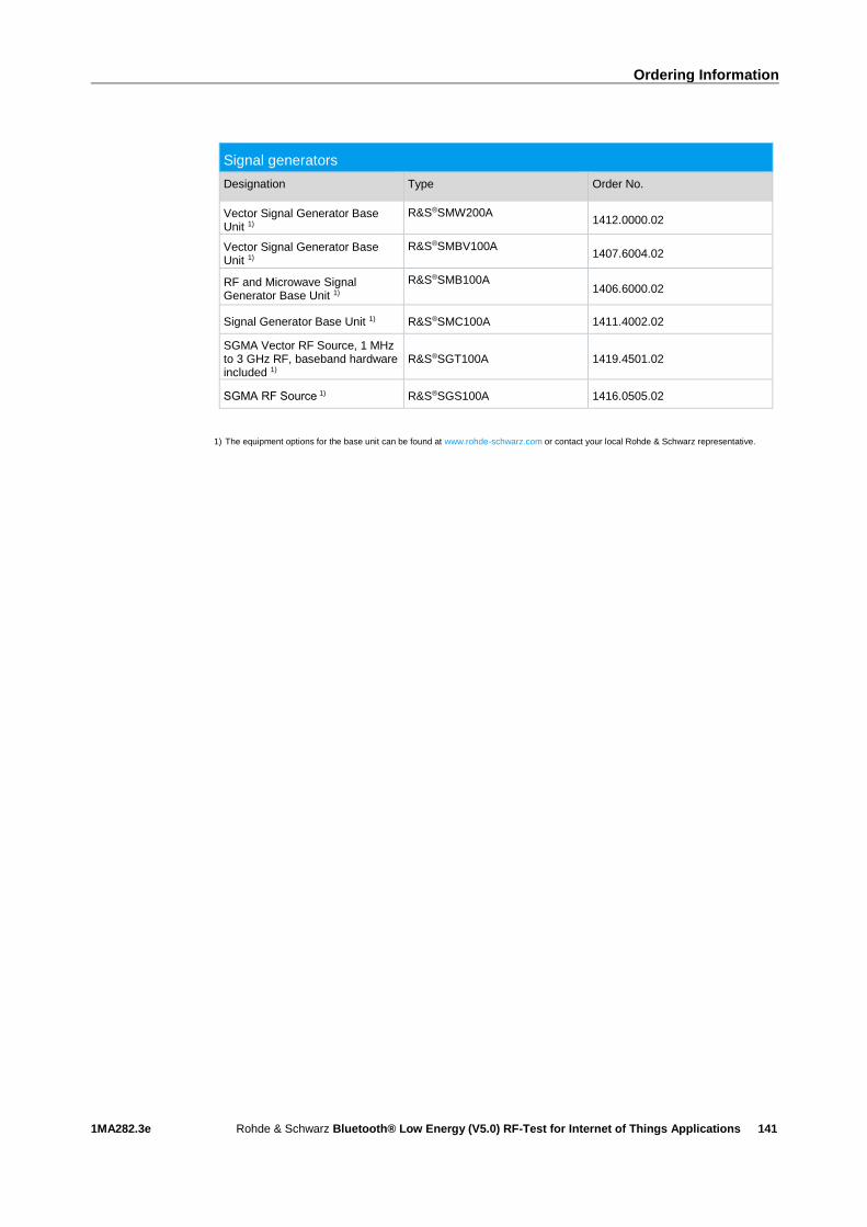
Ordering Information
1MA282.3e Rohde & Schwarz Bluetooth® Low Energy (V5.0) RF-Test for Internet of Things Applications
141
Signal generators
Designation Type Order No.
Vector Signal Generator Base Unit 1)
R&S®SMW200A
1412.0000.02
Vector Signal Generator Base Unit 1)
R&S®SMBV100A
1407.6004.02
RF and Microwave Signal Generator Base Unit 1)
R&S®SMB100A
1406.6000.02
Signal Generator Base Unit 1) R&S®SMC100A 1411.4002.02
SGMA Vector RF Source, 1 MHz to 3 GHz RF, baseband hardware included 1)
R&S®SGT100A 1419.4501.02
SGMA RF Source 1) R&S®SGS100A 1416.0505.02
1) The equipment options for the base unit can be found at www.rohde-schwarz.com or contact your local Rohde & Schwarz representative.

Rohde & Schwarz
The Rohde & Schwarz electronics group offers
innovative solutions in the following business fields:
test and measurement, broadcast and media, secure
communications, cybersecurity, monitoring and
network testing. Founded more than 80 years ago,
the independent company has an extensive sales
and service network with locations in more than 70
countries.
The electronics group ranks among the world market
leaders in its established business fields. The
company is headquartered in Munich, Germany. It
also has regional headquarters in Singapore and
Columbia, Maryland, USA, to manage its operations
in these regions.
Regional contact
Europe, Africa, Middle East +49 89 4129 12345 [email protected] North America 1 888 TEST RSA (1 888 837 87 72) [email protected] Latin America +1 410 910 79 88 [email protected] Asia Pacific +65 65 13 04 88 [email protected]
China +86 800 810 82 28 |+86 400 650 58 96 [email protected]
Sustainable product design
Environmental compatibility and eco-footprint
Power efficiency and low emissions
Longevity and optimized total cost of ownership
This document and any included programs may be
used only upon acceptance of the terms and
conditions of use as defined in the downloads area
of the Rohde & Schwarz Internet site.
R&S® is a registered trademark of Rohde & Schwarz GmbH &
Co. KG. Trade names are trademarks of the owners.
Rohde & Schwarz GmbH & Co. KG
Mühldorfstraße 15 | D - 81671 München
Phone + 49 89 4129 - 0 | Fax + 49 89 4129 – 13777
www.rohde-schwarz.com
PA
D-T
-M: 3573.7
380.0
3/0
2.0
6/D
E/