blue sky environmental - oregon
TRANSCRIPT

Source Test Plan Revised April 27, 2020
Prepared for: Chemical Waste Management of the Northwest, Inc.
18177 Cedar Springs Ln. Arlington, OR 97812
Located at: Chemical Waste Management of the Northwest, Inc.
18177 Cedar Springs Ln. Arlington, OR 97812
ODEQ Oregon PERMIT #11-0002-SI-01
Submitted to: Department of Environmental Quality 700 NE Multnomah Street, Suite 600
Portland, Oregon, 97232 [email protected]
Prepared by: Guy Worthington
BLUE SKY ENVIRONMENTAL, Inc. 624 San Gabriel Ave Albany, CA 94706
Office 510-525-1261 Mobile 510-508-3469

Blue Sky Environmental, Inc
2
GENERAL INFORMATION
Source Owner: Chemical Waste Management of the Northwest, Inc. 18177 Cedar Springs Ln Arlington, OR 97812 Source Location: Chemical Waste Management of the Northwest, Inc. 18177 Cedar Springs Ln Arlington, OR 97812 Source Contact: James Denson (PNW/BC) Environmental Protection Manager 602-757-3352 [email protected] Bob Mulholland (District Manager) Regional Contact: ODEQ-Attn: Jonathan Giska 503-229-5178 Department of Environmental Quality 700 NE Multnomah Street, Suite 600 Portland, Oregon, 97232 [email protected] Federal Contact: USEPA Region 10 N/A Source Description: Organic Recovery Unit 2 (ORU2) Permit: 11-0002-SI Regulation Requirements: Clean Air Oregon Rules Oregon DEQ Letter Dated Aug 8, 2019 Source Testing Company: BLUE SKY ENVIRONMENTAL, Inc. 624 San Gabriel Ave Albany, CA 94706 Contact: Guy Worthington 510-525-1261 or 510-508-3469 Scheduled Test Date(s): TBD
Blue Sky Environmental, Inc
3
The ODEQ requires the following statements (from Oregon Source Sampling manual Section A-1) must be included in the test plan:
1. We are requesting ODEQ to allow sampling replicate(s) if separated by a time duration of seventy-two (72) hours or less as we are proposing a three-day testing event.
2. This compliance source test will be performed while the emission unit(s) are operating at normal
operating rates. Unless defined by permit condition or applicable rule, normal operating rate is defined as the 90th percentile of the average hourly operating rates during a 12-month period immediately preceding the source test.
3. The ODEQ will be notified of any changes in the source test plan and/or the specified methods prior
to testing. Significant changes not acknowledged by the ODEQ could be the basis for invalidating a test run and potentially the entire testing program. Documentation of any deviations must include an evaluation of the impact of the deviation on the test data.
4. Method-specific quality assurance/quality control (QA/QC) procedures will be performed to ensure that
the data is valid for determining source compliance. Documentation of the procedures and results shall be presented in the source test report for review. Critical information will be included, to avoid rejection of the data, requiring a retest.
5. Only regular operating staff may adjust the combustion system or production process and emission
control parameters during the source performance tests and within two (2) hours prior to the tests. Any operating adjustments made during the source performance tests, which are a result of consultation during the tests with source testing personnel, equipment vendors or consultants, may render the source performance test invalid.
6. Source test reports will be submitted to ODEQ within thirty (30) days of the test dates, unless another
deadline has been stipulated, either by permit condition, or by ODEQ written approval. The ODEQ has stated that 60 days to submit the report is acceptable.

Blue Sky Environmental, Inc
4
1.0 Introduction This testing is planned to comply with the ODEQ emission test requirements stated in communications from Jonathan Giska of ODEQ to Jim Denson of Chemical Waste Management of the Northwest (CWM-NW) dated August 8th, 2019. Testing will produce emissions data from the Organic Recovery Unit #2 (ORU2) to be used in Air Dispersion Modelling and Risk Assessment under the Cleaner Air Oregon rule.
Specified Testing Pollutants
Metals (Sb, As, Ba, Be, Cd, Cr, Co, Cu, Pb, Mn, Hg, Ni, P, Se, Ag, Tl, Zn)+Al and V Particulates + Hydrogen Halides (HCl)
Polycyclic Aromatic Hydrocarbons, Dioxins and Furans TOU (exhaust) & (inlets) for Total Volatile Organic Compounds
Specific Toxic Organic Compounds at Thermal Oxidizer Unit TOU Inlet & Outlet
The methods used for testing these pollutants are described in Section 3.0 below.
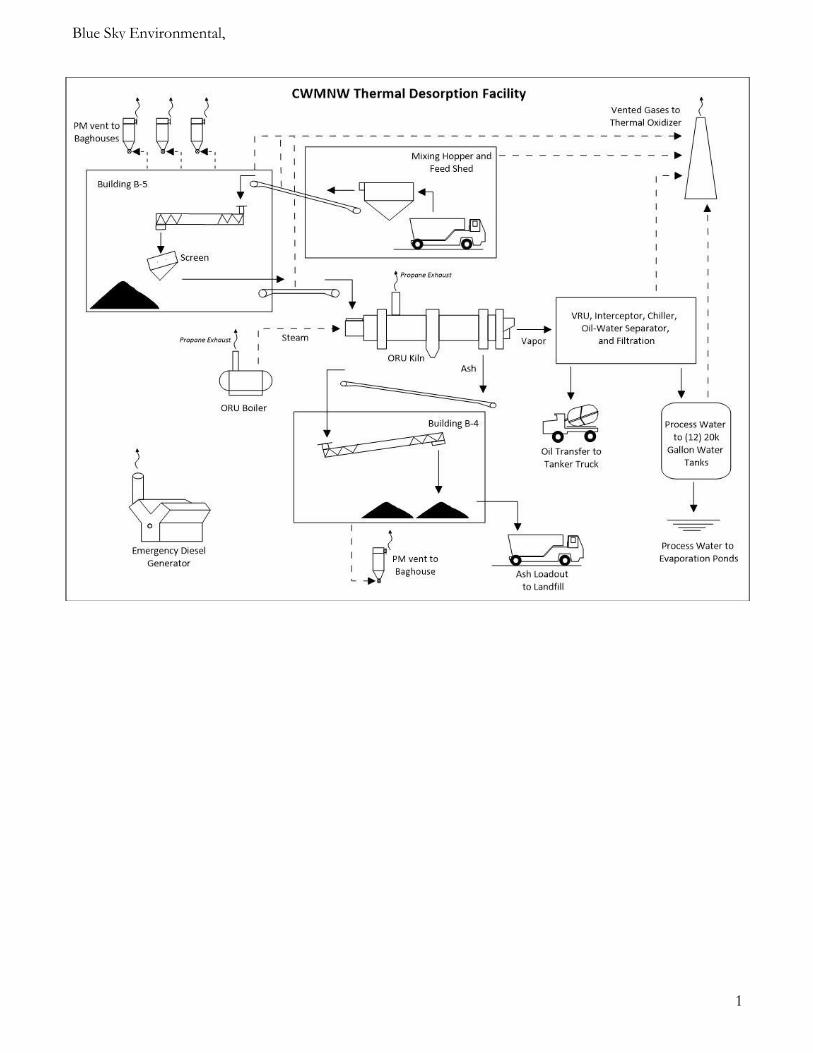
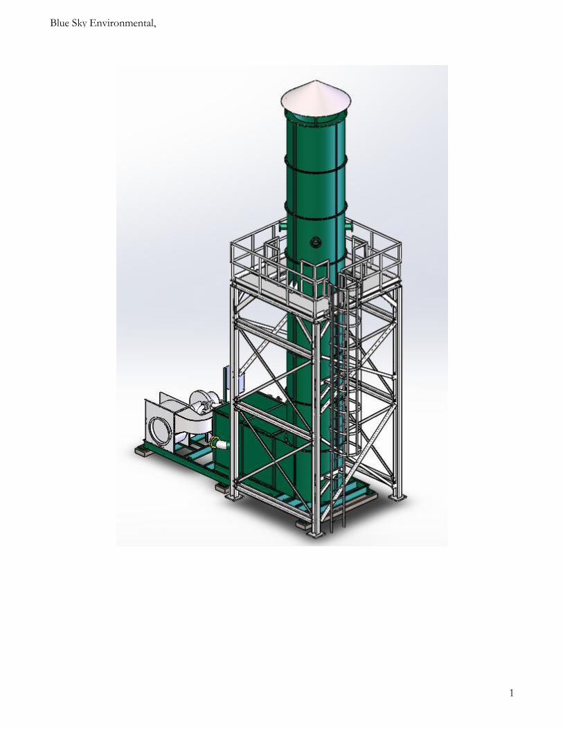
2.0 Emission Source Information The ORU2 process was manufactured by RLC Technologies, Inc., located in Glen Allen, Virginia, and was installed in 2018. The ORU2 processes and recycles refinery tank bottom wastes at a rate of approximately 1.7 tons per hour. These wastes are processed in an indirect fired Rotary Kiln operated at 900-950°F, which is fired with propane. The gases are directed to the Vapor Recovery Unit (VRU, ME-1301) where water is sprayed into the gas stream, followed by a venturi scrubber with demisters to knock out fine particulates and soluble and condensable organic and inorganic gases. The gases proceed through a chiller to further remove moisture and condensable materials, before entering the Thermal Oxidizer Unit (TOU) operated at 1600-1650°F. Ports will be installed at each of the two inlet waste gas streams feeding the TOU (one from the conveyors and hoppers including inside Building B5, and the other from the Rotary Kiln emissions). These ports will be used to measure the inlet organics by U.S. Environmental Protection Agency (EPA) Method 25 and EPA Method TO-15, fixed gases by American Society for Testing and Materials (ASTM) Method 1945 and volumetric flowrate by pitot tube. The inlet gases are close to ambient temperature and will be assumed to be at 100% humidity for moisture determination. No ports currently exist on the TOU stack (~ 60” inner diameter, ID), however plans are underway to provide four 6” diameter ports with a platform, located 5-8 diameters downstream and >2 diameters upstream of the exit, which will require a stack extension and platform construction, which is being designed and will be constructed prior to testing. 3.0 Source Testing Program Description
Test Location No. Runs & Duration Methods Parameters
Stack Gas 3 x 1-hr simultaneously
with isokinetic tests
EPA 1, 2, 4 EPA 3A, 10
EPA 25A/ALT-097
Flowrate & H2O %
CO, CO2, O2 THC, NMHC
Stack Gas 3 x 1-hr Isokinetic EPA 5/26A Filterable Particulates,
Hydrogen Halides (HCl)
Stack Gas 3 x 3 hr Isokinetic EPA 29 Metals -
Sb, AS, Ba, Be, Cd, Cr, Co, Cu, Pb, Mn, Hg, Ni, P, Se, Ag, Tl, Zn,+Al & V

Blue Sky Environmental, Inc
5
Test Location No. Runs & Duration Methods Parameters
Stack Gas 3 x 3 hr Isokinetic EPA 23 Dioxins/Furans & PAH’s
Stack Gas 3 x 3 hr Isokinetic EPA 23 Dioxins/Furans & PAH’s
Stack Gas 3 x 1 hr simultaneously with THC and NMHC
EPA TO-15 Volatile Organic Species
TOU 2 Inlet streams
3 x 1 hr simultaneously with Stack Gas TO-15
EPA TO-15 Volatile Organic Species
TOU 2 Inlet streams
3 x 1 hr simultaneously with Stack Gas THC
and NMHC
EPA 25 & ASTM 1945
NMHC & Fixed Gases
TOU 2 Inlet streams
EPA 1, 2C, 3A or 3C Flowrate %CO, CO2, O2
Solid Feed Material 15 -minute grabs (1-hr
composites)
SW-846 Metals by ICPES 60100B and
7471 for Hg Chlorine, Methods
5050 & 9056A
Metals – Ag, As, Ba, Be, Cd, Cr, Ni, Pb, Sb, Se, Tl, V, Zn, Hg and BTEX
Reporting units
Gases in ppmvd, ppbv PM in gr/dscf
Metals in ug/dscm Dioxins etc in ng/dscm
Operating Parameters
15-min intervals Time, TDU Feed Rate, TOU
Temperature, TDU propane flow rate
Blue Sky Environmental, Inc
6
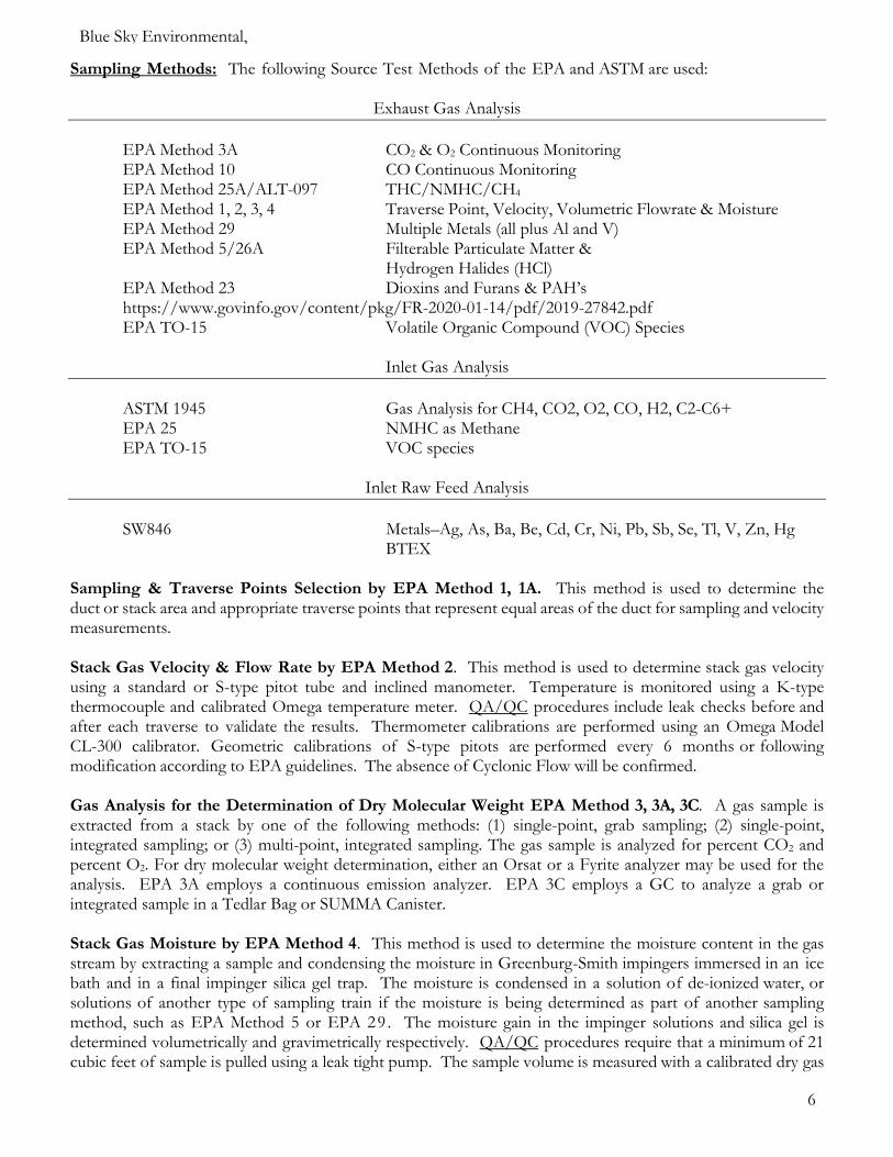
Sampling Methods: The following Source Test Methods of the EPA and ASTM are used:
Exhaust Gas Analysis
EPA Method 3A CO2 & O2 Continuous Monitoring EPA Method 10 CO Continuous Monitoring EPA Method 25A/ALT-097 THC/NMHC/CH4 EPA Method 1, 2, 3, 4 Traverse Point, Velocity, Volumetric Flowrate & Moisture EPA Method 29 Multiple Metals (all plus Al and V) EPA Method 5/26A Filterable Particulate Matter & Hydrogen Halides (HCl) EPA Method 23 Dioxins and Furans & PAH’s https://www.govinfo.gov/content/pkg/FR-2020-01-14/pdf/2019-27842.pdf EPA TO-15 Volatile Organic Compound (VOC) Species
Inlet Gas Analysis
ASTM 1945 Gas Analysis for CH4, CO2, O2, CO, H2, C2-C6+ EPA 25 NMHC as Methane EPA TO-15 VOC species
Inlet Raw Feed Analysis
SW846 Metals–Ag, As, Ba, Be, Cd, Cr, Ni, Pb, Sb, Se, Tl, V, Zn, Hg BTEX
Sampling & Traverse Points Selection by EPA Method 1, 1A. This method is used to determine the duct or stack area and appropriate traverse points that represent equal areas of the duct for sampling and velocity measurements. Stack Gas Velocity & Flow Rate by EPA Method 2. This method is used to determine stack gas velocity using a standard or S-type pitot tube and inclined manometer. Temperature is monitored using a K-type thermocouple and calibrated Omega temperature meter. QA/QC procedures include leak checks before and after each traverse to validate the results. Thermometer calibrations are performed using an Omega Model CL-300 calibrator. Geometric calibrations of S-type pitots are performed every 6 months or following modification according to EPA guidelines. The absence of Cyclonic Flow will be confirmed. Gas Analysis for the Determination of Dry Molecular Weight EPA Method 3, 3A, 3C. A gas sample is extracted from a stack by one of the following methods: (1) single-point, grab sampling; (2) single-point, integrated sampling; or (3) multi-point, integrated sampling. The gas sample is analyzed for percent CO2 and percent O2. For dry molecular weight determination, either an Orsat or a Fyrite analyzer may be used for the analysis. EPA 3A employs a continuous emission analyzer. EPA 3C employs a GC to analyze a grab or integrated sample in a Tedlar Bag or SUMMA Canister. Stack Gas Moisture by EPA Method 4. This method is used to determine the moisture content in the gas stream by extracting a sample and condensing the moisture in Greenburg-Smith impingers immersed in an ice bath and in a final impinger silica gel trap. The moisture is condensed in a solution of de-ionized water, or solutions of another type of sampling train if the moisture is being determined as part of another sampling method, such as EPA Method 5 or EPA 29. The moisture gain in the impinger solutions and silica gel is determined volumetrically and gravimetrically respectively. QA/QC procedures require that a minimum of 21 cubic feet of sample is pulled using a leak tight pump. The sample volume is measured with a calibrated dry gas
Blue Sky Environmental, Inc
7
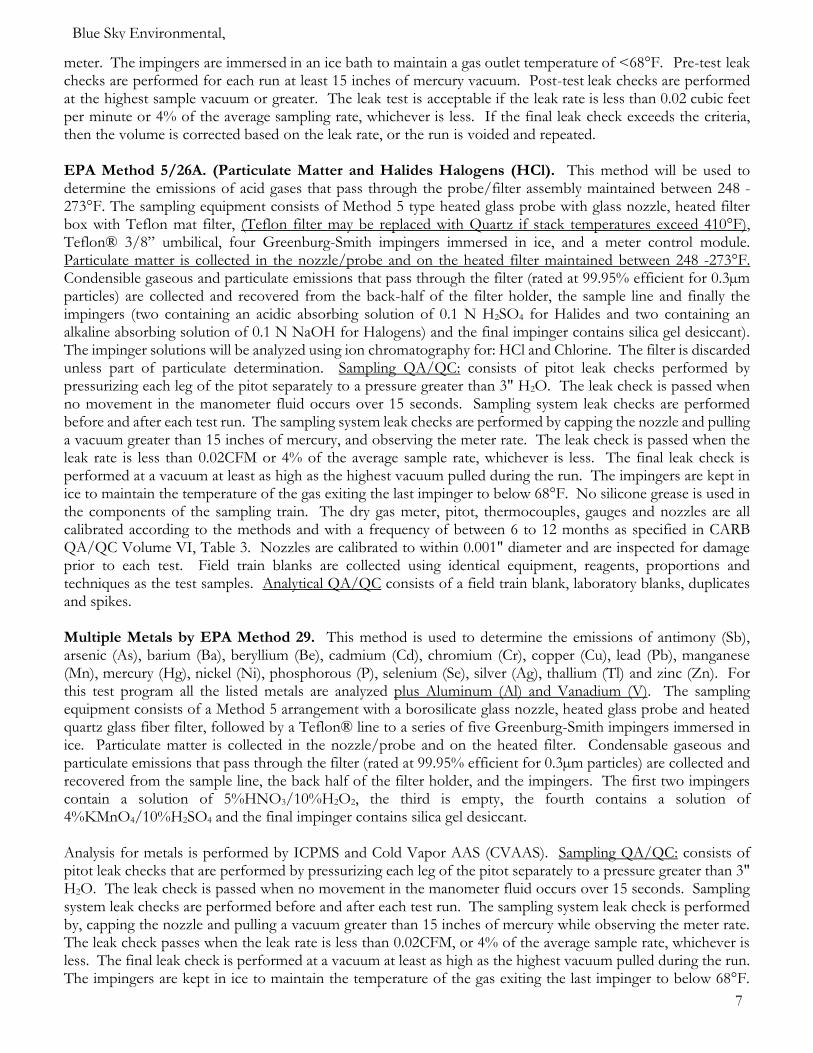
meter. The impingers are immersed in an ice bath to maintain a gas outlet temperature of <68°F. Pre-test leak checks are performed for each run at least 15 inches of mercury vacuum. Post-test leak checks are performed at the highest sample vacuum or greater. The leak test is acceptable if the leak rate is less than 0.02 cubic feet per minute or 4% of the average sampling rate, whichever is less. If the final leak check exceeds the criteria, then the volume is corrected based on the leak rate, or the run is voided and repeated. EPA Method 5/26A. (Particulate Matter and Halides Halogens (HCl). This method will be used to determine the emissions of acid gases that pass through the probe/filter assembly maintained between 248 - 273°F. The sampling equipment consists of Method 5 type heated glass probe with glass nozzle, heated filter box with Teflon mat filter, (Teflon filter may be replaced with Quartz if stack temperatures exceed 410°F), Teflon® 3/8” umbilical, four Greenburg-Smith impingers immersed in ice, and a meter control module. Particulate matter is collected in the nozzle/probe and on the heated filter maintained between 248 -273°F. Condensible gaseous and particulate emissions that pass through the filter (rated at 99.95% efficient for 0.3µm particles) are collected and recovered from the back-half of the filter holder, the sample line and finally the impingers (two containing an acidic absorbing solution of 0.1 N H2SO4 for Halides and two containing an alkaline absorbing solution of 0.1 N NaOH for Halogens) and the final impinger contains silica gel desiccant). The impinger solutions will be analyzed using ion chromatography for: HCl and Chlorine. The filter is discarded unless part of particulate determination. Sampling QA/QC: consists of pitot leak checks performed by pressurizing each leg of the pitot separately to a pressure greater than 3" H2O. The leak check is passed when no movement in the manometer fluid occurs over 15 seconds. Sampling system leak checks are performed before and after each test run. The sampling system leak checks are performed by capping the nozzle and pulling a vacuum greater than 15 inches of mercury, and observing the meter rate. The leak check is passed when the leak rate is less than 0.02CFM or 4% of the average sample rate, whichever is less. The final leak check is performed at a vacuum at least as high as the highest vacuum pulled during the run. The impingers are kept in ice to maintain the temperature of the gas exiting the last impinger to below 68°F. No silicone grease is used in the components of the sampling train. The dry gas meter, pitot, thermocouples, gauges and nozzles are all calibrated according to the methods and with a frequency of between 6 to 12 months as specified in CARB QA/QC Volume VI, Table 3. Nozzles are calibrated to within 0.001" diameter and are inspected for damage prior to each test. Field train blanks are collected using identical equipment, reagents, proportions and techniques as the test samples. Analytical QA/QC consists of a field train blank, laboratory blanks, duplicates and spikes. Multiple Metals by EPA Method 29. This method is used to determine the emissions of antimony (Sb), arsenic (As), barium (Ba), beryllium (Be), cadmium (Cd), chromium (Cr), copper (Cu), lead (Pb), manganese (Mn), mercury (Hg), nickel (Ni), phosphorous (P), selenium (Se), silver (Ag), thallium (Tl) and zinc (Zn). For this test program all the listed metals are analyzed plus Aluminum (Al) and Vanadium (V). The sampling equipment consists of a Method 5 arrangement with a borosilicate glass nozzle, heated glass probe and heated quartz glass fiber filter, followed by a Teflon® line to a series of five Greenburg-Smith impingers immersed in ice. Particulate matter is collected in the nozzle/probe and on the heated filter. Condensable gaseous and particulate emissions that pass through the filter (rated at 99.95% efficient for 0.3µm particles) are collected and recovered from the sample line, the back half of the filter holder, and the impingers. The first two impingers contain a solution of 5%HNO3/10%H2O2, the third is empty, the fourth contains a solution of 4%KMnO4/10%H2SO4 and the final impinger contains silica gel desiccant. Analysis for metals is performed by ICPMS and Cold Vapor AAS (CVAAS). Sampling QA/QC: consists of pitot leak checks that are performed by pressurizing each leg of the pitot separately to a pressure greater than 3" H2O. The leak check is passed when no movement in the manometer fluid occurs over 15 seconds. Sampling system leak checks are performed before and after each test run. The sampling system leak check is performed by, capping the nozzle and pulling a vacuum greater than 15 inches of mercury while observing the meter rate. The leak check passes when the leak rate is less than 0.02CFM, or 4% of the average sample rate, whichever is less. The final leak check is performed at a vacuum at least as high as the highest vacuum pulled during the run. The impingers are kept in ice to maintain the temperature of the gas exiting the last impinger to below 68°F.

Blue Sky Environmental, Inc
8
The acidified KMnO4 solution is prepared fresh daily and is protected from daylight. During testing the solution is observed to detect any discoloration due to mercury. No silicone grease is used in the components of the sampling train. The dry gas meter, pitot, thermocouples, gauges and nozzles are all calibrated according to the methods and with a frequency of between 6 to 12 months as specified in CARB QA/QC Volume VI, Table 3. Nozzles are calibrated in the field to within 0.001" diameter and are inspected for damage prior to each test. Field train blanks are collected using identical equipment, reagents, proportions and techniques as the test samples. Analytical QA/QC consists of a field train blank, laboratory blanks, duplicates and spikes. Hexavalent Chromium Methods for Hexavalent Chromium (CRVI or Cr6+) have not been validated by the EPA for temperatures above 300°F. Robin Segall and staff (EPA-RTP) do not advise using this method and acknowledge the technical issues and unknown chemical states that performing Method 0061 at flare temperatures would difficult to impossible to consider, see Appendix G email correspondence. Robin’s advice was to use EPA 29 to measure total Chromium and base the Hexavalent Chromium on that. Published Scientific study by the National Risk Management Research Laboratory in RTP of the effect of high temperature incineration and flaring specifically address the formation of Hexavalent Chromium at high temperature and clearly indicate that 2% of Total Chromium is converted into Hexavalent. Using 2% of the Total Chromium is therefore the practical and scientifically supported basis for performing the CRVI risk assessment. https://cfpub.epa.gov/si/si_public_record_report.cfm?Lab=NRMRL&dirEntryId=128563 EPA Method 23 Dioxins/Furans & Polycyclic Aromatic Hydrocarbons (PAHs) is used to determine the emissions of polychlorinated dibenzo-p-dioxins (PCDD’s) and polychlorinated dibenzofurans (PCDFs). The sampling equipment consists of a glass nozzle, a Stainless Steel sheathed heated glass-lined probe, heated filter box and filter holder with teflon-coated, toluene-rinsed, glass-fiber filter, followed by a Teflon® line to a condenser and XAD sorbent module that sits directly on-top of the first of four modified Greenburg-Smith impingers. The first impinger (optional) has a short stem and is empty, the second and third contain 100 ml each of De-Ionized water, and the fourth is empty. A fifth impinger contains 200-plus gm of silica gel to remove any remaining moisture. The sample is drawn through the sample train using a vacuum pump and the volume is measured by a dry gas meter in an isokinetic metering control module. Sampling is performed isokinetically. Sampling QA/QC: consists of pitot leak checks which are performed by pressurizing each leg of the pitot separately to a pressure greater than 3" H2O. The leak check is passed when no movement in the manometer fluid occurs over 15 seconds. Sampling system leak checks are performed before and after each test run. The sampling system leak checks are performed by capping the nozzle and pulling a vacuum greater than 15 inches of mercury, and observing the meter rate. The leak check is passed when the leak rate is less than 0.02CFM or 4% of the average sample rate, whichever is less. The final leak check is performed at a vacuum at least as high as the highest vacuum pulled during the run. The impingers are kept in ice to maintain the temperature of the gas exiting the last impinger to below 68°F. No silicone grease is used in the components of the sampling train. Sample recovery is performed in a clean enclosed area or at the laboratory. The nozzle/probe sample is recovered with acetone, then methylene chloride and finally a toluene rinse. The filter is carefully removed and placed in a labeled petri-dish. The transfer line between the filter and condenser, the condenser and the first impinger are rinsed three times, first with acetone followed by toluene. The sorbent module is capped. The volume of the contents of the first, second and third impingers are measured or weighed for moisture determination and are saved and rinsed with acetone and Toluene for PAH analysis. The silica gel is recovered and weighed. Equipment QA/QC includes the following: The dry gas meter, pitot, thermocouples, gauges and nozzles are all calibrated according to the methods and with a frequency of between 6 to 12 months as specified in CARB QA/QC Volume VI, Table 3. Nozzles are calibrated to within 0.001" diameter and are inspected for damage
Blue Sky Environmental, Inc
9
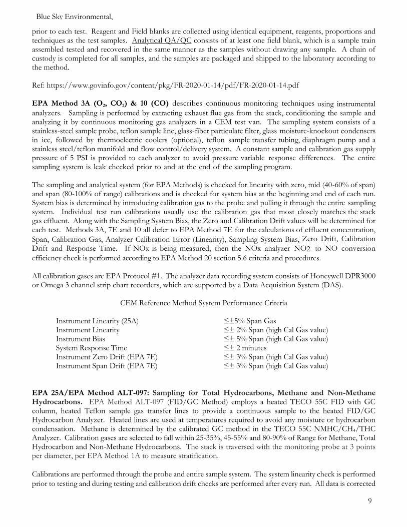
prior to each test. Reagent and Field blanks are collected using identical equipment, reagents, proportions and techniques as the test samples. Analytical QA/QC consists of at least one field blank, which is a sample train assembled tested and recovered in the same manner as the samples without drawing any sample. A chain of custody is completed for all samples, and the samples are packaged and shipped to the laboratory according to the method. Ref: https://www.govinfo.gov/content/pkg/FR-2020-01-14/pdf/FR-2020-01-14.pdf EPA Method 3A (O2, CO2) & 10 (CO) describes continuous monitoring techniques using instrumental analyzers. Sampling is performed by extracting exhaust flue gas from the stack, conditioning the sample and analyzing it by continuous monitoring gas analyzers in a CEM test van. The sampling system consists of a stainless-steel sample probe, teflon sample line, glass-fiber particulate filter, glass moisture-knockout condensers in ice, followed by thermoelectric coolers (optional), teflon sample transfer tubing, diaphragm pump and a stainless steel/teflon manifold and flow control/delivery system. A constant sample and calibration gas supply pressure of 5 PSI is provided to each analyzer to avoid pressure variable response differences. The entire sampling system is leak checked prior to and at the end of the sampling program. The sampling and analytical system (for EPA Methods) is checked for linearity with zero, mid (40-60% of span) and span (80-100% of range) calibrations and is checked for system bias at the beginning and end of each run. System bias is determined by introducing calibration gas to the probe and pulling it through the entire sampling system. Individual test run calibrations usually use the calibration gas that most closely matches the stack gas effluent. Along with the Sampling System Bias, the Zero and Calibration Drift values will be determined for each test. Methods 3A, 7E and 10 all defer to EPA Method 7E for the calculations of effluent concentration,
Span, Calibration Gas, Analyzer Calibration Error (Linearity), Sampling System Bias, Zero Drift, Calibration
Drift and Response Time. If NOx is being measured, then the NOx analyzer NO2 to NO conversion
efficiency check is performed according to EPA Method 20 section 5.6 criteria and procedures. All calibration gases are EPA Protocol #1. The analyzer data recording system consists of Honeywell DPR3000 or Omega 3 channel strip chart recorders, which are supported by a Data Acquisition System (DAS).
CEM Reference Method System Performance Criteria
Instrument Linearity (25A) ≤±5% Span Gas Instrument Linearity ≤± 2% Span (high Cal Gas value) Instrument Bias ≤± 5% Span (high Cal Gas value) System Response Time ≤± 2 minutes Instrument Zero Drift (EPA 7E) ≤± 3% Span (high Cal Gas value) Instrument Span Drift (EPA 7E) ≤± 3% Span (high Cal Gas value)
EPA 25A/EPA Method ALT-097: Sampling for Total Hydrocarbons, Methane and Non-Methane Hydrocarbons. EPA Method ALT-097 (FID/GC Method) employs a heated TECO 55C FID with GC column, heated Teflon sample gas transfer lines to provide a continuous sample to the heated FID/GC Hydrocarbon Analyzer. Heated lines are used at temperatures required to avoid any moisture or hydrocarbon condensation. Methane is determined by the calibrated GC method in the TECO 55C NMHC/CH4/THC Analyzer. Calibration gases are selected to fall within 25-35%, 45-55% and 80-90% of Range for Methane, Total Hydrocarbon and Non-Methane Hydrocarbons. The stack is traversed with the monitoring probe at 3 points per diameter, per EPA Method 1A to measure stratification.
Calibrations are performed through the probe and entire sample system. The system linearity check is performed
prior to testing and during testing and calibration drift checks are performed after every run. All data is corrected
Blue Sky Environmental, Inc
10
according to EPA Method 25A.
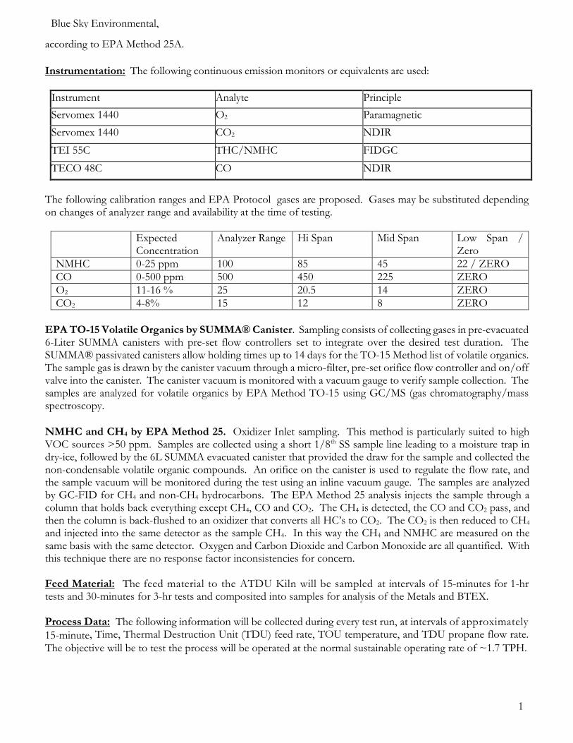
Instrumentation: The following continuous emission monitors or equivalents are used:
Instrument Analyte Principle
Servomex 1440 O2 Paramagnetic
Servomex 1440 CO2 NDIR
TEI 55C THC/NMHC FIDGC
TECO 48C CO NDIR
The following calibration ranges and EPA Protocol gases are proposed. Gases may be substituted depending on changes of analyzer range and availability at the time of testing.
Expected Concentration
Analyzer Range Hi Span
Mid Span Low Span / Zero
NMHC 0-25 ppm 100 85 45 22 / ZERO
CO 0-500 ppm 500 450 225 ZERO
O2 11-16 % 25 20.5 14 ZERO
CO2 4-8% 15 12 8 ZERO
EPA TO-15 Volatile Organics by SUMMA® Canister. Sampling consists of collecting gases in pre-evacuated 6-Liter SUMMA canisters with pre-set flow controllers set to integrate over the desired test duration. The SUMMA® passivated canisters allow holding times up to 14 days for the TO-15 Method list of volatile organics. The sample gas is drawn by the canister vacuum through a micro-filter, pre-set orifice flow controller and on/off valve into the canister. The canister vacuum is monitored with a vacuum gauge to verify sample collection. The samples are analyzed for volatile organics by EPA Method TO-15 using GC/MS (gas chromatography/mass spectroscopy.
NMHC and CH4 by EPA Method 25. Oxidizer Inlet sampling. This method is particularly suited to high VOC sources >50 ppm. Samples are collected using a short 1/8th SS sample line leading to a moisture trap in dry-ice, followed by the 6L SUMMA evacuated canister that provided the draw for the sample and collected the non-condensable volatile organic compounds. An orifice on the canister is used to regulate the flow rate, and the sample vacuum will be monitored during the test using an inline vacuum gauge. The samples are analyzed by GC-FID for CH4 and non-CH4 hydrocarbons. The EPA Method 25 analysis injects the sample through a column that holds back everything except CH4, CO and CO2. The CH4 is detected, the CO and CO2 pass, and then the column is back-flushed to an oxidizer that converts all HC’s to CO2. The CO2 is then reduced to CH4 and injected into the same detector as the sample CH4. In this way the CH4 and NMHC are measured on the same basis with the same detector. Oxygen and Carbon Dioxide and Carbon Monoxide are all quantified. With this technique there are no response factor inconsistencies for concern. Feed Material: The feed material to the ATDU Kiln will be sampled at intervals of 15-minutes for 1-hr tests and 30-minutes for 3-hr tests and composited into samples for analysis of the Metals and BTEX. Process Data: The following information will be collected during every test run, at intervals of approximately
15-minute, Time, Thermal Destruction Unit (TDU) feed rate, TOU temperature, and TDU propane flow rate.
The objective will be to test the process will be operated at the normal sustainable operating rate of ~1.7 TPH.
Blue Sky Environmental, Inc
11
4.0 Reporting, QA & QC Procedures The referenced sampling methods describe the QA/QC procedures and documentation that will be followed in implementing and executing this Source Test Program. Responsibility for all QA/QC is that of the onsite Project Manager. The Project Manager will be Chuck Arrivas, supported by Jeramie Richardson, Adam Ashlin and Guy Worthington. Mr. Worthington has over 33 years of experience in source emissions testing, most of that time in the position of a senior Project Manager. Jeramie Richardson (QSTi), Adam Ashlin and Chuck Arrivas (QSTi) all have greater than 12 years’ experience each. All Labs shall be Accredited and ultimately ODEQ approved. The specific Labs have yet to be finalized. Probable Labs are Chester (Metals), Bureau Veritas (Metals & M23), Vista (M23) and Atmospheric Analysis and Consulting (Organics including 25, 25C, TO-15). Data collection, reduction and reporting are performed using Word and Excel software, and HP basic programmable calculators. The report will contain all raw data and calculations, with equations shown. The final report is normally submitted within 4 weeks of the test completion, or 2 weeks following the completion of any laboratory analysis. The ODEQ has granted the reporting period to be extended from 30 days to 60 days for this project. A ODEQ Source Test Audit Report (STAR) for all applicable test Methods will be prepared to accompany the submittal of the final source test report. Three copies of the report are submitted to the client, and it is their responsibility to forward a copy to the appropriate agency.

Blue Sky Environmental, Inc
12
Expected Timeline Day 0 Setup Flare Gas Sampling & Analysis Day 1 3 x 1hr M5/26A + 3 x 1 hr TO-15 + 3 x 1hr THC, O2, CO, CO2 Day 2 1 x 3hr M29 + 1 x 3hr M23 + 3 x O2 and CO2 Day 3 2 x 3hr M29 + 2 x 3hr M23 + 3 x O2 and CO2 Inlet Gas Analysis On both the 4” and 6” inlets Day 1 3 x 1 hr EPA 25 for NMHC and EPA TO-15 VOC species Day 1 3 x 1 hr ASTM 1945 for Gas Analysis for CH4, CO2, O2, CO, H2, C2-C6+ Methods 1-4 Day 2 1 x 1 hr ASTM 1945 for Gas Analysis for CH4, CO2, O2, CO, H2, C2-C6+ Methods 1-4 Day 3 2 x 1 hr ASTM 1945 for Gas Analysis for CH4, CO2, O2, CO, H2, C2-C6+ Methods 1-4 Inlet Feed Analysis Metals – Ag, As, Ba, Be, Cd, Cr, Ni, Pb, Sb, Se, Tl, V, Zn, Hg and BTEX
5.0 Plant Entry and Safety For this site, personnel shall be OSHA Hazwoper trained to work within the area. All visitors to site must sign in at the office trailer and complete a safety orientation be trained on basic procedures for the facility. While on site all personnel must where appropriate P P E safety gear as needed including hard-hat, safety glasses, safety shoes and appropriate clothing (suits), respirators etc. All work performed on site must be approved by site manager and documented in a work permit. If there are any questions concerning this Source Test Plan, please contact Guy Worthington at 510-525-1261 or 510-508-3469 or Chuck Arrivas at 925-338-4875. Submitted by, Guy Worthington Appendix A Process Flow Diagram Appendix B Stack and Port Location & Configuration Appendix C Sample Detection Limits, lbs/hr Appendix D Sample TO-15 Analysis List Appendix E ALT 097 (modification to 25A) for flares Appendix F M23 sample and lab analysis chart Appendix G Robin Segall and staff (EPA-RTP) emails
Blue Sky Environmental, Inc
13
APPENDIX A
Process Flow Diagram
Blue Sky Environmental, Inc
14

15
Blue Sky Environmental, Inc
APPENDIX B
Stack and Port Location Configuration
16
Blue Sky Environmental, Inc

17
Blue Sky Environmental, Inc
Inlet gas streams

18
Blue Sky Environmental, Inc
Top Inlet line ~ 6”
Lower Inlet Line ~4”

19
Blue Sky Environmental, Inc
APPENDIX C Sample Detection Limits, lbs/hr

20
Blue Sky Environmental, Inc

21
Blue Sky Environmental, Inc
APPENDIX D Sample TO-15 Analysis List

22
Blue Sky Environmental, Inc

23
Blue Sky Environmental, Inc

24
Blue Sky Environmental, Inc
APPENDIX E ALT 097 (modification to 25A) for flares
25
Blue Sky Environmental, Inc

26
Blue Sky Environmental, Inc

27
Blue Sky Environmental, Inc
APPENDIX F M23 sample and lab analysis chart

28
Blue Sky Environmental, Inc

29
Blue Sky Environmental, Inc
APPENDIX G Robin Segall and staff (EPA-RTP) emails

30
Blue Sky Environmental, Inc
----- Forwarded Message ----- From: Dewees, Jason <[email protected]> To: Segall, Robin <[email protected]>; [email protected] <[email protected]> Cc: Shappley, Ned <[email protected]> Sent: Wednesday, March 18, 2020, 1:21:24 PM PDT Subject: RE: M0061 Testing at 1600 Degrees F
I agree. I don’t see a scenario that the 0061 methodology could be adapted for those temperatures.
Jason
From: Segall, Robin <[email protected]> Sent: Wednesday, March 18, 2020 4:18 PM To: [email protected] Cc: Dewees, Jason <[email protected]>; Shappley, Ned <[email protected]> Subject: M0061 Testing at 1600 Degrees F
Guy,
After our discussion Monday, I went back to some past emails I had on M0061 testing at high temperatures. Based on those, I think it may be difficult to impossible to test at temperatures around 1600 F. You would have to use an air cooled probe and be able to get the gas coming into the probe cooled down enough so as not to vaporize the recirculating solution. Obviously keeping the recirculating solution as cold as possible would also be key. If you sampled at a single point close to the stack wall that would give you more probe outside the stack and help with cooling. As we discussed, you would need a quartz probe and likely teflon-lined impingers.
I am copying two of my colleagues that have conducted M0061 several times in the past and they may have some additional insights or may be able to confirm if it is not possible to run the method at these temperatures,
Robin
.
Robin R. Segall Senior Environmental Scientist
Measurement Technology Group|Office of Air Quality Planning & Standards
US EPA (E143-02)|Research Triangle Park, NC 27711
O: 919-541-0893
F: 919-541-0615