blown film extrusion technology presented by general extrusion technology (get)
TRANSCRIPT

Blown Film Extrusion Technology
Presented byGeneral Extrusion Technology
(GET)


Blown Film Extrusion Technology
• The future trend of extrusion technology is high speed, high output, less energy consumption at competitive cost
• The following slides will provide you an overview of blown film extrusion technologies
• Some of those technologies are proven and some of them represent the latest development from General Extrusion Technology Ltd.
• The information contained in this presentation may be proprietary, confidential and privileged, and, therefore protected from disclosure

Blown Film Extrusion Technology
• GET partners with some world best component/system suppliers

Blown Film Extrusion Technology• GET partners with some world best component/system
suppliers
Complete line control, gauge system, IBC control,
Germany
Extruder gearbox, Germany
Extruder high torque motor, Germany
AC motor and drive, ABB China
Gear motor for extruder, winder, haul-off and bubble cage,
SEW China

Blown Film Extrusion Technology• GET partners with some world best component/system
suppliers
PLC control system for winder, Autria
All pneumatic web guide system, USA
Control cabinet, low voltage components, Schneider China
Solid state relay switch, Swiss
Control cabinet, Rittal China

Blown Film Extrusion Technology• GET partners with some world best component/system
suppliers
Bearing for all rollers, NSK China
Busbar system, Germany
Brush spreader roller horizontal haul-off, Germany
Heater band, Watlow China
Melt pressure transducer, USA
Barrel and screw, USA
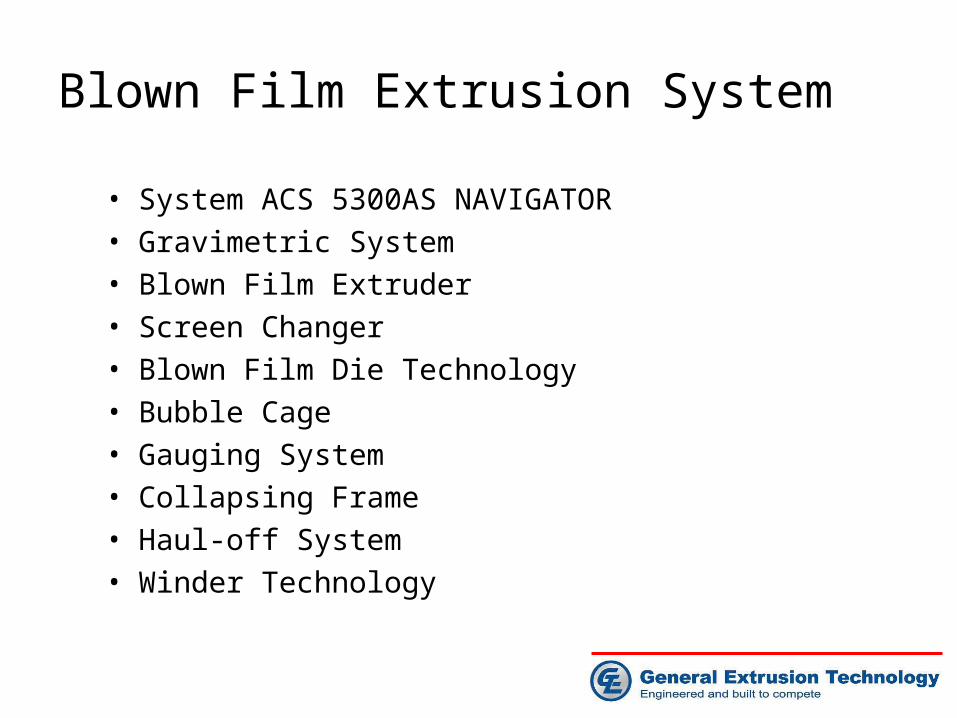
Blown Film Extrusion System
• System ACS 5300AS NAVIGATOR
• Gravimetric System
• Blown Film Extruder
• Screen Changer
• Blown Film Die Technology
• Bubble Cage
• Gauging System
• Collapsing Frame
• Haul-off System
• Winder Technology

System ACS 5300AS NAVIGATOR
19” Color touch screen

System ACS 5300AS NAVIGATOR
• System ACS NAVIGATOR control principle• Plant wide control concept• Modular structure• Machine control NAVIGATOR• Temperature control
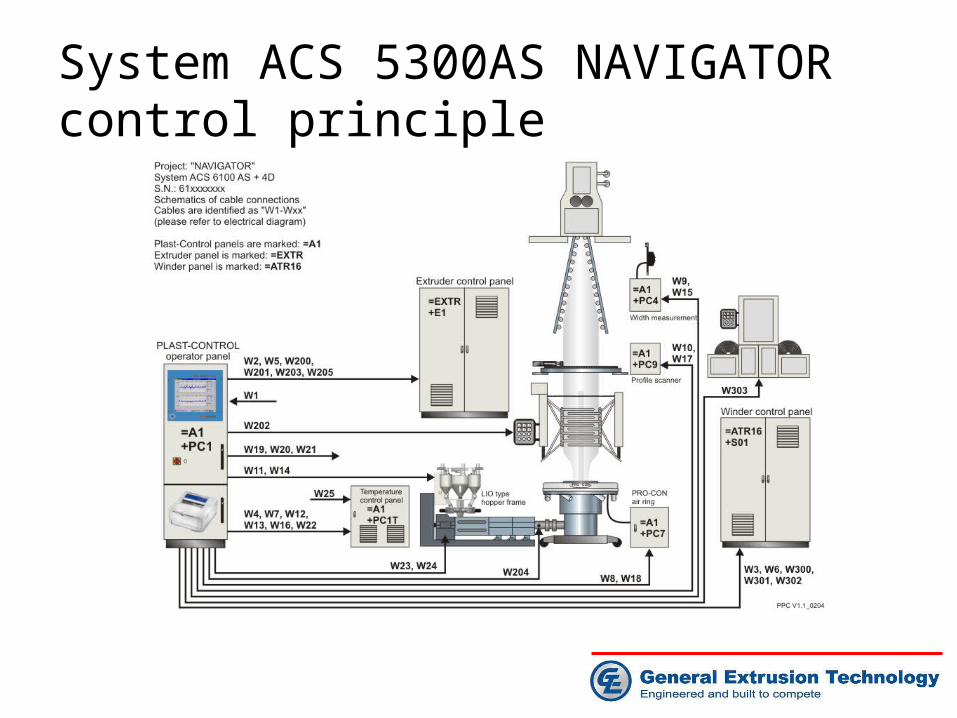
System ACS 5300AS NAVIGATOR control principle

Modem connection
Printer package
Office network link
Plant wide control concept

Modular structure

Base module
Access to each individual system in the network

Base module
Hall-wide status with efficiency and summary information

Base module
Alarm report with trace function

Expansion module of historical trend
Historical trace of process data

Expansion module of historical profile trend
Historical trace of profile data

Expansion module of report data base
Handling of summary, shift and week reports
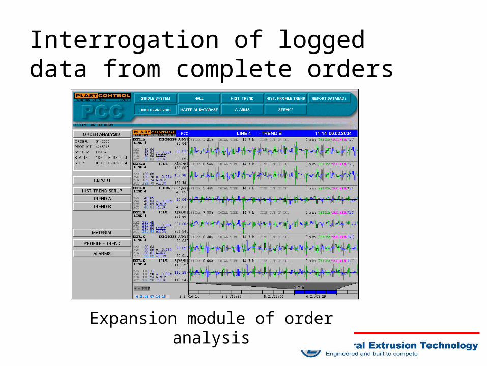
Expansion module of order analysisExpansion module of order analysis
Interrogation of logged data from complete orders

Expansion module of material data base
Complete material data base management

Machine control NAVIGATOR
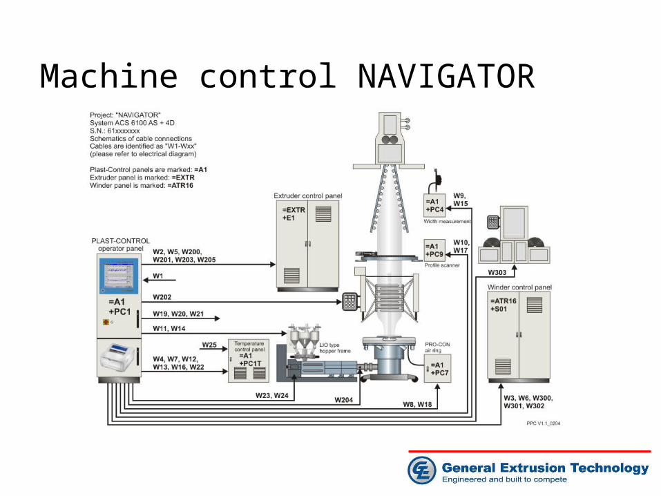
Machine control NAVIGATOR

Machine control NAVIGATOR

Temperature control

Temperature control

Machine control NAVIGATOR
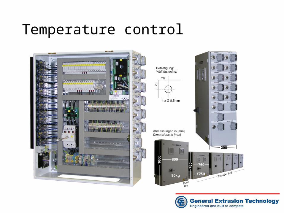
Temperature control

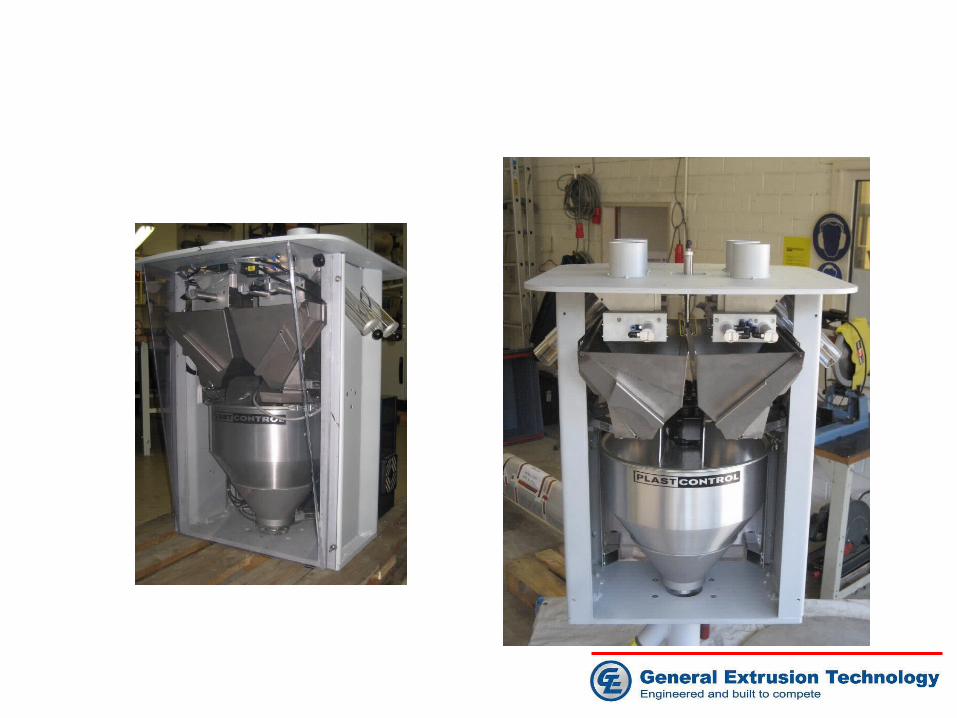
Gravimetric batch blending system
•Plast Control batch blender PB422•Mechanical advantages•Weighing hopper concept•Material conveyor PCH400/PCH800•Pre-filter PCP 500

Gravimetric system advantages
• Rugged mechanical design with easy refill possibility• Weighing device completely tested and calibrated• Density dependent hopper refill• Precise summing even during order changes• Easy understandable material conveying with clear text
messages• Integration into existing central conveying systems• Overfill detection (e.g. after manual refill)• Fast thruput cycles• Intelligent error handling checks operator errors or mechanical
vibrations• Synchronized ramping of each material component• Unified hopper sizes• Unified load cell types for 400 g/h up to 650 kg/h

Material viewing glass
simple cleaning
Quick change attachment for dosing screws Material outlet
Manual slide valve
Rugged design
Manual refill
Mechanical advantages
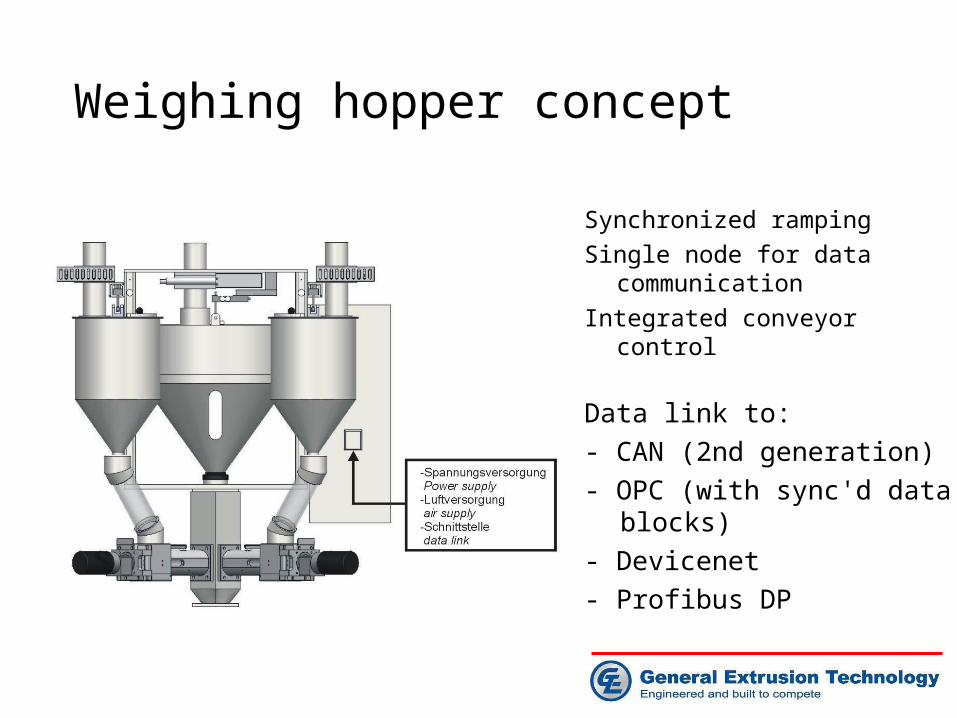
Weighing hopper concept
Synchronized ramping
Single node for data communication
Integrated conveyor control
Data link to:
- CAN (2nd generation)
- OPC (with sync'd data blocks)
- Devicenet
- Profibus DP

Material conveyor PCH400/PCH800

Material conveyor PCH400/PCH800
1) The metal filter is accessible without moving or disconnecting the hoses - Hoses don‘t get bent and leak
2) Variable position of connectors - each connector can be positioned independently
3) Each electrical function with status LED- LED display of material demand- LED display of vacuum status- Optional LED display demand sensor- Optional LED display full sensor
4) Optional viewing glasses in the area of material flap - Operator can always check for sufficient material- Fast service diagnosis

Material conveyor

Pre-filter PCP 500

Blown Film Extruder
•Direct drive with torque motor(gearless)•Traditional drive motor with gearbox•Screw and Barrel Technology•Barrel cooling system
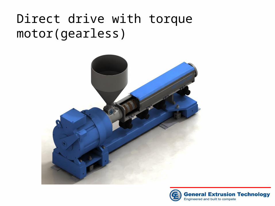
Direct drive with torque motor(gearless)

Torque motor benefits
• 10-20% less energy than a DC motor; 5-10% less energy than a AC motor
• High torque capability permits higher outputs
• Virtually no vibration or noise and need no maintenance
• Water-cooled and dust-free and use less oil-advantages for medical and food-packaging films
• Compact size, an advantage for coextrusion
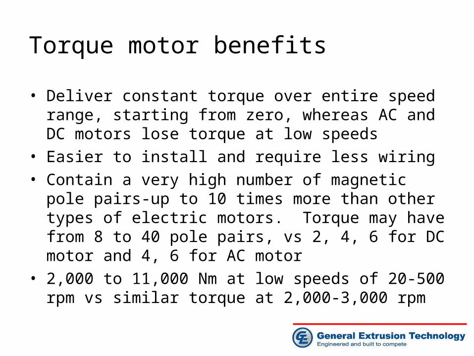
Torque motor benefits
• Deliver constant torque over entire speed range, starting from zero, whereas AC and DC motors lose torque at low speeds
• Easier to install and require less wiring• Contain a very high number of magnetic pole pairs-up to
10 times more than other types of electric motors. Torque may have from 8 to 40 pole pairs, vs 2, 4, 6 for DC motor and 4, 6 for AC motor
• 2,000 to 11,000 Nm at low speeds of 20-500 rpm vs similar torque at 2,000-3,000 rpm
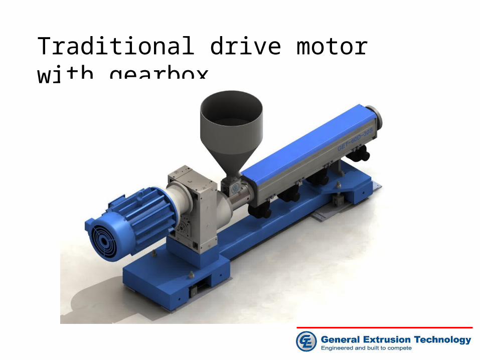
Traditional drive motor with gearbox
Traditional drive motor with gearbox
• Directly coupled motor and gearbox for energy and
space efficiency
• Compact design with high power rating
• Centerline to match application
• Full length steel base frame
• Maximum rigidity maintains alignment
• Minimize screw wear

Screw and Barrel Technology
• Some of the most important requirements are• Processability of mixtures with different sized and different
shaped granules• High plastificating performance• Gentle but complete plastification • Good melt homogeneity• Controlled melt temperatures• Minimal change in the material through degradation or
crosslinking• High level of versatility: ability to process a broad selection of
raw materials with a wide range of throughput rates• Low performance-related investment and operating cost

Smooth bore barrel• Smooth bore barrel is largely
used by extruder builder in USA, even as today
• Good for high-melt-temperature polymers, like nylon, PET, PC and fluoropolymers
• Broad range of polymers• Ability to introduce fluff
regrind• Not suitable for HMW-HDPE• Smooth bore extruder
operates against die pressure and is difficult to maintain desired melt temperature as screw speed increase to raise output

Grooved feed barrel• Grooved bore debuted in
Europe in the 1950s• Produce 20-40% higher
output than smooth bore extruder
• Required for HMW-HDPE• Nearly constant pumping
rate regardless of head pressure
• Lower melt temperature• EVOH & nylon pellets must
be lubricated• Lower rate on soft pellets,
like TPU, softer metallocene polymers
• Not suitable for large volume fluff regrind

Barrier screw for smooth bore barrel
• Deep screw has colder melt, but less mixing, medium screw has best versatility, shallow screw has best mixing, but higher melt temperature
• Maddock mixer is used to improve melt quality• Nylon and EVOH can be processed on the same screw
Metering sectionMetering section Barrier sectionBarrier section Feed sectionFeed section

Barrier screw for grooved bore barrel
• Good dispersive/distributive mixing effect• Heat transfer to the barrel• Low pressure loss• Effective separation of solids from melt• High homogenizing effect• Good control of melt temperature• Clear pressure build-up• Melt throughput geared to homogenizing capacity• Low pressure level• Low torque • Reduced wear and tear
Homogenizing sectionHomogenizing section Barrier sectionBarrier section Feed sectionFeed section

Barrier screw for grooved bore barrel•Barrier screw with homogenizing elements•Barrier screw with homogenizing elements
Rhomboid mixing element
Spiral shearing element

Barrel cooling system
Barrel cooling system design conceptBarrel cooling system design concept
BarrelBarrel
BlowerBlower
Heater band
Heater band
Cooling air flowCooling air flow

Barrel cooling system
• The heat exchange surface area between the barrel and the cooling air flow is critical for the cooling efficiency
• GET’s cooling system is designed for high speed extrusion with intensive cooling• Finned aluminum heat sink for intensive cooling• Finned ceramic heater band for intensive heating and cooling

Barrel cooling system• GET’s innovative design Patent pending

Barrel cooling system• Finned ceramic heater
and aluminum heat sink• Heating capacity up to
7w/cm2 max• Much more cooling
surface than traditional heater band
• Extruded structure aluminum shroud cover filled foamed asbestos to prevent energy loss

Barrel cooling system

Choose a right solution
• Production complexity and investment cost defines the solutions to be used
• A modular cooling element is preferred, which can be adjusted to different barrel diameter and section length relatively easily
• For best control of melt temperature, different cooling system may require for different temperature zone

Screen changer
• The new manual screen changer addresses several problems of the older design. It offers:
• Easy access to the screens by swinging them out completely
• Full 360 degrees circular heaters (without the half-moon cut-outs)
• Less space requirements because of the ratchet type handle
• No need for an additional flange since it mounts directly onto the barrel flange
• Easy removal of the complete unit because it is bolted from the front
Old designOld design
GET new designGET new design

Blown film die system
•Blown film die technology•Air ring technology•Air ring cooling and die cart•Internal bubble cooling(IBC) system

Blown film die system
Single air ring die system Double stack air ring die system

Blown film die system
IBC cooling unit Dual lip air ring
Blown film die IBC air in/out
Die cart Air ring air supply

Blown film die technology• Spiral mandrel die
Sizing ring
Die cart
Die pin
Out layer
Middle layer
Inner layer
Melt feed block Heater band
Die adjustment plate
Air supply
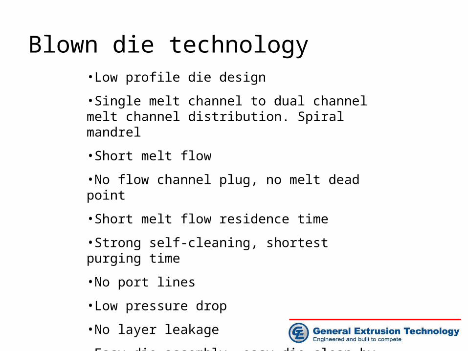
Blown die technology•Low profile die design
•Single melt channel to dual channel melt channel distribution. Spiral mandrel
•Short melt flow
•No flow channel plug, no melt dead point
•Short melt flow residence time
•Strong self-cleaning, shortest purging time
•No port lines
•Low pressure drop
•No layer leakage
•Easy die assembly, easy die clean by customer

Blown die technology• Single to dual melt distribution and spiral mandrel die
Spiral mandrel melt flow channel
Binary pre-distribution)

Simulation of 400 mm 3-layer die
• Material: LDPE, FD0274, Qatar, MI: 2.4• Output: 500 kg/h• Temperature:=210 ℃

400 mm 3-layer blown film die melt flow FEA simulation• Resin: LDPE, FD0274, Qatar, MI: 2.4;• Output: 500 kg/h; Temp:210 ℃

Simulation of the inner layer
Uniform
pressure
distribution in
the die
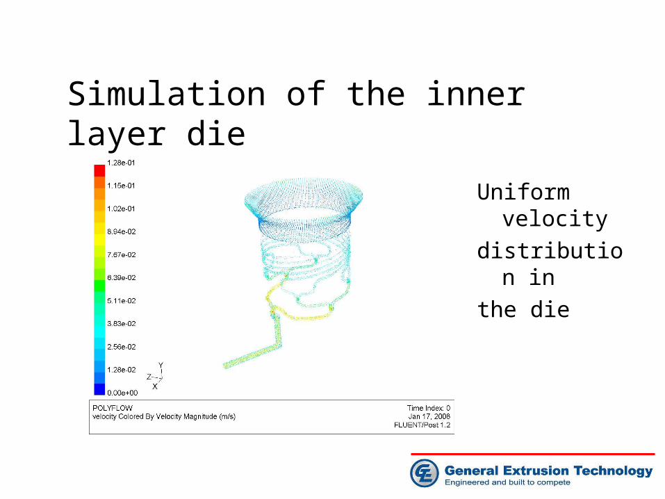
Uniform velocity
distribution in
the die
Simulation of the inner layer die

Simulation of middle layer
Uniform
pressure
distribution in
the die

• Uniform velocity distribution in the die
Simulation of middle layer

Uniform pressure
distribution in the
die
Simulation of outer layer

• Uniform velocity distribution in the die
Simulation of outer layer

Air ring technology
• External bubble cooling and forming• Dual lip air ring type• Perforated chimney dual lip air ring• Double stack air ring• Internal bubble cooling(IBC) system

Air ring technology
• External bubble cooling and bubble forming theory
Venturi effect:
When an air flows through a constricted area its speed increases
and pressure drops
Venturi effect:
When an air flows through a constricted area its speed increases
and pressure drops

Air ring technology
• External bubble cooling and bubble forming
•Coanda effect:
A free air jet emerging from a nozzle will tend to “attach”
itself and flow along an inclined or offset nearby surface(flat or curved)
•Coanda effect:
A free air jet emerging from a nozzle will tend to “attach”
itself and flow along an inclined or offset nearby surface(flat or curved)

Air ring technology
Cooling air flow around
a HDPE bubble
Leftside air flow: 25 lt/s
Rightside air flow: 12 lt/s
Cooling air flow around
a HDPE bubble
Leftside air flow: 25 lt/s
Rightside air flow: 12 lt/s
• External bubble cooling simulation

Air ring technology
Cooling air flow(12 lt/s)
Around a LLDPE bubble
for different adjusting
air ring setup
Left side: low position
Rightside: high position
Cooling air flow(12 lt/s)
Around a LLDPE bubble
for different adjusting
air ring setup
Left side: low position
Rightside: high position
• External bubble cooling simulation

Air ring technology
Heat transfer coefficient profile at high and low positions of adjustable
air ring for LLDPE bubble shape
Heat transfer coefficient profile at high and low positions of adjustable
air ring for LLDPE bubble shape
Coanda effect
greatly influences
the heat transfer
capability of the
cooling are and
stability of the bubble
Coanda effect
greatly influences
the heat transfer
capability of the
cooling are and
stability of the bubble
• External bubble cooling simulation

Air ring technology
• Dual lip air ring type
Dual-lip air rings come in three types that are adjusted by iris, perforated chimney, or stabilizer rings. Each requires different adjustments for each bubble problem.Dual-lip air rings come in three types that are adjusted by iris, perforated chimney, or stabilizer rings. Each requires different adjustments for each bubble problem.

Air ring technology• Perforated Chimney type dual lip air ring
Forming cone and chimney manual adjustment
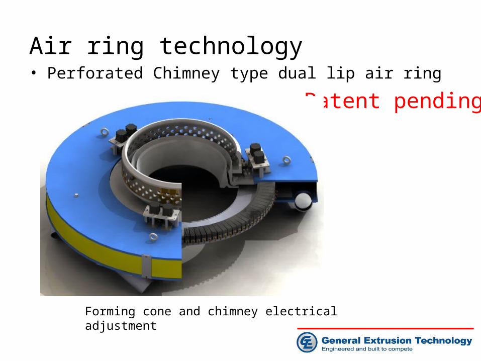
Air ring technology• Perforated Chimney type dual lip air ring
Forming cone and chimney electrical adjustment
Patent pending

Air ring technology• Operation theory of dual lip air ring
Chimney adjustable
Upper lip adjustable
Lower lip
Forming cone

Air ring technology
• Operation theory of dual lip air ring• Lower Lip: provides initial quenching to strengthen the melt
provides venturi between bubble and cone to “set” the bubble
• Forming Cone: guides lower lip air & supports bubble while in the ‘semi-solid’ state
• Upper Lip: provides final “blast” of cooling air “adjustment” provides ability to vary volume & velocity of air -- to process wider variety of materials and BUR’s with same lip geometry
• Chimney device: to further redirect the cooling air and increase the stability of the bubble

• Dual lip air ring
• Adjustable upper lip design for wider BURs
• +/- 0.5% air flow consistency
• Finished aluminum flow surfaces
• Adjustable chimney ring for improved le bubble stability
• Available from 75 to 2200 mm diameter
Air ring technology

Air ring technology• Double stack air ring
• Electrical actuator up/down
adjustment
• Suitable for high speed
extrusion

Air ring technology
• Autoprofile technology• Autoprofile control principle • Autoprofile air ring• Autoprofile die• Autoprofile benefits

Air ring technology• Autoprofile technology
• Autoprofile air ring adjusts according to data from ACS and scanner
• Scanner monitors thickness sends data to ACS
Autoprofile control principle Autoprofile control principle

Air ring technology
• Autoprofile technology• Segmented air ring design
• 104 control zones for a 400 mm die
• 5x104 = 520x(3.5mm x 25mm) air chamber
• A constant air flow blows through heater cartridge
• Air flow touches bubble at very fine area. More precise, more even
• Film thickness control more accurate
3.5mmx25m air chamber

Air ring technology• Autoprofile technology
• Segmented die with heater cartridge in sizing ring
• 64 control zone
Autoprofile dieAutoprofile die
Heater cartridge
Air ring technology
• Autoprofile benefits• Available in fixed or oscillating configuration
• Utilizes PlastControl ACS with any on-line thickness gage
• Varies the cooling effect on specific bubble segments
• Reduces long term repeatable film thickness variations
• Retrofitable to almost any blown film die
• Typical reduction of 30% of TD variation

Air ring technology
• Air ring cooling air supply and die cart
Die cart
Air ring air supply
Die centering and up/down
adjustment
Internal Bubble Cooling (IBC)
•Simulation of typical IBC system•IBC control principle•IBC cooling unit
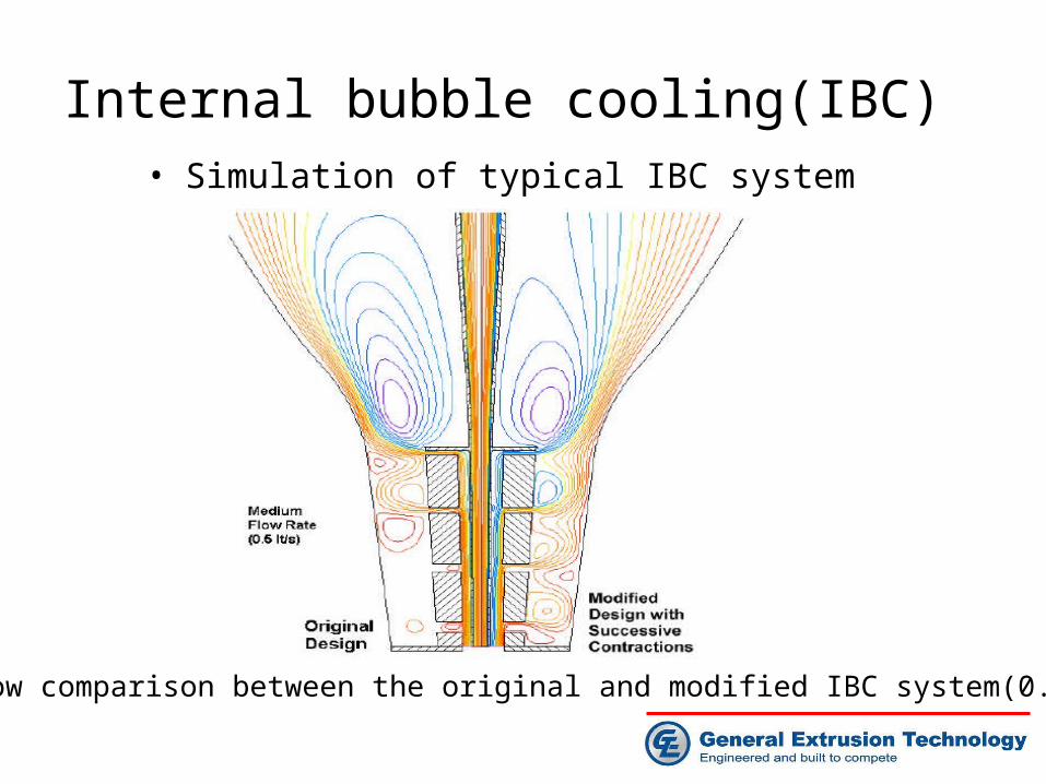
Internal bubble cooling(IBC)• Simulation of typical IBC system
Air flow comparison between the original and modified IBC system(0.5 lt/s)Air flow comparison between the original and modified IBC system(0.5 lt/s)

Internal bubble cooling(IBC)
• IBC control principle
Six sensors system from PlastControlSix sensors system from PlastControl

Internal bubble cooling(IBC) unit• H-Type IBC cooling unit with spiral cooling tube for
high speed extrusion as an option

Internal bubble cooling(IBC)• V-Type IBC cooling unit with spiral cooling tube for
high speed extrusion as an option

Internal bubble cooling(IBC)
• Cooling area: 94cm2
• Heat venting area: 133cm2
• High cooling and venting efficiency. Suitable for high speed extrusion
• IBC Cooling unit design more close to FEA simulation, more cooling capacity
• IBC modular design, easy operation and maintenance • V-Type and H-Type cooling units interchangeable for
different resin and different bubble shape

Bubble cage • Centering bubble perfectly• All extruded alloy aluminum
structure• Whole cage Less than 650 Kg• Easy installation, operation
and maintenance • Aluminum roller cage arm
treated with synergistic coating
• Harder than tool steel upto Rc 65
• Lower COF as low as 0.05• Motorized cage height
adjustment• Electrical actuator bubble
diameter adjustment• PMMA cage cover to protect
bubble from dust and unexpected air turbulence

Bubble cage
• Extruded aluminum roller cage arm • Arm surface treated with
synergistic coating at 30 um thickness
• Hardened surface upto Rc 65
• Lower COF as low as 0.05• Motorized cage height
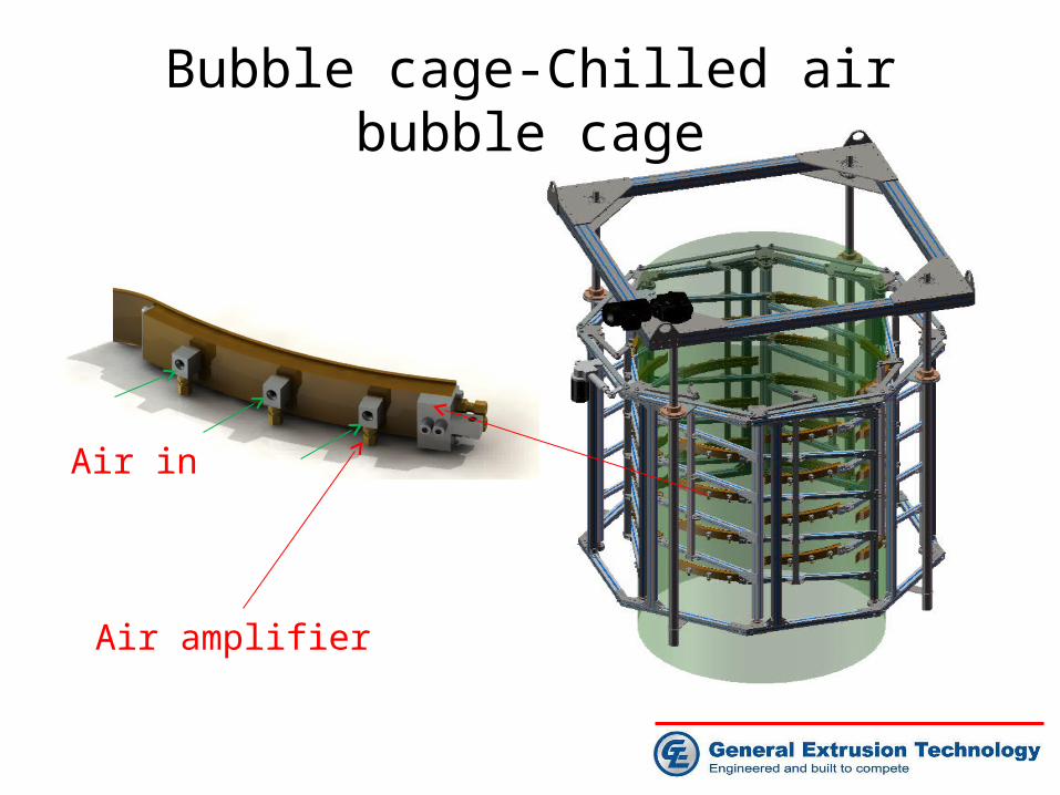
Bubble cage-Chilled air bubble cage
Air amplifier
Air in

Bubble cage-Chilled air bubble cage
• Air blow through copper tube filled with chilly water air on to film bubble
• Eliminate blocking
• Output increase up to 25%
• Scratch free
• Perfect for sticky film and protection film applications
• Better roll quality
Chilled water in/out
Chilled air out
Patent pending
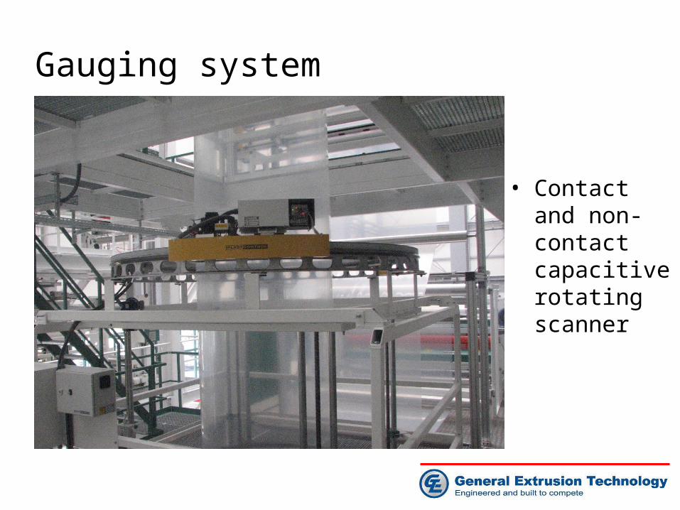
Gauging system
• Contact and non-contact capacitive rotating scanner

Gauging system

Haul-off system
•Stationary primary nip•Horizontal haul-off unit•Collapsing frame•Haul-off system•Second nip station

Haul-off system• Haul-off system

Haul-off system
– Equipped with Mink Web Spreader Brush Roll 10022, Germany– Less scratcher due relative MD or TD film movement– Low wear of nylon brushes– Small contact surface to film and large non contact area– Low heat transfer from film to brush– No roll temperature increase– No film bagging– Less contamination– Light weight, low height, easy installation

Haul-off system
– Mink Web Spreader Brush Roll 10022, Germany

Haul-off system
• Mink Web Spreader Brush Roll 10022, Germany

Haul-off system
• Horizontal haul-off unit Airless turning bar
Spreader roller

Haul-off system
• Horizontal haul-off unitSynergistic surface coating
Surface hardness: upto Rc65
Surface COF as low as 0.05
Heat resistance as high as
4600 C

Haul-off system
• Stationary primary nip
• Gearbox motor direct coupled to steel shaft. No pulley and belt
• High quality HYPAlON rubber roll, long life, low wear
• Easy access and maintenance
• Optional water cooled steel roll

Haul-off system
• Collapsing frame • Assembled with all extruded alloy alum parts, light weight. Easy installation and operation
• Extruded alloy alum slat, Plasma Micro-Arc Oxidation super hard surface treatment
• Lower COF, wear and high temperature resistance
• No film bagging, no film scratch

Web guiding system
• Coast Control all pneumatic web guide system, USA• No motor, no electronics• No hydraulic • Easy installation • Easy operation• 10 years warranty
on all parts

Web guiding system

Web guiding system

Haul-off system
• Secondary nip station
• Avail w/ dancer
or load cell
control
• Variety of roll
finished
available
• Configurable
w/S-wrap
cooling option

Winder Technology
•Surface winder•Central surface winder

Winder technology
• Central/surface/gap winder• Finished roll diameter: 1,500
mm max• Line speed: upto 250 m/min• Tension control: 40-400N,
surface winding,• 15-150N central winding• B&R, Austria, PCC control
system, color touch screen operation. English/Chinese operational language
• Central/surface mode, reversing winding
• Lay-on pressure control• Optional gap winding

Winder technology

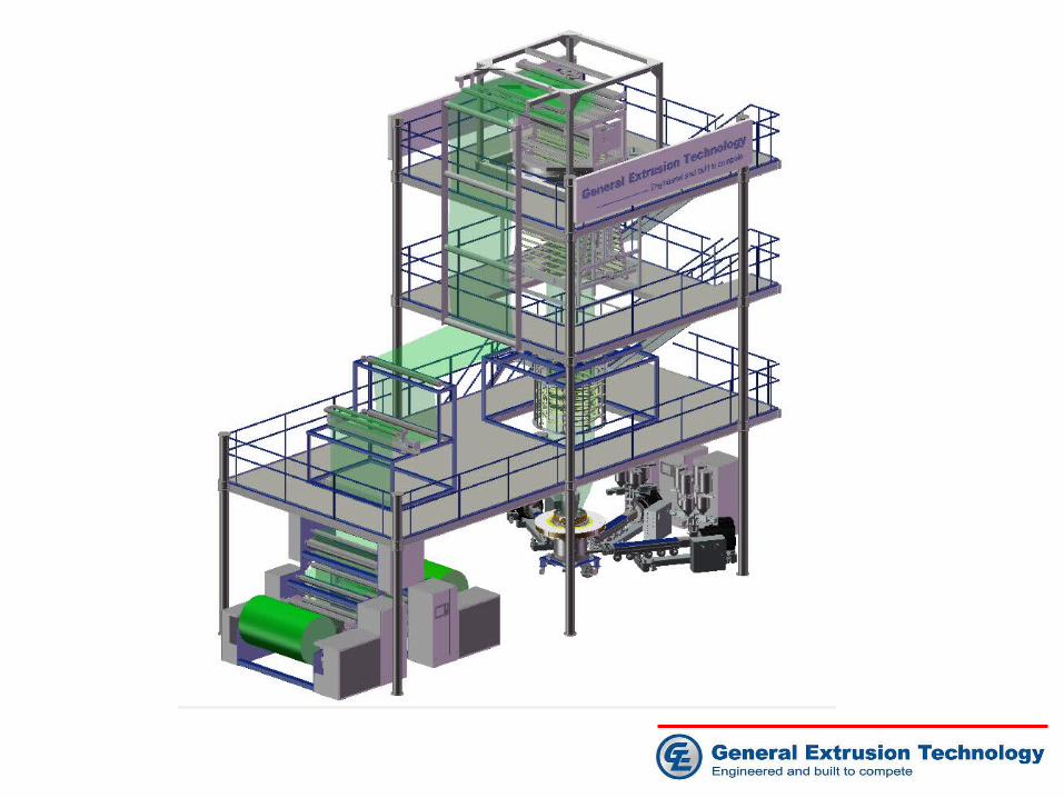
Film tower

Thank you for your attention!

Internal bubble cooling(IBC)
•Simulation of typical IBC system
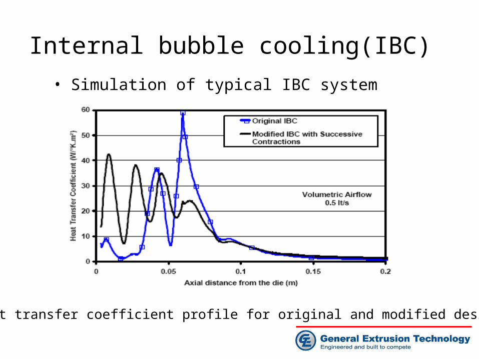
Internal bubble cooling(IBC)
• Simulation of typical IBC system
Heat transfer coefficient profile for original and modified designsHeat transfer coefficient profile for original and modified designs
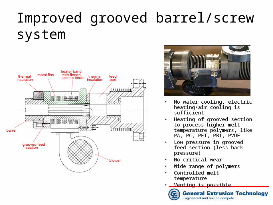
Improved grooved barrel/screw system
• No water cooling, electric heating/air cooling is sufficient
• Heating of grooved section to process higher melt temperature polymers, like PA, PC, PET, PBT, PVDF
• Low pressure in grooved feed section (less back pressure)
• No critical wear• Wide range of polymers• Controlled melt temperature• Venting is possible
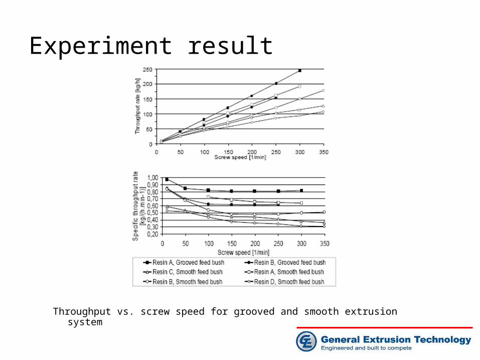
Experiment result
Throughput vs. screw speed for grooved and smooth extrusion system

Experiment result
Throughput and melt temperature vs. screw speed

Experiment result
Back pressure and grooved bore pressure vs. screw speed