blobmaker: free form modelling with variational implicit...
TRANSCRIPT
BlobMaker: Free form Modelling with Variational Implicit Surfaces
Bruno Rodrigues de Araújo IST/ IMMI INESC-ID
Rua Alves Redol, 1000-029 Lisboa [email protected]
Joaquim Armando Pires Jorge Dep. Engª. Informática, IST
Av. Rovisco Pais, 1000 Lisboa [email protected]
Abstract We present BlobMaker, a program for modelling surfaces using variational implicit surfaces. Our approach uses variational implicit surfaces as a geometrical representation for free-form shapes. We have implemented new modelling operations to support stroke (pen-based) input. To this end, we have built a complete modeller application using variational implicit surfaces. Users can create and manipulate shapes using sketches on a perspective or parallel view. The main operations are inflate, which creates 3D forms from a 2D stroke, merge, which creates a 3D shape from two blobs and oversketch, which allows users to redefine shapes using a single stroke to change their boundaries or to modify a surface by an implicit extrusion. We compare these techniques with those of other approaches published. Finally, we describe their implementation in BlobMaker. We have provided additional features such as copying, picking and dragging to offer a natural user interface suitable for free-form modelling.
Keywords Stroke based modelling application, variational implicit surfaces
1. INTRODUCTION Modelling applications have become essential tools in the animation and manufacturing industries and now play a crucial role in the design workflow. However, CAD in-terfaces have not evolved much past the WIMP (Win-dows, Icons, Mouse and Pointing) to match the spectacu-lar increase in modelling power of these systems. There-fore, CAD systems have become very complex, needing high technical knowledge and long learning periods. These problems have made them difficult to use for tradi-tional designers. While WIMP interfaces represent a con-siderable improvement over command line applications, menu-based interactions do not map naturally to pen-and-pencil drawing modes. Analysing the actual com-mand usage in a representative commercial CAD applica-tion, we can verify that 75% of user time is spent in menu navigation, picking and selection instead of model input [Sanchis02]. While this approach was acceptable for in-put via mouse and keyboard the emergence of pen-based systems mandates adopting better input methods. Although pen-based input devices are supported by many modern applications, they are still under-utilised for 3D modelling in contrast to 2D sketching programs. In the later case paper and pencil metaphor can be used to lev-erage both ergonomic and human-learned skills offering advantages in drawing speed, and rich expression af-forded by pen movements and pressure. Applications such as Corel Painter [Corel] constitute a good example of this. However, conventional 3D modelling applica-
tions restrict pen-based input to entering point data. Ex-amples of this are 3D Studio Max [3DMax], Lighwave 3D [Ligthwave3D], Maya [Maya, SoftImage] and CAD systems such as Dassault Systems’ Catia [CATIA]. Even though many of these applications allow some type of free-form modelling, they require detailed knowledge about the geometric representations as NURBS [Farin99] and the intricacies of their mathematical formulations, which makes them difficult to use by traditional design-ers. In the next section, we survey previous work in free form modelling interfaces. Then we present a description of variational implicit surfaces. In sections four and five, we describe in detail our modelling operations based in sketch input. Then we present an implementation of our techniques as embodied in BlobMaker. Finally, we draw conclusions and highlight possible improvements for future work.
2. GESTURE-BASED MODELLING INTERFACES Ivan Sutherland’s SketchPad [Sutherland63] was the first graphical user interface to allow precise drawing using a calligraphic interface, modelling hierarchy and con-straints. In the 1970’s, several research works followed up on these ideas through sketch-based recognition and tablet systems [Negroponte73, Herot76]. In the early 1990’s, the first generation of pen computer fostered the emergence of new interfaces based on sketch input. The SKETCH [Zeleznik96] and SKETCH-N-
MAKE [Bloomenthal98] systems, combined gesture and geometric recognition to allow creating and modifying 3D models. SKETCH defines a specific gesture grammar language to allow the creation of simple 3D primitives in an orthogonal view; for example, three concurrent lines define a cube. This gesture language allows the user to specify CSG operations and to define quasi-free form shapes (such as ducts) through extrusion. Several works have introduced gestures for constructing complex 3D models based on line reconstruction algo-rithms. For example, GIDES [Pereira00] allows users to sketch on an orthogonal view, which combines with a suggestive interface to reduce the command set. The sys-tem provides a language similar to SKETCH to create complex models. It uses specific commands to allow constrained positioning between elements and construc-tion lines to define specific locations, to constrain the output of the recognizer and allow rigorous drawing with imprecise sketches. CHATEAU [Igarashi01] provides another good example of a suggestive interface. Like GIDES and SKETCH COSMO [Mikalik02] it uses a gesture language to specify extrusions. While these sys-tems offer support for reliable extrusions, we need more elaborate functions to support “true” free-form model-ling. REFER[Contero01] and SKETCHUP [Sketchup3D] pro-vide other examples of modelling using line drawings for architectural applications. Both systems feature recogni-tion and reconstruction of models from straight lines. One serious problem with line drawings is the Necker ambiguity [Necker132] characteristic of 3D wire-frame models. The SKETCHUP system, offers new operations for interaction such as face and edge dragging that are much simpler than conventional CSG methods. The different approaches presented here offer good solu-tions for the construction of complex models but are lim-ited to extrusions or their CSG combinations, which offer a poor substitute for free-form shapes. Thus, they are unable to model “soft” forms such as a human head or biological shapes (animals) or surfaces on a car body.
3. SKETCH BASED FREE FORM MODELLING Brian Wyvill [Wyvill98] introduced the BlobTree, which is an implicit surface model based on skeleton primitives to describe soft objects. One prototype system described in this work uses sketches for defining skeleton primi-tives. Skeletons define blobs using a specific language, for example, a line defines a cylinder and a point a sphere. The interesting point of BlobTree, is the combi-nation of implicit surfaces with CSG operations, present-ing a mixture between line-based interaction and a “real” free form approach. However, this method is still too similar in both its virtues and limitations to the gesture-based systems described above. A more familiar approach for free form editing is to sketch in 2D the contours of 3D shapes. This is more natural than using extrusions. The first work using con-tours for free-form modelling was the Teddy system [Iga-
rashi99]. Teddy presents a very simple interface that combines extrusions with contour-based shape creation. The system offers several operations to modify the start-ing shape, which is normally a blob created by inflation of a 2D contour. This system had a great impact in the Computer Graphics community due to its simplicity. It provides simple primitives to extrude, bend, cut or smooth shapes. Geometric representations in Teddy use a triangulated mesh that can be modified through stroke input. Sketches are projected on the mesh according to the current view. However, the system is only able to construct one object and does not support hierarchy. In recent years, several projects have followed the steps of Igarashi. One of the most interesting is Kar-penko’s [Karpenko02], which was the first to adopt a mathematical implicit representation. Like Igarashi, Kar-penko presents a simple interface for free form model-ling. Notably, she models geometrical objects through variational implicit surfaces [Turk99] instead of polygo-nal meshes. We present these in detail in the next section. This application organizes the modelling scene in a tree hierarchy, allowing constrained move operations between tree nodes and creating distinct objects in the same scene. The main operations offered by the interface are merge, which allows combining two blobs and oversketch for redefining the boundary of a blob. Karpenko’s modeller presents simple navigation facilities to allow users to rotate and translate objects. Teddy did not support these features since the whole scene contains a single object. Another interesting aspect is the use of guidance strokes to help the merging process. However, guidance strokes are a symptom that the merging operation could be im-proved and further simplified towards a more natural interaction.
4. VARIATIONAL IMPLICIT SURFACES Variational implicit surfaces (VIS) were introduced by Turk [Turk99, Turk01, Turk02]. VIS are smooth and respect a set of constraint points. VIS are always closed and can have arbitrary topology. They are implicitly defined by a mathematical function f, where the surface is the set of 3D points which verify f(X)=0. Their main difference to other implicit models such as meta-balls [Nishimura85] and BlobTree, lies in that the surface has to obey constraint points specified by the user. VIS are not algebraic surfaces and are based in a problem similar to the thin-plate interpolation. This approach interpolates a cloud of points. To find the implicit function that re-spects all the constraint points with a minimum of curva-ture, f(x) is defined such as to minimize (1):
dXXfXfXfE yyxyxx∫Ω
++= )()(2)( """ (1)
There are several approaches to solve this problem. Turk decomposes f(x) into a linear combination of radial basis functions φ centred on the constraints, using φ(X) =|X|3. The interpolated function, which satisfies the condition presented in (1) and defines the variational implicit sur-face, is presented in (2):
)()()(1
XPcXdXf j
n
jj +−= ∑
=
φ (2)
Where cj are the locations of the constraints on the sur-face, dj are the weight of each constraint, P(X) is a one-degree polynomial which can be omitted if the number of constraints is greater than eight [TURK01]. For the calculation of the weights dj, we know the value hj of the height field for each constraint such as f(cj)= hj. Based on Equation (2), the following linear system is defined in (3): HDM =. (3)
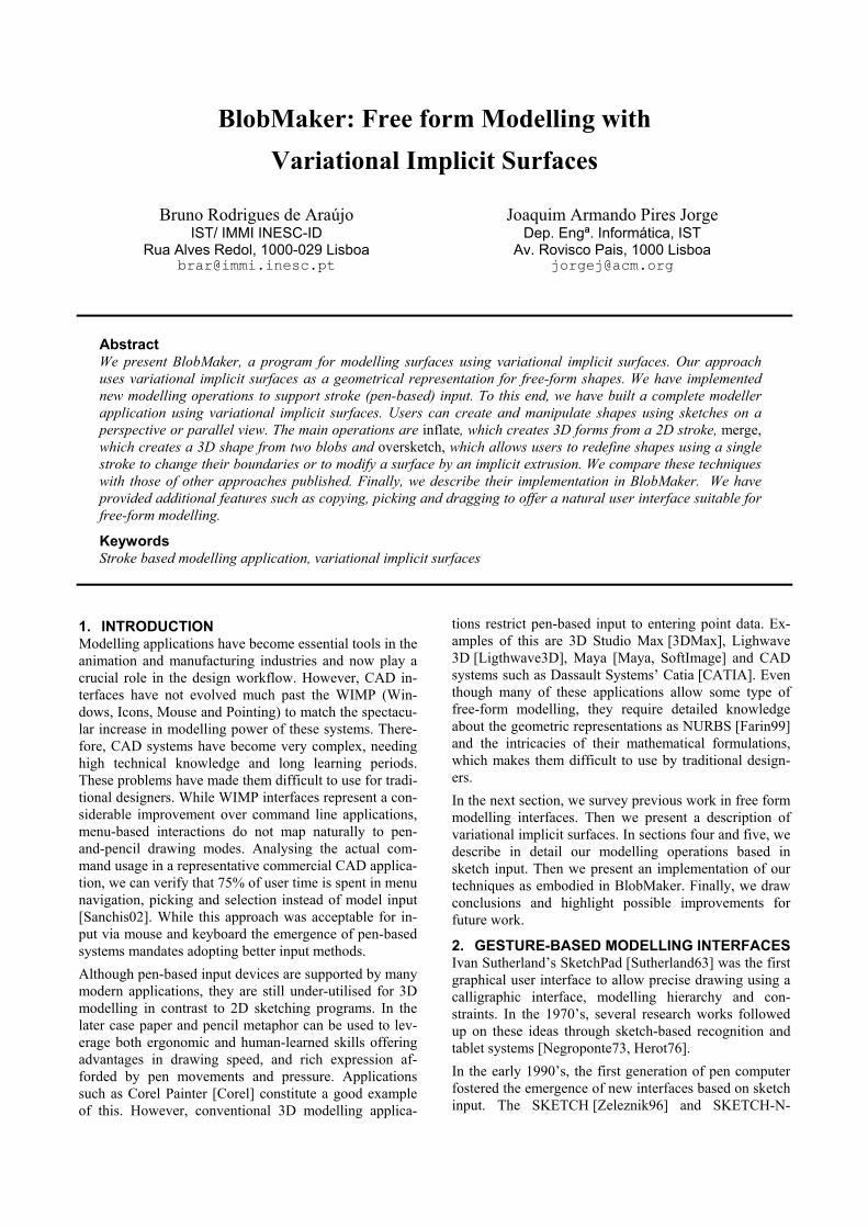
In (3), D= [dj] are the unknowns, H= [hj] are the height field values and M, a matrix defined as a function of φ, P and cj. While the linear system can be solved using LU decomposition in O (k3) steps where k is the number of constraints, iterative methods can solve large-scale sys-tems in O (k2). To simplify creating VIS, Turk proposes a method based on four different types of constraints: • Boundary constraints cj that are placed in the bound-ary of the surface verifying f(cj)=hj with hj=0 • Normal constraints cj that are located outside the surface at a tiny distance of the boundary using the nor-mal of the surface, this constraints verifies f(cj)= hj with hj=1 • Interior constraints cj that are located arbitrary inside the surface verifying f(cj)= hj with hj<0 • Exterior constraints cj that are located arbitrary out-side the surface verifying f(cj)= hj with hj≥1 It is possible to create variational implicit surfaces by specifying only boundary and normal constraints as shown in Figure 1. We can also use this principle for converting polygonal meshes into VIS [Yngve02]. The flexibility of this representation allows modelling complex and smooth models with arbitrary topology. We use it in our modeller, since it provides a compact and mathematically simple means of describing a surface using constraints, weights and a first order polynomial. It affords flexibility for the computation of normal and cur-vature information, while ensuring C2 continuity.
5. FROM 2D TO 3D: INFLATION In this section, we propose our method for the creation of 3D VIS based on user 2D stroke input, using an inflation process similar to [Karpenko02]. We present an overview of the algorithm, followed by the description of the rele-vant steps. The inflation process takes a set of 2D points input by the user (stroke) and creates a 3D object matching the con-tour drawn by the user. The following list presents the different steps of the process: • Filtering the 2D stroke : this step receives the input set of 2D points from the user and simplifies it • Verification of filtered stroke : this step rejects incor-rect parts of the stroke such as self-intersections • Skeletonization of the 2D stroke: this step analyzes the entire stroke and creates a 2D skeleton with all the relevant topological information. The skeleton allows the reconstruction of the input stroke and the information about the thinness of the enclosed region in order to per-form depth inflation • Mapping the 2D stroke into a 3D contour: this step transforms the 2D stroke and skeleton information to a 3D virtual plane according to the actual definition of viewport and view parameters, computing both normal and depth information • Creation of 3D implicit surface and its visualization: this step creates a VIS, representing the blob, which matches the contour’s skeleton. The polygonization proc-ess creates a triangulated mesh together with surface normals at each vertex, which is suitable for rendering
5.1 Main contributions of our work In the previous section, we have presented two different methods from Igarashi and Karpenko to create 3D sur-faces from 2D strokes. Both approaches have advantages and limitations. In Teddy, the inflation process is ori-ented to the triangulated mesh. This approach restricts the possible operations on objects to local mesh modifica-tions. This makes it difficult to merge two meshes. Fur-thermore, triangular meshes make it difficult to model arbitrarily smooth shapes. To overcome this limitation, Igarashi introduced a smoothing operator that applies local subdivision algorithms to the mesh. Even though we use similar methods for skeletonization, Teddy takes a different approach to inflation. While both Igarashi and Karpenko follow the same approach for filtering and mapping the 2D stroke, which is dependent on screen resolution. They reject consecutive 2D points closer than a specified number (15) of pixels. This can result in im-portant details being dropped from the resulting surface. While our approach to inflation is similar to Karpenko’s her method might present incorrect results due to her screen-dependent filtering method and incorrect tech-nique for depth classification. Her approach only defines two constraints on the VIS to define shape thickness. This brings about several limitations. One of them is that the merging operator needs a re-sampling of the triangu-
Figure 1: Example of boundary (o) and normal (+) constraints in variational im-
lated mesh. This increases the number of constraints on the VIS dramatically, thus incurring in additional compu-tational costs for matrix solving. Another consequence is that the merge between a big blob and a very small one will be impossible without loss of detail. In our approach, all modelling operators use only the mathematic repre-sentation and skeleton information. The next sections describe in more detail our inflation process.
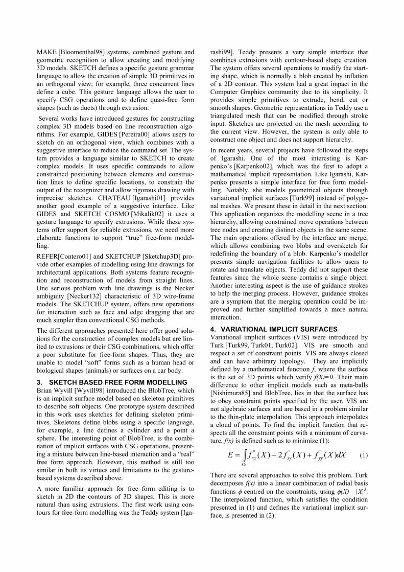
5.2 Filtering the input stroke Since the sampling of stroke points from an electronic digitizer depends of the interrupt processing capability of the operating system, points on an input stroke are not evenly spaced. For example, some points can be repeated or their number can be unnecessarily large depending on the speed at which the stroke was drawn. As discussed before, Igarashi and Karpenko follow an approach for stroke filtering which is dependent on screen resolution. In our approach, we implement a greedy algorithm similar to Douglas-Peucker filter-ing [Douglas73]. Figure 2 presents an input stroke and the result (red points) of the filtering; the input stroke on the left is com-pound by 2081 points and reduces to 92 points after the filtering step. Finally, we analyze the filtered stroke, rejecting self-intersection parts. This step is necessary because the pro-ject boundary of a shape cannot be self-intersecting in a 2D projected plane. In our approach, the first non-intersecting loop found in the filtered stroke remains and the rest of the stroke is rejected. as shows Figure 2.
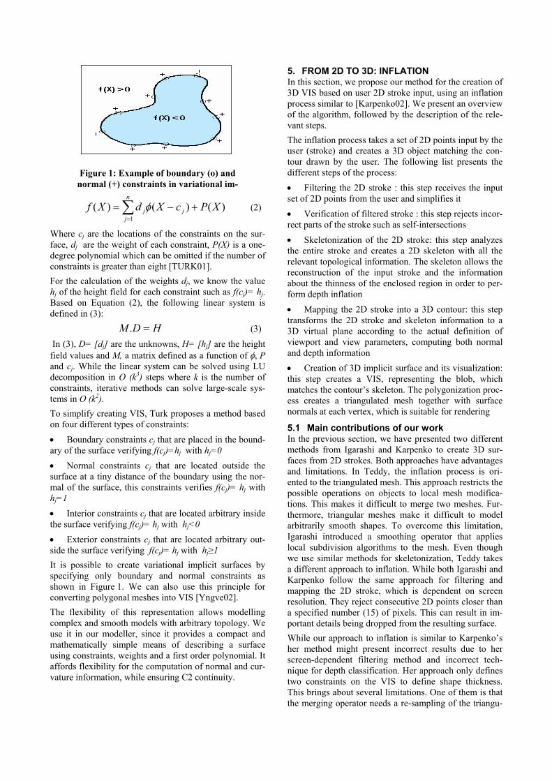
5.3 Skeletonization of 2D Strokes The skeletonization step transforms the filtered stroke too reveal all the information of the stroke. Our approach uses the Chordal Axis Transform presented in [Prasad97], which is normally used for 2D shape recog-nition. The skeletonization receives the input polygon and applies a Constrained Delaunay Triangulation, using as constraints the edges of the filtered stroke. We gener-ate three kinds of connectivity information for the trian-gulated polygon as illustrated in Figure 3, where triangles fall into one of three categories:
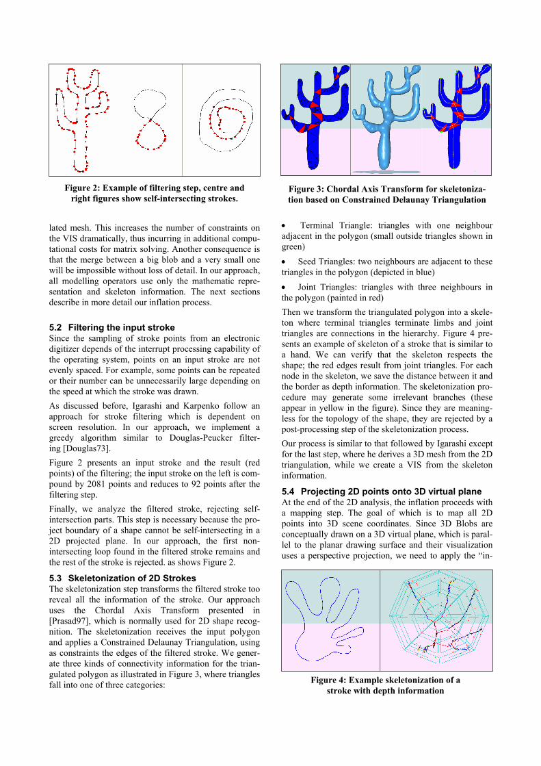
• Terminal Triangle: triangles with one neighbour adjacent in the polygon (small outside triangles shown in green) • Seed Triangles: two neighbours are adjacent to these triangles in the polygon (depicted in blue) • Joint Triangles: triangles with three neighbours in the polygon (painted in red) Then we transform the triangulated polygon into a skele-ton where terminal triangles terminate limbs and joint triangles are connections in the hierarchy. Figure 4 pre-sents an example of skeleton of a stroke that is similar to a hand. We can verify that the skeleton respects the shape; the red edges result from joint triangles. For each node in the skeleton, we save the distance between it and the border as depth information. The skeletonization pro-cedure may generate some irrelevant branches (these appear in yellow in the figure). Since they are meaning-less for the topology of the shape, they are rejected by a post-processing step of the skeletonization process. Our process is similar to that followed by Igarashi except for the last step, where he derives a 3D mesh from the 2D triangulation, while we create a VIS from the skeleton information.
5.4 Projecting 2D points onto 3D virtual plane At the end of the 2D analysis, the inflation proceeds with a mapping step. The goal of which is to map all 2D points into 3D scene coordinates. Since 3D Blobs are conceptually drawn on a 3D virtual plane, which is paral-lel to the planar drawing surface and their visualization uses a perspective projection, we need to apply the “in-
Figure 4: Example skeletonization of a stroke with depth information
Figure 2: Example of filtering step, centre and right figures show self-intersecting strokes.
Figure 3: Chordal Axis Transform for skeletoniza-tion based on Constrained Delaunay Triangulation
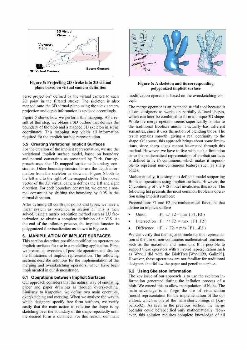
verse projection” defined by the virtual camera to each 2D point in the filtered stroke. The skeleton is also mapped onto the 3D virtual plane using the view camera projection and depth information is updated accordingly. Figure 5 shows how we perform this mapping. As a re-sult of this step, we obtain a 3D outline that defines the boundary of the blob and a mapped 3D skeleton in scene coordinates. This mapping step yields all information required for the implicit surface representation.
5.5 Creating Variational Implicit Surfaces For the creation of the implicit representation, we use the variational implicit surface model, based on boundary and normal constraints as presented by Turk. Our ap-proach uses the 3D mapped stroke as boundary con-straints. Other boundary constraints use the depth infor-mation from the skeleton as shown in Figure 6 both to the left and to the right of the mapped stroke. The lookat vector of the 3D virtual camera defines the left and right direction. For each boundary constraint, we create a nor-mal constraint by shifting the boundary by 0.05 in the normal direction. After defining all constraint points and types, we have a linear system as presented in section 3. This is then solved, using a matrix resolution method such as LU fac-torization, to obtain a complete definition of a VIS. At the end of the inflation process, the implicit function is polygonized for visualization as shown in Figure 6.
6. MANIPULATION OF IMPLICIT SURFACES This section describes possible modification operators on implicit surfaces for use in a modelling application. First, we present an overview of possible operators and discuss the limitations of implicit representation. The following sections describe solutions for the implementation of the merging and oversketching operators, which have been implemented in our demonstrator.
6.1 Operations between Implicit Surfaces Our approach considers that the natural way of emulating paper and paper drawings is through oversketching. Similarly to Karpenko, we define two main operators, oversketching and merging. When we analyze the way in which designers specify free form surfaces, we verify easily that the main action to redefine the shape is by sketching over the boundary of the shape repeatedly until the desired form is obtained. For this reason, our main
modification operator is based on the oversketching con-cept. The merge operator is an extended useful tool because it allows designers to works on partially defined shapes, which can later be combined to form a unique 3D shape. While the merge operator seems superficially similar to the traditional Boolean union, it actually has different semantics, since it uses the notion of blending blobs. The result remains smooth, giving a real continuity to the shape. Of course, this approach brings about some limita-tions, since sharp edges cannot be created through this method. However, we have to live with such a limitation since the mathematical representation of implicit surfaces is defined to be C2 continuous, which makes it impossi-ble to represent non-continuous features such as sharp edges. Mathematically, it is simple to define a model supporting Boolean operations using implicit surfaces. However, the C2 continuity of the VIS model invalidates this issue. The following list presents the most common Booleans opera-tion using implicit surfaces: Precondition: F1 and F2 are mathematical functions that define an implicit surface • Union :F1 ∪ F2 = min ( F1, F2 ) • Intersection :F1 ∩ F2 = max ( F1, F2 ) • Difference :F1 / F2 = max ( F1 , -F2 ) We can verify that the major obstacle for this representa-tion is the use of non-continuous mathematical functions, such as the maximum and minimum. It is possible to support these operators with a hybrid representation such as Wyvill did with the BlobTree [Wyvill99, Galin99]. However, these operations are not familiar for traditional designers that follow the paper and pencil metaphor.
6.2 Using Skeleton Information The key issue of our approach is to use the skeleton in-formation generated during the inflation process of a blob. We extend this to allow manipulation of blobs. The main advantage is to forgo the use of visualization (mesh) representation for the implementation of the op-erators, which is one of the main shortcomings in [Kar-penko02]. As seen in the previous section, the merge operator could be specified only mathematically. How-ever, this solution requires complete knowledge of all
Figure 6: A skeleton and its corresponding polygonized implicit surface
Figure 5: Projecting 2D stroke into 3D virtual plane based on virtual camera definition
mathematical information such as the location of the critical points of the function. This requires us to identify the local, global minimum, maximum or saddle points of the implicit function. [Stander97] presents an approach for this. Using Morse Theory, he is able to extract all the topological information of the shape from the mathematic definition. However, this is both very difficult to imple-ment and costly in computational processing time to guarantee that all the information has been extracted. This approach is not suitable for a real time modelling application. Karpenko presents a suitable solution, which combines the expressiveness of a mathematical formulation of sur-faces with the flexibility of the triangulated mesh for visualization. However, this solution is only suitable for few steps. Repeated application of merge or oversketch-ing operating, adds many unnecessary constraint points due to this resampling. This may easily scale to thou-sands of constraints after a few operations. Generating a VIS anew from these constraints becomes impractical with current hardware. Thus, this approach is not appro-priate for interaction at real time rates. Another limitation is that this resampling automatically erases all features of the shape smaller than the sampling interval. To overcome the limitation identified in her approach, we base our solution on the surface skeleton, its associated depth information and its VIS. Since skeletons can be merged or modified without using the mesh information and the VIS is recreated at each step, this guarantees that small features will be preserved by the modification op-erators without our needing to use the triangulated mesh. While the merge operator blends two skeletons, over-sketching modifies or appends new data to the original skeleton. The interesting feature of this approach is that all strokes input for oversketching define a new skeleton, which we then merge to the original. After merging strokes, we drop all points that lie inside the merged stroke. The following sections present a detailed description of the algorithms for merging and oversketching.
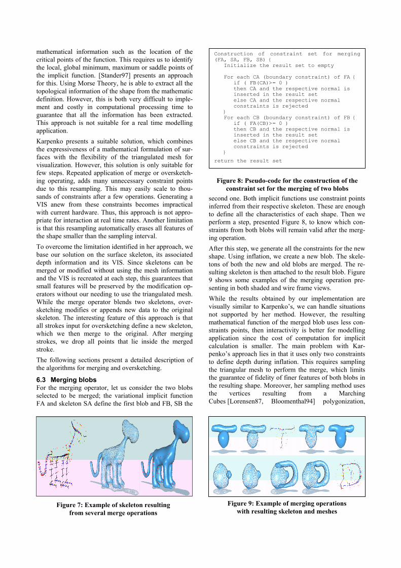
6.3 Merging blobs For the merging operator, let us consider the two blobs selected to be merged; the variational implicit function FA and skeleton SA define the first blob and FB, SB the
second one. Both implicit functions use constraint points inferred from their respective skeleton. These are enough to define all the characteristics of each shape. Then we perform a step, presented Figure 8, to know which con-straints from both blobs will remain valid after the merg-ing operation. After this step, we generate all the constraints for the new shape. Using inflation, we create a new blob. The skele-tons of both the new and old blobs are merged. The re-sulting skeleton is then attached to the result blob. Figure 9 shows some examples of the merging operation pre-senting in both shaded and wire frame views. While the results obtained by our implementation are visually similar to Karpenko’s, we can handle situations not supported by her method. However, the resulting mathematical function of the merged blob uses less con-straints points, then interactivity is better for modelling application since the cost of computation for implicit calculation is smaller. The main problem with Kar-penko’s approach lies in that it uses only two constraints to define depth during inflation. This requires sampling the triangular mesh to perform the merge, which limits the guarantee of fidelity of finer features of both blobs in the resulting shape. Moreover, her sampling method uses the vertices resulting from a Marching Cubes [Lorensen87, Bloomenthal94] polygonization,
Figure 9: Example of merging operations with resulting skeleton and meshes
Figure 7: Example of skeleton resulting from several merge operations
Construction of constraint set for merging (FA, SA, FB, SB) Initialize the result set to empty For each CA (boundary constraint) of FA if ( FB(CA)>= 0 ) then CA and the respective normal is inserted in the result set else CA and the respective normal constraints is rejected For each CB (boundary constraint) of FB if ( FA(CB)>= 0 ) then CB and the respective normal is inserted in the result set else CB and the respective normal constraints is rejected return the result set
Figure 8: Pseudo-code for the construction of the constraint set for the merging of two blobs
which depends on the size of the subdivision and yields too many constraints on the merged shape. While our approach uses more constraints to define the object in the inflation process, the merged blob has fewer constraints.
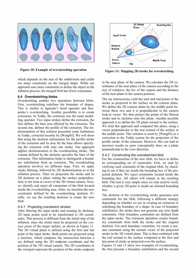
6.4 Oversketching blobs Oversketching enables two operations between blobs. First, oversketching redefines the boundary of shapes. This is similar to Igarashi’s bend operator and Kar-penko’s oversketching. Another possibility is to create extrusions. In Teddy, the extrusion was the main model-ling operator. Two input strokes define the extrusion, the first defines the base area affected by the extrusion. The second one, defines the profile of the extrusion. The im-plementation of this solution presented some limitations in Teddy, corrected recently by [Wang03]. We will show that using the skeleton information for the profile stroke of the extrusion and its area for the base allows specify-ing the extrusion with only one stroke. Our approach applies skeletonization to the oversketching stroke. The volume defined by the skeleton specifies the base of the extrusion. This information helps to distinguish a bound-ary redefinition from an extrusion. The oversketching operation involves six different steps. First, we apply stroke filtering, followed by 2D skeletonization as in the inflation process. Then we projection the stroke and its 2D skeleton on a plane cutting the surface perpendicu-larly to the look-at vector of the 3D virtual camera. Next, we identify and reject all constraints of the blob located inside the oversketching area. After, we insertion the new constraints defined by the oversketching skeleton. Fi-nally, we use the resulting skeleton to create the new blob.
6.4.1 Projecting oversketch strokes After filtering the input stroke and creating its skeleton, 2D input points need to be transformed to 3D coordi-nates. This process is different from the initial step of the inflation, since the stroke must be projected on the con-tour plane of the target surface, as shown in Figure 11. The 3D virtual plane is defined using the first and last point of the input stroke. Both points are projected using a function, which computes the intersection between a ray defined using the 2D endpoint coordinate and the position of the 3D virtual camera. The 2D coordinates in the viewport represent the position of the stroke endpoint
in the near plane of the camera. We calculate the 3D co-ordinates of the near plane of the camera according to the size of windows, the fov of the camera and the distance of the near plane to the camera position. The ray intersections yield the start and end points of the stroke as projected in the surface on the contour plane. We define the 3D contour plane by the middle point be-tween these two and it is perpendicular to the camera look-at vector. We then project the points of the filtered stroke and its skeleton onto this plane. Another possible approach is to define the 3D plane normal to the surface. We tried this approach and computed this plane, using a vector perpendicular to the true normal of the surface at the middle point. This solution is used by [Wang03] as a correction to the Teddy system for the projection of the profile stroke of the extrusion. However, this can lead to incorrect results as users conceptually draw on a plane perpendicular to the view direction.
6.4.2 Constructing the oversketched blob For the construction of the new blob, we have to define its corresponding set of constraints. First, we start by verifying each constraint of the original blob, by check-ing to see if they are inside the bounding box of the pro-jected skeleton. We reject constraints located inside the bounding box. All others will remain in the resulting blob. This test is very simple since we only need to verify whether a given 3D point is inside an oriented bounding box. The skeleton of the oversketching stroke generates new constraints for the blob, following a different strategy depending on whether we are in creating an extrusion or redefining the boundary of a shape. In case of boundary redefinition, the stroke does not generate any new depth constraints. Only boundary constraints are defined from the input stroke. The extrusion operation creates bound-ary constraints from both the stroke and the original skeleton. For each boundary constraint, we create a nor-mal constraint using the normal vector of the projected stroke in the 3D virtual plane. This is then combined with the real normal to the surface computed at the first and last point of stroke as projected over the surface. Figures 12 and 13 show two examples of oversketching; the first presents a boundary redefinition and the second
Figure 10: Example of oversketching operation Figure 11: Mapping 2D stroke for oversketching
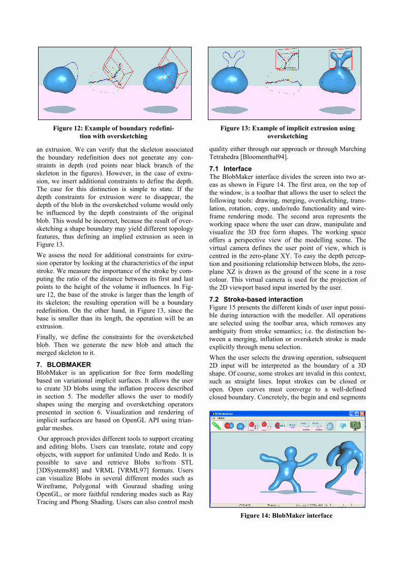
an extrusion. We can verify that the skeleton associated the boundary redefinition does not generate any con-straints in depth (red points near black branch of the skeleton in the figures). However, in the case of extru-sion, we insert additional constraints to define the depth. The case for this distinction is simple to state. If the depth constraints for extrusion were to disappear, the depth of the blob in the oversketched volume would only be influenced by the depth constraints of the original blob. This would be incorrect, because the result of over-sketching a shape boundary may yield different topology features, thus defining an implied extrusion as seen in Figure 13. We assess the need for additional constraints for extru-sion operator by looking at the characteristics of the input stroke. We measure the importance of the stroke by com-puting the ratio of the distance between its first and last points to the height of the volume it influences. In Fig-ure 12, the base of the stroke is larger than the length of its skeleton; the resulting operation will be a boundary redefinition. On the other hand, in Figure 13, since the base is smaller than its length, the operation will be an extrusion. Finally, we define the constraints for the oversketched blob. Then we generate the new blob and attach the merged skeleton to it.
7. BLOBMAKER BlobMaker is an application for free form modelling based on variational implicit surfaces. It allows the user to create 3D blobs using the inflation process described in section 5. The modeller allows the user to modify shapes using the merging and oversketching operators presented in section 6. Visualization and rendering of implicit surfaces are based on OpenGL API using trian-gular meshes. Our approach provides different tools to support creating and editing blobs. Users can translate, rotate and copy objects, with support for unlimited Undo and Redo. It is possible to save and retrieve Blobs to/from STL [3DSystems88] and VRML [VRML97] formats. Users can visualize Blobs in several different modes such as Wireframe, Polygonal with Gouraud shading using OpenGL, or more faithful rendering modes such as Ray Tracing and Phong Shading. Users can also control mesh
quality either through our approach or through Marching Tetrahedra [Bloomenthal94].
7.1 Interface The BlobMaker interface divides the screen into two ar-eas as shown in Figure 14. The first area, on the top of the window, is a toolbar that allows the user to select the following tools: drawing, merging, oversketching, trans-lation, rotation, copy, undo/redo functionality and wire-frame rendering mode. The second area represents the working space where the user can draw, manipulate and visualize the 3D free form shapes. The working space offers a perspective view of the modelling scene. The virtual camera defines the user point of view, which is centred in the zero-plane XY. To easy the depth percep-tion and positioning relationship between blobs, the zero-plane XZ is drawn as the ground of the scene in a rose colour. This virtual camera is used for the projection of the 2D viewport based input inserted by the user.
7.2 Stroke-based interaction Figure 15 presents the different kinds of user input possi-ble during interaction with the modeller. All operations are selected using the toolbar area, which removes any ambiguity from stroke semantics; i.e. the distinction be-tween a merging, inflation or oversketch stroke is made explicitly through menu selection. When the user selects the drawing operation, subsequent 2D input will be interpreted as the boundary of a 3D shape. Of course, some strokes are invalid in this context, such as straight lines. Input strokes can be closed or open. Open curves must converge to a well-defined closed boundary. Concretely, the begin and end segments
Figure 12: Example of boundary redefini-tion with oversketching
Figure 14: BlobMaker interface
Figure 13: Example of implicit extrusion using oversketching
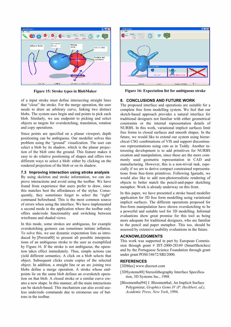
of a input stroke must define intersecting straight lines that “close” the stroke. For the merge operation, the user needs to draw an arbitrary curve, linking two distinct blobs. The system uses begin and end points to pick each blob. Similarly, we use endpoint to picking and select objects as targets for oversketching, translation, rotation and copy operations. Since points are specified on a planar viewport, depth positioning can be ambiguous. Our modeller solves this problem using the “ground” visualization. The user can select a blob by its shadow, which is the planar projec-tion of the blob onto the ground. This feature makes it easy to do relative positioning of shapes and offers two different ways to select a blob: either by clicking on the rendered projection of the blob or on its shadow.
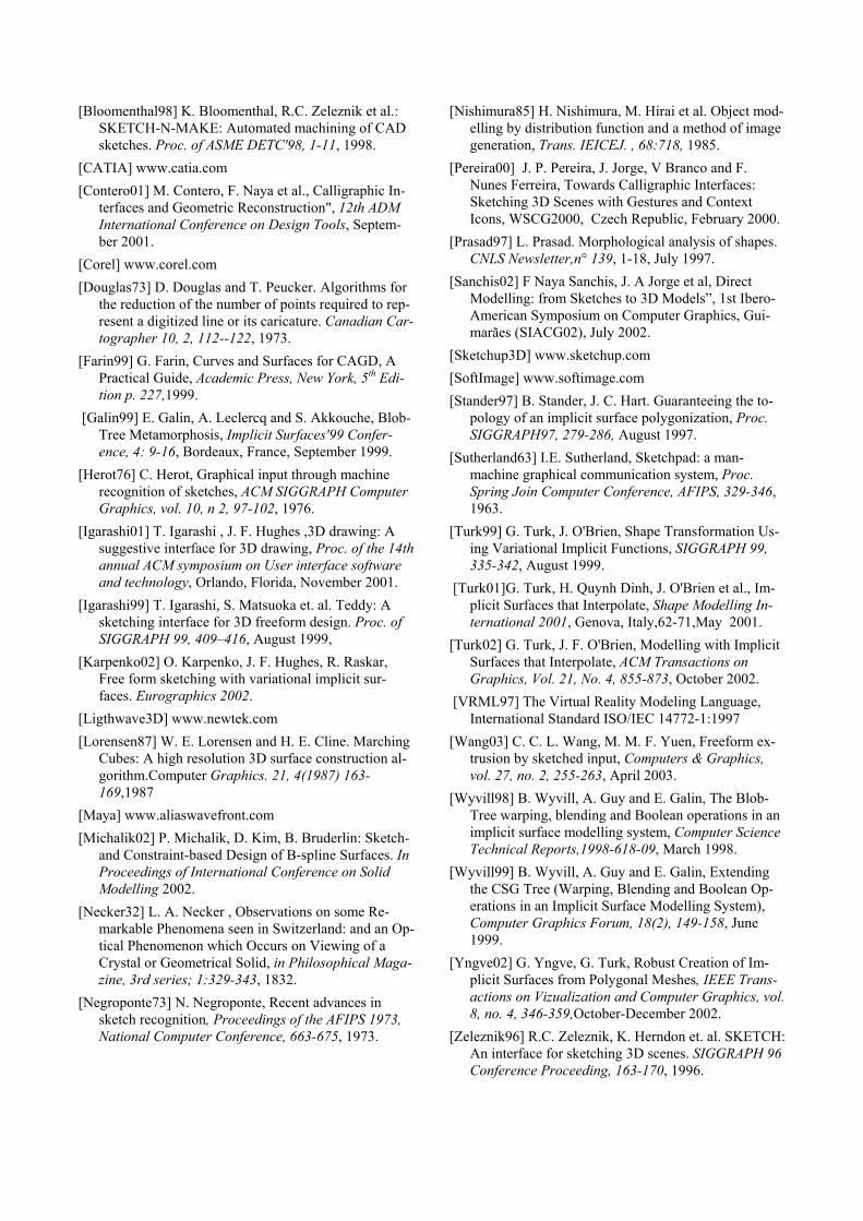
7.3 Improving interaction using stroke analysis By using skeleton and stroke information, we can im-prove interactions and avoid using the toolbar. We have found from experience that users prefer to draw, since this matches best the affordances of the stylus. Conse-quently, they sometimes forget to select the “right” command beforehand. This is the most common source of errors when using the interface. We have implemented a second mode in the application where the toolbar only offers undo/redo functionality and switching between wireframe and shaded views. In this mode, some strokes are ambiguous, for example oversketching gestures can sometimes initiate inflation. To solve this, we use dynamic expectation lists as intro-duced by [Pereira00] to present all possible interpreta-tions of an ambiguous stroke to the user as exemplified by Figure 16. If the stroke is not ambiguous, the opera-tion takes effect immediately. Thus, simple actions can yield different semantics. A click on a blob selects that object. Subsequent clicks create copies of the selected object. In addition, a straight line or an arc joining two blobs define a merge operation. A stroke whose end-points lie on the same blob defines an oversketch opera-tion on that blob. A closed stroke or a similar curve cre-ates a new shape. In this manner, all the main interactions can be sketch-based. This mechanism can also avoid use-less undo/redo commands due to erroneous use of but-tons in the toolbar.
8. CONCLUSIONS AND FUTURE WORK The proposed interface and operations are suitable for a complete free form modelling system. We feel that our sketch-based approach provides a natural interface for traditional designers not familiar with either geometrical constraints or the internal representation details of NURBS. In this work, variational implicit surfaces limit free forms to closed surfaces and smooth shapes. In the future, we would like to extend our system using hierar-chical CSG combinations of VIS and support discontinu-ous representations using cuts as in Teddy. Another in-teresting development is to add primitives for NURBS creation and manipulation, since these are the more com-monly used geometric representation in CAD and manufacturing. However, this is a non-trivial task, espe-cially if we are to derive compact constrained representa-tions from free-form primitives. Following Igarashi, we would also like to add non-photorrealistic rendering of objects to better match the pencil-and-paper sketching metaphor. Work is already underway on this front. In this paper, we have presented a stroke based modeller application for 3D free form modelling using variational implicit surfaces. The different operations proposed for free-form manipulation have shown oversketching to be a powerful and suitable tool for 3D modelling. Informal evaluations show great promise for this tool as being more adequate for traditional designers, who are familiar to the pencil and paper metaphor. This too, should be assessed by extensive usability evaluations in the future.
ACKNOWLEDGMENTS This work was supported in part by European Commis-sion through grant # IST-2000-28169 (SmartSketches) and by the Portuguese Science Foundation through grant under grant POSI/34672/SRI/2000.
REFERENCES [3DMax] www.discreet.com [3DSystems88] Stereolithography Interface Specifica-
tion, 3D Systems Inc., 1988. [Bloomenthal94] J. Bloomenthal, An Implicit Surface
Polygonizer, Graphics Gems IV (P. Heckbert, ed.), Academic Press, New York, 1994.
Figure 15: Stroke types in BlobMaker Figure 16: Expectation list for ambiguous stroke
[Bloomenthal98] K. Bloomenthal, R.C. Zeleznik et al.: SKETCH-N-MAKE: Automated machining of CAD sketches. Proc. of ASME DETC'98, 1-11, 1998.
[CATIA] www.catia.com [Contero01] M. Contero, F. Naya et al., Calligraphic In-
terfaces and Geometric Reconstruction", 12th ADM International Conference on Design Tools, Septem-ber 2001.
[Corel] www.corel.com [Douglas73] D. Douglas and T. Peucker. Algorithms for
the reduction of the number of points required to rep-resent a digitized line or its caricature. Canadian Car-tographer 10, 2, 112--122, 1973.
[Farin99] G. Farin, Curves and Surfaces for CAGD, A Practical Guide, Academic Press, New York, 5th Edi-tion p. 227,1999.
[Galin99] E. Galin, A. Leclercq and S. Akkouche, Blob-Tree Metamorphosis, Implicit Surfaces'99 Confer-ence, 4: 9-16, Bordeaux, France, September 1999.
[Herot76] C. Herot, Graphical input through machine recognition of sketches, ACM SIGGRAPH Computer Graphics, vol. 10, n 2, 97-102, 1976.
[Igarashi01] T. Igarashi , J. F. Hughes ,3D drawing: A suggestive interface for 3D drawing, Proc. of the 14th annual ACM symposium on User interface software and technology, Orlando, Florida, November 2001.
[Igarashi99] T. Igarashi, S. Matsuoka et. al. Teddy: A sketching interface for 3D freeform design. Proc. of SIGGRAPH 99, 409–416, August 1999,
[Karpenko02] O. Karpenko, J. F. Hughes, R. Raskar, Free form sketching with variational implicit sur-faces. Eurographics 2002.
[Ligthwave3D] www.newtek.com [Lorensen87] W. E. Lorensen and H. E. Cline. Marching
Cubes: A high resolution 3D surface construction al-gorithm.Computer Graphics. 21, 4(1987) 163-169,1987
[Maya] www.aliaswavefront.com [Michalik02] P. Michalik, D. Kim, B. Bruderlin: Sketch-
and Constraint-based Design of B-spline Surfaces. In Proceedings of International Conference on Solid Modelling 2002.
[Necker32] L. A. Necker , Observations on some Re-markable Phenomena seen in Switzerland: and an Op-tical Phenomenon which Occurs on Viewing of a Crystal or Geometrical Solid, in Philosophical Maga-zine, 3rd series; 1:329-343, 1832.
[Negroponte73] N. Negroponte, Recent advances in sketch recognition, Proceedings of the AFIPS 1973, National Computer Conference, 663-675, 1973.
[Nishimura85] H. Nishimura, M. Hirai et al. Object mod-elling by distribution function and a method of image generation, Trans. IEICEJ. , 68:718, 1985.
[Pereira00] J. P. Pereira, J. Jorge, V Branco and F. Nunes Ferreira, Towards Calligraphic Interfaces: Sketching 3D Scenes with Gestures and Context Icons, WSCG2000, Czech Republic, February 2000.
[Prasad97] L. Prasad. Morphological analysis of shapes. CNLS Newsletter,n° 139, 1-18, July 1997.
[Sanchis02] F Naya Sanchis, J. A Jorge et al, Direct Modelling: from Sketches to 3D Models”, 1st Ibero-American Symposium on Computer Graphics, Gui-marães (SIACG02), July 2002.
[Sketchup3D] www.sketchup.com [SoftImage] www.softimage.com [Stander97] B. Stander, J. C. Hart. Guaranteeing the to-
pology of an implicit surface polygonization, Proc. SIGGRAPH97, 279-286, August 1997.
[Sutherland63] I.E. Sutherland, Sketchpad: a man-machine graphical communication system, Proc. Spring Join Computer Conference, AFIPS, 329-346, 1963.
[Turk99] G. Turk, J. O'Brien, Shape Transformation Us-ing Variational Implicit Functions, SIGGRAPH 99, 335-342, August 1999.
[Turk01]G. Turk, H. Quynh Dinh, J. O'Brien et al., Im-plicit Surfaces that Interpolate, Shape Modelling In-ternational 2001, Genova, Italy,62-71,May 2001.
[Turk02] G. Turk, J. F. O'Brien, Modelling with Implicit Surfaces that Interpolate, ACM Transactions on Graphics, Vol. 21, No. 4, 855-873, October 2002.
[VRML97] The Virtual Reality Modeling Language, International Standard ISO/IEC 14772-1:1997
[Wang03] C. C. L. Wang, M. M. F. Yuen, Freeform ex-trusion by sketched input, Computers & Graphics, vol. 27, no. 2, 255-263, April 2003.
[Wyvill98] B. Wyvill, A. Guy and E. Galin, The Blob-Tree warping, blending and Boolean operations in an implicit surface modelling system, Computer Science Technical Reports,1998-618-09, March 1998.
[Wyvill99] B. Wyvill, A. Guy and E. Galin, Extending the CSG Tree (Warping, Blending and Boolean Op-erations in an Implicit Surface Modelling System), Computer Graphics Forum, 18(2), 149-158, June 1999.
[Yngve02] G. Yngve, G. Turk, Robust Creation of Im-plicit Surfaces from Polygonal Meshes, IEEE Trans-actions on Vizualization and Computer Graphics, vol. 8, no. 4, 346-359,October-December 2002.
[Zeleznik96] R.C. Zeleznik, K. Herndon et. al. SKETCH: An interface for sketching 3D scenes. SIGGRAPH 96 Conference Proceeding, 163-170, 1996.