black gas - jm eagle to counteract ... it is . hdpe black gas technical & installation guide....
TRANSCRIPT
Building essentials for a better tomorrow TECHNICAL & INSTALLATION GUIDE
HIGH-DENSITy
POLyETHyLENEBLACK GAS
ASTM D2513; OIL & GAS GATHERING PIPE API 15 LE


INTRODUCTION . . . . . . . . . . . . . . . . . . . . . . . . . . . . . . . . . . . . . . . . . . . . 6
PRODUCT & TECHNICAL INFORMATION . . . . . . . . . . . . . . . . . . . . . . . . 6
CODE COMPLIANCE . . . . . . . . . . . . . . . . . . . . . . . . . . . . . . . . . . . . . . 6
PHySICAL PROPERTIES . . . . . . . . . . . . . . . . . . . . . . . . . . . . . . . . . . . 7
LONG-TERM STRENGTH . . . . . . . . . . . . . . . . . . . . . . . . . . . . . . . . . . 7
PIPE PRESSURE RATING . . . . . . . . . . . . . . . . . . . . . . . . . . . . . . . . . . 7
EFFECT OF ENvIRONMENTAL ExPOSURE ON PHySICAL PROPERTIES . . . 8
CHEMICAL RESISTANCE . . . . . . . . . . . . . . . . . . . . . . . . . . . . . 8
WEATHER RESISTANCE . . . . . . . . . . . . . . . . . . . . . . . . . . . . . . 8
INSTALLATION TEMPERATURES . . . . . . . . . . . . . . . . . . . . . . . 8
THERMAL ExPANSION AND CONTRACTION . . . . . . . . . . . . . 9
PERMEATION . . . . . . . . . . . . . . . . . . . . . . . . . . . . . . . . . . . . . . 9
EFFECT OF ExTERNAL LOADING STRESSES . . . . . . . . . . . . 10
PLASTIC PIPE DAMAGE & REPAIR . . . . . . . . . . . . . . . . . . . . 10
PRODUCT DISPOSAL . . . . . . . . . . . . . . . . . . . . . . . . . . . . . . 11
INSTALLATION GUIDELINES . . . . . . . . . . . . . . . . . . . . . . . . . . . . . . . . . . 11
HANDLING . . . . . . . . . . . . . . . . . . . . . . . . . . . . . . . . . . . . . . . . . . . . . 11
UNLOADING AND LOADING . . . . . . . . . . . . . . . . . . . . . . . . . . . . . . . 12
STRINGING . . . . . . . . . . . . . . . . . . . . . . . . . . . . . . . . . . . . . . . . . . . . 12
DRAGGING . . . . . . . . . . . . . . . . . . . . . . . . . . . . . . . . . . . . . . . . . . . . 13
CUTTING . . . . . . . . . . . . . . . . . . . . . . . . . . . . . . . . . . . . . . . . . . . . . . 13
COLD-WEATHER HANDLING . . . . . . . . . . . . . . . . . . . . . . . . . . . . . . 13
1.0
2.0
2.1
2.2
2.3
2.4
2.5
2.5.1
2.5.2
2.5.3
2.5.4
2.5.5
2.5.6
2.5.7
2.5.8
3.0
3.1
3.2
3.3
3.4
3.5
3.6
CONTENTS
HIGH-DENSITy
POLyETHyLENEBLACK GAS
OTHER HANDLING PRECAUTIONS . . . . . . . . . . . . . . . . . . . . . . . 14
TRENCHING . . . . . . . . . . . . . . . . . . . . . . . . . . . . . . . . . . . . . . . . . 14
PIPE PLACEMENT IN TRENCHES . . . . . . . . . . . . . . . . . . . . . . . . . 15
vALvE INSTALLATION . . . . . . . . . . . . . . . . . . . . . . . . . . . . . . . . . . 15
PIPE LOCATING . . . . . . . . . . . . . . . . . . . . . . . . . . . . . . . . . . . . . . . 15
BACKFILLING & COMPACTION . . . . . . . . . . . . . . . . . . . . . . . . . . . 16
PERMANENT MINIMUM BENDING RADIUS LIMITS . . . . . . . . . . . 17
INSERTION RENEWAL . . . . . . . . . . . . . . . . . . . . . . . . . . . . . . . . . 17
PRESSURE TESTING AND LEAK DETECTION . . . . . . . . . . . . . . . . 18
SAFETy AND FIELD PRECAUTIONS . . . . . . . . . . . . . . . . . . . . . . . 20
HEATING TOOL MAINTENANCE . . . . . . . . . . . . . . . . . . . . . . . . . . 21
FUSION PROCEDURES . . . . . . . . . . . . . . . . . . . . . . . . . . . . . . . . . . . . . 21
SOCKET FUSION . . . . . . . . . . . . . . . . . . . . . . . . . . . . . . . . . . . . . . 21
EqUIPMENT . . . . . . . . . . . . . . . . . . . . . . . . . . . . . . . . . . . . 21
PROCEDURES . . . . . . . . . . . . . . . . . . . . . . . . . . . . . . . . . . 22
TABLE 1 . . . . . . . . . . . . . . . . . . . . . . . . . . . . . . . . . . . . 23
COLD-WEATHER CONSIDERATIONS (BELOW 55ºF) . . . . . 24
BUTT FUSION . . . . . . . . . . . . . . . . . . . . . . . . . . . . . . . . . . . . . . . . 25
HEATING TIME . . . . . . . . . . . . . . . . . . . . . . . . . . . . . . . . . . 25
INTERFACIAL PRESSURE . . . . . . . . . . . . . . . . . . . . . . . . . . 25
HOLDING & COOLING TIME . . . . . . . . . . . . . . . . . . . . . . . . 25
EqUIPMENT . . . . . . . . . . . . . . . . . . . . . . . . . . . . . . . . . . . . 26
PROCEDURES . . . . . . . . . . . . . . . . . . . . . . . . . . . . . . . . . . 26
COLD WEATHER CONSIDERATIONS (BELOW 55ºF) . . . . . 28
TABLE 2 . . . . . . . . . . . . . . . . . . . . . . . . . . . . . . . . . . . . 29
TABLE 3 . . . . . . . . . . . . . . . . . . . . . . . . . . . . . . . . . . . . 29
3.7
3.8
3.9
3.10
3.11
3.12
3.13
3.14
3.15
3.16
3.17
4.0
4.1
4.1.1
4.1.2
4.1.3
4.2
4.2.1
4.2.2
4.2.3
4.2.4
4.2.5
4.2.6
SADDLE OR SIDEWALL FUSION PROCEDURE . . . . . . . . . . . . . . . . . . 30
EqUIPMENT . . . . . . . . . . . . . . . . . . . . . . . . . . . . . . . . . . . . . . 30
PROCEDURES . . . . . . . . . . . . . . . . . . . . . . . . . . . . . . . . . . . . 30
TABLE 4 . . . . . . . . . . . . . . . . . . . . . . . . . . . . . . . . . . . . . . 31
TABLE 5 . . . . . . . . . . . . . . . . . . . . . . . . . . . . . . . . . . . . . . 31
TABLE 6 . . . . . . . . . . . . . . . . . . . . . . . . . . . . . . . . . . . . . . 32
HEAT FUSION qUALIFICATION . . . . . . . . . . . . . . . . . . . . . . . . . . . . . 33
TABLE 7 . . . . . . . . . . . . . . . . . . . . . . . . . . . . . . . . . . . . . . 33
DOT REGULATIONS FOR PROCEDURES AND
PERSONNEL qUALIFICATION . . . . . . . . . . . . . . . . . . . . . . . . 34
PROCEDURES FOR HEAT FUSION qUALIFICATION . . . . . . . 35
SqUEEZE-OFF . . . . . . . . . . . . . . . . . . . . . . . . . . . . . . . . . . . . . . . . . . . . 37
TOOLS . . . . . . . . . . . . . . . . . . . . . . . . . . . . . . . . . . . . . . . . . . . . . . . 37
PRECAUTIONS FOR SqUEEZE-OFF . . . . . . . . . . . . . . . . . . . . . . . . 38
STATIC ELECTRICITy . . . . . . . . . . . . . . . . . . . . . . . . . . . . . . . . . . . . 39
4.3
4.3.1
4.3.2
4.4
4.4.1
4.4.2
5.0
5.1
5.2
5.3
4 HDPE BLACK GAS TECHNICAL & INSTALLATION GUIDE
Warranty
J-M Manufacturing Company Inc. (JM Eagle™) warrants that its standard polyvinyl chloride (PvC), polyethylene (PE), conduit/plumbing/solvent weld and Acrylonitrile-Butadiene-Styrene (ABS) pipe products (“Products”) are manufactured in accordance with applicable industry specifications referenced on the Product and are free from defects in workmanship and materials. Every claim under this warranty shall be void unless in writing and received by JM Eagle™ within 30 days of the date the defect was discovered, and within one year of the date of shipment from the JM Eagle™ plant. Claims for Product appearance defects, such as sun-bleached pipe etc., however, must be made within 30 days of the date of the shipment from the JM Eagle™ plant. This warranty specifically excludes any Products allowed to become sun-bleached after shipment from the JM Eagle™ plant. Proof of purchase with the date thereof must be presented to the satisfaction of JM Eagle™, with any claim made pursuant to this warranty. JM Eagle™ must first be given an opportunity to inspect the alleged defective Products in order to determine if it meets applicable industry standards, if the handling and installation have been satisfactorily performed in accordance with JM Eagle™ recommended practices and if operating conditions are within standards. Written permission and/or a Return Goods Authorization (RGA) must be obtained along with instructions for return shipment to JM Eagle™ of any Products claimed to be defective.
The limited and exclusive remedy for breach of this Limited Warranty shall be, at JM Eagle’s sole discretion, the replacement of the same type, size and like quantity of non-defective Product, or credits, offsets or combination of thereof, for the wholesale purchase price of the defective unit.
This Limited Warranty does not apply for any Product failures caused by user’s flawed designs or specifications, unsatisfactory applications, improper installations, use in conjunction with incompatible materials, contact with aggressive chemical agents, freezing or overheating of liquids in the Product and any other misuse causes not listed here. This Limited Warranty also excludes failure or damage caused by fire stopping materials, tread sealants, plasticized vinyl products or damage caused by the fault or negligence of anyone other than JM Eagle™, or any other act or event beyond the control of JM Eagle™.
5HDPE BLACK GAS TECHNICAL & INSTALLATION GUIDE
JM Eagle’s liability shall not, at any time, exceed the actual wholesale purchase price of the Product. The warranties in this document are the only warranties applicable to the product and there are no other warranties, expressed or implied. This Limited Warranty specifically excludes any liability for general damages, consequential or incidental damages, including without limitation, costs incurred from removal, reinstallation, or other expenses resulting from any defect. IMPLIED WARRANTIES OF MERCHANTABILITy OR FITNESS FOR A PARTICULAR PURPOSE ARE SPECIFICALLy DISCLAIMED AND JM EAGLE™ SHALL NOT BE LIABLE IN THIS RESPECT NOTWITHSTANDING JM EAGLE’S ACTUAL KNOWLEDGE THE PRODUCT’S INTENDED USE.
JM Eagle’s Products should be used in accordance with standards set forth by local plumbing and building laws, codes or regulations and the applicable standards. Failure to adhere to these standards shall void this Limited Warranty. Products sold by JM Eagle™ that are manufactured by others are warranted only to the extent and limits of the warranty of the manufacturer. No statement, conduct or description by JM Eagle™ or its representative, in addition to or beyond this Limited Warranty, shall constitute a warranty. This Limited Warranty may only be modified in writing signed by an officer of JM Eagle™.
6 HDPE BLACK GAS TECHNICAL & INSTALLATION GUIDE
1.0 IntrODUCtIOn
These product lines are manufactured from a high-density material. The Gas Piping System can be joined by butt fusion, socket fusion, saddle fusion, mechanical fittings, or electrofusion. All methods are reliable means of join-ing the Gas Piping System. Generally, the choice of which system to use is at the discretion of the individual user.
Installer training for the proper use and installation of polyethylene pipe is a critical factor in its long-term performance. The Gas System has ample safety factors included in its design for providing reliable long-term perfor-mance in service, if the system is properly installed and operated at design pressures. The importance of proper training in the installation and operation of polyethylene plastic piping systems cannot be overemphasized.
Installation and operating recommendations are included in this bulletin to help the operator develop effective training programs.
Publications by the American Gas Association, the American Society for Testing and Materials, and the Plastics Pipe Institute can be helpful in assur-ing proper installation. Use of this information will minimize the potential for failure resulting from improper installation practices.
The Gas Piping System is manufactured to meet the requirements of ASTM D2513, which is necessary to meet the Pipeline Safety Regulations Part 192, Minimum Federal Safety Standards for the transport of natural gas.
2.0 PrODUCt & tECHnICaL InFOrMatIOn
2.1 CODE COMPLIANCE
All Gas Pipe and Fittings meet the requirements specified in ASTM D2513. This Standard Specification is incorporated, by reference, in Appendices A and B of Part 192, Title 49 of the Code of Federal Regulations (CFR), “Trans-portation of Natural and Other Gas by Pipeline: Minimum Safety Standards.” All Gas butt fusion and socket fusion fittings also meet the requirements of ASTM D3261 and ASTM D2683 respectively.

7HDPE BLACK GAS TECHNICAL & INSTALLATION GUIDE
2.2 PHySICAL PROPERTIES
Typical physical properties of Gas Pipe are available in polyethylene gas dis-tribution catalogs.
2.3 LONG-TERM STRENGTH
The industry standard for establishing the design basis for polyethylene gas distribution systems is ASTM D2837, “Obtaining Hydrostatic Design Basis for Thermoplastic Pipe Materials.” This standard assigns the long-term strength of the pipe based on hydrostatically tested samples at a range of pressures that result in creep rupture failures (normally ductile) over a period of 10,000 hours or more. A regression analysis of these burst data is made to project the failure curve to 100,000 hours establishing the Long-Term Hydrostatic Strength (LTHS). Based on this, a Hydrostatic Design Basis (HDB) is as-signed for each standard temperature tested.
The pressure rating and associated ASTM D2513 designation for two tem-peratures are listed in PPI’s TR-4 report.
2.4 PIPE PRESSURE RATING
Design pressure ratings for Gas Pipe can be calculated by using the fol-lowing formula given in the Department of Transportation (D.O.T.), minimum federal safety standards for gas lines, subpart C, Section 192.121:
P=2S/(SDR-1) x 0.32
Where:
P= PReSSuRe Rating in PSi gageS= HyDRoStatic DeSign BaSiS categoRy, PSi SDR= StanDaRD DimenSion Ratio
8 HDPE BLACK GAS TECHNICAL & INSTALLATION GUIDE
2.5 EFFECT OF ENvIRONMENTAL ExPOSURE ON PHySICAL PROPERTIES
2.5.1 CHEMICAL RESISTANCE
Polyethylene Gas Pipe, for all practical purposes, is chemically inert. It has good resistance to most solvents and chemicals that it is likely to encoun-ter in dry natural and manufactured gas distribution services. Examples are odorants (mercaptans), fogging oils, antifreezes (glycols and other alcohols) and the many constituents of natural and synthetic gas.
Gas pipe meets the chemical resistance specifications outlined in ASTM D2513. Chemical resistance data for polyethylene pipe can be found in the PPI Technical Report TR-19, “Thermoplastic Piping for the Transport of Chemicals” or through your JM Eagle™ sales representative.
2.5.2 WEATHER RESISTANCE
Gas Pipe is protected against degradation caused by ultraviolet rays from direct sunlight. The polyethylene resin contains 2 percent to 3 percent of finely divided carbon black. This provides the black color for black gas pipe. Carbon black is the most effective additive for enhancing the weathering characteristics of polyethylene pipe. JM Eagle™ gas pipe can be safely stored outside in most climates for periods of many years without danger of loss of physical properties due to ultraviolet exposure. In general, JM Eagle™ recommends the use of a first-in, first-out inventory manage-ment procedure.
2.5.3 INSTALLATION TEMPERATURES
Gas Pipe can be installed at any ambient temperature condition in which normal installation operations would continue. In cold weather, however, special procedural recommendations, as outlined in this bulletin, should be followed.
9HDPE BLACK GAS TECHNICAL & INSTALLATION GUIDE
2.5.4 THERMAL ExPANSION AND CONTRACTION
The coefficient of thermal expansion for Gas Pipe is 9 x 10⁻⁵ inch/inch/de-grees F. This translates to an easy rule of thumb: the pipe changes in length 1 inch per 10 degrees F change in temperature per 100 feet of pipe length.
The effect of expansion and contraction must be considered when using compression type fittings. The fitting must possess sufficient pullout resis-tance to counteract the thermal stress forces generated by the pipe.
2.5.5 PERMEATION
All types of plastics are permeable by gases to varying extents. The constitu-ents of natural gas are somewhat permeable through polyethylene pipe, but not enough to have any detrimental effects on function in fuel gas service. Because methane is the primary constituent of natural gas, it may be of inter-est to know its rate of permeation through Gas Pipe. The American Gas As-sociation (AGA) “Plastic Pipe Manual for Gas Service” lists the permeability rate of methane through HDPE as:
Ft3 of gas-mils of wall thickness 2.4 x 10⁻³
Ft2 pipe area x day x pressure in atmospheres
The rates of permeation for other constituents of natural gas, except hydro-gen, are generally equivalent to, or less than, that for methane.
Even though the value for hydrogen is five times that of methane, consider-ing its relatively low concentration in most natural and synthetic gas, it is apparent that the actual amount that could permeate is normally so low as to be insignificant.
10 HDPE BLACK GAS TECHNICAL & INSTALLATION GUIDE
2.5.6 EFFECT OF ExTERNAL LOADING STRESSES
Consideration must be given to the installation of all plastic piping systems, including the Gas Piping System, to avoid failures caused by excessive external stress. Field experience has shown that excessive externally in-duced stresses can act independently or together with internal pressure to exceed material strength and cause failure. Because polyethylene is subject to “crack propagation” under excessive stress conditions, such failures may not occur until after several years of use. Excessive installed bending in plas-tic piping systems, particularly at joints, can exceed stress limits and result in failure. Pipe where joined to fittings should be laid true to line and grade and backfilled carefully to prevent differential settlement, and thus excessive bending. See Permanent Minimum Bending Radius Limits.
Excessive stresses and failure of plastic pipe can also result from impact, indentations or deflection. Avoid excessive compaction forces and particularly avoid installation of the pipe against a source of point loading. The bed for the pipe and fill materials around the pipe must be free of rocks, blocking materials or other sources of point loading or deflection. Heavy machine compaction as by roller or hydrohammer should be used only for consolidation of final backfill with a minimum of 24 inches of previously layered and compacted backfill.
ASTM D2774, “Standard Recommended Practice for Underground Installa-tion of Thermoplastic Pressure Piping,” provides additional information for direct burial of Gas Pipe.
2.5.7 PLASTIC PIPE DAMAGE & REPAIR
Industry surveys indicate the primary causes for repair of plastic piping are from third party damage and poor workmanship in the initial installation. Re-pair can be minimized by using careful mapping and location methods and by proper training and inspection procedures. When repair is required, an advantage of Gas Polyethylene Pipe is its capability of being squeezed to control gas flow quickly and localize system shutdown.
Recommended procedures for repair are outlined in the Gas Piping Tech-nology Committee (GPTC) of the AGA Guide as well as the AGA “Plastic Pipe Manual.’’
11HDPE BLACK GAS TECHNICAL & INSTALLATION GUIDE
Squeeze-off in sections of pipe, which are to be left in the system, should only be done using approved techniques and properly designed equipment to minimize pipe damage. Procedures for squeezing-off Gas Pipe are pro-vided in the squeeze-off section of this bulletin.
An Electrofusion System and the MetFit Mechanical Fitting System (through 2”) are useful in making repairs to polyethylene pipe.
2.5.8 PRODUCT DISPOSAL
At present, most polyethylene is disposed of by landfill. Gas Polyethylene Pipe is quite stable and poses no health hazards in properly operated land-fill situations.
In some instances, polyethylene refuse is burned. Under conditions of good combustion, such as is found in forced draft incinerators, polyethylene is con-verted to carbon dioxide and water. Incomplete combustion results in the gen-eration of volatiles that are the same as those produced during high-temperature processing operations. Carbon monoxide and acrolein are believed to be the most toxic fume components produced under poor combustion conditions. The combustion of polyethylene is discouraged where large amounts of oxygen cannot be maintained. Such situations include open burning or dump fires and pit burning. When the oxygen supply during burning is limited, the smoke pro-duced should be considered toxic and not inhaled. The same is true for smoke produced from wood and paper burned under poor combustion conditions. Applicable regulations should be considered in the disposal of solid waste.
3.0 InStaLLatIOn GUIDELInES
3.1 HANDLING
Gas Pipe is a tough flexible product that is able to withstand normal instal-lation handling. However, unusually rough handling of Gas Pipe can result in damage to the pipe wall. Care should be taken to avoid pushing or pulling Gas Pipe over or around sharp projections. Gas Pipe is subject to impact
12 HDPE BLACK GAS TECHNICAL & INSTALLATION GUIDE
damage when dropped from excessive heights or when heavy objects are dropped upon it, particularly during cold weather. Kinking or buckling should be avoided and any section of pipe that has been damaged in this manner should be cut out. Based on pipe pressure tests, a good rule of thumb in determining if a scratched piece of pipe should be cut out of the piping sys-tem is: if the scratch depth is greater than 10 percent of the pipe wall thick-ness, then the section should be removed or repaired.
3.2 UNLOADING AND LOADING
When unloading or loading a shipment of Gas Pipe, forklift operators should be cautioned against damaging the pipe with the fork or tines of the lift truck. Coils of pipe are strapped or palletized for easy unloading or loading. When unloading or loading straight sticks of pipe, allow for some bending in the middle of the lift. Position forklift tines as far apart as possible to reduce the amount of bending. This will enable operators to lift the load without raising the forks to excessive heights which risks dropping the load.
Pipe unloaded by hand from a truck bed should be rolled down inclined planks to keep damage to a minimum. It should not be dropped to the ground. Never drop the pipe onto hard pavements or rocky terrain from truck beds. This is particularly important when unloading pipe at temperatures of 40 degrees F or below; under these conditions, the pipe is stiffer and more susceptible to damage from impact.
WaRning: When breaking down bulk packs, take care to stand clear of the pipe while strapping is being cut. Coiled High-Density Polyethylene (HDPE) pipe may contain energy as in a spring. Uncontrolled release, i.e., cutting of straps, can result in dangerous uncontrolled forces. All safety precautions and proper equipment is required.
3.3 STRINGING
Reel trailers can be helpful when stringing out coiled pipe for direct burial, plow-in, pull-in or insertion renewal. It is helpful when handling coiled pipe to string the pipe out on the ground upon arrival at the job site. This allows time for the coil set to relax, and will simplify handling and emplacement of the pipe.
13HDPE BLACK GAS TECHNICAL & INSTALLATION GUIDE
When uncoiling pipe by hand, only cut those straps on the coils which are necessary to uncoil outer rolls; cut internal bands whenever necessary as the coil is unrolled.
Always inspect the pipe as it is being uncoiled and during installation to make sure no damage to the pipe has occurred during shipment and subsequent handling at the job site.
3.4 DRAGGING
Occasionally, when long strings of pipe are joined together, it is necessary to drag the pipe to where it will be installed. When the pipe must be dragged over rocky terrain or hard pavement, take precautions to protect the pipe from abrasion. Sandbags, used tires or short logs may be used to support the pipe and prevent hard contact with sharp rocks or hard pavement.
3.5 CUTTING
Gas Pipe should be cut with pipe cutters designed for plastic pipe. These tools easily provide the square cut ends that are necessary to provide satis-factory fusion joints. If carpenter or hacksaws are used to cut the pipe, spe-cial care must be taken to ensure square cut ends and to clean the resultant sawdust from inside the pipe.
WaRning: Before cutting coiled pipe, restrain both sides of cut. Pipe is un-der tension. Unrestrained pipe can spring back forcibly while being cut and could cause personal injury.
3.6 COLD-WEATHER HANDLING
Polyethylene is a tough piping material, yet colder temperatures can re-duce resistance to damage from mechanical abuse, such as impact. Avoid dropping the pipe, especially in cold weather. Although the recommended method of unloading is to use a forklift or crane, an alternate method is to roll the sticks of pipe down inclined planks. In all cases the pipe should be inspected for damage.
14 HDPE BLACK GAS TECHNICAL & INSTALLATION GUIDE
When handling coiled pipe at temperatures below 40 degrees F, it is help-ful to uncoil the pipe that is to be installed and let it straighten out prior to making the installation. This can be done by gradually uncoiling the pipe and covering it with dirt at intervals to keep it from coiling up again. Always be careful when cutting the straps on coils of pipe because the outside end of a coil may spring out when the strapping is removed.
In cold weather conditions, more effort will be required to uncoil the pipe and piping will spring back more forcibly if the ends are not anchored or re-strained. Carefully follow equipment manufacturers’ recommendations and guidelines for cold-weather conditions.
3.7 OTHER HANDLING PRECAUTIONS
During the transport of pipe, it should be continuously supported in a man-ner so as to minimize movement between the pipe and its support. Any practice of carrying supplies or equipment on top of plastic pipe should be avoided because of damage from sharp edges and other projections.
Care should be taken to protect the pipe from excessive heat. Be par-ticularly careful of open flames. Do not lay an open flame or torch across pipe surfaces.
3.8 TRENCHING
For direct burial of Gas Pipe, trench bottoms should be relatively smooth, continuous and free of rocks and other debris. When ledge rock, hardpan or boulders are encountered, the bottom of the trench should be padded with sand or other fine grained fill materials. The trench should be wide enough to allow (a) fusion in the ditch if required, (b) snaking of the pipe along the bottom of the trench if needed, and (c) filling and compaction of side-fills. Minimum trench widths can be utilized in most instances by join-ing the pipe before lowering it into the trench.
Generally, sufficient cover must be maintained to provide reasonable pro-tection against anticipated external stress loads. Gas Pipe should be in-stalled at a minimum depth of 24 inches.
15HDPE BLACK GAS TECHNICAL & INSTALLATION GUIDE
3.9 PIPE PLACEMENT IN TRENCHES
Gas Pipe can be joined either above ground or in the ditch as the situation dictates. Though most joining can be accomplished above ground, joining that must be done in the ditch should be well planned to ensure that enough space is available and that proper alignment is achieved. Care should be taken to avoid buckling, gouging, and other mechanical damage when low-ering Gas Pipe into the ditch.
Align all pipe true to line and grade. As mentioned earlier, extremely cold weath-er makes Gas Pipe stiffer and increases the likelihood of impact damage.
Because plastic pipe contracts as it cools, it is desirable in warm weather to snake the pipe in the bottom of the trench. This provides for “slack” in the pipeline to be taken up as the pipe cools and contracts in the ditch prior to backfilling.
3.10 vALvE INSTALLATION
In the event valves are used in a Gas Pipe installation, it is recommended that the guidelines provided in the Federal Regulations be followed. The Code of Federal Regulations Title 49, Part 192.193 states: “Each valve installed in plastic pipe must be designed so as to protect the plastic material against excessive torsion or shearing loads when the valve or shut-off is operated and from any other secondary stresses that might be exerted through the valve or its enclosure.” Following these recommendations will help avoid damage to the piping system.
3.11 PIPE LOCATING
Polyethylene materials are generally not detectable by standard magnetic locating equipment. There are several methods available to aid in the de-tection of polyethylene pipelines. These include tracer wires, identification tape, detection tape, line markers, electronic marker systems and acoustic pipe tracing. When installing the Gas System, consideration should be given to a method or methods that will allow the pipeline to be located in the fu-ture. This alerts the locating personnel that the pipeline may not be identifi-able by standard locating equipment. A standard method for locating plastic
16 HDPE BLACK GAS TECHNICAL & INSTALLATION GUIDE
pipe is to use an electrical conductor (such as metallic wire or metallic tape) installed with the pipe. This will permit location with electronic detectors. The AGA (American Gas Association) PLASTIC PIPE MANUAL FOR GAS SERvICE (2006 Edition) provides the following information on the use and placement of such electrical conductors: “Companies have reported that current surges (such as developed by lightning strikes) have followed the tracer causing physical damage to plastic pipe. Where practical, a sepa-ration of wire and pipe may be beneficial. However, separation may lead to difficulty in precise location of the plastic pipe. The engineer must con-sider the relative importance of locating the pipe versus the possibility of current surges.”
3.12 BACKFILLING & COMPACTION
Backfilling and compaction of installed Gas Pipe must be accomplished so as to avoid induced bending stresses both as a result of the backfilling itself and from differential settling of fill materials subsequent to the backfilling operation. Additionally, care should be taken to avoid mechanical damage to the pipe from the fill material itself.
Attention to careful emplacement, filling and compaction procedures will prevent such induced stresses and mechanical damage.
Gas Pipe installations should be continuously supported beneath their entire lengths by clean and firm backfill materials (no rocks). Intermittent blocking should not be used to support pipe excavated sections.
Relatively compactible and clean fill materials should be used to bed newly installed pipe with particular attention to filling voids beneath transition con-nections. Side-fill compaction should be utilized to develop lateral passive soil forces when backfilling larger diameter thin wall pipes. The first layer of fill material around and about 12 inches over the pipe should be free from rocks or frozen chunks which could damage the pipe. This layer should be well compacted by hand. Successive layers should be spread uniformly to fill the trench completely. Large rocks, frozen earth and decomposable debris such as wood should not be included in the backfill.

17HDPE BLACK GAS TECHNICAL & INSTALLATION GUIDE
Heavy rollers and large mechanical tampers such as hydrohammers should only be used to consolidate the final backfill and even then there should be a minimum of 24 inches of layered and previously compacted cover.
3.13 PERMANENT MINIMUM BENDING RADIUS LIMITS
The permanent minimum-bending radius at fusions (butt, saddle, socket and electrofusion) in the Gas System should be 90 times the pipe diameter. Gas Pipe without fusions can accommodate a permanent bending radius of 20 times the pipe diameter. Tighter bends down to 10 times the pipe diameter can be made if they are temporary, such as in the plowing or the insertion method of installation.
3.14 INSERTION RENEWAL
When inserting HDPE pipe, avoid damage to the pipe both during installation and from shear forces caused by earth loading after the system is installed. The CFR Title 49, Part 192.321 (f) states: “Plastic pipe that is being encased must be inserted into the casing pipe in a manner that will protect the plastic. The leading end of the plastic must be closed before insertion.” The suggestions that follow should aid in meeting the requirements of this federal regulation.
To protect encased HDPE mains and services against damage from bending and shear stresses due to earth loads:
1. Any portion of exposed plastic piping which spans disturbed earth should be protected by adequate consolidation and compaction of backfill beneath and around the exposed section or by bridging be-tween casing ends.
2. The inserted pipe must be padded where it emerges from the casing to prevent it from bearing on the end of the casing.
3. When holes in the casing must be cut for installation of services it is desirable to remove only the top part of the casing to insure continu-ous support for the inserted HDPE main.
4. The same care in backfilling and compaction around service con-nections that applies for direct burial applications also applies for insertion service connections.
18 HDPE BLACK GAS TECHNICAL & INSTALLATION GUIDE
To protect HDPE mains and services against damage during the insertion procedure:
1. A starter ditch of sufficient length must be opened to allow UAC 2000 to be inserted without buckling or excessive bending.
2. The casing pipe should be prepared to the extent necessary to pre-vent any sharp edges, projections or abrasive material from damag-ing the plastic pipe during or after insertion. This can often be ac-complished with pigs or reamers. It is advisable to pull a test piece of the same size HDPE pipe through the casing for examination prior to the actual insertion.
3. The edge of the casing opening should be shielded to prevent shav-ing or gouging of the pipe being inserted.
4. If HDPE pipe is to be pulled through the casing pipe, the tensile load-ing should not exceed half the tensile strength of the inserted pipe. “Weak links” made from smaller sizes of HDPE pipe can be fabri-cated to protect the inserted pipe from damage due to excessive pulling stress.
5. The federal regulation requires that the leading end of the plastic be closed before insertion. Fabricated nose cones of wood, metal or HDPE end caps can be used for this purpose. A straight length on the lead end of a coiled pipe will often aid insertion, especially in cold weather.
A newly inserted main or service line must be allowed to contract while cool-ing to ground temperature prior to tie-in. Tie-in or coupling of inserted mains or services can be accomplished using standard heat fusion, electrofusion or compression type fittings. When compression fittings are used to join inserted mains, a precaution, such as anchoring, may be required to en-sure against pull-out due to earth settlement and thermal contraction of the plastic. The plastic pipe should be anchored close to the tie-in point against movement relative to the joint.
3.15 PRESSURE TESTING AND LEAK DETECTION
JM Eagle™ recommends pressure testing and leak detection for newly in-stalled Gas Pipe and Fittings. An excellent guide is the procedure outlined in the Federal Regulations, which must be followed for any system that should ever fall within the jurisdiction of the Federal Regulations.
19HDPE BLACK GAS TECHNICAL & INSTALLATION GUIDE
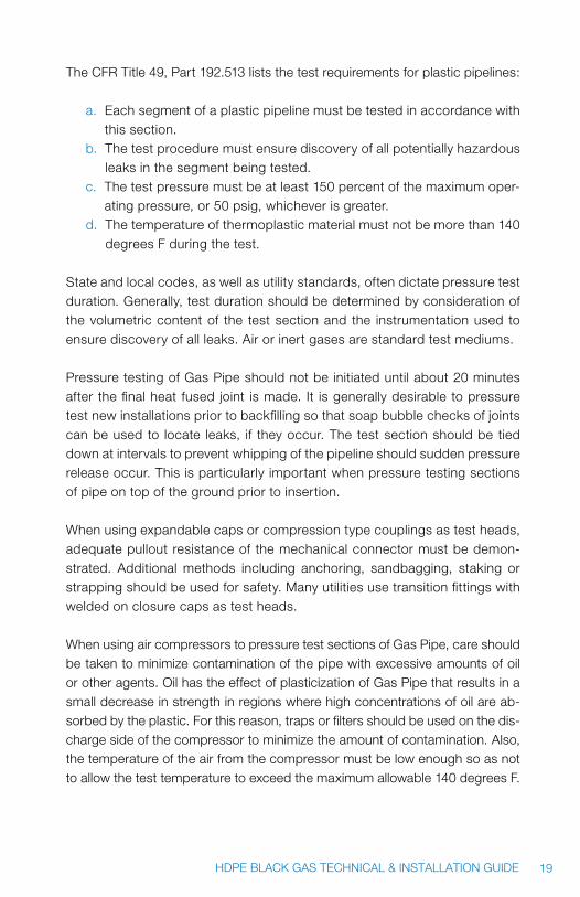
The CFR Title 49, Part 192.513 lists the test requirements for plastic pipelines:
a. Each segment of a plastic pipeline must be tested in accordance with this section.
b. The test procedure must ensure discovery of all potentially hazardous leaks in the segment being tested.
c. The test pressure must be at least 150 percent of the maximum oper-ating pressure, or 50 psig, whichever is greater.
d. The temperature of thermoplastic material must not be more than 140 degrees F during the test.
State and local codes, as well as utility standards, often dictate pressure test duration. Generally, test duration should be determined by consideration of the volumetric content of the test section and the instrumentation used to ensure discovery of all leaks. Air or inert gases are standard test mediums.
Pressure testing of Gas Pipe should not be initiated until about 20 minutes after the final heat fused joint is made. It is generally desirable to pressure test new installations prior to backfilling so that soap bubble checks of joints can be used to locate leaks, if they occur. The test section should be tied down at intervals to prevent whipping of the pipeline should sudden pressure release occur. This is particularly important when pressure testing sections of pipe on top of the ground prior to insertion.
When using expandable caps or compression type couplings as test heads, adequate pullout resistance of the mechanical connector must be demon-strated. Additional methods including anchoring, sandbagging, staking or strapping should be used for safety. Many utilities use transition fittings with welded on closure caps as test heads.
When using air compressors to pressure test sections of Gas Pipe, care should be taken to minimize contamination of the pipe with excessive amounts of oil or other agents. Oil has the effect of plasticization of Gas Pipe that results in a small decrease in strength in regions where high concentrations of oil are ab-sorbed by the plastic. For this reason, traps or filters should be used on the dis-charge side of the compressor to minimize the amount of contamination. Also, the temperature of the air from the compressor must be low enough so as not to allow the test temperature to exceed the maximum allowable 140 degrees F.

20 HDPE BLACK GAS TECHNICAL & INSTALLATION GUIDE
When time testing large volume sections of Gas Pipe, the operator should be aware of the creep characteristics of plastic pipe and the effects of temperature change. After initial pressurization, polyethylene pipe may continue to expand slightly, causing a noticeable drop in gauge reading that will stabilize after a few minutes. A long-term reading should be initiated when the stabilization point has been reached. Of course, any heating and cooling of the test medium as in an overnight test will affect pressure readings, which could conceivably mask or falsely indicate slow leaks. No specific guidelines can be given, as readings would vary greatly depending on volume and temperature characteristics.
It is occasionally necessary to use gaseous leak detection tracers to locate leaks in a buried system. Commercial odorants in liquid form should not be injected directly into the Gas System because they can temporarily affect the strength of polyethylene. Odorants should be vaporized prior to injection. When bar-holes are sunk to provide a path to the surface for the tracers, care should be taken to avoid puncturing the buried pipeline.
3.16 SAFETy AND FIELD PRECAUTIONS
1. WaRning: Treat electrical tools as potential sources of ignition and fol-low standard safety procedures for working in explosive atmospheres.
2. WaRning: Only properly trained and qualified personnel should make fusions.
3. WaRning: Wear suitable gloves and eye protection. 4. WaRning: Temperature of fusion tools should be checked to be sure
that they conform to the recommended operating temperature range. 5. WaRning: When breaking down bulk packs, take care to stand clear of
pipe while strapping is being cut. Coiled HDPE pipe may contain energy as in a spring. Both the straps and the pipe may spring outward when the strap is cut and could cause severe injury. All safety precautions and proper equipment is required.
6. WaRning: Before cutting coiled pipe, restrain both sides of cut. Pipe is under tension. Unrestrained pipe can spring back forcibly while being cut and could cause personal injury.
7. WaRning: Understand and follow all equipment manufacturer’s recom-mendations and guidelines.

21HDPE BLACK GAS TECHNICAL & INSTALLATION GUIDE
3.17 HEATING TOOL MAINTENANCE
Clean heater adaptors carefully before and after each fusion. Remove any residual polyethylene using a clean non-synthetic cloth. Never use metal ob-jects to clean heater adaptors because they can damage the surface.
The heating tool temperature recommendations shown in this bulletin rep-resent the temperature on the surface of the heater adaptors that actually contact the pipe or fitting. This temperature should be monitored daily to ensure compliance with recommendations.
The operator can usually expect the tool thermometer to indicate a higher tem-perature than specified in order to achieve the correct surface temperature. In addition, the operator will normally encounter variations in heater adaptor tem-perature due to different adaptor configurations. In these cases, the adaptor having the lower temperature should be set at the recommended temperature.
4.0 FUSIOn PrOCEDUrES
WaRning: Understand and follow all equipment manufacturers’ recom-mendations and guidelines.
4.1 SOCKET FUSION
4.1.1 EqUIPMENT
1. Pipe or tubing cutter2. Cold ring3. Depth gauge4. Chamfering tool5. Heating tool6. Female and male heater adaptors7. Fitting puller8. Clean non-synthetic cloth
22 HDPE BLACK GAS TECHNICAL & INSTALLATION GUIDE
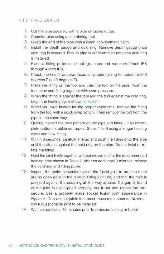
4.1.2 PROCEDURES
1. Cut the pipe squarely with a pipe or tubing cutter. 2. Chamfer pipe using a chamfering tool. 3. Clean the end of the pipe with a clean non-synthetic cloth.4. Install the depth gauge and cold ring. Remove depth gauge once
cold ring is secured. Ensure pipe is sufficiently round once cold ring is installed.
5. Place a fitting puller on couplings, caps and reducers 2-inch IPS through 4-inch IPS.
6. Check the heater adaptor faces for proper joining temperature 500 degrees F (± 10 degrees F).
7. Place the fitting on the tool and then the tool on the pipe. Push the tool, pipe and fitting together with even pressure.
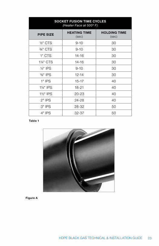
8. When the fitting is against the tool and the tool against the cold ring, begin the heating cycle shown in Table 1.
9. When you have heated for the proper cycle time, remove the fitting from the tool with a quick snap action. Then remove the tool from the pipe in the same way.
10. quickly inspect the melt pattern on the pipe and fitting. If an incom-plete pattern is obtained, repeat Steps 1 to 9 using a longer heating cycle and new fitting.
11. Within 3 seconds, carefully line up and push the fitting onto the pipe until it bottoms against the cold ring on the pipe. Do not twist or ro-tate the fitting.
12. Hold the joint firmly together without movement for the recommended holding time shown in Table 1. After an additional 3 minutes, release the cold ring and fitting puller.
13. Inspect the entire circumference of the fused joint to be sure there are no open gaps in the pipe to fitting juncture, and that the melt is pressed against the coupling all the way around. If a gap is found or the joint is not aligned properly, cut it out and repeat the pro-cedure. See a properly made socket fusion joint appearance in Figure A. Only accept joints that meet these requirements. Never al-low a questionable joint to be installed.
14. Wait an additional 10 minutes prior to pressure testing or burial.
23HDPE BLACK GAS TECHNICAL & INSTALLATION GUIDE
Socket FuSion time cycleS (Heater Face at 500º F)
PiPe SizeHeating time
(sec)HolDing time
(sec)
½" CTS 9-10 30
¾" CTS 9-10 30
1" CTS 14-16 30
1¼" CTS 14-16 30
½" IPS 9-10 30
¾" IPS 12-14 30
1" IPS 15-17 40
1¼" IPS 18-21 40
1½" IPS 20-23 40
2" IPS 24-28 40
3" IPS 28-32 50
4" IPS 32-37 50
table 1
Figure a
24 HDPE BLACK GAS TECHNICAL & INSTALLATION GUIDE
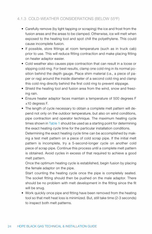
4.1.3 COLD-WEATHER CONSIDERATIONS (BELOW 55ºF)
• Carefullyremove(bylighttappingorscraping)theiceandfrostfromthefusion areas and the areas to be clamped. Otherwise, ice will melt when exposed to the heating tool and spot chill the polyethylene. This could cause incomplete fusion.
• If possible, store fittings at room temperature (such as in truck cab)prior to use. This will reduce fitting contraction and make placing fitting on heater adaptor easier.
• Coldweatheralsocausespipecontractionthatcanresultinalooseorslipping cold ring. For best results, clamp one cold ring in its normal po-sition behind the depth gauge. Place shim material (i.e., a piece of pa-per or rag) around the inside diameter of a second cold ring and clamp this cold ring directly behind the first cold ring to prevent slippage.
• Shieldtheheatingtoolandfusionareafromthewind,snowandfreez-ing rain.
• Ensureheateradaptorfacesmaintainatemperatureof500degreesF±10 degress F.
• Thelengthofcyclenecessarytoobtainacompletemeltpatternwillde-pend not only on the outdoor temperature, but also on wind conditions, pipe contraction and operator technique. The maximum heating cycle times shown in Table 1 should be used as a starting point for determining the exact heating cycle time for the particular installation conditions. Determining the exact heating cycle time can be accomplished by mak-ing a test melt pattern on a piece of cold scrap pipe. If the initial melt pattern is incomplete, try a 5-second-longer cycle on another cold piece of scrap pipe. Continue this process until a complete melt pattern is obtained. Avoid cycles in excess of that required to achieve a good melt pattern. Once the optimum heating cycle is established, begin fusion by placing the female adaptor on the pipe. Start counting the heating cycle once the pipe is completely seated. The socket fitting should then be pushed on the male adaptor. There should be no problem with melt development in the fitting since the fit will be snug.
• Workquicklyoncepipeandfittinghavebeenremovedfromtheheatingtool so that melt heat loss is minimized. But, still take time (2-3 seconds) to inspect both melt patterns.

25HDPE BLACK GAS TECHNICAL & INSTALLATION GUIDE
4.2 BUTT FUSION
In addition to the following procedure, JM Eagle™ also has tested and endorses TR-33, the generic butt fusion procedure that is available at www.plasticpipe.org.
4.2.1 HEATING TIME
The heating time for virtually all large diameter pipe is determined by visually observing the melt bead during heating. For sizes 8 inches and larger, a bead width of three sixteenths of an inch to one quarter of an inch is recommended.
4.2.2 INTERFACIAL PRESSURE
The interfacial pressure for butt joints has been expanded to 60 to 90 psi. For hydraulic machines, the fusion force is determined by multiplying the interfacial pressure times the calculated pipe end area. The gauge pressure is theoretical; the internal and external drag needs to be added to this figure to obtain the actual fusion pressure required by the machine. Contact the machine manufacturer for set-up details.
4.2.3 HOLDING & COOLING TIME
The molten joint must be held immobile under pressure until cooled ad-equately to develop its strength. Due to the heavy weight of large diameter, heavy (lower SDR number) wall pipe, the newly made joint must be able to withstand the added stress of pipe removal from the machine. The fusion force should be held in the machine until the surface of the bead is cool to the touch. Ambient field conditions may require a cooling time of 30 to 90 seconds per inch of pipe diameter to achieve the cool temperature for re-moval from the machine. Pulling, installation, or rough handling of the pipe should be avoided for an additional 30 minutes.
WaRning: Understand and follow all equipment manufacturer’s recom-mendations and guidelines.
26 HDPE BLACK GAS TECHNICAL & INSTALLATION GUIDE
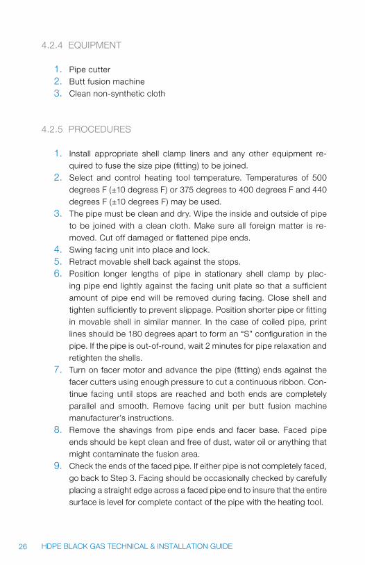
4.2.4 EqUIPMENT
1. Pipe cutter2. Butt fusion machine3. Clean non-synthetic cloth
4.2.5 PROCEDURES
1. Install appropriate shell clamp liners and any other equipment re-quired to fuse the size pipe (fitting) to be joined.
2. Select and control heating tool temperature. Temperatures of 500 degrees F (±10 degress F) or 375 degrees to 400 degrees F and 440 degrees F (±10 degrees F) may be used.
3. The pipe must be clean and dry. Wipe the inside and outside of pipe to be joined with a clean cloth. Make sure all foreign matter is re-moved. Cut off damaged or flattened pipe ends.
4. Swing facing unit into place and lock. 5. Retract movable shell back against the stops. 6. Position longer lengths of pipe in stationary shell clamp by plac-
ing pipe end lightly against the facing unit plate so that a sufficient amount of pipe end will be removed during facing. Close shell and tighten sufficiently to prevent slippage. Position shorter pipe or fitting in movable shell in similar manner. In the case of coiled pipe, print lines should be 180 degrees apart to form an “S” configuration in the pipe. If the pipe is out-of-round, wait 2 minutes for pipe relaxation and retighten the shells.
7. Turn on facer motor and advance the pipe (fitting) ends against the facer cutters using enough pressure to cut a continuous ribbon. Con-tinue facing until stops are reached and both ends are completely parallel and smooth. Remove facing unit per butt fusion machine manufacturer’s instructions.
8. Remove the shavings from pipe ends and facer base. Faced pipe ends should be kept clean and free of dust, water oil or anything that might contaminate the fusion area.
9. Check the ends of the faced pipe. If either pipe is not completely faced, go back to Step 3. Facing should be occasionally checked by carefully placing a straight edge across a faced pipe end to insure that the entire surface is level for complete contact of the pipe with the heating tool.

27HDPE BLACK GAS TECHNICAL & INSTALLATION GUIDE
10. Bring the faced pipe ends together to ensure that the pipe will not slip in the shells. Check for high-low alignment between pipe ends. Tighten the inside clamp on the high side to align pipe ends as closely as possible. Never loosen the low side clamp. If the pipe ends are not aligned or if gaps are present, adjust the pipe in the shells and go back to Step 3.
11. Retract the shells and position the heating tool between the pipe ends. 12. Move the pipe and/or the fitting ends against the heating tool firmly to
assure complete contact; then relax to slight contact pressure only. 13. Heating guidelines shown in Table 2 should develop an approximate
bead width of the size shown in Table 3. Heating cycle starts when a complete, uniform bead of molten material is visible around the en-tire circumference of both ends. It is optional to develop melt based on visual appearance provided that Bead Width guidelines shown in Table 3 are attained.
14. At the end of the heating cycle, quickly retract the pipe shelI clamps to snap the heater away from the pipe ends. Remove the heater with-out touching the pipe (if melted material is pulled off the pipe ends, allow the pipe to cool and then repeat the entire procedure). Bring the melted ends together rapidly (do not slam) to develop a double roll back of each bead onto the pipe. Use only enough pressure to form a double rollback bead. This operation should take no longer than three seconds.
note: Hydraulic butt fusion machines should be set using an interfacial pressure of 60 to 90 psi. Refer to butt fusion machine manufacturer’s recom-mendation for specific machine settings.
15. Maintain pressure for the “Holding Time Cycle” shown in Table 2. 16. Release pressure and allow joint to cool in the machine for an addi-
tional 3 minutes. Open shells and remove the pipe from the machine handling it with care.
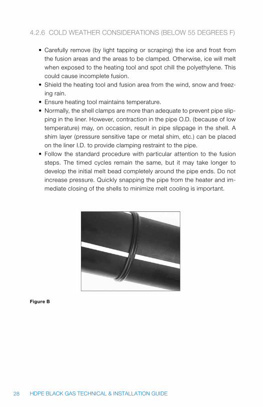
17. Inspect the entire circumference of the fused joint for uniformity in size and shape. Each bead width should be the approximate dimen-sions shown in Table 3. See Figure B for a properly made butt fusion joint. Only accept joints meeting these requirements. Never allow a questionable joint to be installed.
18. visually mitered joints (angled, offset) shoud be cut out and re-fused.19. Allow further cooling of 20 minutes or until bead is not hot to the
touch, before subjecting the pipe to rough handling.
28 HDPE BLACK GAS TECHNICAL & INSTALLATION GUIDE
4.2.6 COLD WEATHER CONSIDERATIONS (BELOW 55 DEGREES F)
• Carefully remove (by light tappingorscraping) the iceand frost fromthe fusion areas and the areas to be clamped. Otherwise, ice will melt when exposed to the heating tool and spot chill the polyethylene. This could cause incomplete fusion.
• Shieldtheheatingtoolandfusionareafromthewind,snowandfreez-ing rain.
• Ensureheatingtoolmaintainstemperature.• Normally,theshellclampsaremorethanadequatetopreventpipeslip-
ping in the liner. However, contraction in the pipe O.D. (because of low temperature) may, on occasion, result in pipe slippage in the shell. A shim layer (pressure sensitive tape or metal shim, etc.) can be placed on the liner I.D. to provide clamping restraint to the pipe.
• Follow the standard procedure with particular attention to the fusionsteps. The timed cycles remain the same, but it may take longer to develop the initial melt bead completely around the pipe ends. Do not increase pressure. quickly snapping the pipe from the heater and im-mediate closing of the shells to minimize melt cooling is important.
Figure B
29HDPE BLACK GAS TECHNICAL & INSTALLATION GUIDE
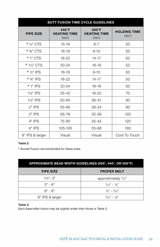
Butt FuSion time cycle guiDelineS
PiPe Size440°F
Heating time (sec)
500°F Heating time
(sec)
HolDing time (sec)
* ½" CTS 15-18 6-7 50
* ¾" CTS 16-19 8-10 50
* 1" CTS 18-22 14-17 50
* 1¼" CTS 20-24 16-19 50
* ½" IPS 16-19 8-10 50
* ¾" IPS 18-22 14-17 50
* 1" IPS 20-24 16-19 50
1¼" IPS 35-42 18-22 70
1½" IPS 50-60 26-31 90
2" IPS 55-66 28-34 90
3" IPS 65-78 30-36 120
4" IPS 75-90 35-42 120
6" IPS 105-126 55-66 180
8" IPS & larger visual visual Cool To Touch
table 2
* Socket Fusion recommended for these sizes.
aPPRoximate BeaD WiDtH guiDelineS (400°, 440°, oR 500°F)
PiPe Size PRoPeR melt
1¼"- 3" approximately 1/16"
3" - 6" 1/16" - 1/8"
6" - 8" 1/8" - 3/16"
8" IPS & larger 3/16" - ¼"
table 3Each bead after fusion may be slightly wider than those in Table 3.

30 HDPE BLACK GAS TECHNICAL & INSTALLATION GUIDE
4.3 SADDLE OR SIDEWALL FUSION PROCEDURE
In addition to the following procedure, JM Eagle™ also has tested and en-dorses TR-41, the generic fusion procedure that is available from PPI at www.plasticpipe.org.
An application tool must be used when making saddle fusion joints. Follow the tool manufacture’s operating procedures for proper use of the tool.
WaRning: Understand and follow all equipment manufacturer’s recom-mendations and guidelines.
4.3.1 EqUIPMENT
1. Application Tool2. Heating Tool3. Appropriate size saddle heater adapters4. 50- to 60-grit utility cloth5. Clean non-synthetic cloth or lint-free paper towel
4.3.2 PROCEDURE
Place the tool on the main. It must be able to straighten, round and support the main during the heating, joining, and holding steps. A bolster plate is rec-ommended for 6-inch IPS and smaller mains. Heating times start when the fitting and pipe are firmly seated against the heater faces. During heating, the heating tool may be rocked slightly, about 2 degrees, to seek its own align-ment and to assure full contact with the main.
Clean main and fitting. Ensure that heater adaptor surfaces are at 500 de-grees F ± 10 degrees F and the correct heating faces are installed. Roughen pipe main and fitting fusion surface with 50- to 60-grit utility cloth. Brush any residue away with a clean, dry non-synthetic cloth or paper towel.
Insert fitting into application unit, confirm proper alignment, then secure fit-ting tightly in unit. Center heater tool under the fitting, then apply and main-tain firm, continuous pressure until a complete melt bead is seen on the
31HDPE BLACK GAS TECHNICAL & INSTALLATION GUIDE
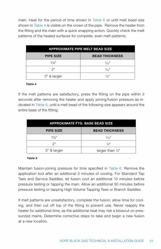
main. Heat for the period of time shown in Table 6 or until melt bead size shown in Table 4 is visible on the crown of the pipe. Remove the heater from the fitting and the main with a quick snapping action. quickly check the melt patterns of the heated surfaces for complete, even melt patterns.
aPPRoximate PiPe melt BeaD Size
PiPe Size BeaD tHickneSS
1¼" 1/32"
2" 1/16"
3" & larger 1/8"
table 4
If the melt patterns are satisfactory, press the fitting on the pipe within 3 seconds after removing the heater and apply joining/fusion pressure as in-dicated in Table 6, until a melt bead of the following size appears around the entire base of the fitting:
aPPRoximate Ftg. BaSe BeaD Size
PiPe Size BeaD tHickneSS
1¼" 1/16"
2" 1/8"
3" & larger larger than 1/8"
table 5
Maintain fusion-joining pressure for time specified in Table 6. Remove the application tool after an additional 3 minutes of cooling. For Standard Tap Tees and Service Saddles, let fusion cool an additional 10 minutes before pressure testing or tapping the main. Allow an additional 30 minutes before pressure testing or tapping High volume Tapping Tees or Branch Saddles.
If melt patterns are unsatisfactory, complete the fusion; allow time for cool-ing, and then cut off top of the fitting to prevent use. Never reapply the heater for additional time, as the additional heat may risk a blowout on pres-surized mains. Determine corrective steps to take and begin a new fusion at a new location.
32 HDPE BLACK GAS TECHNICAL & INSTALLATION GUIDE
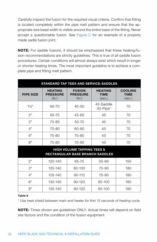
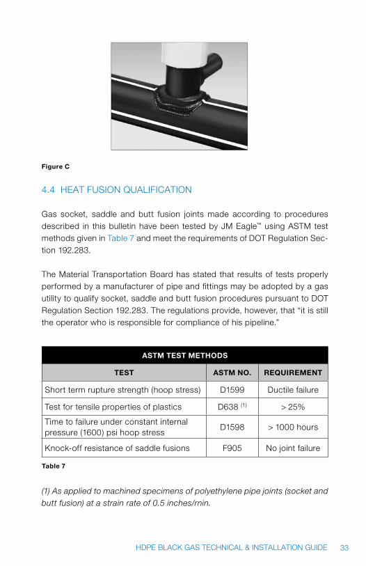
Carefully inspect the fusion for the required visual criteria. Confirm that fitting is located completely within the pipe melt pattern and ensure that the ap-propriate size bead width is visible around the entire base of the fitting. Never accept a questionable fusion. See Figure C for an example of a properly made sadle fusion joint.
note: For saddle fusions, it should be emphasized that these heating/fu-sion recommendations are strictly guidelines. This is true of all saddle fusion procedures. Certain conditions will almost always exist which result in longer or shorter heating times. The most important guideline is to achieve a com-plete pipe and fitting melt pattern.
StanDaRD taP teeS anD SeRVice-SaDDleS
PiPe SizeHeating
PReSSuRe (lb/)
FuSion PReSSuRe
(lb/)
Heating time (sec.)
cooling time (sec.)
1¼" 60-70 40-5045-Saddle 30-Pipe*
70
2" 65-75 45-65 45 70
3" 70-80 50-70 45 70
4" 70-80 60-80 45 70
6" 75-80 70-80 45 70
8" 75-80 70-80 45 70
HigH Volume taPPing teeS & RectangulaR BaSe BRancH SaDDleS
2" 120-140 65-75 55-65 150
3" 125-140 80-100 75-90 180
4" 125-140 90-110 75-90 180
6" 130-140 90-120 85-100 180
8" 130-140 90-120 85-100 180
table 6
* Use heat shield between main and heater for first 15 seconds of heating cycle.
note: Times shown are guidelines ONLy. Actual times will depend on field site factors and the condition of the fusion equipment
33HDPE BLACK GAS TECHNICAL & INSTALLATION GUIDE
Figure c
4.4 HEAT FUSION qUALIFICATION
Gas socket, saddle and butt fusion joints made according to procedures described in this bulletin have been tested by JM Eagle™ using ASTM test methods given in Table 7 and meet the requirements of DOT Regulation Sec-tion 192.283.
The Material Transportation Board has stated that results of tests properly performed by a manufacturer of pipe and fittings may be adopted by a gas utility to qualify socket, saddle and butt fusion procedures pursuant to DOT Regulation Section 192.283. The regulations provide, however, that “it is still the operator who is responsible for compliance of his pipeline.”
aStm teSt metHoDS
teSt aStm no. ReQuiRement
Short term rupture strength (hoop stress) D1599 Ductile failure
Test for tensile properties of plastics D638 (1) > 25%
Time to failure under constant internal pressure (1600) psi hoop stress
D1598 > 1000 hours
Knock-off resistance of saddle fusions F905 No joint failure
table 7
(1) As applied to machined specimens of polyethylene pipe joints (socket and butt fusion) at a strain rate of 0.5 inches/rnin.
34 HDPE BLACK GAS TECHNICAL & INSTALLATION GUIDE
4.4.1 DOT REGULATIONS FOR PROCEDURES AND PERSONNEL qUALIFICATION
The DOT has ruled that, effective July 1, 1980, Part 192 of Title 49 of the Code of Federal Regulations is amended as follows (for heat fusion joints):
Section 192.283 Plastic Pipe; Qualifying Joining Procedures-Heat Fusion Before any written procedure established under Section 192.273(b) is used for making plastic pipe joints by a heat fusion method, the procedure must be qualified by subjecting specimen joints made according to the procedure to the following tests:
1. The burst test requirements of Paragraph 6.6 (Sustained Pressure Test) or Paragraph 6.7 (Minimum Hydrostatic Burst Pressure) of ASTM D2513(2).
2. For procedures intended for lateral pipe connections subject a speci-men joint made from pipe sections joined at right angles according to the procedure to a force on the lateral pipe until failure occurs in the specimen (ASTM F905). If failure initiates outside the joint area, the procedure qualifies for use; and
3. For procedures intended for nonlateral pipe connections, follow the tensile test requirements of ASTM D638, except that the test may be conducted at ambient temperature and humidity. If the specimen elongates no less than 25 percent or failure initiates outside the joint area, the procedure qualifies for use.
Section 192.285 Plastic Pipe; Qualifying Persons to make Joints 1. No person may make a plastic pipe joint unless that person has been
qualified under the applicable procedure by: a. Appropriate training or experience in the use of the procedure, and b. Making a specimen joint from pipe sections joined according to the
procedure that passes the inspection and test set forth below. 2. The specimen joint must be: a. visually examined during and after assembly or joining and found to
have the same appearance as a joint or photographs of a joint that is acceptable under the procedure; and
b. In the case of a heat fusion ... joint: i. Tested under Section 192.283; ii. Examined by ultrasonic inspection and found not to contain flaws that
would cause failure; or
35HDPE BLACK GAS TECHNICAL & INSTALLATION GUIDE
iii. Cut into at least 3 longitudinal straps, each of which is: a. visually examined and found not to contain voids or discontinui-
ties on the cut surface area; and b. Deformed by bending, torque, or impact, and if failure occurs, it
must not initiate in the joint area.
4.4.2 PROCEDURES FOR HEAT FUSION qUALIFICATION
1. Prepare fusion joint as described previously in the “Fusion Proce-dures” section of this manual. Allow joint to cool one hour.
2. Compare the outside appearance of joint with photograph illustrating the correct procedure.
3. Section the joint axially into at least three straps (1-inch wide) to ex-pose the bond area. Leave approximately 8 inches of pipe on both sides of the joint.
4. Inspect the fusion to verify:
Socket Fusion •Completemeltdevelopment•Nogapsorvoids•Externalmeltpressedagainstcoupling•Bondlength•Properalignment
Butt Fusion •Completeanduniformmeltbeads•Meltbeadrolledbacktopipe•Nogapsorvoids•Properalignment•Completefacing•Visuallymiteredjoints(angled,offset)shouldbecutoutandre-fused.
Saddle Fusion •Completepipemeltpattern•Nogapsorvoids•Completemeltdevelopmentaroundbaseoffitting•Fittingplacementinpipemeltpattern•Properlypreparedpipesurface
36 HDPE BLACK GAS TECHNICAL & INSTALLATION GUIDE
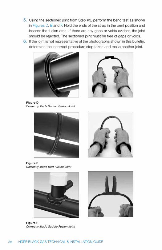
5. Using the sectioned joint from Step #3, perform the bend test as shown in Figures D, E and F. Hold the ends of the strap in the bent position and inspect the fusion area. If there are any gaps or voids evident, the joint should be rejected. The sectioned joint must be free of gaps or voids.
6. If the joint is not representative of the photographs shown in this bulletin, determine the incorrect procedure step taken and make another joint.
Figure D Correctly Made Socket Fusion Joint
Figure e Correctly Made Butt Fusion Joint
Figure F Correctly Made Saddle Fusion Joint
37HDPE BLACK GAS TECHNICAL & INSTALLATION GUIDE
5.0 SQUEEZE-OFF
WaRning: Understand and follow all equipment manufacturer’s recom-mendations and guidelines.
Effective flow control is a basic requirement in gas distribution systems. This is accomplished with the Gas Pipe in two ways. The primary method of flow control should be those installed system valves that are available. Secondly squeeze-off using suitable equipment can be used to control flow or isolate a section of pipe. Also, squeeze-off is frequently used to control flow for emergency repairs or during certain pipeline or branch extension operations.
This section describes equipment and explains proper procedures and pre-cautions for effectively and safely squeezing off Gas Pipe for flow control. The pressure rating of the pipe is retained if the recommended procedures and equipment are used.
5.1 TOOLS
Squeeze units suitable for use on Gas Pipe consist of steel bars and a me-chanical or hydraulic means of forcing the bars together. These units are de-signed to squeeze Gas Pipe until the inside surfaces meet. This adequately controls gas flow although a bubble tight seal is not always obtained. A posi-tive locking mechanism should be available.
caution: To assure flow control, yet prevent damage to the pipe, tools have mechanical stops to limit the minimum gap between the squeeze bars. Recommended minimum gaps between the squeeze bars for Gas Pipe are based on the formula:
min.gap = (2) (max wall thickness) x (0.7)
In addition to observing the minimum gap distances between bars, the bars themselves should be rounded to prevent pipe damage.
The user also may want to consult the “Standard Guide for Squeeze-Off of Polyolefin Gas Pressure Pipe and Tubing,” Designation F1041, issued by ASTM.
38 HDPE BLACK GAS TECHNICAL & INSTALLATION GUIDE
5.2 PRECAUTIONS FOR SqUEEZE-OFF
• Certainprecautionsshouldbe taken topreventdamage to thesqueezetools or to Gas Pipe during squeeze-off in recognition of the large forces required for flow control, particularly in large main sizes. Damage to the pipe from improper squeeze-off procedures may cause eventual failure.
• Makecertainthepipeiscenteredandsquaredinthesqueezetool.It isimportant that the pipe be free to spread as it flattens. Failure to do so may prevent flow control or result in damage to the pipe or the tool.
• Locate the squeeze point at least three pipe diameters away from thenearest fitting or butt-fused joint. Failure to do so may result in damage to the fittings or joints.
• Squeeze-offGasPipeonlyonceinthesameplace.Itispossibleforscaleor other metal particles contained within the gas flow to become trapped at the squeeze point. A second squeeze in the immediate area of the first could force these particles to penetrate into or through the pipe wall.
• Alwaysuseasqueezetoolwithgapstopstolimittheamountofsqueezeand use the proper gap stops for the pipe size being squeezed. Using smaller gap stops or otherwise over-squeezing the pipe may result in damage to the pipe or tool.
• Abubbletightflowcontrolwillnotalwaysbeobtainedthroughsqueeze-off. If more complete flow control is required, a valve should be used or additional squeeze tools used in series to supplement each other.
• Closethesqueezetoolsuntilflowiscontrolledoruntilthegapstopsmakecontact. Do not use extension levers or “cheater bars”, or otherwise abuse the tools in trying to effect a squeeze-off. Such abuse may overstress the tool and result in failure of the tool and release of the gas flow. Any dam-aged tool should be repaired or replaced before use for squeeze-off of Gas Pipe.
• SqueezeGasPipeslowlyorusemomentarypauses in theoperation toallow for pipe relaxation and reduction in resistance to closure. This is particularly helpful in larger diameters or when the pipe becomes stiffer in cold weather.
• A release rate of 0.5 inches/minute or less is recommended by ASTMF1041 based on a GRI/Battelle Study, “Effect of Squeeze-Off Practices and Parameters on PE Gas Pipe Damage.” *
* Twelfth Plastic Fuel Gas Pipe Proceedings, pp. 228-242 (1991).

39HDPE BLACK GAS TECHNICAL & INSTALLATION GUIDE
5.3 STATIC ELECTRICITy
WaRning: Treat electrical tools as potential sources of ignition and follow standard safety procedures for working in explosive atmospheres.
Emergency flow control situations requiring squeeze-off may involve working in the vicinity of blowing gas. The possibility and potential hazard of static electricity should be considered and the company standards on bell-hole safety followed.
Because static electricity can build up on any non-conductor such as plastic pipe, there is a possibility of a spark discharge of sufficient energy to cause ignition if the proper air/gas mixture is present. It is also possible for repair crews to receive shocks even though ignition does not occur. Therefore, a study was made with a major gas utility to define the nature of static charge buildup on polyethylene pipe. The results of that study indicated that:
1. Potential for ignition is present if all three of the following conditions are present: (a) there is sufficient gas flow to cause extensive turbulence; (b) rust particles or other foreign particles are present in the gas; (c) the charge is present at a point where a combustible air/gas mixture is present.
2. During the study, voltages over 30,000 volts were generated, but no ignitions occurred. The location of the measured charge (on the inner wall of the pipe several inches from the opening) was such that there is some doubt that it is present at a point where the combustible air/gas mixture is also present.
3. Although ignition was not obtained, it is clear that under certain con-ditions high static charges can be developed and static discharge is a possible ignition source.
Some users have taken precautions to dissipate the charge and minimize the possibility of an ignition and maximize the personal safety of the crew. The objective is to provide a path to ground for any static charge. These precautions have included: • Beforepersonnelarepermittedinthebellhole,afinewatersprayisapplied
over the entire area including all exposed pipe and dirt. • Thepipe iskeptwetduringthesqueeze-offprocedureuntilsqueeze-off
is complete.
• A wet rag is applied to the pipe surface to provide dissipation of staticcharge to ground.
• Infreezingweather,a50/50solutionofantifreezeandwaterissometimesnecessary.
Squeezing the pipe used for gas distribution causes an increase in the veloc-ity of flowing gas and thus possible increase in static charge development. Therefore, it is suggested that squeeze-off be done in a separate bell-hole remote to the leak whenever possible.
Additional information on static electricity is summarized in the report, “Static Electricity Considerations in Repair of Polyethylene Pipe Systems,” available from JM Eagle™ sales representatives, and in the AGA “Plastic Pipe Manual for Gas Service.”
JM Eagle™ gas pipe conforms to the requirements outlined in ASTM D 2513 specifications for Thermoplastic Gas Pressure Pipe, Tubing and Fittings, which is necessary to meet the Pipeline Safety Regulations Part 192, Mini-mum Safety Standards for the transport of natural gas.
Gas pipe products (previously produced by US Poly) are currently manufac-tured by JM Eagle™.
This guide is meant as an explanatory supplement to the materials above on how to install JM Eagle™ Black Gas Pipe under normal or average conditions so as to comply with Standard Laying Specifications. Any discrepancies between the above standards and the written information contained herein should be brought to the attention of Product Assurance immediately for resolution, prior to any actions by either contractor, engineer or municipality.
This guide is not intended to supply design information nor to assume the responsibility of the engineer (or other customer representative) in establishing procedures best suited to individual job conditions so as to attain satisfac-tory performance.
Engineers, superintendents, contractors, foremen and laying crews will find out much to guide them. This booklet will also be of help in determining pipe needs when ordering.

NOTES:
Building essentials for a better tomorrow
revised January 2009 JME-014B
© J-M Manufacturing Co., Inc.
5200 West Century BlvdLos Angeles, CA 90045T: 800.621.4404 F: 800.451.4170
Nine Peach Tree Hill RoadLivingston, NJ 07039 T: 973.535.1633 F: 973.533.4185
www.JMEagle.com
GLOBaL HEaDQUartErS: rEGIOnaL OFFICE: