bk130-1
TRANSCRIPT
AC DIELECTRIC TEST SET
Model Number BK130-1 Serial Number
Version 1.0
HJP/slu December 6, 2002

TABLE OF CONTENTS
Section Number DANGER TITLE PAGE 1 TECHNICAL SPECIFICATIONS 2 UNCRATING PROCEDURE 3 ELECTRICAL SET-UP/GROUND GUARD CONNECTIONS 4 OPERATING INSTRUCTIONS 5 CALIBRATION 6 TROUBLESHOOTING 7 STORAGE OF EQUIPMENT 8 CIRCUIT DIAGRAM SYMBOLS 9 ELECTRICAL DIAGRAMS 10 TEST REPORT 11 PARTS ORDERING INFORMATION 12 PARTS LIST 13 RECOMMENDED SPARE PARTS 14 WARRANTY 15 RETURNED MATERIAL 16

1-1
AC DIELECTRIC TEST SET Model Number BK130-1 Serial Number Customer Customer's Purchase Order Number Manufacturing Date

2-1 TECHNICAL SPECIFICATIONS
Input 120 volts, 60 Hz, single phase, 8 amperes Output Rating
130 kilovolts, 8.33 milli-amperes maximum – 1 kVA 130 kilovolts, 11.8 milli-amperes maximum – 1.4 kVA Duty Cycle 1 Hour ON / 1 Hour OFF at 8.33 mA 5 Minutes ON / 15 Minutes OFF at 11.8 mA Type of Cooling Uncirculated air / oil Distortion Less than 5 percent Impedance Less than 15 percent at rated current Operating Ambient Temperature 0-40 degrees Celsius Output Termination High Voltage Toroid Metering
Output Voltmeter: 3 ½ Digit LCD Meter, Accuracy ± 1% of reading from 13-130kV. (Peak Responding Calibrated to RMS Value.) Output Currentmeter: 3 ½ Digit LCD Meter, Accuracy ± 1% of Full Scale. Ranges of 0-200µA, 0-2mA, 0-20mA
Sizes and Weights Control section: 21”(533 mm) W x17”(432 mm) D x13”(330 mm) H;
Weight: 40 lbs (18.2 kg.)* Transformer: 15"(381 mm) W x 16 "(407 mm) D x 27"(686 mm) H.;
Weight: 132 lbs. (59.9 kg.) Cart: 56 lbs. (25.4 kg.) Standard Cables: 5 lbs. (2.3 kg.) Total unit weight including cart and cables: 233 lbs. (105.7 kg.)* *Add 3 lbs for 220V

3-1 UNCRATING PROCEDURE
1. Exercise care in removing shipping materials so as not to damage unit. 2. Perform visual inspection to determine if unit was damaged during shipment. If there are
any signs of physical damage (such as dents, scratches, oil leaks), contact the factory before proceeding.

4-1 ELECTRICAL SET-UP
WARNING: Be sure the Main Power plug is unplugged before proceeding. 1. Remove High Voltage transformer from transit cart (if supplied) at desired location. 2. Locate the desired location for the test set controls. Prepare the main power input cable for
plugging in to the proper facility power (i.e., 120 volts AC, 230 volts AC, etc.). Leave plug unconnected at this time.
3. Connect a sufficient ground from the ground stud to a proper facility ground using a low
inductance cable with a minimum rating equal to the input rating of the test set.
4. External Interlock If an external interlock is not to be used, plug the connector as supplied into the socket on the control panel marked SX1. If the external interlock is to be used, remove the jumper on the removable connector of the external interlock circuit and connect the external security circuit at these points. (NOTE: The external interlock circuit must consist of a closed loop of dead contacts. When the control power is on, the external circuit will be energized with 120 volts AC.)
High Voltage Connection WARNING: Main power circuit breaker on the front panel must be in the OFF position before proceeding. 1. Connect the ground stud located on the base of the H.V. Transformer to facility ground with
low inductance cable or braid.
2. Connect the low potential side of test specimen to the Return terminal. (Refer to Ground-Guard-Return Connections for other connection options). Note: The Jumper Clip on the binding posts on the base of the HV unit must always be connected, either between ground (“GND”) and return (“RTN”) posts or between ground and guard (“GRD”) posts, as appropriate. Do Not operate unit without the Jumper Clip firmly connected.
3. Connect metering cable and power cable (P1 and TX1) (provided) from connectors on
transformer base to connectors on control panel. 4. Connect the high potential side of test specimen to toroid on top of HV tank. 5. Check that Main Power Circuit Breaker on the control unit is off, and then connect input
Main Power Cable to facility power.

4-2
GROUND-GUARD-RETURN CONNECTIONS The base of the High Voltage transformer contains a currentmeter feature useful in measurement of different current sources. 1. Standard Mode (RTN)
The standard configuration is set up to measure the current from the high potential side of the unit under test to ground. This configuration must be used if it is not possible to isolate the low voltage side of the object under test from ground. The low potential side of the unit under test is connected directly to ground. The binding post Jumper Clip is installed between the “GND” and the “RTN” posts on the base of the H. V. Transformer. This measures the output current flowing from the high voltage output through the unit under test to ground and the current meter then senses the return current from ground to the “RTN” terminal of the high voltage transformer.
2. Guard Mode
For test objects that can be fully isolated from ground it may be desirable to use the Guard Mode. In this mode only current passing through the test object will be displayed on the current meter. This will be especially important if very small currents are to be observed. In this mode the current path does not flow directly to ground from the low potential side of the unit under test, but flows through the currentmeter first and then to ground. The connection to be made is (1) connect the low potential side of the unit under test directly to the post marked “RTN” and (2) connect the jumper clip between the “GRD” and “GND” posts. (NOTE: Ensure the “GND” post is grounded.)
If the test specimen is not fully isolated from ground, the current meter will either not work, or not display accurate current readings, and this mode should not be used.

4-3 Figure 1
G U A RD
G ROU ND
R E T U RN
T E S T OB J E C T
A
M E T E RC U R R E NT
H VT R A NS FOR M E R
H IG H VOLT A G E C ONNE C T ION
S T A ND A R D M OD E
G U A RD M OD E
INT E RNA L
H VT R A NS FOR M E R
G U A RD
C U R R E NT
A
M E T E R
G ROU ND
R E T U RN
INT E RNA L
T E S T OB J E C T
H IG H VOLT A G E C ONNE C T ION

5-1 OPERATION INSTRUCTIONS
Caution: This equipment is only to be operated by persons familiar with high voltage testing and safety procedures. 1. Ensure proper electrical set-up has been performed, and that Main Power Circuit Breaker on
Control Panel is Off. 2. Check that Emergency Off switch is pulled up in “ON” position. 3. Check that the Voltage Control dial is set to "0" (zero start position). 4. Select the appropriate currentmeter range for the desired test current (if applicable). 5. Set the Current Trip to the desired current level set point. Setting of "1" will trip off the unit
when drawing approximately 10% of current meter range setting. Setting of "11" will trip off the unit when drawing approximately 110% of current meter range setting.
High Voltage Applied 6. Turn on the front panel circuit breaker. Main Power lamp will illuminate. Ready lamp should
illuminate. If Ready lamp does not illuminate, check Emergency Off switch, Zero Start, External Interlock, and Reset.
7. Press HV On push-button. High voltage ON lamp should illuminate. 8. Rotate the Voltage Control dial and watch the Output Voltmeter and Output Currentmeter
until desired levels are reached. 9. Record data, if desired, and lower the output Voltage Control after testing is completed.
Press HV Off button; high voltage will shut off. Overcurrent Failure 10. If an overcurrent situation occurs, the Reset lamp will illuminate and high voltage will be shut
off. To regain high voltage, the Voltage Control dial must be returned to zero and the Reset button must be depressed (lamp will extinguish).
11. After all testing is completed; turn off the front panel circuit breaker. Remove the input
power cable from the facility power input.

6-1 CALIBRATION
Caution: Calibration should only be done by persons familiar with High Voltage testing and safety procedures. All calibrations have been done at the factory. Periodic calibration of the output voltmeter and output currentmeter should be done approximately every six months. NOTE: Refer to Electrical Diagram Section for schematic pertaining to the model number of your test set. Locating the Calibration Adjustments The calibration points are shown in the following diagram.
1. Output Voltmeter
Connect a precision high voltage voltmeter across the output to ground. Raise the output to approximately 80% of the rated output voltage. Adjust the reading on the panel meter (M2) by means of potentiometer R2 to a corresponding reading. Check at other voltages. Voltmeter is peak responding calibrated to Peak/√2 (RMS equivalent of Peak Value).
6-2
R101 10% Trip
R103 110% Trip
R235 Range Trip
R2 VM
R202 High CM
R203 Med CM
R204 Low CM
CALIBRATION 2. Output Currentmeter
It is necessary to connect adequately rated High Voltage loads ( isolated from ground) to the high voltage unit that will allow each full range current to be drawn at approximately 15% or higher output voltage. This allows sufficient resolution to adjust current levels.
Place Binding Post Configuration in GUARD MODE. (Jumper clip is installed between “GRD” and “GND” posts.) Connect a precision ammeter between the low potential side of the appropriate high voltage load and the “RTN” post. Select the low current meter range. Raise the output to approximately 80% of the range. Adjust the reading on the panel meter (M1) by means of potentiometer R204 to a corresponding reading. Repeat for Medium and High ranges adjusting R203 and R202, respectively. (High Voltage load will need to change when changing range). An optional method is to use current injection between “RTN” and “GND” (Guard Mode). Do not turn High Voltage On for this method!
3. Overcurrent This calibration should not need adjustment (factory adjusted). If the overcurrent circuit is out of calibration, perform the following steps.
a. With unit off, short the output terminal to ground through an appropriate currentmeter.
NOTE: A High Voltage Load will give better resolution and make calibration easier.
b. Set the Current Trip potentiometer on the front panel to "1", and current range switch to High.
c. Turn on HV On and adjust the output current slowly until 10% of rated current (check
nameplate) is displayed on the currentmeter.
d. Adjust potentiometer R101 until the Reset lamp illuminates and high voltage is shut off.
e. Set the Current Trip potentiometer on front panel to "11".
f. Turn on HV On and adjust the output current slowly until 110% of rated current is
displayed on meter.
g. Adjust potentiometer R103 until the Overload lamp illuminates and high voltage is shut off.
h. Repeat step "B" through "G" as necessary until both settings are calibrated.
4. Range Overcurrent. R235 sets an overcurrent for the ranges and should be set to trip at
approximately 112% of medium range full range current.
7-1 TROUBLESHOOTING
General If the controls do not operate properly after having been used according to the instructions, the following hints may help. ♦ Check main facility input power to the test set. ♦ Check all control and switch settings.
♦ Check indicating lamps. (Spare lamps are available through Phenix Technologies.) ♦ Check Fuses
♦ Check operation of circuit breaker (CB1). Main Power lamp should be on. ♦ Check all plug connections, internal and external, on the test set.
Specific Problems 1. High voltage cannot be turned on?
§ Emergency off has been pressed. § External interlock is open. § Voltage Control dial is not in zero start position. § Protection circuit (Current Trip) is not Reset. § Faulty HV On or Off switch. § Faulty relay contacts.
2. Voltage control inoperable? § High voltage is not on (K1 or K3 not energized or see number 1 above). § Faulty regulator “T1” or Fuse F2 § Faulty step-up transformer in high voltage unit. (T3001) § Faulty autotransformer if applicable.
3. Current Trip inoperable? § Improper sensitivity (adjust Current Trip (R7) on front panel). § Defective U101, C1. § Check the +22 volts DC and +15 volts DC regulator (REG. 4) on PCB 1257, C2 (TP5). § Check LP4 (RESET) and relay K101 on PCB 1257, C2.

7-2 TROUBLESHOOTING
4. Currentmeter inoperable? § Binding post jumper clip installed between ground and guard with a grounded test object. § Connection between currentmeter and high voltage test specimen return connected
improperly. § Meter damaged. § Faulty, TX1 interconnect cable. § Damaged or inoperative range switch or wiring. § Faulty Circuit on PCB1257.
5. Voltmeter inoperable? § Faulty TX1 interconnect cable. § Meter damaged. § No high voltage present at output bushing. § Faulty circuit on PCB1257.
6. No output voltage from high voltage section? § Defective metering circuit. § No input to voltage regulator section, possible problems with K1 or K3, regulator (T1),
autotransformer (if applicable), or with CB1. § Internal connection broken. § High voltage winding of T2 short circuited. § Refer also to 1.
8-1 STORAGE OF EQUIPMENT
If the equipment will be stored for a prolonged period, the following precautions are recommended. 1. The equipment should be covered and kept in a warm, dry environment (95% maximum
humidity, 5 to 50 degrees C). 2. In no case should the test unit be stored outdoors (unless previously specified in the original
purchase agreement).

9-1
Dispositif De Sur
Interrupteur Normalement
Interrupteur Normalement
Maintenu Ouvert
Interrupteur NormalementMaintenu Ferme
Ouvert Momentanement
Ferme MomentanementInterrupteur Normalement
DESCRIPTION
Condensateur
Unite d'amplificateur
Relais, Contacteur
Transformateur
Condensateur electrol
Transformateur de
Resistance Variable
Prise de Courant
Contact Normalement
Contact Normalement
Changement
Insrument Analogue
Diode Zener
Cable blinde
T Transformer
DeviceCurrent Overload
Momentary SwitchNormally Open
Momentary SwitchNormally Closed
Normally ClosedMaintained Switch
Maintained Switch
Normally Closed
Normally Open
Normally Open
Thyristor
Zener
Diode
Analog Meter
Shielded Wire
Transistor
Changeover Contact
Relay Contact
Relay Contact
Connector
Terminal Block
DP
SW
SW
SW
SW
SCR
Z
D
TR
M
K
K
K
TB
X
Intensite
Diode
Transisteur
Thyristor
Borne
Ouvert
Ferme
Contact de
SYMBOLE ZU SCHEMASYMBOLES POUR SCHEMA DE CIRCUIT
CIRCUIT DIAGRAM SYMBOLS
Variable Resisitor
Resistor
Lamp, Indicator
Neon
Movistor
Motor
Inductor
Relay, Contactor
Circuit Breaker
Current Transfomer
Fuse
Electrolytic Capacitor
Bushing
Capacitor
Surge Arrestor
Amplifier
BSHG
LP
R
R
NE
MOV
MOT
CB
K
L
CT
F
C
SYMBOL
ARSR
C
REF
A
Tranversee
Parafoudre
Moteur
Parafoudre
Lampe
Resistance
Courant
Fusible
Interupteur
Self
DESCRIPTION
Parafoudre
Transformer
Oeffnungskontakt
Abgeschirmetes Kabel
UeberstromschutzEinheit
Schrittschalter
Druckschalter
(Schliesser)
Schrittshalter(Oeffner)
(Schliesser)
(Oeffner)Druckschalter
Analog Meter
Transistor
Thyristor
Diode
Zener
Losbare Klemme
Steckverbindung
Schlierskontakt
Umschaltkontakt
BEMENKUNG
Ueberspannungsableiter
Ueberspannungsableiter
Eleckrolytik kondensator
Stromtransformer
Durchfuehoung
Widerstand
Movistor
Meldeleuchte
Widerstand
Motor
Sicherung
Drossel, Spule
Relais, Schutz
Unterbrecher
Kondensator
Verstarker

10-1 ELECTRICAL DIAGRAMS
Drawing Number Description 1. 7617020 BK130-1 ELECTRICAL SCHEMATIC

11-1 TEST REPORT
AC DIELECTRIC TEST SET
Serial Number Model Number BK130-1 Customer Test Date
B. Vitez Test Technician

11-2 TEST REPORT 1. System Specifications
Input Power: 120 volts, single phase, 60 Hz. Maximum output voltage: 130 kVAC Maximum output current: 11.8 milli-amperes at maximum output voltage Duty cycle: 1 Hour ON / 1Hour OFF @ 8.33 mA
5 Minutes ON / 15 Minutes OFF @ 11.8 mA 2. Resistance Measurement
Ambient temperature: degrees C.
X1 - X2: mOhms H1 - H2: kOhms
3. Functional Checks
All operation control features are checked with regards to proper functions and quality. All electrical and mechanical connections are checked by visual and physical inspection.
4. Impedance Measurement at 60 Hz frequency (secondary short circuited)
Input Voltage Output Current Input V ÷ Rated V X 100% H1 - H2 V 11.8 mA %
5. Overload Set Points
10% 110% 1.18 mA 12.98 mA
VDC VDC

11-3 Test Report 6. Meter Calibration
CURRENT LOW (µA) MEDIUM (mA) HIGH (mA)
Standard Panel Standard Panel Standard Panel 20.0 .200 2.00 40.0 .400 4.00 80.0 .800 6.00 120.0 1.200 8.00 160.0 1.600 10.00 190.0 1.900 12.00
VOLTMETER CALIBRATION (kV)
Standard Panel Standard Panel 20.0 120.0 40.0 130.0 60.0 80.0 100.0
7. Calibration and Check of Instruments
Each instrument is calibrated by comparison with our calibration instruments.
Output voltmeter: ± 1% of Reading from 10-100% of Range Output currentmeter: ± 1% of Range
8. Dielectric Withstand Test at 60 Hz (1.1 times rated voltage for 2 minutes) Output Voltage (H1 - H2): 143 kV Pass ( ü ) Fail ( ) 9. Flashover Tests (complete system)
Flashover by a separate spark gap on high voltage side is performed to demonstrate flashover stress withstand of the high voltage transformer and proper function of the overcurrent protection as well as failure detector. Number of flashovers: 5 Test voltage: 130 kV Pass ( ü ) Fail ( )

12-1 PARTS ORDERING INFORMATION
Replacement parts are available from Phenix Technologies, Inc. Changes to Phenix Technologies' products are sometimes made to accommodate improved components as they become available, and to give you the benefit of the latest technical improvements developed in our Engineering Department. It is, therefore, important when ordering parts to include the serial number of the unit as well as the part number of the replacement part. When your purchase order is received at our office, a representative of Phenix Technologies will contact you to confirm the current price of the part being ordered. If a part you order has been replaced with a new or improved part, an Applications Engineer will contact you concerning any change in part number. Your order for replacement parts should be sent to:
Replacement Parts Department
Phenix Technologies, Inc. 116 Industrial Drive
Accident, Maryland 21520

13-1
PARTS LIST Item Part Number Description Quantity
CONTROL SECTION C15-17 1093175 CAPACITOR, 0.27uF, 50VDC 3
CB1 1601315 15 AMP AM1-A3-A-15-2,250V 1 D9-D14 1780034 ZENER DIODE, 1N4734A, 5.6V 6
F1 1603622 2 AMP AGC,250V 1 F1, F2 1603920 #3456613A FUSEHOLDER 3AG 2
F2 1603627 MDA 15 SLOW BLOW FUSE 1 HANDLES 2101710 HANDLE,10501-005,3RU 2
K3 1705460 CONTACTOR, FUR.#45DG10AFD8A 25A/1P 1 LEAD 1353048 PLIER TYPE BATTERY CLIP RED, BU46C-2 1 LEAD 1353050 PLIER TYPE BATTERY CLIP BLACK, BU46C-O- 1 LP1 1422153 31-903.7 LENS CLEAR 1 LP1 1423300 31-040-005 SOCKET 1
LP1-4 1420150 31-963.4 LAMP 60V 4 M1,M2 1506400 KNS DMO-66T 3 ½ DIGIT LCD 2 MOV1 1606100 V130LA10A MOVISTOR 1
P1 1153328 SCREW MOUNT POWER INLET RECEPT 1 P1 1077140 6’7” 14/3 STRT MOD PWR CORD IEC320 1 P2 1151179 HIGH CURRENT RECEPT. – AMP 17, 3 F PIN 1 P2 1151185 HIGH CURRENT CONTACT PINS, FEMALE 2
PCB 31125703 6PD120-1 CONTROL/METERING BD 1 POWER CBL 30110009 PWR CBL, 14/2 20FT, AMP17 M - AMP 17 F. 1
R15 1761098 10k,2W LINEAR {01F2644} 1 R15-DIAL 1355910 46-15-010 DIAL 30-0-011 1
R15-KNOB 1355101 26-15-61-3 KNOB 1 R15-CAP 1355102 31-15-10-1 PEAKED CAP 1
R15-KNOB 1355905 47-15-023 STATOR BLACK 1 SW2-4/LP2-4 1860120 31-121.025 EAO, MOM 1 POLE 3
SW2/LP2 1422150 31-903.2 LENS, EAO RED 1 SW3/LP3 1422151 31-903.5 LENS GREEN 1 SW4/LP4 1422148 31-903.6 LENS, BLUE 1
SW5 1355310 KNB PKAP-50B-1/4 1 SW5A,B,C 1863042 ROTARY SWITCH 4P 2-6POS-S. 1
SW7 1866005 2HBA190-1 ROLLER 20A 1 SW8 1862116 SIE#3SB3400-0C, LATCHING MUSHROOM PB 1 SW8 1862905 SIEMENS#3SB3400-OC,NC 1 SX1 1151152 AMP CHASSIS RECPT. SIZE 11, 4 FM PIN 1 SX1 1151174 AMP CONTACT PINS, 20 GA FEMALE 2 SX1 1151162 AMP CABLE PLUG, SIZE 11, 4 MALE PIN 1 SX1 1151186 AMP CABLE CLAMP, SIZE 11 SMALL 1 SX1 1151176 AMP CONTACT PINS, SOLDER MALE 2 T1 1890209 1210B VARIABLE STACO 1
TX1 1151158 AMP CHS. RECPT., 16 MALE PIN SIZE 17 1 TX1 1151170 AMP CONTACT PINS, 20 GA MALE 7
TX1 CABLE 30160004 20’ INTERCONNECT SIGNAL CABLE 1 RED TEST LEAD -- LARGE RED TEST LEAD 20FT
BLACK TEST LEAD -- LARGE BLACK TEST LEAD 20FT CASE 2100510 CONTROL CASE 1

13-2
PARTS LIST Item Part Number Description Quantity
CLIPS 2100600 PANEL MOUNTING CLIPS 6 FEET 2109500 CASE FEET 4
HANDTRUCK
HANDTRUCK 48660003 HANDTRUCK ASSY 6120-1P 1 HIGH VOLTAGE SECTION
BP-GROUND 1351100 BINDING POST 459 BLACK 1 BP-GUARD 1351104 BINDING POST 459 WHITE 1 BP-RETURN 1351102 BINDING POST 459 RED 1
BP-SHORT BAR 1351110 SHORTING BAR 1 CON1 1151178 HIGH CUR. CHASSIS RECPT. SIZE 17, 3 M PIN 1 CON1 1151183 HIGH CURRENT MALE CONTACT PINS 2
D3001-4 1780066 TRANZORB 13V 4 MOV3001-3 3117000 MOVISTOR BOARD, 130V 1
R3001 1748410 200MEGS,1%,6W ROX4ST {SSX103} 3 R3002 1720905 .5W, 470 OHMS, 1% 1 R3003 1722570 .25W, 30K, 1% 1 R3004 1722087 .25W, 3.0K, 1% 1 R3005 1720600 0.5W,300 OHMS,1% 1
SPG3001-3 1605110 CGL90L, CPL SPARKGAP 90V 3 T3001 38342089 GO1-2089 1 TX1 1151170 AMP 20GA MALE PIN 7 TX1 1151158 AMP CHASSIS RECPT. SIZE 17, 16 M PIN 1 TX1 1151172 AMP 16GA MALE PIN 1
SPINNING 2401340 AL. SPNG, 3 “X12” FS12603 1 LUNDEY 2410119 4762, B19 10-32 LUNDEY 5
BUMPERS 2109500 SPINNING BUMPERS 3
14-1
RECOMMENDED SPARE PARTS
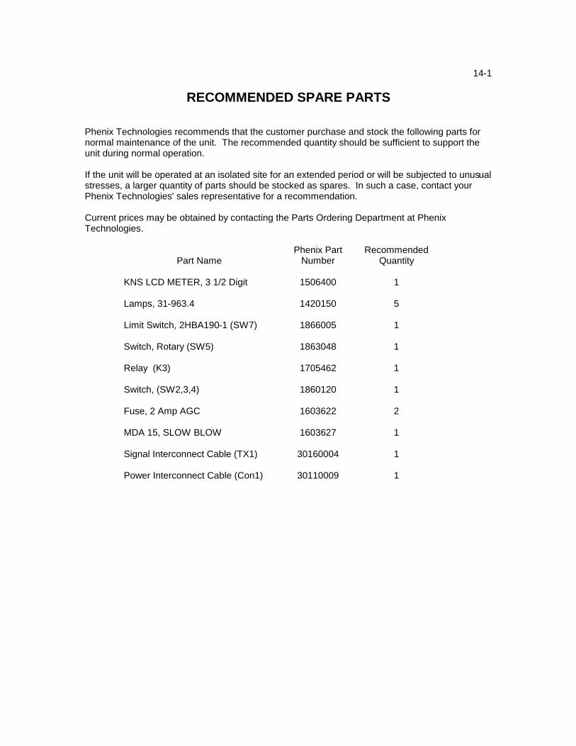
Phenix Technologies recommends that the customer purchase and stock the following parts for normal maintenance of the unit. The recommended quantity should be sufficient to support the unit during normal operation. If the unit will be operated at an isolated site for an extended period or will be subjected to unusual stresses, a larger quantity of parts should be stocked as spares. In such a case, contact your Phenix Technologies' sales representative for a recommendation. Current prices may be obtained by contacting the Parts Ordering Department at Phenix Technologies.
Part Name Phenix Part
Number Recommended
Quantity KNS LCD METER, 3 1/2 Digit 1506400 1 Lamps, 31-963.4 1420150 5 Limit Switch, 2HBA190-1 (SW7) 1866005 1 Switch, Rotary (SW5) 1863048 1 Relay (K3) 1705462 1 Switch, (SW2,3,4) 1860120 1 Fuse, 2 Amp AGC 1603622 2 MDA 15, SLOW BLOW 1603627 1 Signal Interconnect Cable (TX1) 30160004 1 Power Interconnect Cable (Con1) 30110009 1

15-1 WARRANTY
Phenix Technologies, Inc. warrants to the original purchaser of any new merchandise that the merchandise is free from defects in material and workmanship under normal use and service for a period of 18 months from the date of shipment. The obligation of Phenix Technologies, Inc. under this warranty is limited, in its exclusive option, to repair, replace, or issue credit for parts or materials which prove to be defective, and is subject to purchaser's compliance with the Phenix Technologies, Inc. warranty claim procedure as set forth below. The happening of any one or more of the following events will serve to void this warranty and defect or damage resulting therefrom is specifically excluded from warranty coverage: A. Defects due to accident, negligence, alteration, modification, faulty installation by purchaser
or purchaser's agents or employees, abuse, or misuse. B. Attempted or actual dismantling, disassembling, service or repair by any person, firm, or
corporation not specifically authorized in writing by Phenix Technologies, Inc. C. Defects caused by or due to handling by carrier, or incurred during shipment, transshipment,
or other move. This warranty covers only those parts and/or materials deemed by Phenix Technologies, Inc. to be defective within the meaning of this warranty. The liability of Phenix Technologies, Inc. shall be limited to the repair, replacement, or issuance of credit for parts deemed defective within the meaning of this warranty. Costs incurred by purchaser for labor or other expenses incidental to the inspection, repair, replacement, or issuance of credit for such parts and/or material shall be the sole responsibility of purchaser. This warranty shall not apply to any accessories, parts, or materials not manufactured or supplied by Phenix Technologies, Inc. and if, in the sole discretion of Phenix Technologies, Inc., purchaser's claim relates to any materials or workmanship manufactured or performed by the supplier of a component part, or of the manufacturer of a device of which the defective part is a component, Phenix Technologies, Inc. reserves the right to disclaim liability under this warranty and to direct that the purchaser deal directly with such supplier or manufacturer. Phenix Technologies, Inc. agrees to assist the purchaser in processing or settling any such claims without prejudicing its position as to liability. Warranty Claim Procedure Compliance with the following warranty claim procedure is a condition precedent to the obligation of Phenix Technologies, Inc. under this warranty. A. Purchaser must notify Phenix Technologies, Inc. in writing by certified or registered mail, of
the defect claimed within 18 months after date of original shipment. Said notice shall describe in detail the defect, the defective parts and/or part, and the alleged cause of defect.
B. At the exclusive option of Phenix Technologies, Inc., purchaser shall dismantle or dis-
assemble at purchaser's cost and expense and shall ship the defective part or material prepaid to and from Phenix Technologies, Inc., Accident, Maryland 21520, for inspection, or permit an authorized service representative of Phenix Technologies, Inc. to inspect the defective part or material at purchaser's premises. If Phenix Technologies, Inc. shall inspect the part or material at the purchaser's premises, purchaser shall provide facilities for, and at purchaser's cost and expense, dismantle, disassemble, or otherwise make accessible the subject part of material whether or not same is a component of or installed in a device other

15-2 WARRANTY
than that manufactured or supplied by Phenix Technologies, Inc. If disclosure shows that the defect is not one for which Phenix Technologies, Inc. is liable, the purchaser agrees to reimburse Phenix Technologies, Inc. for all expense incurred.
C. Upon receipt of the defective part or material, or after access to same, Phenix Technologies,
Inc. shall inspect the part or material to determine the validity of purchaser's claim. The validity of any warranty claim, purchaser's compliance with Phenix Technologies, Inc. warranty claim procedure, the obligation to either repair, replace, or issue credit, or direct the purchaser to deal directly with a manufacturer or supplier are to be determined solely and exclusively by Phenix Technologies, Inc. and any determination so made shall be final and binding. This warranty is expressly in lieu of all other warranties expressed or implied on the part of Phenix Technologies, Inc., including the warranties or merchantability and fitness for use, and consequential damages arising from any breach thereof and Phenix Technologies, Inc. neither assumes nor authorizes any other person, firm, or corporation to assume any liability or obligation in connection with this sale on its behalf and purchaser acknowledges that no representations except those made herein have been made to purchaser.

16-1 RETURNED MATERIAL
If for any reason it should become necessary to return this equipment to the factory, the Service Department of Phenix Technologies, Inc. must be given the following information:
Name Plate Information
Model Number Serial Number
Reason for Return Cause of Defect
If Phenix Technologies, Inc. deems return of the part appropriate, it will then issue a "Authorization for Return". If return is not deemed advisable, other inspection arrangements will be made. NOTE: Material received at this plant without the proper authorization shall be held as "Customer's Property" with no service until such time as the proper steps have been taken. Your cooperation is requested in order to ensure prompt service.